11/11/2018. Mechanism and Actuations. Joint Actuating System in general consists of: a power supply, a power amplifier, a servomotor, a transmission.
|
|
|
- Alisha Rice
- 5 years ago
- Views:
Transcription

1 Mechanism and Actuations Joint Actuating System in general consists of: a power supply, a power amplifier, a servomotor, a transmission


 problems: friction,")
2 Transmissions Spur gears: modify direction and/or translate axis of (rotational or translational) motor displacement problems: deformations, backlash 3 Transmissions Lead screws: convert rotational into translational motion (prismatic joints) problems: friction, elasticity, backlash 4 2

 5 Harmonic drive : compact,")

3 Transmissions Timing belts and chains: dislocate the motor w.r.t. the joint axis problems: compliance (belts) or vibrations induced by larger mass at high speed (chains) 5 Harmonic drive : compact, in-line, power efficient, with high reduction ratio (up to :1) problems: elasticity Cross-section of a harmonic drive A: circular spline (fixed) B: flex spline (attached to output shaft, not shown) C: wave generator (attached to input shaft, not shown) 6 3
4 Servomotors motors can be classified into three groups Pneumatic motors Hydraulic motors Electric motors the following requirements are necessary for motor used in robots low inertia and high power-to-weight ratio, possibility of overload and delivery of impulse torques, capability to develop high accelerations, wide velocity range (from 1 to 1000 revolutes/min), high positioning accuracy (at least 1/1000 of a circle), low torque ripple so as to guarantee continuous rotation even at low speed. 7 Pneumatic motors are difficult to control accurately, in view of the unavoidable fluid compressibility errors. Therefore, they are not widely employed, if not for the actuation of the typical opening and closing motions of the jaws in a gripper tool. The most employed motors in robotics applications are electric servomotors. Among them, the most popular are permanent-magnet direct-current (DC) servomotors and brushless DC servomotors, in view of their good control flexibility 8 4
 An armature that includes the current-carrying winding A")
 consists of: A rotating coil (rotor)")


5 The permanent-magnet DC servomotor consists of: A stator coil that generates magnetic flux (a permanent magnet) An armature that includes the current-carrying winding A commutator that provides an electric connection by means of brushes 9 The brushless DC servomotor (electronically commutated motors ) consists of: A rotating coil (rotor) that generates magnetic flux (permanent magnet) A stationary armature (stator) made by a polyphase winding A static commutator that, on the basis of the signals provided by a position sensor located on the motor shaft, generates the feed sequence of the armature winding phases as a function of the rotor motion. The motor from a 3.5" floppy disk drive 10 5
6 A comparison between the operating principle of a permanent-magnet DC and a brushless DC The role played by the brushes and commutator in a permanent-magnet DC motor is analogous to that played by the position sensor and electronic control module in a brushless DC motor. By means of the rotor position sensor, the winding orthogonal to the magnetic field of the coil is found; then, feeding the winding makes the rotor rotate. The main reason for using a brushless DC motor is to eliminate the problems due to mechanical commutation of the brushes in a permanent-magnet DC motor. The presence of the commutator limits the performance of a permanentmagnet DC motor, because of electric loss due to voltage drops at the commutator, and mechanical loss due to friction and arcing. 11 the elimination of the commutator allows an improvement of motor performance in terms of higher speeds and less material wear The presence of a winding on the stator instead of the rotor facilitates heat disposal. Therefore, the size of a brushless DC motor is smaller than that of a permanent-magnet DC motor of the same power low moment of inertia and an improvement of dynamic performance and reduced noise can also be obtained by using a brushless DC motor 12 6

7 13 Electric Drives From a modelling viewpoint, a permanent-magnet DC motor and a brushless DC motor provided with the commutation module and position sensor can be described by the same differential equations The mechanical balance is described by the equations 14 7
8 15 Transmission Effects The mechanical balances at the motor side and the load side are respectively: 16 8
9 and finally This expression shows how, in the case of a gear with large reduction ratio, the inertia moment and the viscous friction coefficient of the load are reflected at the motor axis with a reduction of a factor 1/kr 2 ; the reaction torque, instead, is reduced by a factor 1/kr. If this torque depends on ϑ in a nonlinear fashion, then the presence of a large reduction ratio tends to linearize the dynamic equation. 17 Example 5.1 The dynamics is which is further reduced to from which it is clear how the contribution of the nonlinear term is reduced by the factor kr. 18 9

10
 burnout problems at static")

11 Electric servomotors present the following advantages/ limitations: widespread availability of power supply, low cost and wide range of products, high power conversion efficiency, greater control flexibility easy maintenance, no pollution of working environment high speeds and low torques, thus requires the use of gear transmissions (causing elasticity and backlash) burnout problems at static situations caused by the effect of gravity on the manipulator; emergency brakes are then required, need for special protection when operating in flammable environments. 21 Stepper motor: brushless DC electric motor that divides a full rotation into a number of equal steps Advantages of Stepper Motor: The rotation angle of the motor is proportional to the input pulse. The motor has full torque at standstill. Precise positioning and repeatability of movement since good stepper motors have an accuracy of 3 5% of a step and this error is non cumulative from one step to the next. Excellent response to starting, stopping and reversing. Very reliable since there are no contact brushes in the motor. Therefore the life of the motor is simply dependent on the life of the bearing. The motors response to digital input pulses provides open-loop control, making the motor simpler and less costly to control. It is possible to achieve very low speed synchronous rotation with a load that is directly coupled to the shaft. A wide range of rotational speeds can be realized as the speed is proportional to the frequency of the input pulses. Basically can be run open loop, no sensor is needed 22 11
12 Hydraulic servomotors, Linear servomotors have a limited range and are constituted by a single piston. Rotary servomotors have unlimited range and are constituted by several pistons 23 Hydraulic servomotors present the following advantages/drawbacks: do not suffer from burnout in static situations self-lubricated and the circulating fluid facilitates heat disposal inherently safe in harmful environments have excellent power-to-weight ratios high torques at low speeds need for a hydraulic power station high cost, narrow range of products, and difficulty of miniaturization low power conversion efficiency need for operational maintenance pollution of working environment due to oil leakage 24 12
13 Electrical Motor: key information & selection attached pdf 25 13
. The losses that arise are divided into frictional losses, attributable to P mech and in Joule power losses P J of the winding (resistance R).")

 Speeds (rpm) instead of angular velocity (rad/s) The detailed result is as follows U mot I mot = 30")
14 maxon DC motor and maxon EC motor Key information maxon motor The motor as an energy converter The electrical motor converts electrical power P el (current I mot and voltage U mot ) into mechanical power P mech (speed n and torque M). The losses that arise are divided into frictional losses, attributable to P mech and in Joule power losses P J of the winding (resistance R). Iron losses do not occur in the coreless maxon DC motors. In maxon EC motors, they are treated formally like an additional friction torque. The power balance can therefore be formulated as: P el = P mech + P J See also: Technology short and to the point, explanation of the motor Units In all formulas, the variables are to be used in the units according to the catalog (cf. physical variables and their units on page 48). The following applies in particular: All torques in mnm All currents in A (even no load currents) Speeds (rpm) instead of angular velocity (rad/s) The detailed result is as follows U mot I mot = n M + R I mot 2 P el = U mot I mot Electromechanical motor constants The geometric arrangement of the magnetic circuit and winding defines in detail how the motor converts the electrical input power (current, voltage) into mechanical output power (speed, torque). Two important characteristic values of this energy conversion are the speed constant k n and the torque constant k M. The speed constant combines the speed n with the voltage induced in the winding U ind (= EMF). U ind is proportional to the speed; the following applies: P mech = M n P J = R I mot 2 n = k n U ind Similarly, the torque constant links the mechanical torque M with the electrical current I mot. Motor constants Speed constant k n and torque constant k M are not independent of one another. The following applies: M = k M I mot The main point of this proportionality is that torque and current are equivalent for the maxon motor. The current axis in the motor diagrams is therefore shown as parallel to the torque axis as well. The speed constant is also called specific speed. Specific voltage, generator or voltage constants are mainly the reciprocal value of the speed constant and describe the voltage induced in the motor per speed. The torque constant is also called specific torque. The reciprocal value is called specific current or current constant. Motor diagrams A diagram can be drawn for every maxon DC and EC motor, from which key motor data can be taken. Although tolerances and temperature influences are not taken into consideration, the values are sufficient for a first estimation in most applications. In the diagram, speed n, current I mot, power output P 2 and efficiency h are applied as a function of torque M at constant voltage U mot. Speed-torque line This curve describes the mechanical behavior of the motor at a constant voltage U mot : Speed decreases linearly with increasing torque. The faster the motor turns, the less torque it can provide. The curve can be described with the help of the two end points, no load speed n 0 and stall torque M H (cf. lines 2 and 7 in the motor data). DC motors can be operated at any voltage. No load speed and stall torque change proportionally to the applied voltage. This is equivalent to a parallel shift of the speed-torque line in the diagram. Between the no load speed and voltage, the following proportionality applies in good approximation n 0 k n U mot where k n is the speed constant (line 13 of the motor data). Independent of the voltage, the speed-torque line is described most practically by the slope or gradient of the curve (line 14 of the motor data). Δn ΔM n 0 = MH Speed n Derivation of the speed-torque line The following occurs if one replaces current I mot with torque M using the torque constant in the detailed power balance: 2 M M U mot = n M + R k M k M Transformed and taking account of the close relationship of k M and k n, an equation is produced of a straight line between speed n and torque M. n = k n U mot R 2 M k M or with the gradient and the no load speed n 0 Δn n = n 0 ΔM M Torque M 42 Key information November 2015 edition / subject to change
15 The speed-torque gradient is one of the most informative pieces of data and allows direct comparison between different motors. The smaller the speed-torque gradient, the less sensitive the speed reacts to torque (load) changes and the stronger the motor. With the maxon motor, the speedtorque gradient within the winding series of a motor type (i.e. on one catalog page) remains practically constant. Speed n n 0 U = U N maxon motor Current gradient The equivalence of current to torque is shown by an axis parallel to the torque: more current flowing through the motor produces more torque. The current scale is determined by the two points no load current I 0 and starting current I A (lines 3 and 8 of motor data). The no load current is equivalent to the friction torque M R, that describes the internal friction in the bearings and commutation system. Torque M M R = k M I 0 I A Current I In the maxon EC motor, there are strong, speed dependent iron losses in the stator iron stack instead of friction losses in the commutation system. The motors develop the highest torque when starting. It is many times greater than the normal operating torque, so the current uptake is the greatest as well. The following applies for the stall torque M H and starting current I A M H = k M I A Efficiency curve The efficiency h describes the relationship of mechanical power delivered to electrical power consumed. η = n (M M R ) U mot I mot One can see that at constant applied voltage U and due to the proportionality of torque and current, the efficiency increases with increasing speed (decreasing torque). At low torques, friction losses become increasingly significant and efficiency rapidly approaches zero. Maximum efficiency (line 9 of motor data) is calculated using the starting current and no load current and is dependent on voltage. n 0 η max = 1 I 0 I A 2 M H Torque M Maximum efficiency and maximum output power do not occur at the same torque. Rated operating point The rated operating point is an ideal operating point for the motor and derives from operation at nominal voltage U N (line 1 of motor data) and nominal current I N (line 6). The nominal torque M N produced (line 5) in this operating point follows from the equivalence of torque and current. Speed n M N k M (I N I 0 ) Nominal speed n N (line 4) is reached in line with the speed gradient. The choice of nominal voltage follows from considerations of where the maximum no load speed should be. The nominal current derives from the motor s thermally maximum permissible continuous current. n N M N I N Torque M Current I November 2015 edition / subject to change Key information 43
16 Motor diagrams, operating ranges maxon motor The catalog contains a diagram of every maxon DC and EC motor type that shows the operating ranges of the different winding types using a typical motor. Permanent operating range The two criteria maximum continuous torque and maximum permissible speed limit the continuous operating range. Operating points within this range are not critical thermally and do not generally cause increased wear of the commutation system. Short-term operating range The motor may only be loaded with the maximum continuous current for thermal reasons. However, temporary higher currents (torques) are allowed. As long as the winding temperature is below the critical value, the winding will not be damaged. Phases with increased currents are time limited. A measure of how long the temporary overload can last is provided by the thermal time constant of the winding (line 19 of the motor data). The magnitude of the times with overload ranges from several seconds for the smallest motors (6 mm to 13 mm diameter) up to roughly one minute for the largest (60 mm to 90 mm diameter). The calculation of the exact overload time is heavily dependent on the motor current and the rotor s starting temperature Operating range diagram Maximum continuous current, maximum continuous torque The Jule power losses heat up the winding. The heat produced must be able to dissipate and the maximum rotor temperature (line 22 of the motor data) should not be exceeded. This results in a maximum continuous current, at which the maximum winding temperature is attained under standard conditions (25 C ambient temperature, no heat dissipation via the flange, free air circulation). Higher motor currents cause excessive winding temperatures. The nominal current is selected so that it corresponds to this maximum permissible constant current. It depends heavily on the winding. These thin wire windings have lower nominal current levels than thick ones. With very low resistive windings, the brush system s capacity can further limit the permissible constant current. With graphite brush motors, friction losses increase sharply at higher speeds. With EC motors, eddy current losses increase in the return as speed increases and produce additional heat. The maximum permissible continuous current decreases at faster speeds accordingly. The nominal torque allocated to the nominal current is almost constant within a motor type s winding range and represents a characteristic size of the motor type. The maximum permissible speed for DC motors is primarily limited by the commutation system. The commutator and brushes wear more rapidly at very high speeds. The reasons are: Increased mechanical wear because of the large traveled path of the commutator Increased electro-erosion because of brush vibration and spark formation. I ON / I N T Time A further reason for limiting the speed is the rotor s residual mechanical imbalance which shortens the service life of the bearings. Higher speeds than the limit speed n max (line 23) are possible, however, they are paid for by a reduced service life expectancy. The maximum permissible speed for the EC motor is calculated based on service life considerations of the ball bearings (at least hours) at the maximum residual imbalance and bearing load. Maximum winding temperature The motor current causes the winding to heat up due to the winding s resistance. To prevent the motor from overheating, this heat must dissipate to the environment via the stator. The coreless winding is the thermally critical point. The maximum rotor temperature must not be exceeded, even temporarily. With graphite brush motors and EC motors which tend to have higher current loads, the maximum rotor temperature is 125 C (in individual cases up to 155 C). Motors with precious metal commutators only allow lower current loads, so that the rotor temperatures must not exceed 85 C. Favourable mounting conditions, such as good air circulation or cooling plates, can significantly lower temperatures t ON% ON Motor in operation OFF Motor stationary I ON Max. peak current I N Max. permissible continuous current (line 6) t ON ON time [s], should not exeed t w (line 19) T Cycle time t ON + t OFF [s] t ON% Duty cycle as percentage of cycle time. The motor may be overloaded by the relationship I ON / I N at X % of the total cycle time. I on = I N T t ON 44 Key information November 2015 edition / subject to change
17 maxon flat motor Multipole EC motors, such as maxon flat motors, require a greater number of commutation steps for a motor revolution (6 x number of pole pairs). Due to the wound stator teeth they have a higher terminal inductance than motors with an ironless winding. As a result at higher speed, the current cannot develop fully during the correspondingly short commutation intervals. Therefore, the apparent torque produced is lower. Current is also fed back into the controller s power stage. As a result, motor behaviour deviates from the ideal linear speed-torque gradient. The apparent speed-torque gradient depends on voltage and speed: The gradient is steeper at higher speeds. Mostly, flat motors are operated in the continuous operation range where the achievable speed-torque gradient at nominal voltage can be approximated by a straight line between no load speed and nominal operating point. The achievable speed-torque gradient is approximately. Speed n U>U N U=U N U<U N Nominal operating point U N ideal Torque M maxon motor Δn ΔM n 0 n N M N Acceleration In accordance with the electrical boundary conditions (power supply, control, battery), a distinction is principally made between two different starting processes: Start at constant voltage (without current limitation) Start at constant current (with current limitation) Start under constant current A current limit always means that the motor can only deliver a limited torque. In the speed-torque diagram, the speed increases on a vertical line with a constant torque. Acceleration is also constant, thus simplifying the calculation. Start at constant current is usually found in applications with servo amplifiers, where acceleration torques are limited by the amplifier s peak current. Start with constant terminal voltage Here, the speed increases from the stall torque along the speedtorque line. The greatest torque and thus the greatest acceleration is effective at the start. The faster the motor turns, the lower the acceleration. The speed increases more slowly. This exponentially flattening increase is described by the mechanical time constant t m (line 15 of the motor data). After this time, the rotor at the free shaft end has attained 63% of the no load speed. After roughly three mechanical time constants, the rotor has almost reached the no load speed. n U = constant n n l = constant n M Time M Time Mechanical time constant t m (in ms) of the unloaded motor: J R R τ m = 100 k M 2 Angular acceleration a (in rad / s 2 ) at constant current I or constant torque M with an additional load of inertia J L : k M I mot M α = 10 4 = 10 J R + J 4 L J R + J L Run-up time Dt (in ms) at a speed change Dn with an additional load inertia J L : J R + J L Δt = Δn 300 k M I mot (all variables in units according to the catalog) Mechanical time constants t m (in ms) with an additional load inertia J L : J R R J τ m ' = L 2 k M J R Maximum angular acceleration a max (in rad / s 2 ) of the unloaded motor: M H α max = 10 4 J R Maximum angular acceleration a max (in rad / s 2 ) with an additional load inertia J L : M H α max = 10 4 J R + J L Run-up time (in ms) at constant voltage up to the operating point (M L, n L ): Δt = τ m ' In M L + M R 1 n M 0 H 1 M L + M R M H n 0 n L November 2015 edition / subject to change Key information 45
18 Tolerances maxon motor Tolerances must be considered in critical ranges. The possible deviations of the mechanical dimensions can be found in the overview drawings. The motor data are average values: the adjacent diagram shows the effect of tolerances on the curve characteristics. They are mainly caused by differences in the magnetic field strength and in wire resistance, and not so much by mechanical influences. The changes are heavily exaggerated in the diagram and are simplified to improve understanding. It is clear, however, that in the motor s actual operating range, the tolerance range is more limited than at start or at no load. Our computer sheets contain all detailed specifications. Tolerance field presentation for maxon motors Tolerance for starting current Calibrating The tolerances can be limited by controlled de-magnetization of the motors. Motor data can be accurately specified down to 1 to 3%. However, the motor characteristic values lie in the lower portion of the standard tolerance range. Reduced tolerance field for k M Normal distribution Thermal behavior The Joule power losses P J in the winding determine heating of the motor. This heat energy must be dissipated via the surfaces of the winding and motor. The increase DT W of the winding temperature T W with regard to the ambient temperature arises from heat losses P J and thermal resistances R th1 and R th2. T W T U = DT W = (R th1 + R th2 ) P J Here, thermal resistance R th1 relates to the heat transfer between the winding and the stator (magnetic return and magnet), whereas R th2 describes the heat transfer from the housing to the environment. Mounting the motor on a heat dissipating chassis noticeably lowers thermal resistance R th2. The values specified in the data sheets for thermal resistances and the maximum continuous current were determined in a series of tests, in which the motor was end-mounted onto a vertical plastic plate. The modified thermal resistance R th2 that occurs in a particular application must be determined using original installation and ambient conditions. Thermal resistance R th2 on motors with metal flanges decreases by up to 80% if the motor is coupled to a good heat-conducting (e.g. metallic) retainer. Influence of temperature An increased motor temperature affects winding resistance and magnetic characteristic values. Winding resistance increases linearly according to the thermal resistance coefficient for copper (α Cu = ): R T = R 25 (1 + α Cu (T 25 C)) Example: a winding temperature of 75 C causes the winding resist- ance to increase by nearly 20%. The magnet becomes weaker at higher temperatures. The reduction is 1 to 10% at 75 C depending on the magnet material. The most important consequence of increased motor temperature is that the speed curve becomes steeper which reduces the stall torque. The changed stall torque can be calculated in first approximation from the voltage and increased winding resistance: The heating runs at different rates for the winding and stator due to the different masses. After switching on the current, the winding heats up first (with time constants from several seconds to half a minute). The stator reacts much slower, with time constants ranging from 1 to 30 minutes depending on motor size. A thermal balance is gradually established. The temperature difference of the winding compared to the ambient temperature can be determined with the value of the current I (or in intermittent operation with the effective value of the current I = I RMS ). M H = k M I A = k M U mot R T 2 (R th1 + R th2 ) R I mot ΔT W = 2 1 α Cu (R th1 + R th2 ) R I mot Here, electrical resistance R must be applied at the actual ambient temperature. 46 Key information November 2015 edition / subject to change
19 Motor selection The drive requirements must be defined before proceeding to motor selection. How fast and at which torques does the load move? How long do the individual load phases last? What accelerations take place? How great are the mass inertias? Often the drive is indirect, this means that there is a mechanical transformation of the motor output power using belts, gears, screws and the like. The drive parameters, therefore, are to be calculated to the motor shaft. Additional steps for gear selection are listed below. Furthermore, the power supply requirements need to be checked. Which maximum voltage is available at the motor terminals? Which limitations apply with regard to current? The current and voltage of motors supplied with batteries or solar cells are very limited. In the case of control of the unit via a servo amplifier, the amplifier s maximum current is often an important limit. Selection of motor types The possible motor types are selected using the required torque. On the one hand, the peak torque, M max, is to be taken into consideration and on the other, the effective torque M RMS. Continuous operation is characterized by a single operating or load point (M L, n L ). The motor types in question must have a nominal torque (= max. continuous torque) M N that is greater than load torque M L. M N > M L In operating cycles, such as start/stop operation, the motor s nominal torque must be greater than the effective load torque (RMS). This prevents the motor from overheating. M N > M RMS Advices for evaluating the requirements: Often the load points (especially the torque) are not known or are difficult to determine. In such cases you can operate your device with a measuring motor roughly estimated according to size and power. Vary the voltage until the desired operating points and motion sequences have been achieved. Measure the voltage and current flow. Using these specifications and the part number of the measuring motor, our engineers can often specify the suitable motor for your application. Additional optimization criteria are, for example: Mass to be accelerated (type, mass inertia) Type of operation (continuous, intermittent, reversing) Ambient conditions (temperature, humidity, medium) Power supply, battery When selecting the motor type, other constraints also play a major role: What maximum length should the drive unit have, including gear and encoder? What diameter? What service life is expected from the motor and which commutation system should be used? Precious metal commutation for continuous operation at low currents (rule of thumb for longest service life: up to approx. 50% of I N ). Graphite commutation for high continuous currents (rule of thumb: 50% to approx. 75% of I N ) and frequent current peaks (start/stop operation, reversing operation). Electronic commutation for highest speeds and longest service life. How great are the forces on the shaft, do ball bearings have to be used or are less expensive sintered bearings sufficient? maxon motor The stall torque of the selected motor should usually exceed the emerging load peak torque. M H > M max Selection of the winding: electric requirement In selecting the winding, it must be ensured that the voltage applied directly to the motor is sufficient for attaining the required speed in all operating points. Uncontrolled operation In applications with only one operating point, this is often achieved with a fixed voltage U. A winding is sought with a speed-torque line that passes through the operating point at the specified voltage. The calculation uses the fact that all motors of a type feature practically the same speed-torque gradient. A target no load speed n 0,theor is calculated from operating point (n L, M L ). Δn n 0, theor = n L + M ΔM L n Speed-torque line high enough for the required load speed U = constant This target no load speed must be achieved with the existing voltage U, which defines the target speed constant. k n, theor = n 0, theor U mot Speed-torque line too low for the required load speed M Those windings whose kn is as close to k n, theor as possible, will approximate the operating point the best at the specified voltage. A somewhat larger speed constant results in a somewhat higher speed, a smaller speed constant results in a lower one. The variation of the voltage adjusts the speed to the required value, a principle that servo amplifiers also use. The motor current I mot is calculated using the torque constant k M of the selected winding and the load torque M L. M I L mot = k M November 2015 edition / subject to change Key information 47
20 maxon motor Regulated servo drives In operating cycles, all operating points must lie beneath the curve at a maximum voltage U max. Mathematically, this means that the following must apply for all operating points (n L, M L ): k Δn n U max = n 0 > n L + M ΔM L When using servo amplifiers, a voltage drop occurs at the power stage, so that the effective voltage applied to the motor is lower. This must be taken into consideration when determining the maximum supply voltage U max. It is recommended that a regulating reserve of some 20% be included, so that regulation is even ensured with an unfavorable tolerance situation of motor, load, amplifier and supply voltage. Finally, the average current load and peak current are calculated ensuring that the servo amplifier used can deliver these currents. In some cases, a higher resistance winding must be selected, so that the currents are lower. However, the required voltage is then increased. n Speed-torque line too low for all operating points braking Speed-torque line high enough for all operating points accelerating M Example for motor/gear selection A drive should move cyclically according to the following speed diagram. n The inertia of the load to be accelerated J L is gcm 2. The constant coefficient is approximately 300 mnm. The 4-quadrant operation allows controlled and dynamic motor operation and brake operation in two directions of rotation (all 4 quadrants). The power supply unit delivers max. 3 A and 24 V. Calculation of load data The torque required for acceleration and braking are calculated as follows (motor and gearhead inertia omitted): π Δn M α = J L = Δt π = Nm = 176 mnm Together with the friction torque, the following torques result for the different phases of motion. Acceleration phase (duration 0.5 s) 476 mnm Constant speed (duration 2 s) 300 mnm Braking (friction brakes with 300 mnm) (duration 0.5 s) 124 mnm Standstill (duration 0.7 s) 0 mnm Peak torque occurs during acceleration. The RMS determined torque of the entire operating cycle is M RMS = = n = 60 rpm t 1 M t 2 M t 3 M t 4 M 2 4 t tot mnm 3.7 The maximum speed (60 rpm) occurs at the end of the acceleration phase at maximum torque (463 mnm). Thus, the peak mechanical power is: π π P max = M max n 30 max = W 30 Time (s) Physical variables and their units SI Catalog i Gear reduction* I mot Motor current A A, ma I A Stall current* A A, ma I 0 No load current* A ma I RMS RMS determined current A A, ma I N Nominal current* A A, ma J R Moment of inertia of the rotor* kgm 2 gcm 2 J L Moment of inertia of the load kgm 2 gcm 2 k M Torque constant* Nm/A mnm/a k n Speed constant* rpm/v M (Motor) torque Nm mnm M L Load torque Nm mnm M H Stall torque* Nm mnm M mot Motor torque Nm mnm M R Moment of friction Nm mnm M RMS RMS determined torque Nm mnm M N Nominal torque Nm mnm M N,G Max. torque of gear* Nm Nm n Speed rpm n L Operating speed of the load rpm n max Limit speed of motor* rpm n max,g Limit speed of gear* rpm n mot Motor speed rpm n 0 No load speed* rpm P el Electrical power W W P J Joule power loss W W P mech Mechanical power W W R Terminal resistance W W R 25 Resistance at 25 C* W W R T Resistance at temperature T W W R th1 Heat resistance winding housing* K/W R th2 Heat resistance housing/air* K/W t Time s s T Temperature K C T max Max. winding temperature* K C T U Ambient temperature K C T W Winding temperature K C U mot Motor voltage V V U ind Induced voltage (EMF) V V U max Max. supplied voltage V V U N Nominal voltage* V V a Cu Resistance coefficient of Cu = a max Max. angle acceleration rad/s 2 Dn/DM Curve gradient* rpm/mnm DT W Temperature difference winding/ambient K K Dt Run up time s ms h (Motor) efficiency % h G (Gear) efficiency* % h max Max. efficiency* % t m Mechanical time constant* s ms t S Therm. time constant of the motor* s s t W Therm. time constant of the winding* s s (*Specified in the motor or gear data) 48 Key information November 2015 edition / subject to change
21 Gear selection A gear is required with a maximum continuous torque of at least 0.28 Nm and an intermittent torque of at least 0.47 Nm. This requirement is fulfilled, for example, by a planetary gear with 22 mm diameter (metal version GP 22 A). The recommended input speed of 6000 rpm allows a maximum reduction of: i max = n max, G = 6000 = 100:1 n B 60 We select the three-stage gear with the next smallst reduction of 84 : 1 (stock program). Efficiency is max. 59%. Motor type selection Speed and torque are calculated to the motor shaft n mot = i n L = = 5040 rpm n[rpm] 9.3 mnm, 5040 rpm maxon motor M RMS M mot, RMS = i ɳ = mnm M max M mot, max = i ɳ = mnm The possible motors, which match the selected gears in accordance with the maxon modular system, are summarized in the table opposite. The table contains only DC motors with graphite commutation, which are better suited for start-stop operation, as well as brushless EC motors. Selection falls on an A-max 22, 6 W, which demonstrates a sufficiently high continuous torque. The motor should have a torque reserve so that it can even function with a somewhat unfavorable gear efficiency. The additional torque requirement during acceleration can easily be delivered by the motor. The temporary peak torque is not even twice as high as the continuous torque of the motor. Selection of the winding The motor type A-max 22, 6 W has an average speed-torque gradient of some 450 rpm/mnm. However, it should be noted that the two lowest resistance windings have a somewhat steeper gradient. The desired no load speed is calculated as follows: Motor M N Suitability A-max 22, 6 W 6.9 mnm good A-max 19, 2.5 W 3.8 mnm too weak RE-max 21, 6 W 6.8 mnm good EC 16, 30 W 8.5 mnm good EC 16, 60 W 17 mnm too strong EC 20 flat, 3 W 3-4 mnm too weak EC 20 flat, 5 W 7.5 mnm good EC 20 flat, 5 W, ie. 7.5 mnm good, possible alternative with integrated speed controller, no ESCON control necessary Δn n 0, theor = n mot + ΔM M max = = 9360 min 1 The extreme operating point should of course be used in the calculation (max. speed and max. torque), since the speed-torque line of the winding must run above all operating points in the speed / torque diagram. This target no load speed must be achieved with the maximum voltage U = 24 V supplied by the control (ESCON 36/2), which defines the minimum target speed constant k n, theor of the motor. k n, theor = n 0, theor 9360 = = 390 U mot 24 min 1 V According to the calculations, the selection of the motor is , which with its speed constant of 558 rpm/v has a speed control reserve of over 20%. This means that unfavorable tolerances are not a problem. The higher speed constant of the winding compared to the calculated value means that the motor runs faster at 24 V than required, which can be compensated with the controller. This motor also has a second shaft end for mounting an encoder. The torque constant of this winding is 17.1 mnm/a. Therefore the maximum torque corresponds to a peak current of: Imax = M max I k 0 = = 0.6 A M 17.1 This current is smaller than the maximum current (4 A) of the controller and the power supply unit (3 A). Thus, a gear motor has been found that fulfils the requirements (torque and speed) and can be operated by the controller provided. November 2015 edition / subject to change Key information 49
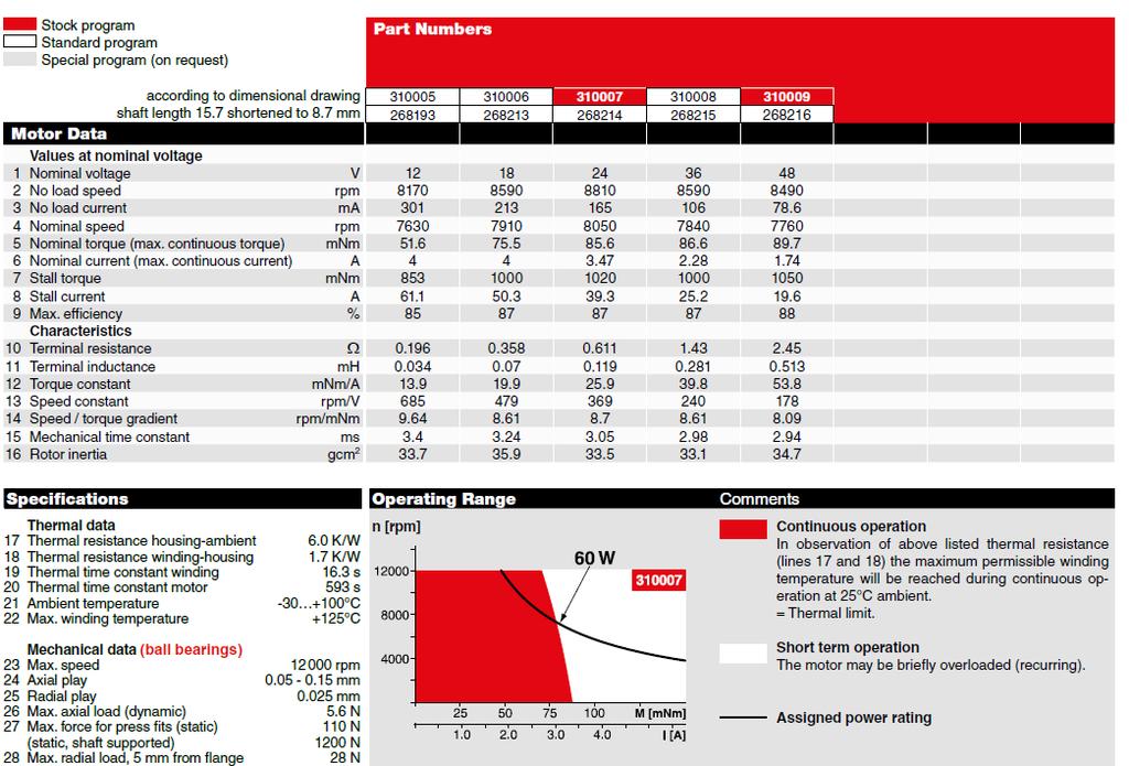
22 A-max mm, Graphite Brushes, 6 Watt maxon A-max M 1:1 Stock program Standard program Special program (on request) Part Numbers Motor Data Values at nominal voltage 1 Nominal voltage V 2 No load speed rpm 3 No load current ma 4 Nominal speed rpm 5 Nominal torque (max. continuous torque) mnm 6 Nominal current (max. continuous current) A 7 Stall torque mnm 8 Stall current A 9 Max. efficiency % Characteristics 10 Terminal resistance W 11 Terminal inductance mh 12 Torque constant mnm/a 13 Speed constant rpm/v 14 Speed / torque gradient rpm/mnm 15 Mechanical time constant ms 16 Rotor inertia gcm 2 with terminals with cables Specifications Operating Range Comments Thermal data 17 Thermal resistance housing-ambient 18 Thermal resistance winding-housing 19 Thermal time constant winding 20 Thermal time constant motor 21 Ambient temperature 22 Max. winding temperature 20 K/W 6.0 K/W 10.2 s 313 s C +125 C Mechanical data (sleeve bearings) 23 Max. speed 9800 rpm 24 Axial play mm 25 Radial play mm 26 Max. axial load (dynamic) 1 N 27 Max. force for press fits (static) 80 N (static, shaft supported) 440 N 28 Max. radial load, 5 mm from flange 2.8 N Mechanical data (ball bearings) 23 Max. speed 9800 rpm 24 Axial play mm 25 Radial play mm 26 Max. axial load (dynamic) 3.3 N 27 Max. force for press fits (static) 45 N (static, shaft supported) 240 N 28 Max. radial load, 5 mm from flange 12.3 N Other specifications 29 Number of pole pairs 30 Number of commutator segments 31 Weight of motor Values listed in the table are nominal. Explanation of the figures on page 107. Option Ball bearings in place of sleeve bearings g n [rpm] Continuous operation In observation of above listed thermal resistance (lines 17 and 18) the maximum permissible winding temperature will be reached during continuous operation at 25 C ambient. = Thermal limit. Short term operation The motor may be briefly overloaded (recurring). Assigned power rating maxon Modular System Overview on page Planetary Gearhead 22 mm Nm Page 291/292 Planetary Gearhead 22 mm Nm Page 293/295 Spur Gearhead 24 mm 0.1 Nm Page 300 Spindle Drive 22 mm Page 332/333 Recommended Electronics: Notes Page 22 ESCON Module 24/2 378 ESCON 36/2 DC 378 ESCON Module 50/5 379 ESCON 50/5 380 EPOS2 24/2 386 EPOS2 Module 36/2 386 EPOS2 50/5 387 EPOS3 70/10 EtherCAT 393 MAXPOS 50/5 396 Encoder MR 32 CPT, 2 / 3 channels Page 351 Encoder MR 128 / 256 / 512 CPT, 2 / 3 channels Page 353 Encoder Enc 22 mm 100 CPT, 2 channels Page 361 Encoder MEnc 13 mm 16 CPT, 2 channels Page maxon DC motor November 2015 edition / subject to change
23 Planetary Gearhead GP 22 A 22 mm, Nm M 1:2 Technical Data Planetary Gearhead straight teeth Output shaft stainless steel, hardened Bearing at output ball bearing Option sleeve bearing Radial play, 10 mm from flange max. 0.2 mm Axial play max. 0.2 mm Max. axial load (dynamic) 100 N Max. force for press fits 100 N Direction of rotation, drive to output = Max. continuous input speed 6000 rpm Recommended temperature range C Number of stages Max. radial load, 10 mm from flange 30 N 50 N 55 N 55 N 55 N maxon gear Stock program Standard program Special program (on request) Gearhead Data 1 Reduction 2 Absolute reduction 3 Max. motor shaft diameter mm Part Numbers 1 Reduction 2 Absolute reduction 3 Max. motor shaft diameter mm Part Numbers 1 Reduction 2 Absolute reduction 3 Max. motor shaft diameter mm Part Numbers 1 Reduction 2 Absolute reduction 3 Max. motor shaft diameter mm Part Numbers 1 Reduction 2 Absolute reduction 3 Max. motor shaft diameter mm Part Numbers 1 Reduction 2 Absolute reduction 3 Max. motor shaft diameter mm 4 Number of stages 5 Max. continuous torque Nm 6 Max. intermittent torque at gear output Nm 7 Max. efficiency % 8 Weight g 9 Average backlash no load 10 Mass inertia gcm 2 11 Gearhead length L1* mm *for EC 32fl. L1 is mm Part Numbers : 1 14 : 1 53 : : : : : : : : : :1 16 : 1 62 : : : : : : : : : : 1 19 : 1 72 : : : : : : : : : : 1 76 : : : : : : : : 1 84 : : : : : : : 1 89 : : : : : : maxon Modular System + Motor Page + Sensor/Brake Page Overall length [mm] = Motor length + gearhead length + (sensor/brake) + assembly parts A-max / A-max 19, 1.5 W 154 MR 351/ A-max 19, 1.5 W 154 Enc A-max 19, 1.5 W 154 MEnc A-max 19, 2.5 W 155/ A-max 19, 2.5 W 156 MR 351/ A-max 19, 2.5 W 156 Enc A-max 19, 2.5 W 156 MEnc A-max A-max /160 MR 351/ A-max /160 Enc A-max /160 MEnc RE-max / RE-max 21, 3.5 W 180 MR 352/ RE-max 21, 6 W 181/ RE-max 21, 6 W 182 MR 352/ EC 16, 30 W EC 16, 30 W 200 MR EC 16, 60 W EC 16, 60 W 202 MR EC 20 flat, 3 W, A EC 20 flat, 3 W, B EC 20 flat, 5 W EC 20 flat, IE, IP EC 20 flat, IE, IP EC 20 flat, IE, IP EC 20 flat, IE, IP EC 32 flat, 6 W October 2015 edition / subject to change maxon gear 293
HPCMAX HPCMAX203892
 DC Motors 13mm Dia. Motor ø1.5mm Motor Shaft 1.2 Watt - Precious Metal Bushes X Motors 1.2 W ø13 mm Motor Data HPCMAX203889 HPCMAX203892 Values at nominal voltage 1 Nominal voltage V 6.0 12.0 2 No load
Robot components: Actuators
 Robotics 1 Robot components: Actuators Prof. Alessandro De Luca Robotics 1 1 Robot as a system program of tasks commands Robot actions working environment mechanical units supervision units sensor units
Sensorless Brushless DC-Servomotors
 Sensorless Brushless DC-Servomotors FAULHABER Brushless DC-Servomotors are built for extreme operating conditions. They are precise, have exceptionally long lifetimes and are highly reliable. Outstanding
Robot components: Actuators
 Robotics 1 Robot components: Actuators Prof. Alessandro De Luca Robotics 1 1 Robot as a system program of tasks commands Robot actions working environment mechanical units supervision units sensor units
Motor Type Selection. maxon s EC 4-pole brushless motors
 Motor Type Selection Parameters that define a motor type are the mechanical output power, the shaft bearing system, the commutation system used, and the possible combinations with gearheads and sensors.
General Terms and Conditions:
 Your configuration Part number*: B72DB9E3BD8D Consists of: Motor - DCX22S GB KL 12V Planetary gearhead - GPX22 C 21:1 maxon motor worldwide http://www.maxonmotor.com/maxon/view/content/contact_page E-Mail:
4,5 / 27 2,0 / steel, black coated. clockwise, viewed from the front face. ø15,9 ø17-0,052 ø6-0,05. ø3,5 8,1 ±0,3 2, T
 DC-Micromotors Precious Metal Commutation mnm For combination with (overview on page 4-5) Gearheads: 5, 6, 6/7 Encoders: IE 6... 5 Series 3 4 77... SR Nominal voltage Terminal resistance Output power Efficiency
After an order is placed at the e-shop, the product is manufactured in Switzerland and shipped from the factory within 11 days.
 Your configuration Part number*: B72DB9F4DC02 Consists of: Motor - DCX22S GB KL 24V Planetary gearhead - GPX22 C 326:1 maxon motor worldwide http://www.maxonmotor.com/maxon/view/content/contact_page E-Mail:
maxon EC-4pole maxon -4pole
 Sensor Spindle drive maxon -4pole Gearhead EC Motor (BLDC Motor) DC Motor X Drives (configurable) Motor control This 4-pole power motor is one of the best in its class and demonstrates excellent performance
Application Notes. Calculating Mechanical Power Requirements. P rot = T x W
 Application Notes Motor Calculations Calculating Mechanical Power Requirements Torque - Speed Curves Numerical Calculation Sample Calculation Thermal Calculations Motor Data Sheet Analysis Search Site
Power in new dimensions
 NEW FAULHABER BXT Power in new dimensions WE CREATE MOTION EN Angaben zu Lebensdauer sowie weitere technische Erläuterungen 1 FAULHABER BXT Today, you don't find visionary designs in Hollywood, but rather
CHAPTER 3 DESIGN OF THE LIMITED ANGLE BRUSHLESS TORQUE MOTOR
 33 CHAPTER 3 DESIGN OF THE LIMITED ANGLE BRUSHLESS TORQUE MOTOR 3.1 INTRODUCTION This chapter presents the design of frameless Limited Angle Brushless Torque motor. The armature is wound with toroidal
maxon X drives Configure online. dcx.maxonmotor.com DYNAMIC HIGH PERFORMANCE LOW NOISE FAST PROCESSING
 maxon drives Configure online. DYAMIC HIGH PERFORMACE LO OISE X Drives (configurable) FAST PROCESSIG Spindle drive DC Motor Gearhead EC Motor (BLDC Motor) Sensor Motor control Configure, combine and order
Application Information
 Moog Components Group manufactures a comprehensive line of brush-type and brushless motors, as well as brushless controllers. The purpose of this document is to provide a guide for the selection and application
Data Sheet. Size 1 and 2 Stepper Motors. 7.5 stepper motors Size 1 (RS stock no ) Size 2 (RS stock no ) Data Pack B
 Size 2 (RS stock no ) Data Pack B") Data Pack B Issued November 005 1504569 Data Sheet Size 1 and Stepper Motors 7.5 stepper motors Size 1 (S stock no. 33-947) Size (S stock no. 33-953) Two 7.5 stepper motors each with four 1Vdc windings
Data Pack B Issued November 005 1504569 Data Sheet Size 1 and Stepper Motors 7.5 stepper motors Size 1 (S stock no. 33-947) Size (S stock no. 33-953) Two 7.5 stepper motors each with four 1Vdc windings
CHAPTER THREE DC MOTOR OVERVIEW AND MATHEMATICAL MODEL
 CHAPTER THREE DC MOTOR OVERVIEW AND MATHEMATICAL MODEL 3.1 Introduction Almost every mechanical movement that we see around us is accomplished by an electric motor. Electric machines are a means of converting
Page 1. Design meeting 18/03/2008. By Mohamed KOUJILI
 Page 1 Design meeting 18/03/2008 By Mohamed KOUJILI I. INTRODUCTION II. III. IV. CONSTRUCTION AND OPERATING PRINCIPLE 1. Stator 2. Rotor 3. Hall sensor 4. Theory of operation TORQUE/SPEED CHARACTERISTICS
INTRODUCTION Principle
 DC Generators INTRODUCTION A generator is a machine that converts mechanical energy into electrical energy by using the principle of magnetic induction. Principle Whenever a conductor is moved within a
MANTECH ELECTRONICS. Stepper Motors. Basics on Stepper Motors I. STEPPER MOTOR SYSTEMS OVERVIEW 2. STEPPING MOTORS
 MANTECH ELECTRONICS Stepper Motors Basics on Stepper Motors I. STEPPER MOTOR SYSTEMS OVERVIEW 2. STEPPING MOTORS TYPES OF STEPPING MOTORS 1. VARIABLE RELUCTANCE 2. PERMANENT MAGNET 3. HYBRID MOTOR WINDINGS
Armature Reaction and Saturation Effect
 Exercise 3-1 Armature Reaction and Saturation Effect EXERCISE OBJECTIVE When you have completed this exercise, you will be able to demonstrate some of the effects of armature reaction and saturation in
Note 8. Electric Actuators
 Note 8 Electric Actuators Department of Mechanical Engineering, University Of Saskatchewan, 57 Campus Drive, Saskatoon, SK S7N 5A9, Canada 1 1. Introduction In a typical closed-loop, or feedback, control
Application Note : Comparative Motor Technologies
 Application Note : Comparative Motor Technologies Air Motor and Cylinders Air Actuators use compressed air to move a piston for linear motion or turn a turbine for rotary motion. Responsiveness, speed
Actuators are the muscles of robots.
 6.1 INTRODUCTION Actuators are the muscles of robots. Several types of actuator noteworthy? Electric motors? Servomotors? Stepper motors? Direct-drive electric motors? Hydraulic actuators? Pneumatic actuators?
Mechatronics Chapter 10 Actuators 10-3
 MEMS1049 Mechatronics Chapter 10 Actuators 10-3 Electric Motor DC Motor DC Motor DC Motor DC Motor DC Motor Motor terminology Motor field current interaction Motor commutator It consists of a ring of
Prepared By: Ahmad Firdaus Bin Ahmad Zaidi
 Prepared By: Ahmad Firdaus Bin Ahmad Zaidi A stepper motor is an electromechanical device which converts electrical pulses into discrete mechanical rotational movements. Stepper motor mainly used when
Technical Explanation for Inverters
 CSM_Inverter_TG_E_1_2 Introduction What Is an Inverter? An inverter controls the frequency of power supplied to an AC motor to control the rotation speed of the motor. Without an inverter, the AC motor
LIMITED ANGLE TORQUE MOTORS
 LIMITED ANGLE TORQUE MOTORS Limited Angle Torque Motors H2W Technologies Limited Angle Torque Motors are ideal for compact, limited angular excursion (
EMC-HD. C 01_2 Subheadline_15pt/7.2mm
 C Electromechanical 01_1 Headline_36pt/14.4mm Cylinder EMC-HD C 01_2 Subheadline_15pt/7.2mm 2 Elektromechanischer Zylinder EMC-HD Short product name Example: EMC 085 HD 1 System = ElectroMechanical Cylinder
AC Motors vs DC Motors. DC Motors. DC Motor Classification ... Prof. Dr. M. Zahurul Haq
 AC Motors vs DC Motors DC Motors Prof. Dr. M. Zahurul Haq http://teacher.buet.ac.bd/zahurul/ Department of Mechanical Engineering Bangladesh University of Engineering & Technology ME 6401: Advanced Mechatronics
Namiki Precision Jewel Co.,Ltd. Applications
 amiki Precision Jewel Co.,Ltd Applications Selection Guide Figure 1 Figure Figure 4 Figure 2 Unit conversion table ISO Certification ew grades For Servo amiki had developed new line-up for suitable applications
COMPARISON OF PERFORMANCE FEATURES
 SERVODISC CATALOG A new dimension in performance If you are involved with high performance servomotor applications, there is an important motor technology which you should know about. It s the technology
ELEN 236 DC Motors 1 DC Motors
 ELEN 236 DC Motors 1 DC Motors Pictures source: http://hyperphysics.phy-astr.gsu.edu/hbase/magnetic/mothow.html#c1 1 2 3 Some DC Motor Terms: 1. rotor: The movable part of the DC motor 2. armature: The
COMPARING SLOTTED vs. SLOTLESS BRUSHLESS DC MOTORS
 COMPARING SLOTTED vs. SLOTLESS Authored By: Engineering Team Members Pittman Motors Slotless brushless DC motors represent a unique and compelling subset of motors within the larger category of brushless
Quantum Series Size 17, 23, 34 and 56 Brushless Servo Motors Frameless and Housed Engineering Guide
 MACCON GmbH Kübachstr.9 D-81543 München Tel +49-89-65122()-21 Fax +49-89-655217 Quantum Series Size 17, 23, 34 and 56 Brushless Servo Motors Frameless and Housed Engineering Guide Selection Guide Quantum
Lectures on Mechanics. Lesson#1
 Lectures on Mechanics Lesson#1 Francesco.becchi@telerobot.it LESSONS TIME TABLE (pls. take note) 28/11 h9/12- mech components 1 (3h) 4/12 h9/12 mech components 2 (3h) 11/12 h9/12 mech technologies (3h)
CHAPTER 6 INTRODUCTION TO MOTORS AND GENERATORS
 CHAPTER 6 INTRODUCTION TO MOTORS AND GENERATORS Objective Describe the necessary conditions for motor and generator operation. Calculate the force on a conductor carrying current in the presence of the
Principles of Electrical Engineering
 D.C GENERATORS Principle of operation of D.C machines, types of D.C Generators, e.m.f equation of D.C Generator, O.C.C of a D.C Shunt Generator, Load characteristics of D.C.Generators GENERATOR PRINCIPLE:
Technical Guide No. 7. Dimensioning of a Drive system
 Technical Guide No. 7 Dimensioning of a Drive system 2 Technical Guide No.7 - Dimensioning of a Drive system Contents 1. Introduction... 5 2. Drive system... 6 3. General description of a dimensioning
INTRODUCTION TO SENSORS, TRANSDUCERS & ACTUATORS
 INTRODUCTION Transducers play a major role in mechatronics engineering & technology. These are the basic elements that convert or transform one form of energy to another form. Let us change the word energy
Lab Electrical Power Engineering I
 INSTITUT FÜR ELEKTRISCHE MASCHINEN RHEINISCH-WESTFÄLISCHE TECHNISCHE HOCHSCHULE AACHEN Lab Electrical Power Engineering I Test 3: Induction machine with squirrel cage rotor and slip ring rotor 1 Experiment
SELECTING A BRUSH-COMMUTATED DC MOTOR
 SELECTING A BRUSH-COMMUTATED DC MOTOR BASIC PARAMETERS Permanent magnet direct current (DC) motors convert electrical energy into mechanical energy through the interaction of two magnetic fields. One field
Brushless Flat DC-Micromotors
 Flat DC-Micromotors 7 Flat DC-Micromotor End cap Ball bearing Hall Sensor PCB Rotor and output shaft Stator Coil Rotor, Back-Iron and Magnet 7 Ball bearing Housing Features The heart of each brushless
Chapter 3.2: Electric Motors
 Part I: Objective type questions and answers Chapter 3.2: Electric Motors 1. The synchronous speed of a motor with 6 poles and operating at 50 Hz frequency is. a) 1500 b) 1000 c) 3000 d) 750 2. The efficiency
Courtesy of CMA/Flodyne/Hydradyne Motion Control Hydraulic Pneumatic Electrical Mechanical (800)
") P01 LinMot P is a family of linear direct drives for highly dynamic motions. The motor is made up of just two parts: the slider and the stator. The two parts are not connected by brushes or cables. The
P01 LinMot P is a family of linear direct drives for highly dynamic motions. The motor is made up of just two parts: the slider and the stator. The two parts are not connected by brushes or cables. The
St epping Mot or s C-i ORIENTAL MOTOR GENERAL CATALOG 2009/2010
 C-i ORIENTAL MOTOR GENERAL CATALOG 29/21 C Introduction C-2 Stepping Motor and Driver Packages AC Input Stepping Motor and Driver Packages DC Input Stepping Motors AC Input AS Series C-14 DC Input ASC
Courtesy of Steven Engineering, Inc - (800) PATENTED
 PATENTED") PRECISION RING DRIVE SYSTEMS Based on Nexen s innovative Roller Pinion technology, Nexen Ring Drive Systems come complete with a precision grade, high capacity bearing and drive mechanism in a rigid housing.
PRECISION RING DRIVE SYSTEMS Based on Nexen s innovative Roller Pinion technology, Nexen Ring Drive Systems come complete with a precision grade, high capacity bearing and drive mechanism in a rigid housing.
2232 S 024 BX4 CSD/CCD 24 12,4 6,4 67,7 2 / 17 4,1 / ball bearings, preloaded 0,015. stainless steel 77 electronically reversible
 NEW Brushless DC-Servomotor with integrated Motion Controller and or CN interface 18 mnm For combination with Gearheads: 22F, 22/7, 26 2232... BX4 CSD/CCD 1 2 3 4 Nominal voltage Terminal resistance, phase-phase
Inner block. Grease nipple. Fig.1 Structure of LM Guide Actuator Model KR
 LM Guide ctuator Model LM Guide + all Screw = Integral-structure ctuator Stopper Housing all screw Inner block Grease nipple Outer rail earing (supported side) Housing Stopper Double-row ball circuit earing
3242 G 024 BX4 CS/CC 24 3,6 18,2 77,3 1,6 / 12,4 9 / ball bearings, preloaded 0,015. stainless steel 370 electronically reversible
 Brushless DC-Servomotor with integrated Motion Controller and or CN interface 6 mnm For combination with Gearheads: 3/1, 32, 32/3, 32/3 S, 38/1, 38/1 S, 38/2, 38/2 S 3242... BX4 CS/CC 1 2 3 4 Nominal voltage
Elbtalwerk GmbH. Universität Karlsruhe Elektrotechnisches Institut. Switched Reluctance Motor. Compact High-torque Electric Motor. Current.
 Elbtalwerk GmbH Switched Reluctance Motor Compact High-torque Electric Motor Current B1 Winding A1 D4 C1 C4 Pole D1 Rotation B4 A2 Rotor tooth Shaft A4 B2 Field line D3 C2 C3 D2 Stator A3 B3 Cooling air
ROTARY MODULES. Rotary modules
 Rotary modules Rotary modules ROTARY MODULES Series Size Page Rotary modules RM swivel unit 156 RM 08 160 RM 10 162 RM 12 164 RM 15 168 RM 21 172 RM rotor 176 RM 50 180 RM 110 182 RM 200 184 RM 310 186
Exercises with the maxon Selection Program
 Exercises with the maxon Selection Program http://www.maxonmotor.com/maxon/view/msp Purposes and Goals The participants - learn how to use the main parts of the maxon selection program. - select motor-gearhead
Ball. Ball cage. Fig.1 Structure of Caged Ball LM Guide Actuator Model SKR
 Caged all LM Guide Actuator Model Inner block all screw shaft Grease nipple Outer rail all cage all Structure and Features Fig.1 Structure of Caged all LM Guide Actuator Model Caged all LM Guide Actuator
Some practical considerations
 ME 222: Kinematics of Machines and Mechanisms [L9] Practical Considerations Suril V. Shah IIT Jodhpur 1 Some practical considerations Pin Joints versus Sliders and Half Joints Cantilever or Straddle Mount?
Introduction: Drives in Manipulators. Module 3 : Actuators for robots. Lecture 7 : Actuators for Robots-Part I. Objectives
 Module 3 : Actuators for robots Lecture 7 : Actuators for Robots-Part I Objectives In this course you will learn about Commercial or industrial manipulator's capabilities. Typical electrical drives in
Step Motor. Mechatronics Device Report Yisheng Zhang 04/02/03. What Is A Step Motor?
 Step Motor What is a Step Motor? How Do They Work? Basic Types: Variable Reluctance, Permanent Magnet, Hybrid Where Are They Used? How Are They Controlled? How To Select A Step Motor and Driver Types of
Chapter 7: DC Motors and Transmissions. 7.1: Basic Definitions and Concepts
 Chapter 7: DC Motors and Transmissions Electric motors are one of the most common types of actuators found in robotics. Using them effectively will allow your robot to take action based on the direction
TORQUE-MOTORS. as Actuators in Intake and Exhaust System. SONCEBOZ Rue Rosselet-Challandes 5 CH-2605 Sonceboz.
 TORQUE-MOTORS as Actuators in Intake and Exhaust System SONCEBOZ Rue Rosselet-Challandes 5 CH-2605 Sonceboz Tel.: +41 / 32-488 11 11 Fax: +41 / 32-488 11 00 info@sonceboz.com www.sonceboz.com as Actuators
Frameless Torque Motor Series
 Frameless Torque Motor Series QUALITY AND SERVICE DELIVERED WORLDWIDE [ TECNOTION ] Tecnotion is the global authority on direct drive motor technology. We are the world s only unbundled manufacturer of
MOTION CONTROL TECHNOLOGY Development Production Sales. Coreless DC Motors....Intelligence in in motion
 MOTION CONTROL TECHNOLOGY Development Production Sales...Intelligence in in motion KOCO MOTION THE COMPANY KOCO MOTION is a motion control company that manufactures and distributes electromechanical products
ELECTRICAL MAINTENANCE
 ELECTRICAL MAINTENANCE II PRACTICAL JOURNAL DATA 1 EXPERIMENT NO. 1 AIM: TO FIND VOLTAGE RATIO OF A GIVEN TRANSFORMER. CIRCUIT DIAGRAM: OBSERVATION TABLE: Sr.No. 1 2 3 4 Primary Voltage (V 1 ) Secondary
Ball Rail Systems RE / The Drive & Control Company
 Ball Rail Systems RE 82 202/2002-12 The Drive & Control Company Rexroth Linear Motion Technology Ball Rail Systems Roller Rail Systems Standard Ball Rail Systems Super Ball Rail Systems Ball Rail Systems
RH Series. Features. Structure. High resolution High resolution of maximum 400,000 pulses/revolution ( /pulse) combining a HarmonicDrive.
 combining a HarmonicDrive.") RH Series The RH series includes compact and high-torque DC servo actuators with a high rotational accuracy combining a speed reducer HarmonicDrive for precision control and a DC servo motor. A combination
RH Series The RH series includes compact and high-torque DC servo actuators with a high rotational accuracy combining a speed reducer HarmonicDrive for precision control and a DC servo motor. A combination
UNIT 2. INTRODUCTION TO DC GENERATOR (Part 1) OBJECTIVES. General Objective
 OBJECTIVES. General Objective") DC GENERATOR (Part 1) E2063/ Unit 2/ 1 UNIT 2 INTRODUCTION TO DC GENERATOR (Part 1) OBJECTIVES General Objective : To apply the basic principle of DC generator, construction principle and types of DC generator.
DC GENERATOR (Part 1) E2063/ Unit 2/ 1 UNIT 2 INTRODUCTION TO DC GENERATOR (Part 1) OBJECTIVES General Objective : To apply the basic principle of DC generator, construction principle and types of DC generator.
Question Bank ( ODD)
") Programme : B.E Question Bank (2016-2017ODD) Subject Semester / Branch : EE 6703 SPECIAL ELECTRICAL MACHINES : VII-EEE UNIT - 1 PART A 1. List the applications of synchronous reluctance motors. 2. Draw
Programme : B.E Question Bank (2016-2017ODD) Subject Semester / Branch : EE 6703 SPECIAL ELECTRICAL MACHINES : VII-EEE UNIT - 1 PART A 1. List the applications of synchronous reluctance motors. 2. Draw
EMaSM. Principles Of Sensors & transducers
 EMaSM Principles Of Sensors & transducers Introduction: At the heart of measurement of common physical parameters such as force and pressure are sensors and transducers. These devices respond to the parameters
Linear Actuator with Ball Screw Series OSP-E..S. Contents Description Overview Technical Data Dimensions 89
 Linear Actuator with Ball Screw Series OSP-E..S Contents Description Page Overview 79-82 Technical Data 83-88 Dimensions 89 79 The System Concept ELECTRIC LINEAR ACTUATOR FOR HIGH ACCURACY APPLICATIONS
Linear Drive with Ball Screw Drive Series OSP-E..SB
 Linear Drive with Ball Screw Drive Series OSP-E..SB Contents Description Data Sheet No. Page Overview 1.30.001E 47-50 Technical Data 1.30.002E-1 to 5 51-55 Dimensions 1.30.002E-6, -7 56-57 Order instructions
Designing Drive Systems for Low Web Speeds
 Designing Drive Systems for Low Web Speeds Web Tension Control at Low Speeds Very low web speeds can provide challenges to implementing drive systems with accurate tension control. UNWIND LOAD CELL COOLING
GENERATION, CONVERSION, OR DISTRIBUTION OF ELECTRIC POWER
 XXXX H02 GENERATION, CONVERSION, OR DISTRIBUTION OF ELECTRIC POWER XXXX CONTROL OR REGULATION OF ELECTRIC MOTORS, GENERATORS, OR DYNAMO-ELECTRIC CONVERTERS; CONTROLLING TRANSFORMERS, REACTORS OR CHOKE
Figure 1: Forces Are Equal When Both Their Magnitudes and Directions Are the Same
 Moving and Maneuvering 1 Cornerstone Electronics Technology and Robotics III (Notes primarily from Underwater Robotics Science Design and Fabrication, an excellent book for the design, fabrication, and
Hybrid Stepper Motors
 DINGS Electrical & Mechanical Co., Ltd 3 Quality Performance Flexibility Price WHO IS DINGS? DINGS is a premier supplier of rotary and linear step motors. Based in the greater Shanghai, China area, we
Driving Characteristics of Cylindrical Linear Synchronous Motor. Motor. 1. Introduction. 2. Configuration of Cylindrical Linear Synchronous 1 / 5
 1 / 5 SANYO DENKI TECHNICAL REPORT No.8 November-1999 General Theses Driving Characteristics of Cylindrical Linear Synchronous Motor Kazuhiro Makiuchi Satoshi Sugita Kenichi Fujisawa Yoshitomo Murayama
506E. LM Guide Actuator General Catalog
 LM Guide Actuator General Catalog A LM Guide Actuator General Catalog A Product Descriptions 506E Caged Ball LM Guide Actuator Model SKR.. A2-4 Structure and Features... A2-4 Caged Ball Technology... A2-6
2006 MINI Cooper S GENINFO Starting - Overview - MINI
 MINI STARTING SYSTEM * PLEASE READ THIS FIRST * 2002-07 GENINFO Starting - Overview - MINI For information on starter removal and installation, see the following articles. For Cooper, see STARTER WITH
Linear Shaft Motors in Parallel Applications
 Linear Shaft Motors in Parallel Applications Nippon Pulse s Linear Shaft Motor (LSM) has been successfully used in parallel motor applications. Parallel applications are ones in which there are two or
DHANALAKSHMI SRINIVASAN COLLEGE OF ENGINEERING AND TECHNOLOGY MAMALLAPURAM, CHENNAI
 DHANALAKSHMI SRINIVASAN COLLEGE OF ENGINEERING AND TECHNOLOGY MAMALLAPURAM, CHENNAI -603104 DEPARTMENT OF ELECTRICAL AND ELECTRONICS ENGINEERING QUESTION BANK VII SEMESTER EE6501-Power system Analysis
Planning and Commissioning Guideline for NORD IE4 Motors with NORD Frequency Inverters
 Planning and Commissioning Guideline for NORD IE4 Motors with NORD Frequency Inverters General Information From their basic function, motors with efficiency class IE4 are synchronous motors and are suitable
 www.motiontech.com.au Copyright SERVOMECH This catalogue contents are under publisher copyright and may not be reproduced unless permission is agreed. Every care has been taken to ensure the accuracy of
CHAPTER 2 MODELLING OF SWITCHED RELUCTANCE MOTORS
 9 CHAPTER 2 MODELLING OF SWITCHED RELUCTANCE MOTORS 2.1 INTRODUCTION The Switched Reluctance Motor (SRM) has a simple design with a rotor without windings and a stator with windings located at the poles.
QMOT Motor QSH4218 Manual 42mm QMOT motor family
 QMOT Motor QSH4218 Manual 42mm QMOT motor family Trinamic Motion Control GmbH & Co. KG Sternstraße 67 D 20357 Hamburg, Germany http://www.trinamic.com QSH4218 Manual (V1.03 /13-November-2007) 2 Table of
Seals Stretch Running Friction Friction Break-Out Friction. Build With The Best!
 squeeze, min. = 0.0035 with adverse tolerance build-up. If the O-ring is made in a compound that will shrink in the fluid, the minimum possible squeeze under adverse conditions then must be at least.076
UNIT 7: STEPPER MOTORS
 UIT 7: TEPPER MOTOR 1 TEPPER MOTOR tepper motors convert digital information to mechanical motion. tepper motors rotate in distinct angular increments (steps) in response to the application of digital
9.9 Light Chopper Drive Motor
 9.9 Light Chopper Drive Motor This application is for a motor to drive a slotted wheel which in turn interrupts (chops) a light beam at a frequency of 200 H z. The chopper wheel has only a single slot
Features of the LM Guide
 Features of the Functions Required for Linear Guide Surface Large permissible load Highly rigid in all directions High positioning repeatability Running accuracy can be obtained easily High accuracy can
QMOT STEPPER MOTORS MOTORS
 QMOT STEPPER MOTORS MOTORS V 1.08 QMOT QSH6018 MANUAL + + QSH-6018-45-28-110 60mm 2.8A, 1.10 Nm -56-28-165 60mm 2.8A, 1.65 Nm -65-28-210 60mm 2.8A, 2.10 Nm + + -86-28-310 60mm 2.8A, 3.10 Nm TRINAMIC Motion
GSM. Modular Design. Versions of the series. Type GSM. Gripper type P Z W R. Size. {} AS IS without O.D. clamping I.D. clamping
 GSM Pneumatic Gripper-Swivel System Modular Design Versions of the series Type GSM Gripper type P Z W R Size 32 40 50 64 30 38 45 16 20 25 32 40 16 20 25 32 40 Gripping force safety device {} AS IS without
Step Motor Lower-Loss Technology An Update
 Step Motor Lower-Loss Technology An Update Yatsuo Sato, Oriental Motor Management Summary The demand for stepping motors with high efficiency and low losses has been increasing right along with the existing
Overvoltage protection and voltage stabilization for Motion Control terminals
 Keywords Buffer capacitor Brake chopper Fieldbus Drive Stepper DC motor Output stage DC link Overload Recovery EtherCAT K-Bus Bus Terminal PLC Overvoltage protection and voltage stabilization for Control
BRUSH DC motors. Brush DC 8mm. Motor Coil Cross Section. Brush DC 16mm. Brush DC 35mm
 BRUSH DC motors Brush DC 8mm Motor Coil Cross Section Brush DC 16mm Brush DC 35mm Your miniature motion challenges are unique and your ideas for meeting those challenges are equally unique. From medical
Planning and Commissioning Guideline for NORD IE4 Synchronous Motors with NORD Frequency Inverters
 Getriebebau NORD GmbH & Co. KG Getriebebau-Nord-Straße 1 22941 Bargteheide, Germany www.nord.com Planning and Commissioning Guideline for NORD IE4 Synchronous Motors with NORD Frequency Inverters General
Linear Drive with Toothed Belt Series OSP-E..B. Contents Description Overview Technical Data Dimensions Order Instructions 46
 Linear Drive with Toothed Belt Contents Description Page Overview 35-38 Technical Data 39-43 Dimensions 44-45 Order Instructions 46 35 The System Concept ELECTRIC LINEAR DRIVE FOR POINT-TO-POINT APPLICATIONS
Doubly fed electric machine
 Doubly fed electric machine Doubly fed electric machines are electric motors or electric generators that have windings on both stationary and rotating parts, where both windings transfer significant power
Synchronous Generators I. EE 340 Spring 2011
 Synchronous Generators I EE 340 Spring 2011 Construction of synchronous machines In a synchronous generator, a DC current is applied to the rotor winding producing a rotor magnetic field. The rotor is
Studying the Positioning Accuracy
 Ball Screw Studying the Positioning Accuracy Causes of Error in the Positioning Accuracy Point of Selection Studying the Positioning Accuracy The causes of error in the positioning accuracy include the
The gear boxes can be run at the same speeds as the actuator models. Do not exceed torque ratings.
 1. What is the lifting torque required? The lifting torque for a single actuator depends on the load, the worm gear ratio, type of screw (machine cut or ball screw) and the pitch of the lifting screw.
Synchronous Generators I. Spring 2013
 Synchronous Generators I Spring 2013 Construction of synchronous machines In a synchronous generator, a DC current is applied to the rotor winding producing a rotor magnetic field. The rotor is then turned
Gearheads H-51. Gearheads for AC Motors H-51
 Technical Reference H-51 for AC Since AC motor gearheads are used continuously, primarily for transmitting power, they are designed with priority on ensuring high permissible torque, long life, noise reduction
Technical Information
 Technical Information EN WE CREATE MOTION Imprint As at: th edition, 0 0 Copyright by Dr. Fritz Faulhaber GmbH & Co. KG Daimlerstr. / 70 Schönaich All rights reserved, including translation rights. No
DESIGN OF DC MACHINE
 DESIGN OF DC MACHINE 1 OUTPUT EQUATION P a = power developed by armature in kw P = rating of machine in kw E = generated emf, volts; V = terminal voltage, volts p = number of poles; I a = armaure current,