Model 255. Operator Manual 255 Rider Burnisher Edition: 1
|
|
|
- Giles Bryan
- 5 years ago
- Views:
Transcription
1 Model 255 Operator Manual 255 Rider Burnisher 2010 Edition: 1 R.P.S. Corporation Phone: P.O. Box 241 Fax: Racine, Wisconsin 53401

2 How to use this manual This manual contains the following sections: - HOW TO USE THIS MANUAL - SAFETY - OPERATIONS - MAINTENANCE - PARTS LIST The HOW TO USE THIS MANUAL section will tell you how to find important information for ordering the correct replacement parts. Parts may be ordered from authorized dealers. When placing an order for parts, the machine model and serial number are important. Refer to MACHINE INFORMATION on page one of this manual, which is filled out during the installation of your machine. The serial number of your machine is located on the lower half of steering tower of the machine. (See Picture Below) The SAFETY section contains important information regarding hazardous or unsafe practices of the machine. Levels of hazards are identified that could result in product or personal injury, or severe injury resulting in death. The OPERATIONS section is to familiarize the operator with the operation and function of the machine. The MAINTENANCE section contains preventative maintenance information to keep the machine and its components in good working condition. They are listed in this general order: - Batteries - Burnising Pads - Cleaning Filter - Service Schedule - Machine Trouble Shooting The PARTS LIST section contains assembled parts illustrations and corresponding parts list. The parts lists include the following columns of information: - ITEM - Refers to the reference number on the parts illustration. - PART NO. - Lists the part number for the part. SERIAL NUMBER PLATE - QTY - Lists the quantity of the part used in that area of the machine. - DESCRIPTION - Is a brief description of the part. - COMMENTS -For information not noted by the other columns. NOTE: If a service or option kit is installed on your machine, be sure to keep the KIT INSTRUCTIONS which came with the kit. It contains replacement part numbers needed for ordering future parts.
3 STANDARD WARRANTY POLICY (RPS Corporation) RPS Corporation warrants its machines, parts and accessories to be free of manufacturer s defects for the periods specified below. Warranty will be granted at the sole discretion of RPS Corporation and is subject to final claim and parts review by R.P.S. Corporation and its vendors. This policy is effective January 1, 2010 and is subject to change on production units at a future date. COVERAGE, EXCLUSIONS AND LIMITATIONS: Coverage: All Models sold (Sweepers, Scrubbers, Burnishers) Parts: 36 months / 1,500 hours on Power On hour meter Labor: 12 months Travel: 3 months (150 mile maximum) Poly Tanks: 7 Years OEM Parts: 3 months Validity: Fully completed Machine Delivery Form (online or fax) is on record at RPS. Limitation: Warranty will begin on date of machine installation to end-user or 6 months after shipment from RPS Corp to the distributor if unsold at that time. This warranty includes all parts on the machine except normal wear parts. Some of these exceptions are: 1. Any Brooms, Brushes, Pads or Pad Drivers including Center Clip Retainers 2. Floor Seals, Wipers, Splash Curtains, Squeegees or Gaskets. 3. Filters, Dust Collection Bags or Screens 4. The safety pins design to fail in shear, which are a fail-safe device 5. Belts, Hoses or Tubing. 6. Caster Wheels, Tires or internal tire tubes. 7. Vacuum motors with evidence of water/foam passage or more than 450 hours 8. Lights (Strobe, Headlights or bulbs). 9. The Batteries (see below). NOT COVERED: Routine maintenance, adjustments or parts damaged from abuse, neglect, improper use of the machine, or lack of scheduled daily, weekly, monthly maintenance in accordance with our published PM Sheets. POLY TANKS: 7 Years Coverage against leakage due to manufacturer s defect in materials or workmanship. NOTE: Freight coverage for 3-Years under the parts section of warranty. BATTERIES: Warranted through battery manufacturer for One (1) Year (prorated) from the date of delivery. The battery manufacturer approves or denies the warranty coverage after analysis. We rely on solely on their review. NOTE NOT COVERED: Damage from lack of water, failure to use OEM charger, or non-distilled water.
4 Table of contents Machine information form Warranty registration form Machine specifications Common wear parts Safety messages!!safety precautions!! Machine controls and features Controls and fuctions Machine preparation Machine setup Operation Pre-burnishing check list One pass burnishing Charging batteries Maintenance Preventative maintenance records LCD screen menu display Troubleshooting central command Troubleshooting Machine parts section Page 1 Page 2 Page 3 Page 4 Page 5 Page 6 Page 7 Page 8 Page 9 Page 10 Page 11 Page 11 Page 11 Page 12 Page 13 Page Page 17 Page Page Page Machine Parts Illustration Front wheel drive Wheels and Rollers 20" Burniher Deck 27" Burnisher deck Mounting deck Steering Upright Central Command Top Front Components Actuator Piviot Actuator Vac box and Charger Batteries and Covers Pages Pages Pages Pages Pages Pages Pages Pages Pages Pages Pages Machine information Please fill this area out at the time of installation for future reference. Model number Serial number: Installation date: Installing dealer: Dealer contact: Address: City, state, zip: Phone number: This operator and parts manual should be considered a permanent part of the unit and should remain with the unit at all times. This operator and parts manual covers all the tomcat 255 Series burnishers. You may find descriptions and features that are not on your particular model. The information and specification included in this publication were in effect at the time of printing. R.P.S. Corporation reserves the right to make changes without notice incurring any obligation. To register for warranty, fax your warranty registration form today! PAGE 1
5 Machine Install / Warranty Registration Installing Dealer: Location: (City, State): End-User Company Name Installed By: Install Date: End-User Contact: Address: City/State: Zip Phone: Fax: Model: Serial #: Hour Meter: BUYER S REPRESENTATIVE HAS RECEIVED INSTRUCTION IN PROPER OPERATION OF THE FOLLOWING CONTROLS AND FEATURES: SCRUBBERS BURNISHERS Filling solution tank, Solution tank sight tube, Solution drain hose or valve for flushing and freezing conditions Adjusting controls & operation, Double scrubbing, Squeegee lift delay, vacuum switch (horn honking) and vacuum timer Recovery tank draining & cleaning, vacuum screen removal and cleaning, drain saver basket emptied. Shroud and pad/brush removal and installation Side Wiper and Curtain adjustment and maintenance for water control Solution valve and filter operation (removal and cleaning) LCD display operation, 4 hour meters (key switch, brush, traction drive, vacuum) Tank tilt back feature, only when both tanks are fully drained Squeegee hose removal and checking for clogs Train and have customer demonstrate proper removal and replacement of burnishing pad Pad pressure gauge and proper operating range to avoid tripping the circuit breaker SWEEPERS ALL MACHINES Demonstrate proper removal and replacement of main broom and side brooms Method for cleaning the dust filter, empting out the debris hopper and correct installation Correct operation of the main broom and side broom levers, and understands to park with brushes in UP position Trained on the Wet-Sweep bypass door and not to operate through standing water Checking battery electrolyte level and confirm monthly check that battery terminals are tight Parking brake override Charging operation and customer understands batteries have limited cycles and recharging = 1 cycle Seat and steering wheel adjustment Customer has read and understands the list of WARNINGS in the Operator manual Battery and Machine Maintenance Guide posters hung up and reviewed Manufacturer s website is a good source of information and sign up for quarterly newsletters In addition to the above items the buyers representative has received the operator s manual and been advised to read the manual before operating the machine. Installed By (print) Buyers Representative (print) Signature Signature Buyer agrees to pay for any repairs, adjustments, or secondary training that manufacturer determines is excluded from the warranty. COMPLETE AND FAX FORM TO or online
6 Specifications 255 CONSTRUCTION Frame: Rear Axle Capacity: Rear Wheels (non-marking): Front Wheel Drive Capacity: Front Wheel (non-marking): Dimensions: (L x W x H): Weight (w/ batteries): Weight (w/out batteries): BURNISHING SYSTEM Pad Diameter: Pad Motor Power (standard): Pad Motor Power (optional): Pad Speed: Pad Engagement: Pad Pressure: Pad Pressure Settings: BATTERY SYSTEM Battery ah rating: (std) Battery ah rating: (opt) Battery Run Time: Charger (110v / 60 Hz / automatic): FILTERING SYSTEM Vacuum Description: Filtering Material: Filter Rating: Vacuum Power: Airflow Rating: DRIVE SYSTEM Transport Power: Forward Speed Control: Reverse Speed Control: Braking System: Minimum Aisle for U-Turn: PRODUCTIVITY Cleaning Rate/Hour (Max): Cleaning Rate/Hour (Normal): GENERAL Sound Level: Gradeability: (10-gauge) 1/8 steel 5,200 pounds (2) 12 x 3.5 2,300 pounds (1) 10 x x 25 x 50 1,072 pounds 714 pounds (1) 20 inches or 27 inches (1) 4.0 hp (1) 4.0 hp 2000 rpm Direct on 20" and Dual Belt on 27" 0-75 pounds Infinite (6) 245 ah (6) 325ah or 395 ah Up to 4 hours 36 volt / 25 amp PASSIVE or ACTIVE Paper 1 Micron 0.75 hp (optional) 70 cfm 1.0 hp mph 0-3 mph Dynamic w/ Auto Parking Brake 56 45,000 sq. ft./hr 34,817 sq. ft./hr 70 dba at Driver's Position 11 degrees / 19% PAGE 3
7 Common wear parts Pad Pad Function Results 20" Part Number 27" Part Number Image ultra high speed - beige Ultra high speed High speed buffing And burnishing. For high speed buffing and burnishing. For frequent burnishing on soft to medium finishes Luster lite - blue Ultra high speed buffing and burnishing. For burnishing soft floor finishes. May be used on a daily basis. Ideally suited for top dressing highly polished floors Combo ultra high speed Ultra high speed buffing and burnishing. Blended polyester and natural fibers. For frequent burnishing on medium finishes Porko ultra high speed Ultra high speed buffing and burnishing. Blended natural fiber pad. For frequent minimal burnishing on hard finishes Porko elite Ultra high speed buffing and burnishing. Blended natural fiber pad works on all UHS machines. For minimal burnishing on medium to hard finishes Porko plus Ultra high speed buffing and burnishing. High content of natural fibers. Ideal for minimal burnishing on hard finishes PAGE 4
8 Safety Messages Your safety, and the safety of others, is very important and operating this unit safely is an important responsibility. To help you make informed decisions about safety, we have provided operating procedures and other safety information in this manual. This information informs you of potential hazards that could hurt you or others. It is not practical or possible to warn you of all the hazards associated with operating this unit. You must use your own good judgment. This is intended for commercial use. It is designed to be used on hard floors in an indoor environment, with the recommended pads. 1. DO NOT OPERATE UNIT: Unless trained and authorized. Unless operator manual is read and understood. If unit is not in proper operating condition. 2. WHEN OPERATING UNIT: Remove loose objects from the floor that may be projected from the revolving burnisher pad. Keep hands and feet away from revolving pads. Do not operate machine where flammable liquids or gasses are present. Use extreme caution when maneuvering. 3. BEFORE LEAVING: Make sure machine is turned off. Stop on level surfaces. Disconnect batteries. 4. BEFORE SERVICING: Stop on level surface, and secure machine. Disconnect batteries. PAGE 5
9 !! Safety Precaution!! WARNING: Hazardous voltage. Shock, burns or electrocution can result. Always disconnect the batteries before servicing machine. WARNING: Batteries emit hydrogen gases. Explosion or fire can result. Keep sparks and open flames away. WARNING: Always use the charger provided by the maufacurer to charge the machine. It is an automatic charger, specifically designed to charge at the appropriate rate. If you must use a different charger, disconnect the batteries before charging. This will prevent damage to the electronic speed controller. WARNING: Charge unit in a well ventilated area, and keep battery compartment open when charging. Explosion or fire could result. WARNING: Understand the dynamic braking system before you operate the machine on ramps. Machine does not coast. WARNING: Battery acid can cause burns. Wear protective eye wear and gloves when servicing batteries. WARNING: Do not store outdoors or pressure wash. Prevent electronic components from getting wet. WARNING: The use of parts and solutions other than that recommended by the manufacturer may cause damage or endanger people. WARNING: Dress safely. Do not wear rings or metal wrist watches while working on this machine. They can cause an electrical short, which, can cause serious burns. Do not work on this machine while wearing a tie, scarf or other loose, dangling neckware or clothing. These loose items can tangle in the rotating parts and cause serious injury or even death. WARNING: Do not use the machine as a step ladder or chair. WARNING: Only operate this machine from the operators position. It was not designed to carry passengers. WARNING: Do not operate this machine on ramps or uneven surfaces. When climbing a ramp, always drive the machine in forward straight up or down the ramp. Never drive across the incline. Do not back down or turn on ramps! WARNING: Do not park the machine on ramps or slopes. WARNING: Do not operate the machine if any parts have been removed or damaged. WARNING: Do not remove, paint over, or destroy warning decals. If warning decals become damaged, they must be replaced. WARNING: Do not operate machine in unsafe condition. If the machine is in need of repair or is in any way unsafe to operate, the matter should be reported immediately to the shift supervisor. Do not operate the machine until it is returned to proper operating condition. WARNING: This machine must only be operated by trained operator. As part of his or her training, they must read this manual thoroughly. If extra copies are needed, contact your local dealer. WARNING: Always turn off the machine, before leaving it unattended. WARNING: Do not operate over electrical floor outlets. May result in serious injury. PAGE 6


10 8 Machine Controls and Features PAGE 7
11 Controls and Fuctions See figures (1-6) on page 7 1. Seat: Adjustable seat for operator comfort and ease of entry. 2. Steering wheel: Used to steer the machine. 3. Headlight: Helps you see in low light areas and to warn oncoming traffic. 4. Front wheel: Steers and propels machine. 5. Corner roller bumpers: helps prevent damage to machine when cleaning close to walls and other objects. 6. Lower roller bumpers: Helps prevent damage to deck. 7. Rear tires: Non-marking and extra wide tires for stability. 8. Battery compartment lid: Holds batteries, on board battery charger, vac box, and actuator tower 9. Horn button: sounds horn. 10. Adjustable steering: adjustable steering wheel for comfort and ease of entry. 11. Hour Meter: Keeps track of how many hours are on the machine. 12. Charge port: Gray 50 used to receive charger input. (Note: only use charger provided) 13. Foot pedal: Makes machine go and release pedal to stop. 14. Non slip floor plate: helps prevent slipping when getting on and off of machine. 15. Burnisher motor: This motor drives the burnishing deck. 16. Adjustable Arm: Adjusts the pitch of the burnishing deck. 17. Shroud: The shroud contains dust created from burnishing. 18. Dust control hose: Two dust control hoses pull dust and debris from shroud to filter box. 19. Actuator: The actuator lifts and lowers the deck. 20. Belt Guard: The belt guard protects the belts and pulleys from debris. 21. Vacuum motor: Provides suction to vac box. 22. Batteries: The machine comes with one set of six batteries. 23. Spring Adjustment Knob: Increases or decreases the pad pressure. 24. Actuator tower: Provides down pressure adjustment. 25. Onboard Charger: Plug charger into outlet to charge machine. 26. Vacuum box: Collects dust created from burnishing. 27. Burnishing deck pressure gauge: Settings green (safe operating range) - red (overload). 28. Burnishing motor bursh indicator: Indicates when the burnisher motor needs new brushes. 29. LCD screen display: Lists functions and settings of the machine. 30. Menu control: Scrolls through different options on the LCD display. 31. Forward/Reverse switch: Controls the direction of the traction motor. 32. One touch button: Activates the burnishing deck, and dust control system simultaneously. 33. Vacuum switch: Allows you to turn on vacuum motor seperate from the one touch botton. 34. Resetable 80 amp burnisher motor circuit breaker: 35. (+) 15 amp resetable circuit breaker: (15 amp) positive bus bar. 36. (-) 15 amp resetable circuit breaker: (15 amp) negative buss bar. 37. Key switch: Turns power to machine on and off. 38. Emergence shut off: (optional) Shuts machine down in a emergency. PAGE 8


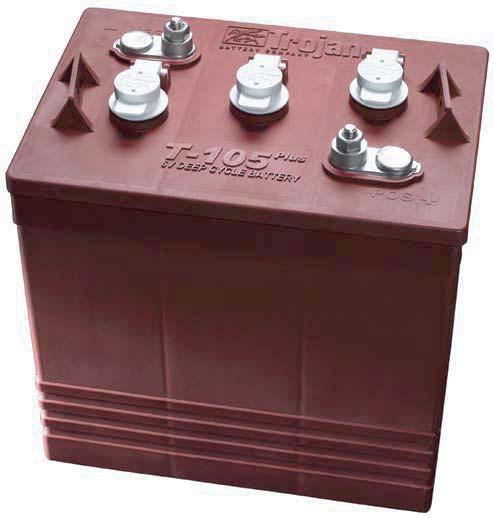
12 Uncrating machine Machine Preparation Carefully check the crate for any sign of damage. Batteries are in the unit. To uncrate the machine, remove banding from around the crate. Take off the top and sides And dispose of properly. Remove banding from machine. Remove the chocks around the drive wheels. Fold down ramp, and roll machine off of the base. Notify the carrier immediately if concealed damage is discovered. Connecting hoses Your machine is also equipped with two vacuum hoses which need to be connected for the dust control to work properly. 1. Turn all switches to the off position. 2. Hinge open the battery access lid to access the rear of the filter box and fan connections. 3. Check to see if hoses are clamped down to the shroud and the filter box securely. (you should not be able to pull them off easily) if hoses are loose tighten the hose clamp with a screwdriver. (see below) Connecting batteries Your machine is equipped with (six) 6 volt, Deep cycle batteries, which Form a 36 volt system. Maximum battery Dimensions are 7"w x 15"l x 15"h. 1. Turn all switches to the off position and remove key. 2. Hinge open the battery access lid to access the battery compartment. 3. All of the six battery cables are connected to the batteries. Locate any loose ones and connect to the open terminal. Tighten with 9/16" wrench. (see below) 4. Turn on main power switch and check the battery condition meter to ensure correct installation. Charge batteries if needed. (see: battery charging) 4. Check to see if hoses are clamped down to the shroud. Hose should have just enough slack to move up and down with the scrub deck and not interfere with other moving parts. (See below) Front PAGE 9
.")
 PAD 5.")
13 MACHINE SETUP ATTACHING PAD 1. Turn on machine power KEY SWITCH 2. Assure that the deck is raised to the up position by verifying that the uni-touch button is not depressed (A yellow ring will appear around the side of the uni-touch button). Turn machine power back off and remove key. (See right) 3. Remove blue big mouth from pad holder. BLUE BIG MOUTH PAD CLIP UNI-TOUCH BOTTON 4. Place pad on top of locking clip and slide both below burnishing deck directly into the center of one burnishing disk. (see below) PAD 5. With pad and clip directly in the center of the burnishing disk push up and screw in the pad clip. (Hand tighten only) (see below) 6. Run machine and check for vibraitons. If deck vibrates badly the pad may not be centered on disk correctly. Remove pad and reistall pad in the center of disk. BLUE BIG MOUTH PAD CLIP PAD SHROUD AND SHROIUD CURTAIN ***FOR CORRECT PAD APPLICATION, CALL YOUR LOCAL DEALER*** PAGE 10
 To check gauge push menu control button until battery gauge appears. Make sure batteries are fully charged before using.")
14 Operation Read and understand the safety section on page 5 and 6 before operating machine. Pre- burnishing Check list 1. Check battery condition gauge on the central command II LCD screen. (See below) To check gauge push menu control button until battery gauge appears. Make sure batteries are fully charged before using. LCD SCREEN MENU CONTROL Operating hints One Pass Burnishing Steps: (see below) 1. Turn machine on with the key switch. 2. Lower burnishing head to the floor by simply depressing the green "uni touch" button. 3. The dust control will activate automatically when you begin burnishing. 4. Begin burnishing by depressing the foot pedal slowly and then to the speed required, the headlight will illuminate. 6. Once the pad begins to move, check the pressure gauge. Start burnishing with in the green marks, do not use yellow marks without management approval. 7. To operate machine in reverse, simply switch the reverse switch to the reverse position, back up alarm will sound ( if equiped) and your speed is reduce to roughly 50% of forward speed. 2. Check condition of pad and make sure it is securely in place. 8. To stop the machine, let off the foot pedal, and the machine will stop automatically. 3. Check hose connections from filter box to fan and, from filter box to shroud. (See below) 5. Check condition of shroud curtain shroud curtain needs to be in good condition for dust control system to work properly. (See below) PAGE 11

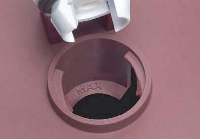
15 Battery charging Charger speccifications Output voltage of 36 volts. Output current of 25 amps max. Input voltage of 110 volts/60 Hz. Automatic shut off circuit. Made for deep cycle batteries. Danger: always charge batteries in a well ventilated area. Batteries emit hydrogen gas. Explosion or fire can result. Keep sparks and flame away. Shield eyes when servicing batteries and avoid contact with battery acid. Leave rear hood open when charging! 1. Transport machine to a well ventilated area for charging. 2. Turn the machine off. CAUTION: The following instructions are intended for the 36v charger supplied with the machine. Do not use any other charger with this machine. 3. Hinge opens the battery access hood to expose the batteries. (Caution: always wear eye protection when batteries are exposed) 4. Check the water level in each battery. Do not charge the machine unless the water is slightly higher than the plates. If needed, add enough distilled water to just slightly cover the plates. Do not over fill. Batteries can overflow during charging. Replace caps before charging. 5. With the grey charger plug disconnected from the machine, plug the charger power cord into a grounded 110 volt standard wall outlet. 6. Connect the grey charger plug into the battery charging port located on the lower portion of the steering tower. Gray charger plug 7. The charger will automatically begin charging, and automatically shut off when fully charged (check gauge) 8. After the charger has turned off, unplug the grey charger plug from the machine and disconnect the charger from the wall outlet. 9. Recheck the cell level after charging. If needed, add distilled water up to the correct level. Be certain to replace the caps securely and to wipe off the top of the batteries with a clean cloth. PAGE 12
16 Maintenance Daily Maintenance 1. Check pad condition. (Replace if necessary) 2. Check battery charge. 3. Clean dust control filters. 4. Check hoses and verify there are no clogs. 5. Check pads for wear and replace if needed. 6. Charge unit and verify that charger is operating properly Monthly Maintenance 1. Check flex driver 2. Check to see if battery cables are tightened and clean. (Tighten if needed) 3. Check parking brake 4. Check condition of burnishing deck actuator. 5. Check condition of burnishing deck drive belts Weekly Maintenance 1. Check battery water level. 2. Check condition of all three tires. Yearly Maintenance 1. Call your local dealer for yearly maintenance 3. Check condition of dust curtains on shroud. 4. Check condition of dust control hoses. 5. Check to see if vacuum exhaust is clear. PAGE 13
17 Preventative maintenance records CUSTOMER INFORMATION CUSTOMER ADDRESS CITY STATE ZIP CODE MACHINE INFORMATION MODEL # SERIAL # WORK ORDER# HOUR METER: BATTERY CONDITION Cell #1 Cell #2 Cell #3 Battery # 1 Hydrometer Reading Battery # 1 Water Condition Battery # 2 Hydrometer Reading Battery # 2 Water condition Battery # 3 Hydrometer Reading Battery # 3 Water Condition Battery # 4 Hydrometer Reading Battery # 4 Water condition Battery # 5 Hydrometer Reading Battery # 5 Water Condition Battery # 6 Hydrometer Reading Battery # 6 Water Condition Clean Battery Tops. Check Battery Cable and Terminal Condition NOTES: PAGE 14
18 Preventative maintenance records PAD CONDITION Pad Good Worn Needs Replacement Pad retainer Good Worn Needs Replacement Pad Holder Condition Good Worn Needs Replacement CLEAN AND/OR LUBRICATE IN SPEC REPAIR PROBLEM Burnishing Deck Linkage CHECK OPERATION AND CONDITION OF: IN SPEC REPAIR PROBLEM Steering wheel Tilt Mechanism Key Switch Horn Head Light LCD Display Page Button Pad Pressure Adjustment Foot Pedal Reverse Switch Back Up Alarm Burnish Switch Burnishing Deck Lift System Pad Motors & Motor Brushes Active Vacuum Switch Vacuum Motor performance Strobe Light Battery Charger Connectors Battery Charger VISUALLY INSPECT: IN SPEC REPAIR PROBLEM Vacuum Motor Brushes Vacuum Hoses Brush skirts Pad Motor Brushes Pad Drive Belt Condition & Tension Pad Driver Condition Drive Wheel Condition Rear Wheels Condition All Rollers PAGE 15
19 Preventative maintenance records COMMENTS Technician's Name Technician's Signature Date Customer's Name: Customer's Signature Date 2005 R.P.S. Corporation PAGE 16
20 LCD Screen Menu Displays SCREEN # 1 SCREEN # SCREEN #1 W/ERROR CODE 1 2 *** USE GREEN MENU SELECTION BUTTON ON CONTROL PANEL TO CHANGE SCREENS*** 7 1. Battery level indicator - indicates the energy level remaining in the batteries. (Shown on all menu displays) 2. Burnisher deck down pressure gauge - Indicates pressure on the burnishing pads. 3. Key switch hour meter - tells you the total hours the machine has been on. 4. Burnishing pad hour meter - tells you the total hours the burnishing motors have been used. 5. Transport hour meter - tells you the total hours the drive system has been used. 6. Vacuum/fan hour meter- Tells you the total hours the vacuum motor has been used. 7. Error warning symbol - indicates when there ius machine fault,- Displays diagnostic error code. 8. Diagnostic code - when the machine has detected an error it will display the warning symbol and a diagnostic code which indicates what's wrong. ( For common error codes and descriptions see page 18) PAGE 17
21 Troubleshooting Central Command NOTE: This machine is operated by a sophisticated electronic "controller" that has many fail-safes within it. The controller analyzes problems and displays a four-digit numeric code of what is wrong in the LCD window. Most of these codes require a technician's attention. You should not attempt repairs you are uncomfortable with, especially if you are not used to working on electronics. The complete list of codes is published in the simplified electronic trobleshooting manual, which is available to technical people. However, we have included the basic codes that you can usually resolve yourself ERROR. Parking brake circuit fault. Call a technician AND 7602 ERROR. Pad current over load. This can can occur when the pads hit a bump in the floor. To restart the pads, turn off the key and turn it on again. To avoid this error, either slow down on bumpy parts of the floor, or reduce downpressure on the pads ERROR. Voltage exceeds the maximum. Either the batteries are mis-wired, or the charger is still plugged into the machine , 7701, 7702, AND 7703 ERROR. The vacuum system has malfunctioned. Turn off key and turn on again to clear. If the code does not clear call a technician. PAGE 18
22 Troubleshooting Central Command AND 7901 ERROR. The emergency stop button is depressed. 6. HIGH THROTTLE ERROR. You pressed the drive button before turning on the key. Turn off the key, release the drive button and try again. 7. 2C00 AND 2C01 ERROR. Low voltage warning. Voltage has dropped down below the minimum required to operate the machine. If you wait a few minutes, the batteries may coast up a bit in voltage, allowing you to drive very slowly to the recharge station ERROR. The traction motor was used to climb a ramp, and was running up the ramp for more than the 60 seconds allowed for this. Turn off the key, turn on again, and continue. You should not use this machine to climb ramps so steep and so long that this code comes up repeatedly, or you could overheat the traction motor. 9. All other error codes. Turn off the key, and disconnect the positve battery cable from the batteries for more than one minute (the time is needed to drain the controller's on-board capacitor). Reconnect the cables, being sure that they are tight, if they are loose you will burn the battery cables or the battery. If you overtighten the cables you can damage the battery's lead terminal. 10. If the problem cannot be solved by any of these solution's call your local dealer's service department. PAGE 19
23 Trouble Shooting Problem Cause Solution No power, nothing operates. Burnishing motor does not operate. Faulty key switch. Batteries need charging. Faulty battery. Loose battery cable. Main circuit breaker tripped. Burnishing deck is not down. Foot pedal is not depressed. Burnishing circuit breaker tripped. Carbon brushes worn. Faulty motor or wires. See charging batteries. Replace battery. Tighten loose cable. Wait 5 minutes for auto reset. determine cause and correct. Put deck down. Engage foot pedal. Wait 5 minutes for auto reset Determine cause and correct. Drive motor does not operate. Recharge switch misadjusted. Faulty speed controller or wires. Faulty drive motor. Faulty wiring. Carbon brushes worn. Dust control fan does not operate. Faulty vacuum switch. Vacuum circuit breaker tripped. Faulty vacuum motor. Carbon brushes worn. Try operating "white " toggle. Wait 5 minutes for auto reset. Determine cause and correct. Drive motor runs incorrectly. Faulty speed controller or wires. Faulty potentiometer. Loose wires. PAGE 20
24 Trouble Shooting Problem Cause Solution Poor dust control. Poor burnishing quality. Burnishing scrub deck noisy. Rear tires noisy. Poor traction. Short run time. Main vacuum hose disconnected. Burnishing deck hose disconnected. Burnishing deck hose clogged. Damaged main vacuum hose. Damaged burnishing deck hose. Filter clogged. Filter door not closed tightly. Filter door gasket faulty. Filter full. Torn shroud curtain. Faulty vacuum Motor. Battery charge is low. Burnishing pads worn out. Debris stuck to burnishing pad. Torn burnishing pad. Faulty disk pad motor. Battery charge is low. Missing burnishing pad. Burnishing pad worn out. Torn curtain hitting burnishing disks. Damaged shroud. Bearings dry. Faulty hubs. Excessive burnishing pad. Pressure. Worn drive tire. Batteries run down. Batteries still down. Batteries low on water. Batteries over cycled. Reconnect hose. Reconnect hose. Remove debris. Clean out filters. Adjust screw on door clamp to tighten seal. Remove debris. Charge batteries overnight. Replace pads. Remove debris. Replace pads. Charge batteries overnight. Replace pads. Replace pads. Fix or replace shroud. Grease bearings. Reduce pressure with switch. Charge batteries twice Fill with distilled water to 3/4" above the lead plates. PAGE 21
25
26
27
Model 275. Operator Manual 275 Rider Burnisher Edition: 1
 Model 275 Operator Manual 275 Rider Burnisher 2010 Edition: 1 R.P.S. Corporation Phone: 1-800-450-9824 P.O. Box 241 Fax: 1-866-632-6961 Racine, Wisconsin 53401 How to use this manual This manual contains
PARTS MANUAL. Version BURNISHER. R.P.S. Corporation Phone: P.O. Box 241 Fax: Racine, Wisconsin 53401
 Version 3.0 PARTS MANUAL 275 BURNISHER R.P.S. Corporation Phone: 1-800-450-9824 P.O. Box 241 Fax: 1-866-632-6961 Racine, Wisconsin 53401 Front Panel... 4 Front Wheel Assembly... 6 Front Wheel Drive...
Version 1.0 OPERATOR MANUAL. R.P.S. Corporation Phone: P.O. Box 368 Fax: Racine, Wisconsin 53401
 Version 1.0 OPERATOR MANUAL T R S E R I E S R.P.S. Corporation Phone: 1-800-634-4060 P.O. Box 368 Fax: 1-866-901-3335 Racine, Wisconsin 53401 Safety Message... 4 Safety Precautions... 5 Maintenance...
Model 275. Operator and Parts Manual 275 Rider Burnisher
 Model 275 275 Burnisher Operator and Parts Manual 275 Rider Burnisher 2006 Edition: 1 R.P.S. Corporation Phone: 1-800-450-9824 P.O. Box 241 Fax: 1-866-632-6961 Racine, Wisconsin 53401 How to use this manual
Operating Instructions (EN) MODELS:
 MODELS:") Operating Instructions (EN) MODELS: 30'' Disk 34'' Disk 9'' Cylindrical 33'' Cylindrical Read these Instructions before using the machine. Read these Safety Messages before using the machine. Scan With
Operating Instructions (EN) MODELS: 30'' Disk 34'' Disk 9'' Cylindrical 33'' Cylindrical Read these Instructions before using the machine. Read these Safety Messages before using the machine. Scan With
Operating Instructions (EN)
") Operating Instructions (EN) Read these Instructions before using the machine. Read these Safety Messages before using the machine. Scan With Phone for more Information www.factorycat.com 7 South Street
Operating Instructions (EN) Read these Instructions before using the machine. Read these Safety Messages before using the machine. Scan With Phone for more Information www.factorycat.com 7 South Street
Operating Instructions (EN)
") INDUSTRIAL CLEANING EQUIPMENT Operating Instructions (EN) Read these Instructions before using the machine. Read these Safety Messages before using the machine. Scan With Phone for more Information www.factorycat.com
INDUSTRIAL CLEANING EQUIPMENT Operating Instructions (EN) Read these Instructions before using the machine. Read these Safety Messages before using the machine. Scan With Phone for more Information www.factorycat.com
Operating Instructions (EN) MODELS:
 MODELS:") Operating Instructions (EN) MODELS: 7'' Disk 0'' DIisk 5'' Cylindrical 0'' EDGE 4'' EDGE Read these Instructions before using the machine. Read these Safety Messages before using the machine. Scan With
Operating Instructions (EN) MODELS: 7'' Disk 0'' DIisk 5'' Cylindrical 0'' EDGE 4'' EDGE Read these Instructions before using the machine. Read these Safety Messages before using the machine. Scan With
Operating Instructions (EN)
") COMMERCIAL CLEANING EQUIPMENT Operating Instructions (EN) Read these Instructions before using the machine. Read these Safety Messages before using the machine. Scan With Phone for more Information www.tomcatequip.com
COMMERCIAL CLEANING EQUIPMENT Operating Instructions (EN) Read these Instructions before using the machine. Read these Safety Messages before using the machine. Scan With Phone for more Information www.tomcatequip.com
To Order Parts Call
 COMMERCIAL CLEANING EQUIPMENT Scan With Phone for more Information Operating Instructions (EN) Read these Instructions before using the machine. Read these Safety Messages before using the machine. www.tomcatequip.com
AUTOMATIC BURNISHER MODEL FURY 21 HSB
 AUTOMATIC BURNISHER MODEL FURY 21 HSB INTRODUCTION OPERATING & MAINTENANCE INSTRUCTIONS This operator s book has important information for the use and safe operation of this machine. Read this book carefully
Operating Instructions (EN)
") INDUSTRIAL CLEANING EQUIPMENT Operating Instructions (EN) Read these Instructions before using the machine. Read these Safety Messages before using the machine. Scan With Phone for more Information www.factorycat.com
INDUSTRIAL CLEANING EQUIPMENT Operating Instructions (EN) Read these Instructions before using the machine. Read these Safety Messages before using the machine. Scan With Phone for more Information www.factorycat.com
MAGNUM. Operating Instructions (EN) MODELS: 26'' DISK 28'' DISK 30'' DISK 34 DISK 24'' CYLINDRICAL 27'' CYLINDRICAL 30'' CYLINDRICAL 34'' CYLINDRICAL
 MODELS: 26'' DISK 28'' DISK 30'' DISK 34 DISK 24'' CYLINDRICAL 27'' CYLINDRICAL 30'' CYLINDRICAL 34'' CYLINDRICAL") MAGNUM Operating Instructions (EN) MODELS: 26'' DISK 28'' DISK 30'' DISK 34 DISK 24'' CYLINDRICAL 27'' CYLINDRICAL 30'' CYLINDRICAL 34'' CYLINDRICAL 28'' EDGE 32'' EDGE Read these Instructions before using
MAGNUM Operating Instructions (EN) MODELS: 26'' DISK 28'' DISK 30'' DISK 34 DISK 24'' CYLINDRICAL 27'' CYLINDRICAL 30'' CYLINDRICAL 34'' CYLINDRICAL 28'' EDGE 32'' EDGE Read these Instructions before using
PARTS MANUAL. Version BURNISHER. R.P.S. Corporation Phone: P.O. Box 241 Fax: Racine, Wisconsin 53401
 Version 3.0 PARTS MANUAL 275 BURNISHER R.P.S. Corporation Phone: 1-800-450-9824 P.O. Box 241 Fax: 1-866-632-6961 Racine, Wisconsin 53401 Front Panel... 4 Front Wheel Assembly... 6 Front Wheel Drive...
Operating Instructions (EN)
") Operating Instructions (EN) MODELS: 26'' Disk 30'' Disk 34'' Disk 24'' Cylindrical 27'' Cylindrical 30'' Cylindrical 34'' Cylindrical 28'' Orbital 32'' Orbital Read the Operators Manual before using the
Operating Instructions (EN) MODELS: 26'' Disk 30'' Disk 34'' Disk 24'' Cylindrical 27'' Cylindrical 30'' Cylindrical 34'' Cylindrical 28'' Orbital 32'' Orbital Read the Operators Manual before using the
Operating Instructions (EN) MODELS:
 MODELS:") Operating Instructions (EN) MODELS: 26'' Disk 28'' DIisk 25'' Cylindrical 29'' Cylindrical 24'' EDGE 28'' EDGE Read these Instructions before using the machine. Read these Safety Messages before using
Operating Instructions (EN) MODELS: 26'' Disk 28'' DIisk 25'' Cylindrical 29'' Cylindrical 24'' EDGE 28'' EDGE Read these Instructions before using the machine. Read these Safety Messages before using
Operating Instructions (EN)
") Operating Instructions (EN) MODELS: 17'' Disk Pad Assist 20'' Disk Pad Assist 23'' Disk Pad Assist 17'' Disk Traction 20'' Disk Traction 23'' Disk Traction 26'' Disk Traction 28'' Disk Traction 24'' Cylindrical
Operating Instructions (EN) MODELS: 17'' Disk Pad Assist 20'' Disk Pad Assist 23'' Disk Pad Assist 17'' Disk Traction 20'' Disk Traction 23'' Disk Traction 26'' Disk Traction 28'' Disk Traction 24'' Cylindrical
HOW TO USE THIS MANUAL
 HOW TO USE THIS MANUAL This manual contains the following sections: - HOW TO USE THIS MANUAL - SAFETY - OPERATIONS - MAINTENANCE - PARTS LIST The HOW TO USE THIS MANUAL section will tell you how to find
PARTS MANUAL. Version BURNISHER. R.P.S. Corporation Phone: P.O. Box 241 Fax: Racine, Wisconsin 53401
 Version 13.0301 PARTS MANUAL 255 BURNISHER R.P.S. Corporation Phone: 1-800-450-9824 P.O. Box 241 Fax: 1-866-632-6961 Racine, Wisconsin 53401 Front Wheel Assembly...4 Wheels and Rollers...6 Rear Axle and
5100 Automatic Battery Scrubber
 5100 Automatic Battery Scrubber This manual is furnished with each new model. It provides necessary operation and maintenance instructions. Read this manual completely and understand the machine before
NILFISK BA 500 Service Manual
 NILFISK BA 500 Service Manual Model 66324400 12/94 Form Number 043023 TABLE OF CONTENTS Batteries...21 Brush Drive Belt Adjustment Or Replacement...7 Brush Drive Motor - Carbon brush Inspection... 8 Brush
Model Operator Manual
 Model Operator Manual Series 2009 Version 3.0 R.P.S. Corporation Phone: 1-800-634-4060 Mailing: P.O. Box 368 Fax: 1-866-901-3335 Racine, Wi. 53401 Shipping: 1711 South st. Racine, Wi. 53404 HOW TO USE
Service Manual. For the SCV2832E, SCV2426, Automatic Scrubbers For: Training Troubleshooting
 Service Manual For the SCV2832E, SCV2426, SCV280000 & ES2832 Automatic Scrubbers For: Training Troubleshooting Adjustments Contents 1 Cautions ----------------------------------------------------------------------
MACHINE DATA TABLE OF CONTENTS
 This manual is furnished with each new TENNANT Speedscrub Model. It provides necessary operation and machine care instructions. Read this manual completely and understand the machine before operating or
Operating Instructions (EN)
") Operating Instructions (EN) MODELS: 26'' Disk 30'' Disk 34'' Disk 24'' Cylindrical 27'' Cylindrical 30'' Cylindrical 34'' Cylindrical 28'' Orbital 32'' Orbital Read the Operators Manual before using the
Operating Instructions (EN) MODELS: 26'' Disk 30'' Disk 34'' Disk 24'' Cylindrical 27'' Cylindrical 30'' Cylindrical 34'' Cylindrical 28'' Orbital 32'' Orbital Read the Operators Manual before using the
Lumina 28 Traction Drive Model: Battery Burnisher M28036TDQP OPERATION SERVICE PARTS CARE
 Lumina 28 Traction Drive Model: Battery Burnisher M28036TDQP OPERATION SERVICE PARTS CARE Table of Contents IMPORTANT SAFETY INSTRUCTIONS...1 OPERATING INSTRUCTIONS...2 INSPECTION...2 ELECTRICAL...2 BATTERIES...2
MICROMINI. Operating Instructions (EN) MODELS: 20'' EDGE 24'' EDGE. Read these Instructions before using the machine.
 MODELS: 20'' EDGE 24'' EDGE. Read these Instructions before using the machine.") MICROMINI Operating Instructions (EN) MODELS: 20'' EDGE 24'' EDGE Read these Instructions before using the machine. Read these Safety Messages before using the machine. www.rpscorporation.com www.factorycat.com
MICROMINI Operating Instructions (EN) MODELS: 20'' EDGE 24'' EDGE Read these Instructions before using the machine. Read these Safety Messages before using the machine. www.rpscorporation.com www.factorycat.com
FLOORMASTER 18B OPERATING & MAINTENANCE READ THIS BOOK
 FLOORMASTER 18B INTRODUCTION OPERATING & MAINTENANCE INSTRUCTIONS This operator s book has important information for the use and safe operation of this machine. Read this book carefully before starting
MM185 Rev. 11 (9-94)
") 465 480 490 MM85 Rev. (9-94) This manual is furnished with each new TENNANT Model 465, 480, and 490. It provides necessary operating and preventive maintenance instructions. Read this manual completely
465 480 490 MM85 Rev. (9-94) This manual is furnished with each new TENNANT Model 465, 480, and 490. It provides necessary operating and preventive maintenance instructions. Read this manual completely
MAGNUM MAGNUM SERIES. Operator Manual. Version /19/08
 MAGNUM SERIES MAGNUM Operator Manual Version 4.0 02/19/08 R.P.S. Corporation Phone: 1-800-450-9824 P.O. Box 241 Fax: 1-866-632-6961 Racine, Wisconsin 53401 HOW TO USE THIS MANUAL This manual contains the
Sentry Carpet Maintainer. Operator and Parts Manual. Model No.: PAC Rev. 00 (09-99) Patent No.
 Patent No.") Sentry 2300 Patent No. : 5,611,106 Carpet Maintainer Model No.: 608660 608661 - PAC Operator and Parts Manual NOBLES 12875 RANSOM STREET HOLLAND MI 49424 U.S.A. CUSTOMER SERVICE: 1-800-365-6625 FAX: 1
Sentry 2300 Patent No. : 5,611,106 Carpet Maintainer Model No.: 608660 608661 - PAC Operator and Parts Manual NOBLES 12875 RANSOM STREET HOLLAND MI 49424 U.S.A. CUSTOMER SERVICE: 1-800-365-6625 FAX: 1
Retriever 4600 OPERATOR MANUAL Advance MODEL
 Retriever 4600 OPERATOR MANUAL Advance MODEL 56416000 9/97 revised 7/00 Form Number 56041389 TABLE OF CONTENTS Page Introduction...2 Parts and Service...2 Nameplate...2 Uncrating the Machine...2 Cautions
USER MANUAL. Ride-on Scrubbers. Model # Serial No.# READ USER MANUAL CAREFULLY BEFORE USE. Please fill out & return your warranty card
 Ride-on Scrubbers USER MANUAL READ USER MANUAL CAREFULLY BEFORE USE Please fill out & return your warranty card Model # Serial No.# VIPER INDUSTRIAL ESTATE LIANG BIAN, LIAO BU DONGGUAN, GUANGDONG CHINA
CHARGER DB (Wheel Drive)
") OPERATION MANUAL CHARGER DB (Wheel Drive) IMPORTANT SAFETY INSTRUCTIONS WARNING: Failure to observe these instructions can cause personal injury to machine operator or bystanders. WARNING: Fire or explosion
OPERATION MANUAL CHARGER DB (Wheel Drive) IMPORTANT SAFETY INSTRUCTIONS WARNING: Failure to observe these instructions can cause personal injury to machine operator or bystanders. WARNING: Fire or explosion
NSS HIGH-SPEED BATTERY BURNISHERS
 OPERATION MANUAL NSS HIGH-SPEED BATTERY BURNISHERS IMPORTANT SAFETY INSTRUCTIONS WARNING: Failure to observe these instructions can cause personal injury to machine operator or bystanders. WARNING: Fire
before serial number 2214
 before serial number 2214 Contents Page Safety Rules... 3 Pre-operational & Safety Inspection... 4 Operating Instructions... 6 Transport... 12 Maintenance & Routine Service... 12 Specifications... 14 SAFETY
AUTOMATIC SCRUBBER. Read these instructions before using the machine MODELS: SCC172 QSCC172 SCH
 AUTOMATIC SCRUBBER MODELS: SCC172 QSCC172 SCH172 10066320 10066300 86218900 SCHC172 HCC172 QSCC172IA 10066330 10066270 10066310 QSCC172IS AS17 AS17B 10066080 10066210 10066220 AS17T AS17TH AS17E 10066250
iscrub 20 Operating instructions (ENG) MODELS: CS CSC CSX CSXC CS22SP CSC22SP
 MODELS: CS CSC CSX CSXC CS22SP CSC22SP") iscrub 0 Operating instructions (ENG) MODELS: CS0 00650 CSC0 006330 CSX0 006370 CSXC0 006380 CSSP 006300 CSCSP 006340 Read these instructions before using the machine. 863330-AM 0/0/ Machine Data Log/Overview
iscrub 0 Operating instructions (ENG) MODELS: CS0 00650 CSC0 006330 CSX0 006370 CSXC0 006380 CSSP 006300 CSCSP 006340 Read these instructions before using the machine. 863330-AM 0/0/ Machine Data Log/Overview
User Manual. Max Ride 26 Rider Scrubber Disc Traction Drive
 User Manual Max Ride 26 Rider Scrubber Disc Traction Drive Preface Preface This manual is furnished with each new MINUTEMAN Max Ride 26. This provides the necessary operating and preventive maintenance
S10 PEDESTRIAN SWEEPER OPERATOR MANUAL
 S10 PEDESTRIAN SWEEPER OPERATOR MANUAL Clemas & Co. Unit 5 Ashchurch Business Centre, Alexandra Way, Tewkesbury, Gloucestershire, GL20 8NB. Tel: 01684 850777 Fax: 01684 850707 Email: info@clemas.co.uk
Installation, Operation & Maintenance Manual
 Installation, Operation & Maintenance Manual Picture may differ from your specific application For Pro-Fill kits with part numbers beginning in BG BL-175 9-20-13 General Information & Precautions This
BR 2250/BR Burnisher. Operator and Parts Manual
 BR 0/BR 00 Burnisher Model No.: 60834 BR-0 608343 BR-0 Pac 60948 BR-0 Can. Pac 608340 BR-00 60834 BR-00 Pac 60947 BR-00 Can. Pac Operator and Parts Manual NOBLES 87 RANSOM STREET HOLLAND MI 4944 U.S.A.
Installation, Operation & Maintenance Manual. For Pro-Fill kits with part numbers beginning in BG
 Installation, Operation & Maintenance Manual For Pro-Fill kits with part numbers beginning in BG BL-175 6/26/2009 General Information & Precautions This publication provides detailed instructions for installing
Electronic Service Manuals
 Electronic Service Manuals This electronic document is provided as a service to our customers. We do not create the contents of the information contained in this document. Should you have detailed questions
BATTERY & STARTER ANALYSER (BSA-12) User Manual
 User Manual") BATTERY & STARTER ANALYSER (BSA-12) User Manual Introduction BSA-12 Battery Starter Analyser does not carry internal batteries but is powered up from external DC source ranging from 9V to 15V DC. It is
BATTERY & STARTER ANALYSER (BSA-12) User Manual Introduction BSA-12 Battery Starter Analyser does not carry internal batteries but is powered up from external DC source ranging from 9V to 15V DC. It is
SOLO VACUUM OPERATING & MAINTENANCE
 SOLO VACUUM INTRODUCTION OPERATING & MAINTENANCE INSTRUCTIONS This operator s book has important information for the use and safe operation of this machine. Read this book carefully before starting the
SpeedGleam /Plus. 36 Volt Dust Control Burnisher. Operator and Parts Manual
 SpeedGleam /Plus 36 Volt Dust Control Burnisher Model No.: 608525 SpeedGleam 608526 SpeedGleam Pac. 609251 SpeedGleam Pac. Can. 608344 SpeedGleam Plus 608345 SpeedGleam Plus Pac. 609252 SpeedGleam Plus
INSTRUCTIONS AND WARRANTY FOR THE STAND AID MODEL 1501 STAND AID SERIAL #
 MAKERS OF STAND AID, PTA, FREEDOM CHAIR STAND AID MODEL 1501 PO BOX 386 Sheldon, IA 51201 1-800-831-8580 1-712-324-2153 (In Iowa) Fax: 712-324-5210 www.stand-aid.com INSTRUCTIONS AND WARRANTY FOR THE STAND
INSTRUCTIONS AND WARRANTY FOR THE STAND AID MODEL 1501 STAND AID SERIAL #
 MAKERS OF STAND AID AND ROLL AID STAND AID MODEL 1501 PO BOX 386 Sheldon, IA 51201 1-800-831-8580 1-712-324-2153 (In Iowa) Fax: 712-324-5210 INSTRUCTIONS AND WARRANTY FOR THE STAND AID MODEL 1501 STAND
Installation Operation Parts
 OWNER S MANUAL BATTERY BACKUP SUMP Installation Operation Parts For further operating, installation or maintenance assistance, Call 98-8-05 PRINTED IN U.S.A. M-8 (/9) RULES FOR SAFE INSTALLATION AND OPERATION
ivacuum 34 Operating instructions (ENG) CV34X Read these instructions before using the machine T 02/09/12
 CV34X Read these instructions before using the machine T 02/09/12") ivacuum 34 Operating instructions (ENG) MODELS: CV34 10125650 CV34X 10125790 Read these instructions before using the machine. 86347810-T 02/09/12 Machine Data/Overview OVERVIEW The Chariot ivacuum 34
ivacuum 34 Operating instructions (ENG) MODELS: CV34 10125650 CV34X 10125790 Read these instructions before using the machine. 86347810-T 02/09/12 Machine Data/Overview OVERVIEW The Chariot ivacuum 34
HSB21 Battery Burnisher
 HSB21 Battery Burnisher OPERATION AND PARTS MANUAL Rev A 01/2003 HS2100 PARTS LIST Item No. Qty Part No. Description 1 1 001 Lower Body Housing 2 1 002 Battery Condition Meter 3 1 003 RPM Meter 4 1 004
Service Manual. Extractor Model XR28QP. For The. For: Troubleshooting Adjustments
 Service Manual For The X Ride 28 Rider Extractor Model XR28QP For: Training Troubleshooting Adjustments Contents 1 Cautions ------------------------------------------------------------------------------
EW-52. Owner s Manual. (888) Customer Service (888) Service
 Customer Service (888) Service") EW-52 Owner s Manual www.ewheelsdealers.com (888) 305-0881 Customer Service (888) 571-2845 Service 0 Table of Contents 1. Instrument Panel. 2 2. Music system operation. 3 3. Before you operate your scooter....
EW-52 Owner s Manual www.ewheelsdealers.com (888) 305-0881 Customer Service (888) 571-2845 Service 0 Table of Contents 1. Instrument Panel. 2 2. Music system operation. 3 3. Before you operate your scooter....
- Optional Audio warning when discharge test is complete or tester malfunction.
 INTRODUCTION Congratulations on acquiring your new LT360 battery discharge tester. The LT360 battery discharge tester has been designed to provide the operator with accurate battery discharge testing and
B10 Rider Burnisher * * English EN Operator Manual. North America / International. QA Controls Supervisor Settings TennantTrue Parts
 B10 Rider Burnisher English EN Operator Manual QA Controls Supervisor Settings TennantTrue Parts To view, print or download the latest manual, visit: www.tennantco.com/manuals North America / International
1500 & 2000 RPM BURNISHERS
 1500 & 2000 RPM BURNISHERS INTRODUCTION OPERATING & MAINTENANCE INSTRUCTIONS This operator s book has important information for the use and safe operation of this machine. Read this book carefully before
Concorde HP Plus. Automatic Carpet Extractor. Operator and Parts Manual. Model No.: Pac Can. Pac Rev.
 Concorde HP Plus Automatic Carpet Extractor Model No.: 608349 60893 Pac 60926 Can. Pac Operator and Parts Manual NOBLES 1287 RANSOM STREET HOLLAND MI 49424 U.S.A. CUSTOMER SERVICE: 1-800-36-662 FAX: 1
TO ORDER PARTS CALL: (479) or
 or") Owner s Manual Industrial Ergonomic User-Friendly Hand Controls Date Manufactured: / / o Mart Cart XTi 24 Model 03522 - SKU# 280-3522 o Mart Cart XTi 24 Model 03524 - SKU# 280-3524 CONGRATULATIONS You
Owner s Manual Industrial Ergonomic User-Friendly Hand Controls Date Manufactured: / / o Mart Cart XTi 24 Model 03522 - SKU# 280-3522 o Mart Cart XTi 24 Model 03524 - SKU# 280-3524 CONGRATULATIONS You
SPEEDGLEAM RIDER * * OPERATOR MANUAL RIDER BURNISHER. QA Controls Supervisor Settings Rev. 00 ( ) ENGLISH
 ENGLISH") ENGLISH QA Controls Supervisor Settings SPEEDGLEAM RIDER RIDER BURNISHER OPERATOR MANUAL To view, print or download the latest manual, visit: www.nobles.com/manuals www.nobles.com/manuals 9010727 Rev.
ENGLISH QA Controls Supervisor Settings SPEEDGLEAM RIDER RIDER BURNISHER OPERATOR MANUAL To view, print or download the latest manual, visit: www.nobles.com/manuals www.nobles.com/manuals 9010727 Rev.
SCRUBBER. Operating Instructions FLXSP3 FLXSP3T FLX3T. Read these instructions before using the machine IPX /19/03
 SCRUBBER Operating Instructions MODELS: FLX3 FLX3T FLXSP3 FLXSP3T IPX4 Read these instructions before using the machine D 980087 07/19/03 MACHINE DATA LOG/OVERVIEW MODEL DATE OF PURCHASE SERIAL NUMBER
OWNER S MANUAL and TECHNICAL DOCUMENTATION
 IMPORTANT DOCUMENT - DELIVER TO MANAGER Quality, Performance, Value OWNER S MANUAL and TECHNICAL DOCUMENTATION MODELS 280-4036, 280-4037, 280-4063 FOR UL (Underwriter Laboratories) APPROVED CARTS Mart
EAVERLINE. Operator s Manual. Series 5 Feed Cart Models 521, 525, 531 & 537. Weaverline, LLC - Churchtown, PA 17555
 EAVERLINE Operator s Manual Series 5 Feed Cart Models 521, 525, 531 & 537 CAUTION: Drive at a speed slow enough to ensure safety and complete control at all times. CAUTION: Know the controls and how to
290/350 SERIES. Operating Instructions & Parts Manual (EN) Read these Instructions before using the machine.
 Read these Instructions before using the machine.") 290/350 SERIES Operating Instructions & Parts Manual (EN) Read these Instructions before using the machine. Read these Safety Messages before using the machine. www.rpscorporation.com www.factorycat.com
290/350 SERIES Operating Instructions & Parts Manual (EN) Read these Instructions before using the machine. Read these Safety Messages before using the machine. www.rpscorporation.com www.factorycat.com
SR5730. INSTRUCTIONS FOR USE Models , , /08 FORM NO
 SR5730 INSTRUCTIONS FOR USE Models 505-945, 505-946, 505-959 5/08 FORM NO. 56041764 TABLE OF CONTENTS Introduction... 4 Cautions and Warnings... 5 Symbols... 6 Specifications... 8-9 Machine Preparation...
Parts Manual E 24 Walk-Behind Scrubber
 Parts Manual E 24 Walk-Behind Scrubber 2 Table Of Contents Chassis Part I...4 Lift Pedal Assembly...6 Chassis Part II...8 Traction Drive...10 Chassis Part III...12 Water Supply Part I...14 Recovery Tank
OPERATORS MANUAL/INSTRUCTIONS/PARTS & SERVICE FOR MANUAL & ELECTRIC
 OPERATORS MANUAL/INSTRUCTIONS/PARTS & SERVICE FOR MANUAL & ELECTRIC TABLE OF CONTENTS SAFETY DELIVERY INSPECTION OPERATION 4 MAINTENANCE 5 TROUBLE SHOOTING 5 PARTS 6-15 Frame Scissor Assembly 6-7 Thrust
INSTRUCTION MANUAL. Rescue Ride-On SKY Ver. 5
 Ver. 5 INSTRUCTION MANUAL Rescue Ride-On SKY2886 + 3995 SAFETY Please retain these instructions for future reference. This vehicle must be assembled by an adult who has read and understood the instructions
Air-Operated Waste Oil Drainer
 Air-Operated Waste Oil Drainer 20-Gallon Tank Owner s Manual WARNING: Read carefully and understand all ASSEMBLY AND OPERATION INSTRUCTIONS before operating. Failure to follow the safety rules and other
STEP-BY-STEP INSTALLATION GUIDE
 Battery Backup System STEP-BY-STEP INSTALLATION GUIDE Operating Instructions & Parts Manual ESP25 Please read and save these instructions. Read carefully before attempting to assemble, install, operate
User Manual. PHX26ECO Walk-Behind Scrubber Traction Drive Disc Deck
 User Manual PHX26ECO Walk-Behind Scrubber Traction Drive Disc Deck This manual is furnished with each new POWERBOSS PHX26ECO. This provides the necessary operating and preventive maintenance instructions.
iscrub 20 Operating instructions (ENG) MODELS: CS CSC CSX CSXC
 MODELS: CS CSC CSX CSXC") iscrub 0 Operating instructions (ENG) MODELS: CS0 00650 CSC0 006330 CSX0 006370 CSXC0 006380 Read these instructions before using the machine. 863330-AJ 0/4/ Machine Data Log/Overview OVERVIEW The Chariot
iscrub 0 Operating instructions (ENG) MODELS: CS0 00650 CSC0 006330 CSX0 006370 CSXC0 006380 Read these instructions before using the machine. 863330-AJ 0/4/ Machine Data Log/Overview OVERVIEW The Chariot
Operator and Parts Manual 297 Rider Sweeper
 297 SERIES Operator and Parts Manual 297 Rider Sweeper Mid-Central Corporation Phone: 1-800-450-9824 P.O. Box 241 Fax: 1-866-632-6961 Racine, Wisconsin 53401 www.tomcatequip.com 297 RIDER SWEEPER THE TOMCAT
Go Yonder D-Lite Owner s Manual
 Go Yonder D-Lite Owner s Manual Marketed in Australia and New Zealand by Bzooma Pty Ltd ABN 37 640 907 507 TABLE OF CONTENTS Table of Contents... 1 Bzooma Pty Ltd... 1 Introduction... 1 Operation... 1
Audi R8. Ride-on Car 5F62630 OWNER S MANUAL. Keep instructions for future reference
 Audi R8 Ride-on Car 5F62630 OWNER S MANUAL Keep instructions for future reference 1 Safety The owner s manual contains assembly, use and maintenance instructions. The vehicle must be assembled by an adult
INSTRUCTION MANUAL. Ride-On Convertible Truck SKY SKY SKY2581. Ver. 2
 Ver. 2 INSTRUCTION MANUAL Ride-On Convertible Truck SKY2069 + SKY2338 + SKY2581 SAFETY Please retain these instructions for future reference. This vehicle must be assembled by an adult who has read and
EW-27 Crossover Pre-Mobility Scooter
 EW-27 Crossover Pre-Mobility Scooter Owner s Manual www.ewheelsdealers.com Before (888) 305-0881 you operate Customer the Service scooter (888) 571-2845 Service 0 Locate the below listed materials in rear
Car Battery Charger Instructions for Use
 BATTERY CHARGER 12Volt 4Amp FOR INDOOR USE ONLY Power Details: Input: 230-240Vac; 50Hz; 52W Output: 12V DC; 2.8A Maximum Charge Rate: 4A RMS Read these instructions before operating this car battery charger
User Manual. H20 Walk-Behind Scrubber Disc Traction Drive
 User Manual H20 Walk-Behind Scrubber Disc Traction Drive This manual is furnished with each new MINUTEMAN H20. This provides the necessary operating and preventive maintenance instructions. Operators must
EW-04. Owner s Manual. ewheels Service (888)
") EW-04 Owner s Manual ewheels Service (888) 571-2845 0 Table of Contents Page 2 - Feature Guide Page 3 - Technical Specifications Page 4 - Operation of Scooter Page 8 - Folding Instructions Page 9 - Charging
EW-04 Owner s Manual ewheels Service (888) 571-2845 0 Table of Contents Page 2 - Feature Guide Page 3 - Technical Specifications Page 4 - Operation of Scooter Page 8 - Folding Instructions Page 9 - Charging
User Manual. Phoenix 20 Floor Scrubber Traction Drive
 User Manual Phoenix 20 Floor Scrubber Traction Drive This manual is furnished with each new PowerBoss Phoenix 20. This provides the necessary operating and preventive maintenance instructions. Operators
MOTORIZED FOLDING CAMPER WINCH
 OWNER'S MANUAL MOTORIZED FOLDING CAMPER WINCH With 1200lb Lift Capacity The 12 Volt Motorized Folding Camper Winch is used to raise and lower folding campers with the touch of the switch, eliminating hand
Deep Cycle Battery Safety. First. Battery Handling, Maintenance & Test Procedures
 Deep Cycle Battery Safety. First. Battery Handling, Maintenance & Test Procedures Crown deep cycle batteries employ a low-maintenance design. They do require periodic maintenance and effective charging
IMPORTANT SAFETY INSTRUCTIONS IMPORTANT: READ AND SAVE THIS SAFETY AND INSTRUCTION MANUAL. KEEP IT WITH OR NEAR CHARGER AT ALL TIMES.
 IMPORTANT SAFETY INSTRUCTIONS IMPORTANT: READ AND SAVE THIS SAFETY AND INSTRUCTION MANUAL. KEEP IT WITH OR NEAR CHARGER AT ALL TIMES. SPECIFICATIONS: For technical assistance, call your Dealer with the
ACCUSENSE CHARGE SERIES ON/OFF BOARD FULLY AUTOMATIC BATTERY CHARGER
 ACCUSENSE CHARGE SERIES ON/OFF BOARD FULLY AUTOMATIC BATTERY CHARGER SPECIFICATIONS: *Photo for reference only* Part number 8890439 Mode Select: Selects Battery Type Refer to Section 6. IMPORTANT: READ
User s Manual. Automatic Switch-Mode Battery Charger
 User s Manual Automatic Switch-Mode Battery Charger IMPORTANT Read, understand, and follow these safety rules and operating instructions before using this battery charger. Only authorized and trained service
T3e Automatic Scrubber
 ENGLISH T3e Automatic Scrubber Operator Manual The Safe Scrubbing Alternativer International www.tennantco.com 1033579 Rev. 03 (11-2008) *1033579* This manual is furnished with each new model. It provides
Mini Pump Installation, Operation & Maintenance Manual. For Models: BA-MS-633
 Mini Pump Installation, Operation & Maintenance Manual For Models: BA-MS-633 BL-309 6/08/2012 General Information & Precautions This publication provides detailed instructions for installing the single
24 VOLT AUTOMATIC BATTERY CHARGER PART NO
 24 VOLT AUTOMATIC BATTERY CHARGER PART NO. 957732 AC Input: DC Output: Battery Type: Specifications 230 volts, 50 hertz, 3.5 amps, single-phase 24 volts, 20 amps initially tapering to 6 amps 24 volt, 12
Hydraulic Immediate Need Power Pack
 Safety, Operation, and Maintenance Manual WARNING Improper use of this tool can result in serious bodily injury This manual contains important information about product function and safety. Please read
B5/B7 Walk-Behind Battery Burnisher
 B5/B7 Walk-Behind Battery Burnisher English EN Operator Manual TennantTrue Parts North America / International www.tennantco.com For the latest Parts manuals and other language Operator manuals, visit:
Model #: ES320 Floor Scrubber Traction Driven E320QP E320CE E320QPIW OPERATION SERVICE PARTS CARE
 ES320 Floor Scrubber Traction Driven Model #: E320QP E320CE E320QPIW OPERATION SERVICE PARTS CARE TABLE OF CONTENTS IMPORTANT SAFETY INSTRUCTIONS...1 FOR SAFETY DURING OPERATION:...1 FOR SAFETY WHEN SERVICING
INSTRUCTION MANUAL. Ride-On Convertible SKY907 + SKY908 + SKY2308. Ver. 3
 Ver. 3 INSTRUCTION MANUAL Ride-On Convertible SKY907 + SKY908 + SKY2308 SAFETY Please retain these instructions for future reference. This vehicle must be assembled by an adult who has read and understood
EW-66. Owner s Manual. (888) Customer Service Table of Contents (888) Service
 Customer Service Table of Contents (888) Service") EW-66 Owner s Manual www.ewheelsdealers.com (888) 305-0881 Customer Service Table of Contents (888) 571-2845 Service 0 Table of Contents 1. Before you operate your scooter...... 2 2. Scooter initial operation......
EW-66 Owner s Manual www.ewheelsdealers.com (888) 305-0881 Customer Service Table of Contents (888) 571-2845 Service 0 Table of Contents 1. Before you operate your scooter...... 2 2. Scooter initial operation......
Model: SE-4020-CA Automatic Battery Charger
 OWNERS MANUAL Model: SE-4020-CA Automatic Battery Charger PLEASE SAVE THIS OWNERS MANUAL AND READ BEFORE EACH USE. This manual will explain how to use the battery charger safely and effectively. Please
Innovatech User Manual. Predator 2400 T H E S U R F A C E P R E P A R A T I O N S P E C I A L I S T S
 Innovatech User Manual Predator 2400 T H E S U R F A C E P R E P A R A T I O N S P E C I A L I S T S CONTENTS Introduction... 3 Delivery... 3 Grinder Specifications... 4 Safety Warning... 4 Controls and
CHARGER DB (Wheel Drive)
") OPERATION MANUAL CHARGER DB (Wheel Drive) IMPORTANT SAFETY INSTRUCTIONS WARNING: Failure to observe these instructions can cause personal injury to machine operator or bystanders. WARNING: Fire or explosion
OPERATION MANUAL CHARGER DB (Wheel Drive) IMPORTANT SAFETY INSTRUCTIONS WARNING: Failure to observe these instructions can cause personal injury to machine operator or bystanders. WARNING: Fire or explosion
SAVE THESE INSTRUCTIONS
 OPERATION MANUAL WARHORSE IMPORTANT SAFETY INSTRUCTIONS WARNING: Failure to observe these instructions can cause personal injury to machine operator or bystanders. WARNING: Asphyxiation Hazard. An improperly
EW-09. Owner s Manual. (888) Customer Service. (888) Service
 Customer Service. (888) Service") EW-09 Owner s Manual www.ewheelsdealers.com (888) 305-0881 Customer Service (888) 571-2845 0 Service Table of Contents Page 2 - Feature Guide Page 3 - Product Specifications Page 4 - Operation of Scooter
EW-09 Owner s Manual www.ewheelsdealers.com (888) 305-0881 Customer Service (888) 571-2845 0 Service Table of Contents Page 2 - Feature Guide Page 3 - Product Specifications Page 4 - Operation of Scooter
Owner s Manual and Assembly Instructions
 RollPlay 6V Mini Quad Owner s Manual and Assembly Instructions Model #: ACQUAD-P, ACQUAD-CAM, ACQUAD Read and understand the entire manual before assembly and operation. The vehicle must be assembled by