Skippi plus. Instructions for Use
|
|
|
- Wendy Thompson
- 5 years ago
- Views:
Transcription
1 Instructions for Use
2 Additional options for the The power wheelchair can be equipped with the following additional options (applicable options are checked): Electronic drive-away lock* [ ] Function enabled [ ] Function disabled If enabled, the function is activated by pressing the mode button on the control panel. The function is deactivated with the joystick. Electronic steering lock* [ ] Function enabled [ ] Function disabled 2-way adapter cable* [ ] Adapter cable included [ ] Adapter cable not included The included adapter cable allows the following functions to be selected directly through separate buttons: [ ] Footrest, left [ ] Footrest, right [ ] Seat tilt [ ] Seat height adjustment [ ] Back angle adjustment [ ] Light [ ] Direction indicator, right [ ] Direction indicator, left [ ] Horn [ ] Warning flasher [ ] other: *See the Accessories chapter for more information.
3 Table of Contents Table of Contents 1 General Information Foreword Intended Use Area of Application Service Safety Explanation of Symbols Standards and directives General Safety Instructions Safety requirements for transportation, storage and assembly Safety requirements for operation Safety requirements for care, maintenance and disposal Safety functions Warning Symbols and Type Plates Product description Delivery and preparation for use Delivery Initial operation Transportation and Storage Transport in a Motor Vehicle for the Disabled Disassembling the power wheelchair Storage Operation Adjustment Options Backrest Seat angle Side panel with armrest Control Panel Footrest Getting In and Out From the side From the front Control unit Control Panel Separate LCD monitor Switching on and off Driving function Battery Capacity indicator Ottobock 3
4 Table of Contents Controlling additional electrical functions Drive-away lock Releasing and engaging the wheel lock Batteries Charging Charger Charging Process Accessories Attendant control Functional overview Special controls Electric seat options Seat height adjustment Electric seat tilt Electric back angle adjustment Mechanically elevating footrests Push-button module x adapter cable for Piko or Buddy button Other Display and Control Elements Separate LCD monitor with infrared Control panel holder Ottobock Swing-away control panel holder with removable control panel Lap belt Additional options Malfunctions / troubleshooting Warning Fault Fault indication: Control panel / LCD display Fault indication: Attendant control Defect / failure Maintenance and Care Maintenance intervals Replace the fuses Replacing the tyres/inner tubes Cleaning and Care Disinfection Technical data Disposal Information on Re-Use Liability CE Conformity... 91
5 Table of Figures Table of Figures Fig. 1 Main components Fig. 2 Anti-tipper / plug with battery cable Fig. 3 Backrest folded down Fig. 4 Removed battery packs Fig. 5 Rear eyebolts, front eyebolts Fig. 6 Removing the footrest Fig. 7 Removing the control panel Fig. 8 Removing the side panels Fig. 9 Folding the back rest down Fig. 10 Releasing the seat lock Fig. 11 Removing the battery packs Fig. 12 Push the step points (frame protection rollers) down Fig. 13 Lifting / removing the frame Fig. 14 Loosen the height-adjustable push handles Fig. 15 Release strap for the backrest Fig. 16 Loosen the Allen head screws Fig. 17 Removing the side panel Fig. 18 Adapting the armrest to the upper arm length.. 37 Fig. 19 Adapting the armrests to the forearm length Fig. 20 Removing the control panel Fig. 21 Removal for a swing-away control panel holder Fig. 22 Adapting the control panel Fig. 23 Footrest latch Fig. 24 Adjusting the lower leg length Fig. 25 Footrest holder: Adjusting the longitudinal position Fig. 26 Footrest holder: Adjusting the lateral position Fig. 27 Preparing to get into the chair from the side Fig. 28 Footrests flipped up Fig. 29 Footrest removed Fig. 30 Control panel Fig. 31 LCD display with all symbols Fig. 32 Drive-away lock display Fig. 33 Engaging/disengaging the wheel lock Fig. 34 Battery pack Fig. 35 Bottom of the battery pack Fig. 36 Attendant control Fig. 37 Attendant control overview Ottobock 5
6 Table of Figures Fig. 38 Seat with activated seat height adjustment function Fig. 39 Creep speed Control panel display / LCD display Fig. 40 Electric seat tilt Fig. 41 Electric back angle adjustment Fig. 42 Elevating footrest Fig. 43 Push button module Fig. 44 LCD module with infrared Fig. 45 Control panel holder, swing-away Fig. 46 Applying the lap belt Fig. 47 Battery pack with fuse Fig. 48 Removing the drive wheel Fig. 49 Removing the caster wheel Ottobock
7 General Information 1 General Information The present Instructions for Use can be viewed at and downloaded from there. It is possible to increase the display size of the PDF document stored there. For other questions concerning the Instructions for Use please contact the specialist who delivered the product to you. 1.1 Foreword These Instructions for Use are intended to provide the user and attendant with all necessary information on the design, function, operation, and maintenance of the power wheelchair for children from Otto Bock Mobility Solutions GmbH. The Instructions for Use includes information required to use the power wheelchair safely and provides information on possible causes and resolution if a fault occurs. Knowledge of these instructions for use is essential for the safe operation of the power wheelchair. Please read this manual, especially the "Safety" chapter, carefully before putting the power wheelchair for children into operation, and discuss and explain it to your child. This will ensure that the power wheelchair for children can be used to its full advantage. 1.2 Intended Use The power wheelchair for children is designed solely for use by children and small persons who are unable to walk or who have a walking impediment, in order to provide individual mobility. The is a power wheelchair for children for indoor use according to EN category A. With regard to the climate and splash-proof test, the also fulfills the requirements for outdoor use. The power wheelchair may only be combined with the options mentioned in these instructions for use. Ottobock assumes no liability for combinations with medical devices and/or accessories from other manufacturers outside of the modular system. An option is available to allow an attendant to control the power wheelchair using an attendant control. Any other use is considered improper use. The manufacturer is not liable for any personal injury or damage to property resulting from improper use; in such cases, the user or attendant has sole liability. Ottobock 7
8 General Information The power wheelchair may only be used by appropriately trained persons. The training of users and attendants in the proper use of the power wheelchair is one of the requirements in order to protect persons from danger and to ensure that the power wheelchair is operated safely and correctly. The operational safety of the power wheelchair can only be ensured if it is used correctly in accordance with the information contained in these instructions for use. The user is ultimately responsible for accident-free operation. 1.3 Area of Application The power wheelchair for children is suitable for persons having the inability to walk or walking impediments resulting from: Paralysis Loss of limbs (lower limb amputation) Limb defects / deformation Joint contractures / defects Other diseases The power wheelchair for children was specifically designed for users who are able to use it to move about independently. Equipping it with special controls is possible (see chapter 7.2.). The following points should also be considered for custom fittings: Body size and body weight (max. load capacity 50 kg) Physical and mental condition Age of the patient Living conditions Environment 1.4 Service Service and repairs on the power wheelchair must be carried out exclusively by experts at specialist dealers who have been authorised and trained by Ottobock. Please contact the supplier who fitted your power wheelchair if any problems arise. If questions arise or if a problem cannot be solved despite using the instructions for use, please contact Ottobock Customer Service (see inside or back side of cover for address). Ottobock endeavours to support their customers in all respects to ensure that they are satisfied with the product long term. 8 Ottobock
9 Safety 2 Safety 2.1 Explanation of Symbols WARNING Warning regarding possible risks of severe accident or injury. CAUTION Warning regarding possible risks of accident or injury. NOTICE Warning regarding possible technical damage. Information regarding operation. Information for service personnel. 2.2 Standards and directives All safety information contained in these instructions for use refers to the currently valid national laws and regulations of the European Union. In other countries, compliance with the applicable laws and national regulations is required. In addition to the safety instructions contained in these instructions for use, the user is required to observe and comply with the BGV (Employer's Liability Insurance Association regulations), UVV (accident prevention regulations) and environmental protection regulations. All information contained in these instructions for use must be complied with at all times without restrictions. The power wheelchair has been constructed using state-ofthe-art technology and is safe to operate. The safety of the power wheelchair has been confirmed by CE certification and the declaration of conformity. 2.3 General Safety Instructions WARNING Risk of accidents and injury due to improper use/operation. Children may not use the power wheelchair without supervision. Only one person may be transported in the power wheelchair at any one time. Ottobock 9
10 Safety The power wheelchair may only be operated by competent users. For this reason, the user and any attendants must receive instruction in the use of the power wheelchair from personnel who have been authorised and trained by Ottobock. The user is required to have understood all aspects of operating the power wheelchair for children. The device may not be operated in cases of exhaustion and/or under the influence of medication. The user must not have any mental limitations which can temporarily or permanently restrict attentiveness and judgement. WARNING Risk of accidents when driving without experience. In order to avoid dangerous situations and falls, both the user and attendant must first become familiar with the power wheelchair for children on level ground. WARNING Risk of suffocation. Packaging materials must be kept out of reach of children. CAUTION Risk of accident and injury due to failure please observe and follow the safety instructions. All safety instructions contained in these instructions for use and in all other applicable documents must be observed and complied with. CAUTION Risk of burns in the proximity of fire. The back upholstery and seat cushion of the power wheelchair are not highly flammable, however, there is a possibility they may catch on fire. Therefore utmost caution is required near any sources of open flame or sparks, especially lit cigarettes. CAUTION Risk of hypothermia or burns on wheelchair parts Parts can become extremely hot or cold due to extreme temperatures. Do not expose the product to any extreme temperatures (e.g. direct sunlight, sauna, extreme cold) in order to prevent injuries by coming into contact with the parts. 10 Ottobock
11 Safety Only use original accessories supplied by the manufacturer. The optional components may only be mounted as described here. Failure to comply will void the warranty. The serial number required for enquiries and orders can be found on the rating plate (see chapter 2.9). 2.4 Safety requirements for transportation, storage and assembly Transportation and Storage WARNING Risk of accident and injury due to incorrect use for transportation in a vehicle for the disabled. Use in a vehicle for the disabled is only permissible if the following options are used: Standard Seat mechanical back angle adjustment mechanical seat tilt (tilt angle up to 20 ) electric seat tilt (tilt angle up to 20 ) Seat height adjustment Combined seat height adjustment / electric seat tilt Combined seat height adjustment / mechanical back angle adjustment Versions with other options (e.g. electric back angle adjustment, mechanically elevating footrest) are not approved for use in a vehicle for the disabled. WARNING Risk of accident and injury due to improper use for transportation in a motor vehicle for the disabled. The power wheelchair may only be used for transportation in a motor vehicle for the disabled if the safety components (such as lap belt) which are offered by Ottobock and suitable restraint systems are used. Observe the limitations regarding installed options (see previous safety note). Only one person may be transported in the power wheelchair at any one time. For optimum protection of the occupant in case of an accident, use the seats and corresponding restraint systems installed in a vehicle for the disabled while it is in operation. Ottobock 11
12 Safety For more information on the use of the power wheelchair for transportation in motor vehicles for the disabled, please refer to our brochure Using your Wheelchair/ Mobility Base with Seating Shell or Buggy for Transportation in Motor Vehicles for the Disabled", order no. 646D158. The power wheelchair must categorically only be used in a motor vehicle for the disabled if the seat is not tilted. WARNING Risk of accident and injury due to incorrect transportation in aircraft. Follow the IATA (International Air Transport Association) rules when transporting the power wheelchair in an aircraft. Before checking in the power wheelchair as baggage, the batteries must always be removed and the battery contacts insulated to protect them against a short circuit. For more information please visit the website. Ottobock recommends contacting the airline directly before every flight to obtain information regarding special transport regulations. NOTICE Risk of damage due to improper transportation. Hoisting devices used for transportation must have a sufficient capacity. The power wheelchair must be secured in accordance with the regulations for the transport device. Only attach tensioning straps to the corresponding eyelets. During transportation on lifting platforms or in lifts, the control unit of the power wheelchair must be turned off. Engage the wheel lock. Ensure that the power wheelchair is centred on the lifting platform. None of the power wheelchair components, such as the anti-tipper or other parts, are allowed to be in the danger zone. NOTICE Battery damage due to deep discharge. Remove the fuse for shipping or when the power wheelchair is not being used for an extended period of time. The tyres of the power wheelchair contain chemical substances that may react with other chemical substances such as cleaning agents or acids. A suitable surface is required when parking the wheelchair for extended periods of time. 12 Ottobock
13 Safety Assembly CAUTION Risk of accidents due to unsecured screw connections. When screw connection with thread locks are loosened, they must be replaced with new thread locks or secured with a medium-strength liquid thread lock substance (e.g. EuroLock A24.20). After the power wheelchair has been adjusted or readjusted, the attachment screws and/or nuts must be re-tightened firmly. Observe any torque settings which may be specified. CAUTION Risk of tipping due to an incorrectly mounted anti-tipper. To ensure safe driving operation, the anti-tipper must be mounted correctly and must be in good condition. Prior to using the power wheelchair, all necessary mechanical adaptations and software settings (e.g. programming the control unit) required according to the individual requirements and abilities of the user must be completed. The adjustments may only be made by personnel who have been authorised and trained by Ottobock. 2.5 Safety requirements for operation WARNING Risk of accidents and injury due to defective safety functions. The attendant is obligated to ensure that the power wheelchair and its safety functions are in safe and proper condition before every use. The power wheelchair may only be operated if all safety functions such as the automatic wheel locks are functional. Wheel lock failure can result in serious accidents with fatal injuries. WARNING Risk of accidents and injury due to incorrect configuration settings. Modified parameter settings in the configuration can lead to changes in driving characteristics. In particular, changes to the speed, acceleration, braking or joystick settings can lead to unexpected and therefore uncontrollable operating performance with a risk of accidents. Always test the driving characteristics of the power wheelchair after configuration / programming is complete. Programming may only be performed by authorised, Ottobock 13
14 Safety trained specialists. Ottobock and the control unit manufacturer are not liable in cases of damage caused by programming which was not performed correctly and/or which was not adjusted correctly according to the abilities of the wheelchair user. WARNING Risk of accidents and injury due to a lack of brake functionality when the wheel lock is disengaged. Note the lack of brake functionality when the wheel lock is disengaged, especially when operating the power wheelchair on slopes. WARNING Risk of injury due to tipping during operation. The power wheelchair has been approved for ascending or descending inclines of up to 12 %. Navigating inclines above this value is not permitted. The critical obstacle height of the power wheelchair is 5 cm. Crossing obstacles which exceed 5 cm in height is not permitted. Navigating stairs is not permitted. WARNING Risk of accidents due to tipping during operation. Reduce the driving speed when driving downhill (e.g. select speed level 1). Obstacles must not be crossed while ascending or descending inclines. Avoid getting into or out of the power wheelchair on slopes. Driving on inclines and over obstacles is only permissible while the back is not tilted. Driving over obstacles such as steps or curbs is only allowed at reduced speed (max. 3 km/h). Always approach obstacles at a right angle and cross over them without stopping. WARNING Risk of tipping when driving on unsuitable terrain. Driving on very smooth areas (e. g. icy surfaces) or extremely rough terrain (e. g. gravel or rubble) is not permitted. WARNING Risk of tipping when using lifting platforms. When using lifting platforms, elevators, buses or trains, the power wheelchair controls must be switched off and the wheel locks must be engaged. 14 Ottobock
15 Safety WARNING Risk of tipping due to changes in the centre of gravity. The effects of changes in the centre of gravity on the behaviour of the power wheelchair on inclines, side hills or when crossing obstacles must be explored with the secure support of an attendant prior to initial use. WARNING Risk of accidents and injury due to incorrect lifting. Attendants may only lift the wheelchair by securely mounted components, but never by the footrests or armrests. WARNING Risk of crushing or pinching in the power seat adjustment and lifting areas. Due to the design, areas which can cause pinching or crushing injuries when the seat height, back angle, and seat tilt adjustments are activated are found in the area between the seat frame and the wheelchair frame. This must be explained to all attendants. In order to prevent injuries, ensure that body parts such as hands and feet are always kept out of the danger zone, that no interfering objects such as clothing or obstacles are in the danger zone and that no unauthorised persons are present. WARNING Risk of accidents and injury due to improper use of the seat height adjustment function. The seat height adjustment function may only be used on a level surface. No unauthorised persons may be present in the danger zone when the seat height adjustment function is used. No objects or obstacles which might cause interference may be in the adjustment range. All attendants must be informed that, due to the construction, pinch points exist in the area between the seat frame and wheelchair frame. User and attendants must not reach into the danger zone. CAUTION Risk of accidents due to uncontrolled driving behaviour. Uncontrolled movements can occur during operation of the power wheelchair as a result of malfunctions. In this case, please contact your authorised specialist dealer immediately. If any faults, defects or other hazards that can lead to personal injury are detected, the power wheelchair must be taken out of service immediately. Ottobock 15
16 Safety CAUTION Risk of accidents and injury due to getting into or out of the wheelchair incorrectly. The wheelchair controls must be switched off while getting into and out of the wheelchair. The footrests and armrests must not be used for getting into or out of the wheelchair since they are incapable of bearing the full weight of the body. CAUTION Risk of accident and injury if the wheelchair starts rolling. Releasing the wheel lock may result in uncontrolled rolling of the power wheelchair. Ensure that the wheel lock is engaged when you park the power wheelchair. CAUTION Risk of accidents due to improper clothing. Ottobock advises users to wear light-coloured clothing or clothing with reflectors during hours of darkness. Avoid parking outside and in direct sunlight (UV radiation) since this causes the tyres to age quickly. As a result, the tread surface hardens and corner pieces break out of the tread. Ottobock recommends replacing the tyres at least every 2 years regardless of the amount of wear. If the wheelchair is parked for an extended period of time or the tyres overheat (e.g. in the vicinity of radiators or in case of exposure to strong sunlight behind glass), the tyres may become permanently deformed. Therefore always ensure that the wheelchair is far enough away from sources of heat, move your wheelchair from time to time or jack the wheelchair up when storing it. CAUTION Risk of injury due to improper use of the seat adjustment. Overloading the seat height adjustment actuators may cause the spindle nut to break, causing the seat to sag or the backrest to flip back. The guidelines provided below for actuator activation times must be observed. CAUTION Risk of accidents due to bad tyres. Visually inspect the tyres for sufficient tread depth and correct pressure before each use. 16 Ottobock
17 Safety NOTICE Damage due to improper use of the electric seat adjustment. The power wheelchair can be equipped with seat height, back angle, and/or seat tilt adjustment features. The following particularities must be observed during operation: The seat function actuators are not intended for continuous use, only for short-term operation under limited loads (10 % use, 90 % idle time). As a guideline, 10 seconds of activation time under maximum load should be followed by approx. 90 seconds of idle time. The electric seat functions are considered independent of the driving function for this purpose. Overloading the actuators may cause the spindle nut to break, causing the seat to sag or the backrest to flip back. Observe the activation time guidelines specified above. A maximum load of 50 kg may be applied to the seat with seat height adjustment function. The electric seat function may not be activated in case of faults or malfunction. If creep speed is not activated when the seat height adjustment function is used, please visit a specialist dealer immediately. The power wheelchair may only be used with the seat height adjustment in its lowest position until the fault is repaired. NOTICE Risk of tyre damage. Excessively high pressure may damage the tyres. Observe the specifications in the "Technical Data" chapter. The specified tyre air pressure may not be exceeded. NOTICE Risk of damage due to excessive heat or cold. The power wheelchair may only be operated in the temperature range from -25 C to +50 C. It must not be operated at temperatures outside this range. NOTICE Damage due to overloading. The maximum load capacity for the power wheelchair is 50 kg. If the power wheelchair is equipped with a seat height adjustment unit, then the maximum load capacity is 50 kg. This load capacity must not be exceeded. Ottobock 17
18 Safety NOTICE Interference from electromagnetic fields. The power wheelchair has been tested according to EMC regulations. The following particularities must be observed during operation: The driving characteristics of the power wheelchair may be affected by electromagnetic fields (mobile phones or other radiating devices). All mobile devices must be turned off while driving. The power wheelchair may generate electromagnetic fields that can cause interference with other devices. Therefore the controls should be switched off when no function is required. Road traffic regulations must be observed when driving in road traffic. For the personal safety of the user, wearing the lap belt at all times is always recommended. The lap belt helps to stabilise the person sitting in the power wheelchair. Each time you switch on the control unit, it will return to the previously selected speed level. If desired, the starting speed level can be specified in the parameter settings. These settings may only be made by personnel that have been authorised and trained by Ottobock. The power wheelchair will accelerate or decelerate if the driving mode is changed while driving. The control unit of the power wheelchair is protected according to protection class IP 54 and the push button module according to protection class IP 64. Both can be used accordingly in bad weather (e. g. rain). The control unit / push button module is approved for indoor and outdoor operation and meets the requirements regarding climate and splash water. 18 Ottobock
19 Safety The control unit of the power wheelchair must again be turned on after an emergency stop. In the event of communication problems in the control unit bus system, the system triggers an emergency stop and thus prevents any uncontrolled functions. If the driving function is still not available after turning the controls on again, switch over to pushing mode by releasing the wheel lock. A specialist dealer will then be required to look at the wheelchair. If the control unit does not emit an error signal when the wheel lock lever is activated, this indicates a malfunction. The setting must be checked by a specialist dealer. Manoeuvring is only allowed at reduced speeds. During use of the power wheelchair, electric discharges may occur which are caused by factors such as friction (high voltage with low current; discharge via the user). However, these do not represent a health hazard. The resulting discomfort can be prevented by customisation measures (attaching a mechanical discharge contact / grounding strap to the wheelchair frame). The user's environment must be taken into consideration. Electrostatic discharge may also occur if the power wheelchair is equipped with puncture-proof tyres. Retrofitting the wheelchair with pneumatic tyres can correct this problem. 2.6 Safety requirements for care, maintenance and disposal CAUTION Risk of accidents and injury due to improper maintenance, repairs or adjustments. Maintenance work on the power wheelchair may only be completed by personnel authorised and trained by Ottobock. This also applies to all repairs and settings on the wheel lock. Incorrect settings can lead to brake failure. Ottobock 19
20 Safety WARNING Risk of injury due to explosive gases. Explosive gases can form while the batteries are charging. For this reason, the following safety precautions must be taken when charging the battery: Switch the controls off. Ensure sufficient ventilation in enclosed spaces. Smoking and open flames are not permitted. Sparks must be avoided. NOTICE Unauthorised battery replacement. Batteries may only be replaced by a specialist dealer. The characteristic curve of the battery charger established at the factory corresponds to the battery included in the scope of delivery and may not be altered independently. Setting the characteristic curve incorrectly can result in permanent damage to the battery. NOTICE Risk of damage to electronics due to water penetration. Never use a water jet or high-pressure cleaning apparatus to clean the power wheelchair. Water must not come into direct contact with the electronics, motor or battery under any circumstances. 20 Ottobock The functionality and operating safety of the power wheelchair must be verified by an authorised specialist dealer at least once per year. Piston rods do not require lubrication. They are maintenance-free. Defective batteries must be disposed of properly in accordance with country-specific regulations. They can be returned to the dealer when buying a new one. 2.7 Safety functions In dangerous situations, the power wheelchair can be turned off at any time using the on/off button. When the button is pressed, the power wheelchair brakes immediately and the electrical functions cease. Malfunctions such as an insufficient supply of power to the wheel lock are recognised by the software, triggering an
21 Safety emergency stop or reducing the speed of the power wheelchair. A warning signal will also sound. The control unit of the power wheelchair must be turned on again after every emergency stop. In the event of communication problems in the control unit bus system, the system triggers an emergency stop in order to prevent any uncontrolled functions. If the driving function is still not available after turning the control unit on again, switch over to pushing mode by releasing the wheel lock. An authorised specialist dealer will then be required to look at the wheelchair. The control unit of the power wheelchair switches to a safe mode at elevated temperatures and after driving uphill for extended periods of time, limiting the performance of the power wheelchair. However, the user/attendant is able to drive the power wheelchair out of a hazardous situation at any time. The power wheelchair is fully functional again once the unit has cooled down sufficiently (this may take several minutes depending on the ambient temperature). Ottobock 21
 Meaning C Maximum load capacity (see Section Technical Data ) D Maximum climbing ability (see Section Technical Data ) E Maximum speed (see Section")

22 Safety 2.8 Warning Symbols and Type Plates G A A H I Label J F K H B C D E The rating plate is located on the side of the frame below the seat. A Type designation B European article number (EAN) Meaning C Maximum load capacity (see Section Technical Data ) D Maximum climbing ability (see Section Technical Data ) E Maximum speed (see Section Technical Data ) F Symbol for separate collection of electric and electronic devices. Components of the power wheelchair and the batteries must not be disposed of like regular domestic waste. G CE marking product safety in conformity with EC Directives H Serial number I Read the Instructions for Use prior to using the product. J Manufacturer / address K Product reference number Close i Engage the locking bar before use. Observe the information in the instructions for use. 22 Ottobock
23 Safety Label Meaning Observe tyre pressure for front and rear wheels (specified in bar / if applicable in PSI > pound-force per square inch) A B A Electric driving mode: lock motor brake B Manual pushing mode: unlock motor brake Pinch points on account of the construction. Users and attendants must not reach into the danger area. Motor release safety pin Ottobock 23
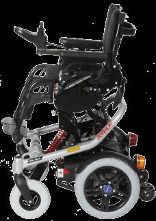
24 Product description 3 Product description The power wheelchair for children can be used indoors according to EN category A. But it also fulfills the requirements for outdoor areas with regard to the climate and splash-proof tests. The is designed to be compact and manoeuvrable indoors. The powerful drive system supplied by two 12 V batteries and the drive wheels allow obstacles to be overcome easily and provide safe driving characteristics. The power wheelchair is controlled by an enable50 wheelchair control unit. The latter includes a control panel to enter driving commands and display the current status as well as a controller that operates the drive motors and other electrical functions based on the inputs. The enable50 is programmable so that the controls can be adjusted to the individual user requirements. The speed, acceleration and delay values, for example, can be adjusted. A special control unit with alternate input modules is available (see chapter 7.2). Special features of the power wheelchair include: Compact design. Easy operation. Easy to service due to the modular design. Easy access to all modules. Individual adaptation possibilities with options and custom fabrication using modular components (chassis, seating system, control unit, accessories). The modular design allows the to be equipped with further modules and installed equipment in addition to the main components (see Fig. 1), e.g. attendant controls, electric seat options, etc. These are described in greater detail in chapter Ottobock
, Charger, Instructions for Use, Options (see Chapter 7).")
25 Delivery and preparation for use 4 Delivery and preparation for use 4.1 Delivery The options included in the scope of delivery depend on the product configuration purchased with the power wheelchair. The scope of delivery includes: Adapted power wheelchair with main components (see Fig. 1), Charger, Instructions for Use, Options (see Chapter 7). The specialist dealer delivers the power wheelchair ready for use. All settings correspond to the indications on the order form or are adjusted directly on site by the dealer. The power wheelchair is adapted to the personal requirements of the individual. The functionality of the individual components can be tested by following the instructions in chapter 6. Chapter 8 includes a description of possible malfunctions. The optional toolkit contains a set of Allen wrenches (3, 4, 5, and 6 mm) and a 13 mm open-end wrench. Fig. 1 Main components 1 Backrest 6 Motor with brake release and 2 Arm rest (side panel) drive wheel 3 Joystick and control unit 7 Anti-tipper / Frame protection rollers 4 Seat cushions 8 Locking lever 5 Footrest 9 Detachable push handle 10 Plug with battery cable Ottobock 25

. Ensure that the battery cable is seated securely in the plug (Fig. 2, item 10) or push the cable into the plug if necessary. Fig.")
26 Transportation and Storage 5 Transportation and Storage 10 Once the battery packs are removed, the can be transported as a ready-to-operate power wheelchair for children. 7 Fig. 2 Anti-tipper / plug with battery cable 4.2 Initial operation WARNING Risk of suffocation. Packaging materials must be kept out of reach of children. All components must be checked for completeness (see Figure 1) and functionality prior to initial operation. The batteries must be charged if necessary (see chapter 6.5 / 6.5.1). Ensure that the battery cable is seated securely in the plug (Fig. 2, item 10) or push the cable into the plug if necessary. Fig. 3 Backrest folded down 26 Ottobock
 are not approved for use in a vehicle for the disabled. Fig.")
27 Transportation and Storage electric seat tilt (tilt angle up to 20 ) Seat height adjustment Combined seat height adjustment / electric seat tilt Combined seat height adjustment / mechanical back angle adjustment Versions with other options (e.g. electric back angle adjustment, mechanically elevating footrest) are not approved for use in a vehicle for the disabled. Fig. 4 Removed battery packs 5.1 Transport in a Motor Vehicle for the Disabled WARNING Risk of accident and injury due to incorrect use for transportation in a vehicle for the disabled. Use in a vehicle for the disabled is only permissible if the following options are used: Standard Seat mechanical back angle adjustment mechanical seat tilt (tilt angle up to 20 ) WARNING Risk of injury due to improper transportation. The seats installed in the motor vehicle along with the corresponding vehicle restraint systems offer passengers optimum protection in the event of an accident. The power wheelchair should only be used as a seat in a vehicle for the disabled in exceptional cases, and only in conjunction with the safety elements and restraint systems offered by Ottobock. For more information, please refer to our brochure "Using your Wheelchair / Mobility Base with Seating Shell or Buggy for Transportation in Motor Vehicles for the Disabled", article number 646D158. Observe the additional limitations regarding installed options (see previous safety note). Ottobock 27

. 5.1.")
28 Transportation and Storage CAUTION Risk of injury due to insufficient restraints. During transport in another vehicle, the power wheelchair must be secured sufficiently with tensioning straps. Ensure that the wheelchair is fully secured with tensioning straps during transportation in a motor vehicle for the disabled. Four eyelets are provided on the frame of the Skippi plus in order to attach straps (Fig. 3/4). Before transporting the power wheelchair, switch the control unit off and engage the wheel lock (see chapter 6.4) Required Accessories To use the power wheelchair as a seat in a wheelchair accessible vehicle, additional accessories have to be mounted (491S00=SK024 Anchor Point Kit). The qualified personnel which fit the wheelchair can provide more information. 5.2 Disassembling the power wheelchair NOTICE Risk of cable damage. Take care to ensure that cables are not pinched when the wheelchair is disassembled/assembled. Fig. 5 Rear eyebolts, front eyebolts The frame and drive unit must not be separated if the is equipped with one of the following electric options: - Seat height adjustment - Electric seat tilt - Electric back angle adjustment In this case, skip steps no. 7/8 below. 28 Ottobock

. 4.")
29 Transportation and Storage You can reduce the transportation size of the power wheelchair in a few simple steps in order to transport it. Always put the respective parts which were removed down carefully. Please observe the following order for disassembly: 1. Remove the footrests (Fig. 6). 2. Remove the control panel from the armrest and carefully lay it down on the ground (Fig. 7). Fig. 7 Removing the control panel 3. Remove the side panels (Fig. 8). 4. Pull the release strap on the backrest and fold the backrest forward and down (Fig. 9). Fig. 6 Removing the footrest Ottobock 29

. Now the battery packs are accessible. 6.")

30 Transportation and Storage 5. Release the seat lock by pulling on the release strap and folding the locking bar back at the same time (Fig. 10). Now the battery packs are accessible. 6. Remove the battery packs (Fig. 11). Fig. 8 Removing the side panels Fig. 10 Releasing the seat lock Fig. 9 Folding the back rest down 30 Ottobock
 down 7.")
 above the antitipper rollers until these touch")

31 Transportation and Storage Fig. 11 Removing the battery packs Fig. 12 Push the step points (frame protection rollers) down 7. Separate the frame from the drive unit: Push down on the step points (frame protection rollers) above the antitipper rollers until these touch the ground (Fig. 12). 8. Now the frame can be separated from the drive unit by lifting it slightly and pulling it back (Fig. 13). Fig. 13 Lifting / removing the frame Ottobock 31

32 Transportation and Storage 9. For the "height-adjustable push handles" option, loosen the quick-release levers, then push the handles all the way down and fold them in if necessary (Fig. 14). Fig. 14 Loosen the height-adjustable push handles To reduce the required space, the two battery packs can be placed back into the drive unit. Ensure that the red arrows on the battery packs point forward. The locking lever should be engaged again to prevent the battery packs from falling out. The control panel can be laid on top of the battery packs (Fig. 12) or placed into the corresponding holder. Ensure that the control panel is not switched on and that cables are not pinched. 32 Ottobock Now the power wheelchair is ready to transport and can be stowed in a vehicle. NOTICE Risk of damage if not tied down sufficiently. Secure the disassembled parts of the power wheelchair properly so that they cannot slide. Perform the steps listed above in reverse order to reassemble the power wheelchair. Ensure that the locking bar is pushed back into its proper position (see Fig. 11a, Pos. 1) and both locking pins engage correctly (see Fig. 11a, Pos. 2). CAUTION Risk of injury if the locking mechanism is not properly engaged. Check that the locking pins are properly engaged at both sides on the outside of the base support. The bolts must be clearly visible so that the frame cannot unexpectedly disengage from the drive unit sustainer. (see Fig. 11a, Pos. 3).
.")

33 Transportation and Storage 5.3 Storage The power wheelchair must be stored in a dry place. The ambient temperature must be maintained between -10 C and +40 C during transportation and storage. Fig. 11a Fig. 11b Locking bar and locking pins, engaged Locking pin, engaged Tyres contain chemical substances that can react with other chemical substances (such as cleaning agents, acids, etc.). If your power wheelchair is not moved for several days, permanent colour changes may occur where the wheelchair comes into contact with the surface it is standing on. A suitable surface must therefore be ensured if the wheelchair is parked for extended periods of time. Direct exposure to sunlight / UV radiation causes the tyres to age more quickly. As a result, the tread surface hardens and corner pieces break out of the tread. Ottobock 33
34 Operation Avoid parking the wheelchair outdoors whenever possible. The tyres should be replaced at least every 2 years regardless of wear and tear. Remove the fuses for shipping or when the power wheelchair is not being used for an extended period of time. 6 Operation 6.1 Adjustment Options CAUTION Risk of accidents due to unsecured screw connections. When screw connection with thread locks are loosened, they must be replaced with new thread locks or secured with a medium-strength liquid thread lock substance (e.g. EuroLock A24.20). After the power wheelchair has been adjusted or readjusted, the attachment screws and/or nuts must be re-tightened firmly. Observe any torque settings which may be specified. Various adjustments can be made to the power wheelchair. The seat width as well as the seat and back position are set according to the customer order and may only be changed by a specialist dealer. The following items can be adapted by the user: Back angle Seat angle Armrest height Armrest position Lower leg length (seat depth) The footrests and side panels can be removed if necessary. The user can make all adjustment options using the optional available toolkit or by hand. The power wheelchair for children can be disassembled easily by an attendant (see chapter 5.2 Disassembling the Power Wheelchair) Backrest The backrest can be set to four different angles by pulling the release strap (bottom of the backrest, Fig. 15). 34 Ottobock

35 Operation Once the backrest is in the desired position, release the strap to let the locking mechanism engage in the next available position. Fig Seat angle Release strap for the backrest CAUTION Risk of injury due to improper adjustment work. The user must not sit in the wheelchair during seat angle adjustments. Remove the fuses for shipping or when the power wheelchair is not being used for an extended period of time. The seat angle can be changed using the seat tilt function if the power wheelchair is equipped with an electric seat tilt (see chapter 7.3.2). The power wheelchair offers three different seat angle settings (-6, +3 and +12 ). 1. Loosen the two Allen head screws located at the front below the seat (Fig. 16). 2. The desired seat angle can be set by placing the pin in the corresponding hole. 3. Tighten the Allen head screws properly again after making the adjustment. 4. Check that the retaining clip on the pin is closed every time after the seat angle is adjusted. Ottobock 35

36 Operation Fig. 16 Loosen the Allen head screws Fig. 17 Removing the side panel Side panel with armrest Removing the side panel with armrest 1. Loosen the thumb screw at the lower end of the side panel holder. 2. Pull the side panel with armrest up and out. 3. Retighten the thumb screw properly after reinstalling the side panel. If the control panel is attached to the armrest, it must be removed before taking the side panel out (chapter 6.1.4). Adapting the armrests to the upper arm length 1. Use a size 3 Allen wrench to loosen the set screws. 2. Move the side panel with armrest up or down the rail to the desired position. 3. Retighten the Allen head screw properly. 36 Ottobock


37 Operation Fig. 18 Adapting the armrest to the upper arm length Fig. 19 Adapting the armrests to the forearm length Adapting the armrests to the forearm length 1. Use a size 3 Allen wrench to loosen both set screws on the bottom of the armrest. Three set screws need to be loosened on the side where the control panel is mounted. 2. Move the armrest with the control panel holder or replacement tube forward or backwards along the attachment rail to the desired position. 3. Retighten all set screws Control Panel CAUTION Risk of accidents and injury due to uncontrolled movements of the wheelchair. Turn the power wheelchair control unit off before mounting or removing the control panel or changing its position. NOTICE Cable damage. Positioning the cable incorrectly can lead to pinching and thus damage to the cable. The cable must not be too tight or too loose. Avoid bending or crushing the cable. Ottobock 37
, the control panel is removed from the control panel bracket ball coupling (Fig. 21). Fig. 21 Removal for a swing-away control panel holder Fig.")

38 Operation Removing the Control Panel The control panel can be removed simply by pulling on it (Fig. 20). For a swing-away control panel (see chapter 7.7.1), the control panel is removed from the control panel bracket ball coupling (Fig. 21). Fig. 21 Removal for a swing-away control panel holder Fig. 20 Removing the control panel Adapting the control panel to the arm length The control panel is attached to a rail which is located beneath the armrest. 1. Use a size 3 Allen wrench to loosen all three set screws on the bottom of the armrest. 2. Move the control panel with the control panel holder or replacement tube forward or backwards along the attachment rail to the desired position. 3. Retighten all set screws. If the control panel rail is too long, the protruding part can simply be cut off. 38 Ottobock

39 Operation Footrest CAUTION Risk of pinching. Ensure that your fingers are not in the danger area when flipping the footrests up or down. The footrests may only be removed entirely from their holders when the wheelchair is being transported. Removing the footrests 1. Press the footrest latch (see Fig. 23). Fig. 22 Adapting the control panel Changing the control panel mounting side The control panel mounting side may only be changed by authorised personnel. The standard configuration has the control panel mounted on the right side. It can also be mounted on the left side of the power wheelchair if the user so desires. 2. Pull the footrest up and remove it. Installing the footrests 1. Slide the footrest into the holder from above until the latch clicks in place. Ottobock 39

. 2. Move the footrest up or down to adapt it to the individual lower leg length and seat cushion thickness. 3.")

40 Operation When adjusting the footrest height, ensure that the footrest bar is inserted into the swivel segment by at least 60 mm. After completing the adjustment, tighten the set screw with a torque of 8 Nm. Fig. 23 Footrest latch Adapting the footrests to the lower leg length 1. Use a size 4 Allen wrench to loosen the screws on the back of the footrest bar (Fig. 24, left). 2. Move the footrest up or down to adapt it to the individual lower leg length and seat cushion thickness. 3. The footrest angle can be changed when the locking lever is released (Fig. 24, right). 4. Re-tighten the screws properly. Fig. 24 Adjusting the lower leg length Moving the footrest holder The footrest holders can be moved together in the longitudinal direction (Fig. 25) and individually/independently in the lateral direction (Fig. 26). 1. Loosen the corresponding two screws on the seat frame. 2. Move the footrest holder to the desired position. 3. Re-tighten the screws properly. 40 Ottobock


41 Operation Fig. 25 Footrest holder: Adjusting the longitudinal position 6.2 Getting In and Out CAUTION Risk of injury if the power wheelchair starts rolling. The power wheelchair controls must be switched off while getting in and out. This will engage the motor brake automatically. CAUTION Risk of breakage due to overloading. The user may not support their full weight on the footrests or armrests while getting in and out. The modular design of the power wheelchair and the ease with which you can remove the side panels and footrests make it easy to get into and out of the wheelchair from the side or from the front. Users can get into and out of the wheelchair using the method best suited to each individual. Fig. 26 Footrest holder: Adjusting the lateral position From the side To get in from the side, the right or left side panel corresponding to the entry side must be removed. If possible, always get in on the side opposite the control panel. Ottobock 41


42 Operation 1. Bring the power wheelchair as close as possible to the place where the user is sitting. 2. If the control panel is on the side the user wants to use to get into/out of the wheelchair, then undo the hook and loop closures that fix the cable for the control panel to the wheelchair and remove the control panel. 3. Remove the side panel (see chapter 6.1.3). 4. Remove the footrests if necessary (see chapter 6.1.5). The user can then slide into the seat from the side. This process is easier if a transfer board is used From the front Fold both footrests up to get into and out of the chair from the front. Removing the footrests increases the available space to get in or out (Fig. 28/29). The assistance of an attendant or a transfer lifter allows the user to get into or out of the power wheelchair easily. A rotation plate may be used for support. Fig. 28 Footrests flipped up Fig. 27 Preparing to get into the chair from the side 42 Ottobock

43 Operation NOTICE Risk of damage to other devices. The power wheelchair may generate electromagnetic fields that can cause interference with other devices. Therefore, switch the controls off whenever you don't need them. Fig. 29 Footrest removed 6.3 Control unit NOTICE Risk of impairing the driving performance of the power wheelchair. The driving characteristics of the power wheelchair can be affected by electromagnetic fields (mobile phones or other radiating devices). Therefore all mobile devices must be turned off while driving Control Panel The power wheelchair is operated using the control panel. The control panel consists of a keypad, LCD display and joystick. The charging/programming receptacle and two inputs for external push-buttons are located on the underside. The power wheelchair is turned on and off using the keypad; driving commands can be entered and the status of certain functions and components can be displayed. Ottobock 43


44 Operation Horn The horn will sound as long as the horn button is being pressed. Warning flasher Pressing the warning flasher button activates or deactivates all four direction indicator lights. Fig. 30 Control panel 1 Joystick 7 Horn 2 Direction indicator, left 8 Direction indicator, right 3 Warning flasher 9 Light 4 LCD Display 10 Charging / programming receptacle 5 On/Off Button 11 Connector for external On/Off button 6 Mode button 12 Connector for external mode button Pressing the mode key briefly increases the speed level. After reaching the maximum speed level, you can change back to speed level 1 by pressing the button again ( ). Pushing and holding the button for at least 2 seconds switches the control unit to the Electric seat function menu. Light The front and rear lights are activated and deactivated by pressing the light button. Direction indicator lights The right or left front and rear direction indicator lights are activated and deactivated by pressing the respective direction indicator, right or direction indicator, left buttons. The direction indicator lights turn off automatically after 20 seconds. LCD Display The LCD display is the communication interface between the user and the control unit. It indicates the selected speed level, the remaining battery capacity and the status of electric options and special functions as well as warnings and errors. All display symbols are visible during the initialisation phase. 44 Ottobock

45 Operation Separate LCD monitor A separate LCD monitor with infrared and Bluetooth (optional) is available to operate special controls and for environment control functions. See chapter for more information Switching on and off Fig. 31 LCD display with all symbols WARNING Danger to life due to lack of brake functionality. The wheel lock release lever must be locked when using the power wheelchair. The automatic wheel lock must be operational and functional. 1 Direction indicator, left 9 Excess temperature 2 Battery capacity 10 Direction indicator, right 3 Electric backrest 11 Wheel lock for drive wheels 4 Electric seat tilt 12 Warning 5 Control Panel 13 Creep speed 6 Drive-away lock 14 Power module 7 Speed level 15 Drive motor 8 Open-end wrench 16 Light CAUTION Risk of accidents due to incorrect tyre pressure. The power wheelchair must be visually inspected prior to each use to ensure that the tread depth is sufficient and that the tyres are inflated to the correct pressure. Incorrect tyre pressure reduces the life of the tyres and impairs the driving characteristics. The power wheelchair controls are turned on or off by pressing the On/Off key (see Fig. 30, item 6). The wheelchair turns off automatically if the control panel is not used for an Ottobock 45
46 Operation extended period of time. It is also possible to switch the power wheelchair off with the On/Off button while driving. In this case, the wheelchair brakes immediately until it comes to a stop. The specialist dealer can use the parameter settings to establish the user's desired default speed level or menu for the power wheelchair after it is turned on Driving function WARNING Risk of accidents when driving without experience. In order to avoid dangerous situations and falls, user and attendant must first become familiar with the power wheelchair for children on level ground. CAUTION Risk of injury due to uncontrolled operation of the power wheelchair. The power wheelchair controls should be switched off whenever the driving function is not required. This will prevent unintentional activation of the joystick. CAUTION Risk of injury due to tipping during operation. The following safety measures must be observed when operating the power wheelchair: Operation is limited to inclines up to a maximum of 12 %. When driving downhill, reduce speed according to the steepness of the incline. Do not cross obstacles with a difference in height > 5 cm. Do not cross steps or curbs without reducing speed. The specialist dealer can use the parameter settings to establish the user's desired default speed level or menu for the power wheelchair after it is turned on. The control unit of the power wheelchair switches to a safe mode at elevated temperatures and after driving uphill for extended periods of time, limiting the performance of the power wheelchair. However, the user/attendant is able to drive the power wheelchair out of a hazardous situation at any time. The power wheelchair is fully functional again once the unit has cooled down sufficiently (this may take several minutes depending on the ambient temperature). 46 Ottobock
47 Operation The power wheelchair has been approved for ascending or descending inclines of up to a maximum of 12 %. Driving on steeper inclines or downgrades is not permitted. In order to navigate downgrades safely, the speed must be reduced according to the slope (e.g. select speed level 1). The critical obstacle height of the power wheelchair is 5 cm. Crossing obstacles which exceed 5 cm in height is not permitted. Obstacles such as steps or curbs must be crossed at reduced speeds. If obstacles are in the way, drive around them with a wide margin. Uncontrolled driving behaviour may occur on uneven ground. Therefore the speed must always be adjusted to the ground conditions. The battery indicator and speed level are shown in the driving menu on the LCD display. The joystick (see Fig. 30, item 1) is used for driving. The further the joystick is moved away from the centre position, the faster the power wheelchair will drive in this direction. The maximum speed at full deflection of the joystick depends on the selected speed level. Releasing the joystick automatically activates the brake function, bringing the wheelchair to a halt. The mechanical wheel locks are activated automatically when the power wheelchair comes to a standstill so that it cannot roll. The power wheelchair has a programmable number of speed levels (delivery condition = 5 speed levels). Use the M button to increase the speed level. After reaching the maximum speed level, the control unit switches back to speed level 1. Adjusting the driving characteristics WARNING Risk of accidents and injury due to incorrect configuration settings. Modified parameter settings in the configuration can lead to changes in driving characteristics. In particular, changes to the speed, acceleration, braking or joystick settings can lead to unexpected and therefore uncontrollable operating performance with a risk of accidents. Always test the driving characteristics of the power wheelchair after configuration / programming is complete. Programming may only be performed by authorised, trained specialists. Ottobock and the control unit manufacturer are not liable in cases of damage caused by programming which was not performed correctly and/or which was not adjusted correctly according to the abilities of the wheelchair user. Ottobock 47
48 Operation Only authorised specialist dealer service personnel can use a handheld programming device, which is connected to the control panel, to adapt the speed, acceleration and deceleration values to the individual wishes of the user Battery Capacity indicator Immediately after switching the power wheelchair on, the battery indicator shows the battery capacity that was saved before the wheelchair was last switched off. The exact battery status is displayed after driving a short distance. The battery indicator on the LCD monitor is divided into 7 segments that show the current battery capacity. A charge of 100% corresponds to 7 segments on the battery symbol. As the remaining battery capacity decreases, the LCD segments turn off one by one (see Table 1). When the last segment flashes, the battery must be charged immediately. If all the segments have disappeared and the battery symbol is flashing, the battery is under voltage. Since any further use will lead to battery damage, a warning signal also appears. If all segments of the battery symbol are flashing, this means that the battery is over voltage. Since this will lead to battery damage, a warning symbol also appears. The charging process is indicated by the battery segments lighting up one after the other. The driving function is locked out while the battery is charging. Display symbol Information Driving menu with speed level and battery capacity Low battery capacity Charging process with drive-away lock Battery is under voltage, with warning symbol 48 Ottobock
49 Operation Tab. 1 Battery indicator on the control panel Battery is over voltage, with warning symbol Controlling additional electrical functions For more information on the additional electrical functions, please see chapter 7. Additional electrical functions, e.g. electric back angle adjustment or seat tilt, are accessed by pressing the M button (approximately 2 seconds). To switch between the different functions, press the "M" button briefly or move the joystick to the right. The currently selected function is shown on the LCD monitor. The respective function can be extended or retracted by moving the joystick forward or back. The electric motor moves the respective function as long as the joystick is deflected and stops at the end positions. Electric back angle adjustment: The backrest is moved forward or back electrically when the joystick is deflected to the front or back. The electric motor moves the backrest as long as the joystick is deflected and stops at the end positions. Electric seat tilt: The seat is tipped back electrically when the joystick is deflected to the back. Deflecting the joystick to the front tilts the seat forward until it is level (factory setting, may be adapted by the specialist dealer). Seat height adjustment function: Deflecting the joystick to the front or back raises or lowers the seat electrically. The speed is reduced (creep speed) as soon as the seat height adjustment fixture leaves the lowest position, because the power wheelchair is less stable. This is indicated on the control panel by the snail symbol on the LCD monitor (see Fig. 30, item 13). Coupled seat adjustment: When the joystick is deflected to the front or back, the backrest and seat are moved electrically at the same time, forward and down or back and up. Pressing the M button (approximately 2 seconds) switches back to driving mode. Ottobock 49
50 Operation Tab. 2 Display symbol Information Electric back angle adjustment Electric seat tilt Electric seat height adjustment Coupled electric seat adjustment (backrest and seat tilt) Creep speed Display of electric seat functions on the control panel Drive-away lock The drive-away lock can be activated in the manner described below if the Drive-away lock parameter is set to On. The drive-away lock parameter is set to "Off" by default. The factory setting may also have been set to On by the specialist dealer or at the factory according to the order. Please ask your specialist dealer about the setting selected for your wheelchair. The power wheelchair control unit features an electronic drive-away lock. This function is activated/deactivated with the control panel. Activation via control panel 1. While the control unit is turned on, press and hold the mode button for at least 5 seconds. 2. A short beep confirms that the drive-away lock was activated (if keypress beeps are activated, then the drive-away lock is only active after the second beep). 3. The control unit is turned off automatically. 4. Activation of the drive-away lock is indicated by the key symbol on the display. 50 Ottobock

51 Operation Tab. 3 Display symbol Information Drive-away lock Display of the drive-away lock on the control panel Activation via separate LCD monitor If a special control is used, then the drive-away lock is activated via the separate LCD display. Select the menu item "Drive-away lock" in the "Settings" menu. Activation is confirmed with an acoustic signal and the control unit is switched off. Deactivation via control panel 1. Press the On/Off button to turn the control unit on. 2. Push the joystick as far forward as possible until a beep sounds. 3. Push the joystick as far back as possible until a beep sounds. 4. Release the joystick. Another beep confirms deactivation of the drive-away lock. 5. The speed level and battery indicator are displayed. The drive-away lock is deactivated and driving is enabled. The drive-away lock remains activated if the joystick is not moved correctly. In order to deactivate the drive-away lock, the control unit must be switched off again. The power wheelchair can be switched on again and the drive-away lock can be deactivated. Fig. 32 Drive-away lock display Deactivation via separate LCD monitor An information screen is shown on the LCD monitor after the power wheelchair is switched on. The deactivation process is the same as described under Deactivation via control panel. Ottobock 51
52 Operation Steering Lock The steering lock can be activated in the manner described below if the Steering Lock parameter is set to On. The steering lock parameter is set to Off by default. The factory setting may also have been set to On by the specialist dealer or at the factory according to the order. Please ask your specialist dealer about the setting selected for your wheelchair. The enable50 control unit in the power wheelchair may be programmed with the optional Steering Lock parameter. If the steering lock is activated, the caster wheels or the drive wheels (depending on the type) are set straight ahead. This makes it easier to negotiate narrow ramps and to use elevators. When the joystick is deflected forward, the power wheelchair drives straight ahead. When the joystick is deflected backward, the power wheelchair drives straight back. Turning is not possible when the steering lock is activated. The warning flasher lights flash when the steering lock is activated (standard programming). 52 Ottobock Activating the Steering Lock 1. Bring the power wheelchair to a full stop. 2. Push the [Warning Flasher] button.the steering lock is activated. All warning flasher lights flash (standard programming). 3. Move the joystick forward/backward. The power wheelchair only drives straight ahead or back. Deactivating the Steering Lock 1. Bring the power wheelchair to a full stop. 2. Push the [Warning Flasher] button. The steering lock is deactivated. All warning flasher lights stop flashing. 3. Move the joystick. The power wheelchair now drives in the chosen direction without steering lock. 6.4 Releasing and engaging the wheel lock WARNING Danger to life due to wheel lock malfunction. Incorrect wheel lock settings can lead to a loss of brake functionality and therefore to serious bodily injuries and even death. Repairs and adjustments to the wheel lock may only be carried out by authorised service personnel.
. When moving the power wheelchair on an incline, the person pushing must provide the appropriate brake force.")
53 Operation WARNING Risk of accidents and injury due to lack of brake functionality. No brake functionality is available when the wheel lock is deactivated (push mode). No brake functionality is available when the brake is unlocked (push mode). When moving the power wheelchair on an incline, the person pushing must provide the appropriate brake force. The brake function may only be released in the presence of an attendant. Should the user be unable to release the brake himself, the brake can be released by the attendant. NOTICE Risk of damage when parking without engaging the wheel lock. Deactivating the wheel lock may result in uncontrolled rolling of the power wheelchair. Therefore, make sure that the wheel lock is engaged when parking the power wheelchair. In case of control unit failure or insufficient battery capacity, the power wheelchair can be pushed. To do so, the wheel lock is deactivated via the mechanical release. The wheel lock releases are located on the right and left of the driving motors. Releasing the wheel lock To release the wheel lock, first pull the red safety pin on both sides. Then the red wheel lock release lever can be swung out. The safety pin prevents unintended activation of the wheel lock release. Fig. 33 Engaging/disengaging the wheel lock 1 Safety pin 2 Wheel lock release lever In this position, the control unit will recognise that the wheel lock has been disengaged and will automatically deactivate the driving function. A warning will appear on the LCD display as soon as the joystick is deflected: Ottobock 53
54 Operation Display symbol Information Wheel lock is disengaged The control unit activates the driving function again when both wheel lock release levers are engaged. 6.5 Batteries Tab. 4 Control panel display when the wheel lock is disengaged If the control unit does not indicate an error on the control panel when the wheel lock lever is disengaged, this indicates a malfunction which must be corrected by the specialist dealer promptly. All braking systems are deactivated once the wheel lock release lever has been disengaged. The control unit may be switched off in push mode. Engaging/activating the wheel lock To engage the wheel lock, push the red wheel lock release lever (Fig. 33) back until the safety pin clicks into place. NOTICE Risk of damage to the battery packs. The batteries are encapsulated in battery packs at the factory. The battery packs may not be opened, since this could cause irreversible damage to the encapsulated batteries or the battery pack. Checking the remaining battery capacity and charging the battery in time are essential in order to ensure the operational safety of your power wheelchair. Before doing any maintenance work on the batteries, please read the battery manufacturer's warnings thoroughly. Observe the disposal information (see chapter 11). The power wheelchair is equipped with two maintenance-free 31 Ah (C20) / 27 Ah (C5) / 12 V-GEL bat- 54 Ottobock

55 Operation teries at the factory. The batteries are located in 2 battery packs below the seat of the power wheelchair (Fig. 34). To display the battery capacity on the control panel, see chapter Fig. 34 Battery pack Due to the sealed design, the GEL technology used fulfills the latest safety and environmental compatibility provisions. The battery packs are integrated in separate battery packs for additional safety and improved handling. The batteries were designed for high cycle stability and are particularly well suited to traction operation due to the special lead plates. Please contact your authorised specialist dealer to replace or dispose of the batteries (batteries in the battery pack). The batteries must be replaced as complete units (battery packs). Proceed as follows to remove/install the battery packs: 1. Release the seat lock by pulling on the release strap and folding the locking bar back at the same time (Fig. 10). 2. The battery packs are now accessible Remove the battery packs (Fig. 11). 3. Place the new battery packs back into the drive unit. Ensure that the red arrows on the battery packs point in the driving direction and that the plug contacts (Fig. 35) engage with the battery contacts. 4. The locking lever should be engaged again to prevent the battery packs from falling out (Fig. 10). Ottobock 55

56 Operation Fig Charging Bottom of the battery pack WARNING Risk of injury due to explosive gases. Explosive gases can form while the batteries are charging. The following safety instructions must be observed under all circumstances: Ensure sufficient ventilation in enclosed spaces. Don't smoke or light fires. Ensure that no sparks are generated. NOTICE Risk of battery damage. Driving for longer periods with only the lower segments of the battery indicator lit will result in deep discharge and damage to the battery. There is a risk that the power wheelchair may stop due to zero battery capacity and place the user in a dangerous situation. The range of the power wheelchair is determined by the battery capacity. The battery capacity is influenced by many factors. In addition to the temperature, age of the batteries, and speed, the charging cycle also has a pronounced effect on the capacity and therefore on the range. The following applies for an optimal charging frequency: The batteries can be charged at any time, regardless of the remaining battery capacity. It takes about 16 hours until a discharged battery (only one flashing segment) is completely charged. When the charging process is complete, the battery charger can remain connected to the power wheelchair with no risk of overcharging or damaging the battery. The battery charger features a programmed recharging phase that will maintain the battery capacity at the level that has been reached. 56 Ottobock
57 Operation For daily use, connecting the charger overnight is recommended so that the full capacity is available every day. The batteries will gradually discharge if the wheelchair is not used for extended periods of time. If the power wheelchair is not driven for extended periods of time, a charging cycle must be carried out at least once per week in order to maintain the battery capacity. Removing the fuse if the wheelchair is not used for extended periods of time is recommended. The batteries should never be fully discharged (deep discharge). The power wheelchair control unit must be switched off while the batteries are charging to allow all of the charging current to be fed into the battery. The following must be observed when charging the batteries: Only the battery charger provided by Ottobock may be used for charging. Failure to comply will void the warranty. The voltage settings on the battery charger must correspond to the mains voltage used in your country Charger WARNING Explosion hazard due to sparks. The battery charger must always be switched off and the mains plug removed before disconnecting the battery. NOTICE Unauthorised battery replacement. Batteries may only be replaced by a specialist dealer. The characteristic charging curve programmed in the charger at the factory matches the supplied battery and may not be changed independently. Setting the characteristic curve incorrectly can result in permanent damage to the battery. The battery charger is designed for gel batteries (maintenance-free batteries). The charger is programmed with the matching characteristic curve for ideal charging of the respective battery type. The matching characteristic curve is set at the factory when the power wheelchair is shipped. The characteristic curve has to be checked if the battery charger is to be used with another power wheelchair or if new batteries are installed. Ottobock 57
58 Accessories NOTICE Risk of battery damage. Setting the characteristic curve incorrectly can result in permanent damage to the battery. The following safety instructions must be observed when handling the battery charger: Always place the rubber feet of the charger on a level surface. Protect the charger from direct sunlight to avoid additional heating of the device. The charger must be located in a dry and well ventilated location. Avoid letting dust and dirt enter the battery charger. This can impair the battery charger functionality. Use a dry cloth to clean the battery charger Charging Process To charge the batteries, proceed as follows: 1. Turn the control unit on the power wheelchair off. 2. Plug the charger into the charging receptacle on the power wheelchair control panel (see Fig. 30, item 10). 3. Connect the battery charger to a wall outlet. The batteries will start charging automatically, and the current 58 Ottobock charge status is indicated on the LEDs of the battery charger (see Tab. 5). 4. After completion of the charging process: Disconnect the mains plug and the charger plug on the control panel. 5. Turn on the control unit; the power wheelchair is now ready to use. Please see the instructions for use supplied with the battery charger for further details on use and on the LED indicators. 7 Accessories CAUTION Risk of accidents due to unsecured screw connections. When screw connection with thread locks are loosened, they must be replaced with new thread locks or secured with a medium-strength liquid thread lock substance (e.g. EuroLock A24.20). After the power wheelchair has been adjusted or readjusted, the attachment screws and/or nuts must be firmly retightened. Observe any torque settings which may be specified.

59 Accessories Only original accessories provided by the manufacturer may be used. The optional components may only be mounted as described here. All available optional add-on components are contained on the order form and in the accessories catalogue. The power wheelchair has been designed as a modular system. Certain modules can be exchanged and other accessories can be added. The control unit allows for the addition of numerous additional electrical functions and specially adapted input devices. The complete range of options is listed on the order form and in the wheelchair accessories catalogue. Some important options are described in more detail below. 7.1 Attendant control A separate control panel can be used on the wheelchair for operation by the attendant. It is installed on the push handle and is height adjustable / removable. Fig. 36 Attendant control Functional overview The attendant control can be used to operate the driving function and the electric seat functions. The module can be connected to the control unit in combination with the hand control device or separately. Ottobock 59
60 Accessories The control panel displays the following after the attendant control is turned on: Display symbol Information Attendant control activated Tab. 5 "Attendant control activated" display Fig. 37 Attendant control overview Battery LED (item 2) The battery LED lights up when the unit is on. Colour and flash codes provide information on the current battery capacity status: 1 On / Off button 5 Display of the selected electric 2 Battery LED seat function 3 Mode button 6 Joystick 4 Mode LED On/Off button (item 1) The button is used to turn the power wheelchair on, to activate the drive-away lock (also see chapter 6.3.7), and to turn the wheelchair off. 60 Ottobock LED Status Green is lit Battery capacity > 70% Orange is lit Battery capacity 30%-70% Red is lit Battery capacity < 30% Red is flashing Battery deep discharge - charge immediately Battery over-voltage (e.g. Green is flashing after driving downhill) - Continue driving slowly
61 Accessories Red/Orange/Green flashing alternately Tab. 6 Battery Capacity indicator Charging process / drive away lock Mode button (item 3) Switch between speed level 1 and 2 by pressing the button briefly. Push and hold the button (at least 2 seconds) to switch the control unit to the electric seat functions. Mode LED (item 4) The Mode LED indicates the speed level status and system faults using 3 colour LEDs and various flash codes: LED Status Green is lit Speed level 1 Orange is lit Speed level 2 Red flashing 1x/2x/3x/4x/5x Fault (see chapter 8.2.2) Off LED display switched to seat functions Tab.7 Display of the speed levels / system faults Display of the selected electric seat function (item 5) The electric seat functions are accessed by pressing and holding the "M" button (approx. 2 seconds). The currently selected seat function is indicated on the control panel display (see chapter 6.3.6) and by the following LEDs on the attendant control: LED indicator Tab. 8 Information Display of electric seat functions Electric back angle adjustment Electric seat tilt Electric seat height adjustment Coupled electric seat adjustment (backrest and seat tilt) Ottobock 61
62 Accessories Moving the joystick right switches between the different seat functions. The selected function can be extended or retracted by moving the joystick forward or backward (also see chapter 6.3.6). The corresponding LED flashes if an error occurs. See chapter for the meaning of the fault notifications. Joystick (item 6) The joystick is used for driving. The further it is moved away from the centre position, the faster the power wheelchair will drive in this direction. If the seat functions are accessed with the Mode button, then the joystick is used to select and activate the seat functions (see item 5 and chapter 6.3.6). 7.2 Special controls The power wheelchair can be equipped with special controls with various input modules, e.g. with: Mini/Midi joystick control Chin control Buddy and Piko buttons (also see chapter 7.6). Detailed information on the respective controls can be found in the respective included instructions for use "Special Controls" (serial number: 647G636). Note that the cannot be equipped with a foot control. 7.3 Electric seat options WARNING Risk of crushing or pinching in the power seat adjustment and lifting areas. When the seat height, back angle, or the seat tilt are adjusted, areas which can cause pinching or crushing injuries are found between the seat and wheelchair frames. This must be explained to all attendants. In order to prevent injuries, ensure that body parts such as hands and feet are always kept out of the danger zone, that no interfering objects such as clothing or obstacles are in the danger zone and that no unauthorised persons are present. 62 Ottobock
63 Accessories CAUTION Risk of injury if the power wheelchair tips over. The seat tilt must be in the home position, the fixture to adjust the seat height must be in the lowest position and the back rest must be upright before negotiating uphill slopes and driving up low curbs. When negotiating downhill slopes or driving down low curbs, moving the seat tilt back slightly and approaching at low speed (max. 3 km/h) is recommended. CAUTION Risk of injury due to improper use of the seat adjustment. Overloading the seat height adjustment actuators may cause the spindle nut to break, causing the seat to sag or the backrest to flip back. The guidelines provided below for actuator activation times must be observed. NOTICE Damage due to improper use of the electric seat adjustment. The power wheelchair can be equipped with seat height, back angle, and/or seat tilt adjustment features. The following particularities must be observed during operation: The seat function actuators are not intended for continuous use, only for short-term operation under limited loads (10 % use, 90 % idle time). As a guideline, 10 seconds of activation time under maximum load should be followed by approx. 90 seconds of idle time. The electric seat functions are considered independent of the driving function for this purpose. Overloading the actuators may cause the spindle nut to break, causing the seat to sag or the backrest to flip back. Observe the activation time guidelines specified above. The electric seat function may not be activated in case of faults or malfunction. Bring the seat to a level position when getting into or out of the power wheelchair. For safe operation, please also observe the information in chapter 2.3 General Safety Instructions and chapter 2.5 Safety Requirements for Operation. Ottobock 63
64 Accessories Seat height adjustment For safe operation, observe the information at the beginning of chapter 7.3. The seat height adjustment can be combined with the electric seat tilt function. It allows the seat to be tilted by up to 20. WARNING Risk of injury if the power wheelchair tips over. Creep speed is automatically activated when the seat height adjustment function is used. If this is not the case, there is a malfunction and the seat height adjustment function must not be used. Contact a specialist dealer as soon as possible to eliminate the problem. CAUTION Risk of injury if the power wheelchair tips over. When the seat is raised, the power wheelchair may tip over and the user may fall out. Therefore the following safety instructions must be followed under all circumstances: When the seat is raised, only cover short distances, e.g. in order to manoeuvre. 64 Ottobock The seat height adjustment function may only be used with the backrest in the upright position. Fasten the lap belt if possible. Only use the seat height adjustment function on level ground. Do not modify the installation position of the seat height adjustment fixture. CAUTION Risk of falling. The user may not lean the upper body out past the seat surface while the seat is raised. CAUTION Risk of accidents due to a restricted field of vision. Special care is required of the user when driving with a raised seat and when activating the seat height adjustment since the field of vision is limited. NOTICE Risk of damage due to improper maintenance. Inspect the seat height adjustment fixture for visible signs of damage at least once a month and ensure all screw connections are tight. Also maintain correct air pressure in the tyres.

65 Accessories NOTICE Risk of transportation damage. Always lower the seat height adjustment fixture fully for loading or transportation. A sufficient supply of power must be maintained in order to guarantee proper operation of the seat height adjustment function. The power wheelchair can be equipped with an optional seat height adjustment feature. The seat height adjustment function increases the height of the seat above the drive unit by up to 20 cm. The driving function remains available even when the seat is raised. The speed is reduced (creep speed) as soon as the seat leaves the lowest position, because the power wheelchair is less resistant to tipping. This is indicated by a snail symbol on the control panel or the optional, separate LCD display. The function is activated with the joystick in Additional functions / Seat functions mode (see chapter and 7.1.1) or via the keypad (see chapter 7.5). Fig. 38 Seat with activated seat height adjustment function Ottobock 65


66 Accessories to 25 (20 when combined with seat height adjustment) from the horizontal, e.g. for pressure relief. The seat can be tilted back continuously. A centre of gravity adjustment integrated in the power wheelchair improves stability. The function is activated with the joystick in Additional functions / Seat functions mode (see chapter and 7.1.1) or via the keypad (see chapter 7.5). Fig. 39 Creep speed Control panel display / LCD display Electric seat tilt For safe operation, observe the information at the beginning of chapter 7.3. The power wheelchair can be equipped with an optional electric seat tilt function. It allows the seat to be tilted by up Fig. 40 Electric seat tilt 66 Ottobock
. In the sitting position, the backrest can be tilted back continuously by up to 25. The function is activated with the joystick in Additional functions / Seat functions mode (see chapter 6.3.6 and 7.")
67 Accessories Electric back angle adjustment For safe operation, observe the information at the beginning of chapter 7.3. The backrest can be equipped with an optional electric back angle adjustment feature (see Fig. 35). In the sitting position, the backrest can be tilted back continuously by up to 25. The function is activated with the joystick in Additional functions / Seat functions mode (see chapter and 7.1.1) or via the keypad (see chapter 7.5). 7.4 Mechanically elevating footrests On power wheelchairs with gas compression springs, it is necessary to check for leaking oil around the piston rod. Leaks reduce the functional capabilities of the gas compression springs and may cause them to fail. Defective gas compression springs (e.g. scratches or damage to the piston rod caused by impact; deformation of the cylinder tube) must be replaced immediately. Piston rods do not require lubrication. They are maintenance-free. The power wheelchair can be equipped with mechanically elevating footrests. Proceed as follows to elevate the footrests: 1. Release the clamping lever (see arrow). 2. Select the desired position using the hole positions. 3. Engage the clamping lever. Fig. 41 Electric back angle adjustment Ottobock 67
. Examples include: Fig. 42 Elevating footrest 7.5 Push-button module CAUTION Risk of accidents due to uncontrolled driving behaviour.")
68 Accessories Available functions Depending on the power wheelchair model and the programming of the push button module, up to 5 electrical functions can be controlled during normal driving operation (Fig. 43, item 1). Examples include: Fig. 42 Elevating footrest 7.5 Push-button module CAUTION Risk of accidents due to uncontrolled driving behaviour. The push button module is an option when using the enable50 system. Improper adaptation of the push-button module to a power wheelchair which has components not included in the Ottobock modular system or modifications made later on by the user are not permissible. The push button module lets the user select additional electrical functions directly during normal driving operation. Seat tilt Electric back angle adjustment Seat elevation The symbols used on the push-button module match the symbols on the LCD display (see chapter Separate LCD Monitor with Infrared). Push button functions The M button (= mode, Fig. 43, item 2) is used to scroll through the individual functions ( ). The blue LED (Fig. 43, item 3) indicates the selected function. The selected function is activated with the arrow keys (Fig. 43, item 4) (function up / down). 68 Ottobock
.")
69 Accessories The function of the arrow keys can be adapted according to the wishes of the user (up arrow = function up or function down depending on programming). Programming may only be completed by trained specialists. Three additional Buddy buttons which can be placed freely may also be connected to the push button module as options (Fig. 43, item 5). They assume the function of the mode and up / down arrow keys (Fig. 43, items 2/4). Symbols on the back of the push button module indicate the corresponding functions Fig. 43 Push button module 1 Available electrical functions 5 Up / Down arrow keys (see 2 Function select mode button information box) 3 Selected function LED indicator 4 Mode LED 6 Stereo plug to connect Buddy buttons Ottobock 69
70 Accessories 7.6 2x adapter cable for Piko or Buddy button The power wheelchair may be equipped with a 2x adapter cable. The respective connected Piko or Buddy button may be used to control electrical seat functions. The functions to be controlled are specified when the power wheelchair is ordered. The switches are equipped with a so-called toggle function. This means that the selected function is activated as long as the button is pressed. Pressing the button again activates the selected function in the opposite direction. For example, if the electric backrest function is activated, the backrest moves back as long as the button is pushed the first time the button is activated. Activating this function again causes the backrest to move forward as long as the button is pushed. 7.7 Other Display and Control Elements Separate LCD monitor with infrared CAUTION Risk of injury due to faulty installation of third-party options. Ottobock includes an interface for alternate input devices (environment and special controls) with the LCD monitor). Ottobock does not assume any liability for combinations involving third-party special controls. The separate LCD monitor with infrared allows all types of infrared devices to be controlled using the joystick. Standard household and HiFi devices can be programmed in the control unit using a learning mode. Switches or dimmer switches are available as accessories. The mouse emulator is another available infrared module. It allows joystick signals to be used in order to control a computer mouse. The input devices of the special controls (e. g. sip-and-puff control, chin control) can also be used for infrared functions. Detailed information is contained in the Special Controls instructions for use, article number 647G636=*. 70 Ottobock
 Driving menu with speed level and battery capacity, left direction indicator activated Electric")
71 Accessories Charging process with drive-away lock Creep speed Fig. 44 Display LCD module with infrared Function Electric seat height adjustment (optional) Driving menu with speed level and battery capacity, left direction indicator activated Electric back adjustment (optional) Driving menu with speed level and low battery capacity Electric seat tilt (optional) Ottobock 71

72 Accessories Special functions, e.g. coupled electric seat adjustment (back adjustment and seat tilt) 3. The pivot element locks in place again when the holder is rotated back to the original position. Drive-away lock Tab. 9 Information displayed on the LCD monitor 7.8 Control panel holder Swing-away control panel holder with removable control panel The removable control panel can be pulled up and removed from the control panel holder. To allow the user to drive the power wheelchair closer to an object or under the edge of a table, the control panel can be folded aside with a special control panel holder: 1. Apply slight sideways pressure to the control panel holder to release the pivot element. 2. Fold the control panel holder aside. 72 Ottobock Fig Lap belt Control panel holder, swing-away WARNING Risk of injury due to improper use of the lap belt. The lap belt helps to stabilise the user sitting in the power wheelchair. Under no circumstances may the lap belt be used as part of a restraint system for transportation in a motor vehicle for the disabled.


73 Accessories The power wheelchair can be retrofit with a lap belt. This may only be used as a safety belt while driving the power wheelchair. Applying the lap belt 1. Push the two halves of the buckle together so they engage. The belt buckle must snap in place with an audible click. 2. Pull on the belt to ensure that it is locked. The lap belt should not be too tight on the body. Objects caught under the belt can cause painful pressure sores. Fig. 46 Applying the lap belt 1 Releasing the lap belt 1. Press the red release button. The buckle opens. Adjusting the Belt Length The belt length can be adjusted on both sides. 1. Position both buckle halves in the middle of the body. 2. After positioning the buckle halves at a right angle in relation to the belt, their position can be varied. The excess belt length is taken up by the plastic sliders Additional options Joystick accessories (e.g. Tetra fork; STICK S80; Softball; Golfball) Headrest mounting kit (e.g. NUTEC; Mygo; Squiggles): For mounting to the back tube Control panel guard: Metal guard for impact protection Bumper bar Manual horn Pennant Tray Tray centre control unit (only as custom fabrication) Ottobock 73
74 Malfunctions / troubleshooting Lighting Puncture-proof tyres: Solid rubber tyres These and other optional add-on components are included on the order form and in the wheelchair accessories catalogue. 8 Malfunctions / troubleshooting CAUTION Risk of accidents and injury due to uncontrolled movements of the power wheelchair. Uncontrolled movements can occur during the operation of the power wheelchair as a result of malfunctions. In this case, please contact your authorised specialist dealer immediately. During use of the power wheelchair, electrical discharges (high voltage with low current; discharge via the user) may occur which are caused by factors such as friction. However, these do not represent a health hazard. The resulting discomfort can be prevented by customisation measures (attaching a mechanical discharge contact / grounding strap to the wheelchair frame). The user s environment must be taken into consideration. Electrostatic discharge may also occur if the power wheelchair is equipped with puncture-proof tyres. Retrofitting the wheelchair with pneumatic tyres can correct this problem. Should you encounter problems while troubleshooting or if you cannot eliminate the faults completely through the measures described here, please contact your specialist dealer. Faults are indicated on the control panel LCD display or by the attendant control LEDs. Tab. 11/12 describes the individual displays with the corresponding fault sources as well as the possible causes and measures to be taken. If faults which arise cannot be fully corrected through the described measures, a specialist dealer will be able to read the exact error code with a handheld programming device and perform a targeted system analysis. All faults that have ever occurred are saved in a list and can be retrieved, e.g. in case of a general overhaul of the power wheelchair. The saved data can be used to determine future service and maintenance intervals, for example. 74 Ottobock
75 Malfunctions / troubleshooting 8.1 Warning A warning indicates a status or malfunction of one or several components of the power wheelchair. The function of components that have no errors is not restricted. For example, if the connection between the controller and seat motor malfunctions, this error will only be indicated if the user attempts to activate the motor. However, the driving function is still available. 8.2 Fault CAUTION Risk of accidents due to uncontrolled driving behaviour. Uncontrolled movements can occur during operation of the power wheelchair as a result of malfunctions. Please contact your authorised specialist dealer immediately if this occurs. A fault impairs one or several functions of the power wheelchair. The system is not fully operational until the fault has been corrected. CAUTION Risk of injury if the power wheelchair stops abruptly. In case of communication problems in the control unit bus system, the system triggers an emergency stop in order to prevent any uncontrolled functions. Depending on the source of the malfunction, it may be possible to drive the wheelchair out of a danger zone such as road traffic after switching the control unit on again. If the driving function is still not available after switching the control unit on again, the wheel lock can be deactivated (see Section 6.4) to switch over to pushing mode. Contact a specialist dealer immediately after an emergency stop! Ottobock 75
76 Malfunctions / troubleshooting Fault indication: Control panel / LCD display Display symbol LCD monitor display Warning/Fault Cause Possible corrective action Controller temperature warning Overheating due to excessive load Cool down phase Motor temperature warning Joystick warning Joystick is not in the home position when the unit is turned on Move the joystick to the home position before turning the unit on Hand control device fault Defective joystick Contact specialist dealer 76 Ottobock
77 Malfunctions / troubleshooting Display symbol LCD monitor display Warning/Fault Cause Possible corrective action Controller fault Defective controller Contact specialist dealer Communication error (alternating flashing signal) Faulty connection between the hand control device and controller; Defective cabling, software or hardware Check cabling / plug connections; Contact specialist dealer Battery under voltage Battery deep discharge Charge as soon as possible Battery over voltage Voltage too high (after full charge and driving downhill) Continue driving slowly Ottobock 77
78 Malfunctions / troubleshooting Display symbol LCD monitor display Warning/Fault Cause Possible corrective action Back angle adjustment motor fault Seat tilt motor fault Seat height adjustment motor fault Faulty cabling or plug contacts; Defective actuator Check cabling / plug connections; Contact specialist dealer Drive motor fault 78 Ottobock
79 Malfunctions / troubleshooting Display symbol LCD monitor display Warning/Fault Cause Possible corrective action Wheel lock fault Wheel lock disengaged Defective wheel lock Engage wheel lock Check wheel lock (e.g. Bowden cable) Emergency stop Severe fault caused by controller, hand control device and / or drive motor malfunction Contact specialist dealer Tab. 10 Fault notifications on the control panel / LCD display Ottobock 79
80 Malfunctions / troubleshooting Fault indication: Attendant control LED indicator Warning/Fault Cause Possible corrective action Red is flashing Battery under voltage Battery deep discharge Charge as soon as possible Green is flashing Battery over voltage Mode LED (see Fig. 37, item 4) Voltage too high (after full charge and driving downhill) Continue driving slowly Red is flashing 1 x Controller fault Defective controller Contact specialist dealer Red is flashing 2 x Hand control device fault Defective joystick Contact specialist dealer Red is flashing 3 x Communication error Faulty connection between the hand control device and controller; Defective cabling, software or hardware Check cabling / plug connection; Contact specialist dealer Red is flashing 4 x Joystick warning Joystick is not in the home position when the unit is turned on Move the joystick to the home position before turning the unit on 80 Ottobock
81 Malfunctions / troubleshooting Red is flashing 5 x Wheel lock fault Wheel lock disengaged Defective wheel lock Engage wheel lock Check wheel lock (e.g. Bowden cable) Drive motor fault Faulty cabling or plug connection; defective actuator Check cabling / plug connection; Contact specialist dealer Seat function LEDs (see Fig. 37, item 5) Backrest LED is flashing Seat LED is flashing 2 LEDs below seat are flashing Backrest / seat LED is flashing Back angle adjustment motor fault Seat tilt motor fault Seat height adjustment motor fault Electric seat function temperature warning Faulty cabling or plug contacts; Defective actuator Overheating due to excessive load Check cabling / plug connection; Contact specialist dealer Cool down phase Tab. 11 Attendant control fault notifications Ottobock 81
82 Maintenance and Care 8.3 Defect / failure A defect is the serious failure of a system component. A failure is the most serious type of malfunction and causes an immediate emergency stop of the system. Defects / failures are indicated by a continuous sequential light indicator with an audible signal. After the malfunction has been corrected, the system is reactivated by restarting it. 9.1 Maintenance intervals The proper functionality of the power wheelchair must be verified prior to every use. The activities described in Tab. 13 must be performed by the user at the indicated intervals. 9 Maintenance and Care Use the online spare parts catalogue on the Ottobock website ("Customers & Technicians" category) to order spare parts. Only spare parts from Ottobock may be used. Failure to comply will render the warranty null and void. Contact your authorised specialist dealer if you encounter problems during maintenance. The operational safety of the power wheelchair must be checked by an authorised specialist dealer once a year. 82 Ottobock
83 Maintenance and Care Components Activity Daily Weekly Monthly Armrest and side panel Mounting screws tightened Armrest and operator control secured Check armrest for damage Prior to every use X X Wheels must rotate freely and without axial run out X Drive wheels Central nut on the drive shaft tightened X Check if wheel mounts are seated securely X Directional stability of the entire wheelchair X Tyres Check air pressure (see tyre sidewall) Sufficient tread depth, at least 1 mm Check for damage X X X Batteries Check battery capacity X Electronics Wheel lock No fault indications on the control unit Battery charger does not show any error messages via the LEDs Check plug connections Activate wheel lock lever while control unit is switched on Check that the brake function is active when the wheel lock is engaged X Prior to every use X X X Ottobock 83
84 Maintenance and Care Footrest Electric seat adjustments Caster wheels Padding and belts Seat attachment Gas compression spring (option) or actuator Tab. 12 Maintenance measures and intervals Check that the ratchet mechanism works properly and is seated securely Check footrests for damage Visual inspection of all moving components, especially cabling - check for damage Check whether the screw connections are tight Fork seated in the receiver without play Wheels must rotate freely and without axial run out Mounting nut tightened Proper condition of the padding Seat belts must not be worn Check functionality of the belt buckle Check whether mounting screws are fastened properly Visual inspection for scratches on the piston rod and oil leakage X X X X X X X X X X X 84 Ottobock

85 Maintenance and Care The control unit emits an error signal on the control panel if the joystick is activated while the wheel lock is disengaged. If this is not the case, there is a malfunction which must be corrected by a specialist dealer immediately. 9.2 Replace the fuses The two 60A fuses are located respectively in one of the fuse holders on the bottom of the battery packs (see Fig. 47). 1. Remove the batteries (see chapter 6.5). 2. Remove the fuses on the bottom of the battery packs. 3. Insert the new fuses in the holders between the contacts on the bottom of the batteries. Ensure that the fuses are centred in the corresponding spring-loaded contacts and don't sit at an angle. 4. Reinstall the batteries (see chapter 6.5). Fig. 47 Battery pack with fuse 9.3 Replacing the tyres/inner tubes Direct sunlight (UV light) causes the tyres to age prematurely. As a result, the tread surface hardens and corner pieces break out of the tread. Avoid parking the wheelchair outdoors whenever possible. The tyres should be replaced every 2 years regardless of wear and tear. If the wheelchair is parked for an extended period of time or the tyres overheat (e.g. in the vicinity of radiators or in case of exposure to strong sunlight behind glass), the tyres may become permanently deformed. Ottobock 85

86 Maintenance and Care Therefore, sufficient clearance should always be maintained from sources of heat, and the wheelchair should be moved frequently or placed on blocks for storage. Proceed as follows to replace the tyre/inner tube on a drive wheel: 1. Secure the wheelchair so it cannot tip over by placing a suitable support under the drive unit. 2. To remove the wheel, use a size 8 Allen key to remove the 4 Allen head screws in the centre of the wheel (Fig. 48) and remove the wheel. 3. To replace the tyre/inner tube of a drive wheel, remove the screws on the inside of the rim with a size 8 Allen key and pull the two parts of the rim apart. 4. The defective inner tube is now freely accessible and can be replaced. Fig. 48 Removing the drive wheel Proceed as follows to change a front wheel tyre: 1. To remove the caster wheel, loosen the axle screw with a size 6 Allen key (see Figure 49, item 1) and pull out the axle. 2. The defective wheel is now freely accessible and can be replaced. 86 Ottobock

87 Maintenance and Care Fig Axle screw Removing the caster wheel 9.4 Cleaning and Care NOTICE Risk of damage to electronics due to water penetration. In order to avoid malfunctions, the electronic components, motors and batteries must not come into contact with water when cleaning the power wheelchair. 1 NOTICE Risk of damage to power wheelchair components. Do not use any harsh cleaning agents, solvents or hard brushes to clean the power wheelchair. Never use a water jet or highpressure cleaning apparatus to clean the power wheelchair. Prior to disinfection, clean the seat and back upholstery as well as the seat cushion, control panel, and armrest. The power wheelchair must be cleaned regularly, depending on the amount of use and the degree of soiling. The control panel, battery charger, armrest and trim components can be cleaned with a damp cloth and mild cleaning solution. Use a dry brush to clean the seat and back upholstery and the seat cushion. Use a damp plastic brush to clean the wheels and frame Disinfection Use disinfectant wipes on all parts of the wheelchair. Ottobock 87
B500 online/e-europe. Instructions for Use (User)
") Instructions for Use (User) Table of contents Table of contents 1 Foreword... 6 2 Product description... 7 2.1 Function... 7 2.2 Product Overview... 7 3 Safety... 8 3.1 Explanation of warning symbols...
Instructions for Use (User) Table of contents Table of contents 1 Foreword... 6 2 Product description... 7 2.1 Function... 7 2.2 Product Overview... 7 3 Safety... 8 3.1 Explanation of warning symbols...
B400. Instructions for Use (User)
") B400 Instructions for Use (User) Table of contents Table of contents 1 Foreword... 6 2 Product Description... 7 2.1 Function... 7 2.2 Product Overview... 7 3 Safety... 8 3.1 Explanation of Warning Symbols...
B400 Instructions for Use (User) Table of contents Table of contents 1 Foreword... 6 2 Product Description... 7 2.1 Function... 7 2.2 Product Overview... 7 3 Safety... 8 3.1 Explanation of Warning Symbols...
ParaGolfer. Service Instructions
 ParaGolfer Service Instructions Service Instructions for the ParaGolfer Sports Wheelchair Table of Contents Page 1 General Information...5 1.1 Preface...5 1.2 Intended Use...5 2 Safety...5 2.1 Explanation
Eco Buggy Instructions for Use...8
 Eco Buggy Instructions for Use...8 Q U A L I T Y F O R L I F E 1 2 3 4 5 6 7 8 9 10 11 12 13 14 15 16 17 Eco Buggy Instructions for Use Table of Contents Page Preface...9 Intended Use...9 Declaration of
Kimba Neo, Kimba Cross, Kimba Inline. Instructions for use... 3
 Kimba Neo, Kimba Cross, Kimba Inline Instructions for use... 3 2 Ottobock Table of contents Table of contents 1 Foreword... 6 2 Product description... 6 2.1 Product Overview... 6 2.1.1 Kimba Neo... 6 2.1.2
USER MANUAL PRODUCT CODE: WC CareCo (UK) Ltd, Hubert Road, Brentwood, Essex, CM14 4JE PAGE 1
 Ltd, Hubert Road, Brentwood, Essex, CM14 4JE PAGE 1") by USER MANUAL PRODUCT CODE: WC01059 CareCo (UK) Ltd, Hubert Road, Brentwood, Essex, CM14 4JE PAGE 1 CONTENTS 1. INTRODUCTION 2. IDENTIFICATION OF PARTS 3. SAFETY REGULATIONS 4. SAFETY WARNINGS 5. USER
by USER MANUAL PRODUCT CODE: WC01059 CareCo (UK) Ltd, Hubert Road, Brentwood, Essex, CM14 4JE PAGE 1 CONTENTS 1. INTRODUCTION 2. IDENTIFICATION OF PARTS 3. SAFETY REGULATIONS 4. SAFETY WARNINGS 5. USER
COBRA Indoor base with gas pressure spring and 45 tilt function user manual
 COBRA Indoor base with gas pressure spring and 45 tilt function user manual - Partnering together to mobilise kids User manual for COBRA indoor base with gas pressure spring and 45 tilt Index 1 Common
Breezy EC Transport Wheelchair
 B r e e z y E C Tr a n s p o r t W h e e l c h a i r Breezy EC Transport Wheelchair O w n e r s M a n u a l READ BEFORE USE REVIEW THIS MANUAL Before using this chair you, and each person who may assist
Owner s Manual. Transport / Companion Wheelchairs M4TV M2TF M2TC M2TL HEALTH PRODUCTS, INC.
 Owner s Manual M4TV M2TF Transport / Companion Wheelchairs M2TL M2TC HEALTH PRODUCTS, INC. INTRODUCTION Congratulations on the purchase of your new companion chair. Please read this introduction with your
c-go 24V/6A 24V/8A 24V/12A
 c-go 24V/6A 24V/8A 24V/12A Battery charger GB Instruction manual 1 Index 1. Product description... 2 2. Safety advices... 3 3. Quick start guide... 4 4. Operation... 4 5. Problem solving... 6 6. Specifications...
Nimbo Lightweight Posterior Posture Walker
 Nimbo Lightweight Posterior Posture Walker Assembly & Operating Instructions with optional Forearm Platforms with optional Pelvic Stabiliser Please read these instructions carefully before assembling or
PCBL 1600/1800 POWER WHEELCHAIR MODERN USER'S MANUAL Edition
 PCBL 1600/1800 POWER WHEELCHAIR MODERN USER'S MANUAL Edition 09.2013 mdh sp. z o.o. 90-349 Łódź, ul. Tymienieckiego 22/24 tel. (+48) 42 212 32 08 fax: (+48) 42 674 04 99 www.mdh.pl viteacare@mdh.pl 1 TABLE
Translation of the Original operating instructions Lifting device Z 70 /...
 Translation of the Original operating instructions Lifting device Z 70 /... Content 1. Lifting device / Correct use according to regulations 2. Basic principles 3. General information 4. Special remarks
Nurmi Neo. Instructions for Use... 27
 Nurmi Neo Instructions for Use... 27 Instructions for Use for Nurmi Neo Table of Contents Page 1 General Information...28 1.1 Preface...28 1.2 Intended Use...28 1.3 Liability...28 1.4 CE Conformity...29
Skippi. Service Manual
 Skippi Service Manual Skippi power wheelchair service manual Contents Page 1 General information...5 1.1 Foreword...5 1.2 Overview...6 2 Safety instructions...7 2.1 Explanation of symbols...7 2.2 Standards
XXL-Rehab Minimaxx Folding Wheelchair
 user manual user manual user manual user manual user manual user manual L-Rehab Minimaxx Folding Wheelchair Strongly engineered and functionally designed exclusively for bariatric users! Push handle Back
Mobility Scooters. Owners Manual
 Mobility Scooters Owners Manual 1 Electromagnetic Interference ( EMI ) It is very important that you read this manual before using the scooter for the first time including the following information regarding
ASSIST & TRANSIT. osd USER MANUAL TABLE OF CONTENTS
 osd ASSIST & TRANSIT USER MANUAL TABLE OF CONTENTS 1. Key Specifications 2. List of Components 3. Assembly & Use 4. Troubleshooting 5. Care & Maintenance 6. Warnings 7. Warranty 8. Compliance. Service
USER MANUAL. CareCo (UK) Ltd, Hubert Road, Brentwood, Essex, CM14 4JE PAGE 1 PRODUCT CODE WC01060.BLU
 Ltd, Hubert Road, Brentwood, Essex, CM14 4JE PAGE 1 PRODUCT CODE WC01060.BLU") by USER MANUAL PRODUCT CODE WC01060.BLU PAGE 1 CareCo (UK) Ltd, Hubert Road, Brentwood, Essex, CM14 4JE INFORMATION Thank you for purchasing a wheelchair from I-GO. This I-GO wheelchair has been designed
by USER MANUAL PRODUCT CODE WC01060.BLU PAGE 1 CareCo (UK) Ltd, Hubert Road, Brentwood, Essex, CM14 4JE INFORMATION Thank you for purchasing a wheelchair from I-GO. This I-GO wheelchair has been designed
Drive Unit e-drive1. Installation instructions 04/2014. English translation of the original German installation instructions
 Drive Unit e-drive1 Installation instructions 04/2014 English translation of the original German installation instructions Contents Foreword... 3 Availability... 3 Structural features in the text... 3
ENIGMA SUPER DELUXE WHEELCHAIR
 1. CONTENTS 1. Contents 2. Introduction 3. Parts Description 4. Adjustment Features 5. Folding Back Mechanism 6. Disassembly and Folding 7. Using the Stepper Tube 8. Brake Operation 9. Lap Belt Operation
Owner s Manual for the Travelite Electric Wheelchair
 Tel: 083 284 2973 Fax:086 232 5223 Email:ruan@cheapest-wheelchairs.co.za OR rosslyn@adpwheelchairs.co.za Web: www.cheapest-wheelchairs.co.za ORwww.adpwheelchairs.co.za Owner s Manual for the Travelite
Enigma Travel Chair and Lightweight Aluminium Wheelchair Owner s Handbook
 Enigma Travel Chair and Lightweight Aluminium Wheelchair Owner s Handbook Please read this manual before operation for maintenance instructions and safe usage of this wheelchair. Introduction The Enigma
Instructions for Use for LISA Rehab Folding Buggy/ Stroller (models from 2005, HR /HR )
") Contents Instructions for Use for LISA Rehab Folding Buggy/ Stroller (models from 2005, HR3213.../HR3214...) Contents Page 1 General Information...30 1.1 Preface...30 1.2 Intended Use...30 1.3 Liability...30
Contents Instructions for Use for LISA Rehab Folding Buggy/ Stroller (models from 2005, HR3213.../HR3214...) Contents Page 1 General Information...30 1.1 Preface...30 1.2 Intended Use...30 1.3 Liability...30
ASSIST & TRANSIT. osd USER MANUAL TABLE OF CONTENTS
 osd ASSIST & TRANSIT USER MANUAL TABLE OF CONTENTS 1. Key Specifications 2. List of Components 3. Assembly & Use 4. Troubleshooting 5. Care & Maintenance 6. Warnings 7. Warranty 8. Compliance 9. Service
K-SERIES PUBLIC USE LIFT OPERATING INSTRUCTIONS
 -PRINT- II. T K-SERIES PUBLIC USE LIFT OPERATING INSTRUCTIONS -TABLE OF CONTENTS- his chapter contains safety precautions, daily safety check instructions, control and indicator descriptions, and operating
Model S888NR & Model S889NR USER MANUAL. Please ensure this manual is read and understood before using the scooter.
 Model S888NR & Model S889NR USER MANUAL Please ensure this manual is read and understood before using the scooter. CONTENTS Introduction 3 Feature Guide 3 Safety Advice 4 Adjustments 4 Tiller angle Seat
Ventus. Instructions for use (qualified personnel)... 3
... 3") Instructions for use (qualified personnel)... 3 2 Ottobock Table of contents Table of contents 1 Foreword... 5 2 Application... 5 2.1 Indications for use... 5 2.2 Indications... 5 2.3 Contraindications...
Instructions for use (qualified personnel)... 3 2 Ottobock Table of contents Table of contents 1 Foreword... 5 2 Application... 5 2.1 Indications for use... 5 2.2 Indications... 5 2.3 Contraindications...
Porte 150 Users Manual Swing Gate Opener 24V DC
 Porte 150 Users Manual Swing Gate Opener 24V DC for residential use only Signal Light Push-button Control Box 14 Contents 1. Important Safety Information 2. Product Description and Application 2.1 Application
Model S-777NA USER MANUAL. Please ensure this manual is read and understood before using the scooter.
 Model S-777NA USER MANUAL Please ensure this manual is read and understood before using the scooter. CONTENTS Introduction 3 Feature Guide 3 Safety Advice 4 Adjustments 5 Tiller Angle Adjustment Seat Swivel
Transit Wheelchair. user guide. Profiled grip attendant handles. Padded seat and backrest. Lift up, padded armrests. Park brakes
 Transit Wheelchair Profiled grip attendant handles Padded seat and backrest Lift up, padded armrests Park brakes Pneumatic 12 (305 mm) rear wheels Solid 7 (180 mm) front wheels Detachable, swing away footrests
Motus. Instructions for Use Otto Bock HealthCare GmbH 647G232=D/GB 05.08/1 Printed in Germany
 Motus Instructions for Use... 37 Otto Bock HealthCare GmbH 647G232=D/GB 05.08/1 Printed in Germany Instructions for Use for the Motus Adaptive Wheelchair Contents Page 1 General Information...39 1.1 Preface...39
MP V 8A Electronic Smart Charger. Instruction and Information Manual
 MP7428 12V 8A Electronic Smart Charger Instruction and Information Manual In order to ensure correct and safe usage of your battery charger, you should read these instructions carefully. Please retain
User Guide. Lubricus Lubrication System LUB-D1/LUB-D2/LUB-D3/LUB-D4 (24 VDC)
") User Guide Lubricus Lubrication System LUB-D1/LUB-D2/LUB-D3/LUB-D4 (24 VDC) version 04/2013 Content General Information 3 Warning 3 Scope of Supply 3 Overview 3 General safety details 4 Intended use 4
User Guide Lubricus Lubrication System LUB-D1/LUB-D2/LUB-D3/LUB-D4 (24 VDC) version 04/2013 Content General Information 3 Warning 3 Scope of Supply 3 Overview 3 General safety details 4 Intended use 4
c-go 12V/10A 12V/20A Power supply and battery charger Instruction manual
 c-go 12V/10A 12V/20A Power supply and battery charger GB Instruction manual 1 Index 1. Product description... 2 2. Safety advices... 3 3. Mounting and installation... 4 4. Operation... 5 5. Problem solving...
SIGMA. User Manual MB8100GB
 SIGMA User Manual Introduction Congratulations on your choice of your new lifting chair. Quality and functionality are keywords for all Handicare lifting chairs. For your own safety, and in order to get
Instruction manual. Liftkar HD Uni Liftkar HD Fold Liftkar HD Dolly Liftkar HD Fold Dolly. Issued: 10/2010 subject to updates.
 Instruction manual Liftkar HD Uni Liftkar HD Fold Liftkar HD Dolly Liftkar HD Fold Dolly Issued: 10/2010 subject to updates. en Contents 1 INTRODUCTION AND KEY FEATURES... 3 1.1. General safety guidelines...
Avantgarde T, Ti8.9, TiUltra, VR, XXL 2. Bedienungsanleitung 3. Instructions for Use 53. Otto Bock 647G124=D/GB
 Avantgarde T, Ti8.9, TiUltra, VR, XXL 2 Bedienungsanleitung 3 Instructions for Use 53 Otto Bock 647G124=D/GB-08-1010 Instructions for Use for Avantgarde T, Ti 8.9, Ti Ultra, VR, and XXL 2 Table of Contents
PCBL 1610/ 1810 DE LUXE POWER WHEELCHAIR USER'S MANUAL Edition
 PCBL 1610/ 1810 DE LUXE POWER WHEELCHAIR USER'S MANUAL Edition 08.2010 mdh sp. z o.o. 90-349 Łódź, ul tymienieckiego 22/24 tel. (+48) 42 212 32 08 fax: (+48) 42 674 04 99 www.mdh.pl export@mdh.pl 1 TABLE
INSTRUCTION MANUAL POWER STAND UP WHEELCHAIR
 INSTRUCTION MANUAL POWER STAND UP WHEELCHAIR KARMAN HEALTHCARE INC. Table of Contents P.3 XO-202: Parts Explanation Chapter 1. SAFETY TIPS 1-1. Standing 1.2. Important symbols found on the vehicle 1-3.
USER HANDBOOK. ALPHA Stairlift
 USER HANDBOOK ALPHA Stairlift Table of contents: Introduction... 3 Installation schematic... 4 Technical parameters... 5 Seat function overview... 6 Controls... 7 Starting up the chairlift... 8 Sending
Porte 300 Users Manual Swing Gate Opener 24V DC for residential use only
 Porte 300 Users Manual Swing Gate Opener 24V DC for residential use only Signal Light Push-button Control Box Gate 2 Gate 1 Contents 1. Important Safety Information 2. Product Description and Application
REACH USER MANUAL USER: READ THIS MANUAL BEFORE USING THIS DEPENDENT MOBILITY BASE AND SAVE FOR FUTURE REFERENCE
 USER MANUAL CHAIR PROVIDER: THIS MANUAL MUST BE GIVEN TO THE USER OF THIS DEPENDENT MOBILITY BASE USER: READ THIS MANUAL BEFORE USING THIS DEPENDENT MOBILITY BASE AND SAVE FOR FUTURE REFERENCE Revision
User Manuel. Titan Hummer XL
 User Manuel Titan Hummer XL Dear User, Tzora Active Systems Ltd. thanks you for choosing the Titan Hummer-XL and wishes you safe and enjoyable journeys. For proper operation and to maintain the scooter
Armon Edero. User manual
 User manual Armon Edero Foreword.... 2 Symbols used 2 Intended use.... 2 About the Armon Edero... 2 Mounting options of the Edero 2 Braces. 3 How to set up the Armon Edero.. 3 How to attach the brace to
USER MANUAL. CareCo (UK) Ltd, Hubert Road, Brentwood, Essex, CM14 4JE PAGE 1
 Ltd, Hubert Road, Brentwood, Essex, CM14 4JE PAGE 1") by USER MANUAL CareCo (UK) Ltd, Hubert Road, Brentwood, Essex, CM14 4JE PAGE 1 Thank you for purchasing your I-GO product. We are delighted you have chosen I-GO for your mobility needs. CONTENTS Introduction
by USER MANUAL CareCo (UK) Ltd, Hubert Road, Brentwood, Essex, CM14 4JE PAGE 1 Thank you for purchasing your I-GO product. We are delighted you have chosen I-GO for your mobility needs. CONTENTS Introduction
Apollo Tilt Wheelchair 18" and 20" Instruction Manual
 Apollo Tilt Wheelchair 18" and 20" Instruction Manual Table of Contents Contents Table of Contents... 2 Introduction... 3 Warning... 4 Safety Guidelines... 5 Parts of the Tilt Wheelchair... 6 Setup & Operation...
and USER MANUAL PRODUCT CODES SELF PROPELLED WC01061 TRANSIT WC02059 CareCo (UK) Ltd, Hubert Road, Brentwood, Essex, CM14 4JE PAGE 1
 Ltd, Hubert Road, Brentwood, Essex, CM14 4JE PAGE 1") and by USER MANUAL PRODUCT CODES SELF PROPELLED WC01061 TRANSIT WC02059 PAGE 1 CareCo (UK) Ltd, Hubert Road, Brentwood, Essex, CM14 4JE INFORMATION Thank you for purchasing a wheelchair from I-GO. This
and by USER MANUAL PRODUCT CODES SELF PROPELLED WC01061 TRANSIT WC02059 PAGE 1 CareCo (UK) Ltd, Hubert Road, Brentwood, Essex, CM14 4JE INFORMATION Thank you for purchasing a wheelchair from I-GO. This
Multi-Mover Charger for model L25
 Multi-Mover Charger for model L25 Important safety instruction. Keep these instructions. This manual contains important instructions for the safety of the user and the operation of the device. 1. SYMBOLS
DC Master 24/ A
 USERS MANUAL DC Master 24/12 50-60A DC-DC converter MASTERVOLT Snijdersbergweg 93, 1105 AN Amsterdam The Netherlands Tel.: +31-20-3422100 Fax.: +31-20-6971006 www.mastervolt.com ENGLISH Copyright 2015
Original Operating Manual
 2010-10-29 Original Operating Manual Control Panel Comfort for Pedelecs Series 4313 Save for future use! Marquardt GmbH Schlossstraße 16 78604 Rietheim-Weilheim E-mail: marquardt@marquardt.de Website:
Instructions for Use for the Start series
 Instructions for Use for the Start series Contents Page 1 General Information... 35 1.1 Preface...35 1.2 Intended Use...35 1.3 Field of Application...35 1.4 CE conformity...36 1.5 Liability...36 2 Safety
Operating instructions ErgoPack 600 E
 Operating instructions ErgoPack 600 E Operation of the device is only permitted if the operating instructions have been carefully read and understood before use! Declaration of conformity EU declaration
CAUTION -TABLE OF CONTENTS- II. OPERATING INSTRUCTIONS
 -PRINT- -TABLE OF CONTENTS- II. OPERATING INSTRUCTIONS his chapter contains safety precautions, daily safety check instructions, control and indicator descriptions, and operating instructions that apply
KeContact P20. User manual
 KeContact P20 User manual Comments to this manual In this manual you will find warnings against possible dangerous situations. The used symbols apply to the following meanings:!! WARNING! Indicates a potentially
Installation and Operating Instructions. Solar System Controller ISC3020
 Installation and Operating Instructions Solar System Controller ISC3020 ABOUT THIS MANUAL These operating instructions come with the product and should be kept with it as a reference to all user s of
RESTWELL RISE & RECLINE ARMCHAIRS OWNER S HANDBOOK PARTS DESCRIPTION
 RESTWELL RISE & RECLINE ARMCHAIRS OWNER S HANDBOOK CONTENTS 1. Introduction 2. Parts Description 3. Personal Safety 4. Installation Instructions 5. Backrest Removal 6. Operating Instructions and Guidelines
WHEELCHAIR USER MANUAL
 WHEELCHAIR USER MANUAL Congratulations on the purchase of your new Sonic Wheelchair! The advanced design of the Sonic ensures many years of enhanced trouble-free mobility. Correct use improves your mobility
User Manual TABLE MAGNIFIER TL-70. User-friendly Manual ID: #05007
 User Manual TABLE MAGNIFIER TL-70 MANUAL DEVELOPED IN GERMANY myhansecontrol.com User-friendly Manual ID: #05007 Contents Overview... 4 Device parts... 5 Scope of delivery/device parts...6 Preface... 7
Phoenix Buggy User Instructions
 Phoenix Buggy User Instructions Issued 1 st March 2015 Introduction Welcome to the Phoenix Buggy User Guide. The Phoenix Buggy has been designed to provide a robust, transportable mobility solution for
Battery Charger. Series EASY Charger. User s manual
 Battery Charger Series EASY Charger User s manual 1 Warranty RIPEnergy is not manufacturer of these units. All technical information s, data s and dimensions rely on information s given by the manufacturer.
Electric Bike Supplement
 Electric Bike Supplement Electric Bike Instruction. Congratulations on your purchase of a pedal assisted bicycle. This is a supplement to the general bicycle user manual. Please make sure that your new
INSTRUCTION MANUAL STANDING WHEELCHAIR. KARMAN HEALTHCARE INC. City of Industry, CA
 INSTRUCTION MANUAL STANDING WHEELCHAIR KARMAN HEALTHCARE INC. City of Industry, CA 91748 www.karmanhealthcare.com **Karman Healthcare Inc. Recommends Patient Seek Physicians Counsel Before Purchase TABLE
HST -LS Interlocking device (Translation of Original Manual)
") Installation and Operating Manual for Components HST -LS Interlocking device (Translation of Original Manual) HST-LS Ident.-No.: 10268 HST-LS Ident.-No.: 10269 HST-LS, pictured Ident-Nr. 10269 The image
Installation and Operating Manual for Components HST -LS Interlocking device (Translation of Original Manual) HST-LS Ident.-No.: 10268 HST-LS Ident.-No.: 10269 HST-LS, pictured Ident-Nr. 10269 The image
DIGITAL BATTERY TORQUE WRENCH (BC-RAD SELECT) USER GUIDE
 USER GUIDE") DIGITAL BATTERY TORQUE WRENCH (BC-RAD SELECT) USER GUIDE W.CHRISTIE (INDUSTRIAL) LTD CHRISTIE HOUSE, MEADOWBANK ROAD, ROTHERHAM, SOUTH YORKSHIRE, S61 2NF, UK T: +44(0)1709 550088 F: +44(0)1709 550030 E:
DIGITAL BATTERY TORQUE WRENCH (BC-RAD SELECT) USER GUIDE W.CHRISTIE (INDUSTRIAL) LTD CHRISTIE HOUSE, MEADOWBANK ROAD, ROTHERHAM, SOUTH YORKSHIRE, S61 2NF, UK T: +44(0)1709 550088 F: +44(0)1709 550030 E:
PURE SINE WAVE DC TO AC POWER INVERTER
 PURE SINE WAVE DC TO AC POWER INVERTER 60S-12A / 60S-24A 60S-12E / 60S-24E 100S-12A / 100S-24A 100S-12E / 100S-24E 150S-12A / 150S-24A 150S-12E / 150S-24E Instruction manual SINE WAVE INVERTER Please read
S-SERIES PUBLIC USE OPERATING INSTRUCTIONS
 -PRINT- II. T S-SERIES PUBLIC USE OPERATING INSTRUCTIONS -TABLE OF CONTENTS- his chapter contains safety precautions, daily safety check instructions, control and indicator descriptions and operating instructions
Assembly and Maintenance Manual Type ASNU
 Assembly and Maintenance Manual Type ASNU Hatschekstr.36 69126 Heidelberg Germany Tel +49(0)6221 30470 Fax +49(0)6221 304731 info@stieber.de www.stieber.de Date of issue: 30.05.2018 GB Revision: 0 U:\EngUsers\!ProduktDoku\1AAA_Einbauerklaerung_Wartungsanleitung_Konformitaetserklaerung\1AAA_Wartungsanleitungen\Orginal_Worddatei\_ASNU.docx
LIGHTWEIGHT TRANSPORT CHAIR ECTR 01 Assembly and Operating Instructions
 LIGHTWEIGHT TRANSPORT CHAIR ECTR 01 Assembly and Operating Instructions Page 1 of 12 INTRODUCTION Thank you for purchasing LIGHTWEIGHT TRANSPORT CHAIR. This model has been designed to help you gain independence
Battery Charger Series EASY Charger
 Battery Charger Series EASY Charger User s manual 1 Warranty RIPEnergy is not manufacturer of these units. All technical information s, data s and dimensions rely on information s given by the manufacturer.
Stealth Power i-tilt
 Power Tilts OWNERS MANUAL Stealth Power i-tilt User Manual and Maintenance Guide for Stealth s i-tilt Customer Satisfaction 1.0 Stealth Products strives for 100% customer satisfaction. Your complete satisfaction
Sovereign Wheelchair Instructions for Use. > Issue 1
 Sovereign Wheelchair Instructions for Use > Issue 1 Instructions for Use Contents 1 Important Safety Information...4 1.1 Safety in Vehicles...6 2 Indications / contraindications...7 3 Purpose...7 4 Scope
Battery Charger JCB-FCH12Li
 Safety and operating manual Battery Charger JCB-FCH12Li ORIGINAL INSTRUCTIONS SAFETY INSTRUCTIONS WARNING: Read all safety warnings and all instructions.failure to follow the warnings and instructions
PLATFORM WHEEL WELL ACCESS STAND
 PLATFORM WHEEL WELL ACCESS STAND Page 1 Standards WARNING Safety First Tested in general accordance with the applicable requirements of DIN EN 131 2 : 2012 BS EN 131 7 : 2013 ANSI ASC A14.7 20 2011 The
Bedienungsanleitung Taiga
 Instruction Manual Bedienungsanleitung Taiga Enjoy mobility. Table of contents 1. Introduction 04 1.1. Signs and symbols 05 2. Important safety instructions 05 2.1. General safety instructions 05 2.2.
Installation and Operating Instructions. Solar System Controller ISC3030
 Installation and Operating Instructions Solar System Controller ISC3030 ABOUT THIS MANUAL These operating instructions come with the product and should be kept with it as a reference to all user s of the
Installation instructions for the TriVision Car Docking Station
 Contents 1. Symbols used in this installation guide......................................... 30 2. Prior to installation......................................................... 31 3. Safety instructions.........................................................
Printed: Doc-Nr: PUB / / 000 / 00
 ORIGINAL OPERATING INSTRUCTIONS Hilti HTE-P 33 dispenser It is essential that the operating instructions are read before the tool is operated for the first time. Always keep these operating instructions
AQUATEC R / AQUATEC F / AQUATEC XL. Bathlift Operating instructions
 AQUATEC R / AQUATEC F / AQUATEC XL Bathlift Operating instructions 1 2 3 4 5 6 7 8 9 10 11 Contents 1 General instructions................. 3 1.1 Introduction......................... 3 1.2 Proper use.........................
Wheelchair Safety, Maintenance and Operations Guide
 Wheelchair Safety, Maintenance and Operations Guide Back Arm Seat Tire Cross brace Axle Foot rest Hand rim Caster Index Page Introduction 3 Knowing equipment and be organised 3 Opening a wheelchair 4 Closing
WELDING INVERTER. PEGAS 160 E Smart PEGAS 200 E Smart OPERATING MANUAL. ALFA IN a.s. PEGAS E Smart Manual EN 04
 WELDING INVERTER PEGAS 160 E Smart PEGAS 200 E Smart OPERATING MANUAL PEGAS 160-200 E Smart Manual EN 04 2/12 CONTENT: 1. INTRODUCTION... 3 2. SAFETY INSTRUCTIONS AND WARNINGS... 4 3. TECHNICAL DATA...
ENIGMA STEEL WHEELCHAIR RANGE OWNER S MANUAL. Steel Wheelchair Range Owners Manual (Z10999 Rev F) Page 1 of 20
 Page 1 of 20") ENIGMA STEEL WHEELCHAIR RANGE OWNER S MANUAL Steel Wheelchair Range Owners Manual (Z10999 Rev F) Page 1 of 20 1. CONTENTS 1. Contents 2. Introduction 3. Parts Description 4. Brake Operation 5. Leg Rest
ENIGMA STEEL WHEELCHAIR RANGE OWNER S MANUAL Steel Wheelchair Range Owners Manual (Z10999 Rev F) Page 1 of 20 1. CONTENTS 1. Contents 2. Introduction 3. Parts Description 4. Brake Operation 5. Leg Rest
Assembly and Maintenance Manual Type AS
 Assembly and Maintenance Manual Type AS Hatschekstr.36 69126 Heidelberg Germany Tel +49(0)6221 30470 Fax +49(0)6221 304731 info@stieber.de www.stieber.de Date of issue: 30.05.2018 GB Revision: 0 U:\EngUsers\!ProduktDoku\1AAA_Einbauerklaerung_Wartungsanleitung_Konformitaetserklaerung\1AAA_Wartungsanleitungen\Orginal_Worddatei\_AS.docx
Co-pilot Owner s manual
 Attendant controller Co-pilot Owner s manual US How to contact Permobil Permobil Inc. USA 6961 Eastgate Blvd. Lebanon, TN 37090 USA Phone: 800-736-0925 Fax: 800-231-3256 Email: info@permobilus.com Head
DEUTSCH 01 ESPAÑOL 43 PORTUGUÊS 71 SUOMI 127
 DEUTSCH 01 ENGLISH 15 FRANÇAIS 29 ESPAÑOL 43 ITALIANO 57 PORTUGUÊS 71 NEDERLANDS 85 NORSK 99 DANSK 113 SUOMI 127 Norm DIN EN 1888:2012 standard DIN EN 1888:2012 norme DIN EN 1888:2012 norma DIN EN 1888:2012
Battery Charger JCB-FCH20LI2
 Safety and operating manual Battery Charger JCB-FCH20LI2 ORIGINAL INSTRUCTIONS SAFETY INSTRUCTIONS WARNING: Read all safety warnings and all instructions.failure to follow the warnings and instructions
1. Contents 1. CONTENTS INTRODUCTION SAFETY WARNINGS POWER TILT STANDARD OPERATING INSTRUCTIONS... 5.
 1. Contents 1. CONTENTS..... 2. INTRODUCTION..... 3. SAFETY WARNINGS..... 4. POWER TILT STANDARD OPERATING INSTRUCTIONS....... 5. POWER SEAT LIFT STANDARD OPERATING INSTRUCTIONS...... 6. POWER TILT / SEAT
OPERATION & MAINTENANCE INSTRUCTIONS
 AUTOMATIC BATTERY CHARGER / MAINTAINER MODEL NO: CBO9-12 PART NO: 6267025 OPERATION & MAINTENANCE INSTRUCTIONS LS0315 INTRODUCTION Thank you for purchasing this CLARKE product. Before attempting to use
Instruction Manual UK
 Instruction Manual UK Product: Monterey2 child booster seat Model: 15000 Mfg. by: DIONO Unit D Ventura House Ventura Park Road Tamworth Staffs B78 3LZ UK CUSTOMER SERVICE Tel: 0845.300.9071 Email: dionouk@diono.com
Zenit. Instructions for use (user)... 3
... 3") Instructions for use (user)... 3 2 Table of contents Table of contents 1 Foreword... 5 2 Product description... 5 2.1 Function... 5 2.2 Product overview... 6 3 Safety... 9 3.1 Explanation of warning symbols...
Instructions for use (user)... 3 2 Table of contents Table of contents 1 Foreword... 5 2 Product description... 5 2.1 Function... 5 2.2 Product overview... 6 3 Safety... 9 3.1 Explanation of warning symbols...
WheelieSafe. WheelieSafe. User Manual. Motorized Trolley. Distributor:
 WheelieSafe Motorized Trolley WheelieSafe Distributor: User Manual You must read this manual before using your WheelieSafe trolley P/N: 9023100 Rev. 01/16 Table of contents Contents Pages Safety Symbols,
C3 Operating Instructions
 Version 3.1 Stand 09.2014 Robert Bosch (Australia) Pty. Ltd. 1555 Centre Road Clayton, Victoria 3168 C3 Operating Instructions For further information please contact Bosch at: Australia 1300 30 70 40 www.boschautoparts.com.au
Escape. 338 Escape LITE Aluminium Manual Wheelchair USER MANUAL. Warranty Information. Limitation of liability
 Warranty Information Days Healthcare Escape manual wheelchairs are warranted for 12 months from the date of purchase on frame and crossbars. During the warranty period any parts that have become defective
Tandem User Instructions
 Tandem User Instructions Issued 1 st November 2014 Tandem Buggy We designed the tandem buggy to enable families who have a disabled child and another younger child to enjoy the freedom they deserve. The
Installation manual portable distributors
 EN Installation manual portable distributors EN 60003206 Issue 11.2016 15/11/2016 Table of contents 1 About this manual 3 1.1 Structure of the warnings 3 1.2 Symbols used 4 1.3 Signal words used 4 2 Intended
Owner s Instructions and Safety Manual. Double-Double series. Performance Bicycle Trailers
 Owner s Instructions and Safety Manual Double-Double series TM Performance Bicycle Trailers Contents 1. Trailer Components 2. Tow Bar and Hitch Components 3. Assembling Your Trailer 4. Attaching the Wheels
OPERATION & MAINTENANCE INSTRUCTIONS
 AUTOMATIC BATTERY CHARGER / MAINTAINER MODEL NO: CBO9-6/12 PART NO: 6267020 OPERATION & MAINTENANCE INSTRUCTIONS LS0615 INTRODUCTION Thank you for purchasing this CLARKE product. Before attempting to use
Installation and Operating Instructions. MPPT Solar System Controller ISC3040
 Installation and Operating Instructions MPPT Solar System Controller ISC3040 ABOUT THIS MANUAL These operating instructions come with the product and should be kept with it as a reference to all user s
User Manual of Bagibike Electric Bicycles
 User Manual of Bagibike Electric Bicycles Model: Bagibike B16. http://www.bagibike.com Page 1 FOREWORD The following operation manual is a guide to assist you. This manual is not a complete document on
Kidslover Disabled Child Car Seat
 Providers of Rehabilitation Technology Kidslover Disabled Child Car Seat Instructions Kidslover - Disabled Child Car Seat Behinderten - Kinderautositz Kidslover Dear Customer, We would like to thank you