ENGLISH. PV OFF GRID BATTERY CHARGING SYSTEMS Taking control for you.
|
|
|
- Stella Eaton
- 5 years ago
- Views:
Transcription

1 ENGLISH PV OFF GRID BATTERY CHARGING SYSTEMS Taking control for you. 1

2 Content Innovative Electronics Company 4 PV Off Grid 6 s Basic 12 s Classic 18 s Advanced 26 Sine wave inverters 32 DC loads 42 Accessories 48 Solar home systems 56 Night light systems 60 Inverter systems 64 Mini-grid Hybrid systems 68 Battery charging systems 76 Steca EMS Provider 86 Steca Steca International network 88 STRONG SOLUTIONS POWERFUL PARTNERS 2 3

3 Having posted sustained growth as an innovated electronic company, we pool many years of experience and innovative strength both as a manufacturer of Steca-branded product lines in solar electronics and as an electronics service provider. Nowadays, we are highly diversified as an electronics service provider and supply our partners around the globe. We carry out our production operations on an area measuring over 29,000 square metres with more than 750 employees. Our plant at the Memmingen site and a plant in Bulgaria ensure your product s success. Innovative Electronics COMPANY As part of the PRIMEPULSE Group, Steca has an international network and a firm foundation for strategic growth. 4 5

4 Steca PV OFF GRID 6 7
5 GENERAL RECOMMENDATIONS selecting the solar controller SELECTING THE SOLAR CHARGE CONTROLLER Basic solar charge controllers The solar charge controller is the central component in a stand-alone system. It controls the energy flow in the entire system and determines the system function and service life. This means that a suitable solar charge controller must be selected carefully. The solar charge controller only accounts for between 3 % and 5 % of the total cost of a stand-alone system, and yet it is the most important component. A high-quality, reliable solar charge controller in a higher price class pays for itself very quickly, as it increases the battery life and thus leads to a significant saving in system costs. 48 Steca Solsum F Steca Solarix PRS Steca Solsum Steca Solarix MPPT 24 Selecting the topology Steca solar charge controllers are available as professional hybrid-shunt controllers, serial charge controllers or MPP trackers. A suitable topology should be selected depending on the requirements of the application. Switch charge controllers such as shunt and serial charge controllers can only be used on 12 V systems in connection with 36-cell solar modules. On 24 V or 48 V systems, two 36-cell solar modules (24 V) or two 72-cell solar modules (48 V) must be wired serially as a string. Serial charge controllers are well suited to small applications and solar home systems. Shunt controllers are recommended for larger-scale applications and hybrid systems, as these have a lower power loss during charging. Due to their good electromagnetic compatibility, shunt controllers are also recommended for use in telecommunication applications. A solar charge controller with MPP tracking must be used when solar modules which are not comprised of 36 or 72 cells are used. These include most optimised solar modules for grid-connected systems and all thin-film modules. The use of an MPP tracker is also increasingly recommended depending on the coldness of the average annual temperature and importance of efficient charging at low battery charges (even when standard 36-cell modules are used). User interface If the solar charge controller is used in an application where persons have access to the system, it is important that the controller is equipped with a large LCD screen for displaying the operating statuses using symbols. The solar charge controller should be equipped with an integrated energy meter for notifying the user of the system and its operation. On pure technical systems (such as night-light systems), a solar charge controller with a simple LED display is sufficient. Cables and design In order to ensure a long service life, it is important to use a robust solar charge controller with short, thick cables for connecting it to the battery. The device should always be screwed to a non-flammable wall directly above the battery. It is important that there is enough free space around the solar charge controller so that it can be cooled sufficiently by the ambient air. The guidelines in the instruction manuals must be adhered to in all cases. Additional functions It makes sense to use solar charge controllers with additional functions in applications with stand-alone inverters or hybrid systems. The possibility of connecting to the stand-alone inverters for communication and synchronisation of the devices is a requirement for effective inverter systems or hybrid systems. Special energy management functions remain of key importance on hybrid systems. 12 U Batt [V] U Batt [V] Classic solar charge controllers Steca PR Steca Solarix Steca PR 2020 IP Steca Solarix Steca Solarix MPPT x2 Steca Solarix MPPT I Modul [A] I Modul [A] Dimensioning the solar charge controller The short-circuit current (I sc ) of the solar module is decisive when dimensioning solar charge controllers (under standard test conditions). Steca recommends always dimensioning the solar charge controller generously. The rated current on the solar charge controller should be approximately 20 % higher than the total short-circuit current on all connected solar modules. Advanced solar charge controllers Steca Tarom Steca Tarom MPPT Steca Power Tarom U Batt [V] I Modul [A] 8 9
, Steca sine wave inverters produce a real and precisely controlled sine wave (red sine wave) at their output.")

6 GENERAL RECOMMENDATIONS for alternating current and hybrid systems LINK BUS: THE NEW COMMUNICATION SYSTEM for Steca solar charge controllers Sine wave inverters In contrast to so-called square wave or trapezoidal inverters (grey square curve), Steca sine wave inverters produce a real and precisely controlled sine wave (red sine wave) at their output. The sine wave inverters assure that all loads which are suitable for grid operation can also be operated on a solar home system without any problems. Furthermore, they offer the advantage that no significant noises are produced in the inverter and there is no loud background noise to be heard on a connected radio, for example. Sine wave Selecting the battery In order to also be able to supply loads with high requirements without any problems, the size of the battery must be chosen with care. Some critical loads such as fridges, freezers, pumps and motors need extremely high starting currents in their start-up phases. In order to be able to power such loads, it is important to use a high-performance inverter with a high overload capacity, particularly in the start-up phase. The battery must also possess a large enough capacity so that sufficient currents are made available to the inverter in the start-up phase. We recommend choosing the battery size according to the following formula: the battery capacity should be at least five times as large as the rated power of the inverter divided by the rated voltage of the battery. C batt 5 h * P nom / U nom Square wave P nom is the rated power of the inverter in watts and U nom is the rated voltage of the battery. Communication between Steca Tarom MPPT 6000-M, Steca Tarom MPPT 6000-S, Steca Tarom 4545/ and Steca PA HS400 P nom inverter U nom battery Battery capacity 200 W 12 V > 100 Ah Selecting an inverter The power of the inverter must be selected according to the way it will be used. The sum of the power of all loads must not exceed the rated power of the inverter. The maximum power of the inverter must be able to cover the starting currents of the loads. In order to allow the connection of more loads, Steca recommends overdimensioning the inverter. Selecting the PV generator and solar charge controller The solar module array has to be adjusted to the local sunlight conditions and the system s energy requirement. In order to avoid stagnation times, the PV generator must also provide enough power during months with little solar radiation in order to cover the requirement of the connected loads. The chosen solar charge controller must also be suitable for the maximum short-circuit current of the PV generator and the maximum load current. In some applications, however, technical properties also play an important role in the choice of solar charge controller. This may mean that a highperformance solar charge controller with corresponding additional functions is used in a system with a low output. In order to keep the initial investment small, we recommend planning the size of the PV generator and battery according to the current energy consumption and choosing a solar charge controller which will allow the system to be expanded later. 500 W 12 V > 200 Ah 1,000 W 12 V > 400 Ah 2,000 W 12 V > 800 Ah 2,000 W 24 V > 400 Ah 3,500 W 24 V > 700 Ah 3,500 W 48 V > 350 Ah 5,000 W 48 V > 500 Ah 7,000 W 48 V > 700 Ah Selecting the system voltage The power requirement of the loads should be the decisive factor when choosing the system voltage. The higher the power, the higher the system voltage. If no 12 V DC loads are connected to the system, a higher system voltage of 24 V or 48 V should be chosen in order to reduce the alternating currents, and thus the losses on the DC side. Inverters also generally work more effectively with a higher input voltage. All in all, a higher system voltage leads to the system having a greater efficiency, since losses are reduced Cable lengths and cross sections Direct currents in inverter systems are typically large. For this reason, it is important to dimension the cables between the battery and the inverter appropriately. Always connect the inverter directly to the battery. The cable you use should be as short as possible. In addition, the cable cross section should match the expected flow of current. In case of doubt, a thicker cable should be chosen. This can have a significant influence on the overall behaviour of the system. Using thick and short cables can limit losses and thus allow you to create a system with a better level of efficiency and/or better performance. If the cables on the direct current side of the inverter are included in the delivery, these should not be lengthened, and a smaller cross section should not be used. Steca offers an innovative, integrated RS-485 communication interface, the StecaLink bus. This interface allows a charge controller to act as a communication master (e.g. Steca Tarom MPPT 6000-M) to exchange measurements and setting information with other devices (e.g. Tarom MPPT 6000-S, Steca Tarom 4545/ and/or PA HS400). In the StecaLink communication system, the master collects all relevant data of the other controllers or electricity sensors, to record them in the data logger. Optionally, it can also calculate the battery s state of charge as a percentage (SOC). This ability to link multiple devices and their data creates a connected system which collects and records all information centrally. At the same time, it achieves a high level of redundancy. An overview of the StecaLink bus communication options is shown in the table opposite. Communication between Steca Solarix 2020-x2 and Steca PA LCD1 USB Charger C + USB Charger - C B - + L A Master Tarom MPPT 6000-M Tarom 4545 Tarom PA LCD1 Slave Tarom MPPT 6000-S Tarom 4545 Tarom PA HS400 Solarix 2020-x2 The innovative dual battery charge controller Steca Solarix 2020-x2 with remote display PA LCD1 is particularly appealing for leisure applications with high demands around professional battery management and visual appearance in the visible part. Numerous application options exist for the dual battery charge controller aside from the recreational market: any small to medium-sized stationary PV system designed to charge two independent batteries via one module field represents a potential application for the controller. Key: A B C L Solar modul Steca Solarix 2020-x2 Battery Loads 10 11

7 Steca solar charge controllers BASIC 12 13

8 SOLSUM F 6.6F 8.8F 10.10F SOLARIX PRS The Steca Solsum F-Line continues the huge success of one of the most used SHS controllers. With a power range of up to 10 A at automatically recognized 12 V or 24 V it fits to a system sizes of maximum 240 W. Full circuit board protection with LED display for simple recognition of battery status. Various connections make it possible to connect easily to solar panels, battery and load. The Steca Solsum F works on PWM as a low loss series controller. NIGHT- LIGHT The simplicity and high performance of the Steca Solarix PRS solar charge controller make it particularly appealing. At the same time, it offers a modern design and a convenient display, all at an extremely attractive price. Several LEDs in various colours give information on the battery s state of charge. Here, Steca s latest algorithms are employed, resulting in optimal battery maintenance. The Solarix PRS charge controllers are equipped with an electronic fuse, thus making optimal protection possible. They operate on the serial principle, and separate the solar module from the battery in order to protect it against overcharging. For larger projects, the charge controllers can also be equipped with special functions: e.g. with night light function and selectable charging plateau and deep-discharge protection voltages. NIGHT- LIGHT 6 A...10 A 10 A...30 A Serial topology with MOSFETs Automatic detection of voltage Voltage regulation PWM control Multistage charging technology Current compensated load disconnection Automatic load reconnection Temperature compensation Negative earthing of one or positive earthing of several terminals possible Monthly equalisation charge x ø Serial topology with MOSFETs Automatic detection of voltage Voltage regulation PWM control Multistage charging technology Current compensated load disconnection Automatic load reconnection Temperature compensation Negative earthing of one or positive earthing of several terminals possible Monthly equalisation charge 4x ø Overcharge protection Deep discharge protection Reverse polarity protection of module ( 36 V), load and battery Automatic electronic fuse Short circuit protection of load and module Overvoltage protection at module input Open circuit protection without battery Reverse current protection at night Overtemperature and overload protection Load disconnection on battery overvoltage Displays Multifunction LED display Multi-coloured LED 4 LEDs show operating states ~ ~ for operation, state of charge, fault messages F 8.8F 10.10F System voltage 12 V (24 V) Own consumption < 4 ma DC input side Open circuit voltage solar module (at minimum operating temperature) < 47 V Module current 6 A 8 A 10 A DC output side Load current** 6 A 8 A 10 A Reconnection voltage (LVR)* 12.4 V 12.7 V (24.8 V 25.4 V) Deep discharge protection (LVD)* 11.2 V 11.6 V (22.4 V 23.2 V) Battery side End of charge voltage* 13.9 V (27.8 V) Overcharge protection Deep discharge protection Reverse polarity protection of module ( 36 V), load and battery Automatic electronic fuse Short circuit protection of load and module Overvoltage protection at module input Open circuit protection without battery Reverse current protection at night Overtemperature and overload protection Load disconnection on battery overvoltage Displays Multifunction LED display Multi-coloured LED 5 LEDs show operating states ~ ~ for operation, state of charge, fault messages System voltage 12 V (24 V) Own consumption < 4 ma DC input side Open circuit voltage solar module < 47 V (at minimum operating temperature) Module current 10 A 15 A 20 A 30 A DC output side Load current** 10 A 15 A 20 A 30 A Reconnection voltage (LVR)* 12.4 V 12.7 V (24.8 V 25.4 V) Deep discharge protection (LVD)* 11.2 V 11.6 V (22.4 V 23.2 V) Battery side Battery voltage 9 V V (17.1 V V) End of charge voltage* 13.9 V (27.8 V) Boost charge voltage* 14.4 V (28.8 V) Options Evening or night light function pre-set in the factory or adjustable via Steca PA RC 100 Parameterisation of function values via Steca PA RC 100 Certificates Compliant with European Standards (CE) RoHS compliant Made in EU Manufactured according to ISO 9001 and ISO Boost charge voltage* 14.4 V (28.8 V) Set battery type* gel Operating conditions Ambient temperature -25 C +50 C Terminal (fine / single wire) 4 mm 2 / 6 mm 2 - AWG 12 / 9 Degree of protection IP 31 Dimensions (X x Y x Z) 145 x 100 x 30 mm Weight approx. 150 g * adjustable via Steca PA RC100 ** Inverters must not be connected to the load output. Options Evening or night light function pre-set in the factory or adjustable via Steca PA RC 100 Parameterisation of function values via Steca PA RC 100 Certificates Compliant with European Standards (CE) RoHS compliant Made in EU Manufactured according to ISO 9001 and ISO Equalisation charge* 14.7 V (29.4 V) Set battery type* liquid Operating conditions Ambient temperature -25 C +50 C Terminal (fine / single wire) 16 mm 2 / 25 mm 2 - AWG 6 / 4 Degree of protection IP 31 Dimensions (X x Y x Z) 187 x 96 x 45 mm Weight 345 g * adjustable via Steca PA RC100 ** Inverters must not be connected to the load output. Steca accessories Remote control Steca PA RC100 Steca accessories Remote control Steca PA RC


9 SOLSUM SOLARIX MPPT s Steca Solsum 2525 and 4040 are newly developed products based on the internationally renowned controller family Solarix PRS. With increased module and load current, the controllers are now also suitable for even larger systems. The devices also feature an integrated USB charging port for charging smartphones and tablets. The controllers demonstrate impressive performance, are simple to use and offer unbeatable value for money. Several LEDs in various colours give information on the battery s state of charge. Here, Steca s latest algorithms are employed, resulting in optimal battery maintenance. The Steca Solsum charge controllers are equipped with an electronic fuse, thus making optimal protection possible. They operate on the serial principle, and separate the solar module from the battery in order to protect it against overcharging. For larger projects, the charge controllers can also be equipped with special functions: e.g. with night light function and selectable charging plateau and deep-discharge protection voltages. Serial topology with MOSFETs Automatic detection of voltage Voltage regulation PWM control Multistage charging technology Current compensated load disconnection Automatic load reconnection Temperature compensation Negative earthing of one or positive earthing of several terminals possible Monthly equalisation charge USB charge socket for smartphones and tablets Overcharge protection Deep discharge protection Reverse polarity protection of module ( 36 V), load and battery Automatic electronic fuse Short circuit protection of load and module Overvoltage protection at module input Open circuit protection without battery Reverse current protection at night Overtemperature and overload protection Load disconnection on battery overvoltage Displays Multifunction LED display Multi-coloured LED 5 LEDs show operating states ~ ~ for operation, state of charge, fault messages Options Evening or night light function pre-set in the factory or adjustable via Steca PA RC 100 Parameterisation of function values via Steca PA RC 100 Certificates Compliant with European Standards (CE) RoHS compliant Made in EU Manufactured according to ISO 9001 and ISO Steca accessories Remote control Steca PA RC A...40 A System voltage 12 V (24 V) Own consumption < 10.5 ma DC input side Open circuit voltage solar module < 47 V (at minimum operating temperature) Module current 25 A 40 A DC output side Load current** 25 A 40 A USB charge socket 5.2 V / 1.5 A Reconnection voltage (LVR)* 12.4 V V (24.8 V V) Deep discharge protection (LVD)* 11.2 V V (22.4 V V) Battery side Charge current 9 V V (17.1 V V) End of charge voltage* 13.9 V (27.8 V) Boost charge voltage* 14.4 V (28.8 V) Equalisation charge* 14.7 V (29.4 V) Set battery type* liquid Operating conditions Ambient temperature -25 C +50 C Terminal (fine / single wire) 16 mm 2 / 25 mm 2 - AWG 6 / 4 Degree of protection IP 30 Dimensions (X x Y x Z) 187 x 97 x 45 mm Weight 345 g * adjustable via Steca PA RC100 ** Inverters must not be connected to the load output USB Charger 45 4x 5 97 Steca Solarix MPPT is a solar charge controller with Maxi mum Power Point Tracking. It is specially designed to work with all established module technologies and is optimized for solar systems with module voltages higher than the battery voltage. The Steca Solarix MPPT is especially qualified in combination with grid tied solar modules. The advanced MPP-tracking algorithm from Steca assures that the maximum available power of the solar generator is charged to the batteries. The Steca Solarix MPPT with latest technology ensures full performance in all conditions, a professional battery care combined with modern design and excellent protection. Maximum Power Point Tracker (MPP tracker) Voltage and current regulation Automatic load reconnection Temperature compensation Positive earthing of one or negative earthing of several terminals possible Monthly equalisation charge Overcharge protection Deep discharge protection Reverse polarity protection of module, load and battery Reverse polarity protection by internal fuse Automatic electronic fuse Short circuit protection Overvoltage protection at module input Open circuit protection without battery Reverse current protection at night Overtemperature and overload protection Load disconnection on battery overvoltage Displays Multifunction LED display Multi-coloured LED 5 LEDs show operating states ~ ~ for operation, state of charge, fault messages Options Evening or night light function pre-set in the factory or adjustable via Steca PA RC 100 Parameterisation of function values via Steca PA RC 100 Certificates Compliant with European Standards (CE) RoHS compliant Made in EU Manufactured according to ISO 9001 and ISO Steca accessories External temperature sensor Steca PA TS10 Remote control Steca PA RC100 η [%] V V Power [% of the rated power] 10 A...20 A System voltage 12 V (24 V) Nominal power 125 W (250 W) 250 W (500 W) Max. DC-DC efficiency 98.3 % (U Batt =24 V; U In =30 V; P=0.6*P nom ) European efficiency 94.7 % (U Batt =12 V; U In =30 V) 96.7 % (U Batt =24 V; U In =30 V) European efficiency 95.2 % (weighted across all U Batt and U In ) Static MPP efficiency 99.9 % (DIN EN 50530) Dynamic MPP efficiency 97.7 % (DIN EN 50530) Weighted REW 92.8 % (Realistic Equally Weighted efficiency) Own consumption 10 ma DC input side MPP voltage 15 V (30 V) < U Modul < 75 V 15 V (30 V) < U Modul << 100 V Open circuit voltage solar module (at minimum operating temperature) 17 V...75 V (34 V 75 V) 17 V V (34 V 100 V)*** Module current 9 A 18 A DC output side Load current** 10 A Reconnection voltage (LVR)* 12.5 V (25 V) Deep discharge protection (LVD)* 11.5 V (23 V) Battery side Charge current 10 A 20 A End of charge voltage* 13.9 V (27.8 V) Boost charge voltage* 14.4 V (28.8 V) Equalisation charge* 14.7 V (29.4 V) Set battery type* liquid Operating conditions Ambient temperature -25 C +40 C Terminal (fine / single wire) 16 mm 2 / 25 mm 2 - AWG 6 / 4 Degree of protection IP 32 Dimensions (X x Y x Z) 187 x 153 x 68 mm Weight approx. 900 g * adjustable via Steca PA RC100 ** Inverters must not be connected to the load output. *** CAUTION: If an open circuit voltage of more than 75 V or 100 V is supplied to the connected solar module, the controller will be destroyed. When selecting the solar module, it is important to bear in mind that the open circuit voltage should never exceed 75 V or 100 V over the entire working temperature range. When using solar modules with a maximum open circuit voltage of between 60 and 100 V (over the entire temperature range), all installation steps must be carried in accordance with protection class II. 68 4x ø

10 Steca solar charge controllers Classic 18 19

11 PR SOLARIX The Steca PR series of charge controllers is the highlight in the range. Use of the latest charging technologies combined with state of charge determination enable optimal battery maintenance and module power monitoring. A large display informs the user about all operating modes with the aid of symbols. The state of charge is represented visually in the form of a level meter. Data such as voltage, current and state of charge can also be displayed digitally as figures on the display. In addition, the controller has an energy meter which can be reset by the user. Shunt topology with MOSFETs State of charge determination with Steca AtonIC (SOC) Automatic detection of voltage PWM control Multistage charging technology Load disconnection depending on SOC Automatic load reconnection Temperature compensation Negative earthing of one or positive earthing of several terminals possible Integrated data logger (energy meter) Evening, night light and daylight functions Integrated self test Monthly equalisation charge Overcharge protection Deep discharge protection Reverse polarity protection of module, load and battery Automatic electronic fuse Short circuit protection of load and module Overvoltage protection at module input Open circuit protection without battery Reverse current protection at night Overtemperature and overload protection Load disconnection on battery overvoltage Displays Graphical LCD ~ ~ for operating parameters, fault messages, self test Operation Simple menu-driven operation Programming by buttons Manual load switch Options Alarm contact Certificates Approved by the World Bank for Nepal Compliant with European Standards (CE) RoHS compliant Made in EU Manufactured according to ISO 9001 and ISO programmable 10 A...30 A 4x ø System voltage 12 V (24 V) Own consumption 12.5 ma DC input side Open circuit voltage solar module < 47 V (at minimum operating temperature) Module current 10 A 15 A 20 A 30 A DC output side Load current* 10 A 15 A 20 A 30 A Reconnection voltage (SOC / LVR) > 50 % / 12.6 V (25.2 V) Deep discharge protection (SOC / LVD) < 30 % / 11.1 V (22.2 V) Battery side End of charge voltage 13.9 V (27.8 V) Boost charge voltage 14.4 V (28.8 V) Equalisation charge 14.7 V (29.4 V) Set battery type liquid (adjustable via menu) Operating conditions Ambient temperature -10 C +50 C Terminal (fine / single wire) 16 mm 2 / 25 mm 2 - AWG 6 / 4 Degree of protection IP 31 Dimensions (X x Y x Z) 187 x 96 x 44 mm Weight 350 g *Inverters must not be connected to the load output s Steca Solarix 2525 and 4040 are newly developed products based on the internationally renowned controller family Steca PR. With increased module and load current, the controllers are now also suitable for even larger systems. The devices also feature an integrated USB charging port for charging smartphones and tablets.. Use of the latest charging technologies combined with state of charge determination enable optimal battery maintenance and module power monitoring. A large display informs the user about all operating modes with the aid of symbols. The state of charge is represented visually as a level meter. Data such as voltage, current and state of charge can also be displayed digitally as figures on the display. In addition, the controller has an energy meter which can be reset by the user. Shunt topology with MOSFETs State of charge determination with Steca AtonIC (SOC) Automatic detection of voltage PWM control Multistage charging technology Load disconnection depending on SOC Automatic load reconnection Temperature compensation Negative earthing of one or positive earthing of several terminals possible Integrated data logger (energy meter) Evening, night light and daylight functions Integrated self test Monthly equalisation charge USB charge socket for smartphones and tablets Overcharge protection Deep discharge protection Reverse polarity protection of module, load and battery Automatic electronic fuse Short circuit protection of load and module Overvoltage protection at module input Open circuit protection without battery Reverse current protection at night Overtemperature and overload protection Load disconnection on battery overvoltage Displays Graphical LCD ~ ~ for operating parameters, fault messages, self test Operation Simple menu-driven operation Programming by buttons Manual load switch Options Alarm contact Certificates CE compliant RoHS compliant Made in EU Manufactured according to ISO 9001 and ISO A...40 A programmable System voltage 12 V (24 V) Own consumption < 18.5 ma DC input side Open circuit voltage solar module < 47 V (at minimum operating temperature) Module current 25 A 40 A DC output side Load current* 25 A 40 A USB charge socket 5.2 V / 1.5 A Reconnection voltage (SOC / LVR) > 50 % / 12.6 V (25.2 V) Deep discharge protection (SOC / LVD) < 30 % / 11.1 V (22.2 V) Battery side End of charge voltage 13.9 V (27.8 V) Boost charge voltage 14.4 V (28.8 V) Equalisation charge 14.7 V (29.4 V) Set battery type liquid (adjustable via menu) Operating conditions Ambient temperature -10 C +50 C Terminal (fine / single wire) 16 mm 2 / 25 mm 2 - AWG 6 / 4 Degree of protection IP 30 Dimensions (X x Y x Z) 187 x 97 x 45 mm Weight 350 g * Inverters must not be connected to the load output. USB Charger 45 4x 5 97 Steca accessories External temperature sensor Steca PA TS10 Steca accessories External temperature sensor Steca PA TS


 High power and efficiency with small dimensions Voltage and current regulation Automatic load dis- and reconnection Multistage charging technology")

 12 / 24 / 48 V Nominal power 450 W")
 15 V / 30 V / 60 V < U Modul < 150 V 17 V / 34 V / 68 V.")
12 + - + SOLARIX MPPT Examples of application Steca Solarix MPPT are solar charge controllers with maximum power point tracking. These are suitable for all common module technologies and are optimally suited for solar systems with module voltages higher than the battery voltage. In particular, such inexpensive PV modules that are used for grid-connected systems can also be used off-grid. Steca s efficient MPP tracking algorithm always provides the maximum usable power of the module, significantly increasing energy yield, especially in poor weather conditions (cloud cover, winter, diffused light). The Steca Solarix MPPT charge controllers combine state-of-the-art charging technology with high efficiency, professional battery care with numerous programming options, modern design, excellent protection functions and an intuitive LC display with menu guidance. For remote monitoring, Steca provides the cost-efficient item PA WiFi1 as an optional accessory. NEW A B F D 20 A...50 A Maximum Power Point Tracker (MPP-Tracker) High power and efficiency with small dimensions Voltage and current regulation Automatic load dis- and reconnection Multistage charging technology Monthly equalisation charge Overcharge protection Deep discharge protection Reverse polarity protection of module, load and battery Automatic electronic fuse Short circuit protection Open circuit protection without battery Reverse current protection at night Overtemperature and overload protection Load disconnection on battery overvoltage Displays Graphical LCD ~for operating parameters, fault messages Operation Simple menu-driven operation Programming by buttons Manual load switch Certificates Compliant with European Standards (CE) RoHS compliant Manufactured according to ISO 9001 and ISO Steca accessories Webportal through PA WiFi1 programmable Steca Solarix MPPT 3020 Steca Solarix MPPT System voltage 12 V (24 V) 12 / 24 / 48 V Nominal power 450 W (900 W) 750 / 1500 / 3000 W DC input side MPP voltage 80 Open circuit voltage solar module (at minimum operating temperature) V (30 V) < U Modul < 100 V 17 V V** (34 V 100 V**) 15 V / 30 V / 60 V < U Modul < 150 V 17 V / 34 V / 68 V V** Module current 30 A 50 A DC input side Load current 20 A Reconnection voltage (LVR)* 12,5 V (25 V) 12,5 V / 25 V / 50 V Deep discharge protection (LVD)* 11,5 V (23 V) 11,5 V / 23 V / 46 V Battery side Charge current 30 A 50 A End of charge voltage 14,1 V (28,2 V) 14,1 V / 28,2 V / 56,4 V Boost charge voltage 14,4 V (28,8 V) 14,4 V / 28,8 V / 57,6 V Equalisation charge 15,0 V (30,0 V) 15,0 V / 30,0 V / 60,0 V Set battery type liquid Operating conditions Ambient temperature -25 C +40 C Dimensions (X x Y x Z) 230 x 130 x 80 mm 250 x 155 x 85 mm Terminal (fine / single wire) 16 mm² - AWG 6 35 mm² - AWG 2 Degree of protection IP 20 * Inverters must not be connected to the load output. ** CAUTION: If an open circuit voltage of more than 100 V or 150 V is supplied to the connected solar module, the controller will be destroyed. When selecting the solar module, it is important to bear in mind that the open circuit voltage should never exceed 100 V or 150 V over the entire working temperature range Key: A Solar modules B Steca Solarix MPPT D Steca PF 166-H / 240-H F Steca LED H Battery C L Key: A Solar modules B Steca Solarix MPPT C Steca Solarix PLI D Load (48 V DC) L Load (230 V AC) H Battery H - A H B A D 22 23
 as a percentage and visually as a level meter. State of charge recognition forms the core of the charge controller.")

13 PR 2020 IP IP 65 version SOLARIX 2020-X2 Dual battery charge controller The functionality of the Steca PR 2020 IP is based on the Steca PR line of solar charge controllers. This is equipped with a large display which shows the current state of charge (SOC) as a percentage and visually as a level meter. State of charge recognition forms the core of the charge controller. The autoadaptive state of charge algorithm results in optimal battery maintenance and control. The Steca PR 2020 IP has been specially designed for operation in difficult environments with high salt, moisture and dust content. Shunt topology with MOSFETs State of charge determination with Steca AtonIC (SOC) Automatic detection of voltage PWM control Multistage charging technology Load disconnection depending on SOC Automatic load reconnection Temperature compensation Negative earthing of one or positive earthing of several terminals possible Integrated data logger (energy meter) Evening, night light and daylight functions Integrated self test Monthly equalisation charge Overcharge protection Deep discharge protection Reverse polarity protection of module, load and battery Automatic electronic fuse Short circuit protection of load and module Overvoltage protection at module input Open circuit protection without battery Reverse current protection at night Overtemperature and overload protection Load disconnection on battery overvoltage Displays Graphical LCD ~ ~ for operating parameters, fault messages, self test Operation Simple menu-driven operation Programming by buttons Manual load switch Options Alarm contact (special version, needs to be mentioned on the purchase order) Certificates Fit for use in tropical areas (DIN IEC 68 part 2-30) Compliant with European Standards (CE) RoHS compliant Made in Germany Manufactured according to ISO 9001 and ISO Steca accessories External temperature sensor Steca PA TS20IP10 20 A programmable 4x ø4, PR 2020 IP System voltage 12 V (24 V) Own consumption 12 ma DC input side Open circuit voltage solar module < 47 V (at minimum operating temperature) Module current 20 A DC output side Load current* 20 A Reconnection voltage (SOC / LVR) > 50 % / 12.6 V (25.2 V) Deep discharge protection (SOC / LVD) < 30 % / 11.1 V (22.2 V) Battery side End of charge voltage 13.9 V (27.8 V) Boost charge voltage 14.4 V (28.8 V) Equalisation charge 14.7 V (29.4 V) Set battery type liquid (adjustable via menu) Operating conditions Ambient temperature -10 C +50 C Terminal (fine / single wire) 16 mm 2 / 25 mm 2 - AWG 6 / 4 Degree of protection IP 65 Dimensions (X x Y x Z) 122 x 147 x 55 mm Weight 410 g * Inverters must not be connected to the load output The Steca Solarix 2020-x2 is a state-of-the-art dual battery charge controller that is ideal for use in leisure applications. It is equipped with a solar module input suitable for all 72-cell crystalline solar modules in 24 V systems and for all 36-cell crystalline solar modules in 12 V systems. Both main battery and starter battery are charged simultaneously and continuously by the solar module. 90 percent of the available power flows into the main battery while 10 percent of the power is retained to keep the auxiliary battery fully-charged. The charge power split can be adapted using the Steca PA LCD1 remote display. The charge controller is equipped with a high-power load output fed by the main battery only. The charge controller has a USB charge socket, which can be used to charge smartphones and tablets. Connection of the Steca PA LCD1 remote display is optional. Serial topology with MOSFETs Automatic detection of voltage Voltage and current regulation PWM control Multistage charging technology Current compensated load disconnection Automatic load reconnection Temperature compensation Positive earthing of one or negative earthing of several terminals possible Integrated self test Monthly equalisation charge USB charge socket for smartphones and tablets Overcharge protection Deep discharge protection Reverse polarity protection of module ( 36 V), load and battery Automatic electronic fuse Short circuit protection of load and module Open circuit protection without battery Reverse current protection at night Overtemperature and overload protection Load disconnection on battery overvoltage Displays 4 LEDs show operating states Interfaces StecaLink Bus Certificates Compliant with European Standards (CE) RoHS compliant Made in EU Manufactured according to ISO 9001 and ISO Steca accessories Remote display Steca PA LCD1 20 A 4x 5 Solarix 2020-x2 System voltage 12 V (24 V) Own consumption 22 ma DC input side Open circuit voltage solar module < 60 V (at minimum operating temperature) Module current 20 A DC output side Load current 20 A USB charge socket 5 V / 1.5 A Reconnection voltage (LVR)* 12.5 V Deep discharge protection (LVD)* 11.7 V Battery side End of charge voltage* 14.1 V (28.2 V) Boost charge voltage* 14.4 V (28.8 V) Equalisation charge* 15 V (30 V) Set battery type* gel Main / auxiliary battery charging 90 % / 10 % ratio Operating conditions Ambient temperature -10 C +60 C Terminal (fine / single wire) 6 mm 2 / 10 mm 2 - AWG 10 / 8 Degree of protection IP 31 Dimensions (X x Y x Z) 190 x 120 x 57 mm Weight 500 g * adjustable via Steca PA LCD USB Charger

14 Steca solar charge controllers ADVANCED 26 27


15 OK MENU TAROM The new design for the Steca Tarom sets new standards in this power class. The graphic display informs the user of all important system data. The data are saved by the integrated data logger. Thanks to the significantly improved state of charge determination, the system is optimally controlled and the batteries are protected. The Steca Tarom charge controller is the ideal choice for larger systems at three voltage levels (12 V, 24 V, 48 V). Two additional switching contacts can be freely configured as a timer, a night light function, to start generators or as surplus management. POWER TAROM Specially designed for industrial and outdoor applications, the Steca Power Tarom comes with an IP 65 casing made of powder-coated steel. This solar charge controller is capable of regulating large systems at three voltage levels (12 V, 24 V, 48 V). The Steca Power Tarom is based on the technology of the Steca Tarom controller. When connected in parallel, several controllers from this series can be operated via a standard DC bus in a simple solar home system or in complex hybrid systems. 45 A Shunt topology with MOSFETs State of charge determination (SOC) Automatic detection of voltage PWM control Multistage charging technology Load disconnection depending on SOC Automatic load reconnection Temperature compensation Negative earthing of one or positive earthing of several terminals possible Real-time clock (date, time) Innovative, comprehensive data logger with energy meter Evening, night light and daylight functions Four freely programmable timers with week day function Integrated self test Monthly equalisation charge Two configurable multifunctional contacts Overcharge protection Deep discharge protection Reverse polarity protection of module and battery Automatic electronic fuse Short circuit protection of load and module Open circuit protection without battery Reverse current protection at night Overtemperature and overload protection Load disconnection on battery overvoltage Displays Multifunction graphical LCD with backlighting Interfaces StecaLink Bus Open Steca UART interface Options Alarm contact Certificates Compliant with European Standards (CE) RoHS compliant Made in EU Manufactured according to ISO 9001 and ISO programmable System voltage 12 V (24 V) 12 / 24 / 48 V Own consumption 30 ma DC input side Circuit voltage solar module < 60 V < 100 V (at minimum operating temperature) Module current 45 A DC output side Load current* 5 45 A Reconnection voltage (SOC / LVR) 177 > 50 % / 12.5 V > 50 % / 50 V (25 V) Deep discharge protection (SOC / LVD) < 30 % / 11.7 V < 30 % / 46.8 V (23.4 V) Battery side End of charge voltage 14.1 V (28.2 V) 56.4 V Boost charge voltage 14.4 V (28,8 V) 57.6 V Equalisation charge 15 V (30 V) 60 V Set battery type liquid (adjustable via menu) Operating conditions Ambient temperature -10 C +60 C Terminal (fine / single wire) 25 mm 2 / 35 mm 2 - AWG 4 / 2 Degree of protection IP 31 Dimensions (X x Y x Z) 218 x 134 x 65 mm Weight 800 g * Inverters must not be connected to the load output x Shunt topology with MOSFETs State of charge determination with Steca AtonIC (SOC) Automatic detection of voltage PWM control Multistage charging technology Load disconnection depending on SOC Automatic load reconnection Temperature compensation Negative earthing of one or positive earthing of several terminals possible Integrated data logger (energy meter) Integrated self test Monthly equalisation charge Overcharge protection Deep discharge protection Reverse polarity protection of module, load and battery Reverse polarity protection by internal fuse Automatic electronic fuse Short circuit protection of load and module Overvoltage protection at module input Open circuit protection without battery Reverse current protection at night Overtemperature and overload protection Load disconnection on battery overvoltage Displays Text LCD Interfaces RJ45 interface to PA Tarcom / PA HS200 Options External temperature sensor (included in the scope of delivery) Alarm contact Certificates Approved by the World Bank for Nepal Fit for use in tropical areas (DIN IEC 68 part 2-30) Compliant with European Standards (CE) Made in Germany Manufactured according to ISO 9001 and ISO A A x ø Steca Power Tarom 2140, Power Tarom 4110, Power Tarom System voltage 12 V (24 V) 48 V Own consumption 14 ma DC input side Open circuit voltage solar module (at minimum operating temperature) < 50 V < 100 V Module current 70 A 140 A 55 A 110 A 140 A DC output side Load current* 70 A 70 A 55 A 55 A 70 A Reconnection voltage (SOC / LVR) > 50 % / 12.6 V (25.2 V) > 50 % / 50.4 V Deep discharge protection (SOC / LVD) < 30 % / 11.1 V (22.2 V) < 30 % / 44.4 V Battery side End of charge voltage 13.7 V (27.4 V) 54.8 V Boost charge voltage 14.4 V (28.8 V) 57.6 V Equalisation charge 14.7 V (29.4 V) 58.8 V Set battery type liquid (adjustable via menu) Operating conditions Ambient temperature -10 C +60 C Terminal (fine / single wire) 50 mm 2 - AWG 1 95 mm 2 - AWG mm 2 - AWG 1 Degree of protection IP 65 Dimensions (X x Y x Z) Weight 330 x 330 x 190 mm 360 x 330 x 190 mm 330 x 330 x 190 mm 10 kg 70 mm 2 - AWG mm 2 - AWG x 330 x 190 mm Steca accessories External temperature sensor Steca PA TS-S Data cable Steca PA CAB2 Tarcom Current sensor PA HS AUX 2 AUX 1 Relay programmable * Inverters must not be connected to the load output. Steca accessories External temperature sensor Steca PA TS10 Steca PA Tarcom data logger and Steca PA CAB1 Tarcom data cable Current sensor Steca PA HS


16 TAROM MPPT 6000-S 6000-M The Steca Tarom MPPT solar charge controller sets new standards in the area of Maximum Power Point trackers. Outstanding efficiency along with unique safety features make it a universal top-grade charge controller. There are two inputs that can be connected in parallel or used separately. Each input has its own MPP tracker. So there are two charge controllers available in one device. Different module arrays can be flexibly combined in one charge controller. With an input voltage of up to 200 V, all kinds of solar modules can be used in various connection schemes. This charge controller combines high flexibility, maximum yields, professional battery care and an appealing design on the basis of advanced technology. One Steca Tarom MPPT 6000-M can communicate with up to 22 Steca Tarom MPPT 6000-S units. Overview of functions Tarom MPPT 6000-S Tarom MPPT 6000-M Comprehensive, integrated data logger for 20 years of data recording Buzzer for alarms Three configurable multifunctional contacts for programmable deep discharge protection (LVD)... generator/surplus manager... automatic switch functions (day, evening, night)... four timers Unique lithium-ion battery charge strategy Innovative charge strategy for NiCd batteries (PA HS400 required) Battery capacity test during operation (PA HS400 required) Optimised SOC algorithm (PA HS400 required) IUIa charging for increased battery capacity (optional) By - the - minute datalogging to micro SD card Examples of Application A B A 60 A Two independent maximum power point trackers (MPP trackers) Comprehensive data logging of energy values for up to 20 years MicroSD slot for data logging of all minute values (6000-M only) Voltage and current regulation Temperature compensation Monthly equalisation charge Three configurable multifunctional contacts (6000-M only) Adjustable cut-off voltages Battery type: gel/liquid lead battery (for 6000-M also Li and NiCd batteries) Integrated, automatic module switch 36 V and 60 V batteries can be charged with special settings in expert menu level Parallel connectable Overcharge protection Reverse polarity protection of module and battery Automatic electronic fuse Open circuit protection without battery Reverse current protection at night Overtemperature and overload protection PE connection Displays Multifunction graphical LCD with backlighting Interfaces StecaLink Bus Open Steca RS-232 interface (6000-M only) Battery emergency off signal connection (optional, 6000-M only) Certificates Compliant with European Standards (CE) RoHS compliant Made in EU Manufactured according to ISO 9001 and ISO Steca accessories External temperature sensor Steca PA TS-S (for 6000-M included in the scope of delivery) Data cable Steca PA CAB3 Tarcom (6000-M only) Current sensor Steca PA HS400 (6000-M only) programmable S / 6000-M System voltage 12 V / 24 V / 48 V Nominal power 900 W / 1,800 W / 3,600 W Max. DC-DC efficiency 99.4 % (U Batt =48 V; U In =70 V; P=0,65*P nom ) European efficiency 96.6 % (U Batt =24 V; U In =30 V) 98.9 % (U Batt =48 V; U In =70 V) European efficiency 96.4 % (weighted across all U Batt and U In ) Static MPP efficiency 99.9 % (DIN EN 50530) Dynamic MPP efficiency 99.8 % (DIN EN 50530) Weighted REW (Realistic Equally Weighted efficiency) 94.8 % Own consumptiom < 1 W DC input side Min. MPP voltage / input 17 V / 34 V / 68 V Max. MPP voltage / input 180 V Min. open circuit voltage solar module / input (at minimum operating temperature) 20 V / 40 V / 80 V Max. open circuit voltage solar module / input (at minimum operating temperature) 200 V Module current 2 x 30 A / 1 x 60 A Battery side Charge current 60 A End of charge voltage 14.1 V / 28.2 V / 56.4 V Boost charge voltage 14.4 V / 28.8 V / 57.6 V Equalisation charge 15 V / 30 V / 60 V Set battery type liquid (adjustable via menu) Operating conditions Ambient temperature -25 C +50 C Terminal (fine wire) 35 mm 2 - AWG 2 Degree of protection IP 31 Dimensions (X x Y x Z) 294 x 335 x 130 mm Weight approx. 6,300 g 130 Lithium Key: A B D F G H Solar modules Inverter / Charger Load (115 V V AC) Diesel generator Battery Lead acid Revolutionary innovative algorithms for lead batteries State of charge (SOC): The Steca Tarom MPPT 6000-M is equipped with a new type of highly flexible algorithm for precise SOC calculations for nearly all lead-acid batteries enabling automatic adaptation to battery and user behaviour. This enables the current state of charge to be assessed at any time. Battery capacity test The Steca Tarom MPPT 6000-M has an entirely new and professional battery capacity measurement system, which determines the actual capacity of the battery. To date, capacity generally had to be measured by the battery manufacturer in a complex process or locally with additional measuring equipment. In the Steca Tarom MPPT 6000-M, the Steca PA HS400 electricity sensor can measure the capacity and supply information on battery ageing. This revolutionary new development provides advanced inspection options for users, operators and manufacturers e.g. for awarding battery warranties based on the actual residual capacity. IUIa charging: Depending on the battery type and its condition, the battery capacity can be increased by up to 20 percent with a constant current charging phase following a full charge of the lead-acid batteries (IUIa charge). This function is now available for the first time for stand-alone PV systems too in the Steca Tarom MPPT 6000-M. NiCd + H - Professional charging strategy for all lithium-ion batteries The Steca Tarom MPPT 6000-M is the first MPPT charge controller to also offer the option of charging lithium-ion batteries professionally using PV current. The latest research results in this area were used in its development, which took place in close cooperation with renowned, international research institutes. A self-developed charge strategy can be perfectly adapted to all available lithium chemistries using a wide range of parameters. Professional charging of NiCd batteries Alkaline chemicals like NiCd batteries can also be charged using the innovative Steca Tarom MPPT 6000-M (Steca PA HS400 required). A professional, configurable charging characteristic curve is available for this, which can be adapted to special battery and system prerequisites. Particularly with professional use, this charge strategy opens up entirely new possibilities. D F G only with TAROM MPPT 6000-M

17 Steca SINE WAVE INVERTERS 32 33

18 SOLARIX PI SOLARIX PI Flexible and versatile The new generation of sine wave inverters, Steca Solarix PI, demonstrates robustness. Existing safety features have also been made more customerfriendly and robust. The new generation of the Steca Solarix PI possess different technical properties to predecessor models and may not be suitable to replace these. In developing the Solarix PI sine wave inverter, Steca has brought about some innovations. In particular these include the ability to connect all Steca Solarix PI models in parallel, the innovative operating concept using a single rotary switch and the electronic fuse. Furthermore, many years of experience have come into play for deploying these inverters specifically in photovoltaic systems. This comes through, for instance, in the way that a most diverse range of appliances is provided with a low operating consumption and a stable energy supply. The power of the new generation Steca Solarix PIs is only extensible with the new parallel connection box Steca PA Link1. Mixing older generation Steca Solarix PIs and new generation Steca Solarix PIs is not possible. 500 W W Inverter type (2x) PI PI PI PI Continuous power 900 VA 900 VA VA VA Power 30 min. 950 VA VA VA VA Power 5 sec. 950 VA VA VA VA Inverter type (3x) PI PI PI PI Continuous power VA VA VA VA Power 30 min VA VA VA VA Power 5 sec VA VA VA VA True sine wave voltage Excellent overload capabilities Optimal battery protection Automatic load detection Parallel connectable Best reliability Protective insulation according to protection class II Control by digital signal processor (DSP) Deep discharge protection Battery overvoltage shutdown Overtemperature and overload protection Short circuit protection Reverse polarity protection Automatic electronic fuse Displays Multi-coloured LED shows operating states Operation Main switch Adjustable load detection Options Type with 230 V / 60 Hz Type with 115 V / 60 Hz Certificates Compliant with European Standards (CE) RoHS compliant Made in Germany Manufactured according to ISO 9001 and ISO Steca accessories PA Link1 parallel switch box System voltage 12 V 24 V 48 V Continuous power 450 VA 450 VA 900 VA 900 VA Power 30 min. 500 VA 550 VA 1,100 VA 1,500 VA Power 5 sec. 500 VA 1,000 VA 1,400 VA 2,800 VA Max. efficiency 93 % 94 % Own consumption standby / ON 0.5 W / 6 W 0.7 W / 10 W DC input side Battery voltage 10.5 V 16 V 21 V 32 V 42 V 64 V Reconnection voltage (LVR) 12.5 V 25 V 50 V Deep discharge protection (LVD) 10.5 V 21 V 42 V AC output side Output voltage 230 V AC +/-10 % Output frequency 50 Hz Load detection (standby) adjustable: 2 W W Safety Protection class II (double insulated) Electrical protection reverse polarity battery, reverse polarity AC, over voltage, over current, over temperature Operating conditions Operating temperature 0 C +50 C Storage temperature -20 C +70 C Rel. humidity < 95 %, non-condensing Maximum altitude 2000 m above sea level Cable length battery / AC 1.5 m / 1.5 m Cable cross-section battery / AC 16 mm 2 / 1.5 mm 2 Degree of protection IP 20 Dimensions (X x Y x Z) 212 x 395 x 130 mm 1) Weight 6.6 kg 1) 9 kg 1) 1) per inverter 4x ø Inverter type (4x) PI PI PI PI Continuous power VA VA VA VA Power 30 min VA VA VA VA Power 5 sec VA VA VA VA Parallel connection A stand-alone PV system is relatively difficult to size, since often the loads and their average running times are not adequately known, or because, when the system is subsequently expanded, more loads are added. This is where the simple expandability of the Steca Solarix PI inverters pays off. Up to four devices can be operated in parallel. The connections are made via an external box, the Steca PA Link1. From the outside, the combination of two, three or four inverters functions like one device with a correspondingly higher capacity. Internally, in case of open-circuit operation or low output, e.g. for the lighting, only one inverter continues to operate. This has a positive effect on the electricity consumption, since the devices which are not turned on do not consume any power. Only when a higher capacity is called for, for example when a refrigerator is turned on, are all the inverters automatically switched on, thus ensuring trouble-free operation. In this regard, Steca Solarix PI inverters are all the same. Only via the connection to the Steca PA Link1 parallel switch box is one inverter designated as the master. This device then has control over the system, whilst the other Steca Solarix PI inverters operate as slaves. Rotary switch Operating the Steca Solarix PI is made very easy by the large rotary switch on the front of the device. If the Steca Solarix PI is being used as a single device, three different modes of operation are possible, and these may be selected using the rotary switch. The load detection section follows on from the off setting on the far left. In this section, the switch can be turned continuously to match the power consumption of the smallest load. In order to reduce power consumption, the inverter is then turned off, and it checks periodically whether a load has been turned on. Only if this is the case does the inverter switch itself on. The on setting on the rotary switch follows on from the load detection section. In this operating status, the inverter makes the output voltage continually available. If several inverters are connected in parallel, the desired mode of operation is selected using the rotary switch of the device connected to the master socket. In addition to the modes of operation described above, there is also the setting all on. This means that not only the master device is continually switched on, but all other connected inverters as well. Quick and robust control The Steca Solarix PI inverter was developed to supply power to a wide range of loads. Even critical loads can be operated, thanks to the quick control. At the heart of the controller is a DSP (digital signal processor) which takes on the extensive calculation work. The inverter s necessary robustness is supplied by a control software program which was developed in cooperation with a renowned research institute. Low own consumption The sine wave inverter has benefited from Steca s 15 years of experience in the field of stand-alone PV systems. This is reflected, for instance, in the low own consumption of the Steca Solarix PI. When used in solar home systems, the inverter is connected to the battery 24 hours a day, and is designed to consume as little as possible of the solar-generated energy whilst in loaddetection or open-circuit modes

19 - + SOLARIX PLI PLI PLI System voltage 48 V 24 V Continuous power 5 kw / 5 kva 2.4 kw / 3 kva The Steca Solarix PLI is the first product from Steca Elektronik to offer an allin-one package. It allows users to supply consumers with 230 V AC power, charges the battery with an integrated MPPT charge controller, and at the same time permits connection to a generator or an available electricity grid. Everything in a single device. This means that solar energy can be used as the top priority, for example. And if that isn t enough, a generator can be started or the supply can be switched to the public grid. At the same time, the battery can also be recharged by either the generator or the grid. Given its very quick switchover time of up to 10 ms and its flexible energy priority selection, the Solarix PLI also acts as an uninterruptible power supply. Even difficult consumers, such as large AC motors, can be started reliably with dual overload capacity. The maximum power point tracker in the integrated charge controller ensures that, even in adverse weather conditions, the maximum output is obtained from the PV modules in order to optimally charge the battery and supply the consumers with power at the same time W W NEW Power 5 sec. 10 kw / 10 kva 4.8 kw / 6 kva Max. efficiency sine wave > 93 % > 91 % Max. efficiency charge controller > 98 % Own consumption standby / ON < 15 W / < 50 W < 14 W / < 45 W AC input side Input voltage 90 V AC 280 V AC Input frequency HZ, 50 / 60 Hz (automatic detection) Max. current on transfer system 40 A 30 A Transfer time 10 ms typical (UPS mode) AC output side Output voltage 230 V AC +/- 5 % 220 V AC V AC +/- 5 % Output frequency 50 / 60 Hz Battery side Battery voltage 38.4 V 66 V 20 V 30 V Max. charge current of PV 80 A 40 A programmable Max. charge current of AC 60 A End of charge voltage 54.0 V 27.0 V Boost charge voltage 56.4 V 28.2 V Equalisation charge 60.0 V 29.2 V Set battery type liquid DC input side charge controller True sine wave voltage High overload capacity Integrated MPP tracker Multi-stage charge technology Monthly equalising charging Auxiliary contact for starting a generator Adjustable charging end voltages Battery type: gel / liquid lead battery Lightweight construction Easy installation Steca Solarix PLI Min. MPP voltage 60 V 30 V Max. MPP voltage 115 V 80 V Min. open circuit voltage solar module (at minimum operating temperature) 72 V 36 V Max. open circuit voltage solar module (at minimum operating temperature) 145 V 100 V Max. module current 80 A 40 A Nominal charge power 4800 W 1168 W Own consumption controller < 2 W Operating conditions Operating temperature 0 C C Storage temperature - 15 C C Rel. humidity < 95 %, non-condensing Overload protection Reverse polarity protection of modules, for battery via fuse Deep discharge protection Short-circuit protection for load Reverse current protection at night Overtemperature and overload protection Acoustic alarm PE connection Maximum altitude 2000 m a.s.l Terminal (AC - fine / single wire) 8 mm² - AWG 8 8 mm² - AWG 8 Terminal (PV - fine / single wire) 12 mm² - AWG 6 8 mm² - AWG 8 Battery connection (M6 ring terminal included) Double throw signal contact 35 mm² mm² AWG 2... AWG 0 3 A / 250 V AC (max. 150 W), 3 A / 30 V DC Degree of protection IP 21 Dimensions (X x Y x Z) 298 x 469 x 130 mm 275 x 385 x 114 mm Weight 11.5 kg 7.6 kg Cooling principle fan Displays Graphic LC display and three LEDs show operating states Operation Simple menu-guided operation Button-based programming Interfaces Current data is output via RS-232 Steca Solarix PLI Examples of application B A Options Interconnectable in parallel or in three phases (parallel kit required) L Certificates CE-compliant RoHS-compliant Manufactured under the terms of ISO 9001 and ISO Key: A Solar modules B Sine wave inverter Steca Solarix PLI G Diesel generator H Battery L Load (230 V AC) G H 36 37


 Public grid Electrical load 230V AC Deep discharge protection Battery overvoltage shutdown Overtemperature and overload protection Short circuit protection Reverse")
 PV is priority, alternatively grid / generator can be selected as")

 for connection to Steca AJ 1000-12 to Steca AJ 2400-24 (for AJ 275-12 to AJ 700-48 special variant, please state when ordering!")

20 Off Grid Solar interverter system: Pure off-grid system (no AC input) PV as only energy source PV modules AJ The Steca AJ inverter series stands out with its wide range of available power classes and DC input voltages. This enables the optimal inverter to be used for any application. The cables for connecting the battery and the load are already mounted on the Steca AJ, thus making it easier to install the device. The automatic standby mode considerably reduces the inverter s own consumption. The Steca AJ inverter s excellent overload capacity ensures that even critical loads can be operated easily. Electrical load 230V AC Battery 275 W W Uninterruptible power supply: True sine wave voltage Excellent overload capabilities Optimal battery protection Automatic load detection Best reliability Steca AJ , AJ , AJ Pure on-grid system No PV as only energy source, only grid Battery is charged from the grid whenever the grid is available Useful when grid fails as backup (10 ms switchover time) Public grid Electrical load 230V AC Deep discharge protection Battery overvoltage shutdown Overtemperature and overload protection Short circuit protection Reverse polarity protection by internal fuse (except Steca AJ ) Acoustic alarm at deep discharge or overheating 170 4x ø Solar priority with grid connection and/or generator: Grid-connected system or off-grid with AC generator (external source selector required if both are used) PV is priority, alternatively grid / generator can be selected as priority Optional charging from the grid / generator Battery Solar priority with grid connection and/or generator: PV modules + Battery - Electrical load 230V AC Diesel generator Displays Multi-coloured LED shows operating states Operation Main switch Adjustable load detection Options Types with 115 V / 50 Hz, 115 V / 60 Hz or 230 V / 60 Hz Model with protective lacquered mainboard Certificates Compliant with European Standards (CE) RoHS compliant Made in Europe Manufactured according to ISO 9001 and ISO Steca accessories Remote control JT8 (On/Off, LED) for connection to Steca AJ to Steca AJ (for AJ to AJ special variant, please state when ordering!) System voltage 12 V 24 V 48 V 12 V 24 V Continuous power 200 VA 300 VA 500 VA 800 VA 2,000 VA Power 30 min. 275 VA 350 VA 400 VA 700 VA 1,000 VA Power 5 sec. 450 VA 650 VA 1,000 VA 1,400 VA 2,200 VA 2,100 VA 5,000 VA 2,400 VA 5,200 VA Max. efficiency 93 % 94 % 93 % 92 % 94 % Own consumption standby / ON 0.3 W / 2.4 W DC input side Battery voltage 10.5 V 16 V 0.5 W / 3.5 W 21 V 32 V 1.1 W / 5.2 W 1.5 W / 12 W 0.7 W / 10 W 0.7 W / 16 W 1.2 W / 16 W 42 V 64 V 10.5 V 16 V 21 V 32 V AC output side Output voltage 230 V AC +0 / -10 % (true sine wave) Output frequency 50 Hz +/-0.05 % (crystal controlled) Load detection (standby) 2 W adjustable: 1 W 20 W Operating conditions Ambient temperature -20 C +50 C Cable length battery / AC 1.2 m / 1 m 1.5 m / 1m 1.7 m / 1 m Degree of protection IP 30 IP 20 Dimensions (X x Y x Z) 170 x 142 x 84 mm 252 x 455 x 406 x 273 x x x 84 mm mm mm Weight 2.4 kg 2.6 kg 4.5 kg 8.5 kg 19 kg 18 kg 38 39

 Automatic support for peak loads (Power Shaving) Ultra-fast transfer relay High efficiency Control by digital signal processor (DSP)")

21 XTENDER XTS XTM XTH True sine wave voltage Excellent overload capabilities Optimal battery protection Adjustable integrated battery charger Multistage programmable battery charger with PFC Automatic load detection Standby load detection adjustable over a wide range, starting from a low value Parallel connectable Best reliability Can be used as a back-up system or uninterruptible power supply (UPS) Multifunction contact Adjustable power sharing Reliable and noiseless with any kind of load Support of sources of alternating current (Smart Boost) Automatic support for peak loads (Power Shaving) Ultra-fast transfer relay High efficiency Control by digital signal processor (DSP) Deep discharge protection Battery overvoltage shutdown Overtemperature and overload protection Short circuit protection Reverse polarity protection by internal fuse (except Steca Xtender XTH 3000) Acoustic alarm at deep discharge or overheating Displays 5 LEDs show operating states Steca Xtender XTS Steca Xtender XTM Steca Xtender XTH The basic functions of the combined inverters Steca Xtender are the inverter, the battery charger, the switching function and the support of external sources of alternating current. These functions can be combined and controlled fully automatically. The inverters offer outstanding user-friendliness and very good exploitation of the energy available. All the settings of the Steca Xtender can be remote controlled. When a software with new functions is available, it can be loaded into the system, so the Steca Xtender always stays up to date. Several Steca Xtender can be connected in parallel or to form a three-phase system. That means that up to nine Steca Xtender can work together. Multifunction contacts These potential-free contacts can be programmed for many different applications. They can react to any event outside or inside of the inverter (grid availability, battery voltage, fault message...). They can also be programmed on a timer or can be switched on during particular times (at night, at the weekend...). In this way, they can serve to start up a generator, to switch off less important loads, to signal a fault, to charge batteries depending on the situation, etc. Smart-boost function With the smart-boost function, the output of another source of alternating current, such as a power generator or a charger connection, can be increased; even when special loads are being used (inductive, asymmetric, with high switch-on current). It is also possible to combine the Steca Xtender with almost all inverters which are already present in order to increase the available output. XTS XTS XTS XTM XTM XTM XTM XTM XTM XTH XTH XTH XTH / / 1,500 2,000 VA VA 2,000 VA 5,000 VA 1,000 VA System voltage 12 V 24 V 48 V 12 V 24 V 48 V 12 V 24 V 48 V Continuous power 500 VA / 650 VA 750 VA VA 3,000 VA 3,500 2,500 VA 4,500 VA VA 7, VA 1) 800 VA 1) 900 VA 1) Power 30 min. 700 VA / 1,200 VA 1,500 VA 2,000 VA 2,400 VA 3,500 VA 2,600 VA 4,000 VA 3,000 VA 5,000 VA 6,000 VA 8,000 VA 900 VA 1) / 1,200 VA 1) / 1,400 VA 1) Power 5 sec. 2.3 kva 2.5 kva 2.8 kva 3.4 kva 4.8 kva 6 kva 9 kva 6.5 kva 10.5 kva 7.5 kva 12 kva 15 kva 21 kva Max. efficiency 93 % 94 % 96 % 93 % 94 % 96 % Own consumption standby / ON 1.4 W / 7 W 1.5 W / 8 W 1.6 W / 8 W 1.4 W / 8 W 1.4 W / 10 W 1.6 W / 9 W 1.6 W / 12 W 2 W / 10 W 2.1 W / 14 W Power Factor Correction (PFC) according EN Acoustic level < 40 db / < 45 db (without / with ventilation) Input side Input voltage < 265 V AC (adjustable: 150 V AC 265 V AC) Charging current adjustable 0 A 35 A 0 A 25 A 0 A 12 A 0 A 70 A 0 A 100 A 0 A 55 A 0 A 90 A 0 A 30 A 0 A 50 A Max. current on transfer system 16 A 50 A Input frequency 45 Hz 65 Hz Battery side Battery voltage 9.5 V 17 V 19 V 34 V 38 V 68 V 1.4 W / 14 W 0 A 160 A 9.5 V 17 V 19 V 34 V 38 V 68 V 9.5 V 17 V 1.8 W / 18 W 0 A 140 A 19 V 34 V 2.2 W / 22 W 0 A 100 A 2.4 W / 30 W 0 A 120 A 38 V 68 V AC output side Output voltage 230 V AC +/-2 % / 190 V AC 245 V AC (true sine wave) / 120 V AC 2) Output frequency 50 Hz, adjustable: 45 Hz 65 Hz +/-0.05 % (crystal controlled) Total harmonic distortion < 2 % Load detection (standby) 2 W 25 W Operating conditions Ambient temperature -20 C +55 C Power Smart-Boost 30 min. 900 VA 1,200 VA 1,400 VA 1,500 VA 2,000 VA 2,400 VA 3,500 VA 2,600 VA 4,000 VA 3,000 VA 5,000 VA 6,000 VA 8,000 VA Input current balance adjustment 2 A 16 A 1 A 50 A Multifunction contact adjustable 2 independent contacts 16 A / 250 V AC (potential free change-over contacts) Degree of protection IP 54 IP 20 Dimensions (X x Y x Z) 222 x 307 x 104 mm 323 x 463 x 130 mm 300 x 497 x 250 mm Weight 8.2 kg 9 kg 9.3 kg 15 kg 18.5 kg 16.2 kg 21.2 kg 16.2 kg 22.9 kg 34 kg 40 kg 42 kg 46 kg Cooling principle convection fan from 55 C Parallel connection possible 3 x 1 phase and three-phase 1) Steca Xtender XTS in conjunction with ECF-01 2) Special version, please note on order. Options Type with 115 V / 60 Hz (except Steca Xtender XTH ) Model with protective lacquered mainboard 700 W W Certificates 222 Compliant with European Standards (CE) RoHS compliant Made in Europe Manufactured according to ISO 9001 and ISO Steca Xtender XTS Steca Xtender XTM 3x ø8 Steca Xtender XTH 160 2x ø8 Steca- accessories Remote control and display Steca RCC-02/03 Additional accessories on request: Prewired mounting structure Steca X-Connect-System, Battery temperature sensor Steca BTS-01, Integrated cooling unit ECF-01, Current Sensor BSP-500/1200, Communications cable, Connection to the three-phase system / parallel connection CAB-RJ M x ø STUDER Innotec STUDER Innotec 41 Projet : Projet :

22 Steca DC LOADS 42 43


23 DC-DC-voltage converters MDC MDCI LEDs LED 4 LED 6 LED 8 LED 12 DC-DC voltage converters are used when the DC-output voltage of the PV system does not match the requirements of the appliance. Since a voltage level of 12 V is required for most low-voltage appliances such as lamps, multimedia devices, radios or mobile phones, the various models of the voltage converters deliver a stable supply of 12 V. For instance, if a 12 V energy-saving light is operated in a 24 V or 48 V system, then a suitable DC-DC voltage converter must be inserted between the load output of the charge controller and the 12-V energy-saving light. The MDC and MDCI voltage converters are designed for use in photovoltaic systems. The models with an output voltage of 13.8 V can also be used as battery chargers for a 12 V battery in a 24 V system. For safety reasons, the MDCI series is electrically insulated to protect the user. Both the MDCI and the Steca MDC series are protected against high voltage spikes at the input, thus preventing harmful voltage spikes at the input of the loads. MDCI Steca LEDs are modern, compact LED lamps that are specially developed for all 12 V and 24 V direct voltage applications. This makes them ideal for all lighting in leisure, caravan and home applications. Their high efficiency and excellent light yield make them particularly suitable for solar home systems. High efficiency Low weight Very long lifetime Simple installation Maintenance-free Low own consumption Best reliability High efficiency Automatic detection of voltage Wide input voltage range Best reliability Parallel switching of up to two MDCI Overtemperature and overload protection Reverse polarity protection Short circuit protection Certificates Compliant with European Standards (CE) RoHS compliant Made in EU 65 W W MDCI 360 MDC MDCI Nominal power 65 W 105 W 160 W 275 W 415 W 170 W 100 W 200 W 360 W Max. efficiency 90 % 85 % DC input side Input voltage 18 V 35 V 20 V 35 V 9 V 18 V 9 V 18 V / 20 V 35 V / 30 V 60 V / 60 V 120 V DC output side Output voltage 13.2 V 13.8 V 24 V 12.5 V / 24.5 V Output current 5.5 A 8 A 12 A 20 A 30 A 7 A 8 A / 4 A 16.5 A / 8 A 30 A / 15 A Operating conditions Ambient temperature -20 C C -20 C C Galvanic isolation no yes Dimensions (X x Y x Z) 87 x 55 x 49 mm 87 x 85 x 49 mm 87 x 115 x 49 mm 87 x 125 x 49 mm 87 x 115 x 49 mm 88 x 152 x 49 mm 88 x 182 x 49 mm 163 x 160 x 64 mm Weight 170 g 250 g 260 g 480 g 600 g 300 g 500 g 600 g 1.4 kg Cooling principle convection fan convection convection fan x ø x ø Reverse polarity protection Certificates Compliant with European Standards (CE) RoHS compliant Steca accessories E27 socket 4 W...12 W LED 4 LED 6 LED 8 LED 12 Nominal voltage 12 / 24 V Nominal power 4.4 W 5.6 W 7.8 W 11.5 W Rated current 0.36 A / 0.18 A 0.42 A / 0.21 A 0.62 A / 0.31 A 0.90 A / 0.45 A Luminus flux 500 lm 600 lm 800 lm 1,100 lm Luminus efficiency 110 lm / W 105 lm / W 100 lm / W 95 lm / W Life span > 30,000 h DC input side Input voltage 10 V V Operating conditions Ambient -10 C C temperature Degree of protection IP 20 Dimensions 60 x 105 mm 65 x 135 mm 75 x 135 mm 94 x 151 mm (X x Y x Z) Weight 110 g 120 g 152 g 328 g Socket E27 Light colour neutral white (5,700 K) 44 45


24 Solar refrigerator / SOlar freezer PF 166-H PF 240-H Steca PF refrigerators are some of the most efficient DC energy-saving refrigerators ever developed. Now filled with an even more climate-friendly refrigerant, they can be used as either a refrigerator or a freezer. The Steca PF 166-H and Steca PF 240-H are fully programmable. The inside temperature and each of the other configuration values can be set by the user. They are therefore perfectly suited for all DC applications including even the refrigeration of medicines in hospitals. The optimal electronic control and speed regulation of the compressor guarantees extremely efficient use of energy. This leads to significant cost reductions. This product stands out for its user-friendliness, thanks to a large digital display with setting options, the highest standards of quality and reliability, energy efficient interior LED lamp and a long service life. The refrigerator or freezer is easy to clean as it has a sealing plug on the bottom for draining water. NEW GENE- RATION Example applications The application areas of the Steca PF 166-H and Steca PF 240-H solar refrigerators and freezers are diverse: solar refrigerators and freezers by Steca cater for the most demanding requirements at all times, whether for cooling drinks, in solar home systems, for storing medication in hospitals supplied by stand-alone systems or for storage of frozen food. The most important parameters for the planning of such applications are summarized at a glance in the table opposite. A Irradiation Ambient temperature Inside temperature PV power required Battery power required Duration of battery independence Minimum system size Steca PF 166-H 2,5 kwh / m² / d Steca PF 166-H refrigerator 5 kwh / m² / d Steca PF 166-H freezer 5 kwh / m² / d Steca PF 240-H refrigerator 5 kwh / m² / d Steca PF 240-H freezer 5 kwh / m² / d 25 C 35 C 35 C 35 C 35 C 8 C 8 C -20 C 8 C -20 C 50 Wp 50 Wp 276 Wp 57 Wp 402 Wp 12 V, 50 Ah 24 V, 80 Ah 24 V, 220 Ah 12 V, 90 Ah 24 V, 320 Ah 4,4 days 3,5 days 3,5 days 3,5 days 3,5 days Assumption: 10% additional energy consumption to compensate daily opening and cooling of warm goods. 50 W...72 W Fast and efficient cooling due to compressor speed control The freezers can be operated via an off-grid battery system with a 70 Wp photovoltaic module in most climates Automatic detection of voltage Temperature fully programmable Adjustable refrigerator or freezer function Suitable for all DC applications Low maintenance and easy to clean Lock with two keys Also suitable for mobile use Climate-friendly refrigerant Energy-efficient LED interior lamp Reverse polarity protection Deep discharge protection Power breakdown display Temperature alarm Displays Multifunction LED display Digital temperature display 670 mm 670 mm 270 mm Internal dimensions Steca PF 166-H 270 mm 445 mm 655 mm 1045 mm Internal dimensions Steca PF 240-H 270 mm PF 166-H PF 240-H System voltage 12 V (24 V) Nominal power 50 W 72 W Cooling volume (net) 166 litres 240 litres Refrigerator temperature +2 C +12 C Freezer temperature -20 C -10 C DC input side Input voltage 10 V 17 V (17 V 31.5 V) 12 V (24 V) battery DC output side 255 mm 405 mm Key: A Solar modules B Steca Solarix MPPT 3020 C Battery D Steca PF 166-H or Steca PF 240-H - + C B D Operation Programming by buttons Reconnection voltage (LVR) 11.7 V (24.2 V) Deep discharge protection (LVD) 10.4 V (22.8 V) Operating conditions Certificates Compliant with European Standards (CE) RoHS compliant Abstinence of ozone destroying materials according EC 1005/2009 (CFC-free) Made in EU Manufactured according to ISO 9001 and ISO Ambient temperature +10 C +43 C Dimensions (X x Y x Z) 872 x 917 x 709 mm 1,288 x 919 x 760 mm Insulation strength 11 cm 12 cm Weight 47 kg 62 kg Cooling principle compressor Refrigerant 60 g R g R290 Celsius / Fahrenheit temperature display adjustable Mobile use, India Consumption [Wh / Tag] Steca PF 166-H Steca PF 240-H Ambient temperature 25 C 40 C 25 C 40 C Interior temperature +8 C Interior temperature +3 C Interior temperature -10 C Interior temperature -20 C Display brightness adjustable Hanging baskets 2 Freezer trays 3 Cold battery 1 Automatic energy-saving mode yes Sale of drinks, Burkina Faso Cooled drinks, Caribbean Hospital, Nigeria 46 47

25 Steca ACCESSORIES 48 49

. The use of the Steca portal is free of charge.")

26 PA WIFI1 WLAN-Box PA LCD1 Remote display, accessories for Steca Solarix 2020-x2 The Steca PA WiFi1 Wi-Fi Box provides an interface to the Steca internet portal. It thus allows access to up to nine Solarix PLI or Solarix PLI , or a Solarix MPPT 3020 or Solarix MPPT 5020 from any point in the world. All that is needed is an internet connection. Thus, a complete monitoring of the entire PV system is also possible from a distance, without any additional devices. The portal access is possible with PCs as well as smartphones and tablets with all operating systems (browser-based). The use of the Steca portal is free of charge. The Steca PA LCD1 is a remote graphical display for the Steca Solarix 2020-x2 solar charge controller. All system information is shown at a glance, with the energy flow displayed as a graphic, rendering it intuitively comprehensible. The remote display is equipped with a comprehensive data logger with a graphical display, which enables full monitoring of the entire system. Virtually all charge controller parameters can be set and modified using the remote display. This enables the distribution of charge power between the two batteries to be adjusted. For the load output, all automatic time and battery voltage functions are fully programmable. A USB charge socket for smartphones and tablets is also available. USB Charger Compatible with Solarix PLI and as well as Solarix MPPT 3020 and 5020 Access to free Steca internet portal Powered by included power supply for Solarix PLI or via data connection to Solarix MPPT NEW Simple installation Fully-fledged integrated data logger Four freely programmable timers with week day function Evening, night light and daylight functions Generator manager Surplus manager Automatic shutdown when not in use for more than week USB charge socket for smartphones and tablets PA LCD 1 System voltage 10 V V Own consumption 30 ma Adjustable parameters End of charge voltages (float / boost / equal) Distribution of the charge power between main and auxiliary battery Type of battery LVD / LVR load output Safety Alarm output for all recorded parameters programmable Operating conditions Steca PA WiFi 1 A A Displays Multifunction graphical LCD with backlighting Operation Simple menu-driven operation Programmable via 4 buttons Ambient temperature -10 C C Relative humidity 0 % 95 %, non-condensating Interfaces 1x RJ45, StecaLink Bus USB charger socket 5 V / 500 ma ma Degree of protection IP 21 Mounting surface-mounted / flush-mounted B B Interfaces StecaLink Bus Dimensions (X x Y x Z) Weight 90 x 180 x 30 mm approx. 400 g D Certificates Compliant with European Standards (CE) RoHS compliant Made in EU Manufactured according to ISO 9001 and ISO Key: C A B C D Solar modules Sine wave inverter Steca Solarix PLI Battery Load PA LINK1 Parallel switch box, accessories for Steca Solarix PI A Steca PA WiFi 1 Up to four Steca Solarix PI can be operated in parallel. The connections are made via this external box, the Steca PA Link1. The Steca PA Link1 is compatible with all Solarix PI inverters of the actual generation. PA Link1 B D Operating conditions Ambient temperature -20 C +50 C Relative humidity 0 % 95 % C Key: A Solar modules B Steca Solarix MPPT 5020 C Battery D Load Cable Interfaces Dimensions (X x Y x Z) Weight 1 x data cable master 3 x data cable slave 4 x inverter (RJ45) 200 x 110 x 54 mm 830 g 50 51
, accessories for Steca Xtender XTS, XTM and XTH PA TARCOM Data logger, accessories for Steca Power Tarom Lots of information on the status of the system can be re trieved using the graphic")


, as a data logger with an integrated GSM modem for remote monitoring (Steca PA Tarcom GSM) and as a data logger with an Ethernet interface for connection to a PC")
27 RCC-02/03 Remote control and display (incl. 2m cable), accessories for Steca Xtender XTS, XTM and XTH PA TARCOM Data logger, accessories for Steca Power Tarom Lots of information on the status of the system can be re trieved using the graphic display of the Steca RCC. Any incidents within the system are also saved and displayed. This means that any problems which might occur are identified early. Many values of the Steca Xtender can be set using the Steca RCC, such as the charging process of the battery charger, the programming of the multifunctional contacts and the various operating modes. An SD card slot can be used for saving parameters, for the data logger or for updating the software. The Steca PA Tarcom data logger is connected to the RJ45 interface of the Steca Power Tarom charge controller, or via the Steca PA HS200. The data logger is available in several different versions: as a simple RS-232 interface to directly save and read data on the PC or Laptop (Steca PA Tarcom 01), as a data logger with an integrated analogue modem (Steca PA Tarcom RMT), as a data logger with an integrated GSM modem for remote monitoring (Steca PA Tarcom GSM) and as a data logger with an Ethernet interface for connection to a PC network (Steca PA Tarcom Ethernet). The Steca PA Tarcom is delivered with its accompanying software. 01 RMT GSM Ethernet System voltage 12 V / 24 V / 48 V Logger capacity 1 Mbit = 2 min. (11 days) 4 h (4 years) Own consumption < 10 ma 30 ma Recorded values relative time, total charge current, battery current, solar module current, load current, SOC, battery voltage, system voltage, analog sensor System status information night, overload, load disconnect, overvoltage, low voltage, over temperature, no module DC output side Battery voltage 8 V V Displays Multifunction graphical LCD with backlighting Operation Programming by buttons RCC-02 RCC-03 Degree of protection IP 20 Mounting Surface-mounted Flush-mounted Dimensions (X x Y x Z) 170 x 170 x 46 mm 120 x 130 x 43 mm Weight 400 g 268 g Safety Alarm output for all recorded parameters programmable Interfaces RS-232 analog modem gsm modem ethernet Configurable analog auxiliary 0 mv mv input Certificates Compliant with European Standards (CE) RoHS compliant Made in Europe Dimensions (X x Y x Z) Weight 129 x 82 x 38 mm 150 g PA RC100 Programming unit PA IRS 1008/180 Motion detector The programming unit Steca PA RC100 allows to program Steca solar charge 0 A...5 A controllers. The values can be adjusted with the help of switches. After a restart of the charge controller the new settings can be activated by pressing the program-button on the Steca PA RC100. An LED will transfer the values to the controller. The Steca PA IRS 1008/180 motion detector is connected to the load output of the night light charge controller. This supplies power to the light, which is then turned on for a few minutes when some movement is detected. The Steca PA IRS 1008/180 stands out, above all, with its extremely low own consumption, and is therefore optimal for use in solar power systems. PA IRS 1008/180 PA IRS 1008/ Own consumption 6 ma 2 ma Turn on time 1 min min. DC output side Battery voltage 12 V 24 V Load current* 5 A Reach / detection area 7 m / 180 PA RC100 Degree of protection IP 65 Low weight Simple use Maintenance-free Low own consumption Best reliability Supply voltage 3 V (2 x 1.5 V AAA / R03 batteries) Adjustable parameters Type of battery: gel / liquid Night light function End of charge voltages (float / boost / equal) Deep discharge protection (LVD) LVD factor Switch-on threshold Suitable for the following Steca charge controllers Steca Solsum F Steca Solarix PRS Steca Solarix MPPT 1010/2010 Steca Solsum 2525/4040 * Inverters must not be connected to the load output. Dimensions (X x Y x Z) 115 x 57 x 20 mm Weight 90 g 52 53


 solar charge controllers to a PC via a USB port. This allows direct monitoring of a system without using a data logger.")


28 PA HS200/400 Current sensor, accessories for Steca Tarom MPPT 6000-M and Steca Power Tarom Data cable PA CAB1 Tarcom PA CAB2 Tarcom PA CAB3 Tarcom The Steca PA HS200/400 is a highly intelligent current sensor with extremely low own consumption. The Steca PA HS200/400 comes into play when (e.g.) an inverter is directly connected to the battery and the charge controller cannot measure the current consumption. A shunt is also required when an additional generator (e.g. PV, wind or diesel) directly charges the battery. The current is measured contact-free via a Hall-effect sensor. The data is transmitted to the charge controller over a cable connection. All types of current flows can be detected: charge current, load current and battery and DC-side inverter current flows. Robust metal casing Automatic detection of voltage Wide current measuring range Potential free current measurement Communicates and transfers current flows to the charge controller Integrated Hall sensor PA HS400 only: Convenient configuration via charge controller Enhanced measuring precision due to multiple winding possible Zero calibration possible via charge controller Displays 1 or 2 LEDs indicate operating states Display via charge controller screen 0 A A Steca PA HS200 Steca PA HS x ø Steca data cables are used to connect the Steca Tarom 4545/ (PA CAB2), Steca Tarom MPPT 6000-M (PA CAB3) and Steca Power Tarom (PA CAB1) solar charge controllers to a PC via a USB port. This allows direct monitoring of a system without using a data logger. This feature is especially suitable for short-term system monitoring and on-site testing. The most important system information is transferred to the PC in real time and can be conveniently analysed and graphically visualised using the Steca TarCom software. To use this convenient data transfer system a driver and the Steca TarCom software must first be installed on the PC (Download available at Connection cable 1.8 m FTDI chip as USB-RS-232 converter Interfaces Connection to Steca Tarom 4545/ and Tarom MPPT 6000-M via connector block Connection to Steca Power Tarom via RJ45 plug Connection to PC via USB Installation software (Windows) Steca TarCom PC-Software (only Steca Power Tarom and Steca Tarom 4545/ ) Virtual COM port (by FTDI driver) Driver for FTDI chip (by FTDI driver) Configuration of the Steca Power Tarom and Steca Tarom 4545/ for data transfer Steca PA CAB1 Tarcom Steca PA CAB2 Tarcom Steca PA CAB3 Tarcom Interfaces Two RJ45 cable sockets StecaLink Bus (only Steca PA HS400) Modes of operation»battery«: measures all battery current flows»load«: measures currents of external loads not connected to the charge controller»charge«: measures currents of generators»charge/discharge procedure«: measures incoming and outgoing currents, e.g. for inverters with battery charger Certificates Compliant with European Standards (CE) Made in EU Steca Power Tarom Steca Tarom 4545/ Steca Tarom MPPT 6000-M Type Steca PA HS200 Steca PA HS400 Steca PA HS x ø4 4 PA HS200 PA HS400 System voltage 10 V 65 V 12 V 65 V Own consumption < 9 ma 9 ma 140 Measurement accuracy (-20 A +20 A) +/-1 % (-200 A +200 A) +/-3 % 28 (-40 A +40 A) +/-1 % (-400 A +400 A) +/-3 % Measuring interval 60 s 1 s Operating conditions Ambient temperature -15 C +50 C -25 C +50 C Relative humidity 75 % Interfaces Power Tarom StecaLink Bus (Tarom 4545/ , Tarom MPPT 6000-M) Current range battery -200 A A -400 A A mode Current range charge 0 A +200 A 0 A +400 A mode Current range load -200 A 0 A -400 A 0 A mode Degree of protection IP 22 Dimensions (X x Y x Z) 103 x 60 x 24 mm 140 x 80 x 28 mm Weight 120 g 250 g Max. diameter for battery cable 19 mm 20 mm temperature sensors PA TS10 PA TS20IP10 PA TS-S The Steca PA TS10, Steca PA TS20IP10 and Steca PA TS-S external temperature sensors are used for monitoring the battery temperature.all Steca solar charge controllers have an integrated temperature sensor that makes them capable of adjusting the charging strategy to suit the current temperature conditions. The external temperature sensors are only required when the battery must be installed in a different room to the solar charge controller. The Steca PA TS10 is supplied with a plug for connection to the solar charge controller and a ring eyelet for connection to the battery screw. The Steca PA TS20IP10 comes with plugs and a ring eyelet, making free cable selection possible. The external temperature sensors are suitable for use with Steca PR 10-30, Steca Solarix, Steca Solarix MPPT, Steca Power Tarom, Steca PR 2020 IP, Steca Tarom 4545/ and Steca Tarom MPPT 6000-S/6000-M solar charge controllers. Passive sensor Low weight Very long lifetime Simple installation Maintenance-free No own consumption Best reliability Certificates Compliant with European Standards (CE) RoHS compliant PA TS10 PA TS20IP10 PA TS-S Measurement accuracy +/-5 % Operating conditions Ambient temperature -25 C C Battery connection ring eyelet Ø 10 mm pin Charge controller connection plug twice a 2-pole luster terminal 2-pole cable, optional connector Cable 3.75 m without cable 1.8 m Degree of protection IP 22 Weight 95 g 30 g 40 g Steca PA TS-S Type Connection Steca Solarix MPPT 1010/2010, Steca Solarix 2525/4040, Steca PA TS10 spring connector strip Steca PR 10-30, Steca Power Tarom Steca PR 2020 IP Steca PA TS20IP10 twice a 2-pole luster terminal Steca Tarom 4545, Steca Tarom Steca PA TS-S connector block Steca Tarom MPPT 6000-S, Steca Tarom MPPT 6000-M Steca PA TS-S 2-pole connector 54 55
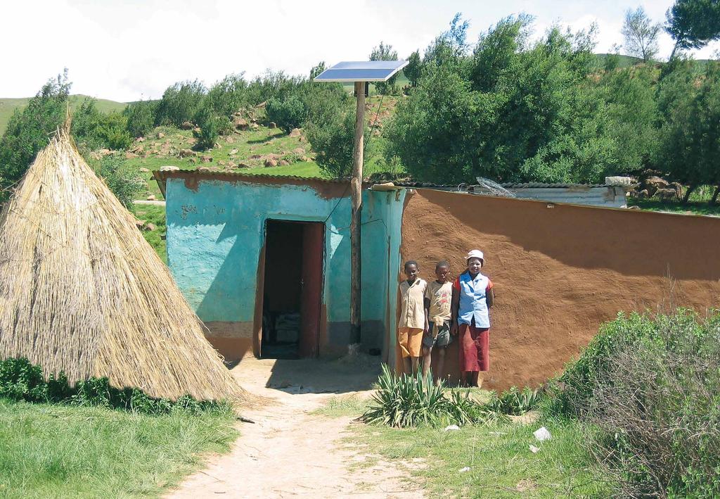
29 Steca SOLAR-HOME-SYSTEMS 56 57


30 - + SOLAR-HOME-SYSTEMS with Steca solar charge controllers Overview of devices A solar home system consists of a Steca solar charge controller, one or more solar modules, a battery and the connected loads. The Steca solar charge controllers control the energy flow of the entire system. They make sure that the solar module charges the battery quickly and effectively, but they also protect the battery against overcharging. If the loads discharge the battery, the solar charge controller, thanks to its precision in calculating the state of charge, switches off the load at exactly the right moment, thus protecting the battery from the dangers of deep discharge. Furthermore, Steca solar charge controllers are equipped with an intelligent battery monitoring system. The most effective charging method is selected according to the requirements of the batteries. The solar charge controller is the central controlling component in solar home systems, for it affects all the functions of the system. For this reason, it is important to choose a reliable and high-performance solar charge controller. The solar charge controller is connected directly to the battery using a cable as short as possible, and fixed to the wall near to the battery, so that it can be effectively cooled by the passing air flow. In principle, the battery is always connected to the solar charge controller first. Then the solar module array is connected to the solar module input of the solar charge controller. Only direct current loads are used in solar home systems. They are connected directly to the load output of the solar charge controller. This means the Steca solar charge controllers always show the battery s exact state of charge, and thus ensure optimal battery maintenance in all situations. Various Steca energy-saving lights, Steca solar cooling units, DC-to-DC converters and other loads can be used. Steca Solsum F 6-10 A; 12 / 24 V Steca PR A; 12 / 24 V Steca Solarix PRS A; 12 / 24 V Steca PR 2020 IP 20 A; 12 / 24 V Steca Solsum A; 12 / 24 V Steca Solarix A; 12 / 24 V Steca Solarix MPPT Maximum Power Point Tracker A; 12 / 24 V Steca Solarix MPPT Maximum Power Point Tracker A; 12 / 24 / 48 V Smartphone A B E C Key: A Solar modules B C Battery E Load Steca PF 240-H Solar refrigerator/freezer 240 l; 12 / 24 V Steca PF 166-H Solar refrigerator/freezer 166 l; 12 / 24 V Steca LED LEDs 4 W, 6 W, 8 W, 12 W 12 / 24 V Australia Sweden Burkina Faso Botswana 58 59

31 Steca NIGHT LIGHT SYSTEMS 60 61


32 NIGHT LIGHT SYSTEMS an important special application of solar home systems Night light systems match the structure of the solar home systems, but are equipped with any Basic, Classic or Advanced Steca charge controller, which automatically turns on the connected lights for a set time after sunset, and turns them off again the next morning at the latest. These systems are perfectly suited for street lamps and auto matic night-time lighting. Another special model makes these systems to the ideal solution for bus stops and similar applications. Operating in conjunction with a motion detector, the lamp is only turned on at night time when movement is detected in a specified area. After a few minutes, the light is then automatically turned off again. This function can be implemented with any Steca night light charge controller by connecting it to an external motion detector. Steca Solsum F 6-10 A; 12 / 24 V Steca Solarix PRS A; 12 / 24 V Steca Solsum A; 12 / 24 V Steca Solarix MPPT Maximum Power Point Tracker A; 12 / 24 V Greece Steca PR A; 12 / 24 V Steca PR 2020 IP 20 A; 12 / 24 V Steca Solarix A; 12 / 24 V Steca Tarom 45 A; 12 / 24 / 48 V A A B E B D E Steca Solarix MPPT Maximum Power Point Tracker A; 12 / 24 / 48 V Steca Tarom MPPT 6000-M Maximum Power Point Tracker 60 A; 12 / 24 / 48 V Accessories Loads C C A Steca PA IRS 1008/180 Motion detector Steca PA RC10 Programmiereinheit Steca LED LEDs 4 W, 6 W, 8 W, 12 W 12 / 24 V Duration of night light function Light on : All night After sunset Before sunrise Turn-on time delay Maximum light current B I : Steca Solsum F * 0-8 h* 10 A Steca Solarix PRS * 0-8 h* 30 A Steca Solsum * 0-8 h* 40 A Steca Solarix MPPT * 0-8 h* 20 A Steca PR 0-12 h 0-12 h 30 A Steca Solarix 0-12 h 0-12 h 40 A C G F Key: A Solar modules B C Battery D Motion detector E Load (12 V...24 V DC) F Load (115 V V AC) G Sine wave inverter I Relay Steca PR 2020 IP 0-12 h 0-12 h 30 A Steca Solarix 2020-x h (only with PA LCD1) 0-12 h 0-12 h 20 A Steca Tarom 4545, 0-12 h Steca Tarom h 0-12 h 45 A Steca Tarom MPPT 6000-M 0-12 h (only with external relay) 0-12 h 0-12 h 200 A The type of night light function selected must be specified in the order. * only for projects with larger order quantities

33 Steca INVERTER SYSTEMS 64 65


34 - + INVERTER SYSTEMS for both AC and DC Overview of devices DC AC Steca Solarix PRS A; 12 / 24 V Steca Solsum A; 12 / 24 V Steca AJ Sine wave inverter W 12 / 24 / 48 V Steca Solarix MPPT Maximum Power Point Tracker A; 12 / 24 V Steca PR A; 12 / 24 V Steca Solarix A; 12 / 24 V Steca Tarom 45 A; 12 / 24 / 48 V Steca Solarix PLI Hybrid-inverter W W Steca Xtender XTM, Steca Xtender XTS, Steca Xtender XTH, Hybrid-inverter W 12 / 24 / 48 V Inverter systems are designed as solar home systems. The central Steca solar charge controller ensures the battery is charged correctly and protects it against overcharging. In addition, a stand-alone inverter is connected directly to the battery in these systems so that AC appliances can be operated. If DC appliances are also used, they can be connected directly to the charge controller. An AC system can be created with a system voltage or battery voltage of 12 V, and also with 24 V or 48 V for greater capacities. The simple system concept makes installation quick and easy. Steca Solarix MPPT Maximum Power Point Tracker A; 12 / 24 / 48 V Steca Tarom MPPT 6000-S Steca Tarom MPPT 6000-M Maximum Power Point Tracker 60 A; 12 / 24 / 48 V Steca Solarix PI Sine wave inverter W 12 / 24 / 48 V A Key: A Solar modules B C Battery D Sine wave inverter E Generator junction box F Load (12 V...48 V DC) L Load (115 V V AC) B F D C L Philippines Italy DC AC 66 67

35 Steca Mini-grid And HYBRID-SYSTEMs 68 69


36 MINI-GRID for a smart energy mix Systemvarianten Autarkes Solar Wechselrichter System: Pure off-grid system (no AC input) PV as only energy source PV modules Electrical load 230V AC Battery Public grid Unterbrechnungsfreie Stromversorgung: Pure on-grid system No PV as only energy source, only grid Battery is charged from the grid whenever the grid is available Useful when grid fails as backup (10 ms switchover time) Electrical load 230V AC Battery What is a mini-grid? Mini-grids, which, depending on their size, are also known as micro-grids, have increasingly developed in many countries into a trend for off-grid electrification. With the aid of a so-called village power supply system, a range from individual households up to complete villages can be supplied with electricity in this way using photovoltaics units. From Steca s point of view a mini-grid is an autonomous grid which is centrally constructed independently of the public grid. The power classes mostly vary between at least 10 kwp and larger. Energy generation takes place to a great extent using DC photovoltaics units and is immediately centrally converted into AC current. The distribution and supply of the complete mini-grid then takes place exclusively or mainly using AC current, in many cases even three-phase. Advantages of mini-grids. The more powerful a PV off-grid system becomes, the more sense it makes to carry out the conversion from DC to AC at an early stage. It has practical advantages in particular for supplies over greater distances, as is the case in the electrification of a complete village. Significantly lower-priced components, such as cabling which possibly already exists, can be thus utilised, in particular as a result of the high voltages in the AC range. This mostly involves standard equipment which can be easily obtained and is familiar. PV modules Electrical load 230V AC Diesel generator Solar-Priorität mit Netzanschluss und/oder Generator: Grid-connected system or off-grid with AC generator (external source selector required if both are used) PV is priority, alternatively grid / generator can be selected as priority Optional charging from the grid / generator Battery Advantages of mini-grids with Steca Solarix PLI and This is now even easier and more affordable with the Steca Solarix PLI and NEW South Africa Steca Solarix PLI You can exploit all these advantages with the Steca Solarix PLI hybrid inverter and at the same time significantly reduce the complexity and costs of your system. The Steca Solarix PLI contains both the MPPT charge controller to which the solar modules are connected and the inverter which converts the generated power from DC to AC everything in one device. Even a diesel generator, the public grid or another AC source can all be alternately connected to the Steca Solarix PLI hybrid inverter. Where required, the system can thus be re-charged using this power source or, depending on the setting, the consumers can be supplied at times directly from this power source. Up to 9 inverters can be interconnected either in parallel and/or three-phase as a result of which systems of up to 21.6 kw or 45 kw can be realised. The parallel or three-phase interconnection takes place simply using a communication card for each device. The Steca Solarix PLI hybrid inverter thus has logistical advantages: Complex, powerful mini-grids can be easily and inexpensively achieved with only one model and one accessory. Warehousing, ordering and even the layout can thus be made significantly simplified
 Battery Public grid alternative genset Steca Solarix PLI Key: A Solar modules B Load (400 V")

37 MINI-GRID Now even easier and cheaper. Single-phase Mini-Grid-systems Three-phase Mini-Grid-systems B Key: A B C D E Solar modules Load (230 V AC) Battery Public grid alternative genset Steca Solarix PLI Key: A Solar modules B Load (400 V AC) C Battery D Public grid alternative genset E Steca Solarix PLI The simple and cost efficient solution for self consumption and hybrid system solutions Phase 1 Phase 2 Phase 3 Because grid feed-in is becoming increasingly uneconomical in many countries and involves higher expenditure, self consumption and power storage are becoming more important. The new Solarix PLI hybrid inverter is tailor-made for this application. The hybrid inverter is suited for an autonomous solar system, and for an uninterruptible power supply as well as for a solar system which can obtain power from the grid or from a diesel generator where required. The Solarix PLI is, however, also attractive for the traditional off-grid markets. Solar home systems generally dominate these markets. Here too there are new solutions. Several hybrid inverters can be connected in parallel and, as a result, village power supply systems ( mini-grids ) or even power systems for the supply of small factories and craftsman businesses ( small commercial systems ) are provided. C D B Belgium Up to 9 inverters can be connected in parallel and/or three-phase


38 HYBRID SYSTEMS Overview of devices DC AC Steca Tarom 45 A; 12 / 24 / 48 V Steca Xtender XTS Hybrid-inverter 700 W W 12 / 24 / 48 V Steca Tarom MPPT 6000-S Steca Tarom MPPT 6000-M Maximum Power Point Tracker 60 A; 12 / 24 / 48 V Steca Xtender XTM Hybrid-inverter W W 12 / 24 / 48 V The main feature of a hybrid system is the use of two or more different electricity sources. Alongside solar energy, photovoltaic hybrid systems generally employ a diesel generator, a wind turbine or the public grid as a further electricity source. The inverters used in hybrid systems, which have integrated battery chargers, supply the connected AC loads according to demand from the battery bank of solar energy or the second electricity source. These devices also allow the batteries to be recharged from the extra energy source. Photovoltaic hybrid systems offer the advantage that the solar generator does not have to be significantly oversized for periods of low sunlight. This avoids substantial costs. When selecting its energy source, the system always gives priority to the energy provided by the module. In combination with a controllable second source, the energy supply remains reliable and available 24 hours a day, all year round. Steca Power Tarom A; 12 / 24 / 48 V Steca Solarix PLI Hybrid inverter W W Steca Xtender XTH Hybrid-inverter W W 12 / 24 / 48 V Important features for single-phase and three-phase hybrid systems Combination of different power sources such as PV, wind, diesel generators 400 V AC three-phase and 230 V AC single-phase available 24 hours a day 12 V, 24 V or 48 V overall DC bus Automatic energy management based on the state of charge calculation of the battery, including automatic start of controllable power sources like e.g. diesel generators Optimised battery charging algorithm Optimised system efficiency through DC and AC bus Australia Germany Marocco 74 75

39 Steca BATTERY CHARGING SYSTEMS 76 77


40 BATTery charging systems efficient, intuitive and safe PRODUct overview Battery chargers Steca battery charging devices charge your batteries quickly and safely thanks to the processor-controlled charging processes. Fixed and programmable characteristic curves allow for flexibility during use. Highly efficient and advanced switching power supplies minimise energy losses. A wide range of features and ease of use make for trouble-free operation. Trickle charging system With the Steca trickle charging system, up to ten lead-acid batteries can be connected simultaneously without being connected in parallel. Thanks to the integrated Steca long-life cycle, lasting operational readiness is a given. A visual error message appears if a connected battery is faulty. This ensures that only flawless batteries are connected for reuse. Small charging units Even lead-acid batteries with small capacities need optimal charging. With our small charging units, we ensure this by controlled IU characteristic curves and a subsequent automatic trickle charging function. Parking space supply units For many applications, vehicles must be ready for use at all times. Regardless of whether your application involves a fire engine, a bus or a driverless transport system (DTS), you have to be able to rely on your system. Parking space supply units from Steca provide the optimum charging technology. Our devices are already providing successful and reliable service in lots of areas. They are used at many local public transport depots, as stand-by systems in fire brigades and for charging driverless transport systems (DTS) during ongoing operation. The bus depot is one of the main areas of application for parking space supply units. Parking space supply systems are available as individual devices or as charging posts. They charge the batteries of the connected vehicle and guarantee a charged battery at all times. The parking space supply system also charges parallel loads in the bus. This protects the battery set and improves the service lives of the batteries. With their internal communication interfaces, Steca parking space supply units are best prepared for application in depot management systems. We supply all necessary components as well as bus identification modules or our Steca gateway which transfers the data from the bus and charging post to depot management software. For example, a heating signal can be sent to the bus and the feedback can be monitored. The depot management system can display and process the battery charging parameters, parking space data and bus number. Depot supply for bus depots and fire stations Steca battery charging technology stands out from the start thanks to its high quality and durability. For decades we have been developing efficient and user-friendly charging technology in cooperation with leading battery manufacturers and institutes in order to allow you to use your batteries safely. Our main focus is on making the charging devices easy to use and achieving the best battery charge possible. The charging process is fully automatic and the user has access to information about the charging behaviour of their battery at all times. Steca battery charging technology can even test batteries in terms of their charging capacity and remaining capacity. This way, the user knows whether or not the battery is still working efficiently and if it is suitable for the planned application. This avoids unexpected battery failures and the resulting costs. In addition to battery charging devices and testing devices, we provide parking space supply systems for bus depots for example. If you are planning to construct a battery charging station, you will find that the charging technology in Steca battery charging devices conforms to all relevant standards. Consultation and planning In connection with our battery chargers our staff will be glad to give you expert advice on all questions regarding batteries and battery use. We focus on finding the best solution for your application. This way, we can keep a constant eye on the applicable standards for the application in question and implement them. Our engineers and partners can plan your ideal configuration and help you draw up specifications. After-sales service We are constantly expanding our network of service partners for distribution, maintenance and repairs. This allows us to react to your enquiries as quickly as possible. We are also happy to advise you over our customer hotline. Examples of application Mobile charging points: warning trailers, trolleys and supporting frames Battery chargers in use Parking space supply units for bus depots 78 79
41 MAT 860 Processor-controlled charger for lead-acid batteries MAT 861 Processor-controlled charger for lead-acid batteries The battery charger Stecamat 860 is available in a dust and hose-proof housing. The processor-controlled charging process ensures gentle and rapid charging of the battery. The Stecamat 860 also enables the processing of damaged or totally discharged batteries, ensuring long service life. A LED provides rapid information on the state of charge. Maximum flexibility is provided by the extensive features. This and the easy handling of the device make for trouble-free operation. The battery charger Stecamat 861 is available in a dust and hose-proof housing. The processor-controlled charging process ensures gentle and rapid charging of the battery. For individual adjustment of current, voltage, time and the ideal monitoring of the battery, the Stecamat 861 battery charger has a selection of preset battery profiles and the option of entering new battery profiles. The Stecamat 861 also enables the processing of damaged or totally discharged batteries, ensuring long service life. A backlit display provides rapid information on the state of charge. Maximum flexibility is provided by the extensive features. This and the easy handling of the device make for trouble-free operation IP 65 jet waterproof case Half the charging time compared to simple, non-controlled chargers with the same rated current Optimal for charging batteries with liquid electrolyte and solid gel / absorbed electrolyte (AGM) Suitable for totally discharged batteries Constant battery operational readiness through integrated trickle charge Charging below the gassing voltage Optimal charging of damaged batteries Potential-free contact for ventilator control of the battery room venting system Protection in the case of wrong or damaged batteries Battery overcharge protection Charger output protected against short circuits, reverse polarity and overvoltage Display Multi-coloured LED shows operating statuses Operation Mains grid switch Interfaces Control contact for ventilation control system in accordance with DIN EN Options IO box with mains plug and relay for ventilator control Technical data Charging rated voltage 12 V 24 V 48 V Charging current 50 A 35 A 18 A End-of-charge voltage 14.4 V 28.8 V 57.6 V Trickle charge voltage 13.8 V 27.6 V 55.2 V Characteristic curve UoIUoIU Grid voltage 230 V AC ± 10 % Grid frequency 50 Hz (45 Hz Hz) Mains electricity 3.7 A (230 V) 5.5 A (230 V) Discharge current during grid failure 1 ma Protection class I Casing / ingress protection aluminium / plastic, IP 65 Ambient temperature -40 C C Cooling convection Dimensions X x Y x Z 226 x 535 x 127 mm Weight approx kg Besides preset battery profiles there is the option of entering new battery profiles IP 65 jet waterproof case Half the charging time compared to simple, non-controlled chargers with the same rated current Optimal for charging batteries with liquid electrolyte and solid gel / absorbed electrolyte (AGM) Adjustable rated capacity determines the charging current Suitable for totally discharged batteries Constant battery operational readiness through integrated trickle charge Charging below the gassing voltage Optimal charging of damaged batteries Potential-free contact for ventilator control of the battery room venting system Protection in the case of wrong or damaged batteries Battery overcharge protection Charger output protected against short circuits, reverse polarity and overvoltage Surge protection in on-board power supplies Display Multifunction graphical LCD with backlighting for voltage, current, charged capacity, charging phase, menu Operation Mains grid switch Four cursor buttons for menu selection Interfaces Control contact for ventilation control system in accordance with DIN EN Technical data 535 Charging rated voltage 12 V 24 V 48 V Charging current 50 A 35 A 18 A End-of-charge voltage 14.4 V 28.8 V 57.6 V Trickle charge voltage 13.8 V 27.6 V 55.2 V Characteristic curve UoIUoIU Grid voltage 230 V AC ± 10 % Grid frequency 50 Hz (45 Hz Hz) Mains electricity 3.7 A (230 V) 5.5 A (230 V) Discharge current during 1 ma grid failure Protection class I Casing / ingress protection aluminium / plastic, IP 65 Ambient temperature -20 C C Cooling Convection Dimensions X x Y x Z 226 x 535 x 127 mm Weight approx kg Options IO box with mains plug and relay for ventilator control 80 81

42 MAT 861 ES Processor-controlled charger / discharger for lead-acid batteries The Stecamat 861 ES battery charger features a discharging stage of 140 W. It can recharge 12 V batteries with 720 W of power or discharge, charge and evaluate batteries in one automated test cycle. For individual adjustment of current, voltage, time and the ideal monitoring of the battery, the Stecamat 861 ES battery charger has a selection of preset battery profiles and the option of entering new battery profiles. The Stecamat 861 ES also enables the processing of damaged or totally discharged batteries, ensuring long service life. A backlit display provides rapid information on the state of charge. Maximum flexibility is provided by the extensive features. This and the easy handling of the device make for trouble-free operation. MAT 820 Processor-controlled charger for lead-acid batteries The battery charger Stecamat 820 is available in a light, compact housing. The processor-controlled charging process ensures gentle and rapid charging of the battery. The current, voltage, time and ideal monitoring of the battery are individually adjusted by the setting of the rated capacity. The Stecamat 820 also enables the processing of damaged or totally discharged batteries, ensuring long service life. A LED provides rapid information on the state of charge. The wide range of features make for high flexibility of use. This and the easy handling make for trouble-free operation, even when wearing gloves. 127 IP 65 jet waterproof case Battery processing for wet, gel and AGM batteries possible Charges 12 V lead-acid batteries (max. 50 A) Adjustable rated capacity determines the charging current Charging below the gassing voltage Features 2 pre-set and 4 programmable charging characteristics Automated testing for 12 V lead-acid batteries (charge discharge charge) 12 V discharging stage with 10 A discharge current (you can select between 2.5 A, 5 A and 10 A) Capacity detection of 12 V lead-acid batteries Suitable for treating deep-discharged batteries Potential-free contact for ventilator control of the battery room venting system Protection in the case of wrong or damaged batteries Battery overcharge protection Charger output protected against short circuits, reverse polarity and overvoltage Surge protection in on-board power supplies Display Multifunction graphical LCD with backlighting for voltage, current, charged capacity (charging), spent capacity (discharging), charging phase, test phase, menu Operation Mains grid switch Four cursor buttons for menu selection Capacity test cycle: charge, discharge, charge Interfaces Control contact for ventilation control system in accordance with DIN EN Technical data Charging rated voltage 12 V Charging current 50 A End-of-charge voltage 14.4 V Trickle charge voltage* 13.8 V Max. rated discharge voltage 12 V Discharge cut-off voltage 10.5 V (10 V V adjustable) Discharge current selectable: 2.5 A / 5 A / 10 A Characteristic curve UoIUoIU (charging), UoIUa (testing) Capacity test cycle charging / discharging / charging Grid voltage 230 V AC ± 10 % Grid frequency 50 Hz (45 Hz Hz) Mains electricity 3.7 A (230 V) Discharge current during grid failure 1 ma Protection class I Casing / ingress protection aluminium / plastic, IP 65 Ambient temperature -20 C C Cooling convection Half the charging time compared to simple, non-controlled chargers with the same rated current Optimal for charging batteries with liquid electrolyte and solid gel / absorbed electrolyte (AGM) Adjustable rated capacity determines the charging current Suitable for totally discharged batteries Constant battery operational readiness through integrated trickle charge Ready for operation in just a few minutes Charging below the gassing voltage Optimal charging of damaged batteries Protection in the case of wrong or damaged batteries Battery overcharge protection Charger output protected against short circuits, reverse polarity and overvoltage Display Multi-coloured LED shows operating statuses Operation Adjustable rated capacity via rotary switch Interfaces Control contact for ventilation control system in accordance with DIN EN Options IO box with mains plug and relay for ventilator control Technical data Charging rated voltage 12 V 24 V 48 V Charging current 50 A 35 A 18 A End-of-charge voltage 14.4 V 28.8 V 57.6 V Trickle charge voltage 13.8 V 27.6 V 55.2 V Characteristic curve UoIUoIU Grid voltage 230 V AC ± 10 % Grid frequency 50 Hz Mains electricity 3.7 A (230 V) 5.5 A (230 V) Discharge current during grid failure 1 ma Protection class I Casing / ingress protection plastic, IP 20 Ambient temperature -20 C C Cooling regulated fan Dimensions X x Y x Z 248 x 429 x 128 mm Weight approx. 6 kg Options IO box with mains plug and relay for ventilator control Dimensions X x Y x Z Weight * only for charging programme 226 x 535 x 127 mm approx kg 82 83


43 MAT 821 Processor-controlled charger for lead-acid batteries The battery charger Stecamat 821 is available in a light, compact housing. The processor-controlled charging process ensures gentle and rapid charging of the battery. For individual adjustment of current, voltage, time and the ideal monitoring of the battery, the Stecamat 821 battery charger has a selection of preset battery profiles and the option of entering new battery profiles. The Stecamat 821 also enables the processing of damaged or totally discharged batteries, ensuring long service life. A backlit display provides rapid information on the state of charge. The wide range of features make for high flexibility of use. This and the easy handling of the device make for trouble-free operation. MAT 862 Processor-controlled charger for lead-acid batteries with communication feature The battery charger Stecamat 862 charges the battery gently and quickly thanks to a processor-controlled charging process. The Stecamat 862 thus enables the processing of damaged or totally discharged batteries, ensuring long service life. The IP 65-certified dust and splash-proof housing allows for outdoor installation. Data can be read and processed centrally thanks to the integrated RS-485 interface. With this communication interface, the various charging parameters can be adjusted and the charging current can be increased to a maximum of 35 A. The integrated interface allows for communication with buses that are equipped with an integrated bus identification module (BIM). 127 Besides preset battery profiles there is the option of entering new battery profiles Half the charging time compared to simple, non-controlled chargers with the same rated current Optimal for charging batteries with liquid electrolyte and solid gel / absorbed electrolyte (AGM) Adjustable rated capacity determines the charging current Suitable for totally discharged batteries Constant battery operational readiness through integrated trickle charge Ready for operation in just a few minutes Charging below the gassing voltage Optimal charging of damaged batteries IP 65 jet waterproof casing Half the charging time compared to simple, non-controlled chargers with the same rated current Optimal for charging batteries with liquid electrolyte and solid gel / absorbed electrolyte (AGM) Suitable for totally discharged batteries Constant battery operational readiness through integrated trickle charge Charging below the gassing voltage Optimal charging of damaged batteries Communication with bus identification module for vehicle identification, heating control and query of ignition status Interface for bidirectional communication Protection in the case of wrong or damaged batteries Battery overcharge protection Charger output protected against short circuits, reverse polarity and overvoltage Protection in the case of wrong or damaged batteries Battery overcharge protection Charger output protected against short circuits, reverse polarity and overvoltage 226 Display Multifunction graphical LCD with backlighting for voltage, current, charged capacity, charging phase, menu Operation Four cursor buttons for menu selection Interfaces Control contact for ventilation control system in accordance with DIN EN Options IO box with mains plug and relay for ventilator control Technical data Charging rated voltage 12 V 24 V 48 V Charging current 50 A 35 A 18 A End-of-charge voltage 14.4 V 28.8 V 57.6 V Trickle charge voltage 13.8 V 27.6 V 55.2 V Characteristic curve UoIUoIU Grid voltage 230 V AC ± 10 % Grid frequency 50 Hz (45 Hz Hz) Mains electricity 3.7 A (230 V) 5.5 A (230 V) Discharge current during grid failure 1 ma Protection class I Casing / ingress protection plastic, IP 20 Ambient temperature -20 C C Cooling regulated fan Dimensions X x Y x Z 248 x 429 x 128 mm Weight approx. 6 kg Displays Multi-coloured LED shows operating states Operation Charging parameters adjustable via RS-485 Interfaces RS-485 for connection to the depot management software Technical data Charging rated voltage 24 V Charging current 20 A (max. 35 A) End-of-charge voltage 27.6 V Trickle charge voltage 27.2 V Characteristic curve UoIUoIU Grid voltage 230 V AC ± 10 % Grid frequency 50 Hz (45 Hz Hz) Mains electricity 4.0 A (230 V) Discharge current during 1 ma grid failure Protection class I Casing / ingress protection aluminium / plastic, IP 65 Ambient temperature -40 C C Cooling convection Dimensions X x Y x Z 226 x 535 x 127 mm Weight approx kg 84 85


44 Use the synergies by the know-how from different business segments and product areas for which we deliver electronic components and modules: Steca EMS PROVIDER HOME APPLIANCES & CONSUMER ELECTRONICS - Refrigerators and freezers - Electrical equipment - Heating controllers - Cable assemblies AUTOMOTIVE - Controls for auxiliary heating systems and sliding car roofs - Power distribution modules / fuse modules - LED lighting systems for car interieur Steca is certified according to - ISO ISO ISO ISO/TS Steca is audited according to - EN ISO MEDICAL TECHNOLOGY - Dental technology for practice and laboratory facilities - Mobile heart defibrillators - Microscopy systems - Pipette systems for analysing solids and fluids INDUSTRIAL ELECTRONICS - Step motor controls - Pump controls - Sensors - Welding machines - Packing machines - Control units (HMI) Steca guarantees top quality, safety and reliability, and places considerable emphasis on environmental compatibility during the development, construction, manufacture and distribution of its products. In order to reach these quality targets, Steca employs quality control and quality improvement strategies. SOLAR & ENERGY - Grid inverters for residential systems - PV off grid - s - Solar thermal controllers - Heating and domestic hot water controllers - Battery charging systems 86 87


45 Steca International Network For you on-site. With two locations, Steca can combine the quality and flexibility of a German provider with the advantages of low-cost production abroad. Enthusiastic and motivated staff on site, an experienced international and multilingual sales team as well as many sales partners and authorised wholesalers worldwide make Steca a significant company on both a national and international scale. Memmingen Germany Foundation employees - Research and development - Industrialisation - Marketing, sales, puchasing - Production - Service Steca is part of the PRIMEPULSE network. PRIMEPULSE is the management holding company and group within which the experienced founders and managers of TecDAX-listed CANCOM SE and the AL-KO Group, which developed as a family business, actively guide their equity investments to success using their digital expertise and entrepreneurial skill. The efficient network includes international companies such as CANCOM, AL-KO and Stemmer Imaging. The PRIMEPULSE Group operates in the IT, vision technology, electronics, e-business, automotive, air technology, garden tech and real estate segments. As a strategic investor, PRIMEPULSE takes a long-term, value-oriented approach to equity investment and is a safe long-term partner for companies and real estate projects. Saedinenie Bulgaria Foundation employees - Industrialisation - Purchasing - Production 88 89

8331-8558-0 F")

46 Steca Elektronik GmbH Mammostraße Memmingen Germany T +49-(0) F +49-(0) info@steca.com facebook.com/stecaelektronik youtube.com/c/stecaelektronik 90
SOLAR CHARGE CONTROLLERS
 Steca Tarom MPPT 6000-S, 6000-M The new design for the Steca Tarom sets new standards in this power class. The graphic display informs the user of all important system data. The data are saved by the integrated
2.1.Steca Solsum. Solsum 8.0c. Solar Charge Controller. Solsum 5.0c. Solsum 6.6c. Solsum 10.10c. 8.8c
 2.1.Steca Solar Charge Controller 5.0c 8.0c 6.6c 8.8c 10.10c The Steca F-Line continues the huge success of one of the most used SHS controllers. With a power range of up to 10 A at automatically recognized
Current Automation Catalogue
 Current Automation Catalogue Page 1 Visit our website for more indebt info on this product range Current Automation Catalogue Page 2 STECA Steca Solar Charge Controllers Steca Solar Charge Controllers
ENGLISH PV OFF F GRID BATTERY
 ENGLISH PV OFF F GRID + TTERY HRGING SYSTEMS 2 3»apture the sun s energy using intelligent systems from Steca.«Two billion people in rural areas still have no access to an electricity grid. Steca has set
SOLAR POWER OFF-GRID RANGE 2013
 SOLAR POWER OFF-GRID RANGE 2013 www.yhipower.co.nz1 Areas of application: SUNNY ISLAND 5048 The Island manager Commissioning just takes a few minutes: For Sunny Island 5048, the settings needed for operation
NEW SOLAR CHARGE CONTROLLERS
 190 SOLAR CHARGE CONTROLLERS Steca Solarix 2020-x2 Dual battery charge controller The Steca Solarix 2020-x2 is a state-of-the-art dual battery charge controller that is ideal for use in leisure applications.
ENGLISH. pv OFF grid
 ENGLISH pv OFF grid 2 3»apture the sun s energy unsing intelligent systems from Steca.«Two billion people in rural areas still have no access to an electricity grid. Steca has set itself the target of
Installation and operating instructions. Solar charge controller MPPT 10 A / 20 A Z Z
 Installation and operating instructions Solar charge controller MPPT 10 A / 20 A EN 1 Contents 1. About these instructions... 3 1.1 Applicability... 3 1.2 Users... 3 1.3 Description of symbols... 3 2.
Steca Elektronik SOLARIX PLI
 Steca Elektronik Inverter / Charger with MPPT charge controller All-in-one: 5 kw pure sine wave inverter (10 kw up to 5 s) 80 A MPPT charge controller (max. 145 Voc) 60 A charger from AC source (grid or
Steca Elektronik INVERTER / CHARGER WITH MPPT: SOLARIX PLI
 Steca Elektronik INVERTER / CHARGER WITH MPPT: 5000-48 Inverter / Charger with MPPT charge controller All-in-one: 5 kw / 5 kva pure sine wave inverter (10 kw / 10 kva up to 5 s) 80 A MPPT charge controller
PRICE LIST STECA PV OFF GRID PRODUCTS 1
 PRICE LIST STECA PV OFF GRID PRODUCTS 1 PRICE LIST STECA PV OFF GRID PRODUCTS 2 Steca Tarom 4545 744236 12/24V, 45A w. LCD 16 270,00 270,00 Steca Tarom 4545-48 744242 12/24V/48V, 45A w. LCD 16 300,00 300,00
Steca Solarix PLI. Inverter / Charger with Solar Charge Controller. Installation and operating instructions. Download manual at
 Inverter / Charger with Solar Charge Controller Steca Solarix PLI Installation and operating instructions GB Z03 18.20 Download manual at www.steca.com Table of Contents About this manual... 1 Purpose...
User Manual. Solar Charge Controller 3KW
 User Manual Solar Charge Controller 3KW 1 CONTENTS 1 ABOUT THIS MANUAL... 3 1.1 Purpose... 3 1.2 Scope... 3 1.3 SAFETY INSTRUCTIONS... 3 2 INTRODUCTION... 4 2.1 Features... 4 2.2 Product Overview... 5
Installation and operating instructions. Solar charge controller Solarix MPPT 1010 and Z Z
 Installation and operating instructions Solar charge controller Solarix MPPT 1010 and 2010 EN 730927 Z04 1440 730927 Z04 1440 1 Contents 1. About these instructions...3 1.1 Applicability...3 1.2 Users...3
Solar inverter AX-series
 Power Supplies Inverters Solar inverter AX-series 1-5kVA Multifunctional inverter NEU / NEW PV inverter PV / Battery Charger with 3-stage charge Battery-backed power supply Sine wave inverter with charging
Phocos CML-V2. Solar charge controller. User Manual (English) Dear customer,
 Dear customer,") Phocos CML-V2 Solar charge controller User Manual (English) Dear customer, Thank you very much for buying this Phocos product. Please read the instructions carefully and thoroughly before using the product.
Phocos CML-V2 Solar charge controller User Manual (English) Dear customer, Thank you very much for buying this Phocos product. Please read the instructions carefully and thoroughly before using the product.
2008/2009 Product Catalog
 2008/2009 Product Catalog in English The World s Leading Solar Controllers & Inverters Our company Morningstar Corporation, founded in 1993, is the world s leading supplier of photovoltaic (PV) controllers.
Installation and Operating Instructions. MPPT Solar System Controller ISC3040
 Installation and Operating Instructions MPPT Solar System Controller ISC3040 ABOUT THIS MANUAL These operating instructions come with the product and should be kept with it as a reference to all user s
Inverter / Charger Accessory for Steca Solarix PLI Phase / Parallel Kit. Installation and operating instructions Z01 17.
 Inverter / Charger Accessory for Steca Solarix PLI 5000-48 3-Phase / Parallel Kit Installation and operating instructions GB Z01 17.31 Table of Contents About this Manual... 2 Purpose... 2 Scope... 2 Keywords
User Manual Solar Charge Controller 3KW
 User Manual Solar Charge Controller 3KW Version: 1.3 CONTENTS 1 ABOUT THIS MANUAL... 1 1.1 Purpose... 1 1.2 Scope... 1 1.3 SAFETY INSTRUCTIONS... 1 2 INTRODUCTION... 2 2.1 Features... 2 2.2 Product Overview...
Empower the World with Photovoltaics
 www.klinkmann.com Empower the World with Photovoltaics Solutions for photovoltaic power supply - for professional and for housing applications. Schematic Diagram of the Smart Off-Grid Systems (for applications
SK-10. Features. Solar Charge Controller User Manual. Important Safety Information
 SK-10 Solar Charge Controller User Manual 12V/24V 10Amp Dear Users: Thank you for selecting our product. Please read this manual carefully before you use this product. This product is of cutting edge design,
Advanced Hybrid Wind / Solar Charge Controller. User Manual
 Advanced Hybrid Wind / Solar Charge Controller User Manual Safety 1. Please read the instructions carefully prior to product use or installation and refer back to them throughout the installation. 2. This
Steca Solarix PLI. Inverter / Charger with Solar Charge Controller. Installation and operating instructions. Download manual at
 Inverter / Charger with Solar Charge Controller Steca Solarix PLI Installation and operating instructions GB Z02 18.05 Download manual at www.steca.com Table of Contents About this manual... 1 Purpose...
2006/2007 Product Catalog. The World s Leading SOLAR Controllers
 2006/2007 Product Catalog The World s Leading SOLAR Controllers OUR COMPANY Morningstar Corporation, founded in 1993, is the world s leading supplier of photovoltaic (PV) controllers. In 2005 we shipped
Instruction of Solar Charge Controller. User s Manual
 Instruction of Solar Charge Controller User s Manual 12V/24V 30A Dear Users: Thank you for selecting our product. Please read this manual carefully before you use this product. The controller is for off-grid
One-Stop Service: Monitoring and Managing.
 One-Stop Service: Monitoring and Managing. The highest quality from the market leader Solar-Log devices are the most accurate and reliable data loggers on the market. Offer your customers high-quality
Rover Series. Rover 20A 40A Maximum Power Point Tracking Solar Charge Controller
 Rover Series Rover 20A 40A Maximum Power Point Tracking Solar Charge Controller 0 2775 E. Philadelphia St., Ontario, CA 91761 1-800-330-8678 Version 1.5 Important Safety Instructions Please save these
Instruction of Solar Charge Controller. User s Manual
 Instruction of Solar Charge Controller User s Manual 12V/24V 10A/20A Dear Users: Thank you for selecting our product. Please read this manual carefully before you use this product. 0 The controller is
SMART 1000 / 2000 SERIES
 SMART 1000 / 2000 SERIES DC/AC Mobile Hybrid Power Systems AC INVERTER VOLTAGE ADJUSTMENT 220-240V ON OFF 0 100 220-240V / 50Hz C.P. 1.2kW / S.P. 3.3kW 200 AC VOLTAGE Mobile Solutions for Renewable Energy
DATASHEET TECHNICAL INFORMATION. Stationary applications, island solutions
 Multi-Grid - Lithium-ion Battery System ON/OFF-GRID POWER SUPPLY WITH INVERTER SAFE, TURN-KEY READY 24 V DC / 48 V DC - 4 to 12 kwh Scalable and Modular-System (24 V DC / 48 V DC) High energy and power
The Traveler Series: Adventurer
 The Traveler Series: Adventurer RENOGY 30A Flush Mount Charge Controller Manual 2775 E. Philadelphia St., Ontario, CA 91761 1-800-330-8678 Version: 2.2 Important Safety Instructions Please save these instructions.
Ningbo Star Solar Co.,Ltd Tel:(86) Fax:(86)
 Fax:(86)") Tracer MPPT Solar charge controller Tracer series 40A mppt solar controller adopts MPPT technology (Maximum Power Point Tracking). The advanced tracking algorithm make the solar panel operate at ideal
Tracer MPPT Solar charge controller Tracer series 40A mppt solar controller adopts MPPT technology (Maximum Power Point Tracking). The advanced tracking algorithm make the solar panel operate at ideal
Installation and Operating Instructions. Solar System Controller ISC3030
 Installation and Operating Instructions Solar System Controller ISC3030 ABOUT THIS MANUAL These operating instructions come with the product and should be kept with it as a reference to all user s of the
400W Solar Charger Maximum Power Point Tracker
 Page 1 of 8 This revolutionary maximum power point tracker solar charger was designed using the technology that won GSL Electronics the prestigious 2008 EDN Innovation award. A simple, compact and low
Instruction of Solar Charge Controller. User s Manual
 Instruction of Solar Charge Controller User s Manual 12V/24V 30A Dear Users: Thank you for selecting our product. Please read this manual carefully before you use this product. 0 The controller is for
XTRA-N SERIES. New MPPT Solar Charge Controller. Product models XTRA1206N/XTRA2206N XTRA1210N/XTRA2210N XTRA3210N/XTRA4210N.
 -N SERIES New MPPT Solar Charge Controller Product models 1206N/2206N 1210N/2210N 3210N/4210N Product portfolio The -N series integrate the latest design philosophy, as the main part which is the solar
SMPPT. Solar Charge Controller with Maximum Power Point Tracking. Installation & Operation Manual
 SMPPT Solar Charge Controller with Maximum Power Point Tracking 10A/20A/30A 12V/24V Installation & Operation Manual 1 Dear Consumer: Thank you very much for using our product! We will offer you the permanent
The Traveler Series TM : Adventurer
 The Traveler Series TM : Adventurer 30A PWM Flush Mount Charge Controller w/ LCD Display 2775 E. Philadelphia St., Ontario, CA 91761 1-800-330-8678 Version: 3.4 Important Safety Instructions Please save
Smart-UPS On-Line Lithium Ion UPS 230V. Single-phase, double conversion online UPS with Li-Ion batteries and advanced management features
 Smart-UPS On-Line Lithium Ion UPS 230V Single-phase, double conversion online UPS with Li-Ion batteries and advanced management features A UPS developed for availability of your most critical loads under
Engineered power. Inverter-chargers. Inverters. MPPT solar charge controllers. Battery chargers. Battery monitoring.
 Battery chargers Inverter-chargers Battery monitoring Engineered power Inverters Battery splitters Battery separators MPPT solar charge controllers DC/DC converters SWISS made power Company Studer Innotec
Your new LM controller is a state-of-the art device which was developed in accordance with the latest
 CAP LM-series Solar charge controller User Manual Thank you very much for buying this CAP product. Please read the instructions carefully and thoroughly before using the products. Your new LM controller
Solar Inverter 3kW-8kW Inverter (off-grid)
") Solar Inverter 3kW-8kW Inverter (off-grid) Max. DC Power Data: 5.67kW-11.52kW Max. DC Voltage: 200V-400V Max. AC Power: 3kW-8kW Output AC Voltage: 220V (Range: 209-231V) Frequency: 50, 60Hz (49.5-60.6Hz)
Solar Inverter 3kW-8kW Inverter (off-grid) Max. DC Power Data: 5.67kW-11.52kW Max. DC Voltage: 200V-400V Max. AC Power: 3kW-8kW Output AC Voltage: 220V (Range: 209-231V) Frequency: 50, 60Hz (49.5-60.6Hz)
Mass Combi Ultra 24/ (230 V)
") Mass Combi Ultra 24/3500-100 (230 V) Product code: 38023500 The Mass Combi Ultra series comprises several models, varying from 3000 W to 3500 W. For higher capacities up to 35 kw the Combi Ultra can be
Mass Combi Ultra 24/3500-100 (230 V) Product code: 38023500 The Mass Combi Ultra series comprises several models, varying from 3000 W to 3500 W. For higher capacities up to 35 kw the Combi Ultra can be
ALIANT ULTRALIGHT BATTERY is a product by ELSA Solutions S.r.l
 Pg. 2 / 32 LIFEPO4 BATTERY CHARGER CB1203 3 Amp charger / Xtra Small Compact and inexpensive battery charger!!! Use with Aliant X, X-P and YLP series / from 2 to 20Ah ACCESSORIES This battery charger is
INVERTER. MECHANICAL DATA Steel with powder paint Dimension (mm) 527 x 228 x 190 Net Weight (kgs) 18 STANDAR. Cont output power at 20ºC. Cos φ 0.
 527 x 228 x 190 Net Weight (kgs) 18 STANDAR. Cont output power at 20ºC. Cos φ 0.") 12 Vdc 1500 W 2000 VA Overload >125% 60 s >110% 15 min Efficiency 89% Standby adjustment 0.2% - 2% Rated Power Zero load power 14 W Zero load power (power save mode) 3.5 W 10 A 12 Vdc Max Output current
12 Vdc 1500 W 2000 VA Overload >125% 60 s >110% 15 min Efficiency 89% Standby adjustment 0.2% - 2% Rated Power Zero load power 14 W Zero load power (power save mode) 3.5 W 10 A 12 Vdc Max Output current
Duo Battery Charge Controller
 Duo Battery Charge Controller RENOGY 10A 20A Pulse Width Modulation Solar Charge Controller Manual 1 2775 E. Philadelphia St., Ontario CA 91761 1-800-330-8678 Version: 1.2 Important Safety Instructions
Installation and Operating Instructions. Solar System Controller ISC3020
 Installation and Operating Instructions Solar System Controller ISC3020 ABOUT THIS MANUAL These operating instructions come with the product and should be kept with it as a reference to all user s of
SC-Max 48V series. User Manual. Solar Charge Controller 30A
 SC-Max 48V series Solar Charge Controller 30A User Manual Contents 1 Description of function 2 Safety Instructions and Waiver of Liability 2.1 Safety 2.2 Liability Exclusion 3 Dimensions 4 Optional 4.1
Eclipse Solar Suitcase
 Eclipse Solar Suitcase Renogy 100W 200W 2775 E. Philadelphia St., Ontario, CA 91761 1-800-330-8678 Version 1.0 Important Safety Instructions Please save these instructions. This manual contains important
THE ENERGY STORAGE EXPERTS
 TPS POWER STORAGE The all-rounder for grid networks and industry Built to last 30 years 1C charging speed The safest cell technology THE ENERGY STORAGE EXPERTS WE HAVE A THEN FOR ANY WHEN. Our battery
Plug Into the Current Future
 Green Energy Solutions & Electric Mobility Plug Into the Current Future enquiries@freedomwon.co.za +27(0)71 890 9958 +27(0)82 256 7430 www.freedomwon.co.za Leading Lithium (LiFePO4) battery energy storage
photovoltaikforum.com
 SolarMax 20C/25C/30C/35C Proven reliability. Proven reliability. Sputnik Engineering commissioned the first SolarMax PV central inverters in 1992. Since then thousands of central inverters have been put
User Manual. 3kW Hybrid PV Inverter HX-3000
 User Manual 3kW Hybrid PV Inverter HX-3000 Table Of Contents 1. Introduction...1 2. Important Safety Warning...2 3. Unpacking & Overview...4 3-1. Packing List... 4 3-2. Product Overview... 4 4. Installation...5
Plug Into the Current Future
 Green Energy Solutions & Electric Mobility Plug Into the Current Future enquiries@freedomwon.co.za +27(0)71 890 9958 +27(0)82 256 7430 www.freedomwon.co.za Leading Lithium (LiFePO4) battery energy storage
Solar MPPT Battery Charging Controller
 ( New Model, Aug. 2015, Timer attached ) Solar MPPT Battery Charging Controller Free standing with Hybrid function ( Only for Li-Ion / Li-Polymer Battery ) ( Load Output Control Timer Equipped ) 1. FEATURES
SMT. Installation and Operation Manual. Model:SMT WITH MPPT TECHNOLOGY
 SMT WITH MPPT TECHNOLOGY Installation and Operation Manual Model:SMT SMT Dimensions Specification Summary System Voltage 12 V/24V Rated Battery Current 12V, 5A 8A 10A 15A 20A 25A 24V, 5A 8A 10A 15A Rated
10A 15A 25A 40A 60A 20A 30A
 12V-60A 24V-30A New robust and compact casing 3 Completely isolated battery outputs Easy wiring and connections thanks to the Winsta (Wago) and Phoenix contact connectors Digital management with up to
400W Solar Charger Maximum Power Point Tracker
 MPPT2-2P Page of 8 This revolutionary maximum power point tracker solar charger was designed using the technology that won GSL Electronics the prestigious 2008 EDN Innovation award. A simple, compact and
3500W Solar Battery Charger Maximum Power Point Tracker
 Page 1 of 8 This revolutionary maximum power point tracker solar charger was designed using the technology that won GSL Electronics the prestigious EDN Innovation Awards 08 and 09 and the Greentech Consensus
The Traveler Series: Wanderer
 The Traveler Series: Wanderer RENOGY 30A PWM Charge Controller Manual 2775 E. Philadelphia St., Ontario, CA 91761 1-800-330-8678 1 Version: 2.3 Important Safety Instructions Please save these instructions.
Green Inverters from. Solar inverters. for Asia. Solar inverters. for Europe. Solar inverters. for America. Solar inverters.
 Solar inverters for Asia Solar inverters for Europe Solar inverters for America Solar inverters for the Earth Green Inverters from GROWATT NEW ENERGY CO., LTD No. Building, Xicheng Industrial Zone Bao
PWM Charge Controller with LCD Display 30A. User Manual
 PWM Charge Controller with LCD Display 30A User Manual 1 Product Features 1. 12V/ 24 V system voltages are automatically recognized. 2. Charging program options for sealed, GEL and flooded lead-acid batteries
Bioenno 400 Power Pack BPP-M400
 400 Whr Li-ion battery 300 Watts Inverter Bioenno 400 Power Pack BPP-M400 Please read this guide before you use your gear! TABLE OF CONTENTS This product series are designed to keep you powered while
SolarMax MT A series A reliable solution for commercial PV applications
 SolarMax MT A series A reliable solution for commercial PV applications yields for commercial plants For more than 20 years, SolarMax has been a pioneer in the development of transformerless inverters
SCC-MPPT Solar Charge Controller
 Table 4: Alarm point for low battery voltage table Model Alarm point SCC-MPPT-300 10.5 V SCC-MPPT-600 21.0 V Table 5: Charging hour table for reference Battery Capacity To 90% capacity @ 25A charging current
200W Solar Charger Maximum Power Point Tracker
 Model: Page 1 of 8 This revolutionary maximum power point tracker solar charger was designed using the technology that won GSL Electronics the prestigious 2008 EDN Innovation award. A simple, compact and
User s Manual. Wind/Solar Hybrid Street Light Controller. Please Read This User Manual Carefully Prior to. Installation and Operation of This Product.
 User s Manual Wind/Solar Hybrid Street Light Controller Please Read This Carefully Prior to Installation and Operation of This Product. 2012 Version: 1.0 1. Product Introduction The wind/solar hybrid street
PowerRouter Solar Battery Self-use
 PowerRouter Solar Battery Self-use the PowerRouter > Generate your own energy from solar energy > Store self-generated energy > Use stored energy > Save on energy costs > Monitoring and management via
User Manual 1KVA/ 2KVA/ 3KVA INVERTER / CHARGER
 User Manual 1KVA/ 2KVA/ 3KVA INVERTER / CHARGER CONTENTS ABOUT THIS MANUAL... 1 Purpose... 1 Scope... 1 SAFETY INSTRUCTIONS... 1 INTRODUCTION... 2 Features... 2 Basic System Architecture... 2 Product Overview...
w w w. o p t i - s o l a r. c o m Tel: Catalogue Fax: mail: OPTI-Solar USA: Tel: Fax: OPTI-Solar Europe:
 OPTI-Solar Catalogue Solar Market Solar Market OPTI is a world-famous brand. Build a strong relationship with our value customers and partners to strengthen their market. Assist how to grow up and engage
3400W Solar Battery Charger Maximum Power Point Tracker
 Page 1 of 8 This revolutionary maximum power point tracker solar charger was designed using the technology that won GSL Electronics the prestigious EDN Innovation Awards 08 and 09 and the Greentech Consensus
User Manual. Wind and Solar Hybrid Charge Controller 1KW / 2KW 48VDC. HCON Series
 User Manual Wind and Solar Hybrid Charge Controller HCON Series 1KW / 2KW 48VDC Dear Customer, Thank you very much for choosing our product. This manual contains important information about the installation
Operating Manual MP-3739
 Operating Manual MP-3739 1 About this manual These operating instructions come with the product and should be kept for the life of the product for proper installation and usage. Read these operating instructions
The Traveler Series: Wanderer
 The Traveler Series: Wanderer RENOGY 30A Charge Controller Manual 2775 E. Philadelphia St., Ontario, CA 91761 1-800-330-8678 Version: 2.0 Important Safety Instructions Please save these instructions. This
MAKING MODERN LIVING POSSIBLE. UniLynx Indoor Installation Manual. ULX 1800i ULX 3000i ULX 3600i ULX 5400i SOLAR INVERTERS
 MAKING MODERN LIVING POSSIBLE UniLynx Indoor Installation Manual ULX 1800i ULX 3000i ULX 3600i ULX 5400i SOLAR INVERTERS Contents Contents 1. Introduction 2 Introduction 2 Installation Sequence 2 Important
LEADING BATTERY ENERGY STORAGE SOLUTIONS AVAILABLE FROM FREEDOM WON (DATA SHEETS AVAILABLE UPON REQUEST) Freedom Lite Home & Business
 Freedom Lite Home & Business") Freedom Lite LEADING BATTERY ENERGY STORAGE SOLUTIONS AVAILABLE FROM FREEDOM WON (DATA SHEETS AVAILABLE UPON REQUEST) Freedom Lite & Business Residential and Small to Medium Businesses Lithium storage
Freedom Lite LEADING BATTERY ENERGY STORAGE SOLUTIONS AVAILABLE FROM FREEDOM WON (DATA SHEETS AVAILABLE UPON REQUEST) Freedom Lite & Business Residential and Small to Medium Businesses Lithium storage
3400W Solar Battery Charger Maximum Power Point Tracker
 Page 1 of 8 This revolutionary maximum power point tracker solar charger was designed using the technology that won GSL Electronics the prestigious EDN Innovation Awards 08 and 09 and the Greentech Consensus
8 Troubleshooting and Maintenance
 8 Troubleshooting and Maintenance 8.1 Troubleshooting 8.1.1 Troubleshooting of LED Indicators See Tab. 7-4 State Descriptions of LED Indicators for the definition. Fault Type LED indicators and LCD screen
SolarMax 330TS-SV. The all-round solution for large-scale PV installations.
 SolarMax 0TS-SV The all-round solution for large-scale PV installations. Modular and flexible The best choice for PV installations is the SolarMax 0TS-SV, the inverter which is directly connected to medium
TELECOM- MUNICATIONS DEVICES INDUSTRIAL EMERGENCY DEVICES. (Servers Farms, ISP/ASP/POP)
") LOCAL Area Networks (LAN) ServerS DATA CENTRES CASH REGISTERS TELECOM- MUNICATIONS DEVICES e-business (Servers Farms, ISP/ASP/POP) INDUSTRIAL PLCs ELECTRO- MEDICAL DEVICES EMERGENCY DEVICES (Lights/Alarms)
LOCAL Area Networks (LAN) ServerS DATA CENTRES CASH REGISTERS TELECOM- MUNICATIONS DEVICES e-business (Servers Farms, ISP/ASP/POP) INDUSTRIAL PLCs ELECTRO- MEDICAL DEVICES EMERGENCY DEVICES (Lights/Alarms)
photovoltaic solar thermal wind generators Product Catalogue 2007
 photovoltaic solar thermal wind generators Product Catalogue 2007 Small DC Systems (SHS)... + - + - + -... + + - + - + - + - + - General Information Solar System Overview Large DC Systems + - + - DC DC...
Solar Charge Controller
 Table 3: Charging voltage for 4 types of battery Battery Type Battery Type Code SC-600W MPPT Bulk Voltage Floating Voltage Vented 01 28.6 V 26.4 V Sealed 02 28.6 V 26.8 V Gel 03 28.6 V 27.4 V NiCd 04 28.6
Technical Data Sheets
 GE Consumer & Industrial Power Protection Technical Data Sheets Digital Energy Uninterruptible Power Supply SitePro 150 200 250 300 kva 400 VAC CE Series 6 Manufactured by: GE Digital Energy General Electric
SC SERIES SOLAR CONTROLLER USER MANUAL Ver 1.0
 SC SERIES SOLAR CONTROLLER USER MANUAL Ver 1.0 (for SC-2420, 2430, 2440, 2450, 2460,4840 and 4860) 1 2 Solar Controller SC series solar controller USER MANUAL Congratulations on choosing a ROC-SOLID SC
ATevo SERIES BATTERY CHARGER
 PRODUCT OVERVIEW NEXT GENERATION NEW FEATURES: Interactive LCD display Intelligent self diagnostics NERC Compliant ATevo Battery Charger is the next generation SCR-based utility battery charger. The innovative
SCC-MPPT Solar Charge Controller
 Table 3: Charging voltage for 4 types of battery Battery Battery 12V battery system 24V battery system Type Type Code Bulk Floating Bulk Floating Vented 01 14.3 V 13.2 V 28.6 V 26.4 V Sealed 02 14.3 V
BlueSolar charge controller MPPT 100/30
 Manual EN Handleiding NL Manuel FR Anleitung DE Manual ES Användarhandbok SE Appendix BlueSolar charge controller MPPT 100/30 1. General Description 1.1 Charge current up to 30 A and PV voltage up to 100
Technical Data Sheets
 GE Consumer & Industrial Power Protection Technical Data Sheets Digital Energy Uninterruptible Power Supply SitePro 400 & 500 kva 400 VAC CE Series 6 Manufactured by: GE Digital Energy General Electric
AC Induction Motor Controller with VCL
 Motor Controllers AC Induction Motor Controller with VCL www.curtisinstruments.com 1 The Ultimate Class III Truck Control System: Superb Performance and Value This new AC induction motor controller (inverter)
INTRODUCTION. Specifications. Operating voltage range:
 INTRODUCTION INTRODUCTION Thank you for purchasing the EcoPower Electron 65 AC Charger. This product is a fast charger with a high performance microprocessor and specialized operating software. Please
RUTLAND HRDi CHARGE REGULATOR INSTALLATION AND OPERATION
 RUTLAND HRDi CHARGE REGULATOR INSTALLATION AND OPERATION Introduction Congratulations and thank you for purchasing Marlec s HRDi Charge Regulator. This is the latest technology for charge regulation of
PV Charge Controller SBC-7108 / 7112 / 7120
 PV Charge Controller SBC-7108 / 7112 / 7120 User's Manual NOTE: Please note that features like LCD read out of AH logging of 3 days (see Section 3.3) and 10 Night-light mode (see Section 4.3) are available
SOLAR OFF-GRID MPPT PCU ESM3K/48, ESM5K/96, ESM7K5/120, ESM10K/120
 SOLAR OFF-GRID MPPT PCU ESM3K/48, ESM5K/96, ESM7K5/120, ESM10K/120 LCD Advanced MPPT Technology Pure sine wave output LCD screen for user convenience Highest efficiency in its class Temperature compensated
/ The personal storage solution for 24H sun. / Dynamic Peak Manager. / Smart Grid Ready THREE-PHASE
 Perfect Welding Solar Energy Perfect Charging FRONIUS ENERGY PACKAGE The personal storage solution for 24H sun. PC board replacement process SnapINverter technology Integrated data communication Dynamic
TELECOM- MUNICATIONS DEVICES INDUSTRIAL EMERGENCY DEVICES. (Servers Farms, ISP/ASP/POP)
") Local Area Networks (LAN) ServerS DATA CENTRES CASH REGISTERS TELECOM- MUNICATIONS DEVICES e-business (Servers Farms, ISP/ASP/POP) INDUSTRIAL PLCs ELECTRO- MEDICAL DEVICES EMERGENCY DEVICES (Lights/Alarms)
Local Area Networks (LAN) ServerS DATA CENTRES CASH REGISTERS TELECOM- MUNICATIONS DEVICES e-business (Servers Farms, ISP/ASP/POP) INDUSTRIAL PLCs ELECTRO- MEDICAL DEVICES EMERGENCY DEVICES (Lights/Alarms)
Installation and operating instructions. Solar charge controller 10 A / 15 A / 0 A / 30 A PHOTOVOLTAIK - PHOTOVOLTAICS - PHOTOVOLTAIQUE - FOTOVOLTAICA
 PHOTOVOLTAIK - PHOTOVOLTAICS - PHOTOVOLTAIQUE - FOTOVOLTAICA Installation and operating instructions Solar charge controller 10 A / 15 A / 0 A / 30 A EN 74.86 08.4 1. About this manual These operating
1. General Description
 Manual BlueSolar charge controllers MPPT 150/45-Tr MPPT 150/45-MC4 MPPT 150/60-Tr MPPT 150/60-MC4 MPPT 150/70-Tr MPPT 150/70-MC4 MPPT 150/85-Tr MPPT 150/85-MC4 MPPT 150/100-Tr MPPT 150/100-MC4 1. General
MA-4025 Solar Charger Patent pending
 Features Portable Fast-Charge Solar Battery Charger Maximum Power Point Tracking Up to 30% more power No User Input Required Fully Ruggedized Design Over Temperature Protection Wide-Range DC Input Capable
1700W Solar Battery Charger Maximum Power Point Tracker
 Page 1 of 8 This revolutionary maximum power point tracker solar charger was designed using the technology that won GSL Electronics the prestigious EDN Innovation Awards 08 and 09 and the Greentech Consensus