IDENTIFICATION KLR.5100 Bagels bagger Left/right: right SERIAL NUM:
|
|
|
- Erica Conley
- 5 years ago
- Views:
Transcription
1 Contents IDENTIFICATION... 1 Name and address of the manufacturer... 1 Declaration of conformity with standards of products... 1 Range of applications, intended use and general functions... 1 Dimensions and weight (for transport)... 2 Power for electricity and air data... 2 Installation... 2 Location of the instructions... 3 OPERATION... 4 TROUBLE SHOOTING... 4 MAINTENANCE AND CLEANING... 5 Safety and logo (Localization) Relay DANGER ZONE Safety precautions DEFINITION: Maintenance and cleaning by users Maintenance and cleaning by qualified personnel MAINTENANCE AND REPERATIONS BY TECHNICIANS FROM KLR SYSTEMS INC Addresses and contact information for service technicians LISTS OF SPARE PARTS AND CONSUMABLES DECOMMISSIONING OF THE PRODUCT

2 IDENTIFICATION KLR.5100 Bagels bagger Left/right: right SERIAL NUM: Name and address of the manufacturer KLR SYSTEMS INC. 565 DESRANLEAU EST, SAINT-HYACINTHE, QUEBEC, CANADA J2T 2L 9 Declaration of conformity with standards of products CE Range of applications, intended use and general functions The equipment is design to pack bagel automatically, included all servo motor technology, chute could be quickly changed for different bagel size you can add bags while the machine is running. SPEED: pack 40 to 50 bags per minute. Can pack four, five or six bagels per bag. Made of stainless steel and anodize aluminium. 1
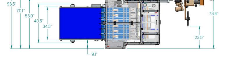
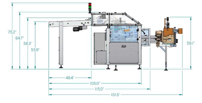
3 The control is assured by a state of the hart CIP motion controller. Equipped with ETHERNET communication. You can choose between two different set ups (left hand or right hand). The conveyor is equipped with a start and stop option to get tighter bags. The KWIK LOK machine can be adapted to this system. Dimensions and weight (for transport) Height: 72,2 inches Length: 91 inches Width: 93.5 inches Power for electricity and air data ELECTRICAL 220 VOLTS 15 AMPS 3 PH 60 HZ PNEUMATIC PSI Installation To be check before installation Check proper voltage before turn on the power on the machine Check if all legs are level and stable on the floor Make sure nothing else than bread product sitting on the belt Check for proper belt tracking Procedure for unpacking Remove all red marked screws from the wood box. Remove all lag bolt from the legs. With a fork lift gently lift the machine from underneath the frame. Move back with the fork lift drop the machine as low as possible as soon you are out from the wood box. Requirements for fixing/anchoring and vibration damping When proper location is find, proceed with levelling the legs Drill at least one ancrage per legs Minimum space required for use (men on the layout drawing) 2

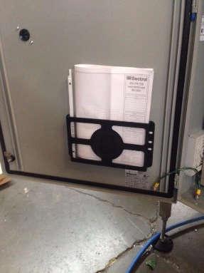
4 Location of the instructions Inside the control panel 3
5 OPERATION Training users, training courses are highly recommended given the complexity of the product, the indications to observe, the protection of persons and the instructions for the detection of faults. TROUBLE SHOOTING PROBLEM SYMPTOMS SOLUTIONS Machine won t Start 1- Emergency button depressed 2- One of the cover is still open 3- Drive Error 1. Pull off the emergency button, press reset and press start 2. When the sensor start flashing green, look at all the door sensor light. If one of them is red close the door related to the sensor. Press the reset button and press start 3. Open the electrical box. Look at error code on the drive and refer to page 112 of the Allen Bradley Kenetix 350 Manual for solution. Visit Allen Bradley Web site for PDF version : um002_-en-p.pdf 4
 3. Unscrew the set cap s screw on the head of the gear box 4.")
 7. Take off the motor 8. Fix the new motor on the support (4 bolts) 9.")
6 MAINTENANCE AND CLEANING Pusher Motor Replacement Instruction 1. Turn off the equipment and put a padlock on the electrical box 2. Unscrew the side outfeed cover (6 screws) 3. Unscrew the set cap s screw on the head of the gear box 4. Inside the gear box, loose the socket head cap screw 5. Disconnect the electricity on the motor (2 connections) 6. Unscrew the bolts of the motor s support (4) 7. Take off the motor 8. Fix the new motor on the support (4 bolts) 9. Reconnect the electricity 10. Inside the gear box, tight the socket head cap screw 5
7 11. Screw the set cap s screw on the head of the gear box 12. Put back the outfeed cover Rotary Motor Replacement Instruction 1. Turn off the equipment and put a padlock on the electrical box 2. Unscrew the front outfeed cover (6 screws) 3. Open the hood of the bagger 4. Unscrew the set cap s screw on the head of the gear box 5. Inside the gear box, loose the socket head cap screw 6. Disconnect the electricity on the motor (2 connections) + the cable s clamp (2 clamps) 7. Unscrew the bolts of the motor s support (1) 8. Take off the motor 9. Fix the new motor on the support (1 bolt) 6
8 10. Reconnect the electricity + and fix the cable with the cable s clamp. 11. Inside the gear box, tight the socket head cap screw 12. Screw the set cap s screw on the head of the gear box 13. Put back the outfeed cover Outfeed Motor 1. Turn off the equipment and put a padlock on electrical box 2. Disconnect the electricity on the motor (2 connections) + the cable s clamp (2 clamps) 3. Unscrew the bolts of the motor s support (4) 7
9 4. Take off the motor 5. Unscrew the Love Joy s junction on the shaft of the motor 6. Put the Love Joy s junction on the new motor 7. Fix the new motor on the support (4 bolts) 8. Reconnect the electricity + and fix the cable with the cable s clamp. 8
10 Dispatch Motor Instruction 1. Turn off the equipment and put a padlock on electrical box 2. Disconnect the electricity on the motor (2 connections) + the cable s clamp (6 clamps) 3. Unscrew the bolts of the motor s support (4) 4. Take off the motor 5. loose the set screw on the pinion gear 6. Take off the pinion gear 7. Put the pinion on the new motor 8. Tight the pinion gear 9. Fix the new motor on the support (4 bolts) 9

 5. Unscrew the 90 degrees electric connector (PE-00106) 6.")
11 10. Reconnect the electricity + and fix the cable with the cable s clamp. Conveyor Stopper Motor Replacement Instruction 1. Turn off the equipment and put a padlock on electrical box 2. Unscrew the cover of the motor s electrical box 3. Unscrew the electricity ground 4. Untwist the twist-on wire connection (3) 5. Unscrew the 90 degrees electric connector (PE-00106) 6. Loose the bolt of the motor s support (2) and push the motor forward to loose the belt. 10
 to fix the position 13. Put back the 90 degrees electric connector 14.")
12 7. Unscrew the bolts of the motor s support (4) 8. Take off the motor 9. Unscrew the timing pulley 10. Fix the Timing pulley on the new motor 11. Fix the new motor on the motor s support (4 bolts) 12. Tight the belt by pushing backward the motor support and tight the bolt (2) to fix the position 13. Put back the 90 degrees electric connector 14. Twist all the twist-on wire (Each wire s color have to be matched) 15. Put back the electric ground 16. Put back the cover of the motor electrical box N.B.: If the motor start turning in wrong direction, Untwist the blue and red wire in the electrical box and match the blue color and red color by twisting them together. 11
13 Conveyor Infeed Motor replacement Instruction 1. Turn off the equipment and put a padlock on the electrical box 2. Unscrew the belt cover guard (3 screws) 3. Unscrew the cover of the motor s electrical box 4. Unscrew the electricity ground 5. Untwist the twist-on wire connection (3) 6. Unscrew the 90 degrees electric connector (PE-00106) 7. Loose the bolt of the motor s support (5) and push the motor forward to loose the belt. 8. Unscrew the timing pulley 9. Unscrew the bolts of the motor s support (4) 10. Take off the motor 11. Fix the new motor on the motor s support (4 bolts) 12. Fix the Timing pulley on the new motor 13. Tight the belt by pushing backward the motor support and tight the bolt (3) to fix the position 14. Put back the 90 degrees electric connector 15. Twist all the twist-on wire (Each wire s color have to be matched) 16. Put back the electric ground 17. Put back the cover of the motor electrical box 18. Put back the belt guard N.B.: If the motor start turning in wrong direction, Untwist the blue and red wire in the electrical box and match the blue color and red color by twisting them together. 12
 and push the motor forward to loose the belt. 4. Put the new belt 5.")
14 BELTS Drive s Belt Infeed Instruction 1. Turn off the equipment and put a padlock on the electrical box 2. Unscrew the belt cover guard (3 screws) 3. Loose the bolt of the motor s support (5) and push the motor forward to loose the belt. 4. Put the new belt 5. Tight the belt by pushing backward the motor support and tight the bolt (3) to fix the position 6. Put back the belt guard Infeed belt Instruction 1. Turn off the equipment and put a padlock on electrical box 2. Take off the yellow junction 13


 Bottom Pusher Drive Belt Instruction 1.")
15 Top pusher drive belt Instruction 1. Turn off the equipment and put a padlock on electrical box 2. Loose the bearing bolt (2) 3. Push the bearing to loose the belt 4. Take off the belt 5. Put the new belt 6. Tight the belt by pushing the bearing in the opposite way. 7. Tight the bearing bolt (2) Bottom Pusher Drive Belt Instruction 1. Turn off the equipment and put a padlock on the electrical box 14
 of the drive s shaft support 7. Push the belt drive support forward to loose the belt tension 8. Take off the belt 9.")
 13. Fix the side outfeed cover Pusher Homing Sequence 1- On the screen, below the PUSHER title, press HOME to position the pusher.")
16 2. Unscrew the side outfeed cover (6 screws) 3. Disconnect the electricity on the motor (2 connections) 4. Unscrew the bolts of the motor s support (4) 5. Take off the motor support 6. Loose the bolt (2) of the drive s shaft support 7. Push the belt drive support forward to loose the belt tension 8. Take off the belt 9. Put a new belt and pull the belt drive support backward to tight the belt 10. Tight the bolt (2) of the drive shaft support to fix the position 11. Fix the motor s support (4) 12. Connect the electricity to the motor (2 connections) 13. Fix the side outfeed cover Pusher Homing Sequence 1- On the screen, below the PUSHER title, press HOME to position the pusher. 2- Verify if the indication is in the right position with the linear bearing. If not, you ll need to move the home sensor position. 3- Verify if the top pusher position match with the indication. If not, loose the bearing support and loose the tension of the belt. Make the belt jump a few teeth until you have a perfect match with the position. (see next page) 15


17 Rotary Homing Sequence 1- On the screen, below the Rotary title, press HOME. To position the Rotary 2- On the screen, change the value of the home position until the position match 3- To Align the Rotary bucket, loose the bolt of the timing pulley to align each bucket. See picture for right and wrong position Right Position Wrong position 16


18 The Chute assemblage 1. Unscrew the set cap s screw on the head of the gear box 2. Pull off the gear box 3. Unlock the slider s Chute (Yellow Lock) 17
19 4. Pull the chute out of the machine 5. To pull the Chute out of his support, lift the chute s frame to pull it out Product Corridor Adjustment 1- Turn off the equipment and put a padlock on the electrical box 2- Turn the black handle to adjust the width for the product size Stopper position adjustment 1- Turn off the equipment and put a padlock on the electrical box 2- Use the black handle to adjust the positon of the stopper, the top palm has to stop the second product to go in the chute 18
 Emergency button (1) Notice : The")


20 Safety and logo (Localization) Safety (7) Emergency button (1) Notice : The bag door table works in parallel with bag table. If the bag table is pulled out of position the equipment won t work. You can open the table s door during operation to reload the bag magazine without stopping the operation. 19


21 20
.")

22 Relay To work in junction with another equipment (ex: Rotary Slicer). Make sure to plug the relay cable to the relay input. If it s not plugged correctly the bagger won t work. 21


23 DANGER ZONE Make sure there s not space between the two equipment when system work in relay. Safety precautions Always put a padlock on the electrical box before processing to any operation of maintenance with the equipment We highly recommend to turn off and disconnect the equipment for all maintenance and cleaning. Pleased check that you have enough space to work and to open the equipment for maintenance. Any modification made on the equipment regarding, mechanical aspect, safety sensor, electricity, design or any part that are closely related to the equipment will avoid all guaranty and responsibility from KLR Systems. If a modification is required, please contact KLR Systems for approval. All technical manipulation has to be made by a qualified technician or a technician from KLR Systems. We re not responsible for any abuse, wrong manipulation, wrong utilization, wrong maintenance and reparation made by the owner, qualified technician and users. 22
24 DEFINITION: Danger : eventual source of injury or risk for the health. Danger Zone : All zone in or out of the equipment or in contact with the equipment. Person Exposed : All people that is in danger zone. Users : Person responsible to only operate the equipment with required training. Qualified personnel : Person who have received a training from KLR Systems for maintenance and possible issue related to the equipment. risk : possibility of potential event that can put in danger any person who are in the danger zone. Physical Safety : Physical part of the equipment made to reduce a risk of danger Safety device : Device (other than physical safety) made to reduce a risk of danger related or not with a physical safety. Normal use : operation of the equipment regarding the instruction Abuse, wrong utilization, wrong maintenance, wrong manipulation : operation of the equipment that are in contradiction with the instruction that can be related to a predicable human comportment Maintenance and cleaning by users. Recommendation: Safety: We recommend to blow air on each belt to avoid obstruction of the machine after each day of operation We recommended to call a qualified technician for any mechanical and electric issues All operation have to be made in a safe environment and proper condition to avoid any risk of damage on the equipment and for the safety of the users The Equipment have to be turned off to perform any maintenance and cleaning operation Regular Checks Before each utilization, please check if all belt are rolling in the proper direction and if there s no noise that come from the bearing. Contact a qualified technician for any maintenance regarding the bearing or the belt. If you see any suspicious problem that could damage the equipment or the safety of the user, please contact a qualified technical 23
25 Maintenance and cleaning by qualified personnel Recommendation: Safety: We recommend to blow air on each belt to avoid obstruction of the machine after each day of operation We recommended to refer to the manual or to a technician from KLR System for any mechanical and electric issues All operation have to be made in a safe environment and proper condition to avoid any risk of damage on the equipment and for the safety of the user The Equipment have to be turned off to perform any maintenance and cleaning operation Regular Checks Before each utilization, please check if all belt are rolling in the proper direction and if there s no noise that come from the bearing. Contact a qualified technician for any maintenance regarding the bearing or the belt. Each 3 month check all the bearing to make sure there s no noise and they can safely turn. Put some grease on it each 3 months. Use the proper grease (food grade grease). If you see any suspicious problem that could damage the equipment or could put in danger the safety of the user, please contact a technical from KLR Systems For any adjustment refer to the manual. For trouble shooting, refer to the drive manual (link in the trouble shooting section of the manual) or contact a technical from KLR Systems. MAINTENANCE AND REPERATIONS BY TECHNICIANS FROM KLR SYSTEMS INC. We recommend to contact a technician from KLR for any trouble shooting that can t be solve by qualified personnel. For all drive, programming and software issues, please call Addresses and contact information for service technicians Please call: Or at: info@klrsystems.com KLR SYSTEMS INC. 565 DESRANLEAU IS, SAINT-HYACINTHE, QC, CANADA J2T 2L 9 (450)
26 LISTS OF SPARE PARTS AND CONSUMABLES Annexed document DECOMMISSIONING OF THE PRODUCT It is advisable to plan a tour of KLR to reinstall the equipment after a prolonged deactivation or a move. 25
MANUAL - PNEUMATIC ACTUATORS, SERIES DA & SR - 1 -
 MANUAL - PNEUMATIC ACTUATORS, SERIES DA & SR - 1 - DOUBLE ACTING ACTUATOR DA SPRING RETURN ACTUATOR SR - LCIE 05 AR 022 MANUAL - PNEUMATIC ACTUATORS, SERIES DA & SR - 2 - Content 1. Applicable Range 3
Pneumatic actuator Assembly & maintenance procedures
 Pneumatic actuator Assembly & maintenance procedures SPRING RETURN ACTUATOR Fig.7901 DOUBLE ACTING ACTUATOR Fig.7902 - LCIE 05 AR 022 2 CONTENTS 1. Applicable Range... page 4-6 2. General Information...
PNEUMATIC ACTUATORS ASSEMBLY & MAINTENANCE PROCEDURES. Ref. Doc. MMMACTREGDRE English Rev.2 January 2012 ADA & ASR SERIES DOUBLE ACTING ACTUATOR ADA
 ADA & ASR SERIES SPRING RETURN ACTUATOR ASR DOUBLE ACTING ACTUATOR ADA - LCIE 05 AR 022 V R 1 REVIEW CONTROL PROCEDURE REF. DOC. MMMACTREGDRE Rev. Date Carried out by Approved Description 0 02-01-2006
450 Series Belt Driven Live Roller Curve Conveyor Installation and Maintenance Manual
 450 Series Belt Driven Live Roller Curve Conveyor Installation and Maintenance Manual Metzgar Conveyor Co. - 2010 METZGAR CONVEYORS SAFETY PRECAUTIONS WARNING: DO NOT ATTEMPT MAINTENANCE ON ANY CONVEYORS
Operating instructions ErgoPack 600 E
 Operating instructions ErgoPack 600 E Operation of the device is only permitted if the operating instructions have been carefully read and understood before use! Declaration of conformity EU declaration
FD 342 Document Folder
 FD 342 Document Folder 6/2010 OPERATOR MANUAL FIRST EDITION TABLE OF CONTENTS SUBJECT PAGE DESCRIPTION 1 SPECIFICATIONS 1 UNPACKING 2 SETUP 2 CONTROL PANEL 3 OPERATION 4 SETTING CUSTOM FOLDS 5 BATCH COUNTING
3000W HF/PFC Battery Charger
 3000W HF/PFC Battery Charger Description Advanced high frequency switching design with 92% typical efficiency Fully sealed enclosure providing improved reliability in demanding environments > 0.98 Power
Best Diversified Products, Inc. Product Manual. BestReach Rigid Belt. Models BRB 230 OS BRB 230 SS BRB 460 OS BRB 460 SS
 Best Diversified Products, Inc. Product Manual TM BestReach Rigid Belt Models BRB 230 OS BRB 230 SS BRB 460 OS BRB 460 SS Best Diversified Products Inc. 107 Flint Street Jonesboro, AR 72401 Phone 870-935-0970
User Manual GRX- 950 and GRX- 950 Li
 User Manual GRX- 950 and GRX- 950 Li Page 1 of 17 TABLE OF CONTENTS INTRODUCTION 3 BASIC SET- UP 4 TURNING ON YOUR GRX- 950 7 PRECAUTIONS 8 FREE WHEEL MODE 9 GENERAL BATTERY CARE 10 BATTERY INFORMATION
P44 Stepper. User Manual
 P44 Stepper User Manual Table of Contents Introduction 1 Safety Warning 2 Overview of Parts 2 Attaching to Chair 3 Manoeuvring Around 4 Setting Pedal Stops 4 Getting On 5 Setting the Resistance (models
Index. 1. Important safety instructions Overview of the lift Installation instructions Operation instructions 8-9
 2 Index 1. Important safety instructions 4-5 1.1 Safety Warnings 1.2 Qualified personnel 1.3 Safety 1.4 Warning signs 2. Overview of the lift 6 2.1 General descriptions 2.2 Technical data 2.3 Construction
MODEL SCA Installation and Operation Manual Important:
 MODEL SCA Installation and Operation Manual Important: This manual contains specific cautionary statements relative to worker safety. Read this manual thoroughly and follow as directed. It is impossible
BELT CONVEYOR PNL/4 Series User and maintenance manual
 BELT CONVEYOR PNL/4 Series User and maintenance manual 1 DECLARATION OF CONFORMITY CE In conformity with the 2006/42/CE Machine Directives, Enclosure II, section A The company: VIRGINIO NASTRI S.r.l. Tel.
ELECTRIC HOIST MODEL NO: CH2500B, CH4000B OPERATION & MAINTENANCE INSTRUCTIONS PART NO: , LS1010
 ELECTRIC HOIST MODEL NO: CH2500B, CH4000B PART NO: 7630386, 7630391 OPERATION & MAINTENANCE INSTRUCTIONS LS1010 INTRODUCTION Thank you for purchasing this CLARKE Electric Hoist. Before attempting to use
BELT CONVEYOR CB/M5 Series
 BELT CONVEYOR CB/M5 Series User and maintenance manual 1 DECLARATION OF CONFORMITY The company: Tel. +39-0444 450 620-451 520 Fax +39-0444 671 840 declares under its own responsibility that the machine
TABLE OF CONTENTS INSTALLATION & OPERATING INSTRUCTION MANUAL FOR MODEL PRC-- POWER ROLLER CONVEYOR
 TABLE OF CONTENTS INSTALLATION & OPERATING INSTRUCTION MANUAL FOR MODEL PRC-- POWER ROLLER CONVEYOR 1. INSTALLATION 2 1.1. GENERAL INSTALLATION 2 1.1.1. Building Connections 3 2. OPERATION 3 2.1. GENERAL
Remove 4 circled pins. Route wiring along dashed line. Remove the 2 9mm nuts and black retaining plate that secure extractor.
 2015 Ford Mustang Turn Signal Hood Kit Parts List: Quantity: Tool List: Bracket & pre-installed lamp 2 Flat head screwdriver Wiring harness 1 Phillips screwdriver PB-3660 Parts Bag 1 Ratchet & Socket set
Continuing Education Course #206 Introduction to Designing Machine Control Systems Part 2
 1 of 5 Continuing Education Course #206 Introduction to Designing Machine Control Systems Part 2 1. Continuing to answer the following questions indicates that you understands that the presented material
SMC BATTERY CHARGER USER S MANUAL SMC USER S MANUAL
 SMC BATTERY CHARGER SMC 1 INDEX 1 INDEX... 1 2 INTRODUCTION... 2 2.1 INTRODUCTION AND REFERENCES... 2 2.2 GLOSSARY... 2 2.3 DATA LABEL... 2 2.4 HOW TO USE THE USER'S MANUAL... 2 2.5 RESPONSIBILITY DISCLAIMER...
CRD610 Automatic Fitting Inserter
 CRD610 Automatic Fitting Inserter OPERATIONS MANUAL VERSION 1.2 LAST EDITED 12.12.2018 cleanroomdevices.com 1 Table of Contents Title Page. 1 Table of Contents...2 1.0 General Product & Safety Information....3
AUTOMATIC FOODSERVICE EQUIPMENT. AUTOMATIC ELECTRIC BROILER MODELS 824E & 850E and 624E & 650E. B-Series Broiler OWNER S MANUAL
 AUTOMATIC FOODSERVICE EQUIPMENT AUTOMATIC ELECTRIC BROILER MODELS 824E & 850E and 624E & 650E B-Series Broiler OWNER S MANUAL FOR YOUR SAFETY: Do not store or use gasoline or other flammable vapors or
CLEAN ROOM DEVICES, LLC "WHERE TUBING AND FITTINGS COME TOGETHER"
 CLEAN ROOM DEVICES, LLC "WHERE TUBING AND FITTINGS COME TOGETHER" CRD600 Automatic Fitting Inserter OPERATIONS MANUAL VERSION 2.1 LAST EDITED 7.25.14 DOCUMENT NUMBER 001 cleanroomdevices.com 1 Table of
XR Conveyor Maintenance Guide
 XR Conveyor Maintenance Guide EN-0035 Rev. A XR Conveyor Maintenance Guide www.qdraw.com Table of Contents 05/20/2009 Overview Page 3 XR Conveyor Assembly Page 4 General Information Exploded View of an
CRD600 Automatic Fitting Inserter
 CRD600 Automatic Fitting Inserter OPERATIONS MANUAL VERSION 2.3 LAST EDITED 12.07.2018 cleanroomdevices.com 1 Table of Contents Title Page.. 1 Table of Contents. 2 1.0 General Product & Safety Information...3
Assembly instructions PRORUNNER mk1 2
 Assembly instructions PRORUNNER mk1 Version 0.1 / 01-JUN-2013 Copyright Qimarox B.V. All rights reserved. No part of this document may be copied, stored in a database and/or published by means of printing,
ELECTRIC HOIST MODEL NO: CH2500B, CH4000B OPERATION & MAINTENANCE INSTRUCTIONS PART NO: ,
 ELECTRIC HOIST MODEL NO: CH2500B, CH4000B PART NO: 7630386, 7630391 OPERATION & MAINTENANCE INSTRUCTIONS ORIGINAL INSTRUCTIONS LS0517 - Iss 5 INTRODUCTION Thank you for selecting this Clarke Electric Hoist.
PFC W HF/PFC Battery Charger
 PFC 5000 5000W HF/PFC Battery Charger Description Advanced high frequency switching design with 92% typical efficiency Fully sealed enclosure providing improved reliability in demanding environments >
FULL OPERATING AND MAINTENANCE MANUAL
 Enter Serial No. here. In the event of an enquiry please quote this serial number. www.monoequip.com FULL OPERATING AND MAINTENANCE MANUAL FOR THE STAND ALONE DIVIDER FG398 Stand alone divider REV.A17
CLEAN ROOM DEVICES, LLC "WHERE TUBING AND FITTINGS COME TOGETHER"
 CLEAN ROOM DEVICES, LLC "WHERE TUBING AND FITTINGS COME TOGETHER" CRD600AF Automatic Fitting Inserter With Auto Feed OPERATIONS MANUAL (Shown with optional alcohol dispenser) 1 VERSION 1.1 LAST EDITED
RollSeal 1733 County Road 68 Bremen, Alabama Part No Rev Owner s Manual RS-Divider Curtain
 1. 2. 7 3. 4. RollSeal 1733 County Road 68 Bremen, Alabama 35033 256-287-7000 Part No 4801-5176 Rev 12-11-17 Owner s Manual RS-Divider Curtain Table of Contents 1 Warnings (Avertissements)... 3 2 Limited
Operations & Maintenance Manual DFH-1000 DUCTLESS FUME HOOD
 Operations & Maintenance Manual DFH-1000 DUCTLESS FUME HOOD ----------------------------------------------------------------We Make Clean Air----------------------------------------------------------------
AUTOMATIC SPINDLE CAPPER
 OPERATIONS MANUAL AUTOMATIC SPINDLE CAPPER (Shown above in one of several configurations.) 3999 East Hupp Road, Bldg. R-43 Phone: 219-393-3600 La Porte, IN 46350 Fax: 219-393-5260 www.liquidpackagingsolution.com
FOLDING DOOR ASSEMBLY AND MAINTENANCE MANUAL
 FOLDING DOOR ASSEMBLY AND MAINTENANCE MANUAL *ACMAP1* ACMAP1 INS-TEC-GC-40.02 V1 Rev.: 11.2005 INDEX PACKAGING CONTENT...3 TECHNICAL DRAWING...3 OPERATOR ASSEMBLY INTO THE CABIN DOOR...4 SILL ASSEMBLY...4
Title: Illustrated troubleshooting and set-up guide for Kinetrol EL Positioners
 INTRODUCTION These instructions are a supplement to the Kinetrol maintenance instructions TD76 / TD120 and explain how to check the EL units in case of failure including - Failure to move when signal and
Heavy duty slurry pumps
 USERS MANUAL Heavy duty slurry pumps TOYO PUMPS EUROPE Edition 27.07.2007 SAFETY INSTRUCTIONS TOYO PUMPS EUROPE Users manual for Toyo pumps type «DP..-6 30~40HP» This users manual will help you to maintain
Installation & Calibration Manual
 Installation & Calibration Manual SkidWeigh ED2-Print Series On-board Lift Truck Check Weighing Scale With Accumulative Load Total ED2-Print V1600 General Installation Guide This SkidWeigh ED2-Print system
RS4000 Setup. Before you install the RS4000 system, check to ensure that nothing was damaged or lost during shipping.
 RS4000 Setup Before you install the RS4000 system, check to ensure that nothing was damaged or lost during shipping. If anything is damaged or missing, contact your salesman immediately. Mount Components
PNL-MS Belt Conveyor with Metal Detector
 PNL-MS Belt Conveyor with Metal Detector Date: Apr, 2013 Version: Ver.B (English) Contents 1. General Description... 7 1.1 Coding Principle... 8 1.2 Features:... 8 1.2.1 Specifications Table... 10 1.2.2
GLO-502/530 (RIM CLAMP TIRE CHANGER)
") GLO-502/530 (RIM CLAMP TIRE CHANGER) OPERATION MANUAL DATE INSTALLED: SERIAL # MANUFACTURING DATE: (EAGLE - GLOBAL : NHT) TABLE OF CONTENT INTRODUCTION -------------------------------------------------------------------------------2
GLO-502/530 (RIM CLAMP TIRE CHANGER) OPERATION MANUAL DATE INSTALLED: SERIAL # MANUFACTURING DATE: (EAGLE - GLOBAL : NHT) TABLE OF CONTENT INTRODUCTION -------------------------------------------------------------------------------2
SARGON S - M - L. All rights reserved INSTALLATION MANUAL
 INSTALLATION MANUAL Our compliments for your excellent choice. SARGON LINE S (300mm) M (400mm) and L (600mm) electro-mechanical gear motor has been produced for reliability and high quality. This Manual
EB Conveyor Maintenance Guide
 EB Conveyor Maintenance Guide EN-0037 Rev A EB Conveyor Maintenance Guide www.qdraw.com Table of Contents Overview Page 3 Exploded View Of A Standard EB Conveyor Page 4 Preventative Maintenance Page 5
3 Phase Smart Controller
 3 Phase Smart Controller Installation and Owner s Manual STP-SCIII 208-230 VAC, 60Hz, 120 Volt Coil Franklin Fueling 3760 Marsh Rd. Madison WI 53718 USA Tel: +1 608 838 8786 800 225 9787 Fax: +1 608 838
Ford Mustang V6 OEM-Style Fog Light Kit Parts List: Quantity: Tool List:
 2015-2017 Ford Mustang V6 OEM-Style Fog Light Kit Parts List: Quantity: Tool List: LED Foglights/ Bezels 2 Flat head & Phillips screwdriver (if you ordered part#3600) Ratchet & Socket set OR Wiring harness
5th Wheel Electric Leveling System
 LEVELING SYSTEM MADE IN USA MADE IN U.S.A. R V PR ODUC T S NORCO INDUSTRIES, INC. 5th Wheel Electric Leveling System 20300513 TABLE OF CONTENTS...2 STANDARD PROCEDURES & AUTOMATED FUNCTIONS...3 UNIT DETACHMENT
OLYMPIAN MODEL 740 Operation and Service Manual
 OLYMPIAN MODEL 740 Operation and Service Manual P/N 133911-102 FCI MANUAL P/N 133865-001 Data herein has been verified and validated and believed adequate for the intended use. If the machine or procedures
MODEL 660 AUTOMATIC FASTENING CENTER OPERATOR S MANUAL
 MODEL 660 AUTOMATIC FASTENING CENTER OPERATOR S MANUAL Copyright: January 13, 2003 Revised: 080612 Serial No. 0506113. 1 TABLE OF CONTENTS INTRODUCTION..3 OPERATOR SAFETY... 3 SYSTEM REQUIREMENTS..4 INSTALLATION
Collector Drive for 44 Mower
 FORM NO. -80 Collector Drive for Mower Model No. 7955-990000 & Up Operator s Manual IMPORTANT: Read this manual, and your tractor manual, carefully. They contain information about your safety and the safety
We recommend installing the TRS Racebars first as we have done
 Thanks for purchasing the 2 Front Lowering Kit for the Honda Grom (MSX125). This is a basic installation guide, and we tried to cover everything, but use your best judgment along the process. It is recommended
Service Manual Gulf Stream Electronic Full Wall Slide Systems
 Service Manual Gulf Stream Electronic Full Wall Slide Systems CONTENTS Page Before you operate the slide system 2 Operating Instructions 3 Preventive maintenance 3 Manually overriding your slide system
INSTRUCTION MANUAL FOR MODEL PRC POWER ROLLER CONVEYOR
 INSTRUCTION MANUAL FOR MODEL PRC POWER ROLLER CONVEYOR - 1 - TABLEOFCONTENTS 1. OPERATION 3 1.1. GENERAL DESCRIPTION 3 1.2. OPERATION 3 1.2.1. GENERAL INSTRUCTIONS 3 2. MAINTENANCE 4 2.1. CHAIN TAKEUP
RolsplicerTM. Maintenance Manual And Illustrated Parts List
 RolsplicerTM Maintenance Manual And Illustrated Parts List List of Illustrations Figure Page. Rolsplicer 3 2. Roller Adjustment 4 3. Rolsplicer 6 4. Lid Hold Down Assembly 8 5. Automatic Lid Speed Adjustment
AUTOMATIC FOODSERVICE EQUIPMENT. AUTOMATIC ELECTRIC BROILER MODELS 952E, 932E and 922E OWNER S MANUAL
 AUTOMATIC FOODSERVICE EQUIPMENT AUTOMATIC ELECTRIC BROILER MODELS 952E, 932E and 922E OWNER S MANUAL IMPORTANT: RETAIN THIS MANUAL IN A SAFE PLACE FOR FUTURE REFERENCE. FOR YOUR SAFETY: Do not store or
Operation & Maintenance Manual
 Operation & Maintenance Manual Submersible pumps type LANDY DTP. Landustrie Sneek BV Tel. +31 515-486888 Pieter Zeemanstraat 6 Fax +31 515-412398 P. O. Box 199 info@landustrie.nl 8600 AD Sneek, Holland
ALUMAREEL. Electrical Cord Reel. Model EC6 100 Model EC Operational, Maintenance and Installation Manual
 ALUMAREEL TM Electrical Cord Reel Model EC6 100 Model EC3 100 Operational, Maintenance and Installation Manual READ AND UNDERSTAND THIS MANUAL BEFORE USING THIS PRODUCT. RETAIN FOR FUTURE REFERENCE 1 P
Installation Instructions Table of Contents
 Installation Instructions Table of Contents Pre- Installation of Garage Storage Lift 2 Layout the Garage Storage Lift 3 Installing the strut Channels 3 Install the Drive Assembly 5 Install the Drive Shaft
POWER PINNER RAPID FIRE 7005 RF OPERATOR S MANUAL
 POWER PINNER RAPID FIRE 7005 RF OPERATOR S MANUAL Copyright: February 20, 2007 Revised: 12-11-2015. Gripnail Corporation An Employee Owned Company 97 Dexter Road East Providence, Rhode Island 02914-2045
Maintenance manual XT modules
 Maintenance manual XT modules Copyright FlexLink 2013 The contents of this publication are the publishers and may not be reproduced (even extracts) unless permission is granted. Every care has been taken
FOUR POST LIFT STRONGMAN TOOLS. Manual to be used with only Strongman Tools Ltd 4 Post Lift
 FOUR POST LIFT STRONGMAN TOOLS Manual to be used with only Strongman Tools Ltd 4 Post Lift 2. SAFETY WARNINGS Thoroughly read this manual before operating the lift and comply with the instructions. Always
Safe-T-element Installation Instructions
 Safe-T-element Installation Instructions For: PTI STEZA (2x2 Burner Configuration) & PTI STEZB (3x1 Burner Configuration) Revision K (May. 3 2012) TABLE OF CONTENTS 1. PREPARATION... 3 1.1 General Safety
Collector Drive for 60 Mower
 FORM NO. -66 Collector Drive for 60 Mower Model No. 7965-990000 & Up Operator s Manual IMPORTANT: Read this manual, and your tractor manual, carefully. They contain information about your safety and the
Dry installed pump type LANDY BTP.
 OPERATION & MAINTENANCE MANUAL Dry installed pump type LANDY BTP. Landustrie Sneek BV Pieter Zeemanstraat 6 Tel. 0031 515-486888 P.O. BOX 199 Fax. 0031 515-412398 NL-8600 AD Sneek info@landustrie.nl The
Best/Flex ULTRA Gravity Conveyor
 Best/Flex ULTRA Gravity Conveyor Operation, Maintenance and Parts Manual Factory Order Number: Serial Number: Ship Date: BEST Conveyors 4929 Krueger Drive Jonesboro, AR 72401 800-327-9209 870-935-0970
HALOGEN FLOODLIGHTS Models CHL1260C & 1260T Part Nos: &
 HALOGEN FLOODLIGHTS Models CHL1260C & 1260T Part Nos: 5460600 & 5460595 OPERATING & MAINTENANCE INSTRUCTIONS GC0610 INTRODUCTION Thank you for purchasing this CLARKE Halogen Floodlight. Before attempting
IMPORTANT! DO NOT THROW AWAY THE SHIPPING CARTON AND PACKING MATERIAL
 Operator s Manual IMPORTANT! DO NOT THROW AWAY THE SHIPPING CARTON AND PACKING MATERIAL ii Table of Contents Operator Safety... 1 Introduction... 2 Unpacking and Setup... 3 Unpacking... 3 Setup... 4 ROCKET
Vetlab CombiSpin Centrifuge
 Vetlab CombiSpin Centrifuge User Manual 26.10.2017 Vetlab Supplies Ltd Unit 13 Broomers Hill Park Broomers Hill Lane Pulborough RH20 2RY Telephone: 01798 874567 Fax: 01798 874787 Email: info@vetlabsupplies.co.uk
Installation, Operation and Maintenance Manual. EVC Controller (from February 2007)
") Installation, Operation and Maintenance Manual (from February 2007) Publication 2698C (GB) 0207 1A 3319 8035B Donaldson reserve the right to alter design without notice. Freedom from patent restrictions
Installation, Operation and Maintenance Manual (from February 2007) Publication 2698C (GB) 0207 1A 3319 8035B Donaldson reserve the right to alter design without notice. Freedom from patent restrictions
Installation, Operation and Maintenance Manual
 HQ 005. ELECTRIC ACTUATORS QUARTER-TURN ELECTRIC ACTUATORS Installation, Operation and Maintenance Manual s Version Ver. 1 Revision Rev. 1 Document No. HKQI-611 Small & Compact Design High corrosion resistance
BAG FLATTENER CONVEYOR
 JEM INTERNATIONAL, INC. BAG FLATTENER CONVEYOR INSTALLATION & REPAIR MANUAL JEM INTERNATIONAL, INC. 6873 MARTINDALE SHAWNEE, KS 66218 Phone 913-441-4788 Fax 913-441-1711 JEMBAGGINGSCALES.COM DESCRIPTION
DYNAFLUID 2000 STEAM & WATER MIXING VALVE INSTALLATION & OPERATING MANUAL
 DYNAFLUID 2000 STEAM & WATER MIXING VALVE INSTALLATION & OPERATING MANUAL LILLY ENGINEERING COMPANY 217 CATALPA STREET P.O. BOX 173 ITASCA, ILLINOIS 60143 630-773-2222 FAX: 630-773-3443 www.lillyengineering.com
1329I Integrated Drive/Motor CE Filter Option Kit
 Instruction Sheet 1329I Integrated Drive/Motor CE Filter Option Kit CE filter options are designed to be used with the 1329I Integrated Drive/Motor. The main function of the CE filter is to reduce the
Side Seal Horizontal Shrink Wrapper
 ARPAC 9511 West River Street, Schiller Park, IL 60176 US Phone:847-678-9034 Fax:847-671-70 E-Mail: atillander@arpac.com Web site:www.arpac.com Item # ARPAC TS37, Side Seal Horizontal Shrink Wrapper QUOTE
2106 HDCT-DUAL Belt Tracker
 2106 HDCT-DUAL Belt Tracker Features Stainless steel construction Two cylinders for added tracking power and neutral positioning External bearings Two mechanical remote sensors Filter regulator unit Tracker
PRODUCT INFORMATION BULLETIN #3365 DIGITAL MOTOR CONTROL PLATTER SYSTEMS For Serial Number and After
 PRODUCT INFORMATION BULLETIN #3365 DIGITAL MOTOR CONTROL PLATTER SYSTEMS For Serial Number 28640996 and After Record Platter System Identification Numbers Here: Model # Serial # Table of Contents Program
Reliant Series Floor Scale
 Installation Manual Reliant Series Floor Scale Model: 3300 2005 by Fairbanks Scales. All rights reserved 50783 Issue 2 10/06 Amendment Record Reliant Series Floor Scale Model: 3300 50783 Manufactured by
P. D. Q. Automatic Burnout Furnaces. 115 and 230-volt Models OPERATOR S MANUAL
 P. D. Q. Automatic Burnout Furnaces 115 and 230-volt Models OPERATOR S MANUAL TABLE OF CONTENTS Introduction... 3 Warranty... 3 Safety Instructions........................................................
6500DC Dual Motor Wireless Controller Kits
 6500DC Dual Motor Wireless Controller Kits READ ALL DIRECTIONS FIRST BEFORE PROCEEDING NOTE: SEE THE QUICK PROGRAM INSTRUCTIONS BEFORE OPERATING THE FIRST TIME. DO NOT REMOVE THE TRANSMITTER BATTERY Please
INSTALLATION INSTRUCTIONS
 INSTALLATION INSTRUCTIONS "Elevate your storage needs to a Higher Level" MODEL # ASL-500 Aladdin Storage Lift, LLC. Aladdin 61 Shields StorageRoad Lift, LLC. Huntsville, AL 35811 Phone (256) 429-9700 Fax
INSTALLATION INSTRUCTIONS
 0711016 Page 1 INSTALLATION INSTRUCTIONS ELECTRONIC DEADBOLT WITH KEYPAD latch 2-3/8 Your latch is now set 2-3/8 (60mm) backset latch 2-3/4 2-3/4" (70mm) 2-3/8" (60mm) Cylindrical cover Extension plate
INSTRUCTION MANUAL_1219_ENGLISH SUPER ELF X3. Operating Instructions for DORNIER looms. Robustness Reliability Quality Productivity Versatility
 INSTRUCTION MANUAL_1219_ENGLISH SUPER ELF X3 Operating Instructions for DORNIER looms Robustness Reliability Quality Productivity Versatility WARNING! - Condensation could form on the Weft Feeder when
This is the Unpacking Guide for the Optibike Pioneer Allroad electric bicycle. The Guide provides information required to remove the Allroad from the
 This is the Unpacking Guide for the Optibike Pioneer Allroad electric bicycle. The Guide provides information required to remove the Allroad from the box and assemble it. If you have not assembled a bicycle
INSTALLATION INSTRUCTIONS South Highway 11 Westminster, SC Toll Free (888) (864) FAX (864)
 (864) FAX (864)") These instructions apply to the servicing of the Lift Technologies MaxiMizer Integral Sideshifters Cylinder Head. WARNING! Unless the steps in the following Installation Instructions are properly followed
These instructions apply to the servicing of the Lift Technologies MaxiMizer Integral Sideshifters Cylinder Head. WARNING! Unless the steps in the following Installation Instructions are properly followed
DOCUMENT TYPE = FITTING INSTRUCTIONS ORIGINAL LANGUAGE = ENGLISH. Maximum door weight = 40kg per leaf total system 80kg
 Evolve SIM Kit DOCUMENT TYPE = FITTING INSTRUCTIONS ORIGINAL LANGUAGE = ENGLISH 80kg Maximum door weight = 40kg per leaf total system 80kg Maximum door width 2 x 2mtr Track = 675-1058mm (Up to 2035 mm
Linear Commutated Meat Filler IMC-CMF100 INTERNATIONAL MACHINE CONCEPTS WELCOMES YOU TO YOUR NEW MACHINE
 Linear Commutated Meat Filler IMC-CMF100 INTERNATIONAL MACHINE CONCEPTS WELCOMES YOU TO YOUR NEW MACHINE Operation Manual: Date 2017. Version 1. Serial Number 1 CONTENTS Chapter 1 Machine Description 1.1
6 x 10 Belt Disc Sander
 6 x 10 Belt Disc Sander FOR HELP OR ADVISE ON THIS PRODUCT PLEASE CALL OUR CUSTOMER SERVICE HELP LINE : 01509 500400 THE MANUFACTURER RESERVES THE RIGHT TO ALTER THE DESIGN OR SPECIFICATION TO THIS PRODUCT
IBT Series Square Drive Torque Wrenches
 IBT Series Square Drive Torque Wrenches Operation and Maintenance Manual Model.75, 1, 3, 5, 8, 10, 20, 25, 35, 50 http://www.torsionx.com Use the IBT Series Square Drive Torque Wrenches Model.75, 1, 3,
INSTALLATION, OPERATION AND MAINTENANCE MANUAL WALL EXHAUST FANS BELT & DIRECT DRIVE XB, HV, HVA, ADD, DDS, DDP
 INSTALLATION, OPERATION AND MAINTENANCE MANUAL WALL EXHAUST FANS BELT & DIRECT DRIVE XB, HV, HVA, ADD, DDS, DDP The purpose of this manual is to aid in the proper installation and operation of the fans.
 Operation and Maintenance Manual Model.75,, 3, 5, 8, 0, 0, 5, 35, 50 http://www.torsionx.com Use the MaxDrv Series Square Drive Torque Wrench Model.75,, 3, 5, 8, 0, 0, 5, 35, 50 to install and remove threaded
750 Series Press Conveyor Installation and Maintenance Manual
 750 Series Press Conveyor Installation and Maintenance Manual Metzgar Conveyor Co. - 2010 METZGAR CONVEYORS SAFETY PRECAUTIONS WARNING: DO NOT ATTEMPT MAINTENANCE ON ANY CONVEYORS WHILE IN OPERATION. BEFORE
3-PHASE SMART CONTROLLER STP-SCIIIC INSTALLATION GUIDE
 3-PHASE SMART CONTROLLER STP-SCIIIC INSTALLATION GUIDE The information in this publication is provided for reference only. While every effort has been made to ensure the reliability and accuracy of the
MOTOR CITY ROCKERZ INSTALLATION MANUAL Part # ROCKRHYD[... ] ROCKRELE[... ] (ALL COLORS)
![MOTOR CITY ROCKERZ INSTALLATION MANUAL Part # ROCKRHYD[... ] ROCKRELE[... ] (ALL COLORS)](/thumbs/89/99803499.jpg "MOTOR CITY ROCKERZ INSTALLATION MANUAL Part # ROCKRHYD[... ] ROCKRELE[... ] (ALL COLORS)") MOTOR CITY ROCKERZ INSTALLATION MANUAL Part # ROCKRHYD[....... ] ROCKRELE[....... ] (ALL COLORS) TABLE OF CONTENTS Equipment Specifications Page: 1 Equipment Features Page: 1 Suggested Tools and Installation
MOTOR CITY ROCKERZ INSTALLATION MANUAL Part # ROCKRHYD[....... ] ROCKRELE[....... ] (ALL COLORS) TABLE OF CONTENTS Equipment Specifications Page: 1 Equipment Features Page: 1 Suggested Tools and Installation
WEIGH SYSTEM WS 1 kg M CD with Weighing Electronics Unit EWK 3010 / 3015 TS
 GENERAL DESCRIPTION The WS 1 kg M CD weigh system, with its integrated infeed and outfeed belts, forms, in conjunctions with a type EWK 3010 or EWK 3015 TS weighing electronics unit, a high-performance
Operation Guide. Operation Guide. Winnebago Hydraulic Leveling Systems by Kwikee. Introduction. Table of Content WARNINGS
 Operation Guide 05/07 Kwikee #1422192 Rev. 0F Table of Content Page Introduction 1 Safety Information 1 Operation 2 Control Panel 3 Manual Leveling 3 Automatic Leveling 3 Remote Operation 4 Stabilizing
RENA AF371Feeder Operating Manual. Feeder. Operating Manual. Manual Part #: M AF371 Operations Rev
 Manual Part #: M-3022 Feeder AF371 Operations Rev. 3-16-04 1 RENA AF371 Feeder YOUR RENA AF371 IS DISTRIBUTED BY RENA SYSTEMS INC. SERVICE AND SUPPORT FOR THIS PRODUCT IS PROVIDED BY YOUR RENA DEALER.
60 Series Engine Controls
 ECU 60 Series Engine Controls Use CAUTION since you are applying 120VAC RMS to the AC Input terminals and that it is always potentially their during engine run!!! ECU is a registered trademark of Engineering
INSTALLATION, OPERATION AND MAINTENANCE MANUAL WALL EXHAUST FANS BELT DRIVE XBL FANS
 INSTALLATION, OPERATION AND MAINTENANCE MANUAL WALL EXHAUST FANS BELT DRIVE XBL FANS The purpose of this manual is to aid in the proper installation and operation of the fans. These instructions are intended
TCM & MAT Data Logger Battery Replacement Instructions
 TCM & MAT Data Logger Battery Replacement Instructions These instructions apply to the following products: MAT-1 Data Logger TCM-1 Current Meter TCM-2 Wave and Current Meter TCM-3 4500m Current Meter The
Automatic Burnout Furnaces 115 to 230-volt Models OPERATOR S MANUAL
 Automatic Burnout Furnaces 115 to 230-volt Models OPERATOR S MANUAL TABLE OF CONTENTS Introduction...3 Warranty...3 On-Line Warranty Registration...3 Safety Instructions........................................................3
HGS SYSTEM Workshop Manual M103 01
 HGS SYSTEM Workshop Manual M0 0 HGS SYSTEM VERSION.0 EN/0-00 Autobusfabriek BOVA b.v. De Vest 9 5555 XL Valkenswaard The Netherlands Phone: + (0) 40 0846 Fax: + (0) 40 09477 E-mail: basis@bova.nl Website:
TA-05/C. Instruction and Operation Manual. valid for art.-no.: F-TA-05/C-ISO. (start at modification No. 1601)
") Instruction and Operation Manual valid for art.-no.: 10091 F-TA-05/C-ISO (start at modification No. 1601) valid for art.-no.: 10092 F-TA-05/C-Sh (start at modification No. 1601) CAUTION: As with any form
Instruction and Operation Manual valid for art.-no.: 10091 F-TA-05/C-ISO (start at modification No. 1601) valid for art.-no.: 10092 F-TA-05/C-Sh (start at modification No. 1601) CAUTION: As with any form
Roller Door Operator
 INSTALLATION INSTRUCTIONS AND OWNERS MANUAL Roller Door Operator IMPORTANT PLEASE READ THESE INSTRUCTIONS CAREFULLY PRIOR TO COMMENCING THE INSTALLATION OF THE OPERATOR UNIT CAUTION This Automatic Opener