ENGINE GENERAL ENGINE GENERAL GENERAL OVERVIEW AND OPERATION PROCESS 1. STRUCTURE...
|
|
|
- Tracey Owen
- 5 years ago
- Views:
Transcription
1 GENERAL 1. STRUCTURE... 3 OVERVIEW AND OPERATION PROCESS 1. ENGINE CONTROLS COMPONENTS INTAKE SYSTEM COMPONENTS EXHAUST SYSTEM COMPONENTS LUBRICATION SYSTEM COMPONENTS COOLING SYSTEM COMPONENTS FUEL SYSTEM COMPONENTS
2

 13. Oil filter 14. Vacuum pump 15. Crank position sensor 16. EGR valve 17.")
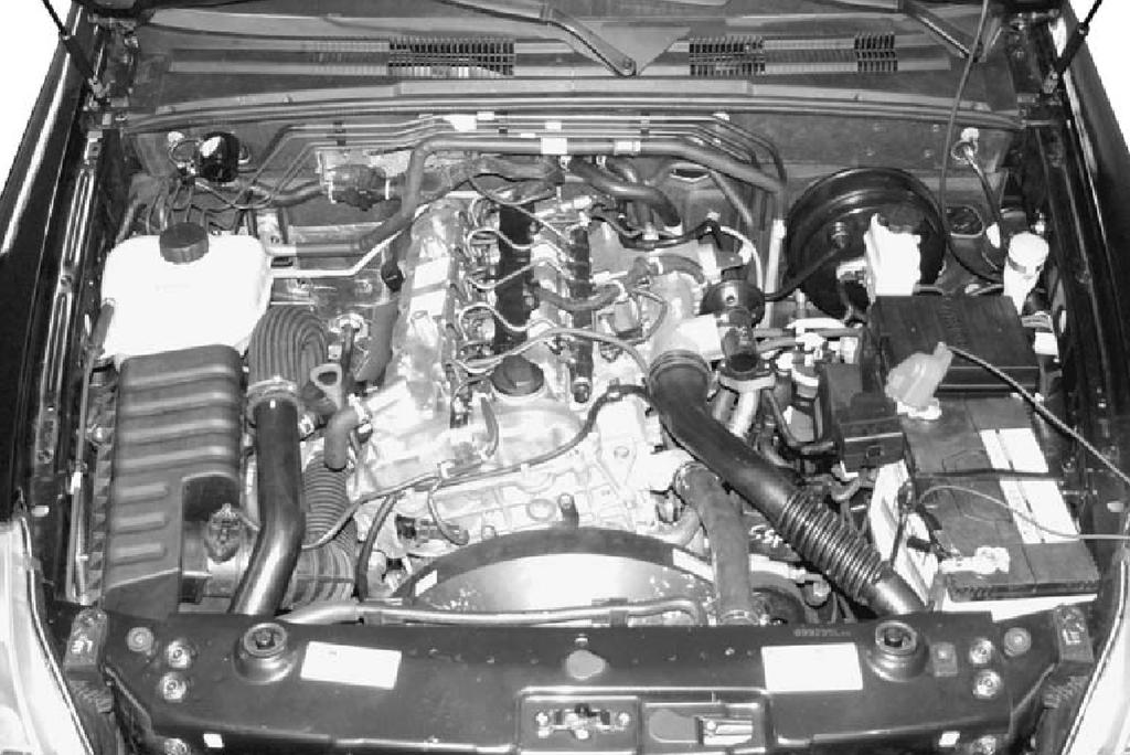
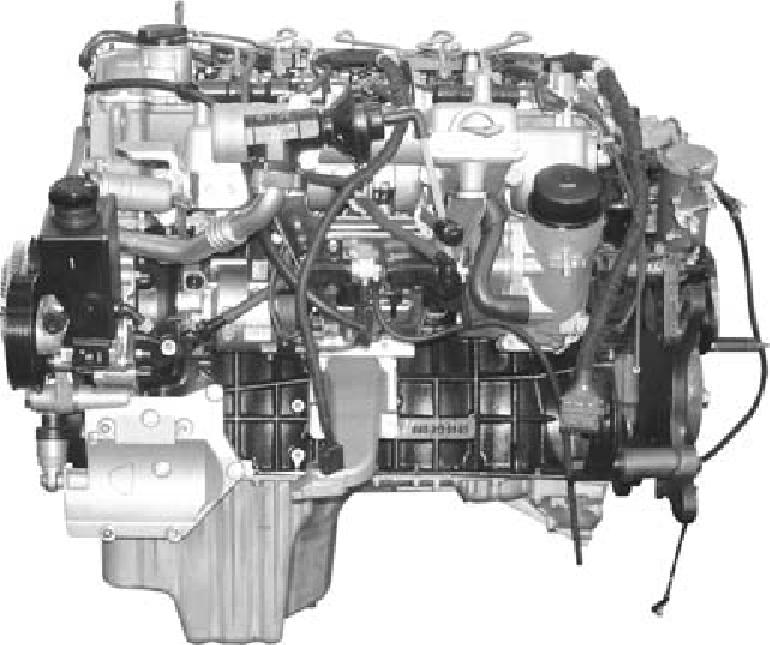
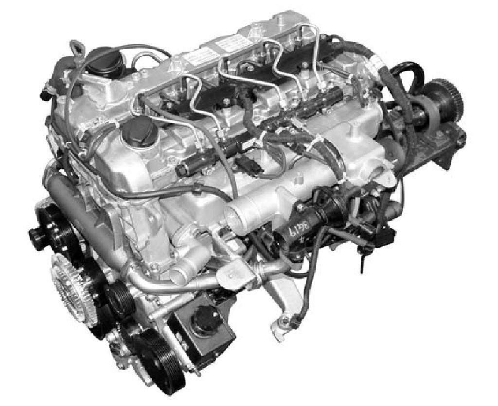
3 01-3 GENERAL 1. STRUCTURE Front view Rear view 1. TVD (Torsional Vibration 2. Damper) 3. Air conditioner compressor 4. Power steering pump pulley 5. Idle pulley 6. Water pump pulley Alternator 7. Cooling fan pulley 8. Aut tensioner pulley 9. Auto tensioner 10. Poly-groove belt 11. Cam position sensor 12. Drive plate (M/T: DMF) 13. Oil filter 14. Vacuum pump 15. Crank position sensor 16. EGR valve 17. Power steering pump 18. EGR center pipe

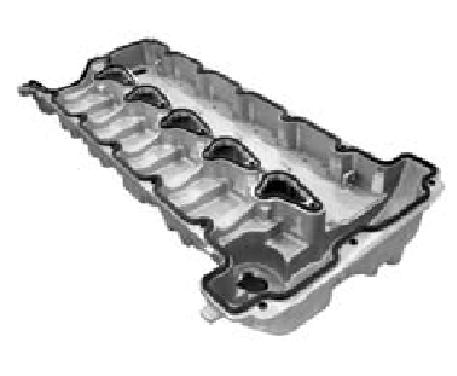
4 01-4 Top view 19. Cylinder head cover 20. Intake manifold 21. Water outlet port 22. Common rail 23. Fuel pressure sensor 24. Fuel pipe 25. Injector 26. Fuel return line 27. Oil filler cap 28. Glow plug 29. Booster pressure sensor 30. Oil separator 31. Oil dipstic 32. EGR center pipe

5 01-5 Left side view Right side view 33. Cylinder head 34. Cylinder block 35. pan 36. Drain plug 37. Turbocharger 38. EGR - RH (#3) pipe 39. Oil separator 40. Oil dipstic 41. HP pump 42. Turbocharger vacuum modulator 43. EGR valve vacuum modulator 44. EGR valve 45. Exhaust manifold


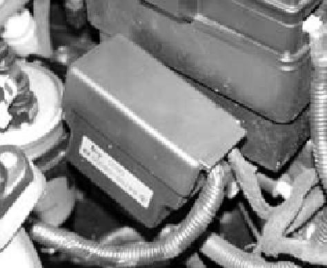
6 01-6 OVERVIEW AND OPERATION PROCESS 1. ENGINE CONTROLS COMPONENTS 1) ECU Related Components

7 01-7 2) Engine And Sensors
8 01-8 3) Electrical Components And Pre Heating System

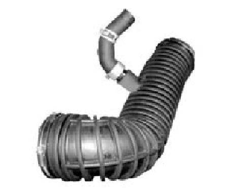
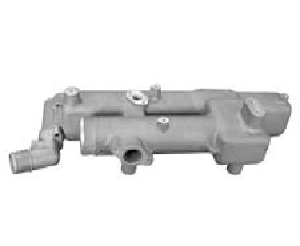
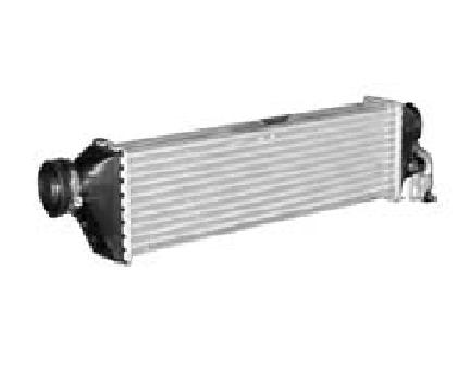
9 INTAKE SYSTEM COMPONENTS
10 01-10 Intake Air Flow Chart

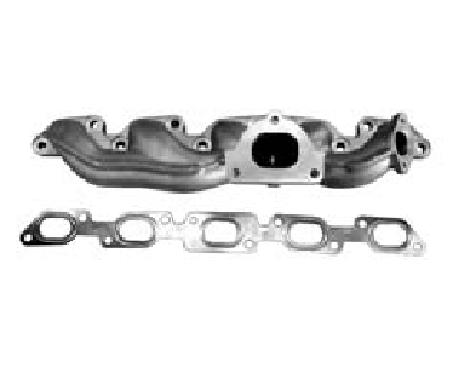
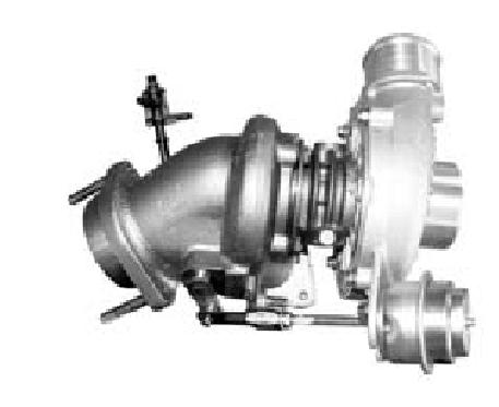
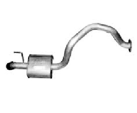
11 EXHAUST SYSTEM COMPONENTS
12 01-12 Exhaust Air Flow Chart
13 LUBRICATION SYSTEM COMPONENTS
14 01-14 Lubrication Flow Chart 1. Oil pump 2. Oil gallery (to oil filter) 3. Oil filter 4. Oil pressure switch 5. Main oil gallery 7. Oil gallery (chain tensioner side) 9. Chain tensioner 10. Vent (chain tensioner) 11. Front closing cover (φ 17 mm) 12. Oil gallery (at a right angle to axial direction) 13. Ball (φ 6 mm) 14. Oil spray nozzle (timing chain) 15. Oil gallery (cylinder head side) 16. Ball (φ 15 mm) 17. Oil restriction (inner - φ 4 mm) 18. Oil supply (to exhaust camshaft) 19. Oil supply (to intake camshaft) 20. Oil supply (to exhaust camshaft bearing) 21. Oil supply (to intake camshaft bearing) 22. Oil gallery (to exhaust valve tappet) 23. Oil gallery (to intake valve tappet) 24. Oil gallery (to chain tensioner) 25. Expansion plug 26. Ball 30. Valve tappet a. Oil gallery (between oil pump and oil filter) b. Main oil gallery c. Oil return line (the oil is returned to oil pan side when replacing filter element)

15 COOLING SYSTEM COMPONENTS
16 01-16 Coolant Flow Chart

17 FUEL SYSTEM COMPONENTS
 and then controls overall operating")

 sensor and camshaft speed (position)")


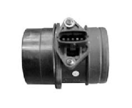
18 01-18 Fuel Supply System According to input signals from various sensors, engine ECU calculates driver's demand (position of the accelerator pedal) and then controls overall operating performance of engine and vehicle on that time. ECU receives signals from sensors via data line and then performs effective engine air-fuel ratio controls based on those signals. Engine speed is measured by crankshaft speed (position) sensor and camshaft speed (position) sensor determines injection order and ECU detects driver's pedal position (driver's demand) through electrical signal that is generated by variable resistance changes in accelerator pedal sensor. Air flow (hot film) sensor detects intake air volume and sends the signals to ECU. Especially, the engine ECU controls the air-fuel ratio by recognizing instant air volume changes from air flow sensor to decrease the emissions (EGR valve control). Furthermore, ECU uses signals from coolant temperature sensor and air temperature sensor, booster pressure sensor and barometric sensor as compensation signal to respond to injection starting, pilot injection set values, various operations and variables.
FUEL SYSTEM FUEL INJECTION SYSTEM. Electronic Control of Fuel System
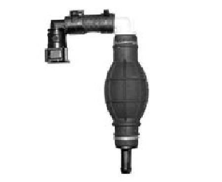
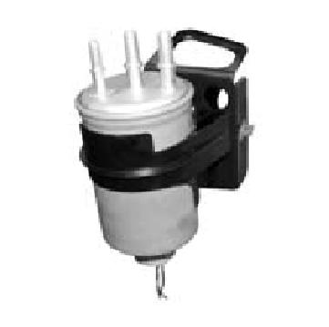
 07 5 FUEL INJECTION SYSTEM Electronic Control of Fuel System IMV valve Low and high pressure pump Fuel temperature sensor High pressure pump Water separator Water detection sensor Fuel filter System composition
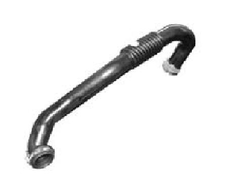
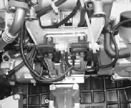
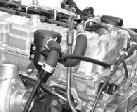
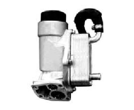
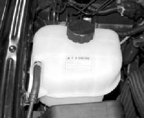
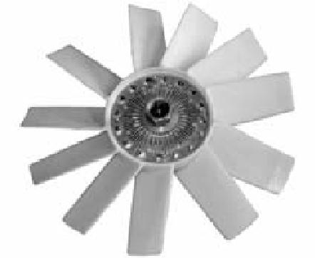
ENGINE ACCESSORIES. D20DT Engine. PCV valve and oil separator. Turbo charger. EGR pipe (LH, Center, RH) Cooling fan clutch. Auto tensioner.
 Cooling fan clutch. Auto tensioner.") 01 41 ENGINE ACCESSORIES Engine GENERAL PCV valve and oil separator Turbo charger Power steering pump Fuel return hose Alternator EGR pipe (LH, Center, RH) Cooling fan clutch EGR valve Auto tensioner Cable
01 41 ENGINE ACCESSORIES Engine GENERAL PCV valve and oil separator Turbo charger Power steering pump Fuel return hose Alternator EGR pipe (LH, Center, RH) Cooling fan clutch EGR valve Auto tensioner Cable
DIESEL ENGINE MECHANICAL
 SECTION 1B3 DIESEL ENGINE MECHANICAL CAUTION: Disconnect the negative battery cable before removing or installing any electrical unit or when a tool or equipment could easily come in contact with exposed
DISASSEMBLY AND REASSEMBLY
 24 01 DISASSEMBLY AND REASSEMBLY COMPONENTS AND SPECIAL TOOLS Injector Puller Y99220072B Glow Plug Wrench Y99220132B Fuel Pipe Wrench Sealing Caps 665 995 5844 Injector Copper Washer Puller Y99220022B
Torque Guidelines (Z 22 SE)
") Page 1 of 14 Torque Guidelines (Z 22 SE) No. Designation Nm 1 Retaining bolts, coolant pump sprocket to coolant pump 2 Retaining bolts, balancer shaft timing chain guide rail to 3 Retaining bolts, balancer
Page 1 of 14 Torque Guidelines (Z 22 SE) No. Designation Nm 1 Retaining bolts, coolant pump sprocket to coolant pump 2 Retaining bolts, balancer shaft timing chain guide rail to 3 Retaining bolts, balancer
Fastener Tightening Specifications Specification
 2008 G6 Applies to: 3.5L Report a problem with this article Fastener Tightening s A/C Compressor Bracket Bolt Camshaft Position Actuator Assembly Bolt 16 Y 12 lb ft Camshaft Position Actuator Magnet Bolt
PARTIAL ENGINE ASSY (2ZZ GE)
") COMPONENTS 14189 140R701 7.0 (71, 62 in. lbf) Cylinder Head Cover No. 2 19 (194, 14) Radiator Support Upper 19 (194, 14) Radiator Hose Inlet Cruise Control Actuator Assy 6.0 (61, 53 in. lbf) Radiator Assy
COMPONENTS 14189 140R701 7.0 (71, 62 in. lbf) Cylinder Head Cover No. 2 19 (194, 14) Radiator Support Upper 19 (194, 14) Radiator Hose Inlet Cruise Control Actuator Assy 6.0 (61, 53 in. lbf) Radiator Assy
PARTIAL ENGINE ASSY COMPONENTS. Clip. Radiator Grille. Clip. Front Bumper Cover. Engine Under Cover LH. N m (kgf cm, ft lbf) : Specified torque
 : Specified torque") ENGINE MECHANICAL 1417 COMPONENTS 141FP01 Radiator Grille Front Bumper Cover Engine Under Cover RH Engine Under Cover LH A79361 962 1418 ENGINE MECHANICAL Heater Outlet Water Hose 7.0 (71, 62 in. lbf)
ENGINE MECHANICAL 1417 COMPONENTS 141FP01 Radiator Grille Front Bumper Cover Engine Under Cover RH Engine Under Cover LH A79361 962 1418 ENGINE MECHANICAL Heater Outlet Water Hose 7.0 (71, 62 in. lbf)
2003 Taurus/Sable Workshop Manual
 Page 1 of 24 SECTION 303-01A: Engine 3.0L (2V) ASSEMBLY 2003 Taurus/Sable Workshop Manual Engine Special Tool(s) Piston Ring Compressor 303- D032 (D81L-6002-C) Camshaft Bearing Set 303-017 (T65L-6250-A)
HIGH FUEL PRESSURE LINE
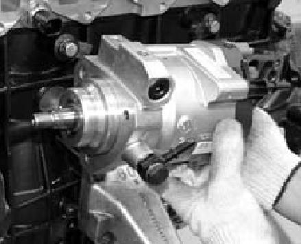
 16 07 HIGH FUEL PRESSURE LINE High Pressure Pump Description This pump generates high fuel pressure and is driven by timing chain (radial plunger principle). This pump pressurizes the fuel to approx. 1600
2000 Nissan Altima SE
 Removal 1. Release fuel pressure. See FUEL PRESSURE RELEASE. Drain coolant from radiator and cylinder block. Drain engine oil. Disconnect all necessary coolant hoses, electrical connectors, vacuum hoses,
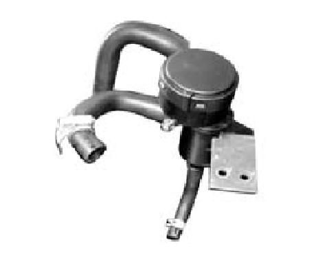
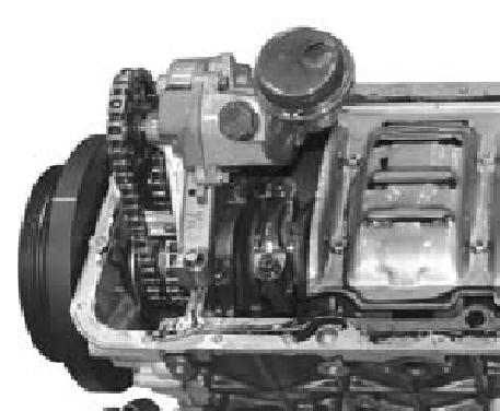
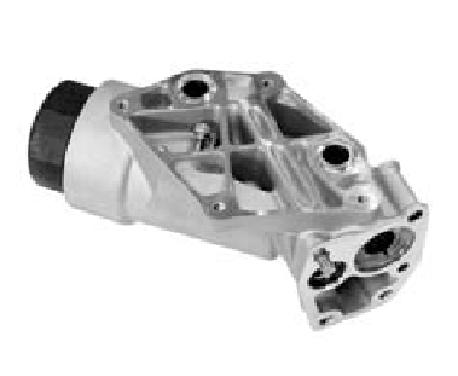
gas passes through baffle plates in cylinder oil separator inlet port. Separated oil returns The first separation will happen when blowby
 2 05 LAYOUT AND OVERVIEW Lubrication System PCV Oil Separator Cylinder head cover (oil + gas) Blow-by gas (air duct hose) Inlet port Oil (oil gauge pipe) The first separation will happen when blowby gas
PARTS MANUAL SUPPORTED BY HUSTLER TURF EQUIPMENT AND EXCEL INDUSTRIES, INC.
 SHIBAURA DIESEL ENGINE MODEL: N843 and N843L PARTS MANUAL SUPPORTED BY HUSTLER TURF EQUIPMENT AND EXCEL INDUSTRIES, INC. Table of Contents Chapter 1 General Information....................................
Intake Components 1117
 Item Part Number Description 1 W705654 Bolt 2 N807309 Bolt (2 req'd) 3 9F460 Bracket 4 N807071 Bolt (5 req'd) 5 9A448 Intake manifold (upper) 6 9E498 Vacuum harness 7 9F792 Fuel injection supply manifold
PARTIAL ENGINE ASSY (2TR FE)
") COMPONENTS 147 1421Z01 Clip Hood Subassy x9 Radiator Support to Frame Seal LH 30 (306, 22) 30 (306, 22) Fan and Generator V Belt 5.0 (51, 44 in. lbf) Fan Shroud Fan Pulley Fan w/ Fluid Coupling PRE RUNNER
COMPONENTS 147 1421Z01 Clip Hood Subassy x9 Radiator Support to Frame Seal LH 30 (306, 22) 30 (306, 22) Fan and Generator V Belt 5.0 (51, 44 in. lbf) Fan Shroud Fan Pulley Fan w/ Fluid Coupling PRE RUNNER
MINIMUM DRIVE PULSE (MDP) LEARNING
 LEARNING") 23 MINIMUM DRIVE PULSE (MDP) LEARNING When the pulse value that the injector starts injection is measured, it is called mininum drive pulse (MDP). Through MDP controls, can correct pilot injections effectively.
23 MINIMUM DRIVE PULSE (MDP) LEARNING When the pulse value that the injector starts injection is measured, it is called mininum drive pulse (MDP). Through MDP controls, can correct pilot injections effectively.
SECTION D Engine 6.0L Diesel
 303-01D-i Engine 6.0L Diesel 303-01D-i SECTION 303-01D Engine 6.0L Diesel CONTENTS PAGE DESCRIPTION AND OPERATION Engine... 303-01D-2 303-01D-2 Engine 6.0L Diesel 303-01D-2 DESCRIPTION AND OPERATION Engine
M162 ENGINE MECHANICAL
 SECTION 1B1 M162 ENGINE MECHANICAL CAUTION: Disconnect the negative battery cable before removing or installing any electrical unit or when a tool or equipment could easily come in contact with exposed
NOTE: Do not disassemble upper intake manifold from lower intake manifold unless replacement of one of the components is necessary.
 Fig. 2: Lower Intake Manifold Bolt Tightening Sequence INTAKE MANIFOLD (UPPER) NOTE: Do not disassemble upper intake manifold from lower intake manifold unless replacement of one of the components is necessary.
Intake Manifold: Service and Repair Removal
 1992 Toyota Truck Pickup 2WD V6-180.5 2959cc 3.0L SOHC (3VZ-E) Copyright 2013, ALLDATA 10.52 Page 1 Intake Manifold: Service and Repair Removal NOTE: If removing and later reinstalling the fluid coupling
 Page 1 of 9 303-01C Engine 6.0L Diesel 2004 F-Super Duty 250-550/Excursion DESCRIPTION AND OPERATION Procedure revision date: 08/06/2003 Engine Printable View Engine Description The 6.0L diesel engine
1999 Nissan Altima GLE
 TIMING CHAIN CAUTION: If cylinder head is installed and timing chain is disconnected, DO NOT rotate camshaft or crankshaft; valves will contact pistons, resulting in bent valves. NOTE: Following procedure
Section 10 Chapter 6
 Section 10 Chapter 6 24 Valve, 8.3 Liter Engine Identification Note: All coding used in the 8.3 Liter and 9 Liter engine manuals are Cummins engine codes. These engine codes have no meaning to New Holland
1991 Nissan 240SX. 2.4L 4-CYL - VINS [F,M,S] 1991 ENGINES Nissan 2.4L 4-Cylinder
![1991 Nissan 240SX. 2.4L 4-CYL - VINS [F,M,S] 1991 ENGINES Nissan 2.4L 4-Cylinder](/thumbs/95/123571962.jpg "1991 Nissan 240SX. 2.4L 4-CYL - VINS [F,M,S] 1991 ENGINES Nissan 2.4L 4-Cylinder") NOTE: Use illustration for component reference. See Fig. 7. 1. Remove spark plug wires. Set No. 1 piston at TDC on its compression stroke. Remove vacuum hoses, electrical harnesses, connectors, and harness
NOTE: Use illustration for component reference. See Fig. 7. 1. Remove spark plug wires. Set No. 1 piston at TDC on its compression stroke. Remove vacuum hoses, electrical harnesses, connectors, and harness
COMPONENT LOCATOR > DISASSEMBLED VIEWS
 Page 1 of 45 2006 Pontiac Grand Prix 3.8L Eng Base Service Manual: ENGINE MECHANICAL - 3.8L COMPONENT LOCATOR > DISASSEMBLED VIEWS Fig 1: Engine Block Component Views Callout Component Name 100 Engine
2000 Econoline Workshop Manual. 3. Install the upper intake manifold. 2. NOTE: Tighten the bolts in two stages.
 2. NOTE: Tighten the bolts in two stages. Tighten the bolts in the sequence shown. Stage 1: Tighten to 2 Nm (18 lb-in). Stage 2: Tighten to 10 Nm (89 lb-in). 3. Install the upper intake manifold. Position
SERVICING SPECIFICATIONS (1) ENGINE BODY
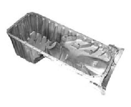
 ENGINE BODY") SERVICING SPECIFICATIONS (1) ENGINE BODY Lubricating oil capacity Oil pan depth 110 mm (4.33 in.) 5.7 L 1.5 U.S.gals (1/14) Oil pan depth 125 mm (4.92 in.) 5.1 L 1.3 U.S.gals Oil pan depth 130 mm (5.12
SERVICING SPECIFICATIONS (1) ENGINE BODY Lubricating oil capacity Oil pan depth 110 mm (4.33 in.) 5.7 L 1.5 U.S.gals (1/14) Oil pan depth 125 mm (4.92 in.) 5.1 L 1.3 U.S.gals Oil pan depth 130 mm (5.12
Liugong Parts Part number Name Description
 Liugong Parts Part number Name Description 03A1022 drain plug 10A2892 gasket T2 10A4427 adjusting washer Q195 10A5633 washer ST12 10A7119 adjusting washer Q195 10A7120 adjusting washer Q195 10A7121 adjusting
CAMSHAFT ASSEMBLY. Preceding Work: Removal of cylinder head cover. Intake Camshaft and Exhaust Camshaft. Finger Follower and HLA. Camshaft Sprockets
 24 02 CAMSHAFT ASSEMBLY Preceding Work: Removal of cylinder head cover Finger Follower and HLA Intake Camshaft and Exhaust Camshaft D20DT Camshaft Sprockets D27DT D20DT D27DT Camshaft Position Sensor Cylinder
2005 Escape Workshop Manual Cylinder block
 22 6010 Cylinder block Cylinder Head Item Part Number Description 1 12A366 Coil-on-plug assembly (4 req'd) 2 6M293 Valve cover 3 12K073 Camshaft position (CMP) sensor 4 6766 Oil filler cap 5 6M293 Valve
Diesel Technology: Engines
 Diesel Technology: Engines NATEF Crosswalk The following NATEF Diesel Engines tasks (rev. 2004) are covered in this publication. The chart shows where each task is located within the publication. The first
2002 Explorer Sport/Sport Trac Workshop Manual
 Page 1 of 17 SECTION 303-01: Engine 4.0L Single Overhead Camshaft (SOHC) IN-VEHICLE REPAIR Procedure revision date: 07/13/2005 Cylinder Head Special Tool(s) Spark Plug Wire Remover 303-106 (T74P-6666-A)
SECTION A Engine 3.7L
 303-01A-i Engine 3.7L 303-01A-i SECTION 303-01A Engine 3.7L CONTENTS PAGE DESCRIPTION AND OPERATION Engine... 303-01A-2 Engine Identification... 303-01A-2 Engine Code Information Label... 303-01A-2 Engine
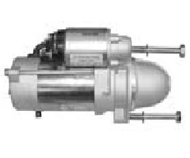
STARTER COMPONENTS FOR REMOVAL AND INSTALLATION
 Removal STARTER COMPONENTS FOR REMOVAL AND INSTALLATION Starter Components For Removal And Installation REMOVAL OF STARTER 1. DISCONNECT CABLE FROM NEGATIVE TERMINAL OF BATTERY CAUTION: Work must be started
CYLINDER HEAD (for Bank 2 4WD and Pre-Runner)
") 144 1GR-FE ENGINE MECHANICAL CYLINDER HEAD (for Bank 2 4WD and Pre-Runner) CYLINDER HEAD (for Bank 2 4WD and Pre-Runner) ENGINE 1GR-FE ENGINE MECHANICAL COMPONENTS 88 (897, 65) x4 88 (897, 65) x4 NO. 1
144 1GR-FE ENGINE MECHANICAL CYLINDER HEAD (for Bank 2 4WD and Pre-Runner) CYLINDER HEAD (for Bank 2 4WD and Pre-Runner) ENGINE 1GR-FE ENGINE MECHANICAL COMPONENTS 88 (897, 65) x4 88 (897, 65) x4 NO. 1
Cylinder Head. Special Tool(s) Compressor, Valve Spring (T93P-6565-AR) Heavy Duty Floor Crane or equivalent
 Compressor, Valve Spring (T93P-6565-AR) Heavy Duty Floor Crane or equivalent") SECTION 303-01C: Engine 5.4L (4V) 2009 Mustang Workshop Manual INSTALLATION Procedure revision date: 04/03/2009 Cylinder Head Special Tool(s) Compressor, Valve Spring 303-452 (T93P-6565-AR) Heavy Duty
SECTION 303-01C: Engine 5.4L (4V) 2009 Mustang Workshop Manual INSTALLATION Procedure revision date: 04/03/2009 Cylinder Head Special Tool(s) Compressor, Valve Spring 303-452 (T93P-6565-AR) Heavy Duty
Cylinder head, removing and
 Page 1 of 35 15-2 Cylinder head, removing and installing Note: Replace cylinder head bolts. Always replace self-locking nuts, bolts as well as gaskets and O-rings. After installing a replacement cylinder
ENGINE REPAIR 966H (TAL/A6J/A6G) OPTIONS
 OPTIONS") 966H (TAL/A6J/A6G) OVERVIEW S OUT OF FRAME Cylinder Packs Main Bearings Standard Big End Bearing Standard Thrust Plates Fuel Filter Filter Assembly - Water Separator Cap-Pressure (Radiator) Engine Oil
966H (TAL/A6J/A6G) OVERVIEW S OUT OF FRAME Cylinder Packs Main Bearings Standard Big End Bearing Standard Thrust Plates Fuel Filter Filter Assembly - Water Separator Cap-Pressure (Radiator) Engine Oil
SERVICING SPECIFICATIONS (1) ENGINE BODY
 ENGINE BODY") SERVICING SPECIFICATIONS (1) ENGINE BODY (1/14) Lubricating oil capacity Oil pan depth 124 mm (4.88 in.) 7.0 L 1.85 U.S.gals. 1.54 lmp.gals. 9.5 L 2.51 U.S.gals. 2.09 lmp.gals. Oil pan depth 90 mm (3.54
SERVICING SPECIFICATIONS (1) ENGINE BODY (1/14) Lubricating oil capacity Oil pan depth 124 mm (4.88 in.) 7.0 L 1.85 U.S.gals. 1.54 lmp.gals. 9.5 L 2.51 U.S.gals. 2.09 lmp.gals. Oil pan depth 90 mm (3.54
 Page 1 of 6 2008 Ford Pickup 6.4L Eng F250 Super Duty ENGINE CONTROLS - DESCRIPTION AND OPERATION - F250-F550 SUPER DUTY 6.4L (DIESEL ) FUEL SYSTEM The fuel system includes the following: low pressure
TECHNICAL MANUAL OPERATOR S, UNIT, INTERMEDIATE (DS) AND INTERMEDIATE (GS) MAINTENANCE MANUAL FOR
 AND INTERMEDIATE (GS) MAINTENANCE MANUAL FOR") TM 5-2815-232-14 TECHNICAL MANUAL OPERATOR S, UNIT, INTERMEDIATE (DS) AND INTERMEDIATE (GS) MAINTENANCE MANUAL FOR ENGINE, DIESEL, CATERPILLAR, MODEL 3508 NSN 2815-01-216-0938 HEADQUARTERS, DEPARTMENT
TM 5-2815-232-14 TECHNICAL MANUAL OPERATOR S, UNIT, INTERMEDIATE (DS) AND INTERMEDIATE (GS) MAINTENANCE MANUAL FOR ENGINE, DIESEL, CATERPILLAR, MODEL 3508 NSN 2815-01-216-0938 HEADQUARTERS, DEPARTMENT
Lower Intake Manifold Replacement
 Lower Intake Manifold Replacement Removal Procedure 1. Turn OFF all the lamps and the accessories. 2. Ensure the ignition switch is in the OFF position. 3. Disconnect the negative battery cable from the
TD 3.6 L4. Parts Manual. Deutz Engine. Telescopic Handlers. Gehl RS6-34 (Tier IV) Manitou MT6034 T (Tier IV)
 Manitou MT6034 T (Tier IV)") TD 3.6 L4 Form No. 50960088 Revision A September 04 Deutz Engine Telescopic Handlers Gehl RS6-34 (Tier IV) Manitou MT6034 T (Tier IV) Parts Manual Introduction Deutz TD 3.6 L4 The Table of Contents pages
TD 3.6 L4 Form No. 50960088 Revision A September 04 Deutz Engine Telescopic Handlers Gehl RS6-34 (Tier IV) Manitou MT6034 T (Tier IV) Parts Manual Introduction Deutz TD 3.6 L4 The Table of Contents pages
1 of 12 11/20/2016 9:32 PM
 1 of 12 11/20/2016 9:32 PM Caution: After removing timing chain, do not turn crankshaft and camshaft separately, or valves will strike piston heads. Apply new engine oil to the sliding surfaces when Installing
Engine Removal/Installation
 Engine Removal/Installation Make sure jacks and safety stands are placed properly and hoist brackets are attached to correct positions on the engine. (See Section 1). Apply parking brake and block rear
MECHANICAL(H4DOTC DIESEL) > Cylinder Block INSTALLATION 1. After setting the cylinder block to ST, install the crankshaft bearing.
 > Cylinder Block INSTALLATION 1. After setting the cylinder block to ST, install the crankshaft bearing.") MECHANICAL(H4DOTC DIESEL) > Cylinder Block INSTALLATION 1. After setting the cylinder block to ST, install the crankshaft bearing. ST 499817100 ENGINE STAND Apply a coat of engine oil to the bearing and
MECHANICAL(H4DOTC DIESEL) > Cylinder Block INSTALLATION 1. After setting the cylinder block to ST, install the crankshaft bearing. ST 499817100 ENGINE STAND Apply a coat of engine oil to the bearing and
A: ENGINE CONTROL MODULE (ECM) I/O SIGNAL FOR MT VEHICLES. Signal (V) Ignition SW ON (Engine OFF) B B B
 I/O SIGNAL FOR MT VEHICLES. Signal (V) Ignition SW ON (Engine OFF) B B B") 5. Specified Data A: ENGINE CONTROL MODULE (ECM) I/O SIGNAL FOR MT VEHICLES B2M2267A Crankshaft Camshaft Throttle Rear oxygen Front oxygen (A/F) heater Rear oxygen heater Engine coolant temperature Signal
5. Specified Data A: ENGINE CONTROL MODULE (ECM) I/O SIGNAL FOR MT VEHICLES B2M2267A Crankshaft Camshaft Throttle Rear oxygen Front oxygen (A/F) heater Rear oxygen heater Engine coolant temperature Signal
Illustrated Parts List. 58A400 to 58A499 TURBO DIESEL
 Illustrated Parts List Model Series 58A400 to 58A499 TURBO DIESEL FORM MS 5473 12/1/2003 REPLACES FORM MS 5473 7/1/2003 FILE IN SECT. 2 OF SERVICE MANUAL 58A400 to 58A499 TYPE NUMBERS 0205, 0209, 0210,
EMISSION CONTROL (AUX. EMISSION CONTROL DEVICES) H4DOTC
 H4DOTC") EMISSION CONTROL (AUX. EMISSION CONTROL DEVICES) H4DOTC SYSTEM OVERVIEW 1. System Overview There are three emission control systems, which are as follows: Crankcase emission control system Exhaust emission
EMISSION CONTROL (AUX. EMISSION CONTROL DEVICES) H4DOTC SYSTEM OVERVIEW 1. System Overview There are three emission control systems, which are as follows: Crankcase emission control system Exhaust emission
REMOVAL EM SEPARATE COMPRESSOR AND MAGNETIC CLUTCH (w/ Air Conditioning System) (a) Remove the bolt shown in the illustration.
 (a) Remove the bolt shown in the illustration.") 21 ROVAL 1. ROVE HOOD SUB-ASSBLY 2. DISCHARGE FUEL SYST PRESSURE (See page FU-1) 3. ROVE NO. 1 ENGINE UNDER COVER SUB- ASSBLY (for 4WD and Pre-Runner) (a) Remove the 4 bolts, then remove the No. 1 engine
21 ROVAL 1. ROVE HOOD SUB-ASSBLY 2. DISCHARGE FUEL SYST PRESSURE (See page FU-1) 3. ROVE NO. 1 ENGINE UNDER COVER SUB- ASSBLY (for 4WD and Pre-Runner) (a) Remove the 4 bolts, then remove the No. 1 engine
<4D5> ENGINE Click on the applicable bookmark to selected the required model year
 ENGINE 11B-2 ENGINE General Information GENERAL INFORMATION 11100010339 Items 4D56 Total displacement m 2,477 Bore x Stroke mm 91.1 x 95.0 Compression ratio 21 Combustion chamber Camshaft
 Page 1 of 6 Section 03-01C: Engine, 7.5L MFI 1996 Bronco/F-Series Workshop Manual IN-VEHICLE SERVICE Procedure revision date: 06/19/2000 Cylinder Heads Removal SPECIAL SERVICE TOOL(S) REQUIRED Description
SERVICING SPECIFICATIONS (1) ENGINE BODY
 ENGINE BODY") SERVICING SPECIFICATIONS (1) ENGINE BODY (1/14) Lubricating oil capacity Cylinder head surface Oil pan depth 121 mm (4.76 in.) Oil pan depth 101 mm (3.98 in.) 2.5 L 0.66 U.S.gals. 0.55 lmp.gals. 3.8 L
SERVICING SPECIFICATIONS (1) ENGINE BODY (1/14) Lubricating oil capacity Cylinder head surface Oil pan depth 121 mm (4.76 in.) Oil pan depth 101 mm (3.98 in.) 2.5 L 0.66 U.S.gals. 0.55 lmp.gals. 3.8 L
Parts Book. VGT series engine
 Parts Book VGT series engine Rev 2.2 AUG 2017 1 Dear customer In this catalog you will find all the components that your Marinediesel VGT-engine is constructed of. We have listed a couple of tips that
(DT20C ENGINE) JLR 3.0L 24V DOHC V6 TC Diesel TYPE TIGHTENING TORQUES. Rev. 2.0 OE
 JLR 3.0L 24V DOHC V6 TC Diesel TYPE TIGHTENING TORQUES. Rev. 2.0 OE") (DT20C ENGINE) JLR 3.0L 24V DOHC V6 TC Diesel 1 TYPE TIGHTENING TORQUES 1. Cylinder head CAUTION : (*) Follow the tightening sequence. Reference Designation (1) bolts - Throttle butterfly housing Tightening
(DT20C ENGINE) JLR 3.0L 24V DOHC V6 TC Diesel 1 TYPE TIGHTENING TORQUES 1. Cylinder head CAUTION : (*) Follow the tightening sequence. Reference Designation (1) bolts - Throttle butterfly housing Tightening
Valve Timing Inspection and Adjustment
 Document ID: 2094866 http://localhost:9001/si/showdoc.do?docsyskey=2094866&pubcellsyskey=123728&pubo... Page 1 of 3 2009 Chevrolet Aveo Aveo, Wave, G3, Barina (VIN S/T) Service Manual Engine Engine Mechanical
TORQUE SPECIFICATIONS
 TORQUE SPECIFICATIONS TORQUE SPECIFICATIONS Application Ft. Lbs. (N.m) A/C Compressor Bracket Bolts Upper Vertical Bolt 16-21 (22-29) Horizontal Bolts 32-43 (43-58) A/C Compressor-To-Bracket Bolts 32-43
DISASSEMBLY. Engine. CAUTION: Remove the cylinder heads before removing the crankshaft. Failure to do so can result in engine damage.
 303-01A-1 DISASSEMBLY Engine Special Tool(s) Remover, Crankshaft Vibration Damper 303-101 (T74P-3616-A) Special Tool(s) Crankshaft Socket 303-674 303-01A-1 Remover, Crankshaft Vibration Damper 303-773
2 OPERATION 2.1 DDEC BENEFITS FEATURES DDEC SYSTEM--HOW IT WORKS DDEC RELATED PUBLICATIONS...
 2 OPERATION Section Page 2.1 DDEC BENEFITS... 2-3 2.2 FEATURES... 2-4 2.3 DDEC SYSTEM--HOW IT WORKS... 2-5 2.4 DDEC RELATED PUBLICATIONS... 2-23 (Rev. 2/03) All information subject to change without notice.
Disconnect the APP sensor harness connector. See Fig. 4. Remove the accelerator pedal mounting nuts. Remove the APP assembly.
 ENGINE CONTROLS - REMOVAL, OVERHAUL & INSTALLATION - 6.6L DIESEL... Page 1 of 41 FUEL SYSTEMS ACCELERATOR PEDAL POSITION SENSOR Removal & Installation Disconnect the APP sensor harness connector. See Fig.
Acura Plus Comprehensive & Major Component Coverage
 Acura Plus Comprehensive & Major Component Coverage ENGINE Cylinder block and all internal parts Cylinder heads and all internal parts Engine mounts Engine seals and gaskets Flywheel Intake and exhaust
2002 Crown Victoria/Grand Marquis Workshop Manual
 Page 1 of 24 SECTION 303-01: Engine 2002 Crown Victoria/Grand Marquis Workshop Manual INSTALLATION Procedure revision date: 01/02/2003 Cylinder Heads Special Tool(s) Installer, Crankshaft Vibration Damper
DISASSEMBLED VIEWS. Disassembled Views. Engine Covers and Component Assemblies (1 of 2) (LF1, LFW or LFX)
 (LF1, LFW or LFX)") 2012 Cadillac CTS Wagon AWD V6-3.0L Vehicle > Engine, Cooling and Exhaust > Engine > Locations > Components DISASSEMBLED VIEWS Disassembled Views Engine Covers and Component Assemblies (1 of 2) (LF1, LFW
2012 Cadillac CTS Wagon AWD V6-3.0L Vehicle > Engine, Cooling and Exhaust > Engine > Locations > Components DISASSEMBLED VIEWS Disassembled Views Engine Covers and Component Assemblies (1 of 2) (LF1, LFW
Combustion process Emission cleaning Fuel distribution Glow plugs Injectors Low and high pressure pumps
 Page 1 of 16 S60 (-09), 2004, D5244T, M56, L.H.D, YV1RS799242356771, 356771 22/1/2014 PRINT Combustion process Emission cleaning Fuel distribution Glow plugs Injectors Low and high pressure pumps Fuel
CUMMINS ENGINE ISX15 ISX CM2250 Service Workshop Manual
 Instant Manual Download CUMMINS ENGINE ISX15 ISX CM2250 Service Workshop Manual Download Here CUMMINS ENGINE ISX15 Service Workshop Repair Shop Manual PLEASE NOTE: YOU NEED TO BE CONNECTED TO THE INTERNET
Cummins engine Signature ISX QSX15 Service Workshop Shop Repair Manual - PDF Service Manual
 Cummins engine Signature ISX QSX15 Service Workshop Shop Repair Manual - PDF Service Manual DOWNLOAD HERE "Cummins engine Signature ISX QSX15 Service Workshop Shop Repair Manual - PDF Service Manual Signature
Service Parts. Doosan 11.1 L. Engine. Engine Model: Generator Models: 180/200REZX 180/200RZX TP /09
 Service Parts Engine Engine Model: Doosan. L Generator Models: 80/00REZX 80/00RZX TP-0 /09 Table of Contents Introduction... Numbering System Significance... Illustrations... How to Find Part Numbers...
5. Engine Control Module (ECM) I/O Signal S008526
 I/O Signal S008526") 5. Engine Control Module (ECM) I/O Signal S008526 A: ELECTRICAL SPECIFICATION S008526A08 1. MT VEHICLES S008526A0801 B2M2267A Crankshaft Camshaft Throttle Rear oxygen Front oxygen (A/F) heater Rear oxygen
5. Engine Control Module (ECM) I/O Signal S008526 A: ELECTRICAL SPECIFICATION S008526A08 1. MT VEHICLES S008526A0801 B2M2267A Crankshaft Camshaft Throttle Rear oxygen Front oxygen (A/F) heater Rear oxygen
5. Engine Control Module (ECM) I/O Signal
 I/O Signal") 5. A: ELECTRICAL SPECIFICATION B134 B135 B136 B137 17 16 15 14 13 12 11 10 9 8 27 26 25 24 23 22 21 20 19 18 34 33 32 31 30 29 28 19 18 17 16 15 14 13 12 11 10 9 8 27 26 25 24 23 22 21 20 35 34 33 32 31
5. A: ELECTRICAL SPECIFICATION B134 B135 B136 B137 17 16 15 14 13 12 11 10 9 8 27 26 25 24 23 22 21 20 19 18 34 33 32 31 30 29 28 19 18 17 16 15 14 13 12 11 10 9 8 27 26 25 24 23 22 21 20 35 34 33 32 31
REMOVAL. 5. REMOVE OIL DIPSTICK GUIDE (a) Remove the bolt, dipstick guide and engine wire bracket. (b) Remove the O ring from the dipstick guide.
 Remove the bolt, dipstick guide and engine wire bracket. (b) Remove the O ring from the dipstick guide.") EM34 ENGINE MECHANICAL (2RZFE, 3RZFE) P23426 EM1MY01 REMOVAL 1. DRAIN ENGINE COOLANT 2. DISCONNECT THESE CABLES: (a) Disconnect the accelerator cable from the throttle body. A/T: Disconnect the throttle
EM34 ENGINE MECHANICAL (2RZFE, 3RZFE) P23426 EM1MY01 REMOVAL 1. DRAIN ENGINE COOLANT 2. DISCONNECT THESE CABLES: (a) Disconnect the accelerator cable from the throttle body. A/T: Disconnect the throttle
2002 Mustang Workshop Manual
 Page 1 of 13 SECTION 303-01B: Engine 4.6L (2V) 2002 Mustang Workshop Manual REMOVAL Procedure revision date: 01/02/2003 Cylinder Heads Special Tool(s) Remover, Crankshaft Vibration Damper 303-009 (T58P-6316-D)
Coolant Temperature Switch; Black with Round Top and 4 Pin Connector $ $ Fuel Injector Insulator; O-Ring; Green
 AC & Heater Control Valve; Mono Valve Solenoid Repair Kit 3065 1 $ 40.24 $ 40.24 Distributor Cap 03227 1 $ 88.73 $ 88.73 Distributor Rotor 04177 1 $ 19.86 $ 19.86 Vacuum Line, Transparent/Yellow, 1.0 X
DESCRIPTION AND OPERATION
 303-01B-10 Engine 3.0L 303-01B-10 DESCRIPTION AND OPERATION Upper Engine Components G72932 en 303-01B-11 Engine 3.0L 303-01B-11 DESCRIPTION AND OPERATION (Continued) Item Part Number Description 1 9H589
WE JUST MADE YOUR DRIVE A LITTLE MORE RELAXING. THE ENHANCED COVERAGE FOR YOUR BMW CPO VEHICLE.
 WE JUST MADE YOUR DRIVE A LITTLE MORE RELAXING. Introducing THE CERTIFIED PRE-OWNED (CPO) WRAP, THE ENHANCED COVERAGE FOR YOUR BMW CPO VEHICLE. When you purchase a Certified Pre-Owned BMW, you look forward
V/VT-378, V/VT-504, and V/VT-555 Engines
 V/VT-378, V/VT-504, and V/VT-555 Engines Service Manual Service Manual THIS IS A MANUAL PRODUCED BY JENSALES INC. WITHOUT THE AUTHORIZATION OF CUMMINS OR IT S SUCCESSORS. CUMMINS AND IT S SUCCESSORS ARE
2007 Ford Freestyle SEL
 Fig. 279: Exploded View Of Engine Heads, Intake & Exhaust Components Item Part Number Description 1 9D475 Exhaust gas recirculation (EGR) system module 2 9D477 EGR module tube 3 9F485 RH exhaust manifold
TM T.O. 38G
 T.O. 38G1-48-12-2-1 TECHNICAL MANUAL VOLUME 2 OF 2 PART 1 OF 2 MAINTENANCE DIRECT SUPPORT AND GENERAL SUPPORT LEVEL ENGINE ASSEMBLY, DIESEL (MULTIFUEL): NATURALLY ASPIRATED OR TURBOCHARGED, FUEL-INJECTED,
5.7L ENGINE PARTS BOOK. Not for. Reproduction
 5.7L ENGINE PARTS BOOK Engine Model: Engine Family: PSI, Industrial Engine Spec N.: 39004120-39004248 Parts Book Revision: December, 2015 TABLE OF CONTENTS SECTION PAGE CYLINDER BLOCK... 3-5 CYLINDER HEAD...
IN-VEHICLE SERVICE. Engine Components
 file://c:\tso\tsocache\vdtom_5368\svk~us~en~file=svk31a14.htm~gen~ref.htm Page 1 of 10 Section 03-01A: Engine, 2.3L I-4 IN-VEHICLE SERVICE 1997 Ranger Workshop Manual Engine Components The views shown
2001 Lincoln LS Workshop Manual
 Page 1 of 10 SECTION 303-01B: Engine 3.9L 2001 Lincoln LS Workshop Manual IN-VEHICLE REPAIR Procedure revision date: 05/16/2000 Intake Manifold Removal 1. Disconnect the battery ground cable. For additional
Engine. Special Tool(s) Compressor, Piston Ring 303-D032 (D81L-6002-C) or equivalent. Compressor, Valve Spring (T93P-6565-AR)
 Compressor, Piston Ring 303-D032 (D81L-6002-C) or equivalent. Compressor, Valve Spring (T93P-6565-AR)") SECTION 303-01C: Engine 5.4L (4V) 2009 Mustang Workshop Manual ASSEMBLY Procedure revision date: 12/12/2008 Engine Special Tool(s) Compressor, Piston Ring 303-D032 (D81L-6002-C) or equivalent Compressor,
SECTION 303-01C: Engine 5.4L (4V) 2009 Mustang Workshop Manual ASSEMBLY Procedure revision date: 12/12/2008 Engine Special Tool(s) Compressor, Piston Ring 303-D032 (D81L-6002-C) or equivalent Compressor,
1989 Nissan 300ZX. 3.0L V6 - VIN [H] & 3.0L V6 TURBO - VIN [C] 1989 Engines - 3.0L & 3.0L Turbo V6
![1989 Nissan 300ZX. 3.0L V6 - VIN [H] & 3.0L V6 TURBO - VIN [C] 1989 Engines - 3.0L & 3.0L Turbo V6](/thumbs/95/124411779.jpg "1989 Nissan 300ZX. 3.0L V6 - VIN [H] & 3.0L V6 TURBO - VIN [C] 1989 Engines - 3.0L & 3.0L Turbo V6") INTAKE MANIFOLD Removal 1. Release fuel system pressure. Disconnect battery and drain cooling system. Disconnect vacuum and coolant lines attached to intake manifold and label accordingly. Remove throttle
INTAKE MANIFOLD Removal 1. Release fuel system pressure. Disconnect battery and drain cooling system. Disconnect vacuum and coolant lines attached to intake manifold and label accordingly. Remove throttle
1GR-FE ENGINE MECHANICAL: TIMING CHAIN: INSTALLATION (2007 4Runner) Model Year: 2007 Model: 4Runner Doc ID: RM WS002X
 Model Year: 2007 Model: 4Runner Doc ID: RM WS002X") Last Modified: 4-26-2007 Service Category: Engine/Hybrid System 1.6 A Section: Engine Mechanical Model Year: 2007 Model: 4Runner Doc ID: RM0000029WS002X Title: 1GR-FE ENGINE MECHANICAL: TIMING CHAIN: INSTALLATION
Last Modified: 4-26-2007 Service Category: Engine/Hybrid System 1.6 A Section: Engine Mechanical Model Year: 2007 Model: 4Runner Doc ID: RM0000029WS002X Title: 1GR-FE ENGINE MECHANICAL: TIMING CHAIN: INSTALLATION
E - THEORY/OPERATION - TURBO
 E - THEORY/OPERATION - TURBO 1995 Volvo 850 1995 ENGINE PERFORMANCE Volvo - Theory & Operation 850 - Turbo INTRODUCTION This article covers basic description and operation of engine performance-related
ENGINE MECHANICAL (4A FE)
") Maintenance, Engine Mechanical (4AFE) A3 Chassis Brake pads and disc Pad thickness Disc thickness Disc runout Brake linings and drums Lining thickness Drum inside diameter Front Rear Front Rear Drum brake
Maintenance, Engine Mechanical (4AFE) A3 Chassis Brake pads and disc Pad thickness Disc thickness Disc runout Brake linings and drums Lining thickness Drum inside diameter Front Rear Front Rear Drum brake
SECTION C Engine 6.4L Diesel
 303-01C-i Engine 6.4L Diesel 303-01C-i SECTION 303-01C Engine 6.4L Diesel CONTENTS PAGE SPECIFICATIONS... 303-01C-2 303-01C-2 Engine 6.4L Diesel 303-01C-2 SPECIFICATIONS Material Gasket Maker TA-16 Motorcraft
3304 Engine S/n 43V, 46V, 48V, 78P, 9Z, 7Z & 12Z
 Caterpillar Service Manual 3304 Engine S/n 43V, 46V, 48V, 78P, 9Z, 7Z & 12Z Service Manual THIS IS A MANUAL PRODUCED BY JENSALES INC. WITHOUT THE AUTHORIZATION OF CATERPILLAR OR IT S SUCCESSORS. CATERPILLAR
EMISSION CONTROL (AUX. EMISSION CONTROL DEVICES) H6DO
 H6DO") EMISSION CONTROL (AUX. EMISSION CONTROL DEVICES) H6DO SYSTEM OVERVIEW 1. System Overview There are three emission control systems, which are as follows: Crankcase emission control system Exhaust emission
EMISSION CONTROL (AUX. EMISSION CONTROL DEVICES) H6DO SYSTEM OVERVIEW 1. System Overview There are three emission control systems, which are as follows: Crankcase emission control system Exhaust emission
2/25/2018 Engine, 4.0l Cylinder Head Removal 2008 Chrysler Town and Country (4.0L) - RT MotoLogic
 - RT MotoLogic") 2008 Town and Country (4.0L) - RT REMOVAL - CYLINDER HEAD(S) Labor Operations: Click to display a list of Labor Operations associated with this procedure Special Tools: Click to display a list of tools
2008 Town and Country (4.0L) - RT REMOVAL - CYLINDER HEAD(S) Labor Operations: Click to display a list of Labor Operations associated with this procedure Special Tools: Click to display a list of tools
KUBOTA WATER-COOLED DIESEL ENGINE
 SPARE PARTS CATALOGUE KUBOTA WATER-COOLED DIESEL ENGINE MODEL: E75N E75NB3 0001 010 14418-0101-0 Crankcase Compl. 1 1 0001 020 14971-2671-0 Plug, Seal 2 2 0001 030 14301-3363-0 Pin Plug 2 2 0001 040 05012-00612
Oregon Fuel Injection
 Cummins PT Fuel Pump Diagnostic No Start, with no smoke 1. This could be caused by the fuel pump not turning or a seized gear pump. Remove the fuel supply hose and the fuel inlet fitting from the gear
Timing Chain - Renew ( )
") «Scorpio '95 Table of Contents» «Section 21: Engine» «Subsection 21-05: 2,9 V6 24V Cosworth Engine» «REMOVAL AND INSTALLATION» Timing Chain - Renew (21 314 0) Special Tools 21-140-01Adaptor for 21-140
«Scorpio '95 Table of Contents» «Section 21: Engine» «Subsection 21-05: 2,9 V6 24V Cosworth Engine» «REMOVAL AND INSTALLATION» Timing Chain - Renew (21 314 0) Special Tools 21-140-01Adaptor for 21-140
Common rail injection system
 Common rail injection system Pressure limiting valve The pressure limiting valve is located directly on the high-pressure fuel rail. Its function is to limit maximum pressure in the high-pressure fuel
UNIT REPAIR OIL GALLERY IN CRANKCASE. Cleaning Procedure 1B-89. Preceding Work: Removal of crankshaft Removal of oil spray nozzle
 1B-89 UNIT REPAIR OIL GALLERY IN CRANKCASE Preceding Work: Removal of crankshaft Removal of oil spray nozzle 1. Plug 2. Steel ball 3. Round bar... φ 11 x 750 mm Cleaning Procedure 1. Remove the plug (1)
1991 TOYOTA Electrical Components MR2. evaporator. compartment. ARTICLE BEGINNING BUZZERS, RELAYS & TIMERS
 ELECTRICAL COMPONENT LOCATOR Article Text ARTICLE BEGINNING 1991 TOYOTA Electrical Components MR2 BUZZERS, RELAYS & TIMERS A/C Compressor Clutch Relay Under right side of dash, on evaporator. Circuit Opening
Service and Repair. a. Remove the 2 nuts and 2 upper radiator support. b. Lift out the radiator and cooling fan assembly.
 Service and Repair REPLACEMENT 1. SEPARATE BATTERY NEGATIVE TERMINAL 2. REMOVE AIR CLEANER INLET NO.1 3. DRAIN ENGINE COOLANT 4. REMOVE V-BANK COVER 5. REMOVE INTAKE AIR CONNECTOR PIPE 6. REMOVE ENGINE
1999 Acura SLX. Fig. 6: Identifying Piston & Connecting Rod Size Courtesy of ISUZU MOTOR CO.
 3. Check cylinder bore to determine piston-to-cylinder clearance. Clearance should be within specification. See PISTONS, PIN & RINGS table under ENGINE SPECIFICATIONS. Fig. 6: Identifying Piston & Connecting
Automobili Lamborghini s.p.a. OBDII MY 07 Section 18 Page 1 FAULT CODE TABLE
 Automobili Lamborghini s.p.a. OBDII MY 07 Section 18 Page 1 FAULT CODE TABLE Automobili Lamborghini s.p.a. OBDII MY 07 Section 18 Page 2 DIAGNOSTIC TROUBLE CODE DEFINITIONS P0016 Crankshaft Position Camshaft
Data Unit Value Coolant temperature 0.436V (130 ) ~4.896V (-40 )
 ~4.896V (-40 )") 149000 153 1. ENGINE DATA LIST Data Unit Value Coolant temperature 0.436V (130 ) ~4.896V (40 ) Intake air temperature 40~130 (varies according to ambient air temperature or engine mode) Idle speed rpm
149000 153 1. ENGINE DATA LIST Data Unit Value Coolant temperature 0.436V (130 ) ~4.896V (40 ) Intake air temperature 40~130 (varies according to ambient air temperature or engine mode) Idle speed rpm
REMOVAL 1. DRAIN ENGINE COOLANT 2. REMOVE THROTTLE BODY COVER 3. DISCONNECT TIMING BELT FROM CAMSHAFT TIM- ING PULLEYS (See page EM 14)
") EM34 ENGINE MECHANICAL (2UZFE) EM11U02 REMOVAL 1. DRAIN ENGINE COOLANT 2. REMOVE THROTTLE BODY COVER 3. DISCONNECT TIMING BELT FROM CAMSHAFT TIM- ING PULLEYS (See page EM14) A02844 Be careful not to drop
EM34 ENGINE MECHANICAL (2UZFE) EM11U02 REMOVAL 1. DRAIN ENGINE COOLANT 2. REMOVE THROTTLE BODY COVER 3. DISCONNECT TIMING BELT FROM CAMSHAFT TIM- ING PULLEYS (See page EM14) A02844 Be careful not to drop