Design of a New Stratotanker. A Project. Presented to the Aerospace Engineering Faculty. San Jose State University
|
|
|
- Margery Anderson
- 5 years ago
- Views:
Transcription
1 Design of a New Stratotanker A Project Presented to the Aerospace Engineering Faculty San Jose State University In Partial Fulfillment of the Requirements for the Master of Science Degree in Aerospace Engineering By I-Chiang Wu December 2011
2 2011 I-Chiang Wu ALL RIGHT RESERVED
3 The undersigned faculty Committee Approves Design of a New Stratotanker By I-Chiang Wu APPROVED FOR THE DEPARTMENT OF MECHANICAL AND AEROSPCE ENGINEERING SAN JOSE STATE UNIVERSITY December 2011 Dr. Nikos J. Mourtos, Committee Chair Date Dr. Periklis Papadopoulos, Committee Member Date Dr. Sean Swei, Committee Member Date
4 Abstract Design of a New Stratotanker By I-Chiang Wu In this project, a new stratotanker will be designed to replace the current KC-135 fleet of the U.S. Air force in East Asia. The new aircraft will be designed to support three types of missions: aerial refueling, cargo transfer and medical evacuation. The critical mission requirement is to have high cargo capacity and noise reduction during takeoff and landing. A weight analysis was researched and fits all military performance requirements. A stability and control analysis was done to calculate appropriate tail area. The drag polar estimation based on Roskam s method was calculated. Finally, the takeoff weight of this new aircraft is 332,324 lbs and the wing loading is 120 lb/ft 2, thrust to weight ratio I
5 TABLE OF CONTENTS Abstract... I TABLE OF CONTENTS... II LIST OF FIGURES... V LIST OF TABLES... VIII Nomenclature... IX 1.0 Introduction Mission Mission Specification Critical Mission Requirements Mission Profile Comparative Study configuration design Weight Sizing Mission Fuel Weight Weight Estimation Sensitivity Studies Trade studies II
6 5.0 Performance Sizing Zero Lift Drag Estimation Takeoff Distance Requirement Landing Distance Requirement One Engine Climb Requirement Cruise Speed Requirement Matching for All Requirements Thrust Fuselage Cabin Cockpit Wing Thickness ratio and sweep angle Airfoil CAD Model Flaps Aileron Fuel Volume Empennage III
7 8.1 Horizontal Stabilizer Vertical Stabilizer Elevator Weight and Balance Landing Gear Stability and Control Analysis Static Longitudinal Stability Static Directional Stability Drag Polar Estimation Zero Lift Drag Drag Polar V-N Diagram Conclusion Reference Appendix A. Front, Side and Top Views of the KC-X IV
8 LIST OF FIGURES Figure2. 1 Beach of Okinawa... 4 Figure2. 2 Beach of Guam... 4 Figure2. 3 Aerial Refueling Mission Profile... 5 Figure2. 4 Mission Profiles for Cargo Transfer Mission and Medical Evacuation Mission... 5 Figure2. 5 KC-135R... 7 Figure2. 6 KC Figure2. 7 KC Figure2. 8 KC Figure3. 1 Configuration Sketch... 8 Figure3. 2 Configuration Sketch... 9 Figure4. 1 Empty Weight VS Takeoff Weight Relationship for Tankers Figure4. 2 Mission Profile Figure4. 3 Weight Estimation between Tentative and Numerical Empty Weight Figure4. 4 Payload VS Range Graph Figure5. 1 Equivalent Parasite Area VS Wetted Area Figure5. 2 Wetted Area VS Takeoff Weight V
9 Figure5. 3 Takeoff Distance Requirement for CLmax= Figure5. 4 Landing Distance Requirement for CLmax= Figure5. 5 One Engine Failure Climb Requirement Figure5. 6 Cruise Speed Requirement for Aspect Ratio Figure5. 7 Manual Performance Requirement Results Figure5. 8 AAA Performance Requirement Results Figure5. 9 CF6-6 Engine Figure6. 1 General Arrangement of the Fuselage Figure6. 2 Cabin Top View Figure6. 3 Cabin Cross Section Figure6. 4 Visibilities for the Cockpit Figure7. 1 Thickness Ratio and Leading Edge sweep Angle Relation Figure7. 2 NACA Airfoil Figure7. 3NACA Airfoil Figure7. 4 Zero Angle of Attack Lift Distribution Figure Degrees Angle of Attack Lift Distribution Figure7. 6 CAD model of the Wing Figure7. 7 Definition of flapped wing area Figure7. 8 Section lift effectiveness parameter for fowler flap VI
10 Figure7. 9 CAD model for the Flap Figure7. 10 CAD Model of Aileron Figure8. 1 Moment Arm for the Tail Volume Coefficient Figure8. 2 CAD Model for the Horizontal Stabilizer Figure8. 3 CAD Model for the Vertical Stabilizer Figure8. 4 CAD Model of elevator Figure9. 1 C.G Diagram for refueling mission Figure9. 2 Empty Weight C.G Location Figure10. 1 Static Load Geometric for Tricycle Gears Figure11. 1 Longitudinal Stability X-Plot Figure11. 2 Directional Stability X-Plot Figure11. 3 Factor accounting for wing-fuselage interference with directional stability Figure11. 4 Effect of fuselage Reynolds number on wing fuselage directional stability Figure12. 1 CD vs CL Figure12. 2 L/D vs CL Figure13. 1 V-N Diagram for the KC-X VII
11 LIST OF TABLES Table2. 1 Specification of similar aircraft... 6 Table4. 1 sensitivities to different parameters Table5. 1 Properties of CF6-6 Engine Table7. 1 Similar Aircraft Aileron Area Table8. 1 Similar Aircraft Elevator Area Table9. 1 Component Weight Table10. 1 Selected Wheel Data Table12. 1 Wetted area for different components VIII
12 Nomenclature AR Aspect Ratio b wingspan β Mach Constant c Chord Length C D Drag Coefficient C Do Zero-Lift Drag Coefficient C L Lift Coefficient C Lαh Horizontal Tail Lift Curve Slope C Lαv Vertical Tail Lift Curve Slope C Lαw Wing Lift Curve Slope C Lαwf Wing-Fuselage Lift Curve Slope IX
13 C nβ Yaw Sideslip Moment Coefficient C nβf Fuselage Yaw Sideslip Moment Coefficient C nβwf Wing-Fuselage Yaw Sideslip Moment Coefficient d f Equivalent Fuselage Diameter e Oswald Efficiency Factor ε h Horizontal Downwash Gradient k Lift Curve Slope Constant K A Aspect Ratio Constant K h Horizontal Tail Constant K λ Taper Ratio Constant K n Factor Accounting for Wing-Fuselage Interference K wf Wing-Fuselage Constant l f Fuselage Length X
14 l n Fuselage nose Length λ f Fuselage Length to Diameter Ratio S Wing Area S v Vertical Tail Area S wet,e Empennage Wetted Area S wet,f Fuselage Wetted Area S wet,fan Fan Cowling Wetted Area S wet,gas Gas Generator Wetted Area S wet,plug Plug Wetted Area S wet,tot Total Aircraft Wetted Area S wet,w Wing Wetted Area V Aircraft Velocity X aca Aerodynamic Center Location of Aircraft from Tip of Nose XI
15 X acwf Aerodynamic center Location of Wing-Fuselage Combination from Tip of Nose XII
16 1.0 Introduction As the turmoil in East Asia, North Korea plans to attack South Korea by lunching nuclear bombs. The hypothetical battlefield of the next world war is in Korea. South Korea is the largest DRAM and TFT-LCD producer in the world. Once the war begins, the global economy and technology will be hurt seriously. As the leader of the United Nations, The United States has the primary responsibility for the maintenance of world peace. The U.S. Air Force mainly positioned the Lockheed Martin F-22 in Guam and Okinawa. The distance between Guam and South Korea is 1780 nautical miles and the distance between Okinawa and South Korea is 705 nautical miles. The range of the F-22 is about 1600 nautical miles. Therefore, more than one refueling is required for any mission. In 2011, China had the first test flight for their new stealth fighter J-20. Military capability of the Communist Party is threatening the whole of East Asia. Currently the U.S. Air Force has the 909 th air refueling squadron located in Okinawa which has 15 Boeing KC-135R. Due to the low range and low cargo capacity, the U.S. Air Force is planning to replace its KC-135R. According to the Request for Proposal[1] put out by the USAF on March , the new refueling aircraft has to satisfy range, payload as good as the KC-135 and multi-point refueling capability. In the past, the U.S. Air Force tried to use different engine to increase the range for 1
17 the KC-135. There are also many research studies to gain the use life of the KC-135. Ishimitsu[2] tried to add winglets for the KC-135, the induced drag is decreased from the experiment result. Gerontakos[3] experienced different dihedral angle for winglets, the negative dihedral was more effective in reducing the induced drag. Halpert[4] tried to add winglets, raked wingtips and a wingspan extension to increase the range and endurance for the KC-135. A raked wingtip with 20 of additional leading edge sweep could increase the most range and endurance. Gold[5] had an experimental study about the dihedral on a raked wingtip. The result showed the raked tip with the lower sweep angle exhibited a lower induced drag. Slofff[6] used flap tip fence to improve the aerodynamic efficiency. An improvement of lift to drag ratio and maximum lift coefficient up to 1%. A reduction of noise during landing is about 7dB. 2
18 2.0 Mission The objective of this project is to design a new military fuel transport aircraft for the United State Air Force. According to the request, the USAF aims to replace its current aerial refueling fleet which consists of Boeing KC-135Rs. Better range and payload requirement is necessary for the new aircraft. Three different tasks competency is also required which are aerial refueling, cargo transfer and medical evacuation. A typical mission for the new aircraft can take off from Guam carrying military personnel to South Korea, transfer military supplies from Guam to South Korea, or take off from Okinawa to prepare for an aerial refueling mission near North Korean airspace. 2.1 Mission Specification As determined by the USAF, the mission requirement numbers are concerned: Passengers: 150 (125 Patients to 25 Medical Personnel; 5:1 ratio) Cargo: 18 x 464L Pallets (5,000 lbs/each) Crew: 3: Pilot, co-pilot, boom operator Fuel Capacity: 150,000 lbs Range: 1,500 nmi for aerial refuleing mission 1,800 nmi for cargo transfer and medical evacution missions Cruising Altitude: 40,000 ft Cruise Speed: 612.7mph (M=0.83) 3


19 2.2 Critical Mission Requirements The KC-X has two critical mission requirements. The first is large cargo capacity. The U.S. government is planning to move marine troop from Okinawa to Guam in Large cargo capacity could assist transport large quantities of supplies. The second is the reduction in noise during take-off and landing. Okinawa and Guam are both popular sightseeing place. Noise could affect local residents and vibrations could damage local landscape. Figure2. 1 Beach of Okinawa Figure2. 2 Beach of Guam 4
20 2.3 Mission Profile Figure 2.3 shows a sketch of the aerial refueling mission profile of the KC-X. Firstly taxi on the run way and take off then ascent to cruise altitude 40,000 feet. The KC-X will refuel other aircraft at 40,000 feet then return fly back to the base. When approach the base, the KC-X will do loiter for one hour and then do descent and landing. Figure2. 3 Aerial refueling mission profile Figure 2.4 shows the sketch of both cargo transfer mission and medical evacuation mission. Taxi one the runway then takeoff climb to 40,000 feet. One hour loiter before landing and then do descent and landing. Figure2. 4 Mission profiles for cargo transfer mission and medical evacuation mission 5
21 2.4 Comparative Study This section will compare different refueling aircraft designs. Currently, there are four different refueling jet powered aircrafts service around the world. They are KC-135R, KC-767, KC-30 and KC-10. The KC-135R is the current fleet for the USAF. Figure 2.5 to figure 2.8 shows these four aircrafts. Table 2.1 express specifications of these four aircraft. Table2. 1 Specification of similar aircraft KC-135R KC-767 KC-30 KC-10 Crew Capacity 37 passenger+ 6 pallets 200passenger+ 19 pallets 380passenger+ 8 pallets 75 passenger+ 17 pallets Length 136ft 3in 159ft 2in 193ft 181ft 7in Span 130ft 10in 156ft 1in 198ft 165ft 4.5in Height 41ft 8in 52ft 57ft 58ft 1in Wing Area 2,433 ft² 3,050 ft² 3,900 ft² 3,958 ft² Empty Weight 98,466 lb 181,610 lb 275,600 lb 241,027 lb Takeoff Weight 322,500 lb 395,000 lb 514,000 lb 590,000 lb Thrust 86,536 lbf 120,400 lbf 144,000 lbf 157,500 lbf Fuel Load 150,000 lb 160,660 lb 245,000 lb 353,180 lb Max Speed 580mph(0.87M) 570mph(0.86M) 547mph(0.83M) 619mph(0.84M) Cruise Speed 530mph(0.8M) 530mph(0.8M) 534mph(0.8M) 560mph(0.76M) Range 1,500 nmi 6,385 nmi 8,000 nmi 4,400 nmi Cruise Altitude 50,000 ft 40,100 ft 41,500 ft 42,000 ft Thrust to Weight Ratio Wing Loading


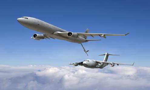
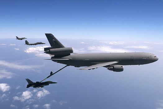
22 Figure2. 5 KC-135R Figure2. 6 KC-767 Figure2. 7 KC-30 Figure2. 8 KC-10 7
23 3.0 configuration design Combined configurations for existing designs, the KC-X will use the low wing configuration, conventional tail for its empennage, conventional tricycle type landing gear, a high-bypass turbofan propulsion system and two different types (drogue and boom) for the refueling system. The transport fuel could store under-floor of the fuselage. The conventional tricycle landing gear could be landed in very large crab angle in a crosswind. The risk of landing is reduced by this type of landing gear. The KC-X will only use two turbofan engines placed symmetrically on the wing. With this configuration, less maintenance efforts will be required. The configuration sketch is shown in figure 3.1 and figure 3.2. Figure3. 1 Configuration Sketch 8
24 Figure3. 2 Configuration Sketch 9
.")
25 4.0 Weight Sizing Before estimate the weight, the linear relationship between empty and takeoff weight is required. For a given value of takeoff weight, the allowable value for empty weight can be found from Eq. (4.1). According to four similar design tanker aircrafts, the design empty and takeoff weight relationship was found by AAA. The numerical value for the quantity A is , B is The result is shown is figure 4.1. W e = inv. log 10 { log 10W To A } (4.1) B Figure4. 1 Empty weight vs. takeoff weight relationship for tankers 10
26 4.1 Mission Fuel Weight According to the mission profile, the fuel-fraction has 8 phases which includes: warm-up, taxi, takeoff, climb, cruise, loiter, descent and landing. The fuel-fraction for each phase is defined as the ratio of end weight to begin weight. Assume fuel-fraction ratios for warm-up, taxi and takeoff are Assume the climb rate is 1500 feet per minute, average climb speed is 275 knots and the fuel-fraction for climb is Assume the SFC for the KC-X is 0.5 and the lift to drag ratio is 14 during cruise. Eq. (4.2) shows the fuel-fraction for cruise. Climb to 40,000 feet require 26.6 minutes and the climb range is 122 nautical miles. The cruise range is 1288 nautical miles. The fuel-fraction for cruise is Assume SFC is 0.6 during loiter and the lift to drag ratio is 16. The fuel-fraction for loiter is Assume the fuel-fraction for descent and landing is The overall mission fuel-fraction is 0.814, that means the used fuel weight is 18.6% of the takeoff weight. Assume 5% reserve fuel; the total fuel weight is 19.5% of the takeoff weight. W i = exp ( RC j (4.2) W i 1 ) V L D W i L D = exp ( EC j ) (4.3) W i 1 Figure4. 2 Mission profile 11
27 4.2 Weight Estimation According to Roskam s weight estimation method, the first step is to calculate the tentative value for operating empty weight and the second is to calculate the tentative value for empty weight. Eq. (4.4) and Eq. (4.5) are these two steps. Compare the tentative value empty weight to numerical empty weight shown in figure 4.1. The tolerance for the empty is 0.5% in the design process. The fuel weight is 0.195% of the takeoff weight, mission payload is 15,000 lbs, 200 lbs for each crew and assume 0.5% trapped fuel. The result is shown in figure 4.3, the takeoff weight is 330,000 lbs and the empty weight is 113,300 lbs. W OEtent = W Toguess W F W PL (4.4) W Etent = W OEtent W tfo W crew (4.5) Weight Estimation between Tentative and Numerical Empty Weight Tentative empty weight Numerical empty weight Empty weight (lbs) Takeoff weight (lbs) Figure4. 3 Weight estimation between tentative and numerical empty weight 12
28 4.3 Sensitivity Studies The sensitivity studies will show how aircraft takeoff weight varies with payload, empty weight, range, endurance, lift to drag ratio and specific fuel consumption. These study could assist aircraft adjust the takeoff weight if these parameters change. Here define three values C, D and F for convenient calculation. Eq. (4.9) to Eq. (4.13) are sensitivity equations for jet aircraft. Results are shown in table 4.1. C = {1 (1 + M res )(1 M ff ) M tfo } (4.6) D = (W PL + W crew ) (4.7) F = BW To 2 (1+M res )M ff CW To (1 B) D (4.8) W To BW = To (4.9) W PL D C(1 B)W To W To W E = BW To invlog 10 { log 10W To A } B (4.10) W To = FC j R V( L D ) (4.11) W To E = FC j ( L (4.12) D ) W To ( L D V( L D = FRC j (4.13) ) )2 13
29 Table4. 1 Sensitivities to different parameters Takeoff weight to payload weight 3.66 Takeoff weight to empty weight 1.92 Takeoff weight to range Takeoff weight to lift-to-drag ratio lb/nm lb 4.4 Trade studies Figure 4.4 shows the trade studies for payload and range. The main payload for the KC-X is fuel. It can be easily stored in the wing, so there is no upper limit for the payload weight. The minimum range requirement is the distance between Okinawa and South Korea which is 705 nautical miles. In this graph, the KC-X has the ability to undertake the refueling mission and the range for eighteen military pallets payloads also fits the cargo mission requirements. 14
30 Trade Study Payload VS Range Graph Payload (lbs) Range (nautical miles) Figure4. 4 Payload vs. range graph 15
31 5.0 Performance Sizing Airplanes are usually designed to meet performance objectives in stall speed, takeoff field length, landing field length, cruise speed climb requirements. Wing area, takeoff thrust, maximum takeoff lift and maximum landing lift coefficient were affected by these performance. From these data, highest possible wing loading and lowest possible thrust to weight could be found with the lowest weight and the lowest cost. 5.1 Zero Lift Drag Estimation Before calculate the performance requirements, the zero lift drag coefficient needs to be estimated. Accord to historical aircraft data, Roskam uses the log plot to find a numerical relation between equivalent parasite area and wetted area with different equivalent skin friction coefficient (Eq. 5.2). Figure 5.1 and 5.2 are the log plot from Roskam s. Assume the skin friction coefficient is 0.004, the value for a and b are and 1. The value for c and d is and for military transports. Combine Eq. (5.2) and Eq. (5.3) can get the equivalent parasite area from the takeoff weight. The zero lift drag coefficient for the KC-X is W/S. C D0 = f S (5.1) log 10 f = a + blog 10 S wet (5.2) log 10 S wet = c + dlog 10 W To (5.3) f = invlog 10 {a + b(c + dlog 10 W To )} (5.4) 16
32 C D0 = invlog 10 {a+b(c+dlog 10W To )} W To W To S (5.5) Equicalent parasite area (ft 2 ) Equivalent Parasite Area VS Wetted Area Cf= Wetted area (ft 2 ) Figure5. 1 Equivalent parasite area vs. wetted area Wetted Area VS Takeoff Weight Military transport Wetted area (ft 2 ) Takeoff weight (lbs) Figure5. 2 Wetted area vs. takeoff weight 17
33 5.2 Takeoff Distance Requirement The runway of Kadena Air Base in Okinawa is 12,140 feet long; the runway of Andersn Air Base in Guam is 11,155 and 10,555 feet long. The design takeoff distance for the KC-X is 10,000 feet. Eq. (5.6) shows the takeoff distance requirement for military aircrafts. Figure 5.3 shows the result for manual takeoff distance requirement calculations. S TOG = ( W S ) to ρ[c L max λ 4+λ T W to C D0 ] (5.6) 0.4 Thrust to Weight Ratio (lbs/lbs) Takeoff requirement for CLmax= Wing Loading (lbs/ft 2 ) Figure5. 3 Takeoff distance requirement for CLmax=1.4 18
34 5.3 Landing Distance Requirement The design landing distance for the KC-X is also 10,000 feet. Eq. 5.7 shows the landing distance requirement for military aircrafts. For maximum landing lift coefficient 1.8, the maximum wing loading is 148. Result is shows in figure 5.4. S FL = 2W S ρc L max (5.7) 0.4 Landing requirement for CLmax=1.8 Thrust to Weight Ratio (lbs/lbs) Wing Loading (lbs/ft 2 ) Figure5. 4 Landing distance requirement for CLmax=1.8 19
35 5.4 One Engine Climb Requirement Eq. (5.8) shows one engine failure climb requirement, N is the engine number and CGR is the climb gradient. The climb rate of the KC-X is 1500 feet minute and the average climb speed is 275 knots. The climb gradient is 0.053, the configuration is gear up, flaps up and maximum continuous thrust on remain engines is 1.25 stall speed. The result is shown is figure 5.5. C L 2 πae T = N C D0 + + CGR (5.8) W C L 0.4 Thrust to Weight Ratio (lbs/lbs) Climb requirement Wing Loading (lbs/ft 2 ) Figure5. 5 One engine failure climb requirement 20
36 5.5 Cruise Speed Requirement Eq. (5.9) shows the cruise requirement for jet aircrafts. The cruise speed of the KC-X is 0.83 and the aspect ratio use 10. Result is shown in figure 5.6. T W = C D 0 q S W + W qsπae (5.9) 0.4 Thrust to Weight Ratio (lbs/lbs) Cruise requirement Wing Loading (lbs/ft 2 ) Figure5. 6 Cruise speed requirement for aspect ratio 10 21
37 5.6 Matching for All Requirements Combine figure 5.3 to figure 5.6, takeoff distance, landing distance, one engine failure climb and cruise speed requirements are all shown in figure 5.7. The best design point P is takeoff lift coefficient 1.4, the lowest thrust to weight ratio 0.23 and the highest wing loading 120. Figure 5.8 shows the AAA results. Thrust to Weight Ratio (lbs/lbs) Takeoff requirement for CL max =1.4 Cruise requirement Climb requirement Landing requirement for CL max = Wing Loading (lbs/ft 2 ) Figure5. 7 Manual performance requirement results 22

38 Figure5. 8 AAA performance requirement results 5.7 Thrust The thrust could be calculated from the takeoff thrust to weight ratio is the lowest thrust to weight ratio fit all performance requirements. The total thrust for 23

39 the KC-X is pounds, pounds for each engine. Model CF6-6 engine (shown in fig 5.9) from GE Company has maximum power of lbs. It was also select for the DC-10. SFC at maximum power is 0.35, the dry weight is 8200 pounds, the length is 16 feet and maximum diameter is 8.75 feet. Figure5. 9 CF6-6 engine Table5. 1 Properties of CF6-6 engine Max Diameter (inch) 105 Length (inch) 188 Dry Weight (lb) 8200 SFC 0.35 Max Power at sea level(lbf) Pressure Ratio Bypass Ratio

40 6.0 Fuselage According to different missions, the fuselage length should allow 150 passengers or 18x464L military cargo pallets. The total length of the fuselage is 150 feet, the maximum diameter of the fuselage is feet and th length of the fuselage cone is feet. The definition of geometric fuselage parameters are shown in figure 6.1. The thickness of the fuselage is 5.5 inches. Figure6. 1 General arrangement of the fuselage 6.1 Cabin Figure 6.2 shows the top view of the cabin for cargo and medical evacuation mission. For the medical evacuation mission, comfert is the the first requirement. The cabin will have two level classes. The first class will contain enght wide and comfert seats for officers and serious injuries. The first class have two rows, four seats per row. Seats in the first class could adjust 45 degrees, requireed length is 50 inches. The other cabin has 143 seats, 17 rows for minor injuries, seven seas per row, four rows for medical staff, six seats per row. All seats could bend 30 degrees for rest and the require length is 47 inches. For cargo mission, the length of the 464L military is
41 inches and 88 inches in width. 150 feet is an enough length for nine pallets and the width could allow two pallets, 18 pallets is the total carrying number. Figure 6.3 shows the cabin cross section area. The first level is 8 feet high and wide. The thickness of the handling floor is 1 feet in order to handle heavy cargos in cargo mission. The hight of the lower level is 9.3 feet for the wing and extra fuel tank mounted in the fuselage. Figure6. 2 Cabin top view 26

42 Figure6. 3 Cabin cross section 6.2 Cockpit Figure 6.4 illustrate the visibilities for the cockpit. The horizontal visibility ranges are from 136 degrees port to 114 degrees starboard. The vertical visibility range is 16 degrees up and down. 27

43 Figure6. 4 Visibilities for the cockpit 28
44 7.0 Wing From the performance requirements, the wing loading for thrust to weight ratio 0.23 is 120. The wing area calculated form that is 2750 ft 2. The aspect ratio used for the cruise requirement is 10. The KC-X will use this aspect ratio to calculate the span and chord length. The tapper ratio selected for the KC-X is The span length is feet. The root chord length is feet and the tip chord is 8.6 feet. b w = AR S w = = ft C r = C t = 2b (1 + λ)ar = = ft ( ) 10 2bλ = = 8.6 ft (1 + λ)ar ( ) Thickness ratio and sweep angle The thickness ratio will follow Roskam s sweep angle relation figure. Eq. (7.1) shows the relationship between Mach number, cruise lift coefficient, thickness ratio and sweep angle. Thickness ratio cannot be less than 0.1 to allow enough room for the wing structure and the fuel. It also should not be over 0.2 because the profile drag of the wing is going to be too high. According to Roskam s preliminary design part, Eq. (7.2) provides the approximate cruise lift coefficient. Figure 7.1 shows the result for thickness ratio and sweep angle relation. The Thickness ratio selected for the KC-X is 0.12 and the leading edge sweep angle is 50 degrees. 29
 Figure7.")
45 (7.1) C Lcr = W TO 0.4W F qs = = 0.59 (7.2) Thickness Ratio and Leading Edge sweep Angle Relation 0.16 Thickness ratio Leading edge sweep angle (degree) Figure7. 1 Thickness ratio and leading edge sweep angle relation 30
, the lift slop for this airfoil is 6.4744, zero lift angle is -2 degrees, stall angle is 15 degrees. NACA 64 1-412 (fig. 7.3) is the tip airfoil for the KC-X.")
46 7.2 Airfoil Due to the thickness ratio is 12%, the KC-X will use thickness 12% airfoils for both root and tip for easy calculations. The airfoil selected for the root is NACA (fig. 7.2), the lift slop for this airfoil is , zero lift angle is -2 degrees, stall angle is 15 degrees. NACA (fig. 7.3) is the tip airfoil for the KC-X. The lift slope for the NACA airfoil is 6.171, zero lift angle is 1, stall angle is 15 degrees. The incidence angle for the root is 10 degrees and the tip has a -2 degrees twist. The wing has a washout design, the wing root stalls before the wing tip in order to provide the KC-X with continued aileron control. The lifting line method is used to determine the lift distribution of the wing. The zero angle of attack lift coefficient for an unsweep wing is Figure 7.4 illustrate the zero angle of attack lift distribution for the wing. For a 50 degrees sweep wing, the lift coefficient is 0.59 which is high enough to keep the KC-X fly level. The maximum lift coefficient is 0.9, figure 7.5 shows the lift distribution for the maximum lift coefficient at 5 degrees angle of attack. Figure7. 2 NACA airfoil 31

47 Figure7. 3 NACA airfoil Figure7. 4 Zero angle of attack lift distribution 32

48 Figure degrees angle of attack lift distribution 7.3 CAD Model The semi-wing CAD model is shown in figure 7.6. A 50 degrees sweep back straight wing, the semi-length of the span is feet, the root chord length is feet, the tip chord length is 8.6 feet and the mean aerodynamic chord is feet. The lift coefficient is 0.64 at zero angle of attack. The wing will have a 3 degrees dihedral for control and stability. 33
49 Figure7. 6 CAD model of the wing 7.4 Flaps According to the takeoff and landing requirements, the takeoff lift coefficient is 1.4 and the landing coefficient is 1.8 for 10,000 feet runway takeoff and landing. Eq. (7.3) to Eq. (7.5) determined required incremental section maximum lift coefficient with flap down. The wing of the KC-X will include a double-slotted fowler flap on the trailing edge. The flap start from 20% to 50% of the semi-span and the chord is 20% of the airfoil. Eq. (7.6) presents the incremental section lift coefficient due to the fowler flap. Compare results from Eq. (7.1) and Eq. (7.4), the flap deflection angle during takeoff is 13 degrees and 24 degrees during landing. Figure 7.9 shows the CAD model of the flaps. 34
50 C lmax = C Lmax ( S S )K Λ (7.3) wf K Λ = (1 0.08cos 2 Λc )cos3 4Λc 4 (7.4) 4 S wf S = (η 0 η i ) 2 1 λ (η i + η 0 ) /(1 + λ) (7.5) C l = 2π(1 + cf c)a δf δ f (7.6) Figure7. 7 Definition of flapped wing area Figure7. 8 Section lift effectiveness parameter for fowler flap 35

51 Figure7. 9 CAD model for flaps 7.5 Aileron The aileron for thx KC-X will start from 55% to 90% of the semi-span; the chord is 20% of the airfoil. Total aileron area is feet square. Compare to similar designs, the aileron to wing area ratio is close. Table 7.1 shows the ratio for KC-767 and KC-10. Figure7. 10 CAD model of aileron 36
52 Table7. 1 Similar aircraft aileron area Wing Area Aileron Area Aileron to Wing ratio KC-767 3,050 ft ft KC-10 3,958 ft ft KC-X 2,750 ft ft Fuel Volume The KC-X will transport 150,000 lbs of JP-4. For the transport fuel mission, the KC-X has to carry total lbs fuel. In the preliminary design, Torenbeek wing fuel volume equation is used to estimate the wing fuel volume. Eq. (7.7) is the Torenbeek wing fuel volume equation. The root and tip thickness are both The KC-X could carry total cubic feet (19035 gallons) of JP-4. Convert to weight; the total weight is lbs lbs fuel will be stored in the fuselage. V WF = 0.54 S2 b (t 1 c) r {(1 + λ W τ 2 w + 2 λw τ w )/(1 + λ w ) 2 (7.7) τ w = (t c ) t ( t c ) w 37
53 8.0 Empennage The area of the empennage was determined using the tail volume coefficient method. The recommended horizontal stabilizer volume coefficient for military cargo aircraft is 1 and the vertical stabilizer volume coefficient is The KC-X will use all moving vertical stabilizer so the vertical volume coefficient could be reduced 15%. Eq. (8.1) and Eq. (8.2) express the volume coefficient; the moment is an important factor for the volume coefficient. The length of the moment arm is the distance from the wing quarter mean chord to the horizontal stabilizer or vertical stabilizer quarter mean chord. The moment arm for the horizontal stabilizer is 57% of the fuselage length and 50% for the vertical stabilizer. C HT = L HTS HT C w S w (8.1) C VT = L VTS VT b w S w (8.2) 38
54 Figure8. 1 Moment arm for the tail volume coefficient 8.1 Horizontal Stabilizer Rewrite Eq. (8.1), the area of the horizontal stabilizer is square feet. The sweep angle for the horizontal stabilizer is 45 degrees, the aspect ratio is 4 and the tapper ratio is 0.4. The span length is feet, semi-span length is feet, the root chord length is feet, the tip chord length is 6.85 feet and the mean aerodynamic chord is feet. S Ht = C Ht C w S w /L Ht (8.3) S HT = = ft 2 39

55 b w = AR S w = = ft C r = C t = 2b (1 + λ)ar = = ft ( ) 4 2bλ = = 6.85 ft (1 + λ)ar ( ) 4 Figure8. 2 CAD model for the horizontal stabilizer 8.2 Vertical Stabilizer The area of the Vertical stabilizer is square feet. The sweep angle for the horizontal stabilizer is 45 degrees, the aspect ratio is 1.3 and the tapper ratio is 0.6. The span length is feet, the root chord length is feet, the tip chord length is feet and the mean aerodynamic chord is 18.2 feet. S vt = C vt b w S w /L vt (8.4) 40

56 S VT = = ft 2 b w = AR S w = = ft C r = C t = 2b (1 + λ)ar = = ft ( ) 1.3 2bλ = = ft (1 + λ)ar ( ) 1.3 Figure8. 3 CAD model for the vertical stabilizer 8.3 Elevator The elevator for the KC-X will start from 20% to 95% semi-span of the horizontal stabilizer; the chord is 35% of the airfoil. Total elevator area is feet square. 41

57 Compare to similar designs, the aileron to wing area ratio is close. Table 8.1 shows the ratio KC-767 and KC-10. Figure8. 4 CAD model of elevator Table8. 1 Similar aircraft elevator area Wing Area Elevator Area Elevator to Wing ratio KC ft ft KC ft ft KC-X ft ft
58 9.0 Weight and Balance The maximum takeoff weight of the KC-X is 330,000 pounds. Table 9.1 shows a roughly estimated weight. All weight components are from GD weight method or Torenbeek method from Roskam s Class II weight estimation. Some of the components were using USAF weight method. The distances where the moments were computed were taken with respect to the front of the airplane, towards the cockpit nose, and measured along an access parallel to the approximate center of gravity distance of a particular component. The same procedure is carried out with the useful load for each mission s center of gravity. Table 9.1 shows the weight and distance to the nose for each component. Figure 8.1 shows the C.G. diagram, point 1 is the empty C.G. location. Point 2 add 3 crews, at point 3 and 4 add transport fuel and mission fuel. Point 5 finish refueling with half mission fuel then landing. Table9. 1 Component weight Name Weight Distance to nose Moment Wing 28,859 lb 68 ft lb-ft Horizontal Stabilizer 1, lb 154 ft lb-ft Vertical Stabilizer 2,236.2 lb 142 ft lb-ft Fuselage 30,549 lb 70 ft lb-ft Nacelle 3,202.4 lb 52 ft lb-ft Main Gear 15,694 lb 70 ft lb-ft Nose Gear 1,896 lb 15 ft lb-ft Engine 16,350 lb 52 ft lb-ft Fuel System 1,055.3 lb 40 ft lb-ft Flight Control 4,320 lb 10 ft lb-ft Avionic 2,311 lb 10 ft lb-ft APU 2,640 lb 145 ft lb-ft Furnishing 184 lb 15 ft lb-ft Electrical System 2, ft lb-ft Total 113, lb ft lb-ft 43

59 Figure9. 1 C.G diagram for refueling mission Figure9. 2 Empty weight C.G location 44
60 10.0 Landing Gear The KC-X uses the tricycle fuselage mounted gears. The main gear with two struts, four wheels per strut and two wheels for the nose gear strut. According to different center gravity locations, the gear would bear different loads. The maximum load for the main gear wheel is 39,270 lb when the C.G. location is at feet from nose and the maximum load for the nose gear is 28,900 lb when the C.G. location is at feet from the nose. Table 10.1 shows the wheel information; selected wheel for the main gear is type VII with maximum load of 41,700 lb in 44 inches diameter and 18 inches wide. The wheel for the nose is new design type with maximum load of 29,300 lb in 37 inches diameter and 13 inches wide. P n = W tol m (l m +l n ) P m = W tol n n s (l m +l n ) (10.1) (10.2) Figure10. 1 Static load geometric for tricycle gears 45
61 Table10. 1 Selected wheel data Gear Type DoxW Maximum Load Nose Gear New Design Type 37 x lb Main Gear Type VII 44 x lb 46
62 11.0 Stability and Control Analysis In order to find appropriate horizontal stabilizer are and vertical stabilizer area, longitudinal stability and directional stability will be analyzed via longitudinal X-plot and directional X-plot in this chapter Static Longitudinal Stability The static longitudinal stability will be based on Roskam s method. The longitudinal X-plot is used to define the ideal horizontal stabilizer area. The GD method from Roskam is used for the center gravity graph shown in Eq. (11.1). W h = {(W TO n ult ) (S h ) b h C 0.28 } (11.1) t rh l h A relationship between horizontal stabilizer area and weight is determined from Eq. (11.1). Using weights from chapter 9, the relationship between the center gravity location and horizontal stabilizer area can be found. To calculate the aerodynamic center location, Roskam use Eq. (11.2) and Eq. (11.3) to determine the horizontal stabilizer area and aerodynamic center relationship. X aca = X acwf + C L αh 1 ε h α (S h S )Xac h C Lαwf F (11.2) F = 1 + C L αh 1 ε h α (S h S ) C Lαwf (11.3) 47
63 Eq. (11.4) to Eq. (11.8) can be used to solve the wing-fuselage coefficient, wing lift curve slope, Mach constant and Mach variable for the wing-fuselage lift curve slope. C Lαwf = k wf C Lαw (11.4) k wf = d f b 0.25(d f b )2 (11.5) C Lαw = 2πA 2+[ A2 B 2 k 2 +4]2 (11.6) β = (1 M 2 ) (11.7) k = (C lα ) M 2π β (11.8) To calculate the horizontal lift curve slope, replace Eq. (11.6) aspect ratio and airfoil lift curve slop values for the horizontal stabilizer. Eq. (11.9) to Eq. (11.12) are the Roskam s method to solve the aspect ratio coefficient, the taper ratio coefficient and the horizontal stabilizer coefficient for the downwash gradient at the horizontal stabilizer. 4.44(KAKλKh cos Λ ε h = 1 ) α (1 M 2 ) (11.9) K A = 1 1 A 1+A1.7 (11.10) K λ = (10 3λ) 7 (11.11) K h = 1 h h b (11.12) 3 ( 2l h b ) 48
64 Figure 11.1 shows the result combine Eq. (11.2) to Eq. (11.12). Assume a 10% static of margin which is commonly used for aircrafts, the required horizontal stabilizer area from figure 11.1 shows 570 ft 2. The initial design horizontal stabilizer area is ft 2. These two values are very close. The horizontal stabilizer area will not change. 68 Longitudinal Stability X-Plot Distance From Tip of Nose (ft) Xcg XacA Horizontal Stabilizer Area (ft 2 ) Figure11. 1 Longitudinal stability X-Plot 11.2 Static Directional Stability A relationship between the yaw side-slip moment coefficient and the vertical stabilizer area from Roskam were shown in Eq. (11.13): C nβ = C nβwf + C LαV S v S (X v b ) (11.13) Assume the wing yaw side-slip coefficient be zero at high angle of attack, the 49
65 fuselage yaw side-slip coefficient is defined in Eq. (11.14): C nβf = 57.3K N K Rl ( S fs l f Sb ) (11.14) The value of K N is empirical factor determined from figure 11.3 and K Rl is a factor depends on Reynold s number from figure Figure 11.2 shows the directional stability X-plot result from Eq. (11.13) and Eq. (11.14). When the yaw side-slip moment coefficient is equal to 0.001, the recommended vertical stabilizer area is 321 ft 2. The initial design vertical stabilizer area is ft 2. The appropriate vertical stabilizer area from this chapter is 77% of the initial design. The smaller vertical stabilizer area number from t his chapter will be used in order to reduce the tail weight. Yaw Side-slip Moment Coefficient Directional Stability X-Plot Vertical Stabilizer Area (ft 2 ) Figure11.2 Directional stability X-Plot 50
66 Figure11. 3 Factor accounting for wing-fuselage interference with directional stability 51

67 Figure11. 4 Effect of fuselage Reynolds number on wing fuselage directional stability 52
68 12.0 Drag Polar Estimation In section 5.1, an assumption of drag polar is made for the military aircraft performance requirement. In this chapter, the drag polar will be calculated based on Roskam s method then compare to the drag assumed in chapter Zero Lift Drag To calculate the zero lift drag, the wetted area is required to be calculated. The wetted area is split into different components include: wing, empennage, fuselage and nacelles. Eq. (12.1) shows the total wetted area of the airplane is the sum of wetted area from different components. S wet,tot = S wet,w + S wet,e + S wet,f + S wet,n (12.1) Eq. (12.2) to Eq. (12.6) is used to calculate the wetted area for different components. Eq. (12.2) will be specific used for the wing, horizontal stabilizer and vertical stabilizer. S wet,w = 2S exp t c r (1+τλ) (1+λ) The fuselage wetted area can be calculated using Eq. (12.3) (12.2) S wet,f = πd f l f λ ( ) (12.3) f λf The nacelle includes fan cowling, gas generator and the plug. Eq. (12.4) to Eq. (12.6) shows the wetted area of these components. S wet,fan = l n D n l 1 ln l 1D h1 ln D n l 1 ln D ef Dn (12.4) 53
69 S wet,gas = πl g D g D eg 3 Dg D g lg 5 3 (12.5) S wet,plug = 0.7πl p D p (12.6) Table 12.1 express the wetted area of these components and the total wetted area is 21,657.7 ft 2. Back to Eq. (12.2), the equivalent parasite area is 82.5 ft 2. The zero-lift drag coefficient can be determined using Eq. (5.1) with the value for the parasite area and the wing area, the zero-lift drag coefficient becomes Table12. 1 Wetted area for different components Fuselage ft 2 Fan Cowling ft 2 Wing ft 2 Gas Generator ft 2 Horizontal Stabilizer 1839 ft 2 Plug ft 2 Vertical Stabilizer ft 2 Total ft Drag Polar Using the value of zero-lift drag coefficient, the overall drag coefficient can be calculated from Eq. (12.7): C D = C D0 + C L 2 πear (12.7) The drag polar and lift to drag ratio at various lift coefficient are shown in figure 12.1 and figure 12.2: 54
70 3.5 Drag Coefficient vs. Lift Coefficient 2.8 Lift COefficient (C L ) Drag Coefficient (C D ) Figure12. 1 CD vs. CL 3.5 Lift to drag Ratio vs. Lift Coefficient 2.8 Left Coefficnent (C L ) Lift to Drag Ratio (L/D) Figure12. 2 L/D vs. CL 55
71 Using the cruising lift coefficient of 0.59 and the Oswald efficient factor of 0.85, the total drag coefficient during cruise is Assume the lift coefficient stays constant, the lift to drag ratio can be calculated: L D = C L C D = = In chapter 5, the preliminary assumptions of the cruising lift to drag ratio is 14 and the calculated lift to drag ratio is From the sensitivity analysis data in section 4.3: W To ( L D ) = 8299 lb The decrease in lift to drag ratio from 14 to 13.72, the takeoff weight needs to be increased by 2324 lbs. This weight will be used for more advanced structural protections for the fuel tank. 56
72 13.0 V-N Diagram The generation of lift during high-g maneuvers typically accounts for the greatest aero load on the airplane. At high speeds the maximum load factor is limited to the chosen value based upon the expected use of the airplane. The V-N diagram, of the airplane describes these basic flight performance limits. The recommended maximum load factors from Roskam for military transporter are positive two and negative one. A V-N diagram for the KC-X is shown in the figure Vs is the 1G stall speed at which the KC-X is controllable. V a is the design maneuvering speed at maximum load factor. V c is the design cruise speed and V d is the design diving speed. V S = 2W S ρc N max = = ft/s= kt V a = V S 2 = ft/s= kt V C = ft/s= kt V d = 1.25V c = ft/s= kt 57
73 Load factor V-N Diagram 2 A D 1 V S V A V C E Velocity (knot) -1 H F Figure13. 1 V-N diagram for the KC-X 58
74 14.0 Conclusion East Asia is the heart of the world high technology includes the place of origin of rare earth metals and the key position of development and OEM. Once the war start, the global economic will be inflict heavily and the great depression might come out again. The KC-X is tailored for the East Asia deployment with high cargo capacity and low noise. In the future, the KC-X could assist the movement of marine troop from Okinawa to Guam and also protect the environment for these beautiful islands from military competitions. The government could consider the KC-X, the new stratotanker of environment protector to reduce the environment impacts. 59
75 15.0 Reference 1. Federal Business Opportunities ( 2. K. K. Ishimitsu, Aerodynamic design and analysis of winglets, AIAA paper , Sep, N. Gold, K.D. Visser, Aerodynamic effects of local dihedral on a raked wingtip, AIAA Paper J.F. Halpert, D.H. Prescott, T.R. Yechout, M. Arndt, Aerodynamic optimization and evaluation of KC-135R winglets, raked wingtips, and a wingspan extension AIAA Aerospace Science Meeting, Jan, P. Gerontakos, T. Lee, Effects of winglet dihedral on a tip vortex, Journal of Aircraft, Vol. 43, No. 1, Jan-Feb J.W. Slooff, W.B. Wolf, Aerodynamic and aero-acoustic effects of flap tip fences, AIAA paper Home of the USAF KC-10A Extender ( 8. Roskam, Jan. Airplane Design. Lawrence, Kan.: DARcorporation, Print. 9. Raymer, Daniel P. Aircraft Design: a Conceptual Approach. 2nd ed. Reston, VA: American Institute of Aeronautics and Astronautics, Print. 10. GE aviation ( 11. Lifting line theory matlab code ( 12. I. H. Abbott, A. E. Von Doenhoff, Theory of wing sections, Dover publications, INC. 60
76 Appendix A. Front, Side and Top Views of the KC-X 61
77 62
AE 451 Aeronautical Engineering Design Final Examination. Instructor: Prof. Dr. Serkan ÖZGEN Date:
 Instructor: Prof. Dr. Serkan ÖZGEN Date: 11.01.2012 1. a) (8 pts) In what aspects an instantaneous turn performance is different from sustained turn? b) (8 pts) A low wing loading will always increase
The Airplane That Could!
 The Airplane That Could! Critical Design Review December 6 th, 2008 Haoyun Fu Suzanne Lessack Andrew McArthur Nicholas Rooney Jin Yan Yang Yang Agenda Criteria Preliminary Designs Down Selection Features
Aircraft Design Conceptual Design
 Université de Liège Département d Aérospatiale et de Mécanique Aircraft Design Conceptual Design Ludovic Noels Computational & Multiscale Mechanics of Materials CM3 http://www.ltas-cm3.ulg.ac.be/ Chemin
AIRCRAFT DESIGN SUBSONIC JET TRANSPORT
 AIRCRAFT DESIGN SUBSONIC JET TRANSPORT Analyzed by: Jin Mok Professor: Dr. R.H. Liebeck Date: June 6, 2014 1 Abstract The purpose of this report is to design the results of a given specification and to
AE 451 Aeronautical Engineering Design I Estimation of Critical Performance Parameters. Prof. Dr. Serkan Özgen Dept. Aerospace Engineering Fall 2015
 AE 451 Aeronautical Engineering Design I Estimation of Critical Performance Parameters Prof. Dr. Serkan Özgen Dept. Aerospace Engineering Fall 2015 Airfoil selection The airfoil effects the cruise speed,
AIAA UNDERGRADUATE TEAM DESIGN COMPETITION PROPOSAL 2017
 TADPOLE AIAA UNDERGRADUATE TEAM DESIGN COMPETITION PROPOSAL 2017 Conceptual Design of TADPOLE Multi-Mission Amphibian MIDDLE EAST TECHNICAL UNIVERSITY 5-10-2017 Team Member AIAA Number Contact Details
THE ANALYSIS OF WING PERFORMANCE FOR RECONNAISSANCE UAV ZULKIFLI BIN YUSOF UNIVERSITI MALAYSIA PAHANG
 THE ANALYSIS OF WING PERFORMANCE FOR RECONNAISSANCE UAV ZULKIFLI BIN YUSOF UNIVERSITI MALAYSIA PAHANG The Analysis of Wing Performance for Reconnaissance UAV ZULKIFLI BIN YUSOF Report submitted in partial
Chapter 2 Lecture 5 Data collection and preliminary three-view drawing - 2 Topic
 Chapter 2 Lecture 5 Data collection and preliminary three-view dra - 2 Topic 2.3 Preliminary three-view dra Example 2.1 2.3 Preliminary three-view dra The preliminary three-view dra of the airplane gives
ECO-CARGO AIRCRAFT. ISSN: International Journal of Science, Engineering and Technology Research (IJSETR) Volume 1, Issue 2, August 2012
 Volume 1, Issue 2, August 2012") ECO-CARGO AIRCRAFT Vikrant Goyal, Pankhuri Arora Abstract- The evolution in aircraft industry has brought to us many new aircraft designs. Each and every new design is a step towards a greener tomorrow.
ECO-CARGO AIRCRAFT Vikrant Goyal, Pankhuri Arora Abstract- The evolution in aircraft industry has brought to us many new aircraft designs. Each and every new design is a step towards a greener tomorrow.
TEAM Four Critical Design Review. Kai Jian Cheong Richard B. Choroszucha* Lynn Lau Mathew Marcucci Jasmine Sadler Sapan Shah Chongyu Brian Wang
 TEAM Four Critical Design Review Kai Jian Cheong Richard B. Choroszucha* Lynn Lau Mathew Marcucci Jasmine Sadler Sapan Shah Chongyu Brian Wang 03.XII.2008 0.1 Abstract The purpose of this report is to
PAC 750XL PAC 750XL PAC-750XL
 PAC 750XL The PAC 750XL combines a short take off and landing performance with a large load carrying capability. The PAC 750XL is a distinctive type. Its design philosophy is reflected in the aircraft's
Aircraft Design in a Nutshell
 Dieter Scholz Aircraft Design in a Nutshell Based on the Aircraft Design Lecture Notes 1 Introduction The task of aircraft design in the practical sense is to supply the "geometrical description of a new
CONCEPTUAL DESIGN REPORT
 CONCEPTUAL DESIGN REPORT Agricultural Unmanned Aircraft System (AUAS) Team Two-CAN Team Member Albert Lee (Team Leader) Chris Cirone Kevin Huckshold Adam Kuester Jake Niehus Michael Scott Area of Responsibility
Multidisciplinary Design Optimization of a Strut-Braced Wing Transonic Transport
 Multidisciplinary Design Optimization of a Strut-Braced Wing Transonic Transport John F. Gundlach IV Masters Thesis Defense June 7,1999 Acknowledgements NASA LMAS Student Members Joel Grasmeyer Phillipe-Andre
Flugzeugentwurf / Aircraft Design SS Part 35 points, 70 minutes, closed books. Prof. Dr.-Ing. Dieter Scholz, MSME. Date:
 DEPARTMENT FAHRZEUGTECHNIK UND FLUGZEUGBAU Flugzeugentwurf / Aircraft Design SS 2015 Duration of examination: 180 minutes Last Name: Matrikelnummer: First Name: Prof. Dr.-Ing. Dieter Scholz, MSME Date:
Three major types of airplane designs are 1. Conceptual design 2. Preliminary design 3. Detailed design
 1. Introduction 1.1 Overview: Three major types of airplane designs are 1. Conceptual design 2. Preliminary design 3. Detailed design 1. Conceptual design: It depends on what are the major factors for
Design Considerations for Stability: Civil Aircraft
 Design Considerations for Stability: Civil Aircraft From the discussion on aircraft behavior in a small disturbance, it is clear that both aircraft geometry and mass distribution are important in the design
Chapter 10 Miscellaneous topics - 2 Lecture 39 Topics
 Chapter 10 Miscellaneous topics - 2 Lecture 39 Topics 10.3 Presentation of results 10.3.1 Presentation of results of a student project 10.3.2 A typical brochure 10.3 Presentation of results At the end
CDR Presentation 26 Nov Dust Thrusters Dain Christensen Julene Forner Jessica Howe Jonathan Newhall David Roman Michael Straka Kyle Vonnahmen
 CDR Presentation 26 Nov 2007 Dust Thrusters Dain Christensen Julene Forner Jessica Howe Jonathan Newhall David Roman Michael Straka Kyle Vonnahmen Overview Constraint Analysis Jonathan Newhall Structures
EAS 4700 Aerospace Design 1
 EAS 4700 Aerospace Design 1 Prof. P.M. Sforza University of Florida Commercial Airplane Design 1 1.Mission specification and market survey Number of passengers: classes of service Range: domestic or international
DEVELOPMENT OF A CARGO AIRCRAFT, AN OVERVIEW OF THE PRELIMINARY AERODYNAMIC DESIGN PHASE
 ICAS 2000 CONGRESS DEVELOPMENT OF A CARGO AIRCRAFT, AN OVERVIEW OF THE PRELIMINARY AERODYNAMIC DESIGN PHASE S. Tsach, S. Bauminger, M. Levin, D. Penn and T. Rubin Engineering center Israel Aircraft Industries
Appenidix E: Freewing MAE UAV analysis
 Appenidix E: Freewing MAE UAV analysis The vehicle summary is presented in the form of plots and descriptive text. Two alternative mission altitudes were analyzed and both meet the desired mission duration.
The Sonic Cruiser A Concept Analysis
 International Symposium "Aviation Technologies of the XXI Century: New Aircraft Concepts and Flight Simulation", 7-8 May 2002 Aviation Salon ILA-2002, Berlin The Sonic Cruiser A Concept Analysis Dr. Martin
Multidisciplinary Design Optimization of a Truss-Braced Wing Aircraft with Tip-Mounted Engines
 Multidisciplinary Design Optimization of a Truss-Braced Wing Aircraft with Tip-Mounted Engines NASA Design MAD Center Advisory Board Meeting, November 14, 1997 Students: J.M. Grasmeyer, A. Naghshineh-Pour,
Design of Supersonic Transport
 Design of Supersonic Transport A project present to The Faculty of the Department of Aerospace Engineering San Jose State University in partial fulfillment of the requirements for the degree Master of
PERFORMANCE ANALYSIS OF UNMANNED AIR VEHICLE INTERCEPTOR (UAV-Ip)
") TH INTERNATIONAL CONGRESS OF THE AERONAUTICAL SCIENCES PERFORMANCE ANALYSIS OF UNMANNED AIR VEHICLE INTERCEPTOR (UAV-Ip) FLT LT MUHAMMAD ASIM AHQ CHAKLALA (PROJ VISION) RAWALPINDI PAKISTAN AIR FORCE, PAKISTAN
TH INTERNATIONAL CONGRESS OF THE AERONAUTICAL SCIENCES PERFORMANCE ANALYSIS OF UNMANNED AIR VEHICLE INTERCEPTOR (UAV-Ip) FLT LT MUHAMMAD ASIM AHQ CHAKLALA (PROJ VISION) RAWALPINDI PAKISTAN AIR FORCE, PAKISTAN
A STUDY OF STRUCTURE WEIGHT ESTIMATING FOR HIGH ALTITUDE LONG ENDURENCE (HALE) UNMANNED AERIAL VEHICLE (UAV)
 UNMANNED AERIAL VEHICLE (UAV)") 5 TH INTERNATIONAL CONGRESS OF THE AERONAUTICAL SCIENCES A STUDY OF STRUCTURE WEIGHT ESTIMATING FOR HIGH ALTITUDE LONG ENDURENCE (HALE UNMANNED AERIAL VEHICLE (UAV Zhang Yi, Wang Heping School of Aeronautics,
5 TH INTERNATIONAL CONGRESS OF THE AERONAUTICAL SCIENCES A STUDY OF STRUCTURE WEIGHT ESTIMATING FOR HIGH ALTITUDE LONG ENDURENCE (HALE UNMANNED AERIAL VEHICLE (UAV Zhang Yi, Wang Heping School of Aeronautics,
Flugzeugentwurf / Aircraft Design WS 10/ Klausurteil 30 Punkte, 60 Minuten, ohne Unterlagen. Prof. Dr.-Ing. Dieter Scholz, MSME
 DEPARTMENT FAHRZEUGTECHNIK UND FLUGZEUGBAU Prof. Dr.-Ing. Dieter Scholz, MSME Flugzeugentwurf / Aircraft Design WS 10/11 Bearbeitungszeit: 180 Minuten Name: Matrikelnummer.: Vorname: Punkte: von 68 Note:
INVESTIGATION OF ICING EFFECTS ON AERODYNAMIC CHARACTERISTICS OF AIRCRAFT AT TSAGI
 INVESTIGATION OF ICING EFFECTS ON AERODYNAMIC CHARACTERISTICS OF AIRCRAFT AT TSAGI Andreev G.T., Bogatyrev V.V. Central AeroHydrodynamic Institute (TsAGI) Abstract Investigation of icing effects on aerodynamic
AeroTactic Company. FF-1 Rainbird
 AeroTactic Company presents the FF-1 Rainbird In response to the 2015-2016 AIAA Foundation Graduate Team Aircraft Design Competition Presented by California State Polytechnic University, Pomona Aerospace
Initech Aircraft is proud to present the JTC-2 E Swingliner in response to the
 ii Executive Summary Initech Aircraft is proud to present the JTC-2 E Swingliner in response to the 2006-2007 AIAA undergraduate design competition. The Swingliner has been developed as a survivable transport
1.1 REMOTELY PILOTED AIRCRAFTS
 CHAPTER 1 1.1 REMOTELY PILOTED AIRCRAFTS Remotely Piloted aircrafts or RC Aircrafts are small model radiocontrolled airplanes that fly using electric motor, gas powered IC engines or small model jet engines.
Preface. Acknowledgments. List of Tables. Nomenclature: organizations. Nomenclature: acronyms. Nomenclature: main symbols. Nomenclature: Greek symbols
 Contents Preface Acknowledgments List of Tables Nomenclature: organizations Nomenclature: acronyms Nomenclature: main symbols Nomenclature: Greek symbols Nomenclature: subscripts/superscripts Supplements
Optimum Seat Abreast Configuration for an Regional Jet
 7 th european conference for aeronautics and space sciences (eucass) Optimum Seat Abreast Configuration for an Regional Jet I. A. Accordi* and A. A.de Paula** *Instituto Tecnológico de Aeronáutica São
Heavy Lifters Design Team. Virginia Polytechnic Institute and State University Free-Weight Final Report Spring 2007
 Heavy Lifters Design Team Virginia Polytechnic Institute and State University Free-Weight Final Report Spring 2007 The Heavy Lifters Leslie Mehl AIAA # 281854 Daniel Opipare AIAA #275371 Dzejna Mujezinovic
AIRCRAFT DESIGN MADE EASY. Basic Choices and Weights. By Chris Heintz
 AIRCRAFT DESIGN MADE EASY By Chris Heintz The following article, which is a first installement of a two-part article, describes a simple method for the preliminary design of an airplane of conventional
Classical Aircraft Sizing I
 Classical Aircraft Sizing I W. H. Mason from Sandusky, Northrop slide 1 Which is 1 st? You need to have a concept in mind to start The concept will be reflected in the sizing by the choice of a few key
Systems Group (Summer 2012) 4 th Year (B.Eng) Aerospace Engineering Candidate Carleton University, Ottawa,Canada Mail:
 4 th Year (B.Eng) Aerospace Engineering Candidate Carleton University, Ottawa,Canada Mail:") Memo Airport2030_M_Family_Concepts_of_Box_Wing_12-08-10.pdf Date: 12-08-10 From: Sameer Ahmed Intern at Aero Aircraft Design and Systems Group (Summer 2012) 4 th Year (B.Eng) Aerospace Engineering Candidate
Memo Airport2030_M_Family_Concepts_of_Box_Wing_12-08-10.pdf Date: 12-08-10 From: Sameer Ahmed Intern at Aero Aircraft Design and Systems Group (Summer 2012) 4 th Year (B.Eng) Aerospace Engineering Candidate
CONCEPTUAL DESIGN OF ECOLOGICAL AIRCRAFT FOR COMMUTER AIR TRANSPORTATION
 26 TH INTERNATIONAL CONGRESS OF THE AERONAUTICAL SCIENCES CONCEPTUAL DESIGN OF ECOLOGICAL AIRCRAFT FOR COMMUTER AIR TRANSPORTATION Yasuhiro TANI, Tomoe YAYAMA, Jun-Ichiro HASHIMOTO and Shigeru ASO Department
SILENT SUPERSONIC TECHNOLOGY DEMONSTRATION PROGRAM
 25 TH INTERNATIONAL CONGRESS OF THE AERONAUTICAL SCIENCES SILENT SUPERSONIC TECHNOLOGY DEMONSTRATION PROGRAM Akira Murakami* *Japan Aerospace Exploration Agency Keywords: Supersonic, Flight experiment,
Design of Ultralight Aircraft
 Design of Ultralight Aircraft Greece 2018 Main purpose of present study The purpose of this study is to design and develop a new aircraft that complies with the European ultra-light aircraft regulations
Aeronautical Engineering Design II Sizing Matrix and Carpet Plots. Prof. Dr. Serkan Özgen Dept. Aerospace Engineering Spring 2014
 Aeronautical Engineering Design II Sizing Matrix and Carpet Plots Prof. Dr. Serkan Özgen Dept. Aerospace Engineering Spring 2014 Empty weight estimation and refined sizing Empty weight of the airplane
DEVELOPMENT OF A MORPHING FLYING PLATFORM FOR ADAPTIVE CONTROL SYSTEM STUDY
 27 TH INTERNATIONAL CONGRESS OF THE AERONAUTICAL SCIENCES DEVELOPMENT OF A MORPHING FLYING PLATFORM FOR ADAPTIVE CONTROL SYSTEM STUDY Taufiq Mulyanto, M. Luthfi I. Nurhakim, Rianto A. Sasongko Faculty
Design of a High Altitude Fixed Wing Mini UAV Aerodynamic Challenges
 Design of a High Altitude Fixed Wing Mini UAV Aerodynamic Challenges Hemant Sharma 1, C. S. Suraj 2, Roshan Antony 3, G. Ramesh 4, Sajeer Ahmed 5 and Prasobh Narayan 6 1, 2, 3, 4 CSIR National Aerospace
An Integrated Approach to the Design-Optimization of an N+3 Subsonic Transport
 An Integrated Approach to the Design-Optimization of an N+3 Subsonic Transport Mark Drela MIT Aero & Astro AIAA 28th Applied Aerodynamics Conference 30 Jun 10 Motivation: NASA s N+3 Program Identify concepts
DESIGN OF AN ARMAMENT WING FOR A LIGHT CATEGORY HELICOPTER
 International Journal of Engineering Applied Sciences and Technology, 7 Published Online February-March 7 in IJEAST (http://www.ijeast.com) DESIGN OF AN ARMAMENT WING FOR A LIGHT CATEGORY HELICOPTER Miss.
AIAA Foundation Student Design Competition 2015/16. Undergraduate Individual Aircraft
 AIAA Foundation Student Design Competition 2015/16 Undergraduate Individual Aircraft Conceptual Design of TAJ PEGASUS A Long Range Container Transportation Aircraft Designer & Author : Waheedullah Taj
A Game of Two: Airbus vs Boeing. The Big Guys. by Valerio Viti. Valerio Viti, AOE4984, Project #1, March 22nd, 2001
 A Game of Two: Airbus vs Boeing The Big Guys by Valerio Viti 1 Why do we Need More Airliners in the Next 20 Years? Both Boeing and Airbus agree that civil air transport will keep increasing at a steady
DESIGN OF A FIFTH GENERATION AIR SUPERIORITY FIGHTER AIRCRAFT
 Proceedings of the International Conference on Mechanical Engineering and Renewable Energy 2015 (ICMERE2015) 26 29 November, 2015, Chittagong, Bangladesh ICMERE2015PI152 DESIGN OF A FIFTH GENERATION AIR
AIAA UNDERGRADUATE INDIVIDUAL DESING COMPETITION: DESIGN AND ANALYSIS OF THE PEGASUS JET TRAINER
 AIAA UNDERGRADUATE INDIVIDUAL DESING COMPETITION: DESIGN AND ANALYSIS OF THE PEGASUS JET TRAINER Instructor: Dr. Ron Barrett Department of Aerospace Engineering May 10, 2014 Designer: AIAA Member ID: 431416
AIAA Foundation Undergraduate Team Aircraft Design Competition. RFP: Cruise Missile Carrier
 AIAA Foundation Undergraduate Team Aircraft Design Competition RFP: Cruise Missile Carrier 1999/2000 AIAA FOUNDATION Undergraduate Team Aircraft Design Competition I. RULES 1. All groups of three to ten
JetBiz. Six and Eight Passenger Business Jets
 JetBiz Presents the Six and Eight Passenger Business Jets In response to the 2016 2017 AIAA Foundation Undergraduate Team Aircraft Design Competition Request for Proposal Presented by California State
10th Australian International Aerospace Congress
 AUSTRALIAN INTERNATIONAL AEROSPACE CONGRESS Paper presented at the 10th Australian International Aerospace Congress incorporating the 14th National Space Engineering Symposium 2003 29 July 1 August 2003
blended wing body aircraft for the
 Feasibility study of a nuclear powered blended wing body aircraft for the Cruiser/Feeder eede concept cept G. La Rocca - TU Delft 11 th European Workshop on M. Li - TU Delft Aircraft Design Education Linköping,
Hawker Beechcraft Corporation on March 26, 2007
 DEPARTMENT OF TRANSPORTATION FEDERAL AVIATION ADMINISTRATION A00010WI Revision 8 Hawker Beechcraft 390 March 26, 2007 TYPE CERTIFICATE DATA SHEET NO. A00010WI This data sheet, which is part of Type Certificate
Ember Aviation LAT-1
 Ember Aviation Presents the LAT-1 In response to the 2015 2016 AIAA Foundation Undergraduate Team Aircraft Design Competition Presented by California Polytechnic State University, Pomona Aerospace Engineering
Power Estimation for a Two Seater Helicopter
 Power Estimation for a Two Seater Helicopter JTSE Mohammad Nazri Mohd Jaafar, a,* Mohd Idham Mohd Nayan, a M.S.A. Ishak, b a Department of Aeronautical Engineering, Faculty of Mechanical Engineering, Universiti
Lecture 5 : Static Lateral Stability and Control. or how not to move like a crab. G. Leng, Flight Dynamics, Stability & Control
 Lecture 5 : Static Lateral Stability and Control or how not to move like a crab 1.0 Lateral static stability Lateral static stability refers to the ability of the aircraft to generate a yawing moment to
INDIAN INSTITUTE OF TECHNOLOGY KANPUR
 INDIAN INSTITUTE OF TECHNOLOGY KANPUR INDIAN INSTITUTE OF TECHNOLOGY KANPUR Removable, Low Noise, High Speed Tip Shape Tractor Configuration, Cant angle, Low Maintainence Hingelesss, Good Manoeuverability,
A PARAMETRIC STUDY OF THE DEPLOYABLE WING AIRPLANE FOR MARS EXPLORATION
 A PARAMETRIC STUDY OF THE DEPLOYABLE WING AIRPLANE FOR MARS EXPLORATION Koji Fujita* * Department of Aerospace Engineering, Tohoku University, Sendai, Japan 6-6-, Aramaki-Aza-Aoba, Aoba-ku, Sendai, Miyagi
Aircraft Design: A Systems Engineering Approach, M. Sadraey, Wiley, 2012 Chapter 3 Aircraft Conceptual Design. Tables
 Aircraft Design: A Systems Engineering Approach, M. Sadraey, Wiley, 2012 Chapter 3 Aircraft Conceptual Design Tables No Component Primary function Major areas of influence 1 Fuselage Payload accommodations
DESIGN THE VTOL AIRCRAFT FOR LAND SURVEYING PURPOSES SHAHDAN BIN AZMAN
 DESIGN THE VTOL AIRCRAFT FOR LAND SURVEYING PURPOSES SHAHDAN BIN AZMAN A report submitted as the first draft of the final year project in semester 1 2016/2017 Faculty of Mechanical Engineering Universiti
TAKEOFF PERFORMANCE ground roll
 TAKEOFF PERFORMANCE An airplane is motionless at the end of a runway. This is denoted by location O. The pilot releases the brakes and pushes the throttle to maximum takeoff power, and the airplane accelerates
AIAA Undergraduate Team Aircraft Design
 Homeland Defense Interceptor (HDI) 2005 2006 AIAA Undergraduate Team Aircraft Design Group Members and Responsibilities Name Discipline AIAA Number John Borgie Configuration and Systems 268357 Ron Cook
American Institute of Aeronautics and Astronautics Undergraduate Individual Aircraft Design Competition Proposal
 American Institute of Aeronautics and Astronautics 2011-2012 Undergraduate Individual Aircraft Design Competition Proposal Alex Lopez Instructor: Dr. Ron Barrett Department of Aerospace Engineering May
Design of a Prototype Model Aircraft Utilizing Propulsive Airfoil Technology
 Syracuse University SURFACE Syracuse University Honors Program Capstone Projects Syracuse University Honors Program Capstone Projects Spring 5-1-2005 Design of a Prototype Model Aircraft Utilizing Propulsive
POWER ESTIMATION FOR FOUR SEATER HELICOPTER
 Jurnal Mekanikal December 2008, No. 27, 78-90 POWER ESTIMATION FOR FOUR SEATER HELICOPTER Ahmad Azlan Shah B. Ibrahim Mohammad Nazri Mohd Jaafar * Faculty of Mechanical Engineering University Technology
The winner team will have the opportunity to perform a wind tunnel test campaign in the transonic/supersonic Wind tunnel at the VKI.
 Aircraft Design Competition Request for proposal (RFP) - High speed UAV Objectives: This RFP asks for an original UAV design capable of reaching, in less than 15 minutes, a given target located at 150
BAYLOR UNIVERSITY DEPARTMENT OF ENGINEERING. EGR 4347 Analysis and Design of Propulsion Systems Fall 2002 ASSIGNMENT GUIDELINES
 BAYLOR UNIVERSITY DEPARTMENT OF ENGINEERING EGR 4347 Analysis and Design of Propulsion Systems Fall 2002 Design Project I Dr Van Treuren 100 points ASSIGNMENT GUIDELINES For this assignment, you may work
Aircraft Design: A Systems Engineering Approach, M. Sadraey, Wiley, 2012 Chapter 11 Aircraft Weight Distribution Tables
 Aircraft Design: A Systems Engineering Approach, M. Sadraey, Wiley, 01 Chapter 11 Aircraft Weight Distribution Tables No Component group Elements Weight X cg Y cg Z cg 1 Wing 1.1. Wing main structure 1..
DESIGN OF A 4-SEAT, GENERAL AVIATION, ELECTRIC AIRCRAFT. Arvindhakshan Rajagopalan. San José State University
 DESIGN OF A 4-SEAT, GENERAL AVIATION, ELECTRIC AIRCRAFT by Arvindhakshan Rajagopalan A Thesis Presented to the Faculty of Aerospace Engineering at San José State University In Partial Fulfillment of the
Flight Stability and Control of Tailless Lambda Unmanned Aircraft
 IJUSEng 2013, Vol. 1, No. S2, 1-4 http://dx.doi.org/10.14323/ijuseng.2013.5 Editor s Technical Note Flight Stability and Control of Tailless Lambda Unmanned Aircraft Pascual Marqués Unmanned Vehicle University,
Classical Aircraft Sizing II
 Classical Aircraft Sizing II W. H. Mason Advanced Concepts from NASA TM-1998-207644 slide 1 11/18/08 Previously (Sizing I) Mission definition Basic Sizing to Estimate TOGW Examples Now: More Details and
Answer Key. Page 1 of 10
 Name: Answer Key Score: [1] When range and economy of operation are the principal goals, the pilot must ensure that the airplane will be operated at the recommended A. equivalent airspeed. B. specific
AE 452 Aeronautical Engineering Design II Installed Engine Performance. Prof. Dr. Serkan Özgen Dept. Aerospace Engineering March 2016
 AE 452 Aeronautical Engineering Design II Installed Engine Performance Prof. Dr. Serkan Özgen Dept. Aerospace Engineering March 2016 Propulsion 2 Propulsion F = ma = m V = ρv o S V V o ; thrust, P t =
Charles H. Zimmerman promoted his Flying Pancake design from 1933 to 1937 while working for the
 Model Number : V-173 Model Name : Flying Pancake Model Type: Proof of Concept, Fighter Charles H. Zimmerman promoted his Flying Pancake design from 1933 to 1937 while working for the National Advisory
Wing Cuff Design for Cessna CJ1
 Wing Cuff Design for Cessna CJ1 AAE 415 Project Purdue University Saturday, December 10th, 2004 Brian Adams Kevin Clark Greg Davidson Phil Spindler Contents Background of Problem Literature Review Design
Design of a Blended Wing Body Aircraft
 Design of a Blended Wing Body Aircraft A project present to The Faculty of the Department of Aerospace Engineering San Jose State University in partial fulfillment of the requirements for the degree Master
The Peregrine AEROSPACE ENGINEERING. 2003/2004 AIAA Undergraduate Team Aircraft Design Competition. -an E/STOL, Airport Adaptive Regional Jet-
 The Peregrine AEROSPACE ENGINEERING 2003/2004 AIAA Undergraduate Team Aircraft Design Competition -an E/STOL, Airport Adaptive Regional Jet- Designed by Team ASCENT i The Peregrine -an E/STOL, Airport
RESEARCH MEMORANDUM. fox the. U. S. Air Force
 RESEARCH MEMORANDUM fox the U. S. Air Force - NACA RM SL53L24 NATIONAL ADVISORY COMMITTEE FOR AERONAIJTICS RESEARCH "ORANDUM the for U. S. Air Force _.I SPEED-BRAKE INVESTIGATION AT LOW SPEEDOF A l/lo-scale
CONCEPTUAL DESIGN OF FLYING VEHICLE
 International Journal of Mechanical Engineering and Technology (IJMET) Volume 8, Issue 6, June 2017, pp. 471 479, Article ID: IJMET_08_06_049 Available online at http://www.iaeme.com/ijmet/issues.asp?jtype=ijmet&vtype=8&itype=6
Design Studies of Thin-Haul Commuter Aircraft with Distributed Electric Propulsion
 16th AIAA Aviation Technology, Integration, and Operations Conference, 13-17 June 2016, Washington, D.C. Design Studies of Thin-Haul Commuter Aircraft with Distributed Electric Propulsion Alex M. Stoll,
High aspect ratio for high endurance. Mechanical simplicity. Low empty weight. STOVL or STOL capability. And for the propulsion system:
 Idealized tilt-thrust (U) All of the UAV options that we've been able to analyze suffer from some deficiency. A diesel, fixed-wing UAV could possibly satisfy the range and endurance objectives, but integration
Environautics EN-1. Aircraft Design Competition. Presented by Virginia Polytechnic Institute and State University
 Environautics EN-1 Response to the 2009-2010 AIAA Foundation Undergraduate Team Aircraft Design Competition Presented by Virginia Polytechnic Institute and State University Left to Right: Justin Cox, Julien
Design of a 4-Seat, General Aviation, Electric Aircraft
 San Jose State University SJSU ScholarWorks Master's Theses Master's Theses and Graduate Research Fall 2012 Design of a 4-Seat, General Aviation, Electric Aircraft Arvindhakshan Rajagopalan Srilatha San
Karpuk Aircraft KR-1 Multi-Mission Amphibian
 Karpuk Aircraft KR-1 Multi-Mission Amphibian Response to 2016/2017 AIAA Foundation Graduate Individual Aircraft Design Competition Presented by Embry-Riddle Aeronautical University (Daytona Beach) Department
Jay Gundlach AIAA EDUCATION SERIES. Manassas, Virginia. Joseph A. Schetz, Editor-in-Chief. Blacksburg, Virginia. Aurora Flight Sciences
 Jay Gundlach Aurora Flight Sciences Manassas, Virginia AIAA EDUCATION SERIES Joseph A. Schetz, Editor-in-Chief Virginia Polytechnic Institute and State University Blacksburg, Virginia Published by the
Chapter 3: Aircraft Construction
 Chapter 3: Aircraft Construction p. 1-3 1. Aircraft Design, Certification, and Airworthiness 1.1. Replace the letters A, B, C, and D by the appropriate name of aircraft component A: B: C: D: E: 1.2. What
Flying Wing. Matt Statzer Bryan Williams Mike Zauberman. 17 March
 Flying Wing http://www.nurflugel.com/nurflugel/northrop/n-1m/n1m_refurbished_1.jpg Matt Statzer Bryan Williams Mike Zauberman http://www.geocities.com/witewings/bwb/gallerydetail-1-6.html 17 March 2003
Overview and Team Composition
 Overview and Team Composition Aerodynamics and MDO Andy Ko Joel Grasmeyer* John Gundlach IV* Structures Dr. Frank H. Gern Amir Naghshineh-Pour* Aeroelasticity Erwin Sulaeman CFD and Interference Drag Philippe-Andre
Development of a Software for Aircraft Preliminary Design and Analysis
 Development of a Software for Aircraft Preliminary Design and Analysis Fabrizio Nicolosi and Giuseppe Paduano Department of Aerospace Engineering(DIAS) - University of Naples Federico II Via Claudio 21,
Landing Gear Layout Design for Unmanned Aerial Vehicle
 Landing Gear Layout Design for Unmanned Aerial Vehicle Akhilesh Jha SDET Division, ADE/DRDO, Bangalore, India Corresponding author (email: akhilsdet@yahoo.com) Abstract Aircraft landing gear mechanism
2008/2009 AIAA Undergraduate Team Aircraft Design
 2008/2009 AIAA Undergraduate Team Aircraft Design 2 3 Executive Summary Fusion Aeronautics presents the HB-86 Navigator as a solution to the 2008-2009 AIAA Undergraduate Aircraft Design Competition RFP.
Cessna Citation Model Stats
 Cessna Citation Model Stats Cessna Citation Sovereign - Dimensions Length 63 ft 6 in (19.35 m) Height 20 ft 4 in (6.20 m) Wingspan 72 ft 4 in (22.04 m) Wing Wing Area Wing Sweep Wheelbase Tread 516 sq
Experimental Investigations of Biplane Bimotor Fixed-Wing Micro Air Vehicles
 Experimental Investigations of Biplane Bimotor Fixed-Wing Micro Air Vehicles C. Thipyopas *, B. Bataillé and J.-M. Moschetta LAP SUPAERO, Toulouse, France, 31055 The low speed biplane MAV concept has been
AAE 451 Conceptual Design Review
 AAE 451 Conceptual Design Review May 6, 2010 Team 1 Alex Mondal Beth Grilliot Brien Piersol Heath Cheung Jason Liu Jeff Cohen Jeremy Wightman Kit Fransen Lauren Hansen Nick Walls Ryan Foley Tim Fechner
Environmentally Focused Aircraft: Regional Aircraft Study
 Environmentally Focused Aircraft: Regional Aircraft Study Sid Banerjee Advanced Design Product Development Engineering, Aerospace Bombardier International Workshop on Aviation and Climate Change May 18-20,
JODEL D.112 INFORMATION MANUAL C-FVOF
 JODEL D.112 INFORMATION MANUAL C-FVOF Table of Contents I General Description...4 Dimensions:...4 Powertrain:...4 Landing gear:...4 Control travel:...4 II Limitations...5 Speed limits:...5 Airpeed indicator
Revisiting the Calculations of the Aerodynamic Lift Generated over the Fuselage of the Lockheed Constellation
 Eleventh LACCEI Latin American and Caribbean Conference for Engineering and Technology (LACCEI 2013) International Competition of Student Posters and Paper, August 14-16, 2013 Cancun, Mexico. Revisiting
TYPE-CERTIFICATE DATA SHEET
 TYPE-CERTIFICATE DATA SHEET NO. EASA.IM.A.073 for Beechcraft 390 (PREMIER I and IA) Type Certificate Holder: Textron Aviation Inc. One Cessna Boulevard Wichita, Kansas 67215 USA For Models: Model 390 1