The Application of Multi-Disciplinary Optimization Technologies to the Design of a Business Jet
|
|
|
- Julian Kennedy
- 5 years ago
- Views:
Transcription
1 10th AIAA/ISSMO Multidisciplinary Analysis and Optimization Conference 30 August - 1 September 2004, Albany, New York AIAA The Application of Multi-Disciplinary Optimization Technologies to the Design of a Business Jet P. Piperni *, M. Abdo, and F. Kafyeke Bombardier Aerospace, Montreal, Quebec, H4S 2A9 This paper contains an outline of an engineering approach to multi-disciplinary design optimization and an application of it to a business jet. One of the most challenging issues in multi-disciplinary optimization is to bring together technologies and methodologies of various disciplines in a way that is both practical and inclusive of the expertise that must accompany these individual technologies. The approach taken by the Advanced Aerodynamics Department at Bombardier Aerospace is to build each component of the methodology in a stepwise fashion from the ground up and integrate the engineering analysis and design tools already in place at Bombardier. The methodology is based on the integration of low and high fidelity computational fluid dynamics codes into the multidisciplinary environment, the development of conceptual wing structural design codes, wing weight estimation codes, En Route fuel burn prediction models and codes for the prediction of wing static aeroelastic deformation under load. Once a multi-disciplinary optimum design is obtained using low fidelity codes, this preliminary design undergoes a second refinement stage of optimization using high fidelity codes. I. Introduction ircraft preliminary design comprises such a large number of complex trade studies that it has traditionally been Aaccomplished using a data base of semi-empirical relations in combination with experience and intuition. 1 Recently, as the technology for high-speed flight has matured, business jet manufacturers have developed faster aircraft for longer-range missions, 2-6 and the development of these advanced business jets requires the application of advanced multi-disciplinary technologies more commonly used on larger transport aircraft. 5,7,8 One of the most challenging issues in multi-disciplinary optimization is to bring together technologies and methodologies of various disciplines in a way that is both practical and inclusive of the expertise that must accompany these individual technologies. 9 Multi-disciplinary design and optimization (MDO) has become a discipline in itself, with hundreds of research papers and a growing recognition of its importance. Kroo, 10 addressed some of the difficulties that arise in largescale systems and focused on collaborative optimization methodology. Kroo and Manning, 11 Sobieski and Kroo, 12 Allwright, 13 and Altus and Kroo, 14 provide a comprehensive description of the application of collaborative optimization to aircraft design. The objective of reducing the design cycle of an aircraft has led to a major research effort into multi-disciplinary design and optimization methods. Sobieski and Haftka, 15 as well as Balling and Wilkinson, 16 presented some of these methodologies and recent developments. Morris and Gantois, 17 described a European Union funded research program into multi-disciplinary design and optimization, which involved the majority of the European aircraft industry together with university and research organizations. The target of the work was to create an optimized wing for the proposed A3XX aircraft. The objectives involved demonstrating and developing MDO methodologies able to combine aerodynamics, structures, aeroelastics and manufacturing disciplines. Wilkinson et al. 18 developed and evaluated several methods for sizing the finite elements of an aircraft structural idealization to achieve minimum-weight design under combined strength and flutter-speed requirements. * Group Leader, Advanced Aerodynamics, AIAA Senior Member. Engineering Professional, Advanced Aerodynamics, AIAA Member. Manager, Advanced Aerodynamics, AIAA Associate Fellow. 1 Copyright 2004 by the, Inc. All rights reserved.
2 Active flexible wing technology is a multi-disciplinary synergistic technology that integrates air vehicle aerodynamics, controls, and structures together to maximize air vehicle performance by allowing thinner, higher aspect ratio wings that are aeroelastically deformed into shapes for optimum performance The untwisted wing of elliptical spanwise chord variation, which is predicted by lifting-line theory (developed by Prandtl, 23 ) to generate minimum induced drag for a given lift at all angles of attack, represents one of the earliest optimized wings. However, Prandtl, 23 noted that the minimum induced drag was not necessarily the optimum span load distribution. Jones, 24 constrained the root bending moment in his analytical calculations for planar wings. Later, Jones and Lasinski, 25 constrained the area under the root bending moment curve (the same approach used by Prandtl, 23 ) for wings with winglets. More recently, numerical approaches have also been developed. Kroo, 26 developed a program to optimize span load distributions and induced drag for a given total lift, wing weight and trim. For a fixed wing weight and parasite drag, McGeer, 27 used an iterative scheme to find the optimum span load for minimum drag. Craig and McLean, 28 introduced fuselage interactions and aeroelastic effects while performing trade studies on wing weight and total drag, including profile drag. Wakayama and Kroo s, 29 MDO study combined the aerodynamics and structures fields without explicitly addressing the span load optimization step. A recent MDO study by Iglesias and Mason, 30 used a discrete vortex method to calculate optimum span load distributions. Changes in wing induced drag and weight were converted to aircraft total gross weight and fuel weight benefits, so that the span loads that give maximum take-off gross weight reduction can be found. However, the study does not include detailed structural analysis with aeroelastics effects (such as wing deformation) and needs to be extended to treat the case of strut-braced wing concepts which have recently been shown to be very promising. 31,32 Several authors such as Giesing and Wakayama, 33 have developed an objective function that is based on relative Direct Operating Costs (DOC) for the MDO of a transport aircraft. Johnson, 34 has compared the MDO results of optimizing a subsonic wing using various objective functions including MTOGW, fuel, acquisition costs and weight based DOC. Andersen and Venkayya, 35 investigated the use of the Tailored Structural Optimization (TSO) program and the Automated Structural Optimization System (ASTROS) in their airframe MDO efforts. Other authors such as Elliott and Leigh, 36 presented a methodology for developing a complete set of aircraft loads to be used in the structural optimization of an aircraft (a typical mid-size 100+ seat passenger aircraft) using ASTROS. A methodology that enables the investigation of static and dynamic nonlinear aeroelastic phenomena of flight vehicles was presented by Kolonay et al. 37 Browman et al. 38 performed an integrated design of aerodynamics and structures. In his study, static aeroelastic effects were considered and the design variables included cross-sectional dimensions of the structural members and the sweep angle of the wing structure. Several authors performed wing structural optimization using various levels of wing-box modeling for application to multi-disciplinary optimization. Giles, 39 developed an equivalent plate analysis formulation that is capable of modeling aircraft structures with a general planform. This procedure was used to calculate the static deflections, stresses and vibration frequencies and modes of an example wing configuration. Others such as Brooks and Meyer, 40 performed a multi-disciplinary trade study to select the best balance between weight and cost for the lower wing skin/stringer configuration and material for a proposed 550 seat commercial aircraft. More recently, Butler et al. 41 compared the optimization of metal and composite wings for a range of constraints and examined the interface between conceptual and preliminary design tools using the conceptual MDO program CALFUNOPT, 42 and the panel sizing program VICONOPT. 43 A computer code for obtaining the dimensions of optimum (least mass) stiffened composite structural panels was described by Anderson and Stroud. 44 The procedure is based on nonlinear mathematical programming and a rigorous buckling analysis. Isakson et al. 45 applied an optimality criteria in the iterative resizing of the elements of a finite-element model to achieve minimum weight for the cover-skin of the wing design. Several authors obtained minimum weight designs for wing-box panels using nonlinear finite element codes. 46 Speed and robustness of the optimization algorithms, and the quality of the analysis codes used in the optimization process, are major contributors to the success of multi-disciplinary optimization. In recent years, the development of aerodynamic shape optimization methods based on computational fluid dynamics (CFD) and the control theory approach (see Lions, 47 and Pironneau, 48 Reuther et al. 49, Jameson et al. 50,51, Nemec and Zingg, 52 Pulliam et al. 53 and Liu and Zingg, 54 ) has become an important topic of research. With the adjoint approach, the necessary gradients are obtained through the solution of an adjoint system of equations of the governing equations of interest. This approach is computationally efficient since the complete gradient is independent of the number of design variables, and can be used to incorporate higher-fidelity analysis codes into a multi-disciplinary optimization. 2
3 II. Multi-Disciplinary Optimization at Bombardier Aerospace At Bombardier Aerospace, a multi-prong approach to the development of a multi-disciplinary capability has been adopted. One of the first initiatives was the development of a multi-disciplinary environment called VADOR (Virtual Aircraft Design and Optimization Framework) VADOR is an interface that enables the interaction of any number of codes, each of which may run on its own computing platform, and/or at a different site. VADOR is a data-centric environment that enables the management, storage, and retrieval of data, and maintains historical information of all processes that are executed within its framework. VADOR is thus a unified environment in which engineers from different disciplines can link their respective design and analysis codes to perform multi-disciplinary optimization (MDO). Various types of optimizers are employed at Bombardier Aerospace to perform wing design, including traditional gradient-based methods and inverse design methods. 55,63 More recently, this capability was expanded with the acquisition of EPOGY (formerly POINTER 81 ), a commercially available software developed by Synaps Inc. (recently acquired by Enginious Software). EPOGY provides a variety of optimization and search methods from linear simplex and sequential quadratic programming to genetic algorithms, which can be used individually or in combination. This software also provides an interface enabling the user to define the optimization variables, constraints, and other parameters. A suite of low and high-fidelity analysis codes have recently been linked to the optimization environment. The computational fluid dynamics (CFD) codes include a transonic small disturbance code developed in-house called KTRAN, and an Euler/Navier-Stokes code, also developed in-house, called FANSC developed by Zhu et al. 62 For the analysis and design of the wing structure, the codes currently used are TWSAP developed by Abdo et al and NASTRAN. 70 TWSAP is an in-house code that generates a beam FEM representation of the wing structure to calculate the wing structural properties. This code also includes a design module capable of performing a preliminary structural layout of the wing box, and a weight estimation module that uses the GASP (General Aviation and Synthesis Program) methodology, 71 to compute the total weight of the wing structure. The program was further developed to estimate the overall wing weight by using the wing structural components designed by TWSAP and by using the wing component weight factors method developed by Wakayama and Kroo. 72 The NASTRAN code is used when a more detailed, finite element model of the wing is desired. The linking of the above aerodynamic and structural analysis codes in a common design environment forms the basis upon which the MDO capability is being developed. In the sections that follow, each component of the system and its contribution to the overall capability is described in turn, followed by the application of the capability to the design of a business jet configuration. III. Computational Fluid Dynamics Codes for the MDO Environment Two CFD codes are currently linked to the multi-disciplinary environment. The first is a lower fidelity, fast turn-around code developed at Bombardier Aerospace called KTRAN KTRAN solves a modified transonic small disturbance equation using Cartesian grid embedding techniques. This program has traditionally been used to perform preliminary wing design ahead of higher-order CFD codes. However, despite its low order formulation, at design (aircraft typical cruise) conditions, KTRAN provides reliable predictions of wing pressure distributions and aerodynamic loads. This program can be used to model full aircraft configurations that include fuselage-mounted or wing-mounted nacelles, wing-tip winglets and horizontal tail components. KTRAN includes a mixture of semiempirical and CFD-based routines to compute the aircraft total drag (trimmed) to within engineering accuracy. A KTRAN solution on a typical Bombardier business jet configuration is shown in Fig. 1 below. In Fig. 2, the drag prediction capability of the code is illustrated on the well known DLR-F6 wing-body-engine configuration. The second CFD code linked to the design environment is an in-house Euler/Navier-Stokes code called FANSC (Full Aircraft Navier-Stokes Code). 62 FANSC is a multi-block structured, cell-centered, finite volume solver with explicit multi-stage Runga-Kutta time stepping. The code solves the Reynolds-Averaged Navier-Stokes (RANS) equations and it can be run in Euler, Euler-boundary-layer and Navier-Stokes modes. Turbulence modeling is implemented using either the Spalart-Almaras one equation model or the k two-equation model. 3

4 Figure 1. A KTRAN solution on a typical business jet configuration. FANSC requires body-fitted grids, and hence a mesh movement capability was recently developed, 63 to incorporate this code in the design environment. Currently, the mesh movement program, called MeshMover, can be applied to configurations that can include combinations of wing, fuselage, nacelle, and winglet components. Figure 3 shows the grid blocks on the upper surface of a wing geometry and Fig. 4 presents the grid lines on the wing-tip winglet before and after deformation as generated by the MeshMover code. This capability thus permits the linking of FANSC with all optimizers available at Bombardier Aerospace, including the INDES inverse design code, 63 and EPOGY. Figure 5 presents a sample aerodynamic optimization using a user specified target pressure distribution and the Euler/Navier-Stokes code FANSC CL DLR-F6 WBE Exp. KTRAN v Mach=0.75 Re=3.0 million Drag (counts) Figure 2. KTRAN drag prediction for the DLR-F6 wing-body-engine condifuration. 4


5 Figure 3. Grid blocks on the upper surface of a wing geometry. Figure 4. Grid lines on the wing-tip winglet before and after deformation. The green and red colors show the grid lines before and after deformation, respectively. IV. Structural Design and Analysis Codes To design the structure in an optimal sense, multi-disciplinary analysis must be considered to ensure that the computed aerodynamic loads match the structural deformation. However, for this process to be effective, wing structural models of sufficient detail are needed early in the design cycle. The subsequent phases of the design can then benefit from concepts, layouts, models and loads of higher fidelity. In this environment, the greatest potential benefits can be obtained by applying formal optimization at the preliminary design stage. 5
6 To achieve this, the development of a conceptual multi-disciplinary wing box design program was initiated at Bombardier. Several design modules were developed to size various essential components of the wing box. An overview of the wing box design components is shown in Fig. 6. A conceptual wing structure design code called TWSAP (Thin Wall Structural Analysis Program) was developed to layout the structure. The various modules of this program are described briefly below. section 2 : eta=0.260 section 3 : eta=0.401 Cp;Cptarget Starting point Final solution Target Cp;Cptarget z/c Starting point Final solution Target z/c x/c x/c section 6 : eta=0.954 Cp;Cptarget Starting point Final solution Target z/c x/c Figure 5. Aerodynamic optimization using the Full Aircraft Navier-Stokes Code (FANSC). 6
7 Conceptual Design Loads Module CFD Aircraft Model Skin-Stringer Design Module Spar-Cap Design Module Conceptual Wing Box Design Program Ribs-Spars Layout Module Wing Weight Prediction Module Thin-Walled Structures Analysis Program Bending Material Overall Wing Weight Wing Structural Stick Model Wing Aeroelasticity Input to MDO Environment Figure 6. Modules of the conceptual wing box design program. The design process begins by distributing the ribs within the wing box and designing the sections at the ribs locations one after the other along the wing span. The wing external geometry is assumed to be known at the beginning of the design process as well as the location of the front and rear spars for each section. A natural tendency is to locate the front spar at a constant chord location, between 5% to 20% chord. The front spar location should be selected to ascertain the space provisions in the leading edge for the leading edge device and to maximize the box volume for fuel containment and structural rigidity. The rear spar is usually located between 60% to 80% chord. The rear spar location is subject to as many or more influences as the front spar. Figure 7 shows two conceptual rib and spar layouts generated by the TWSAP program (for details see Abdo et al) The program is capable of generating streamwise, fanned and normal-to-rear spar ribs. 7

8 Normal to rear spar rib Front Spar Fanned rib Wing Planform Rear Spar Streamwise rib Airfoil sections Defining the ribs Extracted from the wing geometry Skin Stringer Cap Web- Rear Spar Figure 7. Two conceptual ribs and spars layouts generated by TWSAP. The structural layout at each rib location is idealized by the skin, stringers, spars and spar-caps. The skins, stringers, and caps are sized based on structural failure modes and design loads (load intensity curves). The process of generating the conceptual spanwise design loads, which are used in the sizing process of wing-box skin-stringer panels and spar-cap assemblies, was developed and transformed into a design module. 64 In TWSAP, the spars are considered as diagonal tension spars. The method most generally used for in-plane diagonal-tension spar analysis is given in detail in Ref. 73. A methodology was developed for the conceptual design of stringer stiffened compression panels. 64,65 The design method includes local (based on plate theory) and general (based on Euler-Engesser or Johnson-Euler column stress) failure modes common to aerospace compression structures. It also takes into account the panel beam-column analysis. A typical stringer-stiffened compression panel is shown in Fig. 8. The present skin-stringer design module is capable of sizing panels with different types of stringers such as the so-called J and Z types. Sample validation test cases are provided in Ref. 65. The design loads are extracted from the aerodynamic and inertial loads. The load intensity curves depend on the height and width of the box at the rib location, which in turn depend on the aerodynamic profile (airfoil shape) at that location. The preliminary weight of the wing (which is used to generate the preliminary inertial loads) is approximated from known empirical relations. Once the structural details (geometry of the box, skin thickness, stringer area, etc.) at each rib location have been sized, the thin-walled cross sectional properties of the box are then computed. The structure of a wing-box is complex in nature. It contains many elements that make the structural analysis process a very long and difficult one. 8
9 The present method for structural analysis depends on a numerical procedure that is applied to determine the torsional and flexural properties of multi-cellular cross sections, which are used frequently in modern wing structures The TWSAP program uses thin-walled, single cell sections to represent the wing-box. Each wing box section is modeled with a set of skin-stringer panels, front and rear spars and upper and lower spar caps, as shown in Fig. 8. Bending Moment Distributed Pressure Axial Load Figure 8. A typical stringer stiffened compression wing panel. Airfoil Geometry Wing -Box Skin Pad-up Web Upper -Stringer Rear -Spar Boom Equivalent Wing-Box Figure 9. Equivalent wing box extracted from the actual structure. Upon completion of the numerical calculations of the stiffness properties for all the box sections at the rib locations (along the wing span), a finite element beam model of the conceptual structure is generated. This model can be used to predict the deformation of a wing that has yet to go through detailed design. The difficulty in preliminary design is to find or develop aeroelastic models that are sufficiently simple to be called thousands of times during optimization, but are sophisticated enough to accurately predict wing deformations. Simplified beam finite element models of aircraft wing structures, also known as stick models, are often used for aerodynamics-structures interaction. Such models can be used for both static or dynamic aeroelastic analysis. 9
10 The stick model of a wing structure is a series of tapered or uniform beam or bar elements, as shown in Fig. 10. The TWSAP program automatically generates the stick finite element model of the conceptually designed wing. 66,67 Rib station 2 Skin-stringer model 1 Beam element 1 Skin-stringer model 2 Rib station 1 Figure 10. A typical stick FEM beam element. A second methodology (Fig. 11) was also developed to create wing stick models for known wing structures. 66,67 This method extracts the stiffness properties of the beam model from the complete finite element model of the wing. However, this method cannot be used at the conceptual design stage when the wing structure has yet to be defined. In that case, one has to rely on historical data. The stiffness distributions of four of Bombardier s existing aircraft was normalized and fitted with linear relations. Some of the results are shown in Fig. 12. These empirical relations can then be used to create a stick model for a new aircraft early in its development phase. The accuracy of the empirical relations was verified and was found to be acceptable. 66 Rib Position Rigid Bar Elements Full Finite Element Model of the Wing Elastic Axis Node Elastic Axis Definition Stick FEM of the Wing Figure 11. Extracting the stick finite element model of the wing from the full FEM. The objective of coupling aerodynamic and structural models is to compute the flow over flexible wings. The aerodynamic forces computed by aerodynamic analysis codes are integrated to obtain the shear forces. The shear forces are then applied to the stick model to obtain the deformed condition of the wing. Figure 13 shows the static aeroelastic equilibrium state of a test wing obtained using the present method. 10
11 ( EI ) 1 FEM ( EI ) 1 CATIA Global Express CRJ 200 Challenger 300 CRJ 700 Global Express_line CRJ 200_line Challenger 300_line CRJ 700_line Figure 12. Vertical bending stiffness of four of Bombardier s wings fitted with straight line segments. a) The undeformed condition b) The deformed condition Figure 13. The static aeroelastic equilibrium state of a test wing. 11
12 The TWSAP program, was validated by computing the stiffness of a conceptual wing structure designed by TWSAP to simulate the Bombardier Global Express aircraft wing. Figure 14 shows the comparison of the spanwise stiffness distribution of the actual and conceptual wings, showing an excellent agreement. This result illustrates how a very good estimate of the wing stiffness can be obtained with a preliminary design tool. A wing weight estimation module based on the General Aviation Synthesis Program, GASP, 71 was also developed. This method uses semi-empirical relationships to determine the structural weight of wings, applicable to a wide range of subsonic aircraft. TWSAP was further developed to estimate the overall wing weight by using the wing structural components designed by TWSAP, the ribs weight estimated by Farrar s method, 74 the high-lift devices weight predicted by GASP, 71 and by using the wing component weight factors method developed by Wakayama and Kroo. 72 Bending Moment of Inertia, I1 Global Express Present Design Method Wing Station Figure 14. Comparison between the bending moment of inertia of the Global Express and the conceptually designed one. V. En Route Performance Model A series of prediction algorithms suitable for the pre-design stage of industrial conceptual transport aircraft design were incorporated in the present MDO environment. The methods have been devised by hybridizing statistical correlation of design variables, synthetic functions and macro-objective functions with fractional change analytical constructs (for details see Isikveren, 75,76 ). Applicability of these prediction algorithms encompasses personal/micro turbofans, business aircraft from very light to ultra-long range categories to commercial aircraft from commuters to narrow-body transports of around 100 PAX. The suite of fractional change algorithms cover six sub-spaces: atmospheric and general properties, geometric characteristics, weights, low-speed and high-speed aerodynamics, engine performance and operational performance. Operational field and En Route performance prediction can still become quite complex even with greatly simplified empirical methods. For instance, issues related to take-off second segment climb capability become of increasing concern particularly whenever a derivative/variant aircraft with modest thrust augmentation is investigated (see Ref. 75 for details). To address this requirement, existing simple methods found in literature have been utilized but with some pertinent enhancements. A complete mission flight profile trajectory consists of three consecutive segments: climb, cruise and descent. Each segment is subject to transversality conditions that are additional and depend on the end point constraints of state variables, thus the entire flight must be analyzed as a global problem wherein the links between all the phases are considered concurrently. A sector mission is the operation of an aircraft from the end of initial climb to the end of descent, with both nodes corresponding to a height of 1500 ft pressure altitude. Flight time and flight fuel include allowances required for takeoff, initial climb, approach and landing. The block time and block fuel includes additional allowances for start- 12
13 up, taxi-out and taxi-in. Each sector mission analysis will have with it an associated reserve fuel that is carried to destination. The method of fractional change was used in the present MDO program to predict En Route performance attributes of initial cruise altitude, optimal speed schedule identification, integrated range and block fuel for given sector mission. A Cash Operating Cost (COC) model for multi-disciplinary optimization studies has been developed with the aid of an En Route performance model, 75,76. The En Route performance model is a closed form algorithm whereby a complete mission profile is taken into consideration. The foundations of the COC and En Route performance models were derived from fractional change operators. The analytical component of the present method operates with the underlying premise that the designer/analyst begins with a seed condition or aircraft. Once a basic list of fundamental design variables and functions are known, prediction of minimum goals for variations away from the seed aircraft can then be conducted. In the present analysis, the COC model for North American operations comprises crew, block fuel, maintenance and landing fee cost constituents. Assuming a fixed block time (same speed schedule), neglecting adjustments in maintenance cost due to changes in engine derate, and since the fees cost constituent now explicitly related to fractional change in MTOW (Maximum Takeoff Operating Weight) is small, the final model for COC is found to be directly proportional to the fractional change in mission fuel. Thus, the MDO statement is now the reduction of the mission fuel mass which represents the major component in the COC model. VI. Present MDO Methodology A realistic multi-disciplinary optimization of an aircraft wing must take into account all factors impacting both the aerodynamics and the structure of the wing. This includes not only high-speed aerodynamic considerations, such as lift-to-drag ratio, buffet boundary and stability and control issues, but also low speed issues such a maximum lift coefficient and stall characteristics, etc. On the structural side, a proper design of the wing structure can only be achieved when all the critical load cases are considered. However, in the stepwise approach adopted here, the MDO problem is simplified by taking into consideration only two flight conditions to design a conceptual wing: a high-speed cruise condition (Mach 0.8, C L =0.5) and a single critical load case. In the application included herein, the 2.5g maneuver at Mach 0.5 was chosen as the dimensioning load case. The statement of the MDO problem was formulated as the minimization of the Cash Operating Cost (COC) of the aircraft for a fixed range mission, assuming a constant maximum take-off weight. In this setup, the lift-to-drag ratio is computed by KTRAN, and the changes in wing structural weight are calculated using TWSAP. The changes in structural weight and fuel weight are fed into the En Route performance model described above to compute an objective function proportional to the aircraft COC. For the cruise case, an initial wing deformation is assumed and the aerodynamic loads are calculated using KTRAN. These loads are then used to compute the wing deformation (twist and bending) using NASTRAN. For the dimensioning load case (2.5g maneuver at Mach 0.5), a wing twist distribution is initially assumed in order to run KTRAN. This is done by computing an expected twist, which is assumed to be a function of the cruise twist. The loads are then obtained by running KTRAN at the dimensioning load case flow conditions. Once the wing is resized for stress constraints, the wing deformations are obtained by running NASTRAN. This process is repeated until the computed twist and the expected twist converge to within a specified tolerance, in which case the static aeroelastic equilibrium condition is reached. In order to minimize the overall computational effort, the 2.5g wing deformation is not computed at every design iteration. Instead, based on the first calculation of the 2.5g wing loading, scale factors are computed, as a function of span position, to permit the calculation of the 2.5g wing loading directly from the 1g cruise loading. However, during the optimization process, the scale factors are updated periodically with a full flexible wing calculation to ensure an accurate representation of the loading at all times. The use of scale factors was validated and shown to provide sufficiently accurate results while greatly reducing the overall computational effort. Since the optimization is done for an assumed constant maximum take-off weight, the wing reference area is held fixed during the optimization. However, the wing planform shape is allowed to vary, and it is parameterized in terms of the wing aspect ratio, taper ratio, and quarter-chord sweep. The optimization process is decomposed into three distinct steps. In the first step, the wing planform shape and spanwise loading are held fixed (an elliptic loading is initially assumed). The wing sectional profiles are optimized and the thickness-to-chord ratios are allowed to vary. In the second step, the wing profiles and planform are held constant, and the wing span loading is optimized. The wing loading is represented by a classical Fourier series limited to four coefficients which are used as design variables. In the third and final step, the wing profiles and 13
14 spanwise loading are held constant, while the wing planform parameters are optimized. At the end of the three steps, the scale factors used to compute the 2.5g wing loading from the 1g loading are updated with a full analysis the latest flexible wing geometry. This process is then repeated a number of times to achieve a satisfactory convergence of the objective function. VII. MDO Application The test case presented here involves the simultaneous optimization of the wing planform shape and the wing sectional profiles for a business jet-type aircraft configuration (Fig. 15) at Mach 0.8, C L =0.52. The optimization environment used for this application is the EPOGY software (of Synaps Inc., now Engineous Software). KTRAN was used as the aerodynamic analysis code, and TWSAP was used to compute the wing structural layout and properties. A complete aerodynamic representation of the aircraft, including winglets, rear-mounted engines, and a T-tail configuration, was used in the KTRAN analysis. One full aircraft (trimmed) KTRAN solution takes about 3 minutes CPU on an 800 mhz R16000 SGI workstation. During the optimization, the code automatically trims the aircraft at the user-requested lift coefficient for every new wing design iteration. In the optimization exercise presented here, the horizontal tail, winglets, fuselage and engine geometries were held fixed. The results of this optimization are illustrated in Figures 16 to 26. The initial wing profiles for this optimization exercise were intentionally chosen to have poor performance characteristics in order to test the capability of the optimizer to improve the design. Figure 16 shows the evolution of the lift-to-drag ratio for this configuration. As shown, the entire optimization process was run for about 3400 function calls (~ 7 days), although convergence was achieved after about 1500 function calls. The optimization was run for an extended period of time was to verify that the optimizer had not settled into a local minimum. Figure 17 shows the evolution of the objective function (fuel weight required for a constant range mission) relative to the reference aircraft. As shown, the increase in L/D results in substantial fuel savings. An examination of the data shows that the performance improvement for this configuration comes from a 43% increase in the wing aspect ratio, a 2% decrease in wing average thickness, and improved wing profiles. Figure 18 shows the initial and final wing planform shape associated with this optimization. The new wing has an aspect ratio of AR=10.6 compared to 7.4 for the initial wing (Fig. 19 shows the evolution of the aspect ratio). Based on this large increase in aspect ratio and reduction in wing thickness, one would expect that the structural weight of the new wing would be significantly greater. However, as shown in Fig. 20, the wing structural weight only increased by roughly 300 pounds. The reason for this is that the optimizer compensated by reducing the wing sweep (by 10 inboard of the planform break, and by 7 outboard), by reducing the wing taper ratio (Fig. 21), and by shifting the wing loading significantly further inboard (Fig. 22). In the latter figure, the span load distributions include the winglet (i.e. =0 at the wing root, =1 at winglet tip). This figure indicates that the optimizer not only shifted the load inboard to reduce the structural weight, but also to reduce trim drag by generating more downwash at the tail, thereby increasing the tail thrust (which is computed by KTRAN). Figures 23 to 25 show the wing pressure distributions at three wing stations before and after the optimization. As shown, the optimization produced very benign, virtually shock free, pressure distributions. Figure 26 shows a KTRAN solution of the optimized configuration. An interesting characteristic of the new design is the forward trailing sweep inboard of the wing break. This is an illustration of how a sophisticated optimization tool can lead to unexpected designs, or at least to designs one would not normally consider with conventional methods. This forward trailing sweep helps reduce weight as well as reduce the adverse effect of the rear-mounted engines on the wing aerodynamics by increasing the distance between engine inlet planes and the local wing trailing edge. Another interesting result is the fact that the optimizer chose reduce sweep in favor of a 2% reduction in wing thickness, rather than the reverse choice, which was also plausible. (Perhaps if a C Lmax requirement had been included as a constraint in the problem statement, the optimizer would have found a different optimum.) It would be clearly impossible to manually replicate the 3400 candidates the optimizer evaluated, and simultaneously trade span load distribution against aspect ratio, and sweep angle against taper ratio and profile thickness. It must be noted that the results presented here are only valid in the limited scope of the problem statement (i.e. only high-speed drag was considered, and only one dimensioning load case was used), and only as accurate as the preliminary analysis codes employed. A post-optimality analysis with higher-fidelity tools is required to evaluate the actual performance improvements resulting from the optimization. 14

15 Figure 15. KTRAN model of reference business jet configuration. Figure 16. Convergence history of the lift/drag ratio. 15

16 VIII. Conclusion The development and application of an MDO capability was presented herein. In this approach, automated aerodynamic and structural analysis codes were developed and linked to the MDO environment and applied to the optimization of a business jet-type wing. The results presented here are preliminary in nature, but clearly illustrate the significant potential of an automated multi-disciplinary optimization capability. It is also shown that low fidelity analysis codes, such as in this case a transonic small disturbance flow solver and a thin-wall structural analysis program, are very useful tools for the multi-disciplinary optimization of a complete aircraft. The speed of execution of these codes allows for the rapid investigation of numerous candidate designs in a practical time frame. As computer power continues to increase, higher-fidelity analysis codes will be incorporated in the MDO environment, while lower order formulations will continue to be used to optimize configurations with an increasing number of design cases and constraints, thereby increasing the realism of the simulation. Acknowledgments The authors would like to thank Dr. Askin T. Isikveren, of the Advanced Product Development Department of Bombardier Aerospace, for contributing the En Route performance model used in the optimization exercise presented here. Figure 17. Evolution of the objective function (lbs). 16
17 X Y (a) Wing planform before optimization X Y (b) Wing planform after optimization Figure 18. Wing planform before and after MDO. 17
.")
18 Figure 19. Evolution of the wing aspect ratio. Figure 20. Evolution of the structural mass (lbs). 18
19 Figure 21. Evolution of the wing outboard taper ratio. C L c/cav Before MDO After MDO Eta Figure 22. Wing spanwise lift distribution before and after optimization. 19
 After optimization")


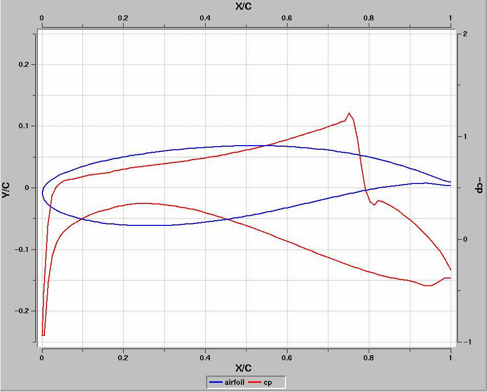
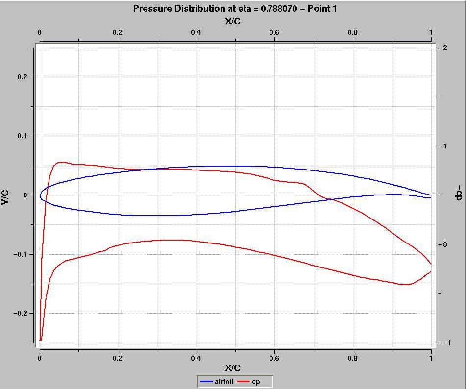
20 (a) Before optimization (b) After optimization Figure 23. Sectional pressure at = (a) Before optimization (b) After optimization Figure 24 Sectional pressure at =0.4. (a) Before optimization (b) After optimization Figure 25. Sectional pressure at =
21 Figure 26. Business jet configuration after MDO. References 1 Ashely, H., On making things the best- aeronautical uses of optimization, AIAA Aircraft Systems and Technology Conference, AIAA , Ohio, August 1981, pp Dornheim, M. A., Dassault s Falcon 2000: New Big Cabin Twinjet, Aviation Week & Space Technology, March 29, 1993, pp North, D. M., IAI Launches Galaxy into Crowded Market, Aviation Week & Space Technology, September 27, 1993, p Goritschnig, G., Isikveren, A., Lamothe, M., and Munger, E., The evolution of civil aircraft design at Bombardier: A historical perespective, CASI conference proceedings, 2003, pp Gallman, J. W., Madson, M. D., Chandrasekharan, R., Hawke, V., Hinson, M., Saunders, D., Mendoza, D., Reuther, J., Optimization of a transonic business jet wing, 33 rd Aerospace Sciences Meeting and Exhibit, AIAA , January 1995, Reno, pp Gallman, J. W., Reuther, J., Pfeiffer, N., Forrest, W., and Bernstorf, D., Business jet wing design using aerodynamic shape optimization, 34 th Aerospace Sciences Meeting and Exhibit, AIAA , January 1996, Reno, pp Gallman, J. W., Kaul, R., Chandrasekharan, R., and V., Hinson, Optimization of an advanced business jet, Journal of Aircraft, Vol. 34, No. 3, May-June 1997, pp Kelm, R., and Grabietz, M., Aeroelastic effects on the weight of an aircraft in the pre-design phase, SAWE paper 2407, 56 th Annual Conference of Weight Engineers, Bellevue WA, May Kafyeke, F., Abdo, M., Pépin, F., Piperni, P., and Laurendeau, Challenges of aircraft design integration, Reduction of Military Vehicle Acquisition Time and Cost Through Advanced Modeling and Virtual Product Simulation, NATO RTO, Applied Vehicle Technology (AVT) Symposium, MP-89-P-48, Paris, France, April Kroo, I., MDO for large-scale systems, in Multidisciplinary design optimization: State of the Art, N. M. Alexandrov and M. Y. Hussaini, eds., SIAM, 1997, pp Kroo, I., and Manning, V., Collaborative optimization: status and directions, AIAA paper, AIAA , 2000, pp Sobieski, I., and Kroo, I., Collaborative optimization using response surface estimation, 36 th Aerospace Sciences Meeting and Exhibit, AIAA , January 1998, Reno, pp Allwright, S., Technical data management for collaborative multi-discipline optimization, AIAA Paper, AIAA ,
22 14 Altus, S., and Kroo, I., Concurrent wing design and flight-path optimization using optimizer based decomposition, AIAA paper, AIAA , 1998, pp Sobieski, J., and Haftka, R. T., Multidisciplinary aerospace design optimization: survey of recent developments, 34 th AIAA Aerospace Sciences Meeting and Exhibition, AIAA , Reno, Balling, R. J., and Wilkinson, C. A., Execution of multidisciplinary design optimization approaches on common test problems, 6 th AIAA/NASA/ISSMO symposium on Multidisciplinary Analysis and Optimization, AIAA CP, 1996, pp Morris, A. J., and Gantois, K., Combined MDO optimization including drag, mass and manufacturing information, 7 th AIAA/USAF/ISSMO symposium on Multidisciplinary Analysis and Optimization, AIAA , St. Louis, September, 1998, pp Wilkinson, K., Lerner, E., and Taylor, R., Practical design of minimum-weight aircraft structures for strength and flutter requirements, Journal of Aircraft, Vol. 13, No. 8, August, 1976, pp Miller, G. D., Active flexible wing technology, AFWAL-TR , February Miller, G. D., An active flexible wing multi-disciplinary design optimization method, AIAA paper, AIAA CP, 1994, pp Vanderplaats, G. N., Sugimoto, H., and Sprague, C. M., ADS-1: A new general purpose optimization program, AIAA Journal, Vol. 22, No. 10, Vanderplaats, G. N., Numerical optimization techniques for engineering design: with applications, McGraw-Hill Book Company1984, Chaps. 4, 5, 9, Prandtl, L., Applications of modern hydrodynamics to aeronautics, translated as NACA Report 116 (original sources dated ). 24 Jones, R. T., The spanwise distribution of lift for minimum induced drag of wings having given lift and root bending moment, NASA TN-2249, Jones, R. T., and Lasinski, T., Effect of winglets on the induced drag of ideal wing shapes, NASA TM-81230, Kroo, I., A general approach to multiple lifting surface design and analysis, AIAA paper, AIAA , McGeer, T., Wing design for minimum drag with practical constraints, Journal of Aircraft, Vol. 21, Nov. 1984, pp Craig, A., and McLean, J., Spanload optimization for strength designed lifting surfaces, AIAA Paper, AIAA , Wakayama, S., and Kroo, I., Subsonic wing planform design using multidisciplinary optimization, Journal of Aircraft, Vol. 32, No. 4, July-August, 1995, pp Iglesias, S., and Mason, W. H., Optimum spanloads incorporating wing structural weight, First AIAA Aircraft Technology, Integration, and Operations Forum, AIAA , Los Angeles, October 2001, pp Grasmeyer, J.M., Naghshineh, A., Tetrault, P.A., Grossman, B., Haftka, R.T., Kapania, R.K., Mason, W.H., and Schetz, J.A., Multidisciplinary design optimization of a strut-braced wing aircraft with tip-mounted engines, MAD Center Report, MAD , January Gern, F. H., Gundlach, J.F., Ko, A., Naghshineh, A., Sulaeman, E., Tetrault, P.A., Grossman, Kapania, R.K., Mason, W.H., and Schetz, J.A., Multidisciplinary design optimization of a transonic commercial transport with a strut-braced wing, SAE paper , 1999 World Aviation Conference, San Francisco, October, Giesing, J. P., and Wakayama, S., A simple cost related objective function for MDO of transport aircraft, 35 th Aerospace Sciences Meeting and Exhibit, AIAA , Reno, January 1997, pp Johnson, V. S., Minimizing life cycle cost for subsonic commercial aircraft, Journal of Aircraft, Vol. 27, No. 2, February Andersen, G., and Venkayya, V., The roll of conceptual and preliminary design in airframe MDO, AIAA CP, 1996, pp Elliott, W. G., and Leigh, B. R., Aircraft loads methodology for MDO, AIAA paper, AIAA Kolonay, R., Dindar, M., Love, M., and Garza, A., A methodology of large scale computational aeroelasticity for the MDA/MDO environment, 8 th AIAA/NASA/USAF/ISSMO Symposium on MDO, AIAA , September Browman, K., Grandhi, R., Eastep, F., Integrated design of aerodynamics and structures, AIAA/AHS/ASEE Aircraft Design, Systems and Operations Conference, AIAA , Seattle, August Giles, G. L., Equivalent plate analysis of aircraft wing box structures with general planform geometry, Journal of Aircraft, Vol. 23, No. 11, November 1986, pp Brooks, C., and Meyer, E., New aircraft lower wing skin trade study, 36 th AIAA/ASME/ASCE/AHS/ASC Structures, Structural Dynamics and Materials Conference, AIAA , New Orleans, April 1995, pp Butler, R., Lillico, M., Banerjee, J., Patel, M., and Done, G., Sequential use of conceptual MDO and panel sizing methods for aircraft wing design, The Aeronautical Journal, Paper No. 2422, August 1999, pp Lillico, M., Butler, R., Guo, S., and Banerjee, J.R., Aeroelastic optimization of composite wings using the dynamic stiffness method, The Aeronautical Journal, Vol. 101, No. 1002, 1997, pp Butler, R., and Williams, F. W., Optimum design using VICONOPT, a buckling and strength constraint program for prismatic assemblies of anisotropic plates, Computers and Structures, Vol. 43, No. 4, 1992, pp Anderson, M., and Stroud, W., General panel sizing computer code and its application to composite structural panels, AIAA Journal, Vol. 17, No. 8, August 1979, pp
23 45 Isakson, G., Pardo, H., Lerner, E., Venkayya, V., ASOP-3: a program for optimum structural design to satisfy strength and deflection constraints, Journal of Aircraft, Vol. 15, No. 7, July 1978, pp Bushnell, D., and Bushnell, W. D., Minimum-weight design of a stiffened panel via PANDA2 and evaluation of the optimized panel via STAGS, Computers and Structures, Vol. 50, No. 4, 1994, pp Lions, J. L., Optimal Control of Systems Governed by Partial Differential Equations, Springer-Verlag, New York, 1971, Translated by S.K. Mitter. 48 Pironneau, O., Optimal Shape Design for Elliptic Systems, Springer-Verlag, New York, Reuther, J.J., Jameson, A., Alonso, J.J., Rimlinger, M.J., and Saunders, D., Constrained multipoint aerodynamic shape optimization using an adjoint formulation and parallel computers, Part 1 & 2, Journal of Aircraft, Vol. 36, No. 1, January- February 1999, pp Jameson, A., Kim, S., Shankaran, S., Leoviriyakit, K., Aerodynamic shape optimization: Exploring the limits of design, KSAS 1 st International Sessions in 2003 Fall Conference, KSAS 03, Korea, November 2003, pp Jameson, A., Shankaran, S., Martinelli, L., Haimes, B., Aerodynamic shape optimization of complete aircraft configurations using unstructured grids, 42 nd Aerospace Science Meeting, AIAA , Reno, 2004, pp Nemec, M., Zingg, D., Optimization of high-lift configurations using a Newton-Krylov algorithm, 16 th AIAA Computational Fluid Dynamics Conference, AIAA , June 2003, pp Pulliam, T.H., Nemec, M., Holst, T., and Zingg, D., Comparison of evolutionary (genetic) algorithm and adjoint methods for multi-objective viscous airfoil optimization, 41 st Aerospace Sciences Meeting, AIAA , January 2003, pp Liu, P., and Zingg, D., Comparison of optimization algorithms applied to aerodynamic design, 42 nd Aerospace Science Meeting, AIAA , Reno, 2004, pp Kafyeke, F., Abdo, M., Pépin, F., Piperni, P., Laurendeau, E., Challenges of Aircraft Design Integration, 3 rd International Workshop on Numerical Simulation Technology for Design of the Next Generation Supersonic Civil Transport, Tokyo, Japan, December Ndiaye, A., Trépanier, J.Y., Guibault, F., Ozell, B., Mahdavi, B., Database Requirements for an MDO Framework, Conference of the Canadian CFD Society, Montreal, June Chen, B., Bouhemhem, D., Ndiaye, A., Guibault, F., Ozell, B., Trépanier, J.Y., An Object-Oriented Application Framework for Distributed Engineering Analysis and Optimization, 15 th Annual International Symposium on High Performance Computing Systems and Applications, Windsor University, Ontario, Canada, June Kafyeke, F. and Piperni, P. Applications of KTRAN Transonic Small Disturbance code to the Challenger Business Jet Configuration with Winglets, SAE Paper , October Piperni, P. and Kafyeke, F., "Applications of the KTRAN Transonic Small Disturbance Code to the Complete CF-18 Aircraft with Stores," Canadian Aeronautics and Space Institute (CASI) Journal, Vol. 36, No. 3, September Piperni, P. and Stokoe, K., "Estimation of store interference loads using transonic small disturbance Theory and Influence Function Method," AGARD-CP-570, February Piperni, P., Patel, K., and Kafyeke, F., The prediction of aircraft trim drag in transonic flight using CFD, 46 th Annual CASI Conference, Montreal, May Zhu Z., Laurendeau E., Mokhtarian F., Cell-Centered and Cell-Vertex algorithm for complex flow configurations, 8 th Annual Conference of the CFD Society of Canada, Montreal, June 11-13, Sadri R., Leblond D., Piperni, P., Coupling of a wing inverse design code to a Euler/Navier-Stokes flow solver using mesh movement capabilities, CASI 50 th Annual General Meeting and Conference, Montreal, April Abdo, M., Sadri, R., and Piperni, P., Multi-Disciplinary Optimization of Wings, Bombardier Report, MAA Abdo, M., Piperni, P. and Kafyeke, F. Conceptual design of stringer stiffened compression panels, CASI 16 th Aerospace Structures & Materials Symposium, Abdo, M., L Heureux, R., Pépin, F., and Kafyeke, F., Equivalent finite element wing structural models used for aerodynamics-structures interaction, CASI 16 th Aerospace Structures & Materials Symposium, Abdo, M., Kafyeke, F. and Pépin, F., Transonic aerodynamics of flexible wings, CASI 48 th Annual Conference Proceedings, Abdo, M. and Pépin, F., Transonic Aerodynamics of Flexible Wings, Bombardier Report, MAA Abdo, M., Leblond, D., Sadri, R., and Piperni, P., Multi-Disciplinary Wing Optimization Methods, Bombardier Report, MAA Reymond, M. and Miller, M. MSC/NASTRAN, Quick Reference Guide, Version 68, General Aviation Synthesis Program- GASP, NASA CR , Cosmic Program ARC Wakayama, S and Kroo, I., Subsonic wing planform design using multidisciplinary optimization, Journal of Aircraft, Vol. 32, No. 4, July-August Kuhn, P., Peterson, J., and Levin, L., A summary of diagonal tension, Part I- methods of analysis, NACA Technical Note Farrar, D. J., The design of compression structures for minimum weight, Journal of The Royal Aeronautical Society, November 1949, pp Isikveren, A., Identifying economically optimum flight techniques of transport aircraft, Journal of Aircraft, Vol. 39, No. 4, July-August 2002, pp Isikveren, A., Parametric modeling techniques in industrial conceptual transport aircraft design, 2003 World Aviation Congress, Montreal, SAE Paper , September
FURTHER ANALYSIS OF MULTIDISCIPLINARY OPTIMIZED METALLIC AND COMPOSITE JETS
 FURTHER ANALYSIS OF MULTIDISCIPLINARY OPTIMIZED METALLIC AND COMPOSITE JETS Antoine DeBlois Advanced Aerodynamics Department Montreal, Canada 6th Research Consortium for Multidisciplinary System Design
Multidisciplinary Design Optimization of a Truss-Braced Wing Aircraft with Tip-Mounted Engines
 Multidisciplinary Design Optimization of a Truss-Braced Wing Aircraft with Tip-Mounted Engines NASA Design MAD Center Advisory Board Meeting, November 14, 1997 Students: J.M. Grasmeyer, A. Naghshineh-Pour,
Environmentally Focused Aircraft: Regional Aircraft Study
 Environmentally Focused Aircraft: Regional Aircraft Study Sid Banerjee Advanced Design Product Development Engineering, Aerospace Bombardier International Workshop on Aviation and Climate Change May 18-20,
Evolution of MDO at Bombardier Aerospace
 Evolution of MDO at Bombardier Aerospace 6 th Research Consortium for Multidisciplinary System Design Workshop Ann Arbor, Michigan July 26 th - 27 th, 2011 Pat Piperni MDO Project Manager Bombardier Aerospace
ADVENT. Aim : To Develop advanced numerical tools and apply them to optimisation problems in engineering. L. F. Gonzalez. University of Sydney
 ADVENT ADVanced EvolutioN Team University of Sydney L. F. Gonzalez E. J. Whitney K. Srinivas Aim : To Develop advanced numerical tools and apply them to optimisation problems in engineering. 1 2 Outline
SILENT SUPERSONIC TECHNOLOGY DEMONSTRATION PROGRAM
 25 TH INTERNATIONAL CONGRESS OF THE AERONAUTICAL SCIENCES SILENT SUPERSONIC TECHNOLOGY DEMONSTRATION PROGRAM Akira Murakami* *Japan Aerospace Exploration Agency Keywords: Supersonic, Flight experiment,
Overview and Team Composition
 Overview and Team Composition Aerodynamics and MDO Andy Ko Joel Grasmeyer* John Gundlach IV* Structures Dr. Frank H. Gern Amir Naghshineh-Pour* Aeroelasticity Erwin Sulaeman CFD and Interference Drag Philippe-Andre
'A CASE OF SUCCESS: MDO APPLIED ON THE DEVELOPMENT OF EMBRAER 175 ENHANCED WINGTIP' Cavalcanti J., London P., Wallach R., Ciloni P.
 'A CASE OF SUCCESS: MDO APPLIED ON THE DEVELOPMENT OF EMBRAER 175 ENHANCED WINGTIP' Cavalcanti J., London P., Wallach R., Ciloni P. EMBRAER, Brazil Keywords: Aircraft design, MDO, Embraer 175, Wingtip
AIRCRAFT CONCEPTUAL DESIGN WITH NATURAL LAMINAR FLOW
 !! 27 TH INTERNATIONAL CONGRESS OF THE AERONAUTICAL SCIENCES AIRCRAFT CONCEPTUAL DESIGN WITH NATURAL LAMINAR FLOW Eric Allison*, Ilan Kroo**, Peter Sturdza*, Yoshifumi Suzuki*, Herve Martins-Rivas* *Desktop
Multidisciplinary Design Optimization of a Strut-Braced Wing Transonic Transport
 Multidisciplinary Design Optimization of a Strut-Braced Wing Transonic Transport John F. Gundlach IV Masters Thesis Defense June 7,1999 Acknowledgements NASA LMAS Student Members Joel Grasmeyer Phillipe-Andre
FLIGHT TEST RESULTS AT TRANSONIC REGION ON SUPERSONIC EXPERIMENTAL AIRPLANE (NEXST-1)
") 26 TH INTERNATIONAL CONGRESS OF THE AERONAUTICAL SCIENCES FLIGHT TEST RESULTS AT TRANSONIC REGION ON SUPERSONIC EXPERIMENTAL AIRPLANE (NEXST-1) Dong-Youn Kwak*, Hiroaki ISHIKAWA**, Kenji YOSHIDA* *Japan
26 TH INTERNATIONAL CONGRESS OF THE AERONAUTICAL SCIENCES FLIGHT TEST RESULTS AT TRANSONIC REGION ON SUPERSONIC EXPERIMENTAL AIRPLANE (NEXST-1) Dong-Youn Kwak*, Hiroaki ISHIKAWA**, Kenji YOSHIDA* *Japan
Modeling, Structural & CFD Analysis and Optimization of UAV
 Modeling, Structural & CFD Analysis and Optimization of UAV Dr Lazaros Tsioraklidis Department of Unified Engineering InterFEA Engineering, Tantalou 7 Thessaloniki GREECE Next Generation tools for UAV
Rotorcraft Gearbox Foundation Design by a Network of Optimizations
 13th AIAA/ISSMO Multidisciplinary Analysis Optimization Conference 13-15 September 2010, Fort Worth, Texas AIAA 2010-9310 Rotorcraft Gearbox Foundation Design by a Network of Optimizations Geng Zhang 1
Nacelle Chine Installation Based on Wind-Tunnel Test Using Efficient Global Optimization
 Trans. Japan Soc. Aero. Space Sci. Vol. 51, No. 173, pp. 146 150, 2008 Nacelle Chine Installation Based on Wind-Tunnel Test Using Efficient Global Optimization By Masahiro KANAZAKI, 1Þ Yuzuru YOKOKAWA,
Preliminary Design of a Mach 6 Configuration using MDO
 Preliminary Design of a Mach 6 Configuration using MDO Robert Dittrich and José M.A. Longo German Aerospace Center (DLR) - Institute of Aerodynamics and Flow Technology Lilienthalplatz 7, 38108 Braunschweig,
AIRCRAFT DESIGN SUBSONIC JET TRANSPORT
 AIRCRAFT DESIGN SUBSONIC JET TRANSPORT Analyzed by: Jin Mok Professor: Dr. R.H. Liebeck Date: June 6, 2014 1 Abstract The purpose of this report is to design the results of a given specification and to
STRUCTURAL DESIGN AND ANALYSIS OF ELLIPTIC CYCLOCOPTER ROTOR BLADES
 16 TH INTERNATIONAL CONFERENCE ON COMPOSITE MATERIALS STRUCTURAL DESIGN AND ANALYSIS OF ELLIPTIC CYCLOCOPTER ROTOR BLADES In Seong Hwang 1, Seung Yong Min 1, Choong Hee Lee 1, Yun Han Lee 1 and Seung Jo
MSC/Flight Loads and Dynamics Version 1. Greg Sikes Manager, Aerospace Products The MacNeal-Schwendler Corporation
 MSC/Flight Loads and Dynamics Version 1 Greg Sikes Manager, Aerospace Products The MacNeal-Schwendler Corporation Douglas J. Neill Sr. Staff Engineer Aeroelasticity and Design Optimization The MacNeal-Schwendler
(1) Keywords: CFD, helicopter fuselage, main rotor, disc actuator
 Keywords: CFD, helicopter fuselage, main rotor, disc actuator") SIMULATION OF FLOW AROUND FUSELAGE OF HELICOPTER USING ACTUATOR DISC THEORY A.S. Batrakov *, A.N. Kusyumov *, G. Barakos ** * Kazan National Research Technical University n.a. A.N.Tupolev, ** School of
SIMULATION OF FLOW AROUND FUSELAGE OF HELICOPTER USING ACTUATOR DISC THEORY A.S. Batrakov *, A.N. Kusyumov *, G. Barakos ** * Kazan National Research Technical University n.a. A.N.Tupolev, ** School of
Development of an Advanced Rotorcraft Preliminary Design Framework
 134 Int l J. of Aeronautical & Space Sciences, Vol. 10, No. 2, November 2009 Development of an Advanced Rotorcraft Preliminary Design Framework Jaehoon Lim* and SangJoon Shin** School of Mechanical and
DESIGN AND PERFORMANCE TEST OF A TWIN- FUSELAGE CONFIGURATION SOLAR-POWERED UAV
 DESIGN AND PERFORMANCE TEST OF A TWIN- FUSELAGE CONFIGURATION SOLAR-POWERED UAV Xian-Zhong GAO*, Zhong-Xi HOU*, Zheng GUO* Xiao-Qian CHEN* *College of Aerospace Science and Engineering, National University
Primary control surface design for BWB aircraft
 Primary control surface design for BWB aircraft 4 th Symposium on Collaboration in Aircraft Design 2014 Dr. ir. Mark Voskuijl, ir. Stephen M. Waters, ir. Crispijn Huijts Challenge Multiple redundant control
Simulating Rotary Draw Bending and Tube Hydroforming
 Abstract: Simulating Rotary Draw Bending and Tube Hydroforming Dilip K Mahanty, Narendran M. Balan Engineering Services Group, Tata Consultancy Services Tube hydroforming is currently an active area of
On-Demand Mobility Electric Propulsion Roadmap
 On-Demand Mobility Electric Propulsion Roadmap Mark Moore, ODM Senior Advisor NASA Langley Research Center EAA AirVenture, Oshkosh July 22, 2015 NASA Distributed Electric Propulsion Research Rapid, early
UNCLASSIFIED FY 2017 OCO. FY 2017 Base
 Exhibit R-2, RDT&E Budget Item Justification: PB 2017 Air Force Date: February 2016 3600: Research, Development, Test & Evaluation, Air Force / BA 2: Applied Research COST ($ in Millions) Prior Years FY
MODELING SUSPENSION DAMPER MODULES USING LS-DYNA
 MODELING SUSPENSION DAMPER MODULES USING LS-DYNA Jason J. Tao Delphi Automotive Systems Energy & Chassis Systems Division 435 Cincinnati Street Dayton, OH 4548 Telephone: (937) 455-6298 E-mail: Jason.J.Tao@Delphiauto.com
Effect of concave plug shape of a control valve on the fluid flow characteristics using computational fluid dynamics
 Effect of concave plug shape of a control valve on the fluid flow characteristics using computational fluid dynamics Yasser Abdel Mohsen, Ashraf Sharara, Basiouny Elsouhily, Hassan Elgamal Mechanical Engineering
blended wing body aircraft for the
 Feasibility study of a nuclear powered blended wing body aircraft for the Cruiser/Feeder eede concept cept G. La Rocca - TU Delft 11 th European Workshop on M. Li - TU Delft Aircraft Design Education Linköping,
The Sonic Cruiser A Concept Analysis
 International Symposium "Aviation Technologies of the XXI Century: New Aircraft Concepts and Flight Simulation", 7-8 May 2002 Aviation Salon ILA-2002, Berlin The Sonic Cruiser A Concept Analysis Dr. Martin
MADCenterAdvisory Board Meeting November 13, 1998
 MADCenterAdvisory Board Meeting November 13, 1998 Overview and Team Composition Aerodynamics and MDO John Gundlach IV Andy Ko Structures Amir Naghshineh-Pour Dr. Frank H. Gern Aeroelasticity Erwin Sulaeman
The Effects of Damage and Uncertainty on the Aeroelastic / Aeroservoelastic Behavior and Safety of Composite Aircraft
 The Effects of Damage and Uncertainty on the Aeroelastic / Aeroservoelastic Behavior and Safety of Composite Aircraft Presented by Professor Eli Livne Department of Aeronautics and Astronautics University
Jay Gundlach AIAA EDUCATION SERIES. Manassas, Virginia. Joseph A. Schetz, Editor-in-Chief. Blacksburg, Virginia. Aurora Flight Sciences
 Jay Gundlach Aurora Flight Sciences Manassas, Virginia AIAA EDUCATION SERIES Joseph A. Schetz, Editor-in-Chief Virginia Polytechnic Institute and State University Blacksburg, Virginia Published by the
DEVELOPMENT OF A CARGO AIRCRAFT, AN OVERVIEW OF THE PRELIMINARY AERODYNAMIC DESIGN PHASE
 ICAS 2000 CONGRESS DEVELOPMENT OF A CARGO AIRCRAFT, AN OVERVIEW OF THE PRELIMINARY AERODYNAMIC DESIGN PHASE S. Tsach, S. Bauminger, M. Levin, D. Penn and T. Rubin Engineering center Israel Aircraft Industries
Methodology for Distributed Electric Propulsion Aircraft Control Development with Simulation and Flight Demonstration
 1 Methodology for Distributed Electric Propulsion Aircraft Control Development with Simulation and Flight Demonstration Presented by: Jeff Freeman Empirical Systems Aerospace, Inc. jeff.freeman@esaero.com,
Annual Report Summary Green Regional Aircraft (GRA) The Green Regional Aircraft ITD
 The Green Regional Aircraft ITD") Annual Report 2011 - Summary Green Regional Aircraft (GRA) The Green Regional Aircraft ITD Green Regional Aircraft ITD is organised so as to: 1. develop the most promising mainstream technologies regarding
Annual Report 2011 - Summary Green Regional Aircraft (GRA) The Green Regional Aircraft ITD Green Regional Aircraft ITD is organised so as to: 1. develop the most promising mainstream technologies regarding
Design Considerations for Stability: Civil Aircraft
 Design Considerations for Stability: Civil Aircraft From the discussion on aircraft behavior in a small disturbance, it is clear that both aircraft geometry and mass distribution are important in the design
Wing Planform Optimization of a Transport Aircraft
 22nd Applied Aerodynamics Conference and Exhibit 16-19 August 2004, Providence, Rhode Island AIAA 2004-5191 Wing Planform Optimization of a Transport Aircraft Paulo Ferrucio Rosin Bento Silva de Mattos
Influence of Cylinder Bore Volume on Pressure Pulsations in a Hermetic Reciprocating Compressor
 Purdue University Purdue e-pubs International Compressor Engineering Conference School of Mechanical Engineering 2014 Influence of Cylinder Bore Volume on Pressure Pulsations in a Hermetic Reciprocating
Analysis Methods for Skewed Structures. Analysis Types: Line girder model Crossframe Effects Ignored
 Analysis Methods for Skewed Structures D Finite Element Model Analysis Types: Line girder model Crossframe Effects Ignored MDX Merlin Dash BSDI StlBridge PC-BARS Others Refined model Crossframe Effects
CFD Investigation of Influence of Tube Bundle Cross-Section over Pressure Drop and Heat Transfer Rate
 CFD Investigation of Influence of Tube Bundle Cross-Section over Pressure Drop and Heat Transfer Rate Sandeep M, U Sathishkumar Abstract In this paper, a study of different cross section bundle arrangements
Aircraft Design Conceptual Design
 Université de Liège Département d Aérospatiale et de Mécanique Aircraft Design Conceptual Design Ludovic Noels Computational & Multiscale Mechanics of Materials CM3 http://www.ltas-cm3.ulg.ac.be/ Chemin
EFFECT OF SURFACE ROUGHNESS ON PERFORMANCE OF WIND TURBINE
 Chapter-5 EFFECT OF SURFACE ROUGHNESS ON PERFORMANCE OF WIND TURBINE 5.1 Introduction The development of modern airfoil, for their use in wind turbines was initiated in the year 1980. The requirements
OPTIMAL MISSION ANALYSIS ACCOUNTING FOR ENGINE AGING AND EMISSIONS
 OPTIMAL MISSION ANALYSIS ACCOUNTING FOR ENGINE AGING AND EMISSIONS M. Kelaidis, N. Aretakis, A. Tsalavoutas, K. Mathioudakis Laboratory of Thermal Turbomachines National Technical University of Athens
ADVANCED STRUCTURAL OPTIMIZATION UNDER CONSIDERATION OF COST TRACKING
 ADVANCED STRUCTURAL OPTIMIZATION UNDER CONSIDERATION OF COST TRACKING D. Zell (1), T. Link (1), S. Bickelmaier (1), J. Albinger (1) S. Weikert (2), F. Cremaschi (2), A. Wiegand (2), (1) MT Aerospace AG,
Designing evtol for the Mission NDARC NASA Design and Analysis of Rotorcraft. Wayne Johnson From VTOL to evtol Workshop May 24, 2018
 Designing evtol for the Mission NDARC NASA Design and Analysis of Rotorcraft Wayne Johnson From VTOL to evtol Workshop May 24, 2018 1 Conceptual Design of evtol Aircraft Conceptual design Define aircraft
CFD Analysis of Winglets at Low Subsonic Flow
 , July 6-8, 2011, London, U.K. CFD Analysis of Winglets at Low Subsonic Flow M. A Azlin, C.F Mat Taib, S. Kasolang and F.H Muhammad Abstract A winglet is a device attached at the wingtip, used to improve
General Dynamics F-16 Fighting Falcon
 General Dynamics F-16 Fighting Falcon http://www.globalsecurity.org/military/systems/aircraft/images/f-16c-19990601-f-0073c-007.jpg Adam Entsminger David Gallagher Will Graf AOE 4124 4/21/04 1 Outline
CONCEPTUAL DESIGN OF ECOLOGICAL AIRCRAFT FOR COMMUTER AIR TRANSPORTATION
 26 TH INTERNATIONAL CONGRESS OF THE AERONAUTICAL SCIENCES CONCEPTUAL DESIGN OF ECOLOGICAL AIRCRAFT FOR COMMUTER AIR TRANSPORTATION Yasuhiro TANI, Tomoe YAYAMA, Jun-Ichiro HASHIMOTO and Shigeru ASO Department
Design and Test of Transonic Compressor Rotor with Tandem Cascade
 Proceedings of the International Gas Turbine Congress 2003 Tokyo November 2-7, 2003 IGTC2003Tokyo TS-108 Design and Test of Transonic Compressor Rotor with Tandem Cascade Yusuke SAKAI, Akinori MATSUOKA,
Overview of Helicopter HUMS Research in DSTO Air Vehicles Division
 AIAC-12 Twelfth Australian International Aerospace Congress Overview of Helicopter HUMS Research in DSTO Air Vehicles Division Dr Ken Anderson 1 Chief Air Vehicles Division DSTO Australia Abstract: This
Environmental issues for a supersonic business jet
 Environmental issues for a supersonic business jet ICAS Workshop 2009 28th, Sepe September 2009 ICAS 2009 - Sept 2009 - Page 1 Introduction Supersonic Transport Aircraft in 2009 : Potential strong interest
STIFFNESS CHARACTERISTICS OF MAIN BEARINGS FOUNDATION OF MARINE ENGINE
 Journal of KONES Powertrain and Transport, Vol. 23, No. 1 2016 STIFFNESS CHARACTERISTICS OF MAIN BEARINGS FOUNDATION OF MARINE ENGINE Lech Murawski Gdynia Maritime University, Faculty of Marine Engineering
International Journal of Scientific & Engineering Research, Volume 5, Issue 7, July-2014 ISSN
 ISSN 9-5518 970 College of Engineering Trivandrum Department of Mechanical Engineering arundanam@gmail.com, arjunjk91@gmail.com Abstract This paper investigates the performance of a shock tube with air
Using ABAQUS in tire development process
 Using ABAQUS in tire development process Jani K. Ojala Nokian Tyres plc., R&D/Tire Construction Abstract: Development of a new product is relatively challenging task, especially in tire business area.
Keywords: Supersonic Transport, Sonic Boom, Low Boom Demonstration
 Blucher Mechanical Engineering Proceedings May 2014, vol. 1, num. 1 www.proceedings.blucher.com.br/evento/10wccm LOW-SONIC-BOOM CONCEPT DEMONSTRATION IN SILENT SUPERSONIC RESEARCH PROGRAM AT JAXA Yoshikazu
INTRODUCTION. Research & Reviews: Journal of Engineering and Technology. Research Article
 Aircraft Fuel Manifold Design Substantiation and Additive Manufacturing Technique Assessment Using Finite Element Analysis Prasanna ND, Balasubramanya HS, Jyothilakshmi R*, J Sharana Basavaraja and Sachin
Industrial Use of EsDs ETP4HPC Workshop 22 June 2017 Frankfurt DLR CFD Solver TAU & Flucs for external Aerodynamic
 Industrial Use of EsDs ETP4HPC Workshop 22 June 2017 Frankfurt DLR CFD Solver TAU & Flucs for external Aerodynamic Thomas Gerhold Institute of Aerodynamics and Flow Technology German Aerospace Center (DLR)
Load Analysis and Multi Body Dynamics Analysis of Connecting Rod in Single Cylinder 4 Stroke Engine
 IJSRD - International Journal for Scientific Research & Development Vol. 3, Issue 08, 2015 ISSN (online): 2321-0613 Load Analysis and Multi Body Dynamics Analysis of Connecting Rod in Single Cylinder 4
AE 451 Aeronautical Engineering Design Final Examination. Instructor: Prof. Dr. Serkan ÖZGEN Date:
 Instructor: Prof. Dr. Serkan ÖZGEN Date: 11.01.2012 1. a) (8 pts) In what aspects an instantaneous turn performance is different from sustained turn? b) (8 pts) A low wing loading will always increase
Effect of Stator Shape on the Performance of Torque Converter
 16 th International Conference on AEROSPACE SCIENCES & AVIATION TECHNOLOGY, ASAT - 16 May 26-28, 2015, E-Mail: asat@mtc.edu.eg Military Technical College, Kobry Elkobbah, Cairo, Egypt Tel : +(202) 24025292
MARINE FOUR-STROKE DIESEL ENGINE CRANKSHAFT MAIN BEARING OIL FILM LUBRICATION CHARACTERISTIC ANALYSIS
 POLISH MARITIME RESEARCH Special Issue 2018 S2 (98) 2018 Vol. 25; pp. 30-34 10.2478/pomr-2018-0070 MARINE FOUR-STROKE DIESEL ENGINE CRANKSHAFT MAIN BEARING OIL FILM LUBRICATION CHARACTERISTIC ANALYSIS
Multidisciplinary Design Optimization for a Blended Wing Body Transport Aircraft with Distributed Propulsion
 Multidisciplinary Design Optimization for a Blended Wing Body Transport Aircraft with Distributed Propulsion Leifur Thor Leifsson, Andy Ko, William H. Mason, Joseph A. Schetz, Raphael T. Haftka, and Bernard
Use of Flow Network Modeling for the Design of an Intricate Cooling Manifold
 Use of Flow Network Modeling for the Design of an Intricate Cooling Manifold Neeta Verma Teradyne, Inc. 880 Fox Lane San Jose, CA 94086 neeta.verma@teradyne.com ABSTRACT The automatic test equipment designed
Abaqus Technology Brief. Automobile Roof Crush Analysis with Abaqus
 Abaqus Technology Brief Automobile Roof Crush Analysis with Abaqus TB-06-RCA-1 Revised: April 2007. Summary The National Highway Traffic Safety Administration (NHTSA) mandates the use of certain test procedures
Towards the Optimisation of. Adaptive Aeroelastic Structures
 Towards the Optimisation of Jonathan Cooper Mike Amprikidis, Vijaya Hodere, Gareth Vio School of Mechanical, Aerospace and Civil Engineering University of Manchester ERCOFTAC 6th April 2006 Contents Introduction
AEROELASTIC TAILORING OF THE COMPOSITE WING STRUCTURE VIA SHAPE FUNCTION APPROACH Wenmin Qian 1 and Jie Zeng 1
 2 st International Conference on Composite Materials Xi an, 2-25 th August 27 AEROELASTIC TAILORING OF THE COMPOSITE WING STRUCTURE VIA SHAPE FUNCTION APPROACH Wenmin Qian and Jie Zeng Beijing Key Laboratory
Vehicle Aerodynamics Subscription Development of Numerical Simulation Method of Flow Around Automobile Using Meshfree Method
 Vehicle Aerodynamics Subscription 2005-01-0544 Development of Numerical Simulation Method of Flow Around Automobile Using Meshfree Method 2005-01-0545 A Downforce Optimization Study for a Racing Car Shape
If structures, when exposed to an airstream were to remain perfectly rigid, aeroelastic problems would not exist.
 1. Introduction In the development of modern aircraft, aeroelastic problems have far-reaching effects upon structural and aerodynamic design. Aeroelastic effects are a result of the mutual interaction
Transverse Distribution Calculation and Analysis of Strengthened Yingjing Bridge
 Modern Applied Science; Vol. 8, No. 3; 4 ISSN 93-844 E-ISSN 93-85 Published by Canadian Center of Science and Education Transverse Distribution Calculation and Analysis of Strengthened Yingjing Bridge
INVESTIGATION OF HEAT TRANSFER CHARACTERISTICS OF CIRCULAR AND DIAMOND PILLARED VANE DISC BRAKE ROTOR USING CFD
 SDRP JOURNAL OF NANOTECHNOLOGY & MATERIAL SCIENCE. INVESTIGATION OF HEAT TRANSFER CHARACTERISTICS OF CIRCULAR AND DIAMOND PILLARED VANE DISC BRAKE ROTOR USING CFD Research AUTHOR: A.RAJESH JUNE 2017 1
INVESTIGATION OF ICING EFFECTS ON AERODYNAMIC CHARACTERISTICS OF AIRCRAFT AT TSAGI
 INVESTIGATION OF ICING EFFECTS ON AERODYNAMIC CHARACTERISTICS OF AIRCRAFT AT TSAGI Andreev G.T., Bogatyrev V.V. Central AeroHydrodynamic Institute (TsAGI) Abstract Investigation of icing effects on aerodynamic
ECO-CARGO AIRCRAFT. ISSN: International Journal of Science, Engineering and Technology Research (IJSETR) Volume 1, Issue 2, August 2012
 Volume 1, Issue 2, August 2012") ECO-CARGO AIRCRAFT Vikrant Goyal, Pankhuri Arora Abstract- The evolution in aircraft industry has brought to us many new aircraft designs. Each and every new design is a step towards a greener tomorrow.
ECO-CARGO AIRCRAFT Vikrant Goyal, Pankhuri Arora Abstract- The evolution in aircraft industry has brought to us many new aircraft designs. Each and every new design is a step towards a greener tomorrow.
HELICOPTER TAIL ROTOR ANALYSIS: EXPERIENCE IN AGUSTA WITH ADAMS
 HELICOPTER TAIL ROTOR ANALYSIS: EXPERIENCE IN AGUSTA WITH ADAMS Bianchi F., Agusta Sp.a. Via G.Agusta, 520 - Cascina Costa di Samarate,Varese - Italy - e-mail: atr@agusta.it Abstract The purpose of the
Team 2. AAE451 System Requirements Review. Chad Carmack Aaron Martin Ryan Mayer Jake Schaefer Abhi Murty Shane Mooney
 Team 2 AAE451 System Requirements Review Chad Carmack Aaron Martin Ryan Mayer Jake Schaefer Abhi Murty Shane Mooney Ben Goldman Russell Hammer Donnie Goepper Phil Mazurek John Tegah Chris Simpson Outline
Multibody Dynamics Simulations with Abaqus from SIMULIA
 Multibody Dynamics Simulations with Abaqus from SIMULIA 8.5.2008 Martin Kuessner Martin.KUESSNER@3ds.com Abaqus Deutschland GmbH 2 One Company, First Class Brands 3D MCAD Virtual Product Virtual Testing
FLUIDIC THRUST VECTORING NOZZLES
 FLUIDIC THRUST VECTORING NOZZLES J.J. Isaac and C. Rajashekar Propulsion Division National Aerospace Laboratories (Council of Scientific & Industrial Research) Bangalore 560017, India April 2014 SUMMARY
Preface. Acknowledgments. List of Tables. Nomenclature: organizations. Nomenclature: acronyms. Nomenclature: main symbols. Nomenclature: Greek symbols
 Contents Preface Acknowledgments List of Tables Nomenclature: organizations Nomenclature: acronyms Nomenclature: main symbols Nomenclature: Greek symbols Nomenclature: subscripts/superscripts Supplements
Multidisciplinary System Design Optimization (MSDO)
") Multidisciplinary System Design Optimization (MSDO) Multidisciplinary Design and Analysis Problem Formulation Lecture 2 9 February 2004 Karen Willcox 1 Today s Topics MDO definition MDO disciplines Optimization
Multidisciplinary System Design Optimization (MSDO) Multidisciplinary Design and Analysis Problem Formulation Lecture 2 9 February 2004 Karen Willcox 1 Today s Topics MDO definition MDO disciplines Optimization
MIKLOS Cristina Carmen, MIKLOS Imre Zsolt UNIVERSITY POLITEHNICA TIMISOARA FACULTY OF ENGINEERING HUNEDOARA ABSTRACT:
 1 2 THEORETICAL ASPECTS ABOUT THE ACTUAL RESEARCH CONCERNING THE PHYSICAL AND MATHEMATICAL MODELING CATENARY SUSPENSION AND PANTOGRAPH IN ELECTRIC RAILWAY TRACTION MIKLOS Cristina Carmen, MIKLOS Imre Zsolt
AE 451 Aeronautical Engineering Design I Estimation of Critical Performance Parameters. Prof. Dr. Serkan Özgen Dept. Aerospace Engineering Fall 2015
 AE 451 Aeronautical Engineering Design I Estimation of Critical Performance Parameters Prof. Dr. Serkan Özgen Dept. Aerospace Engineering Fall 2015 Airfoil selection The airfoil effects the cruise speed,
FINITE ELEMENT SIMULATION OF SHOT PEENING AND STRESS PEEN FORMING
 FINITE ELEMENT SIMULATION OF SHOT PEENING AND STRESS PEEN FORMING H.Y. Miao 1, C. Perron 1, M. Lévesque 2 1. Aerospace Manufacturing Technology Center, National Research Council Canada,5154 av. Decelles,
A Joint DLR-ONERA Contribution to CFD-based Investigations of Unconventional Empennages for Future Civil Transport Aircraft
 A Joint DLR-ONERA Contribution to CFD-based Investigations of Unconventional Empennages for Future Civil Transport Aircraft Gérald CARRIER 1 and Lutz GEBHARDT 2 1 ONERA, Applied Aerodynamics Department
Aeronautical Engineering Design II Sizing Matrix and Carpet Plots. Prof. Dr. Serkan Özgen Dept. Aerospace Engineering Spring 2014
 Aeronautical Engineering Design II Sizing Matrix and Carpet Plots Prof. Dr. Serkan Özgen Dept. Aerospace Engineering Spring 2014 Empty weight estimation and refined sizing Empty weight of the airplane
DESIGN INVESTIGATION OF VARIABLE - CAMBER FLAPS FOR HIGH-SUBSONIC AIRLINERS
 ICAS 2000 CONGRESS DESIGN INVESTIGATION OF VARIABLE - CAMBER FLAPS J P Fielding, College of Aeronautics, Cranfield University Bedford, MK43 0AL, United Kingdom Abstract Fixed-camber wings of current transport
The Effects of Damage and Uncertainty on the Aeroelastic / Aeroservoelastic Behavior and Safety of Composite Aircraft. JAMS Meeting, May
 The Effects of Damage and Uncertainty on the Aeroelastic / Aeroservoelastic Behavior and Safety of Composite Aircraft JAMS Meeting, May 2010 1 JAMS Meeting, May 2010 2 Contributors Department of Aeronautics
The Airplane That Could!
 The Airplane That Could! Critical Design Review December 6 th, 2008 Haoyun Fu Suzanne Lessack Andrew McArthur Nicholas Rooney Jin Yan Yang Yang Agenda Criteria Preliminary Designs Down Selection Features
A Coupled Adjoint-Based Method for Aeroelastic Design in the Open-Source SU2 Suite
 A Coupled Adjoint-Based Method for Aeroelastic Design in the Open-Source SU2 Suite Rubén Sánchez*, Rafael Palacios imperial.ac.uk/aeroelastics Airbus DiPaRT 2017, 22 November 2017, Bristol, UK Optimal
Chapter 11: Flow over bodies. Lift and drag
 Chapter 11: Flow over bodies. Lift and drag Objectives Have an intuitive understanding of the various physical phenomena such as drag, friction and pressure drag, drag reduction, and lift. Calculate the
Multidisciplinary System Design Optimization (MSDO)
") Multidisciplinary System Design Optimization (MSDO) Problem Formulation Lecture 2 Anas Alfaris 1 Today s Topics MDO definition Optimization problem formulation MDO in the design process MDO challenges
Multidisciplinary System Design Optimization (MSDO) Problem Formulation Lecture 2 Anas Alfaris 1 Today s Topics MDO definition Optimization problem formulation MDO in the design process MDO challenges
Marc ZELLAT, Driss ABOURI and Stefano DURANTI CD-adapco
 17 th International Multidimensional Engine User s Meeting at the SAE Congress 2007,April,15,2007 Detroit, MI RECENT ADVANCES IN DIESEL COMBUSTION MODELING: THE ECFM- CLEH COMBUSTION MODEL: A NEW CAPABILITY
Multidisciplinary Optimization of Innovative Aircraft using ModelCenter
 Multidisciplinary Optimization of Innovative Aircraft using ModelCenter April 14 th, 2015 Rakesh K. Kapania Mitchell Professor And Joseph A. Schetz Durham Chair in Engineering Department of Aerospace &
Optimization of Seat Displacement and Settling Time of Quarter Car Model Vehicle Dynamic System Subjected to Speed Bump
 Research Article International Journal of Current Engineering and Technology E-ISSN 2277 4106, P-ISSN 2347-5161 2014 INPRESSCO, All Rights Reserved Available at http://inpressco.com/category/ijcet Optimization
IMECE DESIGN OF A VARIABLE RADIUS PISTON PROFILE GENERATING ALGORITHM
 Proceedings of the ASME 2009 International Mechanical Engineering Conference and Exposition ASME/IMECE 2009 November 13-19, 2009, Buena Vista, USA IMECE2009-11364 DESIGN OF A VARIABLE RADIUS PISTON PROFILE
Automatic Aircraft Configuration Redesign The Application of MDO Results to a CAD File
 Automatic Aircraft Configuration Redesign The Application of MDO Results to a CAD File Daniel P. Raymer, Ph.D. Conceptual Research Corp. (www.aircraftdesign.com) MDO2CAD - 1 Overview Integration of MDO
AWIATOR Project Perspectives:
 No SBVGs With SBVGs AWIATOR Project Perspectives: Passive Flow Control on Civil Aircraft Flaps using Sub-Boundary Layer Vortex Generators David Sawyers Aerodynamics R&T Co-ordinator Airbus UK Limited KATnet
Preliminary Design of a LSA Aircraft Using Wind Tunnel Tests
 Preliminary Design of a LSA Aircraft Using Wind Tunnel Tests Norbert ANGI*,1, Angel HUMINIC 1 *Corresponding author 1 Aerodynamics Laboratory, Transilvania University of Brasov, 29 Bulevardul Eroilor,
Design Modification and Optimization of Trolley in an Off-Bearer Mechanism Present In Concrete Block Making Machines
 Design Modification and Optimization of Trolley in an Off-Bearer Mechanism Present In Concrete Block Making Machines Aravindhan. V 1, Anantha Krishnan. P 2 1,2Final Year UG Students, Dept. of Mechanical
NASA Langley Research Center October 16, Strut-Braced Wing Transport NAS DA17
 NASA Langley Research Center October 16, 1998 Introduction Equal basis comparison of advanced conventional, box wing & strut-braced wing transports Parallel study contracts DA16 Box Wing Transport Study
Flugzeugentwurf / Aircraft Design SS Part 35 points, 70 minutes, closed books. Prof. Dr.-Ing. Dieter Scholz, MSME. Date:
 DEPARTMENT FAHRZEUGTECHNIK UND FLUGZEUGBAU Flugzeugentwurf / Aircraft Design SS 2015 Duration of examination: 180 minutes Last Name: Matrikelnummer: First Name: Prof. Dr.-Ing. Dieter Scholz, MSME Date:
AIAA Multidisciplinary Design Optimization of a Strut-Braced Wing Transonic Transport
 AIAA 2000-0420 Multidisciplinary Design Optimization of a Strut-Braced Wing Transonic Transport J.F. Gundlach IV, P-A. Tétrault, F. Gern, A. Nagshineh-Pour, A. Ko, J.A. Schetz, W.H. Mason, R. Kapania,