West Campus Power Plant
|
|
|
- Diane Cameron
- 5 years ago
- Views:
Transcription
1 West Campus Power Plant Tabular Report The University of Iowa Iowa City, IA Final August 2009
2 Executive Summary As new facilities are located on the West Campus, the utility load increases and additional equipment capacity must be added to address the new utility requirements. There is little or no room to expand the existing plant to accommodate additional generation capacity, and a plant located on the West Campus would increase reliability to the utility system. Several steam and electric generation possibilities are available to meet the needs of the West Campus. These possibilities typically include multiple equipment component options. The purpose of this study is to present various equipment component options in tabular format to assist the University of Iowa in determining the most suitable and cost effective configuration for a West Campus Power Plant (WCPP). The component tabs include general descriptions, schedule projections, emissions discussions, layouts, conceptual capital costs, and other considerations associated with the component. The conceptual cost estimates are general in nature and do not account for the following: Relocation of displaced Finkbine Commuter Lot parking to existing Grant Field. Minimizing building profile by locating major equipment in a basement. Using a common stack for the site (single shell, multiple flues). Duct work to a common stack. Structural provisions related to actual soil conditions at proposed site. Disposal of hazardous materials encountered during excavation. Noise abatement provisions. de:mkc:21212\admin_asst\aug-2009\execsum.doc i Stanley Consultants
3 Building costs were estimated based on cost per square foot of building. An assumed value of $245 per square foot was used in an effort to reduce visual impact of the building. An Options Matrix was developed based on discussions with the University of Iowa and is included at the end of this Executive Summary. The matrix uses the breakout conceptual capital cost estimation information from Appendix B to develop specific combustion turbine and boiler project options. This allows an easy way to compare various projects on a relative basis. It should be noted, however, that a more detailed project cost estimate should be performed once a project is selected. Additionally, it should be noted that the tabular format does not lend itself well to combining multiple options and being able to determine whether or not a PSD review is required. In those instances, a separate analysis on the combined project will need to be performed to determine whether or not a PSD review is required. de:mkc:21212\admin_asst\aug-2009\execsum.doc ii Stanley Consultants
4 Table of Contents Executive Summary Section 1 Introduction Section 2 Site and Building Overview Site Location Building and Facility Description Conceptual Capital Costs Section 3 CT Option One (1) 10 MW Combustion Turbine with HRSG Generating Capacity and Fuel Consumption Description Arrangement Schedule Emission Restrictions Conceptual Capital Costs Other Considerations Section 4 CT Option One (1) 23 MW Simple Cycle Combustion Turbine Generating Capacity and Fuel Consumption Description Arrangement Schedule Emission Restrictions Conceptual Capital Costs Other Considerations iii Stanley Consultants
5 Section 5 CT Option One (1) 33 MW Simple Cycle Combustion Turbine Generating Capacity and Fuel Consumption Description Arrangement Schedule Emission Restrictions Conceptual Capital Costs Other Considerations Section 6 CT Option One (1) 33 MW Combustion Turbine with HRSG Generating Capacity and Fuel Consumption Description Arrangement Schedule Emission Restrictions Conceptual Capital Costs Other Considerations Section 7 CT Option One (1) 40 MW Simple Cycle Combustion Turbine Generating Capacity and Fuel Consumption Description Arrangement Schedule Emission Restrictions Conceptual Capital Costs Other Considerations Section 8 Boiler Option psig Package Boiler Generating Capacity and Fuel Consumption Description Arrangement Schedule Emission Restrictions Conceptual Capital Costs Other Considerations Section 9 Boiler Option psig Hurst Boiler Generating Capacity and Fuel Consumption Description Arrangement Schedule Emission Restrictions iv Stanley Consultants
6 Conceptual Capital Costs Other Considerations Section 10 Boiler Option psig Hurst Boiler Generating Capacity and Fuel Consumption Description Arrangement Schedule Conceptual Capital Costs Other Considerations Section 11 Boiler Option psig CFB Boiler Generating Capacity and Fuel Consumption Description Arrangement Schedule Emission Restrictions Conceptual Capital Costs Other Considerations Section 12 ST Option MW Backpressure Steam Turbine Generating Capacity Description Arrangement Schedule Conceptual Capital Costs Other Considerations Section 13 ST Option MW Extraction/Condensing Steam Turbine Generating Capacity Description Arrangement Schedule Conceptual Capital Costs Other Considerations Section 14 Water Treatment Option psig Boiler Cycles General Description Conceptual Capital Costs v Stanley Consultants
7 Section 15 Water Treatment Option Boiler Cycles above 600 psig General Description Conceptual Capital Costs Section 16 Fuel Supply Natural Gas Pipeline Options Solid Biomass Fuel Section 17 Mechanical Distribution System Description Routing Conceptual Cost Estimate Other Considerations Section 18 Sub U Upgrades Description Section kv Electrical Duct Bank Description Routing Conceptual Cost Estimate Other Considerations Section 20 Water Supply and Discharge Description Routing Conceptual Cost Estimate Other Considerations Section 21 Emissions Non-PSD Permit Strategies TOC... D-1 FIGURES Figure 2-1 Tall Plant Profile (Intersection of Mormon Trek Blvd and Highway 6) Figure 2-2 Tall Plant Profile (Intersection of Hawkins Drive and Highway 6) Figure 2-3 Tall Plant Profile (Newton Road East of Carver Hawkeye Arena) Figure 2-4 Short Plant Profile (Intersection of Mormon Trek Blvd and Highway 6) Figure 2-5 Short Plant Profile (Intersection of Hawkins Drive and Highway 6) Figure 2-6 Short Plant Profile (Newton Road East of Carver Hawkeye Arena) Figure 16-1 Natural Gas Supply Option vi Stanley Consultants
8 Figure 16-2 Natural Gas Supply Option Figure 16-3 Natural Gas Supply Option APPENDICES Appendix A Site Plan and Utilities Drawing... A-1 Appendix B Cost Estimate Spreadsheets... B-1 Appendix C Baseline Equipment Emission Projections... C-1 Appendix D OEM Quotes... D-1 vii Stanley Consultants
9 Section 1 Introduction This report breaks out various components associated with constructing a steam and electric generation facility in the Finkbine Commuter Lot on the University of Iowa s west campus. The components are presented in the report in a tabular format. Each tab includes equipment descriptions, arrangements of the equipment, proposed routings for underground utilities (as applicable), conceptual capital cost estimate(s), and commentary on anticipated PSD review requirements for potential emission sources. Several combustion turbine, steam generator, and steam turbine options were investigated. It should be noted that the emission projections made for each tab relate only to the equipment in that tab. The tabular format does not lend itself well to combining multiple options and being able to determine whether or not a PSD review is required. In those instances, a separate analysis on the combined project will need to be performed to determine whether or not a PSD review is required. Conceptual capital cost estimates tallied for various projects should be considered on a relative basis. Once a project is selected, a more detailed project cost estimate should be performed. de:mkc:21212\admin_asst\aug-2009\section1.doc 1-1 Stanley Consultants
10 Section 2 Site and Building Overview Site Location The West Campus Power Plant (WCPP) will be located in the southeast corner of the existing Finkbine Commuter Lot. Displaced parking will be relocated to an alternate location such as the existing Grant Field, which is no longer used for athletic purposes. The Finkbine Commuter Lot is situated on sloped property. Site preparation costs will be minimized by limiting parking lot demolition and grading work. The result will be sloped topography within the boundaries of the WCPP. Vehicle access to the site will be from Finkbine Commuter Drive. Building and Facility Description A conceptual site arrangement for the WCPP is included in Appendix A. Biomass and ash storage silos, truck unloading / loading building, and cooling tower(s), if required, will be located outdoors on the south side of the WCPP building. All other equipment will be housed inside the prefabricated metal building. A multi-level auxiliary bay, that includes a basement and equipment hatch, will be located on the north side of the building for housing balance-of-plant mechanical, electrical, and water treatment equipment. A roll-up door will be located on the east side of the building for equipment access and removal via a 12 feet wide walkway/maintenance aisle. Steam, condensate, potable water, and electrical duct bank utility tie-ins will be located in the northeast corner of the building. Natural gas and plant effluent utility tie-ins will be located on the south side of the building. Adjacent space west of the proposed WCPP will be allocated for future plant expansion. For solid fuel options, a service road will be provided around the south side of the WCPP for biomass delivery, ash removal, and maintenance trucks. Biomass unloading and ash loading will be conducted inside the truck unloading / loading building. de:mkc:21212\admin_asst\aug-2009\section2.doc 2-1 Stanley Consultants
11 The height of the WCPP building depends on equipment heights for the options selected, but could be as short as 50 feet or as tall as 100 feet. Ash and biomass storage silos, if required, will be approximately 90 feet tall. Renderings showing visual impact a taller WCPP building versus a shorter building are included in Figures 2-1 thru 2-6. Each arrangement is shown from three different vantage points. Final stack heights will be determined during the permitting phase. Tall Plant Profile (Intersection of Mormon Trek Blvd and Highway 6) Figure 2-1 Tall Plant Profile (Intersection of Hawkins Drive and Highway 6) Figure 2-2 de:mkc:21212\admin_asst\aug-2009\section2.doc 2-2 Stanley Consultants
12 Tall Plant Profile (Newton Road east of Carver Hawkeye Arena) Figure 2-3 Short Plant Profile (Intersection of Mormon Trek Blvd and Highway 6) Figure 2-4 de:mkc:21212\admin_asst\aug-2009\section2.doc 2-3 Stanley Consultants
13 Short Plant Profile (Intersection of Hawkins Drive and Highway 6) Figure 2-5 Short Plant Profile (Newton Road East of Carver Hawkeye Arena) Figure 2-6 de:mkc:21212\admin_asst\aug-2009\section2.doc 2-4 Stanley Consultants
14 Conceptual Capital Costs A conceptual capital cost estimate for site preparation and parking relocation were developed based on past similar projects and cost estimating references. Cost estimate details for site preparation and parking relocation are included in Table B-2 in Appendix B. The estimated capital cost for site preparation and parking relocation is $1,961,949. de:mkc:21212\admin_asst\aug-2009\section2.doc 2-5 Stanley Consultants
15 Section 3 CT Option 1 One (1) 10 MW Simple Cycle Combustion Turbine and One (1) 10 MW Combustion Turbine with HRSG Generating Capacity and Fuel Consumption This option will use natural gas to produce up to 20 MW of electrical generation and 100 kpph of 165 psig steam for West Campus use. Each combustion turbine will use approximately 118 Mcfh of natural gas at full load operation. The duct burners included with the HRSG will be designed to burn up to 64 Mcfh of fuel for supplemental firing. The maximum fuel consumption rate for this option is approximately 300 Mcfh. Description The following equipment will be included with this option: Two (2) 10 MW (each) axial exhaust combustion turbines. One (1) 100 kpph, 165 psig supplemental fired HRSG. One (1) 500 kw black start gas-fired generator. Three (3) Reciprocating natural gas compressors. One (1) 30,000 gallon condensate storage tank. Refer to Table B-3 in Appendix B for a complete list of equipment. One of the combustion turbines will be used as a simple cycle unit for generating electricity. The other combustion turbine will be coupled to an HRSG and will capable of cogenerating steam and electricity or electricity only via an exhaust gas bypass system. Each combustion turbine will use de:mkc:21212\admin_asst\aug-2009\section3.doc 3-1 Stanley Consultants
16 a stand-alone inlet air chilling system to increase electrical output of the machines when outdoor ambient temperatures are high. The HRSG will be coupled in-line with the axial exhaust combustion turbine. A diverter damper and bypass stack will be included for simple cycle operation. Duct burners will be used to supplement steam generation in the HRSG. Each exhaust stack will include a silencer to reduce the noise emitted from the exhaust path. The black start generator will operate on natural gas. The generator will be sized to start a gas compressor and a combustion turbine during an electrical black out event. High-speed reciprocating gas compressors will be used to meet combustion turbine inlet gas pressure requirements. Each motor-driven compressor will be sized to provide 100% gas flow requirements of a combustion turbine. The compressors will alternate operation with one compressor available as a backup to improve reliability of the gas supply system. A lined carbon steel condensate storage tank will be used to store condensate returned from campus. The tank will store approximately 2 ½ hours of condensate at full load. This option also includes condensate, feedwater, compressed air, and service water equipment to support the operation of the combustion turbines and HRSG. Arrangement A floor plan for this option is shown on Drawing X511 included herein. All equipment will be located within the WCPP building. Refer to Site and Building Overview for building and facility description. Schedule Assuming a PSD review of the project is avoided (refer to Section 21), it is anticipated the air permitting process would take approximately 6 months (includes application preparation and permit approval phases). Construction activity normally starts after the air permit is received. The gas pipeline construction schedule is a critical component of making the plant operational. Natural Gas Supply Option 3 (refer to Section 16), also referred to as the Melrose pipeline, meets the capacity requirements and does not require approval from the Iowa Utilities Board. Consequently, the anticipated construction duration of 2 to 4 months for the Melrose pipeline will easily fit into the overall project schedule. Pipeline construction can start after the pipeline permit is received. The combustion turbine and HRSG delivery lead-times are 15 months and 12 months after receipt of order, respectively. The plant can be made operational 24 months after beginning design. Emission Restrictions To avoid a PSD review, annual emissions from the WCPP must not exceed PSD thresholds. Refer to Appendix C for annual emission projections for this option. de:mkc:21212\admin_asst\aug-2009\section3.doc 3-2 Stanley Consultants
17 The baseline design for this option includes dry low NO X burner technology on the combustion turbines and low NO X duct burners in the HRSG. Assuming full load operation, it is estimated that the facility will be limited to approximately 4300 hrs of annual operation before exceeding the PSD threshold for NO X. Alternatively, a urea based SCR system could be added to the simple cycle and the combined cycle units to reduce NO X emissions below the NO X threshold. Cost associated with this additional emission control equipment is included in the sub-section that follows. CO, PM, PM 10, VOCs, and SO 2 emissions are projected not to exceed respective annual PSD thresholds. Conceptual Capital Costs Conceptual capital cost estimates were developed based on past similar projects, cost estimating references, and budgetary pricing from vendors. Cost estimate details for this option are included in Tables B-3, B-4, and B-5 in Appendix B. A summary of the results follows. Baseline Equipment Capital Costs Baseline equipment is defined as equipment with standard emission control provisions. The estimated baseline equipment capital cost for this option is $38,805,922. Building Capital Cost Cost is based on estimated square footage requirements to house the equipment included in this option. The estimated building capital cost for this option is $3,983,868. Emission Control Equipment Capital Cost Costs associated with the addition of emission control equipment to allow year-round (8760 hrs) full load operation while staying under PSD emission thresholds. The estimated emission control equipment capital cost for this option is $4,939,658. Other Considerations This option offers up to 100 kpph of 165 psig steam production for the campus, and provides up to 20 MW of electrical generation to serve as backup power for research and hospital facilities. Both steam and electric generation capacities fall significantly short of those desired by the University. Consequently, this option is not recommended as a viable option for the University. de:mkc:21212\admin_asst\aug-2009\section3.doc 3-3 Stanley Consultants
18
19 Section 4 CT Option 2 One (1) 23 MW Simple Cycle Combustion Turbine Generating Capacity and Fuel Consumption This option will use natural gas to produce up to 23 MW of electrical generation for West Campus use. The maximum fuel consumption rate for this option is approximately 234 Mcfh. Description The following equipment will be included with this option: One (1) 23 MW radial exhaust combustion turbine. One (1) 1000 kw black start gas-fired generator. Two (2) Reciprocating natural gas compressors. Refer to Table B-6 in Appendix B for a complete list of equipment. The combustion turbine will be used in a simple cycle arrangement for generating electricity. A stand-alone inlet air chilling system is included to increase electrical output of the combustion turbine when outdoor ambient temperatures are high. The exhaust stack will include a silencer to reduce the noise emitted from the exhaust path. The black start generator will operate on natural gas. The generator will be sized to start a gas compressor and the combustion turbine during an electrical black out event. High-speed reciprocating gas compressors will be used to meet the combustion turbine inlet gas pressure requirements. Each motor-driven compressor will be sized to provide 100% gas flow de:mkc:21212\admin_asst\aug-2009\section4.doc 4-1 Stanley Consultants
20 requirements of the combustion turbine. The compressors will alternate operation with one compressor available as a backup to improve reliability of the gas supply system. Arrangement A floor plan for this option is shown on Drawing X512 included herein. All equipment will be located within the WCPP building. Refer to Site and Building Overview for building and facility description. Schedule Assuming a PSD review of the project is avoided (refer to Section 21), it is anticipated the air permitting process would take approximately 6 months (includes application preparation and permit approval phases). Construction activity normally starts after the air permit is received. The gas pipeline construction schedule is a critical component of making the plant operational. Natural Gas Supply Option 3 (refer to Section 16), also referred to as the Melrose pipeline, meets the capacity requirements and does not require approval from the Iowa Utilities Board. Consequently, the anticipated construction duration of 2 to 4 months for the Melrose pipeline will easily fit into the overall project schedule. Pipeline construction can start after the pipeline permit is received. The combustion turbine delivery lead-time is 15 months after receipt of order. The plant can be made operational 24 months after beginning design. Emission Restrictions To avoid a PSD review, annual emissions from the WCPP must not exceed PSD thresholds. Refer to Appendix C for annual emission projections for this option. The baseline design for this option includes dry low NO X burner technology on the combustion turbine. Assuming full load operation, it is estimated that the facility will be limited to approximately 2700 hrs of annual operation before exceeding the PSD threshold for NO X. Alternatively, a urea based SCR system could be added to reduce NO X emissions below the NO X threshold. Cost associated with this additional emission control equipment is included in the subsection that follows. CO, PM, PM 10, VOCs, and SO 2 emissions are projected not to exceed respective annual PSD thresholds. Conceptual Capital Costs Conceptual capital cost estimates were developed based on past similar projects, cost estimating references, and budgetary pricing from vendors. Cost estimate details for this option are included in Tables B-6, B-7, and B-8 in Appendix B. A summary of the results follows. Baseline Equipment Capital Costs Baseline equipment is defined as equipment with standard emission control provisions. The estimated baseline equipment capital cost for this option is $32,984,364. de:mkc:21212\admin_asst\aug-2009\section4.doc 4-2 Stanley Consultants
21 Building Capital Cost Cost is based on estimated square footage requirements to house the equipment included in this option. The estimated building capital cost for this option is $2,395,105. Emission Control Equipment Capital Cost These costs associated with the addition of emission control equipment to allow year-round (8760 hrs) full load operation while staying under PSD emission thresholds. The estimated emission control equipment capital cost for this option is $5,164,736. Other Considerations This option offers up to 23 MW of electrical generation to serve as backup power for research and hospital facilities, but does not provide additional steam production for the campus. Both steam and electric generation capacities fall significantly short of those desired by the University. Consequently, this option is not recommended as a viable option for the University. de:mkc:21212\admin_asst\aug-2009\section4.doc 4-3 Stanley Consultants
22
23 Section 5 CT Option 3 One (1) 33 MW Simple Cycle Combustion Turbine Generating Capacity and Fuel Consumption This option will use natural gas to produce up to 33 MW of electrical generation for West Campus use. The maximum fuel consumption rate for this option is approximately 315 Mcfh. Description The following equipment will be included with this option: One (1) 33 MW radial exhaust combustion turbine. One (1) 1000 kw black start gas-fired generator. Two (2) Reciprocating natural gas compressors. Refer to Table B-9 in Appendix B for a complete list of equipment. The combustion turbine will be used in a simple cycle arrangement for generating electricity. A stand-alone inlet air chilling system is included to increase electrical output of the combustion turbine when outdoor ambient temperatures are high. The exhaust stack will include a silencer to reduce the noise emitted from the exhaust path. The black start generator will operate on natural gas. The generator will be sized to start a gas compressor and the combustion turbine during an electrical black out event. High-speed reciprocating gas compressors will be used to meet the combustion turbine inlet gas pressure requirements. Each motor-driven compressor will be sized to provide 100% gas flow de:mkc:21212\admin_asst\aug-2009\section5.doc 5-1 Stanley Consultants
24 requirements of the combustion turbine. The compressors will alternate operation with one compressor available as a backup to improve reliability of the gas supply system. Arrangement A floor plan for this option is shown on Drawing X513 included herein. All equipment will be located within the WCPP building. Refer to Site and Building Overview for building and facility description. Schedule Assuming a PSD review of the project is avoided (refer to Section 21), it is anticipated the air permitting process would take approximately 6 months (includes application preparation and permit approval phases). Construction activity normally starts after the air permit is received. The gas pipeline construction schedule is a critical component of making the plant operational. Natural Gas Supply Option 3 (refer to Section 16), also referred to as the Melrose pipeline, meets the capacity requirements and does not require approval from the Iowa Utilities Board. Consequently, the anticipated construction duration of 2 to 4 months for the Melrose pipeline will easily fit into the overall project schedule. Pipeline construction can start after the pipeline permit is received. The combustion turbine delivery lead-time is 15 months after receipt of order. The plant can be made operational 24 months after beginning design. Emission Restrictions To avoid a PSD review, annual emissions from the WCPP must not exceed PSD thresholds. Refer to Appendix C for annual emission projections for this option. The baseline design for this option includes dry low NO X burner technology on the combustion turbine. Assuming full load operation, it is estimated that the facility will be limited to approximately 2500 hrs of annual operation before exceeding the PSD threshold for NO X. Alternatively, a urea based SCR system could be added to reduce NO X emissions below the NO X threshold. Cost associated with this additional emission control equipment is included in the subsection that follows. CO, PM, PM 10, VOCs, and SO 2 emissions are projected not to exceed respective annual PSD thresholds. Conceptual Capital Costs Conceptual capital cost estimates were developed based on past similar projects, cost estimating references, and budgetary pricing from vendors. Cost estimate details for this option are included in Tables B-9, B10, and B-11 in Appendix B. A summary of the results follows. Baseline Equipment Capital Costs Baseline equipment is defined as equipment with standard emission control provisions. The estimated baseline equipment capital cost for this option is $37,458,105. de:mkc:21212\admin_asst\aug-2009\section5.doc 5-2 Stanley Consultants
25 Building Capital Cost Cost is based on estimated square footage requirements to house the equipment included in this option. The estimated building capital cost for this option is $2,395,105. Emission Control Equipment Capital Cost These costs associated with the addition of emission control equipment to allow year-round (8760 hrs) full load operation while staying under PSD emission thresholds. The estimated emission control equipment capital cost for this option is $5,606,854. Other Considerations Low speed reciprocating gas compressors require less maintenance than their high speed counterparts, but are significantly more expensive. For this option, high speed compressors were included with one of them being designated as a spare to serve full gas requirements of one combustion turbine. The diesel fired black start generator is approximately one-half to one-third the cost of the gasfired counterpart, but has added constraints associated with storage and handling of the diesel fuel. For this option, a gas-fired black start generator was included. Stand-alone chilled water units require water treatment for skid-mounted cooling towers and are expensive. The University of Iowa has spare capacity in the chilled water system, however interconnection to the system requires underground chilled water supply and return pipelines be routed about a half mile. A stand-alone chilled water unit was included for this option; however, a more detailed comparison should be performed prior to project approval. This option offers up to 33 MW of electrical generation to serve as backup power for research and hospital facilities, but does not provide additional steam production for the campus. de:mkc:21212\admin_asst\aug-2009\section5.doc 5-3 Stanley Consultants
26
27 Section 6 CT Option 4 One (1) 33 MW Combustion Turbine with HRSG Generating Capacity and Fuel Consumption This option will use natural gas to produce up to 33 MW of electrical generation and 200 kpph of 165 psig steam for West Campus use. The combustion turbine will use approximately 314 Mcfh of natural gas at full load operation. The duct burners included with the HRSG will be designed to burn up to 127 Mcfh of fuel for supplemental firing. The maximum fuel consumption rate for this option is approximately 441 Mcfh. The capacity of the Melrose gas pipeline is 400 Mcfh. Duct firing may need to be curtailed to stay under pipeline capacity limitations. Description The following equipment will be included with this option: One (1) 33 MW radial exhaust combustion turbine. One (1) 200 kpph, 165 psig supplemental fired HRSG. One (1) 1000 kw black start gas-fired generator. Two (2) Reciprocating natural gas compressors. One (1) 30,000 gallon condensate storage tank. Refer to Table B-12 in Appendix B for a complete list of equipment. The radial exhaust combustion turbine will be direct coupled to the HRSG for cogenerating steam and electricity. The combustion turbine will use a stand-alone inlet air chilling system to increase electrical output of the machines when outdoor ambient temperatures are high. de:mkc:21212\admin_asst\aug-2009\section6.doc 6-1 Stanley Consultants
28 Duct burners will be used to supplement steam generation in the HRSG. The exhaust stack will include a silencer to reduce the noise emitted from the exhaust path. The black start generator will operate on natural gas. The generator will be sized to start a gas compressor and a combustion turbine during an electrical black out event. High-speed reciprocating gas compressors will be used to meet combustion turbine inlet gas pressure requirements. Each motor-driven compressor will be sized to provide 100% gas flow requirements of a combustion turbine. A spare compressor will be included to improve reliability of the gas supply system. A lined carbon steel condensate storage tank will be used to store condensate returned from campus. The tank will store approximately two hours of condensate during unfired operation. This option also includes condensate, feedwater, compressed air, and service water equipment to support the operation of the combustion turbine and HRSG. Arrangement A floor plan for this option is shown on Drawing X514 included herein. All equipment will be located within the WCPP building. Refer to Site and Building Overview for building and facility description. Schedule Assuming a PSD review of the project is avoided (refer to Section 21), it is anticipated the air permitting process would take approximately 6 months (includes application preparation and permit approval phases). Construction activity normally starts after the air permit is received. The gas pipeline construction schedule is a critical component of making the plant operational. Natural Gas Supply Option 3 (refer to Section 16), also referred to as the Melrose pipeline, meets the capacity requirements with curtailment of duct burner use, when necessary, and does not require approval from the Iowa Utilities Board. Consequently, the anticipated construction duration of 2 to 4 months for the Melrose pipeline will easily fit into the overall project schedule. Pipeline construction can start after the pipeline permit is received. The combustion turbine and HRSG delivery lead-times are 15 months and 12 months after receipt of order, respectively. The plant can be made operational 24 months after beginning design. Emission Restrictions To avoid a PSD review, annual emissions from the WCPP must not exceed PSD thresholds. Refer to Appendix C for annual emission projections for this option. The baseline design for this option includes dry low NO X burner technology on the combustion turbine and low NO X duct burners in the HRSG. Without additional emission control equipment, operation will be limited to approximately 1800 hours per year for NO X and 6750 hours per year for CO. de:mkc:21212\admin_asst\aug-2009\section6.doc 6-2 Stanley Consultants
29 Alternatively, a urea based SCR and CO catalyst system could be added in the HRSG to reduce NO X and CO emissions below their respective thresholds. Cost associated with this additional emission control equipment is included in the sub-section that follows. PM, PM 10, VOCs, and SO 2 emissions are projected not to exceed respective annual PSD thresholds. Conceptual Capital Costs Conceptual capital cost estimates were developed based on past similar projects, cost estimating references, and budgetary pricing from vendors. Cost estimate details for this option are included in Tables B-12, B-13, and B-14 in Appendix B. A summary of the results follows. Baseline Equipment Capital Costs Baseline equipment is defined as equipment with standard emission control provisions. The estimated baseline equipment capital cost for this option is $46,175,818. Building Capital Cost Cost is based on estimated square footage requirements to house the equipment included in this option. The estimated building capital cost for this option is $6,878,334. Emission Control Equipment Capital Cost Costs associated with the addition of emission control equipment to allow year-round (8760 hrs) full load operation while staying under PSD emission thresholds. The estimated emission control equipment capital cost for this option is $2,893,860. Other Considerations Low speed reciprocating gas compressors require less maintenance than their high speed counterparts, but are significantly more expensive. For this option, high speed compressors were included with one of them being designated as a spare to serve full gas requirements of one combustion turbine. The diesel fired black start generator is approximately one-half to one-third the cost of the gasfired counterpart, but has added constraints associated with storage and handling of the diesel fuel. For this option, a gas-fired black start generator was included. Stand-alone chilled water units require water treatment for skid-mounted cooling towers and are expensive. The University of Iowa has spare capacity in the chilled water system, however interconnection to the system requires underground chilled water supply and return pipelines be routed about a half mile. A stand-alone chilled water unit was included for this option; however, a more detailed comparison should be performed prior to project approval. This option offers up to 33 MW of electrical generation to serve as backup power for research and hospital facilities, and provides up to 200 kpph of 165 psig steam production as desired by the University. de:mkc:21212\admin_asst\aug-2009\section6.doc 6-3 Stanley Consultants
30
31 Section 7 CT Option 5 One (1) 40 MW Simple Cycle Combustion Turbine Generating Capacity and Fuel Consumption This option will use natural gas to produce up to 40 MW of electrical generation for West Campus use. The maximum fuel consumption rate for this option is approximately 525 Mcfh. Description The following equipment will be included with this option: One (1) 40 MW radial exhaust combustion turbine. One (1) 1000 kw black start gas-fired generator. Two (2) Reciprocating natural gas compressors. Refer to Table B-15 in Appendix B for a complete list of equipment. The combustion turbine will be used in a simple cycle arrangement for generating electricity. A stand-alone inlet air chilling system is included to increase electrical output of the combustion turbine when outdoor ambient temperatures are high. The exhaust stack will include a silencer to reduce the noise emitted from the exhaust path. The black start generator will operate on natural gas. The generator will be sized to start a gas compressor and the combustion turbine during an electrical black out event. High-speed reciprocating gas compressors will be used to meet the combustion turbine inlet gas pressure requirements. Each motor-driven compressor will be sized to provide 100% gas flow de:mkc:21212\admin_asst\aug-2009\section7.doc 7-1 Stanley Consultants
32 requirements of the combustion turbine. The compressors will alternate operation with one compressor available as a backup to improve reliability of the gas supply system. Arrangement A floor plan for this option is shown on Drawing X515 included herein. All equipment will be located within the WCPP building. Refer to Site and Building Overview for building and facility description. Schedule Assuming a PSD review of the project is avoided (refer to Section 21), it is anticipated the air permitting process would take approximately 6 months (includes application preparation and permit approval phases). Construction activity normally starts after the air permit is received. The combustion turbine delivery lead-time is 15 months after receipt of order. The gas pipeline construction schedule is a critical component of making the plant operational. The fuel capacity requirements of this option necessitate the use of either the natural gas pipeline that originates in Ainsworth, Iowa (refer to Natural Gas Supply Option 1 in Section 16) or the natural gas pipeline that originates in Iowa City (Natural Gas Supply Option 2). Though Natural Gas Supply Option 2 typically operates between 300 and 350 psig, it is expected that gas compression is required to reach full load capability of the combustion turbine. Both natural gas supply options require approval from Iowa Utilities Board (IUB). The IUB approval process is expected to take 18 to 36 months after receipt of application depending on public support for the project. Application preparation is expected to take 2 to 3 months (including title search). Pipeline permit is required prior to constructing the pipeline. The construction duration is estimated at 2 to 4 months depending on weather. Consequently, natural gas may not be available to the project for 3 ½ years or more. Emission Restrictions To avoid a PSD review, annual emissions from the WCPP must not exceed PSD thresholds. Refer to Appendix C for annual emission projections for this option. The baseline design for this option includes dry low NO X burner technology on the combustion turbine. Assuming full load operation, it is estimated that the facility will be limited to approximately 2700 hrs of annual operation before exceeding the PSD threshold for NO X. Alternatively, a urea based SCR system could be added to reduce NO X emissions below the NO X threshold. Cost associated with this additional emission control equipment is included in the subsection that follows. CO, PM, PM 10, VOCs, and SO 2 emissions are projected not to exceed respective annual PSD thresholds. de:mkc:21212\admin_asst\aug-2009\section7.doc 7-2 Stanley Consultants
33 Conceptual Capital Costs Conceptual capital cost estimates were developed based on past similar projects, cost estimating references, and budgetary pricing from vendors. Cost estimate details for this option are included in Tables B-15, B-16, and B-17 in Appendix B. A summary of the results follows. Baseline Equipment Capital Costs Baseline equipment is defined as equipment with standard emission control provisions. The estimated baseline equipment capital cost for this option is $51,974,927. Building Capital Cost Cost is based on estimated square footage requirements to house the equipment included in this option. The estimated building capital cost for this option is $5,319,756. Emission Control Equipment Capital Cost These costs associated with the addition of emission control equipment to allow year-round (8760 hrs) full load operation while staying under PSD emission thresholds. The estimated emission control equipment capital cost for this option is $6,631,763. Other Considerations This option offers up to 40 MW of electrical generation to serve as backup power for research and hospital facilities, but does not provide additional steam production for the campus. This option would likely require electrical upgrades at Substation U resulting in significant cost addition to the project. In addition, this option requires more natural gas capacity than the Melrose pipeline has available. The alternative gas supply pipeline options require approval from the Iowa Board of Utilities prior to construction which could result in significant delay of the project. Consequently, this option is not recommended as a viable option for the University. de:mkc:21212\admin_asst\aug-2009\section7.doc 7-3 Stanley Consultants
34
35 Section 8 Boiler Option psig Package Boiler Generating Capacity and Fuel Consumption This option will use natural gas to produce up to 100 kpph of 165 psig, saturated steam for West Campus use. The maximum fuel consumption rate for this option is approximately 123 Mcfh. Description The following equipment will be included with this option: One (1) 100 kpph, 165 psig package boiler. One (1) 30,000 gallon condensate storage tank. Refer to Table B-18 in Appendix B for a complete list of equipment. The package boiler will be of the force recirculation water tube steam generator type. A lined carbon steel condensate storage tank will be used to store condensate returned from campus. The tank will store approximately 2 ½ hours of condensate at full load. This option also includes condensate, feedwater, compressed air, and service water equipment to support the operation of the package boiler. Arrangement A floor plan for this option is shown on Drawing X521 included herein. All equipment will be located within the WCPP building. Refer to Site and Building Overview for building and facility description. de:mkc:21212\admin_asst\aug-2009\section8.doc 8-1 Stanley Consultants
36 Schedule Assuming a PSD review of the project is avoided (refer to Section 21), it is anticipated the air permitting process would take approximately 6 months (includes application preparation and permit approval phases). Construction activity normally starts after the air permit is received. The gas pipeline construction schedule is a critical component of making the plant operational. Natural Gas Supply Option 3 (refer to Section 16), also referred to as the Melrose pipeline, meets the capacity requirements and does not require approval from the Iowa Utilities Board. Consequently, the anticipated construction duration of 2 to 4 months for the Melrose pipeline will easily fit into the overall project schedule. Pipeline construction can start after the pipeline permit is received. The package boiler delivery lead-time is 9 months after receipt of order. The plant can be made operational 18 to 24 months after beginning design. Emission Restrictions NO X, CO, PM, PM 10, VOCs, and SO 2 emissions are projected not to exceed respective annual PSD thresholds. Consequently a PSD review of this option is not anticipated. Refer to Appendix C for annual emission projections for this option. Conceptual Capital Costs Conceptual capital cost estimates were developed based on past similar projects, cost estimating references, and budgetary pricing from vendors. Cost estimate details for this option are included in Tables B-18, B-19, and B-20 in Appendix B. A summary of the results follows. Baseline Equipment Capital Costs Baseline equipment is defined as equipment with standard emission control provisions. The estimated baseline equipment capital cost for this option is $5,281,029. Building Capital Cost Cost is based on estimated square footage requirements to house the equipment included in this option. The estimated building capital cost for this option is $1,293,805. Emission Control Equipment Capital Cost Annual emission for this option are not projected to exceed PSD emission thresholds. Consequently, no emission control equipment costs have been estimated for this option. Other Considerations This option offers up to 100 kpph of 165 psig steam production for the campus, but no electrical generation to serve as backup power for research and hospital facilities. The steam production capacity is short of the 200 kpph desired by the University. de:mkc:21212\admin_asst\aug-2009\section8.doc 8-2 Stanley Consultants
37
38 Section 9 Boiler Option psig Hurst Boiler Generating Capacity and Fuel Consumption This option will use solid biomass fuel to produce approximately 120 kpph of 165 psig, saturated steam for West Campus use. Assuming a solid fuel heating value of 3800 btu/lb (HHV, as received), the estimated fuel consumption rate for this option is approximately 20 tons per hour. Description The following equipment will be included with this option: Two (2) 60 kpph, 165 psig Hurst boilers. One (1) 30,000 gallon condensate storage tank. Four (4) Biomass storage silos and associated material handling equipment. One (1) Ash storage silo and associated material handling equipment. One (1) Truck loading/unloading building. Refer to Table B-21 in Appendix B for a complete list of equipment. The Hurst boiler will be a prefabricated hybrid type boiler that uses stoker technology to burn biomass. The boiler proposed for this option has a water tube lower section and a two-pass fire tube scotch marine vessel in an upper section. A lined carbon steel condensate storage tank will be used to store condensate returned from campus. The tank will store approximately two hours of condensate at full load. de:mkc:21212\admin_asst\aug-2009\section9.doc 9-1 Stanley Consultants
39 The biomass storage silos will have a combined storage capacity of 24 hours, to support full load operation on biomass for the two 60 kpph boilers. A single-bay truck loading and unloading building will be arranged so that solid fuel can be unloaded from either a walking-floor or bottom-dump truck. This option also includes condensate, feedwater, compressed air, and service water equipment to support the operation of the Hurst boilers. Arrangement A floor plan for this option is shown on Drawing X522 included herein. All equipment will be located within the WCPP building. Refer to Site and Building Overview for building and facility description. Schedule The Hurst boiler delivery lead-time is 8 months after receipt of order. However, the schedule for this option will be driven by the air permit. Based on annual emission projections for this option, it is likely that a PSD review will be required for CO. Consequently, the air permitting process may take 2 years or more. Construction activity normally does not begin until after the air permit is received. The construction duration is estimated at 18 to 24 months. Consequently, the plant may not be operational for 3 ½ years or more after submitting an air permit application. Emission Restrictions To avoid a PSD review, annual emissions from the WCPP must not exceed PSD thresholds. Refer to Appendix C for annual emission projections for this option. The baseline design for this option includes a mechanical collector for removing particulate. Without additional emission control equipment, full load operation will be limited to approximately 1400 hours per year for NO X, 2500 hours per year for CO, 750 hours per year for PM, and 500 hours per year for PM 10. A solid fuel Hurst boiler does not lend itself well to limited hours of operation. Alternatively, an SCR and a dry ESP could be added on the backend of each boiler to reduce NO X, PM, and PM 10 to below PSD thresholds. A CO catalyst could be added to reduce CO emissions, but likely not enough to stay out of PSD review. Cost associated with this additional emission control equipment is included in the sub-section that follows. VOCs and SO 2 emissions are projected not to exceed respective annual PSD thresholds. Conceptual Capital Costs Conceptual capital cost estimates were developed based on past similar projects, cost estimating references, and budgetary pricing from vendors. Cost estimate details for this option are included in Tables B-21, B-22, and B-23 in Appendix B. A summary of the results follows. de:mkc:21212\admin_asst\aug-2009\section9.doc 9-2 Stanley Consultants
40 Baseline Equipment Capital Costs Baseline equipment is defined as equipment with standard emission control provisions. The estimated baseline equipment capital cost for this option is $27,030,011. Building Capital Cost Cost is based on estimated square footage requirements to house the equipment included in this option. The estimated building capital cost for this option is $8,572,901. Emission Control Equipment Capital Cost Costs associated with the addition of emission control equipment to allow year-round (8760 hrs) full load operation. Even with this equipment, this option will likely require PSD review on CO emissions. The estimated emission control equipment capital cost for this option is $7,684,806. Other Considerations Solid fuel source with potential for long-term supply contract needs to be identified. This option offers up to 120 kpph of 165 psig steam production for the campus, but no electrical generation to serve as backup power for research and hospital facilities. The steam production capacity is short of the 200 kpph desired by the University. Solid fuel handling and storage, as well as, ash removal is required for this option. In addition, this option will likely require a PSD review of CO which could result in significant delay of the project. Consequently, this option is not recommended as a viable option for the University. de:mkc:21212\admin_asst\aug-2009\section9.doc 9-3 Stanley Consultants
41
42 Section 10 Boiler Option psig Hurst Boiler Generating Capacity and Fuel Consumption This option will use solid biomass fuel to produce approximately 120 kpph of 900 psig, saturated steam for West Campus use. Assuming a solid fuel heating value of 3800 btu/lb (HHV, as received), the estimated fuel consumption rate for this option is approximately 23 tons per hour. Description The following equipment will be included with this option: Two (2) 60 kpph, 900 psig Hurst boilers. One (1) 30,000 gallon condensate storage tank. Four (4) Biomass storage silos and associated material handling equipment. One (1) Ash storage silo and associated material handling equipment. One (1) Truck loading/unloading building. Refer to Table B-24 in Appendix B for a complete list of equipment. The Hurst boiler will be a prefabricated hybrid type boiler that uses stoker technology to burn biomass. The boiler proposed for this option has a water tube lower section and a packaged water tube boiler upper section capable of achieving higher steam pressures. A lined carbon steel condensate storage tank will be used to store condensate returned from campus. The tank will store approximately two hours of condensate at full load. de:mkc:21212\admin_asst\aug-2009\section10.doc 10-1 Stanley Consultants
43 The biomass storage silos will have a combined storage capacity of 24 hours, to support full load operation on biomass for the two 60 kpph boilers. A single-bay truck loading and unloading building will be arranged so that solid fuel can be unloaded from either a walking-floor or bottom-dump truck. This option also includes condensate, feedwater, compressed air, and service water equipment to support the operation of the Hurst boilers. Arrangement A floor plan for this option is shown on Drawing X523 included herein. All equipment will be located within the WCPP building. Refer to Site and Building Overview for building and facility description. Schedule The Hurst boiler delivery lead-time is 8 months after receipt of order. However, the schedule for this option will be driven by the air permit. Based on annual emission projections for this option, it is likely that a PSD review will be required for CO. Consequently, the air permitting process may take 2 years or more. Construction activity normally does not begin until after the air permit is received. The construction duration is estimated at 18 to 24 months. Consequently, the plant may not be operational for 3 ½ years or more after submitting an air permit application. To avoid a PSD review, annual emissions from the WCPP must not exceed PSD thresholds. Refer to Appendix C for annual emission projections for this option. The baseline design for this option includes a mechanical collector for removing particulate. Without additional emission control equipment, full load operation will be limited to approximately 1200 hours per year for NO X, 2150 hours per year for CO, 650 hours per year for PM, and 400 hours per year for PM 10. A solid fuel Hurst boiler does not lend itself well to limited hours of operation. Alternatively, an SCR and a dry ESP could be added on the backend of each boiler to reduce NOx, PM, and PM 10 to below PSD thresholds. A CO catalyst could be added to reduce CO emissions, but likely not enough to stay out of PSD review. Cost associated with this additional emission control equipment is included in the sub-section that follows. VOCs and SO 2 emissions are projected not to exceed respective annual PSD thresholds. Conceptual Capital Costs Conceptual capital cost estimates were developed based on past similar projects, cost estimating references, and budgetary pricing from vendors. Cost estimate details for this option are included in Tables B-24, B-25, and B-26 in Appendix B. A summary of the results follows. Baseline Equipment Capital Costs Baseline equipment is defined as equipment with standard emission control provisions. The estimated baseline equipment capital cost for this option is $33,232,090. de:mkc:21212\admin_asst\aug-2009\section10.doc 10-2 Stanley Consultants
44 Building Capital Cost Cost is based on estimated square footage requirements to house the equipment included in this option. The estimated building capital cost for this option is $8,699,852. Emission Control Equipment Capital Cost Costs associated with the addition of emission control equipment to allow year-round (8760 hrs) full load operation. Even with this equipment, this option will likely require PSD review on CO emissions. The estimated emission control equipment capital cost for this option is $7,974,192. Other Considerations Solid fuel source with potential for long-term supply contract needs to be identified. This option offers up to 120 kpph of 900 psig steam production. It is not complete without the addition of a steam turbine (backpressure or condensing) to generate electricity with the 900 psig steam. Solid fuel handling and storage, as well as, ash removal is required for this option. In addition, this option will likely require a PSD review of CO which could result in significant delay of the project. Consequently, this option is not recommended as a viable option for the University. de:mkc:21212\admin_asst\aug-2009\section10.doc 10-3 Stanley Consultants
45
46 Section 11 Boiler Option psig CFB Boiler Generating Capacity and Fuel Consumption This option will use solid biomass fuel to produce approximately 120 kpph of 900 psig, saturated steam for West Campus use. Assuming a solid fuel heating value of 3800 btu/lb (HHV, as received), the estimated fuel consumption rate for this option is approximately 22 tons per hour. Description The following equipment will be included with this option: One (1) 120 kpph, 900 psig circulating fluidized bed boiler. One (1) 30,000 gallon condensate storage tank. Four (4) Biomass storage silos and associated material handling equipment. One (1) Ash storage silo and associated material handling equipment. One (1) Truck loading/unloading building. Refer to Table B-27 in Appendix B for a complete list of equipment. The circulating fluidized bed (CFB) boiler will be field erected. A lined carbon steel condensate storage tank will be used to store condensate returned from campus. The tank will store approximately two hours of condensate at full load. The biomass storage silos will have a combined storage capacity of 24 hours, to support full load operation on biomass for the CFB. de:mkc:21212\admin_asst\aug-2009\section11.doc 11-1 Stanley Consultants
47 A single-bay truck loading and unloading building will be arranged so that solid fuel can be unloaded from either a walking-floor or bottom-dump truck. This option also includes condensate, feedwater, compressed air, and service water equipment to support the operation of the CFB. Arrangement A floor plan for this option is shown on Drawing X524 included herein. All equipment will be located within the WCPP building. Refer to Site and Building Overview for building and facility description. Schedule The construction duration for a CFB boiler is approximately 2 years. The schedule, however, also needs to account for obtaining the air permit. Based on annual emission projections for this option, it is likely that a PSD review will be required for at least CO. Consequently, the air permitting process may take two years or more. Construction activity normally does not begin until after the air permit is received. Consequently, the plant may not be operational for four years or more after submitting an air permit application Emission Restrictions To avoid a PSD review, annual emissions from the WCPP must not exceed PSD thresholds. Refer to Appendix C for annual emission projections for this option. The baseline design for this option includes a mechanical collector for removing particulate. Without additional emission control equipment, full load operation will be limited to approximately 1800 hours per year for NO X, 7750 hours per year for CO, 700 hours per year for PM, and 450 hours per year for PM 10. A CFB unit does not lend itself well to limited hours of operation. Alternatively, an SCR and a dry ESP could be added on the backend of each boiler to reduce NO X, PM, and PM 10 to below PSD thresholds. A CO catalyst could be added to reduce CO emissions, but likely not enough to stay out of PSD review. Cost associated with this additional emission control equipment is included in the sub-section that follows. VOCs and SO 2 emissions are projected not to exceed respective annual PSD thresholds. Conceptual Capital Costs Conceptual capital cost estimates were developed based on past similar projects, cost estimating references, and budgetary pricing from vendors. Cost estimate details for this option are included in Tables B-27, B-28, and B-29 in Appendix B. A summary of the results follows. Baseline Equipment Capital Costs Baseline equipment is defined as equipment with standard emission control provisions. The estimated baseline equipment capital cost for this option is $44,915,908. de:mkc:21212\admin_asst\aug-2009\section11.doc 11-2 Stanley Consultants
48 Building Capital Cost Cost is based on estimated square footage requirements to house the equipment included in this option. The estimated building capital cost for this option is $6,296,424. Emission Control Equipment Capital Cost Costs associated with the addition of emission control equipment to allow year-round (8760 hrs) full load operation. Even with this equipment, this option will likely require PSD review on CO emissions. The estimated emission control equipment capital cost for this option is $7,556,190. Other Considerations Solid fuel source with potential for long-term supply contract needs to be identified. This option offers up to 120 kpph of 900 psig steam production. It is not complete without the addition of a steam turbine (backpressure or condensing) to generate electricity with the 900 psig steam. Solid fuel handling and storage, as well as, ash removal is required for this option. This option will likely require a PSD review of CO which could result in significant delay of the project. In addition, this option is the most capital intense. Consequently, this option is not recommended as a viable option for the University de:mkc:21212\admin_asst\aug-2009\section11.doc 11-3 Stanley Consultants
49
50 Section 12 ST Option 1 4 MW Backpressure Steam Turbine Generating Capacity This option will produce approximately 4 MW of electrical generation for West Campus use. Description The following equipment will be included with this option: One (1) 4 MW non-condensing back pressure steam turbine. Refer to Table B-30 in Appendix B for a complete list of equipment. The non-condensing back pressure steam turbine will take in up to 120 kpph of 900 psig/ 750F of steam to generate electrical power. Steam leaving the steam turbine will be sent to the 155 psig campus distribution system. A steam pressure reducing station is included for bypassing the steam turbine if it is out of service. Arrangement A floor plan for this option is shown on Drawing X531 included herein. All equipment will be located within the WCPP building. Refer to Site and Building Overview for building and facility description. Schedule The steam turbine delivery lead-time is 15 months from receipt of order. The equipment associate with this option can be operational within 24 months after beginning design. de:mkc:21212\admin_asst\aug-2009\section12.doc 12-1 Stanley Consultants
51 Conceptual Capital Costs Conceptual capital cost estimates were developed based on past similar projects, cost estimating references, and budgetary pricing from vendors. Cost estimate details for this option are included in Tables B-30 and B-31 in Appendix B. A summary of the results follows. Equipment Capital Costs The estimated baseline equipment capital cost for this option is $4,480,925. Building Capital Cost Cost is based on estimated square footage requirements to house the equipment included in this option. The estimated building capital cost for this option is $297,711. Other Considerations This option offers approximately 4 MW of electrical generation to serve as backup power for research and hospital facilities. It is not a complete option as it does not include costs for steam generation and auxiliaries. de:mkc:21212\admin_asst\aug-2009\section12.doc 12-2 Stanley Consultants
52
53 Section 13 ST Option 2 14 MW Extraction/Condensing Steam Turbine Generating Capacity This option will produce approximately 14 MW of electrical generation for West Campus use. Description The following equipment will be included with this option: One (1) 14 MW extraction/condensing steam turbine. One (1) Mechanical draft cooling tower Refer to Table B-32 in Appendix B for a complete list of equipment. The extraction/condensing steam turbine will take in up to 120 kpph of 900 psig/ 750F of steam to generate electrical power (assuming no extraction flow). Extraction flow from the turbine will be limited to approximately 100 kpph to ensure enough steam passes through the low-pressure section of the steam turbine for maintaining proper cooling. The extraction steam will be sent to the 155 psig campus distribution system. Steam turbine generator output will need to be kept above 3000 KW in order to ensure proper operation of the voltage control equipment. A steam pressure reducing station will be included for bypassing the steam turbine if it is out of service. Arrangement A floor plan for this option is shown on Drawing X532 included herein. All equipment will be located within the WCPP building. Refer to Site and Building Overview for building and facility description. de:mkc:21212\admin_asst\aug-2009\section13.doc 13-1 Stanley Consultants
54 Schedule The steam turbine delivery lead-time is 15 months from receipt of order. The equipment associate with this option can be operational within 24 months after beginning design. Conceptual Capital Costs Conceptual capital cost estimates were developed based on past similar projects, cost estimating references, and budgetary pricing from vendors. Cost estimate details for this option are included in Tables B-32 and B-33 in Appendix B. A summary of the results follows. Equipment Capital Costs The estimated baseline equipment capital cost for this option is $13,809,911. Building Capital Cost Cost is based on estimated square footage requirements to house the equipment included in this option. The estimated building capital cost for this option is $572,578. Other Considerations This option offers approximately 14 MW of electrical generation to serve as backup power for research and hospital facilities. It is not a complete option as it does not include costs for steam generation and auxiliaries. In addition, this option requires a condenser, cooling tower and associated cooling water chemical treatment system for condensing steam exhausted from the steam turbine. de:mkc:21212\admin_asst\aug-2009\section13.doc 13-2 Stanley Consultants
55
56 Section 14 Water Treatment Option psig Boiler Cycles General Boiler options that generate steam at 170 psig have relatively low water quality requirements as compared to boiler cycles above 600 psig. This option identifies the recommended water treatment equipment and associated costs for 170 psig boiler cycles. Description The following equipment will be included with this option: Sodium regenerated condensate polishing system Sodium zeolite softening system Condensate returned from the campus distribution system will be stored in a condensate storage tank at the West Campus Power Plant (WCPP). During normal operation, the condensate polishing system will be used to treat condensate from the storage tank. The treated water will then be used as feedwater to the boiler cycle. The condensate polishing system will be designed to treat 100% of the flow requirements to the boiler cycle and will include a sodium regeneration system. When condensate is not available, sodium zeolite softening will be used to treat potable water supplied from an existing campus water distribution pipe located near the Substation U. Based on discussions with the University of Iowa, at least 50 gpm of demineralized make-up water flow could be made available for the WCPP during a campus black-out event. Consequently, the make-up water system for the WCPP will be designed to treat 190 gpm of the 240 gpm make-up flow requirement. de:mkc:21212\admin_asst\aug-2009\section14.doc 14-1 Stanley Consultants
57 Conceptual Capital Costs Conceptual capital cost estimates were developed based on past similar projects, cost estimating references, and budgetary pricing from vendors. Cost estimate details for this option are included in Table B-34 in Appendix B. The estimated capital cost for this option is $459,695. de:mkc:21212\admin_asst\aug-2009\section14.doc 14-2 Stanley Consultants
58 Section 15 Water Treatment Option 2 Boiler Cycles above 600 psig General Boiler options that generate steam above 600 psig require high water. This option identifies the recommended water treatment equipment and associated costs for boiler cycles above 600 psig. Description The following equipment will be included with this option: Amine regenerated condensate polishing system Sodium zeolite softening system Two-pass reverse osmosis (RO) system with a mixed bed. Condensate returned from the campus distribution system will be stored in a condensate storage tank at the West Campus Power Plant (WCPP). During normal operation, the condensate polishing system will be used to treat condensate from the storage tank. The treated water will then be used as feedwater to the boiler cycle. The condensate polishing system will be designed to treat 100% of the flow requirements to the boiler cycle and will include an amine regeneration system. When condensate is not available, sodium zeolite softening followed by a two-pass RO system with a mixed bed will be used to treat potable water supplied from an existing campus water distribution pipe located near the Substation U. Based on discussions with the University of Iowa, at least 50 gpm of demineralized make-up water flow could be made available for the WCPP during a campus black-out event. Consequently, the make-up water system for the WCPP will be designed to treat 190 gpm of the 240 gpm make-up flow requirement. de:mkc:21212\admin_asst\aug-2009\section15.doc 15-1 Stanley Consultants
59 Conceptual Capital Costs Conceptual capital cost estimates were developed based on past similar projects, cost estimating references, and budgetary pricing from vendors. Cost estimate details for this option are included in Table B-35 in Appendix B. The estimated capital cost for this option is $2,980,614. de:mkc:21212\admin_asst\aug-2009\section15.doc 15-2 Stanley Consultants
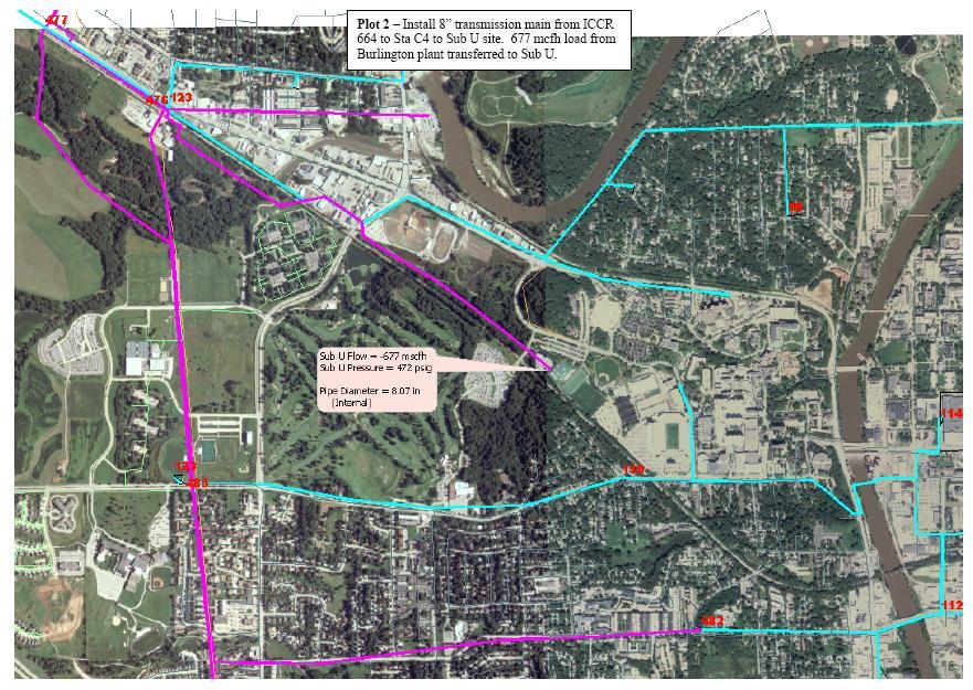
60 Section 16 Fuel Supply Natural Gas Pipeline Options MidAmerican Energy proposed three options for supplying gas to the WCPP. For all options, MidAmerican Energy will design and install the gas pipeline and associated regulating station and sell them to the University of Iowa. Gas compression, if required, has not been included with MidAmerican s proposal. Natural Gas Supply Option 1 will entail installing approximately 23 miles of dedicated 10 inch transmission pipeline from Ainsworth, Iowa. Refer to Figure 16-1 for conceptual routing. The pipeline will deliver 800 Mcfh of natural gas at 540 psig. This option requires approval from the Iowa Utilities Board, which is anticipated to take 18 to 36 months after receipt of application. The application is anticipated to take 60 to 90 days to prepare. The estimated capital cost for this option is $28,061,080, including 30% gross up costs. This option appears to be cost prohibitive. Natural Gas Supply Option 2 will entail installing approximately 9000 feet of 8 inch transmission pipeline from a tap near 10 th Avenue and 2 nd Street in Iowa City. Refer to Figure 16-2 for conceptual routing. The pipeline will typically operate between 300 and 350 psig and deliver up to 667 Mcfh. This option requires approval from the Iowa Utilities Board, which is anticipated to take 18 to 36 months after receipt of application. The application is anticipated to take 60 to 90 days to prepare. The estimated capital cost for this option is $3,760,900, including 30% gross up costs. Natural Gas Supply Option 3, also referred to as the Melrose pipeline, will entail installing approximately 2500 feet of 8 inch transmission pipeline from a tap near the Athletic Club which is located east of the entrance to Finkbine Commuter Lot. Refer to Figure 16-3 for conceptual routing. The pipeline will typically operate between 85 and 90 psig and deliver up to 400 Mcfh. This option does not require approval from the Iowa Utilities Board. The estimated capital cost for this option is $1,107,600, including 30% gross up costs. de:mkc:21212\admin_asst\aug-2009\section16.doc 16-1 Stanley Consultants

61 Natural Gas Supply Option 1 Figure 16-1 Natural Gas Supply Option 2 Figure 16-2 de:mkc:21212\admin_asst\aug-2009\section16.doc 16-2 Stanley Consultants
62 Natural Gas Supply Option 3 Figure 16-3 Solid Biomass Fuel The University of Iowa is currently investigating construction and demolition material, wood chips, Cedar River paper sludge, oat hulls, corn cobs, corn stover, corn kernels, and switchgrass as potential solid biomass fuel sources. Details, including availability and cost, are to be provided when completed. Solid fuel will likely be delivered to site by truck. Trucks will access the WCPP from Hawkins Drive via Finkbine Commuter Lot Drive. The service road around the south side of the plant will prevent truck traffic from disrupting commuter access or Cambus service. de:mkc:21212\admin_asst\aug-2009\section16.doc 16-3 Stanley Consultants
63 Section 17 Mechanical Distribution System Description A steam supply pipeline and condensate return pipeline will be installed underground between the West Campus Power Plant (WCPP) and the basement in the West Campus Chilled Water Plant (WCCWP). The pressure testable pre-engineered pipelines will be direct-buried with vaults with expansion joints for thermal growth. Slip-type expansion joints are included for the expansion joints. The steam and condensate pipes will be installed adjacent to each other in a common trench. Each pipeline will be approximately 3300 feet in length. The 12 inch carbon steel steam supply pipeline will be capable of transporting 200 kpph of 155 psig saturated steam for operating steam turbine driven chillers or for campus heating. The 6 inch stainless steel condensate return pipeline will transport campus condensate collected and pumped from a new condensate return pumping station located in the basement of the WCCWP. The condensate return system will be capable of transferring 400 gpm of 200F condensate. Routing The conceptual routing for the steam supply and condensate return pipelines is shown in Appendix A. The pipelines parallel each other and run along the east side of Finkbine Commuter Drive to Hawkins Drive; and along the south side of Hawkins Drive to the WCCWP. The pipelines cross the railroad tracks and several driveways. Space will be allocated adjacent to the pipelines for a future 12 inch steam pipeline and 6 inch condensate pipeline. Vaults will be sized for future build-out. de:mkc:21212\admin_asst\aug-2009\section17.doc 17-1 Stanley Consultants
64 Conceptual Cost Estimate Conceptual capital cost estimate for the mechanical distribution system were developed based on past similar projects and cost estimating references. Cost estimate details are included in Table B-39 in Appendix B. The estimated capital cost for the mechanical distribution system is $7,065,055. Other Considerations With regard to constructability, permits for boring and jacking will be necessary to cross the railroad tracks. Traffic impacts during construction along Hawkins Drive are expected to be minimal. de:mkc:21212\admin_asst\aug-2009\section17.doc 17-2 Stanley Consultants
65 Section 18 Sub U Upgrades Description The proposed location for electric tie-in from the West Campus Power Plant (WCPP) is Substation U. Substation U is connected to MidAmerican Energy s 161 kv transmission system. Based on preliminary evaluation, connecting the 33 MW combustion turbine will not require substation upgrades. There are, however, two potential concerns with installing 40-megawatts of new generation and interconnecting it into the existing Substation U. These limitations are the maximum current carrying capacity of the Substation U breakers and bus, and terminating all the cables on the existing breaker. The available 15kV circuit breaker in Substation U, intended for interconnection to the new generation station, has a continuous rating of 2000A. At 13.8kV, 2000A equates to approximately 47.8MVA of capacity. Ultimately, the limitations at the substation that would restrict the capacity of the new generation station, is the 2,000A rating. The new generation is limited to a combination of 2,000A of real and reactive power. Depending on the VAR support required from the generator to provide adequate voltage support to the campus, the generator may or may not be megawatt limited. As long as the combination of real and reactive amps do not exceed the 2,000A limit of Substation U modifications are not required. Other potential modifications that have not been evaluated are if adequate room exists on the 2,000A breaker cable terminations. Because the power is being transmitted underground through a duct bank system, the cables are larger in size and quantity then would typically be expected for a 2,000A breaker. This larger number and size of cables is due to the thermal limit of the cable insulation and special considerations must be taken to not overheat the cables when at their deepest point in the duct bank system. Breaker cable terminal pad upgrades are relatively easy and can be done at relatively low cost. de:mkc:21212\admin_asst\aug-2009\section18.doc 18-1 Stanley Consultants
66 Section kv Electrical Duct Bank Description The generation side at the West Campus Power Plant (WCPP) will produce electric power at 13.8kV on a low impedance grounded system. The existing underground campus electric distribution system operates at 13.8kV on a solidly grounded system. Because the systems are grounded differently, it is necessary to include an isolation transformer to segregate the generator grounding system from the distribution grounding system. The isolation transformer will be located at the WCPP with the generator breaker. Power on the distribution side of the transformer will be transmitted approximately 1000 feet to interconnect at Substation U. Two concrete duct banks will be installed underground between the WCPP and a new manhole behind the control buildings at Substation U. One duct bank will house supply cables from the WCPP, and the second duct bank will be available for a future plant of the same size. The duct banks will run parallel with a minimum spacing of 72 inches. Each duct bank will contain 24-6 inch conduits for electrical distribution cables and 4-2 inch conduits for communication cables. The distribution circuit will consist of kcmil conductors per phase and kcmil neutral conductors, with 1 conductor installed per conduit. Six spare 6 inch conduits will remain in each duct bank. Routing The conceptual 13.8kV electrical duct bank routing is shown in Appendix A. Two duct banks (one with cables and one sized for future plant expansion) will parallel each other and run along the east side of Finkbine Commuter Drive. The duct bank will turn and run parallel to the railroad tracks before crossing under and entering a new manhole behind the control buildings at Substation U. Several manhole pits will be located throughout the routing to accommodate cable installation. de:mkc:21212\admin_asst\aug-2009\section19.doc 19-1 Stanley Consultants
67 Conceptual Cost Estimate Conceptual capital cost estimate for the conceptual 13.8kV electrical duct banks were developed based on past similar projects and cost estimating references. Cost estimate details are included in Table B-40 in Appendix B. The estimated capital cost for the two 13.8kV electrical duct banks as described above, is $2,976,143. Other Considerations With regard to constructability, permits for boring and jacking will be necessary to cross the railroad tracks. de:mkc:21212\admin_asst\aug-2009\section19.doc 19-2 Stanley Consultants
68 Section 20 Water Supply and Discharge Description An underground potable water supply pipeline will be direct-buried between the West Campus Power Plant (WCPP) and tie-in on an existing campus water distribution pipe located near Substation U. The 6 inch ductile iron pipeline will supply water to the plant to be used for cycle make-up, service water, fire water, and potable water services. The pipeline will be approximately 800 feet in length. An underground discharge water pipeline will be direct-buried between the West Campus Power Plant (WCPP) and tie-in on an existing city sanitary sewer pipeline located near the Athletic Club on Melrose Avenue. An oil/water separator will be located at the WCPP to ensure plant discharge effluent is free of oil and grease prior to leaving the plant premises. The 6 inch ductile iron pipeline will transport plant discharge effluent into the City s sanitary sewer system. The pipeline will be approximately 2500 feet in length. Routing The conceptual routing for the potable water pipeline and plant discharge effluent pipeline is shown in Appendix A. The potable water supply pipeline will parallel the steam and condensate pipelines along the east side of Finkbine Commuter Drive before tying into an existing campus potable water distribution pipeline. The pipeline will cross the railroad tracks and a campus sidewalk. The plant discharge effluent pipeline is will parallel the driveway between Finkbine Commuter Lot and Melrose Avenue. de:mkc:21212\admin_asst\aug-2009\section20.doc 20-1 Stanley Consultants
69 Conceptual Cost Estimate Conceptual capital cost estimate for the water supply and discharge pipelines were developed based on past similar projects and cost estimating references. Cost estimate details are included in Table B-41 in Appendix B. The estimated capital cost for the water supply and discharge pipelines is $480,375. Other Considerations With regard to constructability, permits for boring and jacking will be necessary to cross the railroad tracks. de:mkc:21212\admin_asst\aug-2009\section20.doc 20-2 Stanley Consultants
70 Section 21 Emissions Non-PSD Permit Strategies It is estimated that a PSD review for air emissions could extend the project schedule by 2 years or more, depending on which pollutant(s) is being reviewed. The University of Iowa has expressed concern that the longer schedule could result in timing issues related to the WCPP s ability to serve as a backup power source for the Iowa Institute for Biomedical Discovery (IIBD) project currently scheduled to go operational in the fourth quarter of To avoid a PSD review, annual emissions from the WCPP must not exceed PSD thresholds. This can be accomplished either by limiting the number of hours of operation or by including additional emission control equipment. Annual emissions for the various options were projected to determine if PSD pollutant threshold limits would be exceeded for continuous full load operation. Emission rates used were based on vendor supplied information or emission factors from EPA s AP-42 tables. Where a pollutant exceeded the PSD threshold, an annual operating limit was calculated. As an alternate approach, emission control equipment was identified for reducing emissions below PSD thresholds. Emission control equipment capital costs were then estimated and are included in Sections 3 through 11 of this report. Results from the emission projection analysis are summarized in Appendix C. de:mkc:21212\admin_asst\aug-2009\section21.doc 21-1 Stanley Consultants
71 Appendix A Site Plan and Utilities Drawing de:mkc:21212\admin_asst\aug-2009\appa.doc A-1 Stanley Consultants
72
73 Appendix B Cost Estimate Spreadsheets de:mkc:21212\admin_asst\aug-2009\appb.doc B-1 Stanley Consultants
74 TABLE B-1 SUMMARY TABLE University of Iowa West Campus Power Plant Study August 27, 2009 Conceptual Capital Cost Estimate Estimated costs Options 1 Site Preparation $1,961,949 2 CT Option 1 $38,805,922 3 Building $3,983,868 4 Emission Control Equipment $4,939,658 5 CT Option 2 $32,984,364 6 Building $2,395,105 7 Emission Control Equipment $5,164,736 8 CT Option 3 $37,458,105 9 Building $2,395, Emission Control Equipment $5,606, CT Option 4 $46,175, Building $6,878, Emission Control Equipment $2,893, CT Option 5 $51,974, Building $5,319, Emission Control Equipment $6,631, Boiler Option 1 $5,281, Building $1,293, Emission Control Equipment $0 20 Boiler Option 2 $27,030, Building $8,572, Emission Control Equipment $7,684, Boiler Option 3 $33,232, Building $8,699, Emission Control Equipment $7,974, Boiler Option 4 $44,915, Building $6,296, Emission Control Equipment $7,556, Steam Turbine Option 1 $4,480, Building $297, Steam Turbine Option 2 $13,809, Building $572, Water Treatment Option 1 (155 psig) $459, Water Treatment Option 2 (900 psig) $2,980, Natural Gas Pipeline Option 1 $28,061, Natural Gas Pipeline Option 2 $3,760, Natural Gas Pipeline Option 3 $1,107, Mechanical Distribution $7,065, kV Electrical ductbank $2,976, Water Supply and Discharge Pipelines $480, Sub U Upgrades $0 NOTES: 1 Above is a summary of the results from the conceptual capital cost estimate ("estimate") tables that follow Costs associated with relocating displaced Finkbine Commuter Lot parking to existing Grant Field have not been accounted for in any of the estimates that follow. Costs associated with minimizing the building profile by locating major equipment in a basement have not been accounted for in any of the estimates that follow. Costs associated with a common stack for the site (single shell, multiple flue) and associated ductwork have not been accounted for in any of the estimates that follow. Costs for special structural provisions related to soil conditions at the proposed plant site have not been accounted for in any of the estimates that follow. Costs for disposal of hazardous materials encountered during excavation, if any, have not been accounted for in any of the estimates that follow. 7 Costs for site specific noise abatement requirements have not been accounted for in any of the estimates that follow. 8 For visual impact considerations, building cost was assumed to be $245 per square foot for all options. 1 of 19
75 University of Iowa West Campus Power Plant Study August 27, 2009 Conceptual Capital Cost Estimate TABLE B-2 SITE PREPARATION Description Unit Price (Equipment) Total Units Equipment Price Labor Price Total Installed Price 1 Major Equipment $ Balance-Of-Plant (BOP) Equipment $1,404,150 5 Finkbine parking lot demolition $695,750 1 $695,750 incl. $695,750 6 Grant field parking addition modifications $708,400 1 $708,400 incl. $708, Equipment Subtotal $1,404, Major Equipment Installation Contract: (10% of Major Equipment cost) $0 11 Undeveloped Design Details: (5% of Major Equipment cost + 15% of BOP Equipment cost) $210, Direct Cost Subtotal $1,614, Engineering, Permitting and Administrative / Commissioning: (8.5% of Direct Cost) $137, Contingency: (5% of Major Equipment cost + 10% of Direct Cost less Major Equipment cost) $161, Procure, Design, and Construct: (3% of Direct Cost) $48, Total Cost $1,961,949 *** Refer to "Notes" on page 1 for assumptions used in the development of the Table(s) above.*** 2 of 19
76 University of Iowa West Campus Power Plant Study August 27, 2009 Conceptual Capital Cost Estimate TABLE B-3 CT OPTION 1: BASELINE EQUIPMENT Description Unit Price (Equipment) Total Units Equipment Price Labor Price Total Installed Price 1 Major Equipment $19,706,250 2 Solar Mars 100 (10.7 MW at ISO) $5,650,000 2 $11,300,000 $2,260,000 $13,560,000 3 Inlet air chilling system $1,385,000 2 $2,770,000 $554,000 $3,324,000 4 Simple cycle stack and silencer $75,000 2 $150,000 $30,000 $180,000 5 HRSG (100 kpph, 170 psia) with diverter damper $1,815,000 1 $1,815,000 $635,250 $2,450,250 6 CEMS $160,000 1 $160,000 $32,000 $192, Balance-Of-Plant (BOP) Equipment $8,772,000 9 Black start gas-fired generator (500 kw) $420,000 1 $420,000 $84,000 $504, Gas compressor $390,000 3 $1,170,000 $234,000 $1,404, Gas conditioning equipment $30,000 2 $60,000 $12,000 $72, Condensate storage tank $65,000 1 $65,000 $13,000 $78, Condensate pump (200 gpm, SS, horizontal) $55,000 2 $110,000 $22,000 $132, Deaerator $65,000 1 $65,000 $13,000 $78, Boiler feedwater pump (200 gpm/155 psig) $165,000 3 $495,000 $99,000 $594, Steam line and boiler warming system $50,000 1 $50,000 $10,000 $60, Miscellaneous (compressed air, service water, fire protection) $320,000 1 $320,000 Incl. $320, Transformers $600,000 2 $1,200,000 $240,000 $1,440, Piping $1,570, Electrical $1,820, I & C $700, Equipment Subtotal $28,478, Major Equipment Installation Contract: (10% of Major Equipment cost) $1,970, Undeveloped Design Details: (5% of Major Equipment cost + 15% of BOP Equipment cost) $2,301, Direct Cost Subtotal $32,749, Engineering, Permitting and Administrative / Commissioning: (8.5% of Direct Cost) $2,783, Contingency: (5% of Major Equipment cost + 10% of Direct Cost less Major Equipment cost) $2,289, Procure, Design, and Construct: (3% of Direct Cost) $982, Total Cost $38,805,922 TABLE B-4 CT OPTION 1: BUILDING Total Unit Price Equipment Description (Materials) Total Units Price Labor Price Total Installed 40 Building - prefabricated metal 2,958,904 1 $2,958,904 Incl. $2,958, Mechanical 320,000 1 $320,000 Incl. $320, Direct Cost Subtotal $3,278, Engineering, Permitting and Administrative / Commissioning: (8.5% of Direct Cost) $278, Contingency: (10% of Direct Cost) $327, Procure, Design, and Construct: (3% of Direct Cost) $98, Total Cost $3,983,868 TABLE B-5 CT OPTION 1: EMISSION CONTROL EQUIPMENT Total Description Unit Price (Materials) Total Units Equipment Price Labor Price Total Installed 50 Major Equipment $3,687, SCR and CO catalyst for simple cycle 1,300,000 1 $1,300,000 $455,000 $1,755, SCR and CO catalyst for HRSG 710,000 1 $710,000 $142,000 $852, Urea conversion system 900,000 1 $900,000 $180,000 $1,080, Major Equipment Installation Contract: (10% of Major Equipment cost) $368, Undeveloped Design Details: (5% of Major Equipment cost) $184, Direct Cost Subtotal $4,240, Engineering, Permitting and Administrative / Commissioning: (8.5% of Direct Cost) $360, Contingency: (5% of Direct Cost) $212, Procure, Design, and Construct: (3% of Direct Cost) $127, Total Cost $4,939,658 *** Refer to "Notes" on page 1 for assumptions used in the development of the Table(s) above.*** 3 of 19
77 University of Iowa West Campus Power Plant Study August 27, 2009 Conceptual Capital Cost Estimate TABLE B-6 CT OPTION 2: BASELINE EQUIPMENT Description Unit Price (Equipment) Total Units Equipment Price Labor Price Total Installed Price 1 Major Equipment $18,672,000 2 GE LM2500 (22.8 MW at ISO) $13,230,000 1 $13,230,000 $2,646,000 $15,876,000 3 Inlet air chilling system $1,810,000 1 $1,810,000 $362,000 $2,172,000 4 Simple cycle stack and silencer $320,000 1 $320,000 $112,000 $432,000 5 CEMS $160,000 1 $160,000 $32,000 $192, Balance-Of-Plant (BOP) Equipment $5,602,800 8 Black start gas-fired generator (1000 kw) $475,000 1 $475,000 $95,000 $570,000 9 Gas compressor $500,000 2 $1,000,000 $200,000 $1,200, Gas conditioning equipment $44,000 1 $44,000 $8,800 $52, Miscellaneous (compressed air, service water, fire protection) $250,000 1 $250,000 Incl. $250, Transformers $1,050,000 1 $1,050,000 $210,000 $1,260, Piping $440, Electrical $1,400, I & C $430, Equipment Subtotal $24,274, Major Equipment Installation Contract: (10% of Major Equipment cost) $1,867, Undeveloped Design Details: (5% of Major Equipment cost + 15% of BOP Equipment cost) $1,774, Direct Cost Subtotal $27,916, Engineering, Permitting and Administrative / Commissioning: (8.5% of Direct Cost) $2,372, Contingency: (5% of Major Equipment cost + 10% of Direct Cost less Major Equipment cost) $1,858, Procure, Design, and Construct: (3% of Direct Cost) $837, Total Cost $32,984,364 TABLE B-7 CT OPTION 2: BUILDING Total Description Unit Price (Materials) Total Units Equipment Price Labor Price Total Installed 40 Building - prefabricated metal 1,781,280 1 $1,781,280 Incl. $1,781, Mechanical 190,000 1 $190,000 Incl. $190, Direct Cost Subtotal $1,971, Engineering, Permitting and Administrative / Commissioning: (8.5% of Direct Cost) $167, Contingency: (10% of Direct Cost) $197, Procure, Design, and Construct: (3% of Direct Cost) $59, Total Cost $2,395,105 TABLE B-8 CT OPTION 2: EMISSION CONTROL EQUIPMENT Total Description Unit Price (Materials) Total Units Equipment Price Labor Price Total Installed 50 Major Equipment $3,855, SCR and CO catalyst for simple cycle 2,100,000 1 $2,100,000 $735,000 $2,835, Urea conversion system 850,000 1 $850,000 $170,000 $1,020, Major Equipment Installation Contract: (10% of Major Equipment cost) $385, Undeveloped Design Details: (5% of Major Equipment cost) $192, Direct Cost Subtotal $4,433, Engineering, Permitting and Administrative / Commissioning: (8.5% of Direct Cost) $376, Contingency: (5% of Direct Cost) $221, Procure, Design, and Construct: (3% of Direct Cost) $132, Total Cost $5,164,736 *** Refer to "Notes" on page 1 for assumptions used in the development of the Table(s) above.*** 4 of 19
78 University of Iowa West Campus Power Plant Study August 27, 2009 Conceptual Capital Cost Estimate TABLE B-9 CT OPTION 3: BASELINE EQUIPMENT Description Unit Price (Equipment) Total Units Equipment Price Labor Price Total Installed Price 1 Major Equipment $21,359,178 2 GE LM2500+G4 (32.6 MW at ISO) $15,139,315 1 $15,139,315 $3,027,863 $18,167,178 3 Inlet air chilling system $2,140,000 1 $2,140,000 $428,000 $2,568,000 4 Simple cycle stack and silencer $360,000 1 $360,000 $72,000 $432,000 5 CEMS $160,000 1 $160,000 $32,000 $192, Balance-Of-Plant (BOP) Equipment $6,213,600 8 Black start gas-fired generator (1000 kw) $475,000 1 $475,000 $95,000 $570,000 9 Gas compressor $590,000 2 $1,180,000 $236,000 $1,416, Gas conditioning equipment $48,000 1 $48,000 $9,600 $57, Miscellaneous (compressed air, service water, fire protection) $230,000 1 $230,000 Incl. $230, Transformers $1,250,000 1 $1,250,000 $250,000 $1,500, Piping $440, Electrical $1,570, I & C $430, Equipment Subtotal $27,572, Major Equipment Installation Contract: (10% of Major Equipment cost) $2,135, Undeveloped Design Details: (5% of Major Equipment cost + 15% of BOP Equipment cost) $1,999, Direct Cost Subtotal $31,708, Engineering, Permitting and Administrative / Commissioning: (8.5% of Direct Cost) $2,695, Contingency: (5% of Major Equipment cost + 10% of Direct Cost less Major Equipment cost) $2,102, Procure, Design, and Construct: (3% of Direct Cost) $951, Total Cost $37,458,105 TABLE B-10 CT OPTION 3: BUILDING Total Description Unit Price (Materials) Total Units Equipment Price Labor Price Total Installed 40 Building - prefabricated metal 1,781,280 1 $1,781,280 Incl. $1,781, Mechanical 190,000 1 $190,000 Incl. $190, Direct Cost Subtotal $1,971, Engineering, Permitting and Administrative / Commissioning: (8.5% of Direct Cost) $167, Contingency: (10% of Direct Cost) $197, Procure, Design, and Construct: (3% of Direct Cost) $59, Total Cost $2,395,105 TABLE B-11 CT OPTION 3: EMISSION CONTROL EQUIPMENT Total Description Unit Price (Materials) Total Units Equipment Price Labor Price Total Installed 50 Major Equipment $4,185, SCR and CO catalyst for simple cycle 2,300,000 1 $2,300,000 $805,000 $3,105, Urea conversion system 900,000 1 $900,000 $180,000 $1,080, Major Equipment Installation Contract: (10% of Major Equipment cost) $418, Undeveloped Design Details: (5% of Major Equipment cost) $209, Direct Cost Subtotal $4,812, Engineering, Permitting and Administrative / Commissioning: (8.5% of Direct Cost) $409, Contingency: (5% of Direct Cost) $240, Procure, Design, and Construct: (3% of Direct Cost) $144, Total Cost $5,606,854 *** Refer to "Notes" on page 1 for assumptions used in the development of the Table(s) above.*** 5 of 19
79 University of Iowa West Campus Power Plant Study August 27, 2009 Conceptual Capital Cost Estimate TABLE B-12 CT OPTION 4: BASELINE EQUIPMENT Description Unit Price (Equipment) Total Units Equipment Price Labor Price Total Installed Price 1 Major Equipment $24,707,178 2 GE LM2500+G4 (32.6 MW at ISO) $15,139,315 1 $15,139,315 $3,027,863 $18,167,178 3 Inlet air chilling system $2,140,000 1 $2,140,000 $428,000 $2,568,000 4 HRSG (200 kpph, 170 psia) with duct firing $2,800,000 1 $2,800,000 $980,000 $3,780,000 5 CEMS $160,000 1 $160,000 $32,000 $192, Balance-Of-Plant (BOP) Equipment $9,224,600 8 Black start gas-fired generator (1000 kw) $475,000 1 $475,000 $95,000 $570,000 9 Gas compressor $590,000 2 $1,180,000 $236,000 $1,416, Gas conditioning equipment $48,000 1 $48,000 $9,600 $57, Condensate storage tank $65,000 1 $65,000 Incl. $65, Condensate pump (400 gpm, SS, horizontal) $85,000 2 $170,000 $34,000 $204, Deaerator $65,000 1 $65,000 $13,000 $78, Boiler feedwater pump (200 gpm/155 psig) $165,000 3 $495,000 $99,000 $594, Steam line and boiler warming system $50,000 1 $50,000 $10,000 $60, Miscellaneous (compressed air, service water, fire protection) $410,000 1 $410,000 Incl. $410, Transformers $1,250,000 1 $1,250,000 $250,000 $1,500, Piping $1,820, Electrical $1,570, I & C $880, Equipment Subtotal $33,931, Major Equipment Installation Contract: (10% of Major Equipment cost) $2,470, Undeveloped Design Details: (5% of Major Equipment cost + 15% of BOP Equipment cost) $2,619, Direct Cost Subtotal $39,021, Engineering, Permitting and Administrative / Commissioning: (8.5% of Direct Cost) $3,316, Contingency: (5% of Major Equipment cost + 10% of Direct Cost less Major Equipment cost) $2,666, Procure, Design, and Construct: (3% of Direct Cost) $1,170, Total Cost $46,175,818 TABLE B-13 CT OPTION 4: BUILDING Total Description Unit Price (Materials) Total Units Equipment Price Labor Price Total Installed 40 Building - prefabricated metal 5,121,180 1 $5,121,180 Incl. $5,121, Mechanical 540,000 1 $540,000 Incl. $540, Direct Cost Subtotal $5,661, Engineering, Permitting and Administrative / Commissioning: (8.5% of Direct Cost) $481, Contingency: (10% of Direct Cost) $566, Procure, Design, and Construct: (3% of Direct Cost) $169, Total Cost $6,878,334 TABLE B-14 CT OPTION 4: EMISSION CONTROL EQUIPMENT Total Description Unit Price (Materials) Total Units Equipment Price Labor Price Total Installed 50 Major Equipment $2,160, SCR and CO catalyst 800,000 1 $800,000 $280,000 $1,080, Urea conversion system 900,000 1 $900,000 $180,000 $1,080, Major Equipment Installation Contract: (10% of Major Equipment cost) $216, Undeveloped Design Details: (5% of Major Equipment cost) $108, Direct Cost Subtotal $2,484, Engineering, Permitting and Administrative / Commissioning: (8.5% of Direct Cost) $211, Contingency: (5% of Direct Cost) $124, Procure, Design, and Construct: (3% of Direct Cost) $74, Total Cost $2,893,860 *** Refer to "Notes" on page 1 for assumptions used in the development of the Table(s) above.*** 6 of 19
80 University of Iowa West Campus Power Plant Study August 27, 2009 Conceptual Capital Cost Estimate TABLE B-15 CT OPTION 5: BASELINE EQUIPMENT Description Unit Price (Equipment) Total Units Equipment Price Labor Price Total Installed Price 1 Major Equipment $30,672,000 2 GE Frame 6B (42.1 MW at ISO) $22,575,000 1 $22,575,000 $4,515,000 $27,090,000 3 Inlet air chilling system $2,400,000 1 $2,400,000 $480,000 $2,880,000 4 Simple cycle stack and silencer $405,000 1 $405,000 $81,000 $486,000 5 CEMS $180,000 1 $180,000 $36,000 $216, Balance-Of-Plant (BOP) Equipment $7,623,600 8 Black start gas-fired generator (1000 kw) $475,000 1 $475,000 $95,000 $570,000 9 Gas compressor $700,000 2 $1,400,000 $280,000 $1,680, Gas conditioning equipment $53,000 1 $53,000 $10,600 $63, Miscellaneous (compressed air, service water, fire protection) $280,000 1 $280,000 Incl. $280, Transformers $1,900,000 1 $1,900,000 $380,000 $2,280, Piping $530, Electrical $1,740, I & C $480, Equipment Subtotal $38,295, Major Equipment Installation Contract: (10% of Major Equipment cost) $3,067, Undeveloped Design Details: (5% of Major Equipment cost + 15% of BOP Equipment cost) $2,677, Direct Cost Subtotal $44,039, Engineering, Permitting and Administrative / Commissioning: (8.5% of Direct Cost) $3,743, Contingency: (5% of Major Equipment cost + 10% of Direct Cost less Major Equipment cost) $2,870, Procure, Design, and Construct: (3% of Direct Cost) $1,321, Total Cost $51,974,927 TABLE B-16 CT OPTION 5: BUILDING Total Description Unit Price (Materials) Total Units Equipment Price Labor Price Total Installed 40 Building - prefabricated metal 3,958,400 1 $3,958,400 Incl. $3,958, Mechanical 420,000 1 $420,000 Incl. $420, Direct Cost Subtotal $4,378, Engineering, Permitting and Administrative / Commissioning: (8.5% of Direct Cost) $372, Contingency: (10% of Direct Cost) $437, Procure, Design, and Construct: (3% of Direct Cost) $131, Total Cost $5,319,756 TABLE B-17 CT OPTION 5: EMISSION CONTROL EQUIPMENT Total Description Unit Price (Materials) Total Units Equipment Price Labor Price Total Installed 50 Major Equipment $4,950, SCR and CO catalyst for simple cycle 2,600,000 1 $2,600,000 $910,000 $3,510, Urea conversion system 1,200,000 1 $1,200,000 $240,000 $1,440, Major Equipment Installation Contract: (10% of Major Equipment cost) $495, Undeveloped Design Details: (5% of Major Equipment cost) $247, Direct Cost Subtotal $5,692, Engineering, Permitting and Administrative / Commissioning: (8.5% of Direct Cost) $483, Contingency: (5% of Direct Cost) $284, Procure, Design, and Construct: (3% of Direct Cost) $170, Total Cost $6,631,763 *** Refer to "Notes" on page 1 for assumptions used in the development of the Table(s) above.*** 7 of 19
81 University of Iowa West Campus Power Plant Study August 27, 2009 Conceptual Capital Cost Estimate TABLE B-18 BOILER OPTION 1: BASELINE EQUIPMENT Description Unit Price (Equipment) Total Units Equipment Price Labor Price Total Installed Price 1 Major Equipment $1,800,000 2 Package boiler (100kpph, 155 psig) and stack (3.5 ft dia, 50 ft, 9ppm ) $1,500,000 1 $1,500,000 $300,000 $1,800, Balance-Of-Plant (BOP) Equipment $2,044,000 8 Condensate storage tank (lined CS; 30,000 gal) $65,000 1 $65,000 $13,000 $78,000 9 Condensate pump (200 gpm, SS, horizontal) $55,000 2 $110,000 $22,000 $132, Deaerator $65,000 1 $65,000 $13,000 $78, Boiler feedwater pump (200 gpm/155 psig) $165,000 2 $330,000 $66,000 $396, Steam line and boiler warming system $50,000 1 $50,000 $10,000 $60, Miscellaneous (compressed air, service water, fire protection) $270,000 1 $270,000 Incl. $270, Piping $350, Electrical $360, I & C $320, Equipment Subtotal $3,844, Major Equipment Installation Contract: (10% of Major Equipment cost) $180, Undeveloped Design Details: (5% of Major Equipment cost + 15% of BOP Equipment cost) $396, Direct Cost Subtotal $4,420, Engineering, Permitting and Administrative / Commissioning: (8.5% of Direct Cost) $375, Contingency: (5% of Major Equipment cost + 10% of Direct Cost less Major Equipment cost) $352, Procure, Design, and Construct: (3% of Direct Cost) $132, Total Cost $5,281,029 TABLE B-19 BOILER OPTION 1: BUILDING Total Description Unit Price (Materials) Total Units Equipment Price Labor Price Total Installed 40 Building - prefabricated metal 964,860 1 $964,860 Incl. $964, Mechanical 100,000 1 $100,000 Incl. $100, Direct Cost Subtotal $1,064, Engineering, Permitting and Administrative / Commissioning: (8.5% of Direct Cost) $90, Contingency: (10% of Direct Cost) $106, Procure, Design, and Construct: (3% of Direct Cost) $31, Total Cost $1,293,805 TABLE B-20 BOILER OPTION 1: EMISSION CONTROL EQUIPMENT Total Description Unit Price (Materials) Total Units Equipment Price Labor Price Total Installed 50 Major Equipment $ Major Equipment Installation Contract: (10% of Major Equipment cost) $0 55 Undeveloped Design Details: (5% of Major Equipment cost) $0 56 Direct Cost Subtotal $ Engineering, Permitting and Administrative / Commissioning: (8.5% of Direct Cost) $0 59 Contingency: (5% of Direct Cost) $0 60 Procure, Design, and Construct: (3% of Direct Cost) $0 61 Total Cost $0 *** Refer to "Notes" on page 1 for assumptions used in the development of the Table(s) above.*** 8 of 19
82 University of Iowa West Campus Power Plant Study August 27, 2009 Conceptual Capital Cost Estimate TABLE B-21 BOILER OPTION 2: BASELINE EQUIPMENT Description Unit Price (Equipment) Total Units Equipment Price Labor Price Total Installed Price 1 Major Equipment $10,464,000 2 Biomass boiler with natural gas backup (60kpph, 155 psig) $4,200,000 2 $8,400,000 $1,680,000 $10,080,000 3 CEMS $160,000 2 $320,000 $64,000 $384, Balance-Of-Plant (BOP) Equipment $9,255,600 7 Condensate storage tank (lined CS; 30,000 gal) $65,000 1 $65,000 $13,000 $78,000 8 Condensate pump (120 gpm, SS, horizontal) $40,000 3 $120,000 $24,000 $144,000 9 Deaerator $65,000 1 $65,000 $13,000 $78, Boiler feedwater pump (120 gpm/155 psig) $121,000 3 $363,000 $72,600 $435, Steam line and boiler warming system $50,000 1 $50,000 $10,000 $60, Biomass / ash storage silos $1,500,000 1 $1,500,000 incl. $1,500, Loading and unloading building $1,000,000 1 $1,000,000 incl. $1,000, Biomass handling equipment $3,000,000 1 $3,000,000 $600,000 $3,600, Miscellaneous (compressed air, service water, fire protection) $340,000 1 $340,000 Incl. $340, Piping $1,220, Electrical $360, I & C $440, Equipment Subtotal $19,719, Major Equipment Installation Contract: (10% of Major Equipment cost) $1,046, Undeveloped Design Details: (5% of Major Equipment cost + 15% of BOP Equipment cost) $1,911, Direct Cost Subtotal $22,677, Engineering, Permitting and Administrative / Commissioning: (8.5% of Direct Cost) $1,927, Contingency: (5% of Major Equipment cost + 10% of Direct Cost less Major Equipment cost) $1,744, Procure, Design, and Construct: (3% of Direct Cost) $680, Total Cost $27,030,011 TABLE B-22 BOILER OPTION 2: BUILDING Total Description Unit Price (Materials) Total Units Equipment Price Labor Price Total Installed 40 Building - prefabricated metal 6,528,886 1 $6,528,886 Incl. $6,528, Mechanical 527,000 1 $527,000 Incl. $527, Direct Cost Subtotal $7,055, Engineering, Permitting and Administrative / Commissioning: (8.5% of Direct Cost) $599, Contingency: (10% of Direct Cost) $705, Procure, Design, and Construct: (3% of Direct Cost) $211, Total Cost $8,572,901 TABLE B-23 BOILER OPTION 2: EMISSION CONTROL EQUIPMENT Total Description Unit Price (Materials) Total Units Equipment Price Labor Price Total Installed 50 Major Equipment $5,736, Dry ESP $1,070,000 2 $2,140,000 $428,000 $2,568, Urea conversion system $800,000 2 $1,600,000 $320,000 $1,920, SCR and CO Catalyst $520,000 2 $1,040,000 $208,000 $1,248, Major Equipment Installation Contract: (10% of Major Equipment cost) $573, Undeveloped Design Details: (5% of Major Equipment cost) $286, Direct Cost Subtotal $6,596, Engineering, Permitting and Administrative / Commissioning: (8.5% of Direct Cost) $560, Contingency: (5% of Direct Cost) $329, Procure, Design, and Construct: (3% of Direct Cost) $197, Total Cost $7,684,806 *** Refer to "Notes" on page 1 for assumptions used in the development of the Table(s) above.*** 9 of 19
83 University of Iowa West Campus Power Plant Study August 27, 2009 Conceptual Capital Cost Estimate TABLE B-24 BOILER OPTION 3: BASELINE EQUIPMENT Description Unit Price (Equipment) Total Units Equipment Price Labor Price Total Installed Price 1 Major Equipment $14,064,000 2 Biomass boiler with natural gas backup (60kpph, 900 psig) $5,700,000 2 $11,400,000 $2,280,000 $13,680,000 3 CEMS $160,000 2 $320,000 $64,000 $384, Balance-Of-Plant (BOP) Equipment $10,223,200 7 Condensate storage tank (lined CS; 30,000 gal) $65,000 1 $65,000 $13,000 $78,000 8 Condensate pump (120 gpm, CS, vertical) $37,000 3 $111,000 $22,200 $133,200 9 Deaerator $65,000 1 $65,000 $13,000 $78, Boiler feedwater pump (120 gpm/900 psig) $190,000 3 $570,000 $114,000 $684, Condensate transfer pump (120 gpm, SS, horizontal) $40,000 3 $120,000 $24,000 $144, LP feedwater heater $55,000 1 $55,000 $11,000 $66, HP feedwater heater $75,000 1 $75,000 $15,000 $90, Steam line and boiler warming system $50,000 1 $50,000 $10,000 $60, Biomass / ash storage silos $1,500,000 1 $1,500,000 incl. $1,500, Loading and unloading building $1,000,000 1 $1,000,000 incl. $1,000, Biomass handling equipment $3,000,000 1 $3,000,000 $600,000 $3,600, Miscellaneous (compressed air, service water, fire protection) $340,000 1 $340,000 Incl. $340, Piping $1,650, Electrical $360, I & C $440, Equipment Subtotal $24,287, Major Equipment Installation Contract: (10% of Major Equipment cost) $1,406, Undeveloped Design Details: (5% of Major Equipment cost + 15% of BOP Equipment cost) $2,236, Direct Cost Subtotal $27,930, Engineering, Permitting and Administrative / Commissioning: (8.5% of Direct Cost) $2,374, Contingency: (5% of Major Equipment cost + 10% of Direct Cost less Major Equipment cost) $2,089, Procure, Design, and Construct: (3% of Direct Cost) $837, Total Cost $33,232,090 TABLE B-25 BOILER OPTION 3: BUILDING Total Description Unit Price (Materials) Total Units Equipment Price Labor Price Total Installed 40 Building - prefabricated metal 6,625,372 1 $6,625,372 Incl. $6,625, Mechanical 535,000 1 $535,000 Incl. $535, Direct Cost Subtotal $7,160, Engineering, Permitting and Administrative / Commissioning: (8.5% of Direct Cost) $608, Contingency: (10% of Direct Cost) $716, Procure, Design, and Construct: (3% of Direct Cost) $214, Total Cost $8,699,852 TABLE B-26 BOILER OPTION 3: EMISSION CONTROL EQUIPMENT Total Description Unit Price (Materials) Total Units Equipment Price Labor Price Total Installed 50 Major Equipment $5,952, Dry ESP $1,100,000 2 $2,200,000 $440,000 $2,640, Urea conversion system $850,000 2 $1,700,000 $340,000 $2,040, SCR and CO Catalyst $530,000 2 $1,060,000 $212,000 $1,272, Major Equipment Installation Contract: (10% of Major Equipment cost) $595, Undeveloped Design Details: (5% of Major Equipment cost) $297, Direct Cost Subtotal $6,844, Engineering, Permitting and Administrative / Commissioning: (8.5% of Direct Cost) $581, Contingency: (5% of Direct Cost) $342, Procure, Design, and Construct: (3% of Direct Cost) $205, Total Cost $7,974,192 *** Refer to "Notes" on page 1 for assumptions used in the development of the Table(s) above.*** 10 of 19
84 University of Iowa West Campus Power Plant Study August 27, 2009 Conceptual Capital Cost Estimate TABLE B-27 BOILER OPTION 4: BASELINE EQUIPMENT Description Unit Price (Equipment) Total Units Equipment Price Labor Price Total Installed Price 1 Major Equipment $22,872,000 2 CFB boiler w/ NG backup (120 kpph, 900 psig) $10,800,000 1 $10,800,000 $11,880,000 $22,680,000 3 CEMS $160,000 1 $160,000 $32,000 $192, Balance-Of-Plant (BOP) Equipment $10,092,400 7 Condensate storage tank (lined CS; 30,000 gal) $65,000 1 $65,000 $13,000 $78,000 8 Condensate pump (240 gpm, CS, vertical) $56,000 2 $112,000 $22,400 $134,400 9 Deaerator $65,000 1 $65,000 $13,000 $78, Boiler feedwater pump (240 gpm/900 psig) $230,000 2 $460,000 $92,000 $552, Condensate transfer pump (240 gpm, SS, horizontal) $60,000 2 $120,000 $24,000 $144, LP feedwater heater $55,000 1 $55,000 $11,000 $66, HP feedwater heater $75,000 1 $75,000 $15,000 $90, Steam line and boiler warming system $50,000 1 $50,000 $10,000 $60, Biomass / ash storage silos $1,500,000 1 $1,500,000 incl. $1,500, Loading and unloading building $1,000,000 1 $1,000,000 incl. $1,000, Biomass handling equipment $3,000,000 1 $3,000,000 $600,000 $3,600, Miscellaneous (compressed air, service water, fire protection) $340,000 1 $340,000 Incl. $340, Piping $1,650, Electrical $360, I & C $440, Equipment Subtotal $32,964, Major Equipment Installation Contract: (10% of Major Equipment cost) $2,287, Undeveloped Design Details: (5% of Major Equipment cost + 15% of BOP Equipment cost) $2,657, Direct Cost Subtotal $37,909, Engineering, Permitting and Administrative / Commissioning: (8.5% of Direct Cost) $3,222, Contingency: (5% of Major Equipment cost + 10% of Direct Cost less Major Equipment cost) $2,647, Procure, Design, and Construct: (3% of Direct Cost) $1,137, Total Cost $44,915,908 TABLE B-28 BOILER OPTION 4: BUILDING Total Description Unit Price (Materials) Total Units Equipment Price Labor Price Total Installed 40 Building - prefabricated metal 4,782,242 1 $4,782,242 Incl. $4,782, Mechanical 400,000 1 $400,000 Incl. $400, Direct Cost Subtotal $5,182, Engineering, Permitting and Administrative / Commissioning: (8.5% of Direct Cost) $440, Contingency: (10% of Direct Cost) $518, Procure, Design, and Construct: (3% of Direct Cost) $155, Total Cost $6,296,424 TABLE B-29 BOILER OPTION 4: EMISSION CONTROL EQUIPMENT Total Description Unit Price (Materials) Total Units Equipment Price Labor Price Total Installed 50 Major Equipment $5,640, Baghouse $2,700,000 1 $2,700,000 $540,000 $3,240, Urea conversion system $1,300,000 1 $1,300,000 $260,000 $1,560, SCR and CO Catalyst $700,000 1 $700,000 $140,000 $840, Major Equipment Installation Contract: (10% of Major Equipment cost) $564, Undeveloped Design Details: (5% of Major Equipment cost) $282, Direct Cost Subtotal $6,486, Engineering, Permitting and Administrative / Commissioning: (8.5% of Direct Cost) $551, Contingency: (5% of Direct Cost) $324, Procure, Design, and Construct: (3% of Direct Cost) $194, Total Cost $7,556,190 Notes: 1. Stack will be furnished with the emission control equipment. *** Refer to "Notes" on page 1 for assumptions used in the development of the Table(s) above.*** 11 of 19
85 University of Iowa West Campus Power Plant Study August 27, 2009 Conceptual Capital Cost Estimate TABLE B-30 ST OPTION 1: BASELINE EQUIPMENT Description Unit Price (Equipment) Total Units Equipment Price Labor Price Total Installed Price 1 Major Equipment $2,600,000 2 Backpressure turbine (4 MW) $2,000,000 1 $2,000,000 $600,000 $2,600, Balance-Of-Plant (BOP) Equipment $700,000 7 Turbine bypass letdown station $75,000 1 $75,000 $15,000 $90,000 8 Piping $310,000 9 Electrical $170, I & C $130, Equipment Subtotal $3,300, Major Equipment Installation Contract: (10% of Major Equipment cost) $260, Undeveloped Design Details: (5% of Major Equipment cost + 15% of BOP Equipment cost) $235, Direct Cost Subtotal $3,795, Engineering, Permitting and Administrative / Commissioning: (8.5% of Direct Cost) $322, Contingency: (5% of Major Equipment cost + 10% of Direct Cost less Major Equipment cost) $249, Procure, Design, and Construct: (3% of Direct Cost) $113, Total Cost $4,480,925 TABLE B-31 ST OPTION 1: BUILDING Total Description Unit Price (Materials) Total Units Equipment Price Labor Price Total Installed 40 Building - prefabricated metal 235,030 1 $235,030 Incl. $235, Mechanical 10,000 1 $10,000 Incl. $10, Direct Cost Subtotal $245, Engineering, Permitting and Administrative / Commissioning: (8.5% of Direct Cost) $20, Contingency: (10% of Direct Cost) $24, Procure, Design, and Construct: (3% of Direct Cost) $7, Total Cost $297,711 *** Refer to "Notes" on page 1 for assumptions used in the development of the Table(s) above.*** 12 of 19
86 University of Iowa West Campus Power Plant Study August 27, 2009 Conceptual Capital Cost Estimate TABLE B-32 ST OPTION 2: BASELINE EQUIPMENT Description Unit Price (Equipment) Total Units Equipment Price Labor Price Total Installed Price 1 Major Equipment $7,410,000 2 Condensing steam turbine (14 MW) $5,700,000 1 $5,700,000 $1,710,000 $7,410, Balance-Of-Plant (BOP) Equipment $2,738,800 8 Cooling tower $710,000 1 $710,000 $142,000 $852,000 9 Circulating water pump $182,000 2 $364,000 $72,800 $436, Circulating water chemical feed $150,000 1 $150,000 $30,000 $180, Condenser air extraction $50,000 1 $50,000 $10,000 $60, Transformers $500,000 1 $500,000 $100,000 $600, Piping $310, Electrical $170, I & C $130, Equipment Subtotal $10,148, Major Equipment Installation Contract: (10% of Major Equipment cost) $741, Undeveloped Design Details: (5% of Major Equipment cost + 15% of BOP Equipment cost) $781, Direct Cost Subtotal $11,671, Engineering, Permitting and Administrative / Commissioning: (8.5% of Direct Cost) $992, Contingency: (5% of Major Equipment cost + 10% of Direct Cost less Major Equipment cost) $796, Procure, Design, and Construct: (3% of Direct Cost) $350, Total Cost $13,809,911 TABLE B-33 ST OPTION 2: BUILDING Total Description Unit Price (Materials) Total Units Equipment Price Labor Price Total Installed 40 Building - prefabricated metal 451,258 1 $451,258 Incl. $451, Mechanical 20,000 1 $20,000 Incl. $20, Direct Cost Subtotal $471, Engineering, Permitting and Administrative / Commissioning: (8.5% of Direct Cost) $40, Contingency: (10% of Direct Cost) $47, Procure, Design, and Construct: (3% of Direct Cost) $14, Total Cost $572,578 *** Refer to "Notes" on page 1 for assumptions used in the development of the Table(s) above.*** 13 of 19
87 University of Iowa West Campus Power Plant Study August 27, 2009 Conceptual Capital Cost Estimate TABLE B-34 WT OPTION 1: 155 PSIG FEEDWATER Description Unit Price (Equipment) Total Units Equipment Price Labor Price Total Installed Price 1 Major Equipment $ Balance-Of-Plant (BOP) Equipment $329,000 5 Sodium regenerated condensate polisher $150,000 1 $150,000 $75,000 $225,000 6 Sodium zeolite softener (80% makeup water) $74,000 1 $74,000 $30,000 $104,000 7 Equipment Subtotal $329, Major Equipment Installation Contract: (10% of Major Equipment cost) $0 10 Undeveloped Design Details: (5% of Major Equipment cost + 15% of BOP Equipment cost) $49, Direct Cost Subtotal $378, Engineering, Permitting and Administrative / Commissioning: (8.5% of Direct Cost) $32, Contingency: (5% of Major Equipment cost + 10% of Direct Cost less Major Equipment cost) $37, Procure, Design, and Construct: (3% of Direct Cost) $11, Total Cost $459,695 *** Refer to "Notes" on page 1 for assumptions used in the development of the Table(s) above.*** 14 of 19
88 University of Iowa West Campus Power Plant Study August 27, 2009 Conceptual Capital Cost Estimate TABLE B-35 WT OPTION 2: 900 PSIG FEEDWATER Description Unit Price (Equipment) Total Units Equipment Price Labor Price Total Installed Price 1 Major Equipment $ Balance-Of-Plant (BOP) Equipment $2,133,200 5 Amine regenerated condensate polisher $505,000 1 $505,000 $101,000 $606,000 6 Sodium zeolite softener (80% makeup water) $74,000 1 $74,000 $30,000 $104,000 7 Two-pass RO with mixbed (80% makeup water) $1,186,000 1 $1,186,000 $237,200 $1,423,200 8 Equipment Subtotal $2,133, Major Equipment Installation Contract: (10% of Major Equipment cost) $0 11 Undeveloped Design Details: (5% of Major Equipment cost + 15% of BOP Equipment cost) $319, Direct Cost Subtotal $2,453, Engineering, Permitting and Administrative / Commissioning: (8.5% of Direct Cost) $208, Contingency: (5% of Major Equipment cost + 10% of Direct Cost less Major Equipment cost) $245, Procure, Design, and Construct: (3% of Direct Cost) $73, Total Cost $2,980,614 *** Refer to "Notes" on page 1 for assumptions used in the development of the Table(s) above.*** 15 of 19
89 University of Iowa West Campus Power Plant Study August 27, 2009 Conceptual Capital Cost Estimate TABLE B-36 NATURAL GAS OPTION 1: AINSWORTH PIPELINE (800 MCFH; APPROX 23 MILES) Unit Price Equipment Total Installed Description (Equipment) Total Units Price Labor Price Price 10 10" Transmission pipeline $21,586, plus 30% gross-up $6,475, Total Cost $28,061,800 TABLE B-37 NATURAL GAS OPTION 2: 10th AVENUE AND 2nd STREET PIPELINE (677 MCFH; APPROX 9000 FEET) Unit Price Equipment Total Installed Description (Equipment) Total Units Price Labor Price Price 20 8" Transmission pipeline $2,893, plus 30% gross-up $867, Total Cost $3,760,900 TABLE B-38 NATURAL GAS OPTION 3: MELROSE PIPELINE (400 MCFH, APPROX 2500 FEET) Unit Price Equipment Total Installed Description (Equipment) Total Units Price Labor Price Price 30 8" Transmission pipeline $852, plus 30% gross-up $255, Total Cost $1,107,600 *** Refer to "Notes" on page 1 for assumptions used in the development of the Table(s) above.*** 16 of 19
90 TABLE B-39 MECHANCAL DISTRIBUTION University of Iowa West Campus Power Plant Study August 27, 2009 Conceptual Capital Cost Estimate Description Unit Price (Equipment) Total Units Equipment Price Labor Price Total Installed Price 1 Major Equipment $ Balance-Of-Plant (BOP) Equipment $5,056,400 5 Condensate return unit (200 gpm) $47,000 1 $47,000 $9,400 $56, " steam (CS) and 6" condensate (SS) distribution (3300 ft, 5 vaults) $5,000,000 1 $5,000,000 incl. $5,000,000 7 Equipment Subtotal $5,056, Major Equipment Installation Contract: (10% of Major Equipment cost) $0 10 Undeveloped Design Details: (5% of Major Equipment cost + 15% of BOP Equipment cost) $758, Direct Cost Subtotal $5,814, Engineering, Permitting and Administrative / Commissioning: (8.5% of Direct Cost) $494, Contingency: (5% of Major Equipment cost + 10% of Direct Cost less Major Equipment cost) $581, Procure, Design, and Construct: (3% of Direct Cost) $174, Total Cost $7,065,055 *** Refer to "Notes" on page 1 for assumptions used in the development of the Table(s) above.*** 17 of 19
91 University of Iowa West Campus Power Plant Study August 27, 2009 Conceptual Capital Cost Estimate TABLE B kV ELECTRIC DUCTBANK Description Unit Price (Equipment) Total Units Equipment Price Labor Price Total Installed Price 1 Major Equipment $ Balance-Of-Plant (BOP) Equipment $2,130, kV Electric ductbank $2,130,000 1 $2,130,000 incl. $2,130,000 6 Equipment Subtotal $2,130, Major Equipment Installation Contract: (10% of Major Equipment cost) $0 9 Undeveloped Design Details: (5% of Major Equipment cost + 15% of BOP Equipment cost) $319, Direct Cost Subtotal $2,449, Engineering, Permitting and Administrative / Commissioning: (8.5% of Direct Cost) $208, Contingency: (5% of Major Equipment cost + 10% of Direct Cost less Major Equipment cost) $244, Procure, Design, and Construct: (3% of Direct Cost) $73, Total Cost $2,976,143 *** Refer to "Notes" on page 1 for assumptions used in the development of the Table(s) above.*** 18 of 19
92 University of Iowa West Campus Power Plant Study August 27, 2009 Conceptual Capital Cost Estimate TABLE B-41 WATER SUPPLY AND DISCHARGE Description Unit Price (Equipment) Total Units Equipment Price Labor Price Total Installed Price 1 Major Equipment $0 2 $0 3 4 Balance-Of-Plant (BOP) Equipment $343,800 5 Service water supply pipeline $113,800 1 $113,800 Incl. $113,800 6 Discharge water pipeline with O/W separator $230,000 1 $230,000 Incl. $230,000 7 Equipment Subtotal $343, Major Equipment Installation Contract: (10% of Major Equipment cost) $0 10 Undeveloped Design Details: (5% of Major Equipment cost + 15% of BOP Equipment cost) $51, Direct Cost Subtotal $395, Engineering, Permitting and Administrative / Commissioning: (8.5% of Direct Cost) $33, Contingency: (5% of Major Equipment cost + 10% of Direct Cost less Major Equipment cost) $39, Procure, Design, and Construct: (3% of Direct Cost) $11, Total Cost $480,375 *** Refer to "Notes" on page 1 for assumptions used in the development of the Table(s) above.*** 19 of 19
93 Appendix C Baseline Equipment Emission Projections de:mkc:21212\admin_asst\aug-2009\appc.doc C-1 Stanley Consultants
94 University of Iowa West Campus Power Plant Study August 27, 2009 Preliminary Baseline Equipment Emission Projections TABLE C-1: EMISSION RATE DATA: Boiler Emission Rates 3% O2) CT and HRSG Emission Rates 15% O 2) Boiler Option 1 Boiler Option 2 Boiler Option 3 Boiler Option 4 CT Option 1 CT Option 2 CT Option 3 CT Option 4 CT Option 5 type Pkg Blr (165 psig) Hurst (165 psig) Hurst (900 psig) BFB (900 psig) Mars 100 HRSG LM2500 LM2500+G4 LM2500+G4 w/hrsg HRSG Frame 6B output 100 kpph 2x60 kpph 2x60 kpph 120kpph 2x11MW 1x100 kpph 23MW 33MW 33MW 1x200 kpph 42MW fuel Natural gas Solid biomass Solid biomass Solid biomass Natural gas Natural gas Natural gas Natural gas Natural gas Natural gas Natural gas Notes: 2, 3, , 5, 6, 7 4, 5, 7 5, 7 5, 7 5, 7 4, 5, 7 5, 7 NOx, ppm: NOx, lb/mmbtu: NOx, lb/hr: CO, ppm: CO, lb/mmbtu: CO, lb/hr: PM, lb/mmbtu PM, lb/hr PM10, lb/mmbtu: PM10, lb/hr: VOC, lb/mmbtu: VOC, lb/hr: SO2, lb/mmbtu: SO2, lb/hr: TABLE C-2: PROJECTED ANNUAL EMISSIONS: boiler efficiency (HHV) steam production lb/hr steam pressure and temperature psig / F steam enthalpy (pressure, sat) btu/lb feedwater (200F) btu/lb heat input mmbtu/hr (HHV) Annual NOx emissions (8760 hrs full load operation) tpy Hours limit (limit to 39.4 tpy) hrs of operation Unlimited Annual CO emissions (8760 hrs full load operation) tpy Hours limit (limit to 99.4 tpy) hrs of operation Unlimited Unlimited Unlimited Unlimited 6768 Unlimited Annual PM emissions (8760 hrs full load operation) tpy Hours limit (limit to 24.4 tpy) hrs of operation Unlimited Unlimited Unlimited Unlimited Unlimited Unlimited Annual PM10 emissions (8760 hrs full load operation) tpy Hours limit (limit to 14.4 tpy) hrs of operation Unlimited Unlimited Unlimited Unlimited Unlimited Unlimited Annual VOC emissions (8760 hrs full load operation) tpy Hours limit (limit to 39.4 tpy) hrs of operation Unlimited Unlimited Unlimited Unlimited Unlimited Unlimited Unlimited Unlimited Unlimited Annual SO2 emissions (8760 hrs full load operation) tpy Hours limit (limit to 39.4 tpy) hrs of operation Unlimited Unlimited Unlimited Unlimited Unlimited Unlimited Unlimited Unlimited Unlimited Notes: 1. PSD threshold for NOx, SO2, and VOC is 40 TPY; CO is 100 TPY; PM is 25 TPY; PM10 is 15 TPY. 2. Nebraska Boiler indicated they could get down to 9 ppm with 25% excess air / 25% FGR system. 3. PPM values from Nebraska Boiler during phone conversation on 5/29/09. Use "Emission Calculator" to convert rates. 4. Option includes one (1) simple cycle CT and one (1) CT/HRSG with supplemental firing. 5. Combustion turbine heat consumptions based on heat rates and outputs of the machine at ISO conditions. 6. HRSG heat consumption based on Solar Mars 100 proposal. 7. Where not furnished by vendor, emission rates are based on emission factors from EPA's AP-42 tables. 1 of 1 8/27/2009
95 Appendix D OEM Quotes TOC Combustion Turbine Solar (10 MW CT)... 1 Combustion Turbine GE (23 MW CT)... 4 Combustion Turbine GE (33 MW CT) Combustion Turbine GE (40 MW CT) Package Boiler Nebraska Boiler (100 kpph) HRSG Rentech (For 15 MW CT) HRSG Rentech (For 33 MW CT) Solid Fuel Boiler Hurst (60 kpph, 250 psig & 850 psig) Solid Fuel Boiler Hurst (60 kpph, 750 psig) BFB B&W (120 kpph) Back Pressure Steam Turbine Dresser Rand (40 MW) Condensing Pressure Steam Turbine Dresser Rand (4 MW) Urea Conversion System Fuel Tech (For 35 MW CT) Simple Cycle SCR Braden (For 33 MW CT) SCR Peerless (For 33 MW CT) Inlet Air Chilling T.A.S. (For 33 MW CT) Gas Compressor Ariel Compressors (For 33 MW CT) Diesel Generator Altorfer (750 kw) Gas Pipeline Cost MidAmerican Engery de:mkc:21212\admin_asst\aug-2009\appd.doc D-1 Stanley Consultants
96 Solar Turbines Incorporated Budgetary Quotation for University of Iowa Inquiry # TBD prepared on July 23, 2008 For more information contact: Stefan Krajewski, , StefanK@Cogen-Energy.ca (Prices shown below quoted in US Dollars $) This quote is provided for budgetary purposes only and does not represent a firm quote. Gas Turbine Equipment (1) Gas Fuel MARS 100-T15000S Turbine Generator Set Commissioning Parts, Startup, and Site Testing $5,268,300 $150,000 Electrical Equipment Station Control System $169,500 Power and Utility Breaker Control Options Included in SCS Switchgear and MCC (design description below) $272,900 Switchgear, motor control center, auxiliary power transformer, and generator grounding resistor. Switchgear and MCC are shipped loose. Total for Electrical Equipment $442,400 Mechanical Equipment 1 Heat Recovery Steam Generator with ductburners $1,269,700 HRSG Options. none selected Diverter Valve.. $305,300 Diverter Valve Options $9,400 Deaerator.. $58,600 Feedwater Pumps and Valves. $491,200 Total for Heat Recovery Steam System Miscellaneous Construction Estimate. Project Management & Engineering. Shipping Development Costs Special or Avoided Capital Items 6% Balance of Plant Contingency Total for BOP Equipment and Installation. Grand Total for Turbomachinery and Balance of Plant. Estimation of cost per ISO rating kilowatt for selected equipment $2,134,200 $2,561,600 $662,100 $164,500 $0 $0 $357,900 $6,322,700 $11,741,000 $1,099 *Duties and taxes not included in estimate. Caterpillar Confidential: Green CEP Ver. 4.5 Page 1 of
97 MARS 100-T15000S Generator Set Package Features Engine: Two shaft turbine, designed for industrial use Axial compressor design Annual type combustor employing dry, low NOx technology Basic Options: Fully enclosed, generator set package requiring 460V, 3-phase, 60 Hz AC power Rated Class I, Div II, Groups C,D per NEC 120V, 1-phase, 50/60 Hz internal lighting and heater power Gas turbine engine in upward oriented air inlet, and upward oriented exhaust outlet 1800 rpm; 60 Hz Gearbox Continuous Duty, Open Drip Proof generator rated for 13,800 VAC with Class F insulation, B rise Included Package Features: Direct AC start motor system Simplex lube oil filter system Allen-Bradley based Turbotronics IV control system including: - Ethernet network interface - Touch Screen display with Engine Performance map - Software for heat recovery interface (without diverter valve control) - Software for CO2 system "lock out" (maintenance access to enclosure) - Backup Safety Shutdown System - kw Control - kvar/power Factor Control Included Factory Testing/Customer Witness/Quality Control Documentation: Standard package static testing Factory vibration testing Factory emissions testing per Solar's ES 9-97 Observation on "Non-Interference" basis Quality Control documentation Field-installed Ancillary Equipment (excludes ducting): Cross-flow type, self-cleaning engine air inlet filter (customer-supplied air), with bottom outlet Engine air inlet silencer Exhaust bellows (interface to waste heat recovery equipment) "Elbow" type enclosure inlet/exhaust ventilation system with silencer Included "Off-Skid" Components/Systems: Remote desktop PC/monitor and Printer/Logger Gas fuel flow meter (for Gas-only and Dual Fuel configurations) AC motor-driven Liquid Fuel boost pump skid (for Liquid Fuel configurations) 3-micron duplex filter/coalescer with auto drain (for Liquid Fuel configurations) CO2 system cabinet Air/Oil lube oil cooler VRLA Batteries with 120V DC charging system (back-up post lube) Portable engine cleaning cart Miscellaneous Short-term preservation for shipment Four (4) paper copies of Solar's Instruction, Operation and Maintenance manuals Four (4) CD-ROM copies of Solar's Instruction, Operation and Maintenance manuals UV Light and Gas Sensor test kit Internal equipment handling system Caterpillar Confidential: Green CEP Ver. 4.5 Page 2 of
98 Gas Turbine: KW Gross ISO Conditions: Site Ambient Temperature for Performance Analysis: Site Elevation for Performance Analysis: Site Ambient Relative Humidity for Performance Analysis: Turbine Inlet Pressure Loss: Turbine Outlet Pressure Loss: Turbine Fuel specified site conditions (LHV): KW Gross specified site conditions: Turbine Auxiliary Power Consumption: Total Auxiliary Power Consumption: Net Turbine Power Production: Black Start kw Requirement (Turbine Generator Set Only) Boiler: Condensate Return: Condensate Temperature: Makeup Water Temperature: Process Steam Pressure: Process Steam Temperature: Steam Contributed by Gas Turbine: Steam Contributed by Ductburners: Ductburner Fuel Consumption (LHV): Deaerator Steam Consumption: Boiler Steam Flow: Steam Flow to Process: Cogeneration Plant Estimated Performance Summary University of Iowa Solar Turbines Incorporated July 23, 2008 Performance listed below is estimated, not guaranteed. 10, , KW 27 KW 10,003 KW 232 KW ,930 57, , , ,000 KW F feet % "H2O "H2O MMBtu/hr KW % F F psig F lb/hr lb/hr MMBtu/hr lb/hr lb/hr lb/hr Cycle Performance (lower heating value basis): Net Turbine Heat Rate: 10,820 Btu/kWHR Gross Plant Heat Rate (Process steam or Tons converted to equivalent KW): 3,990 Btu/kWHR Overall Cycle Thermal Efficiency (LHV): 85.5 % Purpa Calculations (for reference only): Useful Thermal Output: 76.9 % Total Efficiency Standard: 52.0 % Caterpillar Confidential: Green CEP Ver. 4.5 Page 3 of
99 ! " # $! %&#&'!!( #$ %!!" & '' ( )*+ ",**-!. / 01 ( )*+-,-". 2 3**!* ' ( ()*. +"!,!!! 89)*. +"!,!! '#:#;'&#<;=8:#&;:=!"#!!$%!& '& "# ()&!%!! &!" )*+,,-.!"#$%&'
100 ,-./ / + * $ +,-.//+"""""""""""""""""""""""""""""""""""""""""""""""""""""""""""""""""""""""""""""""""""""""""""""""""""""""""""""""""""""""" 0" """"""""""""""""""""""""""""""""""""""""""""""""""""""""""""""""""""""""""""""""""""""""""""""""""""""""""""""""0 #3# -66**6-(-) # #3#3# +7-)* # #3#3 *)*( # #3#32 +7-)*)6+* # #3#38 +7-)**(* # #3#39 -)*("(* # #3#3 +7-)*:;+( #3#31 +*"(* #3#3& +7*-"(* #3#3$ *6("<+-6(("(* #3#3# -*(*6(-)"(* #3#3## -5-()("(* #3#3# ((*""(* #3#3#2 *)*((*6(-.* *" #3#3#8 =//-)*=>? ;"(* #3#3#9 )*)(*(-)5)<6>5**( #3#3# 0-)5%()<) #3#3#1 -)-) #3#3#&.* *)()<;)5* #3#3#$ */ )6**(-) #3 (-)@+- *)()<*.-6*;*6>-()<*6-(-) #33# 6("(-) #33 :(*)<*<6*@+- *)((-) #332 *.-6*(-) #338 6("(-)*6-(-) & #339 :(*)<*<6*@+- *)((-)*6-(-) #2 #33 :(*)<*<6*@+- *)()<*.-6*(-)*6-(-) # #32 - -(/)*5"6*A:6+-) #& ()*")+()(,)-./0 11#12 *(2%& *.34 5*
101 * $ + #323# - -(/)*5"6* #& #323 :6+-) #$ #38 *-5)-(* "..#, +""""""""""""""""""""""""""""""""""""""""""""""""""""""""""""""""""""""""""""""""""""""""""""""""""""""""0 3# -/-6-) # 3#3# B-<-(" # 3#3 :* # * # " *)(6;*<+* * -)(-)6;*<+* ;- *)(6;*<+* ()<<* A)<-(-) ",11/5#*"""""""""""""""""""""""""""""""""""""""""""""""""""""""""""""""""""""""""""""""""""""""""""""""""""""""""""""""""""""""""""6 23# +-<*6-/-6(-) #3# *++*!#' #3 -@+-<+*!' #32? (*!2' & 23#38? (*? ;!8' $ 23#39 -@+-<*(*5*)(!9' #3 +7*-!' # 23 "-60-)5-(A6;*<+* "-6*/ )6* <*A()<< (*;**( *+* *@+-* *)( & 231 ()<<* A)<-(-) $ ()*")+()(,)-./0 11#12 *(2%& *.34 5*
102 0" #3# -66**6-(-) "$"$" ) * $ + ;*9/ -"/5(+7-)**(0 ;/(5(+7-)*6)-(-)5/55*)*( )<-:(5*0*(+7-)*3;/(0*-() -((*<((;*<-.*)*@+- *)(((;* ;(*)<7" *)//*:-7*6+-)5*:(*)<-)5(;+5;(+))*0-(;-)(;**:;+( 6*6(3;*55*)*(6)-(/.-7*5* *("6 *%-)5*))+ 6 7+(%;-5;*+*(+7-)*%)66*"5*7:%)<6)()<66*-*3 ;*0*(+7-)*--:(5*0*(+7-)*%*<") -6"6+*<((;*5 5*)*()<<-.*)7"(;*55*)*(*:;+(53 ;*-)*(*6(-)%(/ (;*(+7-)* +)(*<-)*(7* +(;%-*@+-*<0-(; (-)*(** *;6**))<)")6>-)(;*-)*(-(* /=(6;)6*= (*6(-)5-)(/*-5)7C*6(< 5*((;*(+7-)*3;*(+7-)*-;6> +)(*< 0;*);-*<-)-(-)-)-<*(;*6>5*3;*6+-)5-*.*<)<;-*<-) *(*6)(-)*3 "$"$' + ;**)%-6*<%*5*)*(-67*/;)<-)5(;*/+6)(-)++0*/ (;*5(+7-)*()" 7-*)((* *(+*(;+5;+((;**(-)5)5*36-)5 0 (*)<-(6-(*</))<+ *)(*@+-*<3;*5*)*(-)6+<* 7+;**:6-((-)"(* 0-(;* )*)( 5)*(5*)*(3D*+()<-)*-<* 6+7-6**-)6+<*<3;*5*)*(- +)(*<)6+( *+-*<6)6*(*<3 "$"$# ), ;*()<<*@+- *)(-+-*<0-(;0*(;*/6+(-6*)6+*/(;*(+7-)*3 ;**)6+**<*-5)*<(6;-*.*)-*7(* *)(().*5*/$<!'(2/(3!#3 '0 ")<9/(3!#39 '7.*5<*<+-)5/+<*(-)3.--)/ (+7-)**..-/*-)6+<*<3;*(+7-)*6 ( *)(-/+".*)(-(*<0-(; /)3*<+)<)(/)-.-7*)(-)%)< 76>+-5;(-)56)7*.-<*<) (-)!** (-)'366*<)<*:-)/-5;(-)5*.-<*<3 "$"$/ )0. (**7*(*-.-<*</(;*5(+7-)*3;*7*(*-<*-5)*<(.-<* +-(7*(*)5(;)<-)((-).--)(-(*3+/6**6(*<* )*5" ()<<(*.*)(6-)3 "$"$1 - ;*5(+7-)*6>5*-+-*<0-(; <+% +(-(5*/-((-)"(* 6)-(-)5 /0*(;*(*6(-))<-)*(6**)%*/-(*!(-)')</-)7-*/-(*3- /(;*(+7-)*.*)(-(-)"(* -/-(**<((;* **.*(+7-)*6 7+(-)-3 -(**<---*)6*<7*/**)(*-)5(;*(+7-)**)+ 3;-<*-5)*+(-)6 6( ()*")+()(,)-./0 11#12 *(2%& *.34 5*#
103 * $ + )5* *)()<*- -)(*(;*)**</6+( *+-*<-)*(<+6(-)50;*)(;* ()<<<*-5)-+(--*<3 ;*5*)*(-+-*<0-(;/-((-)"(* 6)-(-)5/0*(;*(*6(-)%-)*( 6**))<7-*/-(*3 ;*+-*<(/ )<<<*(*.-6*(;*-)*(/-(**6>5*<*(*"/ ;- *)(3*6-6+( -*</-(*)5* *)(6)7*+-*<%)<(;*"*@+(*< ))-)<-.-<+7-3 "$"$2 )3* ;*()<<*@+- *)(-+-*<0-(;*6()5+% -5;( )<;-)(!/(>-)5 /0 <'*:;+(+(*(0-(;6))*6(-)/)5*(/6--((*-)-)* +)(-)5/) - *6"6**:;+((6>3+( */+)-;*<*:)-)C-)(%<+6(-)5+(%)< +)(-)5;<0 ***@+-*</;*(*6.*"-6(-)3/*@+-*<%(;**:;+( /)5*6)7*((*<(*/( )<6)/-5+(-))(-)3- *6"6* -6(-)%0*//*)*:;+(-*)6** 7")(-)3 "$"$ 4- ;*()<<*@+- *)(-+-*<0-(;)(+5/+*"(* +-)5)**6()-6" 6)(*</+* *(*-)5..*3***)<-:23/5*+**@+-* *)(3 /+* +( **(*)**6(-6*6-/-6(-) #!***6(-)23#3#'3-@+-</+*)< <+/+*"(* *.-7*/6("(-)3 "$"$( )- ;*()<<*@+- *)(-+-*<0-(;(0 *(*+7*-"(* %)*/(;*5 (+7-)*!")(;*(-6-')<)*/(;*5*)*(! -)*-'3;*--)5-(-)* (**%)<(;*+7*-"(*..*;.*(-)*(**(- 3;*6*%/-(*%)< (+7-)*+7*-**.-* +)(*<))+:--"*@+- *)( <+*6(*<)*:(( (;*5(+7-)*7*(*3;*5*)*(+7*-*@+- *)()<-**.-* +)(*< )*(;*5*)*(3;*+:--"*@+- *)( <+*.-<*- -/-*<--)56))*6(-) )<*<+6*6+( *E-)((-)(- *)<6(3 +*:;*,(+7*6*)</-)/) 6**.-7*(-)3+7-)*+7*- +( **(!***6(-) 23#3'3 "$"$%,56 7,- ;*()<<*@+- *)(-+-*<0-(;;"<+-6((-)5"(* %0;-6;-)6+<*) **6(-6% (<-.*)%;"<+-6+ * 7"%/-(*%6*)<6)(% +)(*<) (;*+:--"*@+- *)( <+*3;"<+-6 (- +)(*<)(;*5(+7-)* 66*"5*7:((+)55*)*(;/(3-*)</-((-)5)(;*7*(*%+ ;"<+-6(+7-)5(6))*6(7*(0**)(;*+:--"*@+- *)( <+*)<(;* -) 7*(**/+)-;*<3 ()*")+()(,)-./0 11#12 *(2%& *.34 5*
104 "$"$"! 4,- * $ + ;*()<<*@+- *)(-+-*<0-(;)-)(*</-*(*6(-)"(* 6 *(*0-(; ;"<67)*)-)5)<(;* <*(*6(%--)5)<)*-)(;*(+7-)* 6 ( *)(3;*/-*(*6(-)"(* -)6+<*6"-)<*6)(-)-)5 +)(*<) *(*>-<38B 7((*")<6;5*(0*(;*/-*(*6(-)"(* - -)6+<*<3 )<;+(<0)*))+)6-(*<((;*+7-)*)()*!'3) +)<((;*(+7-)*-/(;*5<*(*6(<*(*6(;-5;5*.*%-/(;*"(* - *-)5(***(;* 3? ;*)6(-.(*<%(;*6>5*;+(<0)%)<(;*- " 6"-)<*-<-6;5*<-)((;*(+7-)*6 ( *)(.- +(-*)*%)<(;*.*)(-(-)< *+( (-6"6*3/(*(- *<*")<-/*@+-*<%(;***.* +"/ -<-6;5*<3 "$"$"" 8 9- ;*()<<*@+- *)(-+-*<0-(;/**()<-)5+-(7*/ +)(-)5-)) -)<%));<+*3;*6)("(* /*(+*5 7*6)(*%.-7(-) )-(%/-*(*6(-)"(* %<-5-( *(*%)<<-5-(5*)*( (*6(-.**" <+*3))>-</+* )5* *)("(* )< *.-<*<(6 *(*(;*"(* 3;**(**6( <-"0-(;6).*)-*)((+6; 6**)6)(3 )<;+(<0)*.*)(*<-"*<)(;* +( (-6"3) (;*)*(, 8&9<7+(-.-<*<(() -(+)-(6)<-(-)!((+% *+*%(* *(+*%*(63'((;*6+( *E<-(-7+(*<6)("(* 30*/(;* 6)()*-.-<*<7"<*<-6(*<8B 7((*""(* 0-(;<+#F 66-(" 6;5*3 "$"$"' 0- ;**@+- *)(6>5*-+-*<0-(;8B 7((*""(* /(;*/-*(*6(-))< 5(+7-)*5*)*(6)("(* %<*6-7*<-)(;**6(-)37((*""(* *..**5+(*<*<6-<!B '("*3((*""(* ;-*/-)<6+( * -)((-)3/(;*(-)0*)(<+*-**6(*<% )*5"0--)((;* +-*<7((*""(* -)(;( <+*3 "$"$"# +, ;*()<<*@+- *)(-+-*<0-(; -66*7*<-)(*5(*<5*)*( (*6(-.*"(*!'% +)(*<-)(;*3;*(*6(-.**""(* -)6+<* /+)6(-))*6*"/(*6(-)/(;*5*)*(3 "$"$"/ :5:;< *- ;*()<<*@+- *)(-+-*<0-(;)=//-)*=6*)-)5"(* %0-(; 7-*0(* 0 ;6((;(6)7*+*</ +(-*+)-(3;* *"(* 6)7*+*</)-)* 6*)-)50*%0;-6;-//**<)(-)3+( *-*@+-*<(.-<*+-/-*< 0(* **(-)58!***6(-)23#38'%<*(*5*)( **(-)59!** *6(-)23#39'%)<-(#-5!$>5'/-(**<(132()<<3 ()*")+()(,)-./0 11#12 *(2%& *.34 5*
105 "$"$"1 -.97,;9 * $ +.*")*0 5(+7-)*-*/ )6*(*(*<+)<*<-) *(*%+-)56*<+* <*.**<//-5;((+7-)**-7--("3;*5*)*(-(*(*<(D 93#82832 ()<<(-(/6("/ )+/6(+*3 5(+7-)*5*)*(*(*6*-.*((-6(*(-)6+<-)5G 0-(6;((*!D 3 3D 33%6(+(-)%0--)5%)<*(-)(' * *(+*** *)(+(+(%)<0--)5 ) -((*)5*%+(+(%)<0--)5 *)-<*(-) )(..*(@+* (%*:6-((-)%)<*(+)-5) -*"(* 6)(-)+-("%)<<*.-6*6(+(-) "(* /+;-)5.*-/-6(-) +7-)5-)(*5-(" /+<(-)5(*(-.-7*)(-)3 "$"$" ;*6>5*-+-*<0-(;6+( *<0-)56>5*(;(-)6+<*5*)* )5* *)(<0-)5%/0 )<-)(+ *)(<-5 %**6(-6)*-)*<0-)5)< -)(*6))*6(-))<0-)53<<-(-)**6(-6<-5 )<5-6<0-)5*.-<*</*6<3**23/<*(-*<("-6-()<("-6<0-)5<*-.*"3 *(-)A -)(*))6*! A ')<)((-)A --)-)5!A ' )+*.-<*<)<*-)(*<-))5-;3-:;<6-*/(;* A )+%(;**;<6-* /(;*A )+%)<)* 0-(;7(;*-)6+<*<-)(;*7*//*-)53;* )+ 6.**(-)56)6*(/0*5*)*(-)5*@+- *)(%5+-<*((+7*;(-)5%7-6 -)/ (-))6 )*)(%)<*@+- *)(0-(;-)(;*(+7-)*5*)*(*(3 )*5".-<**)5-)**-)5<0-)5)*6+**.* C*6()*(36 36; 6+( *6)*)(*(;-<(7*)<.-*0%-)())((*C*6(<0-)53C*6(D*(.-<*(;*6+( *0-(;- *<-(*66*((;*(*(<0-)5*.--)3C*6(D*( **<C76 *(-))<.*0**>/(- * --)5<0-)576>)</(;3 "$"$" 9 ;*7*6*/+"-)6+<*;)<)(-)-)5/+(#*()<+*.-% 0;**(+<*)(*+ *<(;.*(*(C+)*" )E>)0 *<5*/**6(-6 5*)*(-)5)(*(-))<(7*/-6-*)(-)*<-)5--)5/0)<-)(+ *)( <0-)5% *6;)-6<0-)5%)<;.*0 >-)5>)0 *<5*/**6(-65*)*(%)< 5(+7-)*3;*6+*-<*-5)*<+)<)*-5;(;+<"%/-.*6)*6+(-.*<" 6;*<+*0-(;);++)6;7*>)</-/(**) -)+(*7*>*.*")*)<)*;/;+3 :*-*)6*<-)(+6(%+-)5*6-"<*.**<(-)-)5 (*-%.-<*/- ()*")+()(,)-./0 11#12 *(2%& *.34 5*
106 * $ + 5+)<0 >/7-6(;*"%+<.)6*<6)6*(0-(;6 )<;)<)(-)-)53 -)-)5-)6+<* +7-)* ---(-)+"(* *-5)A *(-))< -)(*))6*3 ;*(-)*6)<+6((;*6+*-)*6(+*,* -)/ (0;***6; C(-6- +(*<7"-(*(+*0-(;<*(-*<<*6-(-))<6-(*<*)5-)**-)5<0-)53 (+<*)((-)-)5 )+-5-.*)(*6;(+<*)()<(;*6-*)(H(+7-)*5*)*("(* -+*</;)<)(-)-)5(+* *)((;*6 -)(+6(-)3((;*6 *(-)/ *.**(*<(-6(;*(+<*)(*5-.*)5*-.**: -)(-)( *+*(;* *//*6(-.*)*/(;***)((-))<((-<*)(-/"-/)"(+<*)(;)(5*<(;* (*-3((;*6 *(-)/(;*6+*/-)*: -)(-)-5-.*)0;-6;6.*(;* *)(-*6+* (*-)<(+<*)(*5-.*)6*(-/-6(*/6 *(-)3 -)-)5-6)<+6(*<-) +()((;* )+/6(+-)5/6--("36(-)-)5((;* +( *H/6--("-.-7*+)*@+*(3;*+( *0 +<7**)-7*/.-<-)5)*6*"(-)-)5*@+- *)(!-6)<-(-)*<6 %B/ (.-<*"*%.*;*<C*6(%<"7<%6;>7<%*(63'/6*)(;*<((;* )+/6(+-)56(-)3 "$"$"( -.- 7*9 (-+)<*(<(;((;***;(;*-5;(( >*6;)5*-)<+6(<*-5))<<< -.* *)((<+6(*.-6*()"(- *0-(;+(-)6+-)5)"7-5(-)( -)((;* *)-)6))*6(-)0-(;(;*@+- *)(*.-6*.-<*<;**+)<*3 "$"$"% -,9 )*5"0-/+)-;))-(*(*(***)((-.*(7***)(<+-)5(;**:*6+(-)/ (;*5(+7-)**/ )6*(*(/0*+(+()<;*((*)"!)*(/ *@+- *)( )"-)- *6"6*-6(-)'3(;**/ )6*(*(*))*%* --)(*(-)5% )-*(*(-)5)<(;*(*(*(;**)-7--("/(;*6+( *7+( "7*//**< *(*"3 ()*")+()(,)-./0 11#12 *(2%& *.34 5*
107 #3 *)()<*.-6*;*6>-()<*6-(-)!')6+<*<!'I +(*<*(*" "$'$" 4,. * $ + (-) +7-)*!' (-) 9 +7-)* (-) 9J +7-)* (-) 9J 8 +7-)* (-) (")6*<? (*-*<*)*(!? ' (-) (")6*<--*<*)*(!' (-) (*)(*-<*:;+()<+:--">-< (-) (*)(*-<*-)*-<*)<D*+(+7-6* (-) -@+-<+*"(* (-)K ++*"(* (-)L? (*)C*6(-)"(*!' (-) "0 --)"(*! ' (-) +**)--(* (-)D 7+(-)--)5M.(-.*-)5 (-) 7+(-)--)5M;-*- (-) 7+(-)-*(-)5M+( **(*< (-)I +7*-*M-),) (-) +7*-*M +*:;*A +7* (-) 6>+-5;(-)5 (-) *<+)<)(B*)(-(-)"(*!' (-) D-6>*< -+ ((*-* (-)B )-)*? (*? ;"(* (-)? (-6 **(*6( (-) * (*? >((-) (-) +<(-)5*(!' (-)N? -)(*-(-)(M,& "$'$' 377,.=.-. (-) (-) (-) (-) (-) (-) (-) (-)!' (-) (-)KK!' (-)LL 6>(("(* 0*)(<+* )-(()(*)(* 0-(6;5* #9B ((*""(* )*(-;--)5"(* - *"6*:;+("(* *)*((*)/ * -(-/+7-6)( -@+-<+**)(-/+5*<+* )6;-)5"(* ()*")+()(,)-./0 11#12 *(2%& *.34 5*
108 (-)? (**( *)("(* "$'$#,. (-) *6;)-6+*.--) (-) )((-)*.-6* * $ + ()*")+()(,)-./0 11#12 *(2%& *.34 5*
109 "$'$/ 4,.8,., $ * $ + */ )6* # -) -)"(*<(0*+(+(/#13#? )<;*((*/$%19$ (+,>? ;3;-<+6(+(--* *-/-(*;+*)<5*)*((;)(;*9(.-<*(;*0*(O,? -7*35*-/-(*;+*%5*)*(%)<66*-*6) 7*.-<*<*(*(-)//+(+*5(+7-)*+5<*3 - $ */ )6* # -) -)"(*<(0*+(+(/3&? )<;*((*/$%82 (+,>? ;3;-<+6(+(--* *-/-(*;+*(;)(;*9J(.-<*(;* 0*(O,? -7*35*-/-(*;+*(;)(;*%5*)*(%)< 66*-*6)7*.-<*<*(*(-)//+(+*5(+7-)*+5<*3. $ */ )6* # -) -)"(*<(0*+(+(/$3$? )<;*((*/&%$81 (+,>? ;3;-<+6(+(--* *-/-(*;+*(;)(;*9J 8(.-<* (;*0*(O,? -7*35*-/-(*;+*%5*)*(%)<66*-*6)7*.-<*<*(*(-)//+(+*5(+7-)*+5<*3 5 6 $ */ )6* # -) -)"(*<(0*+(+(/23? )<;*((*/&%&1 (+,>? ;3!!!7 8,.! 97,.: 6+( *0;*/*6*<6-6+-(-"(* 0-(;0 (*,-6-)5-)6*/(;* /-(**<-6-)5"(* ) ".-<*<3+( * +(+"(*(*<0 (*%&9!$ '6*%((;*5*)*(3D*6*"/0 (*%*+*)<;*(*C*6(-) )+ 7**7*<)(;*5*)*(6;*)3/(;*6-)50 (*-(7**+*<% 6+( *+-*<6-6+(-)0 (*6-)5-*@+-*</(;**;*(*C*6(-)3 +*)("%)"+;5*)*(-.-7*0-(;(;-(-)3!!!, 8,.! 9,,.: 6+( *0;*/*6*<6-6+-(-"(* 0-(;-,-6-)5-)6*/(;* /-(**<-"(* ) ".-<*<3+*)("%)"+;5*)*(-.-7*0-(; (;-(-)3 # 6)<-(-)0-(;8P -)*()<P *:;+(%)D : 7(* *)(%#$%(+,7B)(+5%#23& >B)<3$0*/6(3 ()*")+()(,)-./0 11#12 *(2%& *.34 5*&
110 ,!+', '! +; * $ +.-*0*</ (;**:6-(**)</()<<+)-(%(;**:;+()<+:--">-<*6(*< )(;*-5;(-<*/(;*+)-(3? ;*)*6-/-*<%(;**6 )*)(6)7*0-(6;*<((;**/( -<*3,!+/!.$!.-*0*</ (;**:6-(**)</()<<+)-(%(;*5*)*(-)*-<*6+7-6*-)(;* */(;)<-<*)<(;*)*+(6+7-6*-)(;*-5;(;)<-<*3? ;*)*6-/-*<%(;* 6(-)/(;**6+7-6*6)7**.**<3 0*.*%(;*(* -)(-)7:/5*)*( -)(+ *)()<6)(0--)57:! '% +(* -))(;*-5;(;)<-<*3 # <!+ ;*5*+/+*"(* -<**(*<)<*6*<7"-@+-</+*"(* 3"-6-@+-</+* -)6+<*#% %K83+( * +(+"-@+-</+*((;*6))*6(-)((;*+:--" >-<(8-5!#2&1>5')<(*(!## '7.*(;*0 :-)( (* *(+*3+( *+-*</+* +(7*6*)%/-(**<)< **((;* *6-/-6(-)!***6(-)23#3'3;-(-)-)".-7*0-(;(;*-)5*))+ 6 7+(3+( * +(.-<*+"--)53 = 5!!+? ;*)*6-/-*<%(;*6>5*6)7*/+)-;*<0-(;6 *(*/+*"(* /(0<-//**)( /+*3;-6+<-)6+<*(0 5*+/+*%(0 -@+-</+*)*5*+)<)*-@+-< /+*3;)5*.*--)-(-(*< )+"((;*+)-(6)()*%+( (-6"%-/(;* *(-)5/+*+"*+*;+<5<+"<*6**3;-(-)-)".-7*0-(; (;*-)5*))+6 7+(3 > 7 #?+ -6(-)0-(;D : * --)- -((-)%0(*-)C*6(-) "7**@+-*<3;*0(* -)C*6(-)"(* 6)-(/-)*((-)*%+ %..*%--)5)<6)(/+*0-(; 5*+/+*%-@+-</+*<+/+*"(* 3? (*-)C*6(-)6)*<+6*D : * --)(9!9# 5,D 2 ')5*+/+*)<8!& 5,D 2 ')-@+-</+*3+( * +(.-<*+"/+-/-*<0 (** 0 (**6-/-6(-) 2!***6(-) 23#32'((;*0 (*-)C*6(-)>-<(9#9-5!28#2>5'3 5 & + 95 : <"0 * --)"(* 6)7*.-<*</+*)5*+/+*3;-"(* *<+6* * --).*(;**)(-*0*)5*0-(;+(0(*(* 3;* -)6 )*)(/ (;-"(* -)6+<** -:*<6 7+(%6 **/ *%6 *<-//+*% ;-5;*+*(+7-)*)*%6)("(* %/+*+""(* )<6; (5;3;- (-)-)(.-7*0-(;<+-@+-</+**(-)3 ()*")+()(,)-./0 11#12 *(2%& *.34 5*$
111 1!.!,! * $ + )*5"6)/+)-;+*6*)-/-(*/(;*5(+7-)*6>5*-)-*+/(;* ()<<7-*/-(*3;-(0 (5**/6*)-)5/-((-)"(* -+/<"%;-5; <+(*!<**(->*6)<-(-)'0*6<0*(;**).-) *)(;<+6; 70-)5)0%;/()<-6*/53-((-)** *)(*+*<(6*)(;*/-(*3;* +-)5-**(*<+)(-*<*(* -)*<.+*-*6;*<3;**@+-*<-6 *- (/(;*6+( *6*3 /. $,.!(@)).!( -6(-)0;*);-5;<"7+7(* *(+**6 )(0 *(-.*;+ -<-("% *.(-.*6-)56)7*+(--*<(-)6**0*+(+(3 ;-"(* -<*-5)*</*6-6+(-)/*.(-.*6-)50 (*/ + -)(;* 7(( /(;*-)*(-/-(*3+( * +(+"/-(**<%(7*0 (*(/)5*< 6))*6(-))(;*/-(*;+*)< +(<-*/0 (*0 (*/ (;*70 <0)..*3. $,.!(@.!!.! 0*-)5(;*6 7+(-)--)*((* *(+*6)-)6**(;*0*+(+(3? ;*) *6-/-*<% )*5"6)/+)-;;-5;*/ )6*-)*(-6;--)56-)-)(*5( /(;*--)*("(* 3+( *.-<*<*@+(*@+)(-(-*/6;-*<0 (*)< -)(*6))*6(-)5--)5()*5"/+)-;*<6;--)56-(/-(*;+*3 1. $, (@. )(-6*6-**6 *)<*<(0 /**(-)<+-)5-6-)5,0-)(*6)<-(-)3;* "(* *@+-*;(0 (*,5"6+(-)%(7*/+)-;*<7"(;*6+( *%(6-6+(* (;+5;(;*;*(*:6;)5*6--)(;*-)*(-"(* 3 A $!.!@B ;-*6*(;*()<<- *:;*)<(+7*6*/(;*+7*-"(* 3- *: 6*/-)/)6*0-(;<+/)- +)(*<)*(*/+)<(-)3 $!.!@5!'+!!C $ +( *0;*/*<+*:;*)<(+7*-6*6)**6((;* )(-)( *6*+()<<- *:;*)<(+7* ;(( )*5"6)/+)-;* *5*)6"-5;(-)5-)(;*(+7-)**)6+*)(-)3-5;((+))-/0*/-3 D!+ )*5"6)/+)-;*<+)<)(/))</-*< */(;*(+7-)*.*)(-(-)"(* 3 ()*")+()(,)-./0 11#12 *(2%& *.34 5*#
112 2 / ;!. - * $ + )*5"6)/+)-;)-6>*6< -+ 7((*-*)(-)(*6*+()<<*< ((*-*3 D ? ;*)*6-/-*<%(;*6>5*6)7*+-*<0-(;)Q)-)*P0 ;"(* %0;-6;0 6+( *(6*)(;*6 **6(-)/(;*(+7-)*<+-)5/+0**(-)3;* )*6*")*)<--)5*+-*<)<(;* *-)<0 (**@+-* *)(+(--*< 7"(;*()<<Q//-)*P"(* *)**<*<3 7!! 5 )*5"6).-<*/-*(*6(-)"(* (-6/ *<*(*6(/(;*(+7-)* *)6+*0;*)*@+-*<7"(;*6+( *3 * 7 ; )*5"6)/+)-; * (*? >((-)(/(;*6)("(* 3;* <+* 6)-(/G *>(*@+-*<0-(;)(;*)*(,*-(/6 +)-6(-)0-(; (;*)("(* )- (*<5;-6<-"/(;*(+7-)*%5*)*(%)<+:--""(* )5 )<<-5-( *(* -(-655-)5)<(*)<-)5"(* (;(6)(*,<-";-(-6<( )6+<*(;*67--("(.-<**-<-6*(.-<*(;*67--("(((%(%)<6)((;*5(+7-)*5*)*("(* /(* )+0-(6;)(;*+7-)*)()*-0-(6;*<(* (*6)(3 3!!+( )*5"6)6)<+6(/+**<%/+<(-)5(*(0-(;(;**:6*(-)/0 (*-)C*6(-) D : 7(* *)("(* 3 E *@+- *)(*(-)5-)6<6- (*%7*0 8R!838R'% *6 *)< 0-)(*-(-)(-)3;-(-) "-)6+<*%7+()(- -(*<((;*/0-)5 <-/-6(-)<**)<-)5)(;**.*/0-)(*-(-)*@+-*<G )*(-)(--6-)5!** (-) )< (-)' *((6-)5)<-)+(-)/-67*+)-( +)(*<--)5 )6-)5)<;*(-)5*:*<-)(+ *)()<*@+- *)(%**6(*<7" )*5"3? -)(*-(-)*)6+*/(;*+:--">-<)<(;*5*)*(%**6(*<7" )*5"3;**)6+*%0;*)*@+-*<%(*6(*@+- *)(-)6<0*(;*)<* *@+-*<0-(;;)<;*</-**:(-)5+-;*3 ()*")+()(,)-./0 11#12 *(2%& *.34 5*##
113 * $ + 7-*)((* *(+*7*0!M#13& '%(;*7.* <-/-6(-)+<<-(-) *6-*@+- *)(0-7**@+-*<3)+( )*5"/<*(-3 ()*")+()(,)-./0 11#12 *(2%& *.34 5*#
114 "$'$1 377,.=.-.8,.,, -!;++ * $ + 76>((%(;*<-**5*)*(.-<*0*/.*)(-(-)/)%66*-*)< ((* (35*<-**5*)*(*( "7**@+-*<-/)(+5/+* 6 *(;**6-+:---***(*<<+-)5(;*((-)5*@+*)6*3 -- 1&.!! )*5".-<*0 >-)%*/7-6(*<0*)(<+*!'<*-5)*</(;* -)((-)/(;*5(+7-)*6>5***6(-66)(5*-((;*-.((;* C7-(*3:- (*<- *)-)/(;**9/(:#9/(%29/(:#9/(%9/(:#9/(3 ;*6 *6 *(*0-(;)* *5*)6"-5;(-)5"(* %-)(*-67*("%-5;(-)5 )<6).*)-*)6**6*(6*3 ;**/7-6(*<6)(7+-<-)5;6)/ -)<*-5)%* 7"% (*-)< */ )6*0-(;(;**@+-* *)(/(;*(*(*<-(-)/(;*/0-)5()<<G D (-)*6(-6)+/6(+*6-(-) D (-)*6(-6<* D (-)-*(*6(-)6-(-) *-6))(-(+(*/(**)(+6(-) *-6)? *<-)56-*(" *-6)D (-)()<<)(-(+(* *-6)6-*("/*(-)5)<(*- )(-(+(*/*6(-6)<*6()-6)5-)** )-/ +-<-)5<* (**(+6(+*-)(-)5+)6-66+(-)/*(")<*(;< -)-((-) )*5"*6I 9? *<-)5)*6(-) )*5"M*)**6-/-6(-) )<-)()<<6-(-) -(;- *)(%(;*/0-)5*@+- *)(0-7**-)(*<)<0-*<-)((;*G +7-)*)()* +7-)*()(*)(* 8B)<#9B((*""(*.. 2.!. /**()<-)5-)*+/ (6)(/ (/+)-;*<7" )*5"6)7*+-*<3 ;*-+-(7*/-)<-)((-)-))(-) <+6)( (;*)) ;<+*-)66<)6*0-(; )*5")<+(-()(*6-/-6(-)3 ()*")+()(,)-./0 11#12 *(2%& *.34 5*#
115 5 5 +& ( * $ + )*5"6)+"(;*5*)*(6-6+-(7*>*)<*(*<0-(6;5*(/+ *@+- *)(6*3@+- *)(6)/ ((;* )*5")<+(-0-(6;5* *6-/-6(-)%(*6-/-6(-)/+)-;*<7"(;*6+( *)<*.-*0*<7" )*5" 7*/*@+((-)3 0D5.- + )*5".-<*6 )#9B 7((*""(* /(;*5(+7-)*6>5*3;* "(* -)6+<*7((*-*%6;5*)<#9B6-6+-(7*>*(;(*-)(*<-) /**()<-)5.*)(-(*<67-)*(/-)((-)-)(;*0*)(<+*!'3;* 7((*""(* *)6+*-)6+<*-6)(-) *)(("3 ;*<*-5)6;6(*-(-6/(;*#9B 7((*""(* */0 G ((*""* ((*"-*!;' #!,.!!(+ D-< # 6>5*<6;-* <+*%6)(-)-)5(;* C-("/(;**@+- *)()*6*"(6)<-(-) 6;-(;*-)*(-((;*5(+7-)*)< -)(-)(;*<*-*<0*+(+(<+-)5;(<" 6)<-(-)3)<<-(-)(*.(+ %6)<*)*+ %7)6*..*%6;*6>..*%;+(//..*%*:)-)()>%)<-)(*5--)5S(;*6>5*6)(-)(;*0 (* 6*<6*)(-/+56;-*.-<-)56;-*<0 (*((;*--)*(6-3 6 *(*-)< (6)(6*)(*)<6)()*6)(-)-)5(;***6(-6 0-(6;5*%7*>*)<0*<-(-7+(-)"(* -6(*<-)(;*6+(-6"(*(*<% *).-) *)("6)<-(-)*< <+*3;-6*)(*.-<*(;*-)(*/6*7*(0**)(;* -) 6)( )<(;*-)*(6;--)5"(* 3)<<-(-)(("-6(* *(+*-5)-)+(% (;*+)-(66*( )<;+(<0)<-*6(-))<+(+(6 *(**)(6 )-(-)57";<0-*<*-6))*6(-)3 ;**)6+*-(*/-*/6)(-)*<*)6+*0-(;((*5-6"6(*<!-)6+<-)5 *.7*/)*'66*)<*)("<3;*7-6>-<-.-<*<0-(;)6;7( ;*)<*.*-)57(//+)<(-) +)(-)5+*3;*6-)5(0*-)( -)6+<*<3 +!.!'+ )*5"6)/+)-;)*:;+(-*)6** 7"/- *6"6*-)((-)3;* * 7"-)6+<*)*:;+(*:)-)C-)(%$<*5***70%)<$<!'-*)6*0-(; -)(*)"-)+(*<8$(-)*(**-)-)5)<)*:;+((6>0-(;((;*-5;(/2/(!$3# '3 (-)-)6+<*<-//**)((6>;*-5;(%)&9<!'-*)6*% -)5()< (/ %)<<-.*(*..*//+(+* <+6(-)53 ()*")+()(,)-./0 11#12 *(2%& *.34 5*#
116 +82 * $ + )*5".-<*7+(%;-5;*//-6-*)6"(*+()/ *%<*-5)*<)<(*(*<( ()<<3)/ *;-5;.(5**.*%(6;)5*)</*("/*(+**7+-( ( (6;6+( *H-(**@+-* *)(3 ##!!$ )*5"/+)-;/-(/-/+7-6)()(-)3+7-6)((-)6+<*(+7-)*+7*-% 5*)*(+7*-)<;"<+-6((/+-<3 == <!.(! -@+-</+*6*)(-/+5*>-<-.-<*<(*.*0 (*7*<6)( -))(-)(;* 6+( *+-*</+*3;*"(* 6*)(;*/+*/ (;*6+( *+-*<(5* ()>)</0 <-(((;*6+( *+-*<<"()>3 >>, (+ )*5".-<*"(* +(---)5/-:(()6;(;*5(+7-)*5*)*(6>5* ((;*6+( */+)<(-)3;*"(* 0 /*-)((-))<-5) *)(/(;* +-*<*@+- *)(3 7 + )*5"6)+"0(*(*( *)("(* 6)/-5+*<(.-<*(;**@+-*<@+)(-(" )<@+-("/0 (*3;*<*-5)-)6(*/*(+*(*);)6**/ )6*%*-7--("% )<-)6(*<.)6*<**6(<*-)-(-)(*6;)5"(<*-.*;-5;+-("0 (* 0-(;+((;*)**</;<+6;* -63(-.-<*<6 *(*"* 7*<%-)(*< )<0-*<-)*(*()<)**)6+*3-*<* 7"-.-(+"*- -)(*<)< 6))*6(-)*@+-* *)(((;*C7-(** -)- %(;(/-*<76(*0 3-5; +-("0(*-*@+-*<-)(;*(+7-)**(-)*(*( *)(((- -**//-6-*)6"% *6-/-6"-)(;**)D : +*-)3 ()*")+()(,)-./0 11#12 *(2%& *.34 5*#
117 "$'$2 377,.=.- 7,.8,.,,,!+) * $ + )*5"0-.-<*(*6;)-6<.-"+*.--)*.-6*/(;*)((-))< --)-)5/(;*6 7+(-)(+7-)*6>5*3)((-)*.-6*0--)6+<* +*.--)5(;*-)((-)/(;*6 7+(-)(+7-)*6>5*7"(;* 0)*H6)(+6(-) 6)(6(3 --)-)5*.-6*0--)6+<*/+;-)5+*.--)%6;*6>+(%)< 6 --)-)5+*.--)/6 7+(-)(+7-)* *6;)-6"(* %6;*6>+()< 6 --)-)5+*.--)/6 7+(-)(+7-)***6(-6"(* %)<6;*6>+()< 6 --)-)5/(;*6 7+(-)(+7-)*6>5*6)("(* 3 )*5"0-.-<* 5*)*;)<(*@+-*</(;*6 --)-)5/(;*+)-(3+;-)5)<6-7(-) >-(6)7*.-<*<( )*5"()<<+7-;*<(*3 ;**))**@+-*<(-(*/(;*-)((-))<6 --)-)5/(;*6 7+(-) (+7-)*6>5*-)(*<7*0 3;*6*/0 >-)6+<*<-)(;-+ * (;((;*-)((-))<6 --)-)56;*<+*/(;*6 7+(-)(+7-)*6>5*-)( - 6(*<7"(;*-)((-))<6 --)-)56;*<+*/<<-(-)7)6*/)( *@+- *)((;(-)(.-<*<7" )*5"!+6;<* -)*-*<0 (*)(%(* (+7-)*%56 *%*(63'3 )*5"-(*)5*M)*!#'-)<-.-<+/((/ );+3 *6;)-6)<)(M(/ );+7*(0**)(;**-)<-.-<+ -)6+<*<-)(;**.-6*@+(*<*(;* (-)(+7-)*6>5*.*)< 0-7**@+-*<(6 --)*6-/-66 7+(-)(+7-)*6>5*6 )*)(3;** *)(*<7*0 G *)*(*6--(M;--)<-.-<+0-7**)-7*/(*(-)5/(;*5*)*()< 6 --)-)5/(;*+( (-6.(5**5+("(* 3 ;*) 0 >0**>0-7*- -(*<(;+!(*)!#';+*<"/-:!'<"* 0**>'3()<7"(- *0-7*7-*<-)6* *)(((;*;+)(*<7.*((;**//*6(-.* (*((- */*.-6*3/(;*)((-))< --)-)56;*<+*<-6((*)5* 0 >-)5;+<+(-)(;*)<<-(-)*+6*6)7*.-<*<))-)6* *)(<-" (*7-3;*-6-)5/(;***.-6*-)6+<*(.*)<-.-)5*:*)*)<-7*< )-)5* 7--(-)/*6;-)<-.-<+3+(-* 7--(-)*+(/(;* 0)*H6)(+6(-)6;*<+*0-7*7-*<66<-)5"3 )*5";.-<*<)*(- (*%)+ + 7-%/(;*/-*<*.-6**@+-* *)( **<+(-)(;-*6(-)/(;*3)<*(.-<*+ + )+ 7* )*5";+ *<6)(+6(-)6;*<+*(-.*((;* );+*(- (*-+((*< 7.*)<(;*(*;**(((- */(;*!***6(-)239'30*.*%(;**.-6* 0-7*7-*<((;*(*((- */*.-6*3;+<(;* 0)*H6;*<+*(;* 0)*H ()*")+()(,)-./0 11#12 *(2%& *.34 5*#
118 * $ + 6)(+6(-)6)(6(H*:*-*)6**+(-))-)6**-)(;*6)(+6(-)<+(-) + *<(;*(*(.*-)/(;**)6*<*.-6* (*0 +<7*-*<-(* ) )*5"0-6<-)(*)<.-<*()((-)*.-6*/5(+7-)*5*)*( *@+- *)(((;*6+( *C7-(*3!D G)((-)/**6(*<)6*/)( *@+- *)(6)7*.-<*<+)*@+*(3'//<-)5(C7-(*-7"(;*3 )*5"0-*.+(*%7*<)(;*C*6(-(*6)<-(-)%(;* (*:*<-(-+ *)/ ()(-)5(;**@+- *)((*)+*(- *")<6 -)(-.3 * /<*-.*"/(;* )*5"+-*<*@+- *)(0-7*()<)+)6*-<( 0)*HC7-(*!*)6(* '3/6*);- *)(-*@+-*<% )*5"; +(--*D D /55*<.**3 )*5";-)6+<*<)-)<-6(-.*()((-)6( /(;-//*(-6(") 7-((;-(- *36(+()((-)6(;7* 7-*<((;*+( *))6(+6(J#F 7-3 ()*")+()(,)-./0 11#12 *(2%& *.34 5*#
119 #32 - -(/ )*5"6*A :6+-) "$#$" - + 9,. * $ + -(*<7*0 *(;*- -(,*:6+-)((;* )*5"()<<6*/+"3--)5% 0--)5%67*%<+6(%*(636))*6(-)5((;**-)(-/+)-;*<7"6+( *!(;*' +)* <-/-*<7"*6-/-6(-)5** *)(3 < + --)5%-)6+<-)5+* %+*-% (* %-)5? (*%*(-)5? (*% * -)*-*<? (*%+7*-% **<-%)(+ *)(-% "<+-6((- )*(-(-(* +7-)*6>5*B*)(-(-),-) )*:;+( ( + )5*<(;*<*<6))*6(-)) )*5" 7*(*3 ( ;**!))()<<<+6(7"(;*' ( ;**!))()<<<+6(7"(;*' :;+(/)5*) -)7*(* )(+ *)() )*5"H*(* * -)7:)7*(* )(+ *)(0--)5-)+7-)*)( )* -5;B(5*))*6(-) *)*( +)<))*6(-) *6(-6( <<*)<(/ /--(* 8B((*-*)<;5*/ )("(* )<-*)< "(* * -)-)+7-)*)()* +7-) )*5"-)*-<*6+7-6* )*5"D*+(6+7-6* * -)7:)-)<-.-<+ ( <<*)<(/ /)*(--(* -)(*))6*)" ((*"(* -)(7*(*!-/+-*< *' ()*")+()(,)-./0 11#12 *(2%& *.34 5*#&
120 "$#$' 3, * $ + -.-*)5-)**-)5<*-5)/)">-)< +-<-)5)<6-.-0 > -(*/6--(-* +((**0 >)<;)5*/(;*5(+7-)*<+6(-)5%-*)6-)5%)<-* 0> -)*(%*:;+(%)<.*)(-(-)<+6(-)5(;*(;)-)6+<*<-)(;*6*/ +" -))<,.*)(--)5/ (;*5(+7-)*6>5*(* (*-)( +*(5*%(*( *)()</0 <-)5"(* -(*5+)<-)5-5;()-)5(*6(-) 0*"(* (+<-* *)-)5)< *(*-)5.(5*()/ * 6;-)*0*()/ *%)<6-(*<(*6(-) -</-+*<*(*6(-)*@+- *)( //<-)5%()((-))<(5* //>-<67-)5%)<<*-5)///>-<67*+(-)5 )6*/)()<*)*5"(- -(-)6)( )6;7(%* 7*< *)(%)<5+(-)5!@+(*<*(*"' -(-7+(*<)(6)( +( *E* (*6)( -*<+*.--)!@+(*<*(*"' -5;.(5*()/ *!'%67*%)<6-(*<*@+- *)( )(*6))*6(-)5--)5%6)<+-(%)<0--)57*(0**)*@+- *)( <+* )(+(--(-*%-)6+<-)56 **<-+")<//>-<--)5 ((*"6)(-) *)( +7*- *+* *)((;*(;)(;(<*/-)*<-)(;*6*/+" <<-(-)+7*-7*(;*<+6(-)5(;*(;)(;(<*/-)*<-)(;*6*/ +" +*()/*+ //>-</+*76>)<.*)(..* +*+"-*0 >7*")<(;*6*/+" *)*(6)((;*(;)(;(<*/-)*<-)(;*6*/+" <;-)56)( )6*/)(6)( -*<*/ )6**(-)5 -(*7 <<*%(-%)<(/ /*@+- *)(7*")<(;*5(+7-)* ()*")+()(,)-./0 11#12 *(2%& *.34 5*#$
121 #38 *-5)-(*- * $ + ;*/0-)5(7*+(-)*(;*6-(*-6)<-(-)((;**<C7-(*/(;*<*-5)/ (;**@+- *)(G 6(-) *.(-) -)- + -(** *(+* :- + -(** *(+* *-5)-)( 7-*)(* *(+*, *(-.* + -<-(" - "+*+6* *6)<"+*+6* *- *)(' *- -6*-5)-(*-! 6>5*' :- +? -)<**<!? -)<<' %-(*%*-5)(*5" %(*5"6--("0-(;#39 ()6*6( #8!-))-(' #9!--(*' /-.*,)0 < D*-*<D -*(2/(;-)()<9/(.*(-6%D# -*<D -*%D # $<!' <!'(8/(, (1/( D #G/-*<)-*-7*<)-)5*+)-()"*(-)3+(-*+)-(*(-)5( (;* *(- *0-;.*)- 6()7(;)*)<//-*<)-**.*3 ()*")+()(,)-./0 11#12 *(2%& *.34 5*
122 "..#, + 3# -/-6-)5 '$"$" >7 * $ + ;--.-<+)(-*(* 7*2%&3 '$"$' 3 D *+*(:*;.*7**)-)6+<*<-)(;-@+((-)3;*-6*@+(*<*:6+<*)" *<*%((*6(:*%/**%0;-6; "7*6-(*<0-(;(;*+6;**@+- *)( )<,*.-6*3 3-6* )* 9J)(+5)" +7-)**)*(*(-)6+<-)5(-)*@+- *)( *6-/-*<-)6+<*<!'-)*6(-)#3<*6-7*<-)(;*6*/+"3-6-)5-7*<)*:0 >/6("<*-.*"+)*(;*0-*((*<3 2/# *)*(*(-6*!*6;' O #%2%,.31#/ + (-) +7-)* O (-) 9 +7-)* O )6+<*< (-) 9J +7-)* O (-) 9J 8 +7-)* O (-) (")6*<? (*-*<*)*(!? ' O (-) (")6*<--*<*)*(!' O (-) (*)(*-<*:;+()<+:--">-< O (-) (*)(*-<*-)*-<*)<D*+(+7-6* O (-) -@+-<+*"(* O (-)K ++*"(* O (-)L? (*)C*6(-)"(* O (-) "0 --)"(*! ' O )6+<*< (-) +**)--(* O (-)D 7+(-)--)5M.(-.*-)5 O (-) 7+(-)--)5M;-*- O (-) 7+(-)-*(-)5M+( **(*< O (-)I +7*-*M-),) O (-) +7*-*M +*:;*A +7* O (-) 6>+-5;(-)5 O (-) *<+)<)(B*)(-(-)"(* O (-) D-6>*< -+ ((*-* O )6+<*< (-)B )-)*? (*? ;"(* O ()*")+()(,)-./0 11#12 *(2%& *.34 5*#
123 * $ + (-)? (-6 **(*6( O (-) * (*? >((-) O (-) +<(-)5*( O (-)N? -)(*-(-)(M,& O )6+<*< */55+.1A2#1 /1#/+ (-) 6>(("(* O (-) 0*)(<+* O (-) )-(()(*)(* O (-) 0-(6;5* O (-) #9B ((*""(* O (-) )*(-;--)5"(* O (-) - *"6*:;+("(* O (-) *)*((* )/ * O (-) -(-/+7-6)( O (-)KK -@+-<+**)(-/+5*<+* O (-)LL )6;-)5"(* O )6+<*< (-)? (**( *)("(* O +D#.1#/ + (-) *6;)-6+*.--) (-) )((-)*.-6* O (*;**( O (J#9F 32 " *)(6;*<+* ;--7*<+)*6*-(/(;*/0-)55*" *)()<)(6( 5** *)(7"7(;(-*7"(;*B-<-("<(*!***6(-)3#3#'3 1 ) #? -(;-)(*)<"/-5)(+*/(;*)(6(5** *)(7" 7(;(-*%-<5-)(**H-).-6*3 )*@+ )(;"-)( *)(%6 *)6-)5(;-("<" /0-)5-5)(+*/(;*)(6(5** *)(+)(-(;-(" <"7*/*(;*/-(6;*<+*<;- *)((*%-<5-)( **H-).-6*3 2 ))(-6*/ *<"(;-%(7";- *)( G < 1 F 1F #F )(;*D (-6*/ *<-)*(;--*()*%" *)( +(7**6*-.*<(*(9<" 7*/*;- *)(%7+()(*(;)2<"/ )(-/-6(-)/ *<-)*(;-3 38 * -)(-)6;*<+* * -)(-)-(7*6)6+*)(0-(;(;*" *)(6;*<+*;0)-)*6(-)323 ()*")+()(,)-./0 11#12 *(2%& *.34 5*
124 39 ;- *)(6;*<+* * $ + *<+)*:*6+(-)/6)(6(5** *)()<*6*-(/" *)(.*)(4#7"(;* B-<-("<(*!***6(-)3#3#'%(;*/0-)5;- *)(<(**//**<%+7C*6((- *3 2 / + # #8#9 )(; :0 > +() 3 ()<<* A )<-(-) **2313 ()*")+()(,)-./0 11#12 *(2%& *.34 5*
125 4",11/5#* * $ + ()*")+()(,)-./0 11#12 *(2%& *.34 5*
126 23# +-<*6-/-6(-) * $ + ()*")+()(,)-./0 11#12 *(2%& *.34 5*
127 #$"$" + 4?8 58 5!!!!5"@ * $ + ()*")+()(,)-./0 11#12 *(2%& *.34 5*
128 #$"$' =74?8 58 * $ + ()*")+()(,)-./0 11#12 *(2%& *.34 5*
129 #$"$# * $ + ()*")+()(,)-./0 11#12 *(2%& *.34 5*&
130 #$"$/ < < *?8 58 * $ + ()*")+()(,)-./0 11#12 *(2%& *.34 5*$
131 #$"$1 =78 9?8 58 * $ + ()*")+()(,)-./0 11#12 *(2%& *.34 5*
132 #$"$2 )?8 * $ + ()*")+()(,)-./0 11#12 *(2%& *.34 5*2#
133 23 5&(! "-6 0-)5-(A 6;*<+* * $ + 5&( 4 +$!5 9& ; +: 6%% *)*)5* *)(%-))-( # 2& )*-)*-5 %*)*( # 2& )((-)(-)(%-))-( # 2& )6;(A K6>6*0 *(-%-))-( # 2& -/()5* *)( 9 2 ;--)5( *)(" 7%*6;) A )(+ *)(-5 %+7-)*+*"(* 2 0 A )(+ *)(-5 %+7-)*+7*-"(* 2 0 A )(+ *)(-5 %*)*(+7*-"(* 2 0 A )(+ *)(-5 %? (*? ;"(* 2 0 A )(+ *)(-5 %B*)(-(-)A 7+(-)-"(* 2 0A)(+ *)(-5 %-*(*6(-)"(* A )(+ *)(-5 %"<+-6(("(* 2 0 A )(+ *)(-5 %? (*)C*6(-)"(* 2 0 A )(+ *)(-5 %+*"(* 2 0 A )(+ *)(-5 %-@+-<+*+!(' 2 )(+ *)((-)-5 %+:--""(* 2 ()! 8)"' # 2& *)*)5* *)(%+)<(-)A *.(-)() # 2& *)*)5* *)(%+:--">-< # 2& *)*)5* *)(%--(*%<<*)<(/ # 2& *)*)5* *)(%? (*)C*6(-)>-< # 2& *)*)5* *)(%-@+-<+*+ >-<!(' # 2& *)*)5* *)(%? (*? ;( # 2& *)*)5* *)(%*:!98)"' 1 # 2& *)*)5* *)(%-*(*6(-)>-< 1 # 2& *)*)5* *)(%; (5;!)"' 1 # 2& 773%" 7A */**)6*(%*6(-6 # 2& ;**-)*-5 %*)*(*(*-) */(;*7.*<0-)5 ")(7**@+-*<)*6-/-6C73 2 M+( *. M+( *)/ (-) M */**)6*0-)5 8 +( /*(+*/*6-/-6C*6(*@+-* *)( "*@+-*<<-(-)(- * (((- *-/()<<*@+- *)()<-;0)-)0**>-()(-6*/! *<"(;-'<(*%/(* *6*-(/ +(+"5**<+)+6;*<*%/+"6)/ *<<*-5)*6-/-6(-))</0-)56 *(-)/ (;*(0 < <**/-)-(-)**(-)5! '3 ((>*6* -)+ + /#0**>-(/-(*(! + #'/<0-)5<+*<(*3 <0-)5-6)-<**<+7 -((*<0;*)+<*<((;*0003C*6()*(36 -(*3 1 B*)<+-*<0-)5 ()*")+()(,)-./0 11#12 *(2%& *.34 5*
134 5&(! * $ + 5&( 4 +$!5 9& ; +: 6%% 6;* (-6%*)*(:6-((-)"(* ;* (-6-5 %()(*)(* ;* (-6-5 %-(-6(; *5*)6"(%0* ;* (-6-5 %0*-(-7+(-) ;* (-6-5 %-(-6(;;+(<0) ;* (-6-5 %-6*)* ;* (-6-5 %+7-)* -5;(-) ;* (-6-5 %#9B(((* 9 2 )(*6))*6()%*6(-6"(* 2 )(*6))*6(-)? --)5-5 %+( * 8 2 6;*<+*%()(*)(* 2 )(+ *)(-5 %"<+-6(("(* 9 2 )(+ *)(-5 %B*)(-(-)A 7+(-)-"(* 9 2 )(+ *)(-5 %+7-)*+7*-"(* 9 2 )(+ *)(-5 %*)*(+7*-"(* 9 2 )(+ *)(-5 % +*"(* 9 2 )(+ *)(-5 %-@+-<+*"(* 9 2 )(+ *)(-5 %+*"(* 9 2 )(+ *)(-5 %D :? (*)C*6(-)"(* 9 2 )(+ *)(-5 %? (*? ;"(* 9 2 )(+ *)(-5 %B-7(-)"(* 9 2 )(+ *)(-5 %+:--""(* 9 2 )(+ *)(-5 %7-)*(*(:6;)5* 9 2 )(+ *)(-5 %0*-(-7+(-) 9 2 )(+ *)(-5 %-(-6;+(<0)(; 9 2 )(+ *)(-5 %-6*)*+ 9 2 )(+ *)(-5 %*)*( 9 2 )(+ *)(-5 %*)*(*7:!)" 89+)-(' 9 2 )(*6))*6(7*6;*<+* 8 2 )A *.(-)%8B)(0* # 2& )A *.(-)%#9B((*""(* # 2& )A *.(-)%+7-)*)()* 2 28 )A *.(-)%-)*-<*+7-6* # 2& )A *.(-)%D*+(+7-6* # 2& 6;* (-6%-5 %-6+-(*>*)( ;* (-6%-5;(-)5A -(-7+(-) ;* (-6% +)-6(-) 2 28 *)*((*6(-.* *"*((-) (+(-/+)6(-)*(**((-) (")6;)-**((-)5 9 2 B *((-)5 9 2 *-/-6(-)0-) *-/-6(-) *( 2 28? --)5-5 %-)*-<*+7-6*? --)5-5 %D*+(+7-6*? --)5-5 %+7-)*)()*%)(+7-6*? --)5-5 %+7-)*)()*%* -)(-)+7-6*? --)5-5 %+:--">-< ()*")+()(,)-./0 11#12 *(2%& *.34 5*
135 5&(! * $ + 5&( 4 +$!5 9& ; +: 6%%? --)5-5 %*)*(>-<? --)5-5 %*)*(+7*-? --)5-5 %-)+7-)** -):!'? --)5-5 %+7-)*>-<? --)5-5 %--(*? --)5-5 %-*A (*6(-)"(* T? --)5-5 %*)*(*7: D *(*-(%)5.-)56;*<+*)<0-(6;*.* *)(? >;**(%+*)(? >;**(*@+*)6*? >;**(%+*A//*6( ()*")+()(,)-./0 11#12 *(2%& *.34 5*
136 232 "-6*/ )6* * $ + ()*")+()(,)-./0 11#12 *(2%& *.34 5*
137 238 <*A ()<< * $ + ()*")+()(,)-./0 11#12 *(2%& *.34 5*
138 239 (*;**( * $ + ()*")+()(,)-./0 11#12 *(2%& *.34 5*
139 23 *+* *)( +**+*!-5' * $ + +**+*!-5' -) D -) : -) D -) : 29 2& & J J ()*")+()(,)-./0 11#12 *(2%& *.34 5*2&
140 231 ()<<* A )<-(-) )*5"()<<* )<)<-(-)/*;"3 * $ +!" ()*")+()(,)-./0 11#12 *(2%& *.34 5*2$
 350-7976 1333 West Loop South Mobile: (972) 523-5891 Houston, TX 77027 Email: jamesf.burns@ge.")
141 CUSTOMER: PROJECT: BUDGETARY COMMERCIAL PROPOSAL FOR LM2500+G4 60 Hz Gas Turbine Generator LM2X Package Stanley Consultants University of Iowa PROJECT LOCATION: Iowa City, IA PROJECT NO: Rev. 2 7/6/2009 Prepared by: Jim Burns Date: 7/6/2009 Account Manager: Jim Burns GE Energy Tel: (972) West Loop South Mobile: (972) Houston, TX jamesf.burns@ge.com Tel: (713) Fax: (713) GE PROPRIETARY INFORMATION The information contained in this document is GE proprietary information and is disclosed in confidence. It is the property of GE and shall not be used, disclosed to others or reproduced without express written consent of GE. If consent is given for reproduction in whole or part, this notice shall appear in any such reproduction in whole or part. A business of the General Electric Company LM2X-60 Hz Proposal Form (May 19, 2008)
142 LM2X Gas Turbine Generator Set TABLE OF CONTENTS TABLE OF CONTENTS... i 1.0 SCOPE OF SUPPLY Basic Scope Description Turbine Generator Turbine Enclosure Turbine Baseplate Air Inlet System Turbine Exhaust Fuel System Lube Oil Systems Electro-Hydraulic Start System Fire Protection System Digital Control System Battery System Generator Protective Relays "Off-Line" Soak Wash System Component Testing and Package Test Drawings, Data and Manuals Training Improvements and Changes Performance Testing Optional Equipment and Services Checklist and Descriptions Factory Options Extended Scope Equipment Options Service Options Factory Options Descriptions Extended Scope Equipment Options Descriptions Extended Scope Equipment and Service Options Descriptions Limits of GE Energy Scope & Exclusions Limits of GE Energy Scope...17 LM2500+G4 Stanley Consultants/University of Iowa CMS Jul 7, 2009 Rev. #2 Page i
143 LM2X Gas Turbine Generator Set Exclusions Design Criteria COMMERCIAL TERMS Basis of Pricing Validity Taxes Price Termination Schedule Shipment Schedule Standard Terms & Conditions APPENDIX GE Fluid Specifications Gaseous Fuels (MID-TD ) Water (MID-TD ) Water Wash (MID-TD ) Liquid Detergent (MID-TD ) Lube Oil (MID-TD ) Typical Drawing List & Schedule Typical Performance Codes & Standards Rate Sheet Gas Pressure Requirements Standard Terms & Conditions...27 LM2500+G4 Stanley Consultants/University of Iowa CMS Jul 7, 2009 Rev. #2 Page ii
144 LM2X Gas Turbine Generator Set 1.0 SCOPE OF SUPPLY 1.1 Basic Scope Description Turbine The LM2500 family of gas turbines are two-shaft gas turbines consisting of a gas generator and a six-stage power turbine. Shaft power is transmitted to the driven equipment at the hot-end by means of a flexible coupling extending through a tunnel within the exhaust collector. The gas generator consists of a variable geometry compressor, a single annular combustor, a high-pressure turbine, an accessory gearbox, and controls and accessories. The power turbine is a six-stage power turbine, aerodynamically coupled to the gas generator and driven by the gas generator exhaust gas. The inlet section, apart from the turbine mounted inlet bellmouth, is equipped with a stainless steel mesh screen and a nylon sock in the inlet air stream for "last-chance" protection against foreign object damage to the turbine. The turbine is shock-mounted when shipped in position inside the package. The coupling is removed and shipped in a separate container Generator The open, air-cooled, 2-pole generator is capable of handling the full continuous power of the gas turbine at any ambient temperature throughout the operating range. A cooling water loop and its associated fans and pumps are not required. The generator includes a brushless excitation system with a permanent magnet generator. Neutral and line side cubicles are included. The generator is mounted on a customer supplied concrete pad Turbine Enclosure The standard equipment is supplied with a weatherproof acoustic enclosure for the turbine. The enclosures are designed to achieve noise abatement to an average of 90 db(a) at 3 ft. (1.0 m) away and 5 ft. (1.5 m) above grade during full load operations. Provisions for turbine removal via roof are included. The turbine compartment is fully ventilated with a fan. A redundant fan is available as an option, and DC backup lighting can be provided as an option (See Option S). Access doors and explosion-proof lighting are provided Turbine Baseplate A steel baseplate is provided for the gas turbine. The baseplate is designed to provide suitable strength and installation provisions at site. All surfaces are coated per GE Energy standard to prevent corrosion Air Inlet System The gas turbine package is supplied with a modular, multi-stage filtration system consisting of weather protection and inlet screens, a prefilter (optional) and a final barrier filter. Air for the turbine ventilation system is filtered to the same level as turbine LM2500+G4 Stanley Consultants/University of Iowa CMS Jul 7, 2009 Rev. #2 Page
145 LM2X Gas Turbine Generator Set combustion air. Filtered air is silenced before entering the turbine plenum. This design results in a compact arrangement and eliminates the need for customer-supplied inlet ducting when the standard design is utilized. The generator is supplied with a filtration system consisting of weather protection, inlet screens and barrier filters. The supplied platforms and ladders to service the inlet filter are packaged separately for shipment. Special or customized filter arrangements can be supplied, and they are quoted on an individual basis Turbine Exhaust The standard equipment is supplied with a rectangular, Right-Hand horizontal (aft looking forward) exhaust outlet with connection flange to facilitate in-line mounting of an HRSG or simple cycle exhaust stack. Customer furnished expansion joint, ducting supports, and mounting hardware are required for heat recovery applications. If required, the exhaust flange can be rotated to a Left-Hand configuration as an option. For simple cycle applications, we offer an exhaust silencer assembly as an option Fuel System The standard equipment is supplied with a natural gas fuel system using an electronically controlled fuel-metering valve. See Appendix 3.6 for gas pressure requirements. Gas fuel must meet General Electric Specification MID-TD (See Section 3.1.1). Liquid fuel and dual fuel systems are available as factory options Lube Oil Systems The standard equipment is supplied with two separate lube oil systems, one for the gas turbine (synthetic oil) and one for the generator (mineral oil). The piping is all stainless steel, and the lube oil system valves have stainless steel trim. The coolers, filters, and turbine lube oil reservoir are mounted on an auxiliary equipment module located next to the gas turbine baseplate. The generator lube oil equipment and oil reservoir are mounted near the generator. The auxiliary equipment module provides simplified piping connections and reduces customer's installation time and costs. Duplex shell/tube coolers and fin fan coolers are available as options. Turbine lube oil must meet MID-TD (See Section 3.1.5) Electro-Hydraulic Start System The standard equipment is supplied with a hydraulic starting system, which includes an electric, motor-driven, hydraulic pump assembly, filters, cooler and controls, mounted on the auxiliary equipment module. A hydraulic motor is mounted on the gas turbine accessory gearbox to turn gas generator shaft. All pipe and fittings on the baseplates, plus hydraulic tubing to connect between the auxiliary equipment module and the main baseplate are also furnished. LM2500+G4 Stanley Consultants/University of Iowa CMS Jul 7, 2009 Rev. #2 Page
146 LM2X Gas Turbine Generator Set Fire Protection System The standard equipment is supplied with an installed fire protection system complete with hydrocarbon sensing and thermal detectors, piping and nozzles in the turbine compartment. The fire protection system includes cylinders containing CO2 mounted on a separate skid. A 24 V DC battery and charger to power the fire protection system is also included. All alarms and shutdowns are annunciated at the Turbine Control Panel (TCP). An alarm sounds at the turbine if the gas detectors detect high gas levels, or if the system is preparing to release the CO2. When activated, the package shuts down, and the primary CO2 cylinder is discharged into the turbine compartment via multiple nozzles, and the ventilation damper automatically closes. After a time delay and if required, the reserve supply of CO2 is discharged Digital Control System The standard equipment is supplied with a free-standing TCP suitable for mounting in an indoor, non-hazardous area. The control system features a programmable controller, a vibration monitor, a fire protection system, a digital meter, and a digital generator protective relay module. An on-skid fuel management system and a PC HMI are also provided to complete the system. The operator selects HMI displays with convenient touch screen control. Alarm and shutdown events are displayed on the HMI automatically. An Ethernet TCP/IP EGD or RS485 Modbus Port is provided to transmit unit conditions (status, pressures, temperature, etc.) to the customer's distributed control system. Power for the control panel is provided by a dedicated 24 V DC battery system with dual 100% capacity chargers Battery System The equipment package is supplied with 24 V DC battery systems for the fire protection and gas turbine generator control systems, as described in those sections. All battery systems are valve-regulated lead acid (VLRA) type. Battery systems ship loose for indoor customer installation. If the optional Power Control Module is selected, GE Energy will install the GE supplied DC battery systems in that module Generator Protective Relays The standard equipment is supplied with a microprocessor-based integrated generator protective system (IGPS), mounted in the TCP. The protective relay system includes all functions necessary for protection of the generator "Off-Line" Soak Wash System The standard equipment is supplied with an "off-line" cleaning system, with a mobile water wash cart that can be used for multiple units. The same system can be used for on-line cleaning as well, which is offered as an option. Customer is required to provide purified water meeting MID-TD (See Section 3.1.3), detergent meeting MID-TD (See Section 3.1.4), and air at 100 psig (690 kpag) filtered to ISA S7.3 standards. LM2500+G4 Stanley Consultants/University of Iowa CMS Jul 7, 2009 Rev. #2 Page
147 Component Testing and Package Test LM2X Gas Turbine Generator Set Every new gas turbine is performance tested under load in a GE Test Cell, using procedures developed for flight turbine reliability. The generator is tested to ANSI C50.14 or IEC 34.3 standards at its factory of manufacture. All gas turbine generator sets receive a static test including: Switch State (N.O. or N.C., actuation, wiring, and setpoint) Temperature element output, and wiring Transmitter range, output, and wiring Solenoid operation Control valve torque motor, excitation, and return signal Fire system continuity, and device actuation System flushing verification Tubing integrity A full load string test is available as an option Drawings, Data and Manuals The package is supplied with a customer drawing package that includes general arrangement drawings, flow and instrument diagrams, electrical one-line drawings and interconnection plan drawings. Additional electrical loop diagrams and logic drawings are provided for record. See 3.2 for a detailed typical list and typical drawing delivery. Operation & Maintenance (O&M) and Installation & Commissioning (I&C) manuals are provided and are printed in English. Six hardcopies of the O&M Manuals, three hardcopies of the I&C manuals, and one CD with both are included in the base offering. The manuals cover operating concepts for power generating equipment, guides to troubleshooting, basic information on components, and equipment within the turbine generator set. GE Energy provides all engineering drawings on a secure server Each customer can enter this database and view, print or annotate project drawings. ProjectNet provides the customer with immediate access to the latest drawing revisions. ProjectNet speeds job completion and saves weeks of time mailing drawings back and forth Training The base scope of supply includes hands-on training for up to 10 operators and supervisors, where students are assumed to have at least a journeyman's knowledge of electrical generating plant operation and to be proficient in reading piping flow and instrument drawings, mechanical drawings, and have a working knowledge of electrical generators, and gas turbines. The course is designed around an eight-hour day, five consecutive day schedule with an hour lunch break and fifteen minute breaks every one and one half hours. Experienced instructors, using specially developed training LM2500+G4 Stanley Consultants/University of Iowa CMS Jul 7, 2009 Rev. #2 Page
148 LM2X Gas Turbine Generator Set materials, provide a firm groundwork of basic theory, plus advanced concepts with classroom and hands-on training. Training includes Gas Turbine Familiarization plus System Design & Operations and Maintenance. The trainer conducts the course in a lecture/seminar format where each major topic is supported by literature with detailed descriptions and associated engineering drawings. A student-training manual is given to each student and the client s turbine-generator system is used for hands-on training to supplement the classroom instruction. At the completion of several related topics the students are given a progressive examination to measure the effectiveness of the presentation and as a tool to identify if any student has not grasped the material. At the completion of the course a final examination is given which covers the entire course material and students are given a certificate of completion. Training is conducted in Houston at the manufacturing facility. Local training at the Customer s facility is available upon request. The Customer would be responsible for providing all necessary training equipment (air conditioned classroom, VHS or PAL format video player, overhead projector, dryboards, chalkboards, etc.) for classes not held at the manufacturing location Improvements and Changes It is understood that the Seller has the right to make changes in product design and add improvements to products or services at any time without incurring any obligations to install the same on or in connection with the Equipment or Services provided hereunder Performance Testing GE Energy will furnish an on-site test representative to be present during the execution of the gas turbine performance test for power output and heat rate only (net of GE equipment only in simple cycle applications). All other performance test personnel, emissions testing, noise testing and other tests are the responsibility of the customer but may be offered separately. LM2500+G4 Stanley Consultants/University of Iowa CMS Jul 7, 2009 Rev. #2 Page
149 LM2X Gas Turbine Generator Set 1.2 Optional Equipment and Services Checklist and Descriptions (I) Included Factory Options (S) Quoted Separately Option A LM2000 Gas Turbine Option B LM2500 Gas Turbine Option C LM2500+ Gas Turbine (I) Option D LM2500+ G4 Gas Turbine Option E Totally Enclosed Water-Air Cooled Generator (TEWAC) Option F Totally Enclosed Air-Air Cooled Generator (TEAAC) Option G Alternate Side Exhaust and Auxiliary Skid Option H Alternate Side Lineside and Neutral Cubicles Option I Liquid Fuel System Option J Dual Fuel System Option K Water Injection System (I) Option L Dry Low Emissions System (DLE) Option M Pulse Clean Air Filter Option N Combustion Air Cooling Evaporative Cooling Option O Combustion Air Cooling Chiller Coil (S) Option P Combustion Air Heating Customer Heated Option Q Lube Oil Cooler Fin/Fan Option R Lube Oil Cooler Duplex Shell & Tube (S) Option S DC Backup Lighting (S) Option T Redundant Ventilation System (I) Option U Nickel Cadmium Batteries Option V On-Line Water Wash System (S) Option W Optical Flame Detectors (S) Option X Remote Workstation (S) Option Y Full Load String Test (I) Option Z Winterization to 20F/-28C Extended Scope Equipment Options (S) Option AA Black Start System (S) Option BB Power Control Module (S) Option CC Unit Motor Control Center (S) Option DD Switchgear (S) Option EE 125 V DC Battery System (S) Option FF Inlet Air Chilling System Option GG Simple Cycle Exhaust System Option HH Generator Step-Up Transformer (I) Option II First Fill of Lubricants Option JJ Liquid Fuel Centrifuge Module (S) Option KK Anchoring System (S) Option LL Water Treatment System LM2500+G4 Stanley Consultants/University of Iowa CMS Jul 7, 2009 Rev. #2 Page
150 1.2.3 Service Options (S) Option AAA Technical Supervision (S) Option BBB Transportation Services LM2X Gas Turbine Generator Set LM2500+G4 Stanley Consultants/University of Iowa CMS Jul 7, 2009 Rev. #2 Page
151 LM2X Gas Turbine Generator Set Factory Options Descriptions Option A LM2000 Gas Turbine Performance 1 is nominally rated at a power output of 17.1 MW and a heat rate of 9,759 Btu/kW h. This product utilizes a smaller air filter house and generator than the LM2500 to provide the lowest $ / MW possible. A larger air filter house, generator, and accessories can be provided as a separate option for future gas turbine upgrades. Option B LM2500 Gas Turbine Performance 1 is nominally rated at a power output of 22.8 MW and a heat rate of 9,432 Btu/kW h. This product utilizes a smaller air filter house than the LM2500+ to provide the lowest $ / MW possible. A larger air filter house than the LM2000, generator, and accessories can be provided as a separate option for future gas turbine upgrades. Option C LM2500+ Gas Turbine Performance 1 is nominally rated at a power output of 29.9 MW and a heat rate of 8,947 Btu/kW h. This product utilizes a smaller air filter house than the LM2500+ G4 to provide the lowest $ / MW possible. A larger air filter house, generator, and accessories can be provided as a separate option for future gas turbine upgrades. Option D LM2500+ G4 Gas Turbine Performance 1 is nominally rated at a power output of 32.6 MW and a heat rate of 8,867 Btu/kW h. Option E Totally Enclosed Water-Air Cooled Generator (TEWAC) For customers who prefer a closed circuit air system with water/air cooling in place of the filtered air-cooling system normally provided. Customer must supply treated water, 85 F (29 C) or cooler, to the generator. Necessary flow rates, pressure and heat rejection numbers are based on the generator chosen. If the cooling water is to be reused, a customer supplied circulation water-cooling loop is required for the proper heat rejection. Currently, only a Brush generator is available with this option. Option F Totally Enclosed Air-Air Cooled Generator (TEAAC) For customers who prefer a closed circuit air system with air/air cooling in place of the filtered air system normally provided. Currently, only a Brush generator is available with this option. Option G Alternate Side Exhaust and Auxiliary Skid As viewed from the exciter end of a standard unit, the exhaust and auxiliary skid are located on the right side of the unit. When specified, these components can be switched to the left side. 1 ISO conditions with 4 H2O inlet loss and 6 H2O exhaust loss, no NOx abatement, 19,000 Btu/lb LHV natural gas, 13.8 kv and 0.9 power factor. LM2500+G4 Stanley Consultants/University of Iowa CMS Jul 7, 2009 Rev. #2 Page
152 LM2X Gas Turbine Generator Set Option H Alternate Side Lineside and Neutral Cubicles As viewed from the exciter end of a standard unit, the generator line-side cubicle is on the left-hand side and the neutral cubicle is on the right-hand side. When specified, the location of these cubicles can be reversed. However, the termination box for generator instrument and control wiring box (MGTB), must remain on the right-hand side. Option I Liquid Fuel System The gaseous fuel system is deleted and replaced by a liquid fuel system. Typical liquid fuels include DF1, DF2, or JP4. Customer must supply liquid fuel to the connection at the auxiliary skid at psig ( kpag) and at least 20 F (11 C) above the wax point temperature. Customer supplied fuel must be clean, filtered and meet the GE Specification MID-TD (See Section Error! Reference source not found.). This option is only available with the single annular combustor. Customer must provide supply piping. Option J Dual Fuel System When specified, the package can be furnished with complete fuel systems for two different fuels. This could include two gaseous fuels, two liquid fuels or one gaseous and one liquid fuel. Changeover is initiated manually at the unit control panel, or automatically, if the operating fuel supply pressure should gradually decrease. This option is only available with the single annular combustor. Option K Water Injection System For applications with NOx emissions limitations, water injection may be required. The water injection system consists of inlet strainer, pump, valves, piping and controls for use with a gaseous fuel, liquid fuel or dual fuel system. Water injection can reduce NOx emissions to 25 ppm (51 mg/n m 3 ) on gaseous fuel and 42 ppm (86 mg/n m 3 ) on liquid fuel. Customer must provide a supply of purified water per GE water specification MID- TD (See Section 3.1.2) to the water injection skid at 5-15 psig ( kpag). Option L Dry Low Emissions System (DLE) A dry low emissions system can be provided for use on gaseous fuel. This system reduces emissions over the entire power range without water or steam. The main components of this system include a premixed combustor, compressor rear frame, compressor diffuser, high pressure turbine nozzle, control system, fuel supply system and chromatograph. This option is not available with dual or liquid fuel operation. Option M Pulse Clean Air Filter GE Energy can furnish a pulse clean air filter for the gas turbine package in lieu of the standard barrier filter. This two-stage self-cleaning filtration system is a plus for dry, high dust areas (desert-like conditions) as well as cold weather environment hazards such as blowing snow, hoarfrost and ice fog. Filtration elements are pulsed to clean the filters. The pulsing is repeated until a predetermined value is reached. The required air compressor is part of the customer scope. LM2500+G4 Stanley Consultants/University of Iowa CMS Jul 7, 2009 Rev. #2 Page
153 LM2X Gas Turbine Generator Set Option N Combustion Air Cooling Evaporative Cooling For applications when high dry bulb temperatures are common at low relative humidity, evaporative cooling can be utilized to increase power output. This system is designed for recirculation of evaporative cooling water from a sump in the bottom of the inlet air filter. Customer must supply filtered, potable water to a flanged connection on the filter house and must dispose of waste water from the blowdown valve. Option O Combustion Air Cooling Chiller Coil Lowering the combustion air inlet temperature can increase the power output. When specified, GE Energy can furnish high performance inlet air chilling coils as an integral part of the air inlet system. Customer provides adequate quantities of chilled water and interconnecting piping to GE Energy furnished chilling coils at filter house. Option P Combustion Air Heating Customer Heated Anti-Ice coils are recommended to allow safe operation during icing/winter conditions. The system requires a hot water/glycol solution, to be furnished by the customer, to circulate through the heat exchanger coils in the inlet air system. Option Q Lube Oil Cooler Fin/Fan This replaces the standard simplex shell and tube coolers for the lube oil systems. A simplex core fin-fan cooler with dual fans is mounted on a separate foundation. Option R Lube Oil Cooler Duplex Shell & Tube Customers who prefer duplex shell and tube oil coolers can select them as an option to replace our standard simplex shell and tube. Option S DC Backup Lighting GE Energy can furnish DC emergency lighting in the turbine enclosure as an option. DC lights turn on if AC power fails. Option T Redundant Ventilation System GE Energy can furnish a redundant fan and fire damper for the turbine ventilation system. Option U Nickel Cadmium Batteries GE Energy can furnish nickel-cadmium batteries as an option to replace our standard lead-calcium batteries. Option V On-Line Water Wash System When specified, the package can be supplied with an on-line wash system, which allows customers to clean the compressor section of the turbine during full power LM2500+G4 Stanley Consultants/University of Iowa CMS Jul 7, 2009 Rev. #2 Page
154 LM2X Gas Turbine Generator Set operation. The necessary nozzles and piping are supplied and the same air and water requirements utilized by the standard off-line system are needed. Option W Optical Flame Detectors GE Energy can provide fire protection system optical flame detectors for the turbine enclosure when required by the customer. Option X Remote Workstation GE Energy can furnish a Remote Workstation as part of the control system. The module consists of: Desktop PC equipped with an Ethernet TCP/IP serial port for communication with the Control System Animated graphical displays of the turbine, generator, and auxiliary system analog and digital parameters Historical logging and trending system that can store/display historical data Includes the capability to provide periodic reports Provides the capability to start, stop, and control the gas turbine generator system after a manual switch on the Turbine Control Panel is switched to remote control. Option Y Full Load String Test GE Energy can conduct a full speed, full load string test with the exception of water injection NOx abatement systems. Option Z Winterization to 20F/-28C For equipment operating in cold climates, below 40 F (4.4 C), GE recommends a winterization option. This option may include, but not limited to the following modifications depending on the level of winterization required: Inlet air anti-icing (See Option O and Option P) Heat tracing and insulation of applicable unit mounted piping Enclosing and heating exposed instruments and equipment, as selected by GE Energy. Winterization enclosures for the auxiliary skid and the generator, as selected by GE Energy. The enclosures, when required, protect equipment in cold weather and are equipped with hand held fire extinguishers. For ambient temperatures below 0 F ( 17.8 C), the above modifications plus additional special equipment will be required. Consult GE Energy for details. LM2500+G4 Stanley Consultants/University of Iowa CMS Jul 7, 2009 Rev. #2 Page
155 1.2.5 Extended Scope Equipment Options Descriptions Option AA Black Start System LM2X Gas Turbine Generator Set For black starts, the diesel generator provides power for ventilation fans, accessories and starter motor. A larger diesel generator set may be required if a natural gas fuel compressor or other special auxiliaries are operated during the starting sequence. Option BB Power Control Module GE Energy provides a walk-in, pre-fabricated Power Control Module (PCM) designed for the installation of the gas turbine package electrical control gear prior to the arrival at the jobsite. Approximate dimensions of the PCM are 25 ft x 15 ft, 35 ft x 15 ft, or 50 ft x 15 ft. The PCM comes complete with an emergency lighting system, interior cable tray, lighting and convenience receptacles. The pre-fabricated control building shall conform in design, assembly, materials and performance with the requirements of the latest edition of the following standards: National Electric Manufactures Association National Electric Code National Fire Protection Association American Institute of Steel Construction American Welding Society American National Standards Institute American Society for Testing and Materials Institute of Electrical and Electronic Engineers Uniform Building Code Steel Structures Painting Council Occupational Safety and Health Administration GE Energy Spec QS005 - Welding Inspection GE Energy General Specification Canadian Standards Association Prior to shipment, the following equipment will be pre-installed and wired into the PCM: Gas Turbine Control Panel Gas Turbine Motor Control Center 24 V DC and 125 V DC Battery Systems Option CC Unit Motor Control Center A freestanding lineup of motor controls for all motors furnished by GE Energy can be supplied. The MCC is suitable for indoor installation in an optional modular control room or other non-hazardous area in accordance with GE Energy Industrial Motor Control Specifications. LM2500+G4 Stanley Consultants/University of Iowa CMS Jul 7, 2009 Rev. #2 Page
156 LM2X Gas Turbine Generator Set Option DD Switchgear GE Energy can supply the generator circuit breaker and related switchgear as a part of our equipment scope. Equipment conforms to the GE Energy Industrial Switchgear Specifications, or to specifications furnished by the customer and reviewed by GE Energy before quotation. Option EE 125 V DC Battery System GE Energy provides a common 125 V DC battery system for the gas turbine package. The system includes batteries, chargers and 125 V DC circuit breakers that are installed in a freestanding ventilated cabinet for installation in the Power Control Module (PCM). The battery system enclosure includes a spill containment tray. The design characteristics of the 125 V DC battery system are as follows: Battery Type NiCad Battery Size (A hr) 160 Option FF Inlet Air Chilling System A packaged chiller module, containing the majority of the equipment necessary to condition or chill the inlet air to the gas turbine and maintain the desired power output during hot day conditions. In addition to evaporator pumps, condenser pumps, balance valves, check valves, shutoff valves, expansion tank, and integral piping; the package contains the water-cooled centrifugal chiller providing chilled water to the air inlet coil. A complete indoor motor control center and control panel containing all the electrical switchgear, breakers and power distribution system is located in the acoustically treated, environmentally conditioned module. This center provides the interface between the main control room and the inlet chilling system. In addition to typical temperature signal input, the unit accepts alarm and shutdown direction and outputs complete open protocol monitoring by hardwired serial connection. The enclosure itself is a self-contained enclosure with strategically located (including removable roof panels) access and entry doors. The basic skid is provided with anchor bolt holes and leveling bolts for foundation mounting purposes. The cooling tower is not included. Option GG Simple Cycle Exhaust System GE Energy can furnish an exhaust silencer assembly for simple cycle installations. The assembly includes an exhaust expansion joint, a 90-degree elbow, and a 90 db(a) silencer with internally insulated 409 stainless steel lining and an exhaust stack with a total height of 30 ft (9.1 m). Options include different stack heights, an 85 db(a) Silencer, EPA sampling ports and platforms, and a diverter valve for future HRSG ducting. LM2500+G4 Stanley Consultants/University of Iowa CMS Jul 7, 2009 Rev. #2 Page
157 LM2X Gas Turbine Generator Set Option HH Generator Step-Up Transformer GE Energy provides robust, high efficiency step-up transformers, designed and tested to IEEE standards. Transformer high voltage levels, tap changers and safety features are built to match customer s site requirement. Option II First Fill of Lubricants GE Energy furnishs first fill of lubricants as an option. Lubricants to include turbine lube oil, generator lube oil and hydraulic start fluid. Option JJ Liquid Fuel Centrifuge Module A liquid fuel centrifuge skid is provided to remove water-based contaminants in the customer supplied fuel. The system cleans the fuel from the customer-supplied storage tank and forwards it to the customer-supplied day tank. Option KK Anchoring System GE Energy provides a system utilizing fixators to anchor the gas turbine generator package to the customer foundation. The system allows for proper installation and alignment of the GE supplied equipment. Option LL Water Treatment System GE Energy can supply a water treatment system configured to provide the required quantity and quality of water. The design incorporates features to enhance performance, reliability, and incorporates advanced electro-deionization technology to deliver high purity water without the need for hazardous chemicals. It is provided completely assembled, installed and wired in a separate stand-alone enclosure. Field assembly is virtually eliminated and connection requirements at the job site are minimal, so that field labor costs are low. High purity water is required in the turbine operation as a pretreatment to optimize efficiency, specifically in the areas on NOx suppression. LM2500+G4 Stanley Consultants/University of Iowa CMS Jul 7, 2009 Rev. #2 Page
158 LM2X Gas Turbine Generator Set Extended Scope Equipment and Service Options Descriptions Option AAA Technical Supervision GE Energy will provide technical advisory supervision services for the Installation and Commissioning of the combustion turbine package. Installation services will include supervising the installation of the combustion turbine package by the Owner s construction contractor. Commissioning services will include flushing supervision, checkout, and commissioning supervision of combustion turbine mechanical systems, checkout and commissioning supervision of combustion turbine electrical systems, and checkout and commissioning of the combustion turbine package control system. GE Energy will provide all general hand tools required for the commissioning of the unit. Flushing and calibration kits can also be provided at GE Energy standard published rates. The personnel required at site for the installation and commissioning of the combustion turbine packages is as noted below. The scope of work included in this proposal assumes that the installation and commissioning schedule of the combustion turbine package is not impacted by the installation and commissioning schedules of additional balance of plant equipment that is not provided by GE Energy (such as a demineralized water plant, steam turbine, gas compressors, etc.). GE Energy Site Manager One (1) individual for a total of TBD man-hours. Mechanical and Controls TA Total of TBD man-hours between these individuals Also included in the services quoted are the various combustion turbine package vendors will be required to commission specific combustion turbine package components. These are as noted below: Generator Specialist This individual will be responsible for testing of the generator and commissioning of the automatic voltage regulator system. The normal workweek will be limited to 60 hours (ten (10) hours per day for six (6) days per week). Standby time will be billed incremental to the hours noted above at the effective rates at time of service. If the Installation and Commissioning schedule dictates longer working hour durations then additional resources can be provided on an incremental daily rate basis. The pricing for these services includes all travel and living expenses and is based on a single mobilization for each individual. Multiple mobilizations as a result of the Owner s construction schedule will be billed accordingly. GE Energy has provided an estimate, on a lump sum basis, for the field service requirements as spelled out in this section of the proposal. In order to provide a lump sum number GE Energy has assumed a construction schedule to arrive at the man-hour estimates illustrated above and the ratesheet at time of the Proposal (See Section 3.5). However, the Services will be billed at the rate at time of service. Should the Owner s schedule or the Owner s construction contractor s experience result in an increase in the construction duration assumed the latest version of the enclosed Service Rates would be applied as appropriate. LM2500+G4 Stanley Consultants/University of Iowa CMS Jul 7, 2009 Rev. #2 Page
159 LM2X Gas Turbine Generator Set Option BBB Transportation Services GE Energy will coordinate and provide transportation services for all gas turbine generator equipment to the customer jobsite. (NOTE: Transportation for selected Balance of Plant equipment can also be provided upon request.) Off-loading at jobsite is by others. GE Energy will evaluate, based on the project site conditions, the most expeditious means of transporting the equipment to ensure timely and compliant arrival. Terms of delivery of the GE Energy supplied equipment will be Cost and Insurance Paid to Owner s jobsite (CIP as per Incoterms 2000). If ocean shipment is required, GE Energy shall utilize a NON-US flagged vessel. GE Energy has included an indicative transportation cost for this offer strictly on a BUDGETARY basis at this time. Actual transportation costs shall be billed to the Customer on an actual cost +10% basis. LM2500+G4 Stanley Consultants/University of Iowa CMS Jul 7, 2009 Rev. #2 Page
160 1.3 Limits of GE Energy Scope & Exclusions Limits of GE Energy Scope LM2X Gas Turbine Generator Set Listed below are the limits/exclusions to the GE Energy standard Scope of Supply. All piping, wiring, cables, ducts, etc. connecting to these points is furnished by customer (others) unless modified by specification agreement. Equipment System All piping, including Fuel Gas, Fuel Oil, Steam, Cooling Water, Heating Water, Demineralized Water, Lube Oil, Compressed Air, Instrument Air, Hydraulic Start Oil Inlet Air-to-Filter Turbine Package Ventilation/Cooling Air Turbine Exhaust Limits of GE Energy Scope Flanged or threaded connection on GE Energy baseplate. Atmosphere (non-standard duct by others) Atmosphere (non-standard duct by others) Exhaust flange on main baseplate Instruments on GE Energy s Baseplate Terminal box on baseplate Instrument wiring in Turbine Control Panel High Voltage Connections Generator Ground Connections Electric Motors Ladders and Platforms for Air Filter 24 V DC Batteries and Chargers for Control System and Fire and Gas Systems Terminal in Turbine Control Panel Bus bar in GE Energy Lineside cubicle GE Energy Neutral cubicle Terminal box on individual motor Ladders and Platforms for Inlet Air Filter maintenance only Battery terminals to baseplate (if supplied loose) LM2500+G4 Stanley Consultants/University of Iowa CMS Jul 7, 2009 Rev. #2 Page
161 1.3.2 Exclusions LM2X Gas Turbine Generator Set Civil engineering design of any kind Building and civil works Site facilities Support steelworks and hangers for the gas turbine ducting, silencing, and pipe work All inlet, exhaust, and ventilation ducting other than included in the scope of supply Drains and/or vent piping from the gas turbine package to a remote point Fuel storage, treatment and forwarding system Site grounding Lightning protection Power system studies Sensing and metering voltage transformers Machine power transformers, and associated protection Grid failure detection equipment Off-loading, transportation and storage Off-skid cabling, and design of off-skid cable routing Balance of plant and energy optimization controls Anchor bolts, embedments, and grouting (quoted separately) Distributed plant control Customer's remote control Field supervision (quoted separately) High voltage transformer(s), cables, and associated equipment Interconnecting piping, conduit, and wiring between equipment modules Plant utilities, including compressed air supply and off-skid piping Battery containment Lube oil measurement other than that defined in the scope of supply Additional lube oil breather ducting other than that defined in the scope of supply Fuel transfer pump Off-skid fuel block and vent valves Fuel supply pipework beyond the scope of supply Generator controls other than that defined in the scope of supply Load sharing control Balance of plant controls Field Performance Testing Site Labor Ladders, Stairs, and Platforms for equipment beyond the gas turbine LM2500+G4 Stanley Consultants/University of Iowa CMS Jul 7, 2009 Rev. #2 Page
162 LM2X Gas Turbine Generator Set 1.4 Design Criteria The following table outlines the criteria conditions at the proposed jobsite for the design of the equipment: Location Elevation Minimum Site Temperature Maximum Site Temperature Design Point Ambient Temperature / Relative Humidity Primary Fuel Source Secondary Fuel Source Seismic Design Criteria (BOP Equipment) Seismic Design Criteria (CTG Package) Maximum Wind Speed (Wind Load) Cedar Rapids, Iowa 730 Ft 5 F 95 F 46 F / 70% RH Natural Gas N/A TBD IBC 2000, Site Class D, Design Category F, Category II Facility with 1.25 Importance Factor 140 MPH (Main Unit) 125 MPH (Air Filter) Roof Live / Snow Load Near Field Noise at 3 ft horizontal and 5 ft vertical, NOTE 1 Far Field Noise, NOTE 1 20 PSF 90 db(a) TBD db(a) at 400 ft / TBD at 700 ft NOTE 1: Far field noise is based on single-unit only operation. Multiple units operating at the same time will have an impact on both near and far field noise levels. LM2500+G4 Stanley Consultants/University of Iowa CMS Jul 7, 2009 Rev. #2 Page
163 LM2X Gas Turbine Generator Set 2.0 COMMERCIAL TERMS 2.1 Basis of Pricing Validity This proposal is budgetary and subject to prior sale Taxes No sales or use taxes have been included in this quotation. The prices quoted exclude any Federal, State or local taxes, or fees, which may be associated with the purchase equipment and/or services. 2.2 Price One GE LM2500+G4 natural gas only Gas Turbine Generator Set including optional equipment specified as included (I) in Section 1.2 as described in the scope of supply. All pricing is based on ex-works factory delivery unless otherwise stated. GTG UNIT Generator set price (each)...us$ 14,100,000 FACTORY OPTIONS Option A LM2000 Gas Turbine US$ N/A Option B LM2500 Gas Turbine US$ N/A Option C LM2500+ Gas Turbine US$ N/A Option D LM2500+ G4 Gas Turbine US$ Included Option E Totally Enclosed Water-Air Cooled Generator (TEWAC) US$ N/A Option F Totally Enclosed Air-Air Cooled Generator (TEAAC) US$ N/A Option G Alternate Side Exhaust and Auxiliary Skid US$ N/A Option H Alternate Side Lineside and Neutral Cubicles US$ N/A Option I Liquid Fuel System US$ N/A Option J Dual Fuel System US$ N/A Option K Water Injection System US$ N/A Option L Dry Low Emissions System (DLE) US$ Included Option M Pulse Clean Air Filter US$ N/A Option N Combustion Air Cooling Evaporative Cooling US$ N/A Option O Combustion Air Cooling Chiller Coil US$ N/A Option P Combustion Air Heating Customer Heated US$ 111,300 Option Q Lube Oil Cooler Fin/Fan US$ N/A Option R Lube Oil Cooler Duplex Shell & Tube US$ N/A Option S DC Backup Lighting US$ TBD Option T Redundant Ventilation System US$ TBD Option U Nickel Cadmium Batteries US$ Included Option V On-Line Water Wash System US$ N/A Option W Optical Flame Detectors US$ TBD LM2500+G4 Stanley Consultants/University of Iowa CMS Jul 7, 2009 Rev. #2 Page
164 LM2X Gas Turbine Generator Set Option X Remote Workstation US$ 50,000 Option Y Full Load String Test US$ 250,000 Option Z Winterization to 20F/-28C US$ Included EXTENDED SCOPE EQUIPMENT OPTIONS Option AA Black Start System US$ TBD Option BB Power Control Module US$ 277,450 Option CC Unit Motor Control Center US$ 71,125 Option DD Switchgear US$ TBD Option EE 125 V DC Battery System US$ 101,780 Option FF Inlet Air Chilling System US$ 405,000 Option GG Simple Cycle Exhaust System US$ N/A Option HH Generator Step-Up Transformer US$ N/A Option II First Fill of Lubricants US$ Included Option JJ Liquid Fuel Centrifuge Module US$ N/A Option KK Anchoring System US$ 27,660 Option LL Water Treatment System US$ N/A SERVICE OPTIONS Option AAA Technical Supervision US$ Rate Sheet Option BBB Transportation Services US$ Cost + 15% 2.3 Payment Schedule Payment Event % of Equipment Price 1 Within ten days of signature of the Contract Agreement by 20% both Parties, paid against Seller s invoice. 2 In equal monthly installments, commencing thirty days 70% following signature of the Contract Agreement until thirty days before the first scheduled Shipment Date, paid against Seller s invoices. 3 Upon notice of Ready to Ship, pro-rata by shipment 10% On the Notice of Readiness to Ship Milestone, payment must be received at least 5 days before shipment, but no later than 30 days from notification of Readiness to Ship. LM2500+G4 Stanley Consultants/University of Iowa CMS Jul 7, 2009 Rev. #2 Page
165 LM2X Gas Turbine Generator Set 2.4 Termination Schedule Termination is to be concurrent with the payment schedule shown in Section Shipment Schedule Based upon execution of a contract agreement and receipt of Payment Event #1 by the Validity date (See Section 2.1.1), the following shipment dates are offered, subject to prior sale. Units Notice of Ready to Ship date Terms months ARO Ex-works - Houston 2.6 Standard Contract Terms & Conditions This proposal is based upon GE Energy s standard Contract Agreement and Terms and Conditions of Sale. See Section 3.7. LM2500+G4 Stanley Consultants/University of Iowa CMS Jul 7, 2009 Rev. #2 Page
166 LM2X Gas Turbine Generator Set 3.0 APPENDIX 3.1 GE Fluid Specifications Gaseous Fuels (MID-TD ) mid-td pd f Water (MID-TD ) mid-td pd f Water Wash (MID-TD ) mid-td pd f Liquid Detergent (MID-TD ) mid-td pd f Lube Oil (MID-TD ) mid-td pd f LM2500+G4 Stanley Consultants/University of Iowa CMS Jul 7, 2009 Rev. #2 Page
167 LM2X Gas Turbine Generator Set 3.2 Typical Drawing List & Schedule Drawing Title 2 Drawing Type 3 Group Submittal Date (weeks prior to RTS) 4,5,6 General Arrangement, Main Unit CA 1 38 One Line Diagram, Generator CA 1 38 Installation Foot Print, Main Unit CI 1 38 Anchor Bolt & Jack Screw Detail, Main Unit CI 1 38 Lift Arrangement CI 5 30 Shipping Data CI 5 30 Flow & Equipment Symbols, Mechanical CI 2 36 Flow & Instrument Diagram, Turbine Fuel System CI 2 36 Flow & Instrument Diagram, Turbine Lube Oil System CI 2 36 Flow & Instrument Diagram, Generator Lube Oil System CI 2 36 Flow & Instrument Diagram, Water Wash System CI 2 36 Flow & Instrument Diagram, Ventilation & Combustion Air System CI 2 36 Flow & Instrument Diagram, Fire Protection System 7 CI 2 36 Flow & Instrument Diagram, Hydraulic Start System CI 2 36 Flow & Instrument Diagram, Water Injection System CI 2 36 Flow & Instrument Diagram, Fuel System CI 2 36 Flow & Instrument Diagram, Liquid Fuel Pump (Boost) CI 2 36 Instrumentation Diagram, Auxiliary Systems CI 2 36 Plot Plan (G4 only) CI 1 38 General Arrangement, Foundation & Elevation Plot Plan CI 1 38 General Arrangement, Auxiliary Skid CI 1 38 General Arrangement, Air Filter, Ladder and Platforms CI 1 38 General Arrangement, Water Injection Skid CI 1 38 General Arrangement, Liquid Fuel Pump Skid (Boost) CI 1 38 General Arrangement, Water Wash Cart CI 1 38 General Arrangement, Gear Box (50Hz G4 only) 7 CI 1 38 General Arrangement, Fire Protection Skid 7 CI 1 38 General Arrangement, Chromatograph (DLE only) 7 CI 1 38 Abbr., Symbols & Reference Data, Electrical CI 1 38 Three Line Diagram, Generator Metering CI 3 34 Schematic, Generator Excitation System CI 3 34 Schematic Diagram, Motor Control Center CI 3 34 Schematic Diagram, Critical Path Emergency Stop, DC Power CI Some of the above drawings may not be required on specific jobs. 3 CA Customer Approval CI Customer Information REF Reference Drawings 4 Custom features for specific project requirements may require additional time. 5 Submittal time is for standard equipment and is shown in weeks prior to notice of RTS (Ready to Ship) date, after receipt of a mutually agreed upon purchase order, a fully conformed design specification and following completion of the post award Order Definition Meeting (ODM). ODM to take place a minumum of 10 weeks prior to first set (Group 1) of drawing due dates. 6 A drawing is considered submitted when uploaded to the site. 7 Vendor Supplied Drawing LM2500+G4 Stanley Consultants/University of Iowa CMS Jul 7, 2009 Rev. #2 Page
168 LM2X Gas Turbine Generator Set Drawing Title 2 Drawing Type 3 Group Submittal Date (weeks prior to RTS) 4,5,6 Schematic Diagram, DC Power Distribution CI 3 34 Schematic Diagram, Critical Path Shutdown CI 3 34 Schematic Diagram, Miscellaneous CI 5 30 Schematic Diagram, Turbine Room DC Lighting CI 5 30 Schematic Diagram, 125V DC Motor Starter CI 5 30 Interconnect Plan, Electrical System CI 2 36 Interconnection Wiring Diagram, Customer CI 4 32 Schedule, Motor Control Center CI 2 36 Instrument Loop Diagram, Hydraulic Start System CI 5 30 Instrument Loop Diagram, Ventilation & Combustion Air System CI 5 30 Instrument Loop Diagram, Turbine Lube Oil System CI 5 30 Instrument Loop Diagram, Generator Lube Oil System CI 5 30 Instrument Loop Diagram, Gas Fuel System SAC CI 5 30 Instrument Loop Diagram, Liquid Fuel System CI 5 30 Instrument Loop Diagram, DLE Fuel System CI 5 30 Instrument Loop Diagram, NOx Water Injection System CI 5 30 Instrument Loop Diagram, Water Wash System CI 5 30 Instrument Loop Diagram, Vibration System CI 5 30 Instrument Loop Diagram, Auxiliary System CI 5 30 Instrument Loop Diagram, Cabinet Heat Exchangers CI 5 30 Instrument Loop Diagram, DC Power Distribution CI 5 30 Instrument Loop Diagram, Critical Shutdown Path CI 5 30 Instrument Loop Diagram, Miscellaneous CI 5 30 Instrument Loop Diagram, Generator CI 5 30 Instrument Loop Diagram, Generator Gearbox (Only G4 50Hz units) CI 5 30 Interconnect Cable Schedule CI 4 32 Plan & Elevation, 24V DC Control Power CI 1 38 Plan & Elevation, 125 VDC Battery System CI 1 38 Plan & Elevation, Turbine Control Panel CI 3 34 Plan & Elevation, Lineside Cubicle CI 1 38 Plan & Elevation, Neutral Cubicle CI 1 38 Schematic, Diagram, Circuit Breaker Control CI 3 34 Schematic, Lighting & Distribution CI 3 34 Schematic, Communication CI 3 34 Generator Protective Relay Settings CI 5 30 Digital Multi-function Meter Settings CI 5 30 Digital Synchronizer Settings CI 5 30 AVR Settings CI 5 30 Area Classification Drawing CI 3 34 Area Classification Report CI 3 34 Wiring Diagram, Lineside Cubicle Wiring Diagram, Neutral Cubicle Wiring Diagram, Turbine Control Panel, Control Cubicle Wiring Diagram, Turbine Control Panel, Termination Cubicle Wiring Diagram, Auxiliary Skid Wiring Diagram, Generator Skid Wiring Diagram, Generator Lube Oil Wiring Diagram, Main Turbine Terminal Box (MTTB) Wiring Diagram, Turbine Skid Wiring Diagram, Air Filter M M M M M M M M M M LM2500+G4 Stanley Consultants/University of Iowa CMS Jul 7, 2009 Rev. #2 Page
169 LM2X Gas Turbine Generator Set Drawing Title 2 Wiring Diagram, Fire & Gas Protection System* Wiring Diagram, Generator Gearbox Nameplate List, Engraving Schedule and Switch Development Worksheet, Fuel Control Worksheet Sequencer Worksheet, Cause & Effects Drawing Type 3 M M M M M M Group Submittal Date (weeks prior to RTS) 4,5,6 LM2500+G4 Stanley Consultants/University of Iowa CMS Jul 7, 2009 Rev. #2 Page

170 LM2X Gas Turbine Generator Set 3.3 Typical Performance "University of Iowa LM2500+G4 Predicted "University of Iowa LM2500+G4 Chilled P 3.4 Codes & Standards To follow 3.5 Rate Sheet Field_Services%2B_ RoW_09[1].pdf 3.6 Gas Pressure Requirements SAC Fuel Pressure (psig) DLE Fuel Pressure (psig) Min Nominal Max Min Nominal Max LM LM LM LM2500+ G Standard Terms & Conditions GE Energy Standard Terms and Conditions of Sale shall apply. LM2500+G4 Stanley Consultants/University of Iowa CMS Jul 7, 2009 Rev. #2 Page
171 Budgetary Estimate for Combustion Gas Turbine Packaged Power Plant Table of Contents Project Information Plant Location Site Information Site Electrical Summary(Rated) Equipment Summary Scope of Supply Summary Gas Fuel Information Equipment List Term Sheet Energy Product Links Environment, Health & Safety GE Aero Energy Products GE Distributed Power GE Hydro GE Nuclear Energy GE Oil and Gas GE Power.com GE Water Technologies GE Wind Energy Reuter-Stokes, Inc. Substation Automation Solutions Turbine Blading, Ltd. GE Response to Energy Products Configurator Request CMS ID Number: Configuration Number: 3118 (Rev: 3) Budgetary Estimate No: 4297 Date: :20:06 Customer Contact: Company Name: Equipment Configured: Number of Units: 1 Projected first unit ship: Requested first unit ship: Doug Einck Stanley Consultants Inc. MS6001B Gas Turbine-Generator th Quarter th Quarter * Estimated Price: Euro 17,461,000 * Estimated price for budgetary purposes only Includes: Standard Warranty, Continental/Domestic Freight, Export Box, Technical Direction of Installation (TDI), Training, Performance Testing This estimated price is based on the equipment configuration developed in your visit to GE's Energy Products Configurator web site. It assumes that you and the appropriate GE company will develop a mutually agreeable contract which incorporates the principles set forth in the attached Term Sheet. This budgetary estimate does not constitute an offer to sell. It is provided for preliminary planning purposes only. General Electric would be pleased to work closely with you to develop a firm price proposal for this project. Please contact GE via or telephone with any questions. If you wish to change the configuration, request a firm proposal or explore related GE products, please revisit the GEPower.com web site. Patel, Vijay C Barkley St Overland Park, KS vijay.patel@ge.com This document was prepared by GE and provided to the recipient for the sole purpose of evaluating the use of GE products in a potential power generation project. Disclosure of this information to any third party, other than a party assisting the recipient in such evaluation, is strictly forbidden. Budgetary Estimate No: 4297 Configuration No: 3118 (Rev: 3) GEPS Budgetary Estimate Page
172 Project Information Project Name: University of Iowa Customer Contact: Doug Einck Company Name: Stanley Consultants Inc. Address: 225 Iowa Avenue Muscatine/IA/ Plant Location Site Name: City: Iowa City Country: USA State/Province: Iowa Site Information Elevation: 0 ft / 0 m 14,7 psi / 1013 mbar Des Ambient Temp: 59 F / 15 C Min Ambient Temp: 5 F / -15 C Max Ambient Temp: 104 F / 40 C Des Relative Humidity: 60% Min Relative Humidity: 40% Max Relative Humidity: 80% Project Type: Equipment Only Generator Frequency: 60 Hz Back to Table of Contents Back to Table of Contents Wind Speed: 0 to 100 mph / 0 to 160 km/h Applicable Code: UBC 1997 Salt Classification: Inland, Low rainfall, No fog Dust: Light < 200 ppm Snow Load: No Snow Seismic Code: UBC 1997 Seismic Zone: 2A Site Electrical Summary(Rated) Frequency: 60 Hz PF Selected: 0.85 PF at Rated Base Load: 0.8 Distribution Grid Type: Grid/Island Low Single Phase Voltage: 120 Volts Equipment Summary Turbine: PG6001B 60Hz Generator: Open Ventilated/Brushless Number of Units: 1 Terminal/High Voltage: Medium Voltage: Low Three Phase Voltage: DC Voltage: Combustor Type: Fuel: Duty Cycle: Back to Table of Contents Volts 6600 Volts 480 Volts 125 Volts Back to Table of Contents DLN Natural Gas Only Base Load Back to Table of Contents Budgetary Estimate No: 4297 Configuration No: 3118 (Rev: 3) GEPS Budgetary Estimate Page
173 Scope of Supply Summary GE Supplied Equipment Equipment Comments Turbine Generator/Excitation Open Ventilated/Brushless Fire Protection Inlet System Self cleaning Starting Means Diesel Engine ( black start) Compressor Washing OFF Line Accessory Base Electrical Systems / Equipment Auxiliary Transformer 52G Gen Breaker Bus Bar to MV Cell Battery Turbine Control Generator Protection Panel PEECC Turbine Equipment MCC Customer Supplied Equipment Equipment Comments Exhaust System Exhaust Expansion Joint Closed Cooling Water System Gas Meter Final Scrubber Interconnecting pipings Electrical Systems / Equipment Interconnecting Cables Main Transformer Gas Fuel Information Back to Table of Contents Note: If multiple fuel sources are to be used, fuel data is required for each. Refer to gas fuel specification GEI F for further detail on fuel properties and effects on turbine operation. Gas Fuel Analysis Constituents Mole % Hydrogen: 0 Nitrogen: 0 Carbon Monoxide: 0 Carbon Dioxide: 0 Methane: 100 Ethane: 0 Propane: 0 n-butane: 0 n-pentane: 0 n-hexane: 0 Total Mole %: 100 Supply Conditions Temperature Nom ( F/ C) 60/16 Min ( F/ C) 0/-18 Max ( F/ C) 140/60 Pressure Nom (psig/ kg/cm²) 309/22 Min (psig/ kg/cm²) 309/22 Max (psig/kg/cm²) 350/26 Back to Table of Contents Budgetary Estimate No: 4297 Configuration No: 3118 (Rev: 3) GEPS Budgetary Estimate Page
174 Equipment List EQUIPMENT SUPPLIED BY GE: Generator General Information Open ventilated air-cooled generator Outdoor installation 60 Hz generator frequency Generator voltage 13.8 kv 0.85 power factor (lagging) Capability to 1.00 power factor (leading) Class "F" armature and rotor insulation Class "B" temperature rise, armature and rotor winding Self-cleaning inlet filters Generator bearings Pedestal bearing support Tilting pad bearings Roll out bearing capability without removing rotor Insulated collector end bearing Offline bearing insulation check with isolated rotor Monitoring Devices Provisions for key phasor-generator Provisions for permanent flux probe Proximity vibration probes Generator Field Two probes per bearing at 45 angle Direct cooled field Two-pole field Finger type amortissuers Generator Lube Oil Systems and Equipment Bearing lube oil system Generator lube oil system integral with turbine Sight flow indicator Lube oil system piping materials Stainless steel lube oil feed pipe Stainless steel lube oil drain pipe Welded oil piping Generator Temperature Devices Budgetary Estimate No: 4297 Configuration No: 3118 (Rev: 3) GEPS Budgetary Estimate Page
175 Stator winding temperature devices 100 ohm platinum RTDs (resistance temperature detector) Single element RTDs Grounded RTDs Six (6) stator slot RTDs Gas path temperature devices 100 ohm platinum gas path RTDs Single element temperature sensors Two (2) cold gas One (1) hot gas Bearing temperature devices Chromel alumel (type K) thermocouples Dual element temperature sensors Two (2) bearing metal temperature sensors per bearing Lube oil system temperature devices Chromel alumel (type K) thermocouples Dual element temperature sensors One (1) bearing drain temperature sensor per drain Generator Packaging, Enclosures, and Compartments Neutral tie Exciter enclosure for brushless exciter Foundation hardware Generator shims Generator alignment key(s) - collector end Generator Excitation Systems, Static Components EX2000BR brushless field excitation regulator Generator Protection Generator electrical protection equipment Transportation Ground brush rigging Generator shipped with rotor installed English language service manuals including Operation, Maintenance and Reference Drawing volumes On-line Operation and Maintenance Manuals for Generator Generator maintenance tools (1 set per site) Rotor lifting slings Rotor removal equipment including shoes, pans, pulling devices Installation equipment Budgetary Estimate No: 4297 Configuration No: 3118 (Rev: 3) GEPS Budgetary Estimate Page
176 Trunions for generator On permanent basis The Gas Turbine Package Consisting Of: The Gas Turbine Compartment: Multi-stages, axial flow compressor Modulated inlet guide vanes Three-stages turbine Multi-chambers combustion system Single gas combustion system with DLN combustors Ignition system with spark plugs and U.V. flame detectors Borescope openings for maintenance inspection Seismic type vibration sensors on bearing caps for protection Proximity type sensors for shaftline displacement monitoring Thermocouples for measuring exhaust temperature Thermocouples on bearing drains Inlet and exhaust plenums Exhaust frame blowers Off line compressor and off line turbine wet washing system The Auxiliary Systems: Lubricating oil system with: Duplex lube oil filters Single lube oil to water heat exchanger Shaft driven main lube oil pump Full flow AC motor-driven auxiliary lube oil pump One (1) partial flow DC motor driven emergency lube oil pump Lube oil tank Lube oil mist eliminator with single extraction Fan Lube oil heater Hydraulic oil system with: Shaft driven hydraulic oil pump AC motor driven auxiliary hydraulic oil pump Duplex hydraulic oil filters Gas fuel system with: Couplings: One (1 x 100%) fuel gas filter Gas fuel stop and control valves Flexible auxiliary coupling Budgetary Estimate No: 4297 Configuration No: 3118 (Rev: 3) GEPS Budgetary Estimate Page
177 Auxiliary gear box Gas turbine dry flexible type load coupling Load gear box, mounted between the gas turbine and the generator: Separate base Lubricating system integral with gas turbine Seismic type vibration sensors on bearing caps for protection Thermocouples on bearing drains Connected to generator with rigid coupling Gas Turbine Packaging Lagging and enclosures Enlarged acoustical enclosure around gas turbine and accessory compartments Load gear compartment acoustical enclosure On-base enclosure for gas fuel module Compartment ventilation and heating Dual vent fans and heating system for turbine and accessory compartments Dual vent fans and heating system for load gear compartment Dual vent fans and heating system for gas fuel compartment Hazardous area classification (NEC Class1, Group D, Division 2) Turbine compartment Gas fuel compartment Gas detection system Turbine compartment Gas fuel compartment Fire detection and protection system with: Thermic detectors The Gas Turbine Generator Control Equipment: Located into an air conditioned Turbine Control Compartment (TCC) designed for outdoor installation and consisting of: SPEEDTRONIC Mark VI turbine control panel ETHERNET interface to the plant DCS via <HMI>, GSM-TCP/IP protocol (local) Generator control, excitation, regulation and protection panel with: Power system stabilizer (PSS) Unit AC/DC Motor Control Center, withdrawable type Unit AC/DC sub-distribution panel, non- withdrawable Gas detection rack Off-Base Unit Mechanical Auxiliaries Including: The Inlet Air System, For Each Unit, with: Budgetary Estimate No: 4297 Configuration No: 3118 (Rev: 3) GEPS Budgetary Estimate Page
178 Up & forward orientation Self cleaning type air filter Bleed heating system Bleed heating interconnecting piping Ducting and inlet silencer Supporting steel structure The Gas Fuel Off-Base System Including For Each Unit: One (1) safety shut off valve + one (1) vent valve Fire Protection For Gas Turbine Unit Including For Each Unit: One (1) H.P. CO2 bottles rack. Under shelter Unit fire detection and protection panel Washing Skid(s) Including: Note: For several units project, the washing skid may be common to several gas turbine units. Compressor Off-Line washing skid with: Water tank 6m3 - stainless steel Pump skid with: One (1 x 100%) AC motor driven water pump One (1) detergent storage tank One (1) Venturi ejector for detergent Connection Between Generator Package And Medium Voltage Compartment By: Metal enclosed air insulated non segregated phase bus bars One (1) Medium Voltage Compartment, Per Unit, Designed For Outdoor Installation, Consisting Of: Unit circuit breaker (52 G) withdrawable 400 kva unit auxiliary power transformer VTs for synchronization and bus bar ground protection Remote Control & Monitoring One (1) complete remote commercial grade operator interface <HMI> Miscellaneous The following consumables: First charge of lubricating oil Anchoring, base plates and positioning blocks Template for anchor bolts positioning (for several units project, we do supply one single template for each block of three gas turbine units) Painting products (for touch up on external surfaces of equipment, to be applied on site) Special tools for the gas turbine including: Special tools list A Budgetary Estimate No: 4297 Configuration No: 3118 (Rev: 3) GEPS Budgetary Estimate Page
179 No load gas turbine factory tests according to Manufacturer's standard Services One (1) set of civil work guide drawings for the supplied equipment Quality plan including: Operation and maintenance manuals, according GE Energy Products - Europe standard form, in English language on the following support: CD-ROM Technical Advisory service during installation of the supplied equipment Technical Advisory service during commissioning of the supplied equipment On site performance testing of the supplied equipment Mechanical training in factory (limited to 16 trainees) according to GE Energy Products Europe's program Electrical and regulation training in factory (limited to 8 trainees) according to GE Energy Products Europe's program Training on site according to GE Energy Products Europe's program TERMINAL POINTS Mechanical Air Exhaust gas Gas fuel Inlet face of the gas turbine air filter Inlet face of the generator air filter Outlet flange of exhaust plenum Inlet flange on the gas turbine base Vent connections Inlet flange on the gas turbine base Cooling Water (Open Circuit) Inlet and outlet connecting flanges 0.5 m outside of the GTG enclosures Washing Water (OFF Line) Lube Oil Filling connection on washing water tank Outlet flange of washing skid Inlet flange on the gas turbine base Inlet and outlet connection on lube oil tank for filling and emptying Compressed Air (Instrument / Service) Drains Inlet connection on the bleed heating control valve Various outlet connections on the Gas Turbine Generator and auxiliary bases Inlet flanges of the sump pump Budgetary Estimate No: 4297 Configuration No: 3118 (Rev: 3) GEPS Budgetary Estimate Page
180 Ventilation Electrical Inlet and outlet openings on the acoustical enclosures Low Voltage (460 VAC) Incoming circuit breaker terminals on GT MCC Terminals on GTG unit(s) package(s) and various skid(s) Terminals of the washing skid cubicle Medium Voltage Outgoing terminals of the medium voltage compartment Control and instrumentation Earthing Terminals at the GTG unit(s) package(s) and various skid(s) Terminals at control panels Terminal points on GTG base frame and various auxiliaries SUPPLY BY OTHERS Mechanical Exhaust system Exhaust duct Exhaust stack Exhaust emission measurement instrumentation Gas fuel system Gas fuel flow meter for performance tests (this flow meter shall be in accordance with ISO 5167) Final gas filter and / or separator Gas fuel treatment station including: primary filter and / or separator, pressure boosters, pressure reducing valve, heater, tariff metering, condensate tank, vent stack, flare (if any) Gas fuel density or calorific value measurements Off-base cooling loop Fire fighting system Piping Site fire protection and detection system Gas fuel piping Liquid fuel piping Cooling water piping CO2 piping Washing water piping Draining system piping Piping beyond terminal points Budgetary Estimate No: 4297 Configuration No: 3118 (Rev: 3) GEPS Budgetary Estimate Page
181 Compressed air system (service and control) (if any) Washing water (if any) and oily water drain system including water recovery pit, piping from connecting flange near the GT base, water treatment before discharge in sewage system (if any) Any crane and / or lifting facilities Machine shop equipment (if any) Laboratory equipment (if any) Turbine hall ventilation (if any) Various vents to be piped outside the turbine hall (if any) Electrical All control, power and instrumentation cables with raceways and accessories between the supplied equipment All MV and HV cables Any MV and / or LV site switchboard Emergency diesel generating set and black start equipment Grounding grid and connections to the grounding cable Lightning protection Site lighting, fencing Cathodic protection Miscellaneous & Services Any generator type test All consumable, chemicals during erection, commissioning, testing and running of the unit(s) Including first charge of: Detergent for compressor off-line washing Soil investigation, analysis and factual report Any civil work, concrete structure, road, including design studies (except guide drawings for the supplied equipment) Grouting compound for GT unit(s) Complete erection of the supplied equipment Complete commissioning of the supplied equipment All environmental permits and / or approvals such as (but not limited to) air, waste, fluids, coastal zone, noise, hydrology study All governmental permits and / or approvals such as (but not limited to) construction permit, environmental impact statements, licenses, exemptions Any other equipment or service not clearly indicated in our Scope of supply Back to Table of Contents Budgetary Estimate No: 4297 Configuration No: 3118 (Rev: 3) GEPS Budgetary Estimate Page
182 Term Sheet for Equipment Sales A final equipment sale contract between Seller and Buyer for the Project would have to incorporate a set of commercial terms and conditions to the mutual satisfaction of Seller and Buyer. Seller's proposals for equipment sales to extended scope project contractors are based upon the contract principles summarized below: 1. Final notice to proceed must follow satisfaction of certain conditions precedent, including but not limited to: (i) that all necessary permits and approvals to be obtained by the Buyer have been obtained; (ii) that payment has been made or committed to Seller for any resulting work and commitments, regardless of the Buyer's banking agreements or the status of any financing arrangements; (iii) the contract has been executed. If the notice to proceed is delayed for any reason, Seller shall be entitled to reasonable Adjustments (as defined). Interim notices to proceed may be issued subject to mutual agreement regarding payment for work performed during such interim period. 2. Decisions and determinations of compliance under the contract shall be based upon objective compliance with contract specifications rather than subjective standards. Consents, approvals, waivers, cancellations, changes, acceptances, and other actions shall be fairly made or taken and not unreasonably withheld or delayed, so that the parties will not be unfairly hindered in efficiently completing their obligations under the prime contract. 3. Buyer shall have the right to witness tests and inspections at Seller's factory. These tests and inspections shall be held on the date scheduled by Seller and shall be conducted by Seller's personnel. 4. Seller shall be entitled to appropriate Adjustments for any changes requested by Buyer from contract specifications, including changes resulting from changes in laws impacting the project after the date of Seller's proposal and changes needed to accommodate the work being performed by any of the Buyer's other contractors. Seller shall not be required to comply with any requested change order until Buyer and Seller have reached written agreement on appropriate Adjustments. 5. For equipment manufactured or shipped from the United States by Seller, title shall be transferred to Buyer when such equipment is available for shipment from the factory of manufacture directly to Buyer or to temporary storage. Title to equipment procured by Seller outside the US which shall be shipped directly to Buyer shall pass to Buyer after clearing customs at the port of export in the country of manufacture. Title to other work in progress and construction support services and all other services shall pass to Buyer as such work or services are performed. 6. Responsibility for obtaining licenses and permits shall be allocated by mutual agreement between Buyer and Seller. 7. Force Majeure shall be defined to include events beyond Seller's reasonable control including but not limited to acts of God, civil unrest, war, earthquake, acts of governments, acts of other Sellers, unavailability of required materials and services, strikes and other labor disturbances, archaeological finds and unusual surface or subsurface conditions. Seller shall be entitled to reasonable Adjustments in the event of a Force Majeure. 8. The contract shall include a mutually agreed payment schedule to apply in the event the Buyer elects to terminate any part of the contract for convenience. Seller shall be entitled to reasonable Adjustments in the event Buyer suspends work at the Site. Seller shall be entitled to continue the manufacture of equipment and receive contract payments during a site suspension and shall store the equipment at Buyer's expense upon completion of manufacture. Budgetary Estimate No: 4297 Configuration No: 3118 (Rev: 3) GEPS Budgetary Estimate Page
183 9. Buyer shall be entitled to terminate the contract in the event Seller fails to commence reasonable cure within 30 days after notice from Buyer specifying the material default. Seller's liability for material default shall be limited to the additional amount Buyer must pay a third party to complete the work over what Buyer agreed to pay Seller. 10. Performance tests of guaranteed values will be based only upon the entire plant, i.e. station instrumentation testing. Performance and reliability test procedures and criteria, dead bands, tolerances and test duration must be established in conformity with general industry practices and set forth in the contract. The Buyer shall provide operating personnel and all required water, fuel and consumables during the start-up, commissioning, testing and commercial operation. Seller shall have the right to elect to pay liquidated damages or undertake corrective action for any performance test failures and an opportunity for a performance retest within one year of the first test. 11. Assessment of performance related liquidated damages shall be based on the price of the nonperforming unit, provided that bonuses for exceeding guaranteed values on units shall be used to offset failure to achieve guaranteed values on other units. Liquidated damages for delay shall be assessed on the basis of the greater of the value of the delayed equipment or the value of the delayed unit in which the equipment will be used. Liquidated damages shall be reasonable in amount and shall be Buyer's sole and exclusive remedy for delay or performance failure. 12. The warranty period shall commence upon initial synchronization for a duration of one year but in no event expiring later than two years after unit shipment. Seller's work shall be warranted to conform to the contract specifications, to be free from defects in materials, workmanship and title, to be designed and fit for the purpose of generating electric power in accordance with operating instructions and to be free from any infringement of US. patents or trademarks. 13. In the event of any warranty deficiencies, Seller shall, at its option, repair or replace the defective work and re-perform any associated servicesassociated therewith. The repaired or replaced component shall be warranted for one year, but in no event shall any warranty obligations extend beyond three years after unit shipment. Seller shall not be responsible for normal wear and tear and deficiencies caused by improper operation or maintenance. The warranties and the warranty remedies set forth in the contract shall be Buyer's sole and exclusive remedy for defects occurring during the warranty period. 14. Indemnification obligations shall only apply to claims by third parties for damage to property or personal injury and shall be limited to the extent of each party's degree of negligence or fault. 15. Seller's and its subcontractors' aggregate liability under the contract for direct damages, indemnification, liquidated damages, guarantees, warranties and/or otherwise shall be limited to claims which arose prior to the expiration of the warranty period and shall not exceed an agreed to percentage of the contract price for performing the work, and must specifically exclude consequential, special, indirect, exemplary and incidental damages. 16. The contract shall be subject to mutually agreed international arbitration conducted in accordance with internationally recognized neutral procedural rules by a neutral arbitration panel appointed by an internationally recognized neutral authority. 17. The contract shall provide for payment security satisfactory to Seller established at Buyer's expense. Late payments shall bear interest at a mutually agreed upon rate. 18. Upon Buyer's request, the Contract shall provide Buyer with mutually agreed performance and advance payment security bonds, provided that Seller's price shall be increased by the cost of providing such bonds. Buyer shall have the right to draw such bonds thirty (30) days after notifying Seller in writing of Seller's default and Buyer's decision to draw such bonds. Budgetary Estimate No: 4297 Configuration No: 3118 (Rev: 3) GEPS Budgetary Estimate Page
184 19. Seller shall be responsible for corporate and personal taxes measured on net income or profit. Buyer shall be responsible for all other taxes including ad valorem, consumption, excise, franchise, gross receipts, import, license, property, sales, stamp, storage, transfer, turnover, use or value added taxes, etc. 20. Seller shall have the right to assign or novate performance of work to be performed outside of the United States and its training obligations to a wholly owned affiliate. Buyer shall accept performance from such affiliates and shall make payment directly to the affiliate. The contract shall provide for separate payment streams for imported and in-country work. 21. The contract shall provide for mutually agreed obligations to obtain appropriate insurance. Transfer of risk of loss shall be coordinated with the allocation of insurance obligations. 22. Seller's proposal, price, guarantees and scope of supply do not take into consideration agreements between the Buyer and third parties which Seller has not reviewed and incorporated into its proposal. Additionally, prior to the execution of the contract, any exhibits thereto must be reduced to such provisions as are specifically applicable to Seller's contract, and can be accepted after the review and approval by Seller and after appropriate Adjustments are made. 23. Contract provisions that apply generally must be equally applicable to both parties. Terms shall be drafted to eliminate ambiguities and otherwise conform to the foregoing requirements and to the technical and other comments contained in Seller's proposal and subsequently mutually agreed by the parties. Other less important provisions will need to be revised or developed during the final contract negotiations. All applicable rights and obligations of either party must be specifically set forth in the contract. 24. The terms "Adjustments" as used in this Appendix shall mean, as the context may require, appropriate equitable adjustments in price, project schedule, project warranties, performance guarantees and project scope of supply Back to Table of Contents Budgetary Estimate No: 4297 Configuration No: 3118 (Rev: 3) GEPS Budgetary Estimate Page

185 Proposal No: DS Date: Prepared By: Daniel Skiles TO: Stanley Group Coralville, IA FOR: University of Iowa Iowa City, IA
186 Stanley Group TABLE OF CONTENTS 1.0 INTRODUCTION SCOPE OF SUPPLY BOILER DESIGN DATA BOILER PERFORMANCE DATA BOILER DESIGN FEATURES D-TYPE BOILER DESIGN STANDARDS FACTORY TESTS DATA REPORTS & BOILER REGISTRATION BOILER DRUMS LOWER DRUM BLOW OFF STEAM BAFFLE SYSTEM BOILER TUBES BOILER WELDED WALLS BOILER FRONT & REAR WALLS BOILER CASING BURNER THROAT BOILER BASE BOILER PAINT FINISH OBSERVATION PORTS SUPERHEATERS ECONOMIZERS START-UP & FREIGHT START-UP SERVICE FREIGHT PRICING PROPOSAL TYPE: BID VALIDITY: SHIPPING TERMS: PAYMENT TERMS: CANCELLATION SCHEDULE: GUARANTEES: PRODUCTION TIME: GENERAL TERMS OF SALE: FIELD SERVICE RATES ENGINEERING SUBMITTAL PACKAGE ASME WATER QUALITY STANDARD VENDOR/MANUFACTURER LIST COMMENTS TECHNICAL CLARIFICATIONS COMMERCIAL CLARIFICATIONS TERMS & CONDITIONS Cornhusker Hwy. Lincoln, NE Tel: (402) Fax (402) NO DS Page

187 Stanley Group 1.0 INTRODUCTION CB Nebraska Boiler & CB Natcom form the engineered boiler/burner division of the Cleaver-Brooks family of companies. We are committed to offering integrated boiler/burner solutions to the industry. This group of companies has been in this business for more than 80 years and continues to enjoy a large percentage of the market share. We maintain our leadership in the industrial watertube market by offering innovative solutions and a true single-source responsibility to our customers for boilers, burners, controls & auxiliary equipment. This commitment to overall system design ensures that your equipment operates efficiently and lasts for years to come. For your unique application, we are offering a packaged solution with the following design features: 1.1 OUTLET STEAM CONDITIONS: Capacity: 100,000 LB/HR Operating Pressure: 155 PSIG (at exit of non-return valve) Steam Temperature: Saturated Steam Quality: 99.5% dry steam 1.2 BOILER DESIGN: Type: Model: Vessel Design Pressure: 1.3 BURNER DESIGN: Type: Main Fuel: Backup Fuel: D-Type Industrial Watertube NB-400D psig Low-NOx Register Natural Gas NA 1.4 ECONOMIZER DESIGN: Type: Rectangular Finned-Tube Arrangement: Vertical Gas Flow; Counter-Current Water Flow Design Pressure: 300 psig Inlet Feedwater Temp: 228 F 1.5 STACK DESIGN: Type: Stub Stack Diameter (at exit): 42 Height (from grade): 50 ft 6940 Cornhusker Hwy. Lincoln, NE Tel: (402) Fax (402) NO DS Page
188 Stanley Group 2.0 SCOPE OF SUPPLY The following equipment is included for each steam generator system proposed: *Note that items marked NO may not be required and/or may not be specified: Shipped Included Loose ITEM Size Qty YES NO ALT X Model NB-400D-75 industrial watertube boiler 1 X - Fully membrane (watercooled) pressure vessel that X is 100% welded gas-tight with no refractory corner seals - Tubes will be SA178A X - Tubes will be SA192 (seamless) X - Tubes seal-welded to drum (for high-pressure or X heavy cycling service) - Steam separators to provide dry steam quality of X 99.5% based on water supply meeting attached limits. - Boiler shall be painted SSPC - SP3 X - Membrane front wall X - Membrane rear wall X - Factory hydrostatic pressure test X - Factory air casing pressure test X - Corrugated aluminum outer casing X - Welded steel outer casing primed & painted X - Lower-drum steam heating coil 1 X - Furnace access door 1 X - Convection inspection door 1 X - Furnace observation ports (three 1 ½ on rear wall) 3 X - 12x16 elliptical manways 4 X - 14x18 elliptical manways (steam drum only) 2 X - Hinged manways 4 X Boiler Steam Trim: - Water column 1 X - Water column drain valve 0.75 in. 1 X - Water column probe 1 X - Water column gage glass 1 X - Water column gage 1 X - Water column gage drain valve 0.75 in. 1 X - Auxiliary Low water cutout 1 X - Auxiliary Low water cutout drain valve 0.5 in. 1 X - Low water cutouts bypass 1 X - Continuous (surface) blowdown stop valve 1.5 in. 1 X - Continuous (surface) blowdown control valve 1.5 in. 1 X X - Bottom (intermittent) blowdown stop valve 1.5 in. 2 X X - Bottom (intermittent) blowdown control valve 1.5 in. 2 X - Chemical feed stop valve 0.75 in. 1 X - Chemical feed check valve 0.75 in. 1 X 6940 Cornhusker Hwy. Lincoln, NE Tel: (402) Fax (402) NO DS Page
189 Stanley Group Shipped Included Loose ITEM Size Qty YES NO ALT X - Drum vent valve 0.75 in. 1 X - Drum vent stack 1 X - Steam pressure gage 8.5 in. 1 X - Steam gage drain valve 0.5 in. 1 X - Steam gage test valve 0.25 in. 1 X - Drum Level Transmitter Isolation Valve 1.5 in. 2 X - Drum Level Transmitter Isolation Drain Valve 0.5 in. 2 X X - Main steam non-return valve 8.0 in. 1 X X - Main steam stop valve 8.0 in. 1 X X - Spool piece 3 ft 8.0 in. 1 X X - Spool piece drain valve 0.5 in. 1 X X - Safety valves - set at: 250 PSIG 250 psig 1 X X - Safety valves - set at: 245 PSIG 245 psig 1 X - Safety valve silencers 2 X - Safety valve vent stacks 2 X - Safety valve silencer/stack support 2 X - Safety valve drip pan elbow 2 X - Steam sample cooler 1 X - Lower-drum steam heating coil trim including 1.5 in. 1 X isolation valves, drain valves & steam trap temperature regulator Boiler Feedwater Trim: X - Feed control valve 3.0 in. 1 X X - Feed stop valve 3.0 in. 1 X X - Feed check valve 3.0 in. 1 X X - Feed control system drain valve 0.5 in. 2 X X - Feedwater bypass valves globe 3.0 in. 1 X X - Feedwater bypass valves gate 3.0 in. 2 X X - Feedwater piping 3.0 in. 1 X Boiler Sootblowers: - Boiler wall boxes & bearings 2 X - Sootblower manual assembly 2 X - Sootblower electric assembly 2 X - Sootblower element (calorized/dialoy) 2 X - Sootblower steam piping from boiler 1 X - Sootblower shutoff valve 2.0 in. 2 X - Sootblower drain valve 0.5 in. 2 X Economizer: X - Rectangular finned-tube economizer with corrugated 1 X outer lagging - Economizer sootblower wall boxes & bearings 1 X - Economizer sootblower assembly 1 X - Steam supply pipe and steam stop and drain valves 1 X for economizer sootblower assembly Economizer Trim: - Economizer feedwater bypass 3.0 in. 2 X - Economizer safety relief valve 1 X - Economizer safety relief valve vent stack 1 X 6940 Cornhusker Hwy. Lincoln, NE Tel: (402) Fax (402) NO DS Page
190 Stanley Group Shipped Included Loose ITEM Size Qty YES NO ALT - Economizer safety relief valve drip pan elbow 1 X X - Header vent valve 1.0 in. 1 X X - Header drain valve 1.0 in. 2 X X - Temperature gauges feedwater inlet/outlet 2 X - Temperature thermowell - feedwater inlet/outlet 2 X X - Temperature gauges flue gas inlet/outlet 2 X - Temperature thermowell - fluegas inlet/outlet 2 X Low-NOx Burner: - Natcom NXT burner register 1 X - Burner windbox with fresh air inlet 1 X - Natural gas pilot fuel train 1 X - Natural gas main fuel train 1 X - Natural gas fuel control valve 1 X - Fuel oil main fuel train 1 X - Fuel oil control valve 1 X - Windbox-mounted fuel trains 1 X - Rack-mounted fuel trains X X - PLC BMS flame safeguard panel 1 X - BMS flame scanner 1 X - BMS limit switches Lot X - Gas strainers 1 X - Oil strainers 1 X - Main gas PRV s 1 X - Oil PRV s 1 X - Oil pumps and heater equipment 1 X X - FGR mixing box 1 X X - FGR ducting 1 X X - FGR flow control damper 1 X X - FGR flow control damper actuator 1 X Combustion/Feedwater Controls: X - Combustion/feedwater control panel - Allen Bradley 1 X Compact Logix X - HMI Interface - Panel View 1 X - Single-point (jackshaft) combustion control strategy 1 X - Fully-metered, cross-limited combustion control 1 X strategy - O2 trim 1 X - Draft control - including damper & actuator 1 X - 3 element feedwater control strategy 1 X - Blowdown conductivity control 1 X - SCR Control 1 X Boiler Instrumentation: X - Steam flow element 1 X X - Feed water flow element 1 X X - Combustion Air flow element 1 X X - Natural Gas flow element 1 X - #2 Oil Flow element 1 X - FGR flow element 1 X 6940 Cornhusker Hwy. Lincoln, NE Tel: (402) Fax (402) NO DS Page
191 Stanley Group Shipped Included Loose ITEM Size Qty YES NO ALT - Flue gas oxygen analyzer 1 X Boiler Transmitters: - all transmitters include valve manifolds as required X - Steam flow transmitter 1 X X - Feedwater flow transmitter 1 X X - Combustion air flow transmitter 1 X X - Natural gas flow transmitter 1 X - #2 fuel oil flow transmitter 1 X - FGR flow transmitter 1 X X - Steam outlet pressure transmitter 1 X - Furnace pressure transmitter for draft control 1 X - Drum level transmitter 1 X - Eyehye remote drum level transmitter 1 X - Economizer feedwater inlet temperature transmitter 1 X - including RTD - Economizer feedwater outlet temperature 1 X transmitter - including RTD - Economizer flue gas inlet temperature transmitter - 1 X including RTD - Economizer flue gas outlet temperature transmitter - 1 X including RTD Forced Draft Fan: - Windbox-mounted Arrangement 4 1 X X - Grade-mounted Arrangement 7 forced draft fan 1 X X - Ductwork from grade mounted fan to windbox 1 X X - Inlet air silencer 1 X - Fresh air inlet damper 1 X - Fresh air inlet damper actuator 1 X X - Inlet vane control (IVC) damper 1 X X - Inlet vane control (IVC) damper actuator 1 X - Fan outlet damper (mounted on burner windbox) 1 X - Fan outlet damper actuator 1 X X HP TEFC direct drive electric motor, 480V, 3 1 X phase, 60 Hertz with coupling and coupling guard - Variable-frequency drive NEMA 1 1 X - Packaged variable-frequency drive with enclosure & 1 X line reactor (NEMA 4X) - Steam turbine drive with reduction gearbox 1 X - Lube oil system 1 X - Concrete foundation bearing pedestals X - Common steel base pedestal for fan/motor 1 X - External insulation & lagging for fan duct 1 X Stack: X - Stub stack 42 inch diameter (at the exit) and 50 ft 1 X in height (from grade) with sampling ports as required. Made from 0.25 inch carbon steel. X Ladders to access sampling ports 45 ft 1 X X - Platforms to access EPA ports 1 X 6940 Cornhusker Hwy. Lincoln, NE Tel: (402) Fax (402) NO DS Page
192 Stanley Group Shipped Included Loose ITEM Size Qty YES NO ALT - 1/16 corrosion allowance on stack wall. 1 X - Rub plates and all hardware for guiding the stack at 1 X the roof - Rain hood 1 X X - Personnel protection - from grade: 8 ft 1 X - External insulation & lagging for stack 1 X - FAA warning lights 1 X Boiler Platforms & Ladders: X - Platforms & ladders to access boiler drum length 1 X X - Platforms & ladders to access boiler drum ends 1 X - Platforms & ladders to access economizer 1 X X - Platform construction: Angle Iron handrails, Exp 1 X flooring X - Platform & ladder finish: primed & painted 1 X Miscellaneous: - P.E. stamp (structural only) 1 X - Blowdown tank 1 X - Blowdown conductivity control system 1 X - Chemical feed system 3 X - C.E.M.S. (continuous emissions monitoring system) 1 X - Motor starters 1 X - Spreader bars for rigging X - Oil fuel atomizing steam stop and drain valves and 1 X supply piping from steam header/drum to entrance to atomizing steam train - Superheater piping field welds X - Piping insulation X - Piping supports X - Field cuts/welds for field alignment, between major X pieces of equipment. (Ducting flanges are tack welded. Prefab piping is completed for hydrotest at factory) - Design & supply of interconnecting piping, wiring, X conduit, tubing, and fittings, between boiler/boiler controls and auxiliary equipment e.g. D.A., blowdown, chem. feed, drains, vents, field mounted electronics, etc - Unloading and installation of equipment X - Interconnecting large-bore (> 2 ) piping between X skids. Small-bore piping (< 2 ) by others - Disposal of boil-out chemicals X - Required chemicals and fuels for boil-out, start-up, X and testing - Foundation and anchor bolts X - Export packing/crating X - Bonding or LOC X X - O&M manuals - submitted electronically 6 X Ductwork: X - Boiler-to-economizer transition duct 1 X 6940 Cornhusker Hwy. Lincoln, NE Tel: (402) Fax (402) NO DS Page
193 Stanley Group Shipped Included Loose ITEM Size Qty YES NO ALT X - Economizer outlet transition duct with FGR port 1 X X - Expansion Joint 1 X - Misc. Duct 1 X Structural Support: X - Economizer support steel structure 1 X - Misc. Support 1 X Service: - Including: 15 Days 4 Trips X - 5 days and 1 trip of installation supervision X hour training sessions X - Materials for training sessions (manuals, X presentations, cut sheets, etc ) Freight: - Equipment is offered Ex-Works (Incoterms 2000) X - Freight, via truck/rail, is included FCA jobsite X (Incoterms 2000) - Rigging & offloading at designated point of delivery X - Transport from point of delivery to jobsite X END OF SCOPE OF SUPPLY 6940 Cornhusker Hwy. Lincoln, NE Tel: (402) Fax (402) NO DS Page
194 Stanley Group 3.0 BOILER DESIGN DATA Boiler Dimensions: Units Height to Main Steam Outlet 15 Ft 1 In FT Overall Width of Unit 11 Ft 7.5 In FT Overall Length of Unit* 27 Ft. FT *Add approximately 6-8 ft length for burner. Weight of Unit (Dry) 89,015 LBS Weight of Unit (Wet) 115,180 LBS Surface Area / Volume: Units Furnace Volume 1,491 FT3 Furnace Projected Area 876 FT2 Evaporator Area 4,456 FT2 Total Area 5,331 FT2 Economizer Area 10,252 FT2 Superheater Area - FT2 Tubing Data: Units Tube OD 2.0 IN Tube Wall Thickness Furnace Section IN Tube Wall Thickness Convection Section IN Tube Material SA178A Corrosion Allowance NA IN Steam Drum: Units Inside Drum Diameter: 48 In IN Drum Length 27 Ft. Seam/Seam FT Drum Material: SA516 Grade 70 Corrosion Allowance: NA IN Water Drum: Units Drum Diameter: 24 In IN Drum Length 27 Ft. Seam/Seam FT Drum Material: SA106 Grade B Corrosion Allowance: NA IN Standard Drum Connections: Quantity Type Main Steam Outlet: One Flanged Safety Valves: Per ASME Code Flanged Feedwater Inlet: One Flanged Bottom Drum Blowoff: Two Flanged Water Column: Two Threaded (NPT) Feedwater Regulator: Two Flanged Vent: One NPT Continuous Blowdown: One NPT Chemical Feed: One NPT Sootblower: Two Flanged Auxiliary L.W. Cutouts: One NPT *The above information is preliminary and shall be confirmed at time of engineering submittal Cornhusker Hwy. Lincoln, NE Tel: (402) Fax (402) NO DS Page
195 Stanley Group 4.0 BOILER PERFORMANCE DATA Fuel: Natural Gas Boiler load - % 100% 75% 50% 25% Units Steam Flow - 100,000 75,000 50,000 25,000 Lb/Hr Steam Pressure Operating PSIG Steam Temperature F Fuel Input (HHV) MMBTU/Hr Ambient Air Temperature F Relative Humidity % Excess Air % Flue Gas Recirculation % Steam Output Duty MMBTU/hr Heat Release Rate 80,127 59,879 39,870 20,082 BTU/FT3-Hr Heat Release Rate 136, ,986 67,906 34,204 BTU/FT2-Hr Deaerator Pegging Steam Lb/Hr Feed Water Temperature F Water Temp. Leaving Economizer ±10 F Blow Down % Boiler Gas Exit Temperature ±10 F Economizer Gas Exit Temp ±10 F Air Flow 100,446 75,063 49,980 25,175 Lb/Hr Flue Gas to Stack 105,924 79,157 52,706 26,548 Lb/Hr Flue Gas Including FGR 121,813 91,031 60,612 30,530 Lb/Hr Fuel Flow 5,478 4,093 2,725 1,373 Lb/Hr Flue Gas Losses/Efficiency-% Dry Gas Loss % Air Moisture Loss % Fuel Moisture Loss % Casing Loss % Margin % Efficiency - LHV % Efficiency HHV % Total Pressure Drop Including Economizer IN WC Products of Combustion - CO % - H2O % -N % -O % -SO % GAS- % volume NG methane ethane 5.00 nitrogen 5.00 LHV-Btu/lb 19,687 HHV-Btu/lb 21,815 *The above information is preliminary and shall be confirmed at time of engineering submittal Cornhusker Hwy. Lincoln, NE Tel: (402) Fax (402) NO DS Page

 are completely refractory-free, including the burner throat (when paired with our exclusive CB-Natcom burner). 5.")
196 Stanley Group 5.0 BOILER DESIGN FEATURES 5.1 D-TYPE BOILER CB-Nebraska Boiler s proven D-Type boiler series is an ideal solution to almost any steam need. Our unique design incorporates a 100% membrane watercooled furnace with minimal refractory. This feature greatly eliminates the costly & time consuming annual maintenance associated with older refractory boiler designs. In fact, the membrane front & rear walls (including all of the corner gas seals) are completely refractory-free, including the burner throat (when paired with our exclusive CB-Natcom burner). 5.2 DESIGN STANDARDS The design, material, and workmanship of all pressure parts is in strict conformance with the rules and regulations in effect at the date of contract as required by: 1. THE ASME BOILER AND PRESSURE VESSEL CODE. 2. The Laws of the State in which the equipment is to be installed (as applicable). 3. Requirements of the Hartford Steam Boiler Inspection and Insurance Company, under whose inspection the pressure parts of each unit shall be constructed. 4. Structural components supplied with the boiler package will be designed in accordance with the following codes: Cross-section view INTERNATIONAL BUILDING CODE (2000) AISC LRFD (Latest Edition) ASME STS-1 STEEL STACKS FACTORY TESTS A hydrostatic test at one and one-half times the design pressure is applied to the pressure parts in accordance with the ASME Code. For some applications, a casing pressure test is also performed to ensure gas-tight design. Plan view showing gas flow 6940 Cornhusker Hwy. Lincoln, NE Tel: (402) Fax (402) NO DS Page


197 Stanley Group 5.4 DATA REPORTS & BOILER REGISTRATION Two(2) copies of the Manufacturer's Data Report are provided. Each boiler is registered with the National Board of Boiler & Pressure Vessel Inspectors and with the State Boiler Inspection Department in the State in which the boiler will be installed (as applicable). 5.5 BOILER DRUMS Boiler drums are fusion welded in accordance with the latest ASME Boiler and Pressure Vessel Code Section I covering power boilers, including x-raying and stress-relieving as required and under the inspection of Hartford Steam Boiler Inspection and Insurance Company. All tubes holes are drilled true and radially, to afford full parallel bearing of tubes through the drum plate. Each tube hole is serrated with single or multiple grooves, as required by the design pressure. This insures a seal that is tight when expanded and stays leak-free when in operation. For some severe-duty applications, the tube-to-drum connections are also seal-welded. All drums have an elliptical manway with cover in each head. Lifting lugs are provided on the drums to facilitate rigging. 5.6 LOWER DRUM BLOW OFF Serrated and rolled tube-todrum connection The lower drum is provided with one or two connections at the lowest point for draining and discharge of precipitates. A slotted collector angle of proper proportion is provided for blowing the unit down. These blow-off valves also serve as boiler drains. 5.7 STEAM BAFFLE SYSTEM Factory drum construction All boiler tubes shall discharge into the upper steam drum inside a baffled compartment designed to act as a primary steam-water separator system. Steam discharge from the baffle outlet shall be horizontal above the normal water level. Secondary steam separation shall be effected by use of a chevron or labyrinth steam drier from which dry steam is delivered to the steam outlet connection. The steam after the boiler outlet shall contain not more than 0.5% moisture if saturated steam or 1 ppm TDS if superheated steam. The solids concentration of the boiler water shall not exceed the recommended values as recommended by ASME. Higher steam purity is available for certain applications. Steam drum cross-section showing typical internals 6940 Cornhusker Hwy. Lincoln, NE Tel: (402) Fax (402) NO DS Page

198 Stanley Group 5.8 BOILER TUBES Tube bends shall be made on an 8" radius with mandrel inserted during bending to prevent distortion at the bend. Tube arrangement shall be in line. Tubes shall be in proper alignment with tube holes and shall be exact length for proper expanding and flaring. All tubes shall be 2 O.D. on 4 centers. All tubes in the furnace shall be membrane (watercooled) tubes except those where the gases leave the furnace and enter the convection section. The last row in the convection section shall be membrane (watercooled) tubes except in the area where the flue gases leave the boiler. Membrane fins shall be ¼ by 1" steel, fused continuously to opposite sides of the tubes by electric welding. All tubes in both the furnace and convection section shall be 2" O.D. electric resistance-welded carbon steel boiler tubes. 5.9 BOILER WELDED WALLS The adjacent membrane fins of each outboard furnace and convection tube shall be continuously seal-welded together, forming a water-cooled, gas tight inner seal. The inboard row of membrane tubes between the furnace and convection zone shall also be seal-welded together to prevent short-circuiting of flue gas from the furnace to the boiler flue gas outlet. Super plastic refractory shall be installed to protect the entire length of water and steam drums from radiant heat where exposed to the furnace between the two rows of furnace tubes BOILER FRONT & REAR WALLS Membrane wall construction The front & rear walls of the boilers are of membrane tube construction. The watercooled burner throat shall be of the ring header design. The walls will be backed with mineral wool and ceramic fiber blanket. Corner gas seals are welded and refractory-free BOILER CASING CB-Nebraska Boilers are available with 2 types of outer casings. The aluminum casing uses 0.04 pebble grain lagging. The welded steel outer casing is constructed of 12-gauge SA36 steel that is primed & painted. Our standard offering guarantees an average casing surface temperature of 140 F in an ambient temperature of 90 F and a surface wind velocity of two(2) feet per second while the boiler is operated continuously at full load BURNER THROAT CB-NATCOM burners do not require a traditional refractory burner throat. Instead, a cylindrical stainless steel sleeve is installed into the watercooled furnace frontwall in an effort to reduce the costly & time-consuming maintenance and repair associated with refractory burner throats. The burner unit is then inserted into this sleeve as part of a fully integrated boiler/burner package. The burner throat is refractory-free BOILER BASE The boiler base is constructed of heavy I-beams or welded heavy beams & channels. The boiler weight shall be uniformly distributed over the entire area of the boiler base. Material is SA Cornhusker Hwy. Lincoln, NE Tel: (402) Fax (402) NO DS Page
 coat primer One (1) coat of")
199 Stanley Group 5.14 BOILER PAINT FINISH All non-aluminum portions of the outer casing shall be finished as follows: Surface Preparation: SSPC-SP3 or as specified Casings: One (1) coat primer One (1) coat of industrial enamel, color: Boiler Blue or equal. Drum Heads: One (1) coat high-temp paint, color: Boiler Black, Silver or equal OBSERVATION PORTS Each boiler includes three(3), air-cooled observation port assemblies, located in the furnace target wall. Additional observation ports are included in the windbox register area SUPERHEATERS If applicable, an integral inverted-loop convection-type superheater system will be provided. Nebraska Boiler offers both single and dual stage superheater systems with feedwater spray attemperation to maintain steam temperature over turndown. Superheater elements consist of seamless steel tubes arranged in multiple passes where necessary to obtain the desired mass flow and pressure drop. All necessary braces, spacers, hangers and supports of carbon or alloy steel corresponding to temperature requirements shall be furnished for spacing and supporting of elements and headers. Saturated steam piping from the steam drum to the superheater inlet is provided along with the outlet piping with safety valve & start-up vent system. Superheater piping shall be shipped loose. Superheater piping is to be field welded by others. The steam connection to the drum on superheater units shall be a welded connection. Cross-section showing integral superheater arrangement 6940 Cornhusker Hwy. Lincoln, NE Tel: (402) Fax (402) NO DS Page

200 Stanley Group 5.17 ECONOMIZERS CB-Nebraska Boiler furnishes rectangular finned-tube economizers to increase the thermal efficiency of the system by recovering heat from the flue gas to heat the incoming feedwater. These assemblies come complete with structural steel supports (some field assembly and welding is required), interconnecting single-cased duct with fabric type expansion joint from boiler gas outlet to economizer gas inlet and interconnecting feedwater piping from the economizer feedwater outlet to the boiler feedwater inlet. Finned tube with extended surface Economizers are double-cased and insulated. The internal casing is carbon steel, seal-welded and gas-tight. It is externally insulated with 2" heavy duty blanket insulation and externally lagged with corrugated lagging. Economizers are designed so that access for tube inspection can be achieved by either access doors in the economizer or from adjacent ductwork incorporating access doors. The gas side connections on the economizer are plate flange-type with drilling for bolt holes for aligning to adjacent components. The water side connections are flanged. The economizer unit shall include vent and drain connections, and appropriate closures. Lifting lugs are provided to facilitate loading and unloading. The design, fabrication and construction of economizers shall be in accordance with ASME Code Section I Cornhusker Hwy. Lincoln, NE Tel: (402) Fax (402) NO DS Page
201 Stanley Group 6.0 Start-Up & Freight 6.1 START-UP SERVICE CB-Nebraska Boiler offers the services of our qualified service technicians, trained in all aspects of boiler room equipment, to supervise boil-out, start-up, and/or operator instruction for equipment furnished. Additional services, beyond those stated in the scope of supply above, are available at our per diem rate in effect at time of start-up (see attached for current rates). Note that the emissions guarantee is contingent upon our trained field service engineer(s) being present at time of start-up to fine tune the burner as required, and observe the operation of auxiliary equipment to assure that performance guarantees will be met prior to final testing. Approximate time required for setup is twenty(20) days per unit, however, this will vary depending upon the size of the equipment, number of fuels, site readiness, controls system complexity, emission levels required, etc. 6.2 FREIGHT CB-Nebraska Boiler can offer freight for the equipment in our scope of supply per INCOTERMS Shipment is via either truck or railcar, depending on the size of the equipment and shipping clearances. Any freight pricing offered is subject to clearance availability at the time of shipment. Rigging & offloading at the designated point of delivery is by others Cornhusker Hwy. Lincoln, NE Tel: (402) Fax (402) NO DS Page
202 Stanley Group 7.0 Pricing Alternate Item Unit Price Qty Total Price Base Bid CB-Nebraska Boiler model NB-400D-75, including equipment and accessories as described herein and as noted in the scope above. $1,275, $1,275, Option Adders All pricing is in US dollars 7.1 Proposal Type: This proposal is a BUDGET proposal. - A FIRM proposal is priced and designed such that CB-Nebraska Boiler would be willing to enter into a contract based off the proposal. - A BUDGET proposal is priced and designed to give the Buyer a reasonable estimate of the cost and design of the equipment. CB-Nebraska Boiler is not obligated to enter into a contract based on a budget proposal. 7.2 Bid Validity: Due to fluctuating steel prices, bid validity is 30 days. 7.3 Shipping Terms: Equipment is offered Ex-Works (INCOTERMS 2000). All shipments are subject to clearance availability. 7.4 Payment Terms: Payment terms, subject to credit approval, are as follows: Upon Receipt of Order...10% Upon Drawing Submittal #1...30% (Net 30 days) Upon Completion of Hydrostatic Test...35% (Net 30 days) Upon date of shipment or date equipment is ready to ship....25% (Net 30 days) 7.5 Cancellation Schedule: Up to14 days after receipt of purchase order...0% 14 days after receipt of purchase order to drawing approval...25% Up to 30 days after drawing approval...45% days after drawing approval...55% days after drawing approval...75% Over 90 days after drawing approval...100% 6940 Cornhusker Hwy. Lincoln, NE Tel: (402) Fax (402) NO DS Page
203 Stanley Group 7.6 Guarantees: All data in the proposal marked with an is considered a guaranteed point. All other data provided is predicted only and will be finalized at time of submittal. Guarantees are based on the unit being operated per the requirements of the operation and maintenance manual. Guarantee points are also based on the unit operating at 100% MCR, unless otherwise stated. It is the Buyer s responsibility to have the equipment tested during the stated warranty period. If equipment passes such tests or the tests are not performed before the end of the warranty period, it will be assumed that the equipment is accepted. The cost of all tests is the responsibility of the Buyer. 7.7 Production Time: Item Start Finish Order Entry 0 1 Submittal of Nebraska Boiler Standard Drawings (see table below) 1 12 Review of submittals by buyer* Manufacturing/Procurement of equipment described herein Total All time is in calendar weeks 0 38 *If review of submittals lasts longer than 2 weeks, the shipment of the equipment may be delayed. Any changes to design made after PO date may affect delivery. The above schedule is an estimate and may be subject to change +/- based on new order input between the date of this proposal and the date of project award. 7.8 General Terms of Sale: Equipment warranty and other conditions of sale shall be as per our standard "Terms and Conditions of Sale," a copy of which is attached to this proposal. Any Purchase Order issued must reference this proposal (or subsequent revisions provided prior to award) and must include a tax exemption certificate, direct pay permit or a statement to the effect that Purchaser will be responsible for the payment of taxes. The prices quoted do not include any use, excise, sales, custom fees, port of exit fees, or other like taxes, which may be applicable to this transaction. We trust that the above meets with your favorable consideration and ask that you do not hesitate to contact our office if you have any questions. Best Regards, Daniel Skiles Application Engineer Pre-Engineered Products 6940 Cornhusker Hwy. Lincoln, NE Tel: (402) Fax (402) NO DS Page
204 Stanley Group 8.0 FIELD SERVICE RATES United States Other Start-Up, Troubleshooting, Field Inspection Service, Service Technician, Boilermaker* $1,250.00/day $1,550.00/day Combustion/Control Technician $1,250.00/day $1,550.00/day Combustion Engineer $1,550.00/day $2,000.00/day Regular time hours: Monday to Friday 8:00 a.m. 4:30 p.m. Over-time hours (x 1.5): Monday to Friday 4:30 p.m. 8:30 p.m. Saturday 8:00 a.m. 4:30 p.m. Double-time hours (x 2.0): Monday to Friday 8:30 p.m. 8:00 a.m. Saturday 4:30 p.m. 8:00 a.m. Sunday 0:00 a.m. 12:00 p.m. Statutory/Legal Holidays 0:00 a.m. 12:00 p.m. *Holiday pay for Union Boilermakers is x 3.0 Stand-By/Waiting time: Travel time: Accommodations & Travel: Meals: Miscellaneous Expenses: At rates shown above Travel time is chargeable at rates shown above. Transportation other than service vehicle (taxi, airline, rental vehicle, welding rig, etc., are charged at cost + 10% for administration) Company and private automobile use will be billed at a rate of $.55 per mile/km Chargeable at cost + 10% for administration $60.00/day minimum Shipping charges, rental of any special tools, miscellaneous expenses such as securing passports or visas, inoculations, entry and exit fees and all other expenses incurred in making required travel arrangements in connection with the work will be invoiced at cost + 10% for administration Minimum charge of two (2) days per call Terms: Pre-payment through pro-forma invoicing Prices quoted in U.S. Funds Service rates are subject to change without notice 6940 Cornhusker Hwy. Lincoln, NE Tel: (402) Fax (402) NO DS Page
205 Stanley Group 9.0 ENGINEERING SUBMITTAL PACKAGE CB-Nebraska Boiler utilizes a 3-stage submittal process as described below: The first stage, or "Submittal #1", consists of the general arrangement & foundation drawings for the boiler pressure vessel. This initial submittal allows the customer to begin foundation design & piping layout as quickly as possible without waiting for the full mechanical submittal. It also keeps the project moving forward by allowing the customer to approve and/or mark-up the boiler connection locations and return the drawings to CB- Nebraska Boiler (within 2 weeks) with a release to purchase/manufacture. This process ensures an on-time delivery date by not delaying the longest-lead item, which is the boiler itself. The second stage, or "Submittal #2", contains the full mechanical package including general arrangements, foundation drawings, cut sheets & other data for all equipment (burner, fan, economizer, controls, P&IDs, ductwork, etc ). The third stage, or Submittal #3, contains the full electrical package including control panel arrangements, wiring diagrams, instrumentation details, logic diagrams, field wiring schematics, etc Unless agreed otherwise, CB-Nebraska Boiler shall submit its standard submittal package as follows: ITEM DESCRIPTION SUBMITTAL DUE DATE NUMBER 1 TRIM LIST OF BOILER ONLY 1 8 WKS ARO 2 GENERAL ARRANGEMENT OF BOILER ONLY 1 8 WKS ARO 3 BASE LOADING OF BOILER ONLY 1 8 WKS ARO 4 BOILER TRIM LIST [EQUIPMENT LIST] 2 10 WKS ARO 5 GENERAL ARRANGEMENT 2 10 WKS ARO 6 BASE-LOADING [FOUNDATION PLAN] 2 10 WKS ARO 7 PREDICTED PERFORMANCE 2 10 WKS ARO 8 P&ID* 2 10 WKS ARO 9 ECONOMIZER ARRANGEMENT* 2 10 WKS ARO 10 BURNER BILL OF MATERIALS* 2 10 WKS ARO 11 BURNER ARRANGEMENT* 2 10 WKS ARO 12 BURNER FUEL TRAIN SCHEMATICS* 2 10 WKS ARO 13 BURNER PANEL ARRANGEMENT* 3 12 WKS ARO 14 BURNER WIRING DIAGRAMS* 3 12 WKS ARO 15 BURNER SEQUENCE OF OPERATION* 3 12 WKS ARO 16 CONTROL PANEL ARRANGEMENT* 3 12 WKS ARO 17 CONTROL PANEL WIRING DIAGRAM* 3 12 WKS ARO 18 CONTROL PANEL SAMA LOGIC* 3 12 WKS ARO *If applicable. Drawings must be returned within 2 weeks of submittal. Delivery may be delayed day-per-day or week-per-week upon late return of submittals. Any deviation from the above standard submittal package may result in additional cost and/or delay in final shipment Cornhusker Hwy. Lincoln, NE Tel: (402) Fax (402) NO DS Page
206 Stanley Group 10.0 ASME WATER QUALITY Suggested Water Chemistry Limits Industrial Watertube, High Duty, Primary Fuel Fired, Drum Type Makeup water percentage: Up to 100% of feedwater Conditions: Includes superheater, turbine drives, or process restriction on steam purity Saturated steam purity target: See tabulated values below. Drum Operating Pressure (1) (11) neutralization Total Dissolved Solids in Steam (9) TDS (maximum) ppm (mg/l) * as CaCO 3 NS = not specified ND = not detectable VAM = Use only volatile alkaline materials upstream of attemperation water source. (10) Notes to Table: Psig (MPa) (0-2.07) ( ) ( ) ( ) ( ) ( ) ( ) ( ) Feedwater (7) Dissolved oxygen ppm (mg/l)o 2 < < < < < < < < measured before chemical oxygen scavenger addition (8) Total iron ppm (mg/l) Fe < 0.1 < 0.05 < 0.03 < < 0.02 < 0.02 < 0.01 < 0.01 Total copper ppm (mg/l) Cu < 0.05 < < 0.02 < 0.02 < < 0.01 < 0.01 < 0.01 Total hardness ppm (mg/l)* < 0.3 < 0.3 < 0.2 < 0.2 < 0.1 < 0.05 ND ND 25 0 C Chemicals for preboiler system NS NS NS NS NS VAM VAM VAM protection Nonvolatile TOC ppm (mg/l) C (6) < 1 < 1 < 0.5 < 0.5 < 0.5 < 0.2 < 0.2 < 0.2 Oily matter ppm (mg/l) < 1 < 1 < 0.5 < 0.5 < 0.5 < 0.2 < 0.2 < 0.2 Boiler Water Silica ppm (mg/l) < 150 < 90 < 40 < 30 < 20 < 8 < 2 < 1 Total alkalinity ppm (mg/l)* < 700(3) < 600(3) < 500(3) < 200(3) < 150(3) < 100(3) < NS(4) < NS(4) Free OH alkalinity ppm (mg/l)* (2) NS NS NS NS NS NS ND(4) ND(4) Specific conductance (12) µmhos/cm (µs/cm) 25 0 C without (5) (5) (5) (5) (5) (5) < 150 < 80 (1) With local heat fluxes >1.5 x 10 5 Btu/hr/ft 2 (>473.2 kw/m 2 ), use values for at least the next higher pressure range. (2) Minimum hydroxide alkalinity concentrations in boilers below 900 psig (6.21 MPa) must be individually specified by a qualified water treatment consultant with regard to silica solubility and other components of internal treatment. See section 6.6 of this document. (3) Maximum total alkalinity consistent with acceptable steam purity. If necessary, should override conductance as blowdown control parameter. If makeup is demineralized quality water and boiler operates at less that 1000 psig (6.89 MPa) drum pressure, the boiler water conductance should be that in table for psig ( MPa) range. In this case, the necessary continuous blowdown will usually keep these parameters below the tabulated maximum values. Alkalinity values in excess of 10% of specific conductance values may cause foaming. (4) Not detectable in these cases refers to free sodium or potassium hydroxide alkalinity. Some small variable amount of total alkalinity will be present and measurable with the assumed congruent or coordinated phosphate-ph control or volatile treatment employed at these high pressure ranges. (5) Maximum values are often not achievable without exceeding maximum total alkalinity values, especially in boilers below 900 psig (6.21 MPa) with >20% makeup of water whose total alkalinity is >20% of TDS naturally or after pretreatment by lime-soda, or sodium cycle ion exchange softening. Actual permissible conductance values to achieve any desired steam purity must be established for each case by careful steam purity measurements. Relationship between conductance and steam purity is affected by too many variables to allow its reduction to a simple list of tabulated values. (6) Nonvolatile TOC is that organic carbon not intentionally added as part of the water treatment regime. See Section 6.4 of this document Cornhusker Hwy. Lincoln, NE Tel: (402) Fax (402) NO DS Page
207 Stanley Group (7) Boilers below 900 psig (6.21 MPa) with large furnaces, large steam release space, and internal chelant, polymer, and/or antifoam treatment can sometimes tolerate higher levels of feedwater impurities than those in the table and still achieve adequate deposition control and steam purity. Removal of these impurities by external pretreatment is always a more positive solution. Alternatives must be evaluated as to practicality and economics in each individual case. (8) Values in the table assume existence of a deaerator. (9) Achievable steam purity depends on many variables, including boiler water total alkalinity and specific and specific conductance as well as design of boiler steam drum internals and operating conditions [(Note 5)]. Since boilers in this category require a relatively high degree of steam purity for protection of the superheaters and turbines, more stringent steam purity requirements such as process steam restrictions on individual chemical species or restrictions more stringent than 0.1 ppm (mg/l) TDS turbine steam purity must be addressed specifically. (10) As a general rule, the requirements for attemperation spray water quality are the same as those for steam purity. In some cases boiler feedwater is suitable; however, frequently additional purification is required. In all cases the spray water should be obtained from a source that is free of deposit forming and corrosive chemicals such as sodium hydroxide, sodium sulfite, sodium phosphate, iron, and copper. The suggested limits for spray water quality are < 30 ppb (µg/l) TDS maximum, < 10 ppb (µg/l) Na maximum, < 20 ppb (µg/l) SiO 2 maximum, and it should be essentially oxygen free. (11) Low pressure boilers frequently use feedwater that is suitable for use in higher pressure boilers. In these cases the boiler water chemistry limits should be based on the pressure range that is mose consistent with the feedwater quality. See Sections 1 and 6.2 of this document regarding blowdown. (12) Conversion from ppm (mg/l) TDS values in the ABMA standards [12] used a factor of See Section 6.7 of this document Cornhusker Hwy. Lincoln, NE Tel: (402) Fax (402) NO DS Page
208 Stanley Group 11.0 STANDARD VENDOR/MANUFACTURER LIST Unless otherwise specified by the customer, CB-Nebraska Boiler shall utilize the following vendors for major components: Item Size / Rating Standard Vendor / Manufacturer Alternate Vendors / manufacturer Water Column <900# NBC Clark-Reliance, Yarway Water Column >900# Clark-Reliance Yarway Water Gage Clark-Reliance Yarway Water Column Trycocks Clark-Reliance Yarway Water Gage Valves Vogt Crane, Velan Gate and Globe valves < 2 Vogt Crane, Velan Gate and Globe valves >2 Velan Edward, Powell Steam Gage Ashcroft Steam Gage Valve Marsh Steam Gage Valve Marsh Main Steam NRV Edward Powell Main Steam Stop Valve Crane Edward, Velan Check valves < 3 Vogt Crane, Edward Check valves > 3 Crane Edward, Powell Flow control valves < 300# Flow control valves > 300# Fisher Safety relief valves <300# Kunkle Crosby, Consolidated Safety relief valves > 300# Crosby Consolidated, Kunkle Drip pan elbows Kunkle Low water cut outs Clark-Reliance Low water cut-out by-pass switch Allen-Bradley Square-D Transmitters Rosemount Foxboro, Siemens, ABB PLC s/controller Allen-Bradley Moore NOTE: The standard vendor/manufacturer list is generated by CB-Nebraska Boiler based on our stringent quality requirements and vendor performance over the years. In principle, we have no objection to using vendors/manufacturers on the alternate list. However the cost and delivery impact in using the alternate vendors has to evaluated and agreed upon. We reserve the right to provide items of equal or better quality from vendor/manufacturers listed above based on project execution needs Cornhusker Hwy. Lincoln, NE Tel: (402) Fax (402) NO DS Page
209 Stanley Group 12.0 Comments 12.1 TECHNICAL CLARIFICATIONS Equipment as offered is per CB-Nebraska Boiler s standard design & construction. No specifications have been bid to at this time. The addition of specifications may require modification to our design and may result in increased cost and/or schedule. General Notes: As an OEM, CB-Nebraska Boiler is providing equipment only. Any references in the specifications to field work (including erection, installation, etc ) shall not apply to our scope of supply and shall be provided by others. We are offering our standard welding & NDE procedures at this time. Details can be provided upon request. The steam & feedwater piping in our scope of supply is not hydrostatically tested at the factory. CB- Nebraska Boiler will not be responsible for any leaks that might be found at the time of final field hydrostatic testing of the unit, due to the fact that some or all of this piping is removed for shipping purposes and reinstalled outside of our control. Piping that was not removed may have been subject to vibration during shipment and piping leaks could occur for that reason. Boiler safety valves shall be set at the design pressure of the boiler. Lower set pressures can be provided for a price adder available upon request. FGR ductwork, if applicable, shall be supported by others. Recommended operational spare parts list with pricing shall be provided after award during detailed engineering. CB-Nebraska Boiler is certified ISO 9001: COMMERCIAL CLARIFICATIONS Equipment and warranty and other conditions of sale shall be as per our standard Terms and Conditions of Sale a copy of which is attached to this proposal. This Proposal expressly limits acceptance to our standard Terms and Conditions of Sale. END OF COMMENTS SECTION 6940 Cornhusker Hwy. Lincoln, NE Tel: (402) Fax (402) NO DS Page
210 Stanley Group 13.0 Terms & Conditions CB Nebraska Boiler (the "Company") agrees to sell the Equipment described herein upon the following terms and conditions of sale which, accordingly, supersede any of Purchaser's additional or inconsistent terms and conditions of purchase. 1. TERMS AND PRICES (a) All orders are subject to the approval of the Company's home office and shall not be binding upon the Company unless signed by a duly elected and acting officer of the Company. Unless otherwise stated, terms of payment shall be as proposed in the Company's firm proposal. If partial shipments are made, payment shall become due upon the earlier of date of shipment or date of invoice. (b) The prices agreed upon herein are exclusive of any present or future Federal, State, Municipal or other excise, sales or use tax with respect to the Equipment or services covered hereby. If the Company is required by applicable law or regulation to pay or collect any such tax or taxes on account of this transaction or the Equipment or services covered hereby, then such amount of tax shall be paid by the Purchaser in addition to the prices provided herein. (c) Prepaid freight, if applicable, will be added to the purchase price and invoiced separately. Where the price includes transportation or other shipping charges, any increases in transportation rates, any demurrage, special detention charges or other shipping charges shall be for the account of and paid by Purchaser. (d) If Purchaser requests changes in the Equipment or delays progress of the manufacture or shipment of the Equipment, the contract price shall be adjusted to reflect increases in selling price caused thereby. (e) Prices are subject to revision because of increases in material and labor cost during the period of manufacture if a price adjustment schedule is part of the proposal. Typographical errors are subject to correction (f) The Company shall not be called upon to make any allowance to Purchaser for material, labor, repairs or alterations made for its account unless authorized in writing by a duly elected and acting officer of the Company. (g) The Purchaser shall furnish the Company with all information, instructions and drawings requisite to the execution of the work. (h) The Company shall not furnish any drawings other than general arrangement drawings as are necessary for the work. The Company shall furnish its drawings promptly and the Purchaser shall check, approve and return one set without delay. 2. WITHDRAWAL OR CANCELLATION OF PROPOSAL (a) The price and terms quoted herein are subject to acceptance by the Purchaser within a period of 30 days from the date hereof, except that the Company shall have the right to withdraw this Proposal at any time before formal acceptance by the Purchaser and written acknowledgment by a duly elected and acting officer of the Company. (b) Orders accepted by the Company are not subject to cancellation except by mutual agreement and at cancellation charges as determined by the Company. Changes in specifications after acceptance of Purchaser's order are subject to a charge to be determined by the Company. 3. SHIPMENT Shipment is F.O.B. Company's plant or point of shipment, unless otherwise specified. Risk of loss of or damage to the Equipment shall pass to the Purchaser upon delivery of the Equipment or any portion thereof by the Company to a common carrier at Company's plant or point of shipment, in the case of shipments F.O.B. point of destination, risk of loss or damage to the Equipment shall pass to the Purchaser when the Equipment arrives at the nearest rail siding to point of destination, subject to clearance availability. However, when the Equipment is ready for shipment and shipment is delayed or postponed through any causes beyond the control of the Company, the Purchaser shall arrange for storage of the Equipment covered by this Proposal other than at the works of the Company, unless by separate written agreement Company shall agree to store the Equipment. After shipment and when the Equipment is ready for erection, if erection is delayed or postponed through any causes beyond the control of the Company, the Purchaser shall protect the Equipment against damage from the weather or other causes, and in any case the Purchaser shall assume the risk of loss or damage to the Equipment and shall be responsible for any charges in connection with storage or reconditioning Cornhusker Hwy. Lincoln, NE Tel: (402) Fax (402) NO DS Page
211 Stanley Group 4. DELIVERY (a) The Company will endeavor to make shipment of orders as scheduled. However, all shipment dates are approximate only, and the Company reserves the right to readjust shipment schedules. (b) UNDER NO CIRCUMSTANCES WILL THE COMPANY BE RESPONSIBLE OR INCUR ANY LIABILITY FOR COSTS OR DAMAGES OF ANY NATURE (WHETHER GENERAL, CONSEQUENTIAL, AS A PENALTY OR LIQUIDATED DAMAGES, OR OTHERWISE) ARISING OUT OF OR OWING TO (i) ANY DELAYS IN DELIVERY OR (ii) FAILURE TO MAKE DELIVERY AT AGREED OR SPECIFIED TIMES DUE TO CIRCUMSTANCES BEYOND ITS REASONABLE CONTROL. (c) If shipment is delayed or suspended by Purchaser, Purchaser shall pay (i) Company's invoice for the Equipment as per payment terms, (ii) Company's handling and storage charges then in effect, and (iii) demurrage, special detention, and any related charges if loaded on rail cars. 5. LIMITED WARRANTY; WARRANTY ADJUSTMENT; EXCLUSIONS; LIMITATION OF LIABILITY (a) Limited Warranty The Company warrants that at the time of shipment, the Equipment manufactured by it shall be merchantable, free from defects in material and workmanship and shall possess the characteristics represented in writing by the Company. The Company's warranty is conditioned upon the Equipment being properly installed and maintained and operated within the Equipment's capacity under normal load conditions with competent supervised operators and with proper water conditioning. Equipment, accessories and other parts and components not manufactured by the Company are warranted only to the extent of and by the original manufacturer's warranty to the Company, and in no event shall such other manufacturer's warranty create any more extensive warranty obligations of the Company to the Purchaser than the Company's warranty covering Equipment manufactured by the Company. Refractories installed in Equipment manufactured by the Company are excluded from this Limited Warranty for the reason that Company has no control over the conditions to which the refractories are subjected in service. (b) Exclusions from Warranty (i) THE FOREGOING IS IN LIEU OF ALL OTHER WARRANTIES, ORAL OR EXPRESSED OR IMPLIED, INCLUDING ANY WARRANTIES THAT EXTEND BEYOND THE DESCRIPTION OF THE EQUIPMENT. THERE ARE NO EXPRESS WARRANTIES OTHER THAN THOSE CONTAINED IN THIS PARAGRAPH 5 AND TO THE EXTENT PERMITTED BY LAW THERE ARE NO IMPLIED WARRANTIES OF FITNESS FOR A PARTICULAR PURPOSE. THE PROVISIONS OF THIS PARAGRAPH 5 AS TO DURATION, WARRANTY ADJUSTMENT AND LIMITATION OF LIABILITY SHALL BE THE SAME FOR BOTH IMPLIED WARRANTIES (IF ANY) AND EXPRESS WARRANTIES. (ii) The Company's warranty is solely as stated in (a) above and does not apply or extend, for example, to expendable items, ordinary wear and tear, altered units, units repaired by persons not expressly approved by the Company, materials not of the Company's manufacture, or damage caused by accident, the elements, abuse, misuse, temporary heat overloading, or by erosive or corrosive substances. The treatment of feedwater and the conditioning of boiler water are beyond the control of the Company. Therefore, the Company shall not be held responsible for any damage, direct or consequential, due to the presence of oil, grease, scale or deposits on the internal surfaces of the Equipment, or for damage resulting from foaming caused by chemical conditions of the water; or for damage resulting from corrosion or caustic embrittlement, or from any other cause which results because of improper or inadequate treatment of feedwater or conditioning of boiler water. (c) Warranty Adjustment The Company shall repair or shall replace F.O.B. point of shipment, any parts of the Equipment within one (1) year from the date of initial firing, but not to exceed eighteen (18) months after date of shipment or date of invoice, whichever is earlier, found to be defective in design, workmanship, or material, provided the Equipment is operated by the Purchaser in accordance with generally approved practice and in accordance with the conditions of service, if any, herein specified, and provided the Purchaser notifies the Company in writing within thirty (30) days of discovery of any alleged defect. Any warranty adjustments made by the Company shall not extend the initial warranty period set forth above. The warranty period for replacements to the Equipment made by the Company shall terminate upon the termination of the initial warranty period set forth above. Expenses incurred by Purchaser for labor to replace or repair or expenses to return the Equipment or any part or parts to Company will not be reimbursed by the Company Cornhusker Hwy. Lincoln, NE Tel: (402) Fax (402) NO DS Page
212 Stanley Group (d) Spare and Replacement Parts Warranty Adjustment The Company sells spare and replacement parts. This subparagraph (d) sets forth the Warranty Adjustment for such parts. Purchaser must make claim of any breach of any spare or replacement parts warranty by written notice to the Company's home office within thirty (30) days of discovery of any alleged defect for all such parts manufactured by the Company. The Company agrees at its option to repair or replace, but not install, F.O.B. Company's plant, any part or parts it manufactures which, within one (1) year from the date of shipment shall prove to the Company's satisfaction (including return to the Company's plant, transportation prepaid, for inspection, if required by the Company) to be defective within this Parts Warranty. The Warranty and warranty period for spare and replacement parts not manufactured by the Company (purchased by the Company from third party suppliers) shall be limited to the Warranty and Warranty Adjustments extended to the Company by the original manufacturer of such parts; in no event shall such other manufacturer's warranty create any more extensive warranty obligation of the Company to the Purchaser for such parts than the Company's Warranty Adjustment covering parts manufactured by the Company as set forth in this subparagraph (d). Expenses incurred by the Purchaser for labor to replace or repair or expenses to return the spare or replacement parts will not be reimbursed by the Company. (e) Limitation of Liability The warranty adjustment provision set forth in this paragraph shall be Purchaser's exclusive remedy and the extent of the Company's liability for breach of implied (if any) and express warranties, representations, instructions or defects from any cause in connection with the sale or use of the Equipment. THE COMPANY SHALL NOT BE LIABLE FOR ANY SPECIAL, INDIRECT, INCIDENTAL, OR CONSEQUENTIAL DAMAGES, OR FOR LOSS, DAMAGE OR EXPENSE, DIRECTLY OR INDIRECTLY ARISING FROM THE USE OF THE EQUIPMENT, SPARE OR REPLACEMENT PARTS, OR FROM ANY OTHER CAUSE WHETHER BASED ON WARRANTY (EXPRESSED OR IMPLIED) OR TORT OR CONTRACT, regardless of any advices or recommendations that may have been rendered concerning the purchase, installation or use of the Equipment. 6. PATENTS (a) Patent Indemnity and Conditions The Company shall defend at its own expense and hold Purchaser harmless in the event of any suits instituted against Purchaser based on a claim that the Equipment, or any part thereof, furnished hereunder constitutes an infringement of any claim of any United States Patent covering the Equipment as originally manufactured by the Company per the Company's specifications and without modification by the Purchaser, provided Purchaser shall (i) have given the Company immediate notice in writing of any such claim or institution or threat of such suit; and (ii) have permitted the Company to defend or settle the same, and have given all needed information, assistance and authority to enable the Company to do so. Purchaser shall defend and indemnify the Company against all expenses, costs and loss by reason of any real or alleged infringement by the Company's incorporating a design or modification requested by Purchaser. (b) Limitation of Liability The Company's total liability hereunder is expressly limited to an amount not to exceed the sales price of the Equipment and may be satisfied by the Company's refund to Purchaser, at the Company's option, of the sales price of the Equipment. In the event the Company elects to defend any such suit and the Equipment is held to infringe any such United States Patent and if the Purchaser's use thereof is enjoined, the Company shall, at its expense and at its option: (i) obtain for the Purchaser the right to continue using the Equipment; or (ii) supply non-infringing Equipment for installation by Purchaser; or (iii) modify the Equipment so that it becomes non-infringing; or (iv) refund the then-market value of the Equipment. 7. PRIOR USE (a) If damage to the Equipment or other property or injury to persons is caused by use or operation of the Equipment prior to being placed in initial operation ("Start-up") by the Company where Start-up is included in the purchase price, then Purchaser shall indemnify and hold the Company harmless from all liability, costs, and expenses for all such damage or injury. (b) Inasmuch as representatives of the Company are authorized only to advise and consult with the Purchaser, and no representative of the Company is authorized or licensed to operate the Equipment, all preliminary operations and demonstration of capacity and performance guarantees, if required, prior to final acceptance, shall be performed by the Purchaser. 8. EQUIPMENT CHANGES The Company may, but shall not be obligated to, incorporate in the Equipment any changes in specifications, design, construction, arrangement or components Cornhusker Hwy. Lincoln, NE Tel: (402) Fax (402) NO DS Page
213 Stanley Group 9. SECURITY INTEREST; INSURANCE (a) To secure payment of the purchase price, Purchaser agrees that the Company shall retain a security interest in the Equipment until Purchaser shall have paid in cash the full purchase price when due, interest at the highest lawful contract rate until so paid and the costs of collection, including reasonable attorneys' fees. The Equipment shall at all times be considered and remain personal property and Purchaser shall perform all acts necessary to assure and perfect retention of the Company's security interest against the rights or interests of third persons. In the event Purchaser defaults in payment of any part of the purchase price when due, or fails to comply with any provisions of this contract, the Company shall have the remedies available under the Uniform Commercial Code. (b) From the date that risk of loss of and damage to the Equipment passes to the Purchaser as provided above, and until the Equipment is finally accepted and the Contract Price paid in full, or until all obligations of the Company hereunder have terminated, the Purchaser shall provide and maintain insurance in the names of the Purchaser and the Company as interest may appear to the total value of the Equipment and of all work performed in the erection thereof against risk of fire, lightning, windstorm, aircraft and explosion, including inherent dangers and boiler explosion and the proceeds of such insurance shall be applied to the cost of repairing and replacing the Equipment and work destroyed or damaged. (c) In the event the Purchaser furnishes workmen for the unloading, transportation, loading, handling or erection of the Equipment to be furnished by the Company hereunder, or if the Company or its Erection Supervisor utilizes workmen paid directly by the Purchaser to perform the work covered by this contract, or in the event preliminary operations of the Equipment are performed by the Purchaser prior to final acceptance, then the Purchaser shall indemnify and hold harmless the Company from any and all liability, claims, suits or expenses in connection with bodily injuries, including death, at any time resulting therefrom, and in connection with any damage to or loss of property sustained by any person or persons including such workmen, occurring during the performance of such work or resulting from the operation of such Equipment by the Purchaser prior to final acceptance, except such injury, death, damage or loss as may result from negligent acts or omissions of the Company or its employees. The Purchaser shall at his own expense defend any and all suits brought against the Company alleging any such injury, death, damage or loss, even if such suit or suits are groundless, false or fraudulent. The Company shall not be responsible for damage to or loss of the Equipment furnished or work done by the Company if so caused by employees of the Purchaser or if resulting from such preliminary operations. (d) The Company shall provide and maintain until completion of the work the following forms of insurance in respect of its own employees (but not in respect of any employee paid directly by the Purchaser, but utilized by the Company): Workers' Compensation Insurance including Employer's Liability Insurance in accordance with the laws of the State in which the Company may be required to pay compensation; and Comprehensive General Liability Insurance, excluding products, with a combined bodily injury and property damage liability limit of $1,000,000 for each occurrence and $1,000,000 in the aggregate. 10. LOSS, DAMAGE OR DELAY The Company shall not be liable for loss, damage or delay resulting from causes beyond its reasonable control or caused by strikes or labor difficulties, lockouts, acts or omissions of any governmental authority or the Purchaser, insurrection or riot, war, fires, floods, Acts of God, breakdown of essential machinery, accidents, priorities or embargoes, car and material shortages, delays in transportation or inability to obtain labor, materials or parts from usual sources. In the event of any delay from such sources, performance will be postponed by such length of time as may be reasonably necessary to compensate for the delay. In the event performance by the Company of this agreement cannot be accomplished by the Company due to any action of governmental agencies, or any laws, rules or regulations of any governmental agency, the Company (at its option) may cancel this agreement without liability. In no event shall the Company be liable for any loss or damage of any kind, including consequential or special damages of any nature Cornhusker Hwy. Lincoln, NE Tel: (402) Fax (402) NO DS Page
214 Stanley Group 11. WORK BY OTHERS (a) The Company, being only a supplier of the Equipment, shall have no responsibility for labor or work of any nature relating to the installation or operation or use of the Equipment all of which shall be performed by Purchaser or others. It is the responsibility of Purchaser to furnish such accessory and safety devices as may be desired by it and/or required by law or OSHA standards respecting Purchaser's use of the Equipment. Purchaser shall be responsible for ascertaining that the Equipment is installed and operated in accordance with all code requirements and other applicable laws, rules, regulations and ordinances. (b) The Company shall provide the Purchaser with General Arrangement drawings showing the Equipment with reference to foundations, including loading diagrams and showing location of anchor bolts in the foundations. The Company shall not be responsible for the depth of the footings, size or accuracy of the foundations, or the character of the materials selected for their construction. Adequate foundations, having plan measurements in accordance with such drawings including foundation bolts and plates, concrete work, all grouting, and excavation, shall be furnished in place in due time by the Purchaser. The Company shall not be responsible for any damages, or repairs necessary to the Equipment furnished by it, caused by or resulting from defects in or settlement of the foundations. (c) Unless otherwise stated, any supporting steel to be furnished by the Company as specified in this Proposal will be designed to support the Equipment which the Company proposes to furnish and will be designed in accordance with the latest Rules of the American Institute of Steel Construction. If the Company is required to increase the size or weight of its supporting structures to conform to other than these Rules or because of additional loadings imposed by the Purchaser, the Purchaser shall reimburse the Company for the additional steel required. (d) It is mutually agreed that where State laws or Municipal ordinances require permits to install Equipment covered by this Proposal, or the approval of the plans and specifications for this installation, the Purchaser assumes the responsibility for securing the approval of said plans and specifications from the proper State or Municipal authorities and for any required fees. If any changes are required in the Equipment covered by this Proposal to meet the approval of said State or Municipal authorities, the Purchaser shall inform the Company of such changes and shall reimburse it for changes actually made to comply with the requirements of said authorities. 12. GOVERNING LAW AND RECOVERY OF FEES AND EXPENSES This Agreement is made and entered into in the State of Nebraska, County of Lancaster, and shall be construed in accordance with the laws of the State of Nebraska. With regard to any disputes which arise hereunder, jurisdiction and venue shall be proper in the State or Federal Courts located in Lancaster County. In the event suit is brought or an attorney is retained by Company to enforce these Terms and Conditions or to collect any money hereunder, or to collect any money damages for breach hereof, Company shall be entitled to recover, in addition to other remedy, reimbursement for reasonable attorneys' fees, court costs, costs of investigation and other related expenses incurred in connection therewith. 13. COMPLETE AGREEMENT; NON-WAIVER THE COMPLETE AGREEMENT BETWEEN THE COMPANY AND PURCHASER IS CONTAINED HEREIN AND NO ADDITIONAL OR DIFFERENT TERM OR CONDITION STATED BY PURCHASER SHALL BE BINDING UNLESS AGREED TO BY THE COMPANY IN WRITING, EXECUTED BY A DULY ELECTED AND ACTING OFFICER OF THE COMPANY. No course of prior dealings and no usage of the trade shall be relevant to supplement or explain any terms used in this Agreement. This Agreement may be modified only by a writing signed by both the Company and Purchaser. The failure of the Company to insist upon strict performance of any of the terms and conditions stated herein shall not be considered a waiver of any such term or condition or any of the Company's rights. END OF STANDARD TERMS & CONDITIONS 6940 Cornhusker Hwy. Lincoln, NE Tel: (402) Fax (402) NO DS Page
215 August 5, 2008 Stanley Consultants 225 Iowa Avenue Muscatine, IA Attention: Mr. Doug Einck Subject: University of Iowa Titan 130 HRSG Dear Doug: Rentech is pleased to offer our budget price quotation for the supply of one (1) fired Heat Recovery Steam Generator system. The HRSG will receive heat from Solar Titan 130 gas turbine and will be designed to generate 100,000 lb/hr of 175 psig saturated steam with duct firing. I. HRSG System Scope of Supply The HRSG system shall include the following equipment and services: Transition duct from the turbine to the duct burner. Natural gas only duct burner including fuel train and burner management system. Firing duct Single pass evaporator. Economizer. Main stack 80 total elevation. Field mounted instrumentation to include safety valves, steam drum water columns, pressure gages, main steam stop and non-return valve, thermocouples with wells and small bore trim. Platforms and ladders to provide access to instrumentation located on the steam drums, ammonia injection manifold and main stack EPA ports. Interconnecting piping between heat transfer sections. PLC Based boiler control panel. C:\Documents and Settings\6920\Local Settings\Temporary Internet Files\OLK16\U of I Budget Quote - Rentech.doc
216 II. Customer Supplied Equipment and Services External thermal insulation and lagging for piping, and stacks. Sampling panel for sample coolers. Start-up, testing and commissioning of the units. Piping and sampling system for nitrogen blanketing, chemical dosing, alkaline boil-out and chemical cleaning. Code isolation valves are supplied by Rentech per ASME Section I. Foundation design and installation, including anchor bolts, nuts and grout. Heat tracing. Steam/water analyzers. Spare parts, beyond start-up spares. All utilities required during installation and commissioning of the boiler. Hydrostatic test of the boiler after erection. Boilout, acid cleaning and steam blow of the HRSG systems. Feedwater and condensate pumps and motors. Instrument piping and tubing. Instrument service air. All other necessary controls and field instruments, as required to complete the system, not supplied as part of the Rentech HRSG scope of supply and system. All electrical wiring, conduit and cable trays, etc. required to complete the system. Steam and water piping outside the terminal points. Motor starters and disconnects for all motors, including power wiring to motors. Chemical feed system. Final field paint. C:\Documents and Settings\6920\Local Settings\Temporary Internet Files\OLK16\U of I Budget Quote - Rentech.doc
217 II. HRSG Pricing Summary Base Offering The budget pricing for the supply of one (1) HRSG systems, as described within Section I, HRSG System Scope of Supply is: $1,380,000 USD Option The budget pricing to add a diverter valve and bypass duct connecting into the main stack: $350,000 USD III. Payment Terms 10% Upon Receipt of Purchase Order. 10% Upon drawing submittal 15% Upon Receipt of the Tubes 15% Upon receipt of the Drum Cylinders 20% Upon stabbing first tube 30% Upon Shipment Typical drawing submittal time would be 8-10 weeks after receipt of a purchase order. Equipment delivery time would be 9 months after receipt of a purchase order. We would like to thank you for allowing us to offer our service, and we look forward to the opportunity of working with you. Should you have any questions concerning this budget proposal as submitted, please do not hesitate to call me. Very truly yours, RENTECH BOILER SYSTEMS, INC. Kevin Slepicka Senior Sales Engineer cc: Jim Lopata C:\Documents and Settings\6920\Local Settings\Temporary Internet Files\OLK16\U of I Budget Quote - Rentech.doc
218 April 21, 2009 Stanley Consultants, Inc. 225 Iowa Avenue Muscatine, IA Attention: Subject: Mr. Doug Einck Rentech Budget Proposal No. GTB-KS-3809 University of Iowa Dear Mr. Einck: Rentech is pleased to offer our budget price quotation for the supply of one (1) Heat Recovery Steam Generator systems for the referenced project. I. HRSG System Scope of Supply The HRSG system shall include the following equipment and services: Inlet transition from the turbine exhaust flange to the HRSG inlet Evaporator #1 Module High pressure steam drum with shop installed steam purification equipment. SCR system including ammonia injection grid and flow control skid, reactor housing and catalyst bed. CO Catalyst Evaporator #2 Module Economizer assembly Main stack to a total elevation of 80 above grade. Field mounted instrumentation to include safety valves, steam drum water columns, pressure gages, main steam stop and non-return valves, thermocouples with wells and small bore trim. Platforms and ladders to provide access to instrumentation located on the steam drums and main stack EPA ports. Interconnecting piping between heat transfer sections.. Page 1 of
219 II. Customer Supplied Equipment and Services Expansion joints at turbine exhaust outlet. CEMS System. External thermal insulation and lagging for piping. Sampling panel for sample coolers. Start-up, testing and commissioning of the units. Piping and sampling system for nitrogen blanketing, chemical dosing, alkaline boil-out and chemical cleaning. Code isolation valves are supplied by Rentech per ASME Section I. Foundation design and installation, including anchor bolts, nuts and grout. Heat tracing. Steam/water analyzers. Lightning system. Spare parts, beyond start-up spares. All utilities required during installation and commissioning of the boiler. Hydrostatic test of the boiler after erection. Boilout, acid cleaning and steam blow of the HRSG systems. Feedwater and condensate pumps and motors (Feedwater pumps price option provided). Cooling water distribution piping. Instrument piping and tubing. Instrument service air. All other necessary controls and field instruments, as required to complete the system, not supplied as part of the Rentech HRSG scope of supply and system. All electrical wiring, conduit and cable trays, etc. required to complete the system. Steam and water piping outside the terminal points. Motor starters and disconnects for all motors, including power wiring to motors. Chemical feed system. Final field paint. Page 2 of
220 III. HRSG Pricing Summary The budget pricing for the supply of one (1) HRSG systems, as described within Section I, HRSG System Scope of Supply is: $2,950,000 USD Basis: FOB Abilene, TX. The above pricing does not include local, state, sales or federal taxes, or taxes of similar nature. IV. Options To remove all the SCR & CO equipment included in the base offering. Note: a SCR spool duct would remain the scope of supply: <$800,000> To provide a diverter valve, bypass stack and silencer to the scope of supply: $590,000 V. Payment Terms 10% Upon Receipt of Purchase Order 25% Upon Receipt of the Tubes 15% Upon receipt of the Drum Cylinders 20% Upon stabbing first tube 30% Upon Shipment We would like to thank you for allowing us to offer our service, and we look forward to the opportunity of working with you. Should you have any questions concerning this budget proposal as submitted, please do not hesitate to call me. Very truly yours, RENTECH BOILER SYSTEMS, INC. Kevin Slepicka Senior Sales Engineer Cc: Jim Lopata Page 3 of
221 BUDGET PROPOSAL # a /900 OAT HULL FIRED STEAM GENERATION PLANT One (1) 1800 BHP Boiler System / 60,000 PPH 60,000 PPH Total System 250 PSIG DESIGN & 850 PSIG Alternate #1 Design Prepared For University of Iowa Main Campus Boiler House Stanley Consultants Muscatine, Iowa 225 Iowa Drive Muscatine, Iowa USA REFERENCE: HBC a ATTN: Douglas Einck Phone: (563) EinckDouglas@stanleygroup.com November 10, 2008 (REVISED) Prepared By Global Energy Solutions, Inc. Agent for Hurst Boiler & Welding Co., Inc. Page 1 of 22 11/10/08 (REVISED)
222 EQUIPMENT GENERAL SPECIFICATIONS 1.0 BOILER EQUIPMENT (Hurst Boiler & Welding Co., Inc.) 1. Scope of Equipment One (1) substoichiometric hardwood waste fuel gasifier, combustor and heat recovery system fed from metering bin. 2. Gasifier Fuel Requirements 1-1/2" x 2-1/2" x 5/8" or less in size, 50% or less in moisture content and a BTU content of 4,347 BTU/lb (minimum). Oat Hulls approximately 10% Moisture Content. 3. Approximate Fuel Usage at Maximum Firing Rate One 10,285 lbs. per 10% moisture content (75,560,800 BTU/Hr input). 4. Boiler Rating One 1800 Boiler horsepower, 60,000 PPH output steam output each from 212 o F. 5. Boiler Pressure BASE: 250 PSI design pressure. Maximum recommended operating pressure is 225 PSI. ALTERNATE: 850 PSI design pressure. Maximum recommended operating pressure is 890 PSI. 6. Boiler Design BASE: High Pressure Hybrid Model #HY CG (Fire Tube/Water tube design). Built in accordance with the ASME Code. We will be using Chain Grate Stoker for Oat Hulls. ALTERNATE: E-Tech, Inc. SWB-50 Shotgun D-Frame (Water tube design) with Superheater. Built in accordance with the ASME Code. We will be using Chain Grate Stoker for Oat Hulls. 1.1 ENGINEERING SERVICES FOR BOILER SYSTEM Hurst Boiler & Welding Co., Inc. will supply all required design and specifications for the proposed boiler system equipment. Engineering will include: 1. Boiler room layout drawings for locating new equipment. 2. Foundation details for proposed waste fired boiler based on 2500 PSF soil conditions. 3. Assistance in completing and filing of boiler's environmental emission permit. 4. Electrical wiring prints and specifications required to install the proposed electrical equipment 5. All drawings listed above shall be provided in hard copy and digital (AutoCAD 14 or earlier) formats. 6. Two (2) sets of operating and maintenance manuals. Page 2 of 22 11/10/08 (REVISED)
223 1.2 INSTALLATION SERVICES FOR BOILER SYSTEM (Crane, Lifts, and Services by OTHERS) Hurst Boiler and Welding Co., Inc. will furnish experienced, highly trained and certified supervisors and laborers employed by Hurst Boiler and Welding Co., Inc. to supervise the confirmation of receipt of materials and to set the main system components to include: casing, boiler vessel, feedwater system and soot blowers. All work will be completed in a workman-like manner according to standard practices. The installation will be executed as outlined below: 1. Furnish all materials, tools, equipment and labor necessary to complete the equipment installation to include: Setting and anchoring major components; combustion chamber, combustion air fans and ductwork, pressure vessel, breeching, multicyclone collector(s), flue gas ductwork, induced draft fan and transition to additional pollution control systems, as may be necessary. Concrete anchors, nuts, bolts, gaskets and other materials required for the assembly of the major components are supplied as part of the installation. Installation of minor equipment components (stoker drive assembly, rotary valves, soot blower compressed air accumulator, etc.) including necessary nuts, bolts, washers, gaskets and other materials to complete installation. 2. Furnish all pipe, fittings, gaskets, tools, equipment, and labor necessary to complete the mounting and plumbing of boiler trim and controls to include: Water columns and water column blow down piping Relief valves and venting to building exterior Blow down valving and piping to blow down separator Blow down separator to include fabricating and erecting vent stack Surface blow down valving and piping to blow down separator Main steam valving Pressure gauge Limit controls Feed water valving. 3. Provided by Others - all rigid conduit, wire and other materials necessary for the interconnection of all motors, electrical components provided by Hurst Boiler and Welding Co., Inc. All necessary labor will be furnished and installation will be completed in accordance with applicable NEMA standards. Termination of wiring is a part of the electrical installation. Page 3 of 22 11/10/08 (REVISED)
224 4. Furnish insulation/refractory materials, tools and labor required to install the internal gasification/combustion chamber insulation and refractory with hanger clips and hanger bricks. 5. Provided by Others installation and materials to fabricate and install access platforms, ladders and one set of stairs to access: Front smoke box tube access doors and soot blowers Water column and feed water valve train Main steam and relief valving Multicyclone collector bin(s) and rotary air lock valves. 6. Painting of field fabricated components and touch-up of all equipment is included as part of the installation. Piping will be color coded and OSHA yellow will be used as required on platforms and drive guards. 7. Hurst Boiler and Welding Co., Inc. will keep its work area clean of all debris resulting from our work and place it in a receptacle provided and removed by the purchaser. 1.3 SYSTEM START-UP FOR BOILER SYSTEM When installation of the boiler equipment supplied is completed, Hurst Boiler & Welding Co., Inc. will provide one start up technician to assist in the curing of the refractory system, start the equipment and train personnel on the proper maintenance and operation of the system to include: 1. Check out of all system components to assure proper rotation, alignment, sequencing, function, etc. 2. Application of steam to the system to test operation of valving, controls and other related equipment. 3. Adjustment of controls to provide efficient operation of all boiler functions. 4. Start-up of the equipment with mill personnel to familiarize them with proper operation and maintenance procedures. 5. Maximum duration of this service is ten (10) days total on the job site, not including travel time. Additional time will require a change order (purchase order) from the purchaser. Additional time will be billed at $1,200 / day, plus expenses and travel costs. 6. HBC may provide, upon receipt of change order ADD, one start-up technician on-site for a duration of three days (two days prior to emission testing) to assist in tuning and operating the boiler system prior to and during emission testing. Scheduling requires two (2) weeks prior notice to HBC of the testing date. Page 4 of 22 11/10/08 (REVISED)
225 2.1 BIOMASS FUEL GASIFIER Substoichiometric biomass fuel gasifier to include a heavy duty combustion chamber, refractory and insulation shipped loose, will be furnished to combust the solid fuel as specified. The unit will be complete with the following: 1. Three (3) dual screw metering bins complete with AC-type variable speed controller and bin level indicator (Sonac) to control owner s fuel conveyor. 2. One (1) sloped, reciprocating grate type stoker to include: Heavy duty, sloped reciprocating conveyor to be mechanically driven by timer based controls allowing for the ultimate flexibility in handling fuels of different qualities and consistencies. Fuel feed conveyor housing with flanged end opening for easy screw removal and thermocouple with quenching system to prevent burn back. Reciprocating grates cast of heavy duty iron and high chrome content alloy. One (1) heavy-duty ash removal drag chain conveyor (wet) with trough, 3. Substoichiometric combustion air system to include: One (1) belt driven blower with TEFC motor and OSHA belt guard. Prefabricated combustion air ductwork for interconnection of blower to under grate zone and gasifier air preheater (see Section 2.5, Item #2). Zoned, under grate plenum. One (1) combustion air blower incorporates welded steel housing, flanged outlet, flanged inlet, high efficiency impeller wheel and variable frequency AC drive for improved control of combustion airflow. This fan is designed to modulate with steam demand. 4. Gasification chamber casing to include: Furnace front of 1/2" steel plate. Furnace sides and rear of 1/4" reinforced steel plate. Chamber lining (to be field installed) of: 9" refractory wall and radiant arch with a service temperature of: 3000 F. The refractory walls are constructed using a proprietary refractory compound. Page 5 of 22 11/10/08 (REVISED)
226 A very high density, low clay, high alumna content ram-able refractory, Hurst Mud is the only refractory available on the world market designed specifically for its high resistance to aerosol attacks which may occur during the gasification and combustion of some solid fuels. 2" "M" block, service temperature of: 1900 F. 2" mineral wool, service temperature: 1200 F. Refractory anchor brick that includes a two-part clipping system of stainless steel. This allows the refractory and the casing to independently expand and contract thereby greatly reducing refractory maintenance. 5. Two (2) air-cooled observation ports with heat shields and site glasses. 6. Cast iron over fire access doors with heat shields and lockable handles. 7. Under grate access doors. 8. Skids and support assembly. 2.2 BURNER UNIT (FOR BIOMASS GAS) Combustion air system to include: 1. One (1) prefabricated zoned over fire combustion air plenum encircling the entire combustion casing with nozzles that penetrate the casing interior and manually adjustable dampers. 2. Prefabricated combustion air ductwork for interconnection of blower to zoned air plenum and combustion air preheater (see Section 2.5, Item #2). 3. One (1) combustion air blower incorporates welded steel housing, flanged outlet, flanged inlet, high efficiency impeller wheel and variable frequency AC drive for improved control of combustion airflow. This fan is designed to automatically modulate in response to the O 2 sensor system mounted in the rear smoke box of the boiler vessel. Page 6 of 22 11/10/08 (REVISED)
227 4. Combustion chamber casing to include: Furnace front of 1/2" steel plate. Furnace sides and rear of 1/4" reinforced steel plate. Chamber lining (to be field installed) of: 9" refractory wall and radiant arch with a service temperature of: 3000 F. The refractory walls are constructed using a proprietary refractory compound. A very high density, low clay, high alumna content ram-able refractory, Hurst Mud is the only refractory available on the world market designed specifically for its high resistance to aerosol attacks which may occur during the gasification and combustion of some solid fuels. 2" "M" block, service temperature of: 1900 F. 2" mineral wool, service temperature: 1200 F. Refractory anchor brick that include a two-part clipping system of stainless steel. This allows the refractory and the casing to independently expand and contract thereby greatly reducing refractory maintenance. 5. Over fire inspection/access doors with lockable handles. 2.3 BACK-UP BURNER UNIT (FIRED BY NATURAL GAS) Optional ADD Price Only Combustion air system to include: 1. The boiler is equipped with a Low NOx burner; with induced flue gas recirculation for NOx emissions reduction to 30 PPM. 2. Low NOx IFGR burner capable of 30 PPM NOx emissions when firing natural gas 3. Forced draft fan with TEFC motor and pre-wired motor starter, mounted and wired in a separate starter panel (note: blower is shipped loose for field mounting) 4. Burner Management System with Fireye E100 Series Programmer OR EQUAL with remote display and first-out annunciation, relays, limit switches, alarm and indicating lights Page 7 of 22 11/10/08 (REVISED)
228 5. Combustion control system, electro-pneumatic positioning consisting of an microprocessor based controller with full metering capability, automatic and manual firing rate control 6. NEMA 4 and 12 electrical enclosures and sealtite conduit. 7. Fuel valving, trim and controls meeting FM insurance standards NFPA-8501 Safety Code requirements. 2.4 BOILER PRESSURE VESSEL Hurst Hybrid boiler with water wall radiant section designed for efficient heat recovery from wet biomass fuel combustion, and support structure. The unit shall be built in strict accordance with the ASME Code and stamps and be rated at no less than 6.5 square feet of heating surface per boiler horsepower output. The generator (fire tube) section includes: 1. Front and rear smoke boxes complete with twin hinged airtight doors. The doors on the Hurst boiler are internally insulated and incorporate an abrasion resistant shield on the interior of the doors. 2. The fire tubes are designed to maximize heat recovery from biomass fuel fired combustion. 3. Steam, water inspection and drain openings. 4. Support assembly for attaching to combustion chamber casing. The radiant (water tube) section includes: 1. 1/2" front plate and rear plate. 2. The water tubes are 2-1/2 in diameter providing superior water flow and eliminating hot spots found in other designs. 3. Support assembly for attaching to combustion chamber casing. 4. Blow down openings on each lower drum. 5. Flanged inspection openings on the end of each drum. Page 8 of 22 11/10/08 (REVISED)
229 Both the generator and radiant sections of the Hybrid boiler are insulated with 2" of high-density mineral wool and clad with 22 gauge "Paint-Grip" zinc coated steel jacket material and galvanized screws for attachment and joining. Overall thermal design of the Hybrid boiler vessel is computed and analyzed to insure that the highest possible efficiency is maintained throughout the system s operating range. The boiler system shall be designed to provide 4:1 turndown rate. 2.5 BOILER TRIM AND LIMIT CONTROLS 1. Relief valves per ASME Code. 2. Boiler bottom blow down valves: -Two (2) in generator section, quick-opening. -Two (2) in radiant section, quick-opening. -One (1) slow opening. 3. Surface blow down valves consisting of one (1) needle and one (1) gate. 4. Main steam valves, one (1) gate, PP spool piece and one (1) non-return. 5. Chemical feed valves consisting of one (1) gate and two (2) check valves. 6. Steam pressure gauge with pigtail and gauge cock. 7. Boiler feed water valves (manual) to include: one (1) globe valve and two (2) check valves. 8. Quick fill valves consisting of one (1) check and one (1) gate. 9. Low water limit: Primary: Probe type with tricocks, gauge glass and pump controller. Secondary: Probe type, manual reset. 10. Pressure limits include: Operating limit. High-pressure limit, manual rest. Low-pressure limit milliamp pressure sensor for fuel feed / combination air modulation. 11. Boiler fire tube soot Blowers, fixed zone with necessary ASME Code compressed air tank, piping, compressed air header, and timer actuated compressed air valves and drain valve. Note: Dry compressed air is provided by others. The unit will require approximately 10 SCFM of dry compressed air at 100 psi minimum. Page 9 of 22 11/10/08 (REVISED)
230 12. One (1) steam flow meter with totalizer and transmitter. 13. Provided by Others - Installation and materials for access platforms, ladders and one set of stairs to access: Rear smoke box Induced draft fan Water column Feed water valve train Main steam valves 14. One (1) blow down separator built in accordance with ASME Code to include: Blow down inlet Drain Vent Exhaust stack to vent above building roofline 15. One (1) steam header, common to both boilers, to include: 10 foot long by 8 diameter Header, Schedule 40, A106b Two (2) inlets Four (4) outlets (sizing to be determined) One (1) outlet for Instrument/Gauge tap, ½ One (1) outlet for condensate drip leg One (1) steam trap All header valves (inlet and outlet) BY OTHERS 16. Necessary pipe and fittings for the installation of the above trim. 2.6 POLLUTION CONTROL AND INDUCED DRAFT EQUIPMENT HURST BOILER & WELDING CO., INC. GUARANTEES THIS PLANT NOT TO EXCEED THE EMISSION RATE OF 0.3 LBS PARTICULATE PER MILLION BTU INPUT OR STATE ALLOWABLE, WHICHEVER IS GREATER. Pollution control and induced draft system for each unit consisting of: 1. Flanged flue gas ducting, prefabricated of angle iron reinforced 3/16" steel plate, designed to prevent pulsation and vibration cracking, for routing flue gas from boiler to gasification/combustion air preheater. 2. One (1) Gasifier/Combustion air preheater, tubular air-air, operation. 3. Flanged flue gas ducting, prefabricated of angle iron reinforced 3/16" steel plate, designed to prevent pulsation and vibration cracking, for routing flue gas from combustion air preheater to Primary Flyash Collector. Page 10 of 22 11/10/08 (REVISED)
231 4. One (1) primary dry mechanical multiple cyclone flyash arrestor with cyclones, 9 diameter, each mounted on ¼ steel tube sheets. The body of the collector will be fabricated of 3/16 steel plate, reinforced with angle iron and flat bar. The unit will have flanged inlet, outlet and hopper connections. The collection hopper will be fabricated of 3/16 steel plate with flanged bottom outlet for connection of the rotary air lock valve, hopper vibrator and access door. Provide one (1) mechanical rotary air lock discharge valves with discharge chute to main ash conveyor. Receptacle by OTHERS. 5. Flanged flue gas ducting, prefabricated of angle iron reinforced 3/16" steel plate, designed to prevent pulsation and vibration cracking, for routing flue gas from primary multi cyclone to optional feedwater economizer. 6. Flanged flue gas ducting, prefabricated of angle iron reinforced 3/16" steel plate, designed to prevent pulsation and vibration cracking, for routing flue gas from optional economizer to induced draft fan. 7. Centrifugal type induced draft fan designed for combustion air service complete with high efficiency radial tip wheel to reduce required motor horsepower and remain as clean as possible. The fan will be fabricated of heavy gauge steel plate with pillow block roller bearings (located outside hot gas stream), heavy-duty shaft with heat slinger, TEFC drive motor, variable frequency drive, belt drive and OSHA belt guard. This fan will be floor mounted. Note: HBC shall design the control for the draft fan motor variable frequency drive to assure the boiler remains negatively pressurized (Low Draft Limit). 8. One (1) Flue Gas Recirculation system to include: -Centrifugal type fan with fabricated of heavy gauge steel plate with pillow block roller bearings (located outside hot gas stream), -Heavy-duty shaft with heat slinger, -TEFC drive motor, -Variable frequency drive, belt drive and OSHA belt guard. This fan will be floor mounted. -Ducting from fan to gasifier/combustion air fan intake manifold. 9. Duct work from ID fan to secondary pollution controls, secondary pollution controls, exhaust stack, etc. are by others. Note: HBC shall design the control for the draft fan motor variable frequency drive to assure the boiler remains negatively pressurized (Low Draft Limit). 10. Secondary pollution controls (if required) related ductwork and exhaust monitoring is BY OTHERS The entire exhaust gas system will be designed to minimize vibration and noise. The use of inlet boxes with properly designed dampers and radial tip wheel fans insure that noise levels will not exceed acceptable standards. Page 11 of 22 11/10/08 (REVISED)
232 2.7 ELECTRICAL CONTROL SYSTEM ALL WIRING BY OTHERS An integrated, control system housed in a freestanding, pre-wired panel for automatic operation to include: 1. Control panel fabricated of 10 gauge steel plate (NEMA 12 enclosure), primed and painted interior and exterior with main disconnect, cooling, as required, with air-air exchanger and lock-out / tag-out compliance. 2. One (1) programmable logic controller with power supply, rack, communication modules and input/output modules. 3. One (1) cabinet-mounted, touch screen computer with network and modem remote annunciation capabilities and operator interface software for automatic control of operating steam pressure, temperatures, fuel flow and combustion airflow. The control system incorporates a 4-20 milliamp steam pressure transmitter to sense changes in steam flow by measuring variations in boiler pressure and regulates the fuel feed and combustion air flow accordingly by adjusting the frequency of the metering bin and the combustion air fans variable frequency drives. An oxygen-sensing device will be located in the boiler's rear smoke box and will measure variations in the percentage of excess oxygen in the combustion gases. The system s target is +/- 6% O 2 for optimized combustion characteristics. As changes in the percentage occur due to inconsistent moisture content, fuel density, fuel BTU content or consistency of the fuel quality, the device measures these changes in millisecond increments and signal the control s ladder logic to bias the fuel/combustion air (over fire) ratio by adjusting the variable frequency drive of the forced draft blower motor thus providing the most efficient combustion. 4. Variable frequency drives for the stoker drive, under fire air fan, over fire air fan and induced draft fan motors with input line reactors and communication to the processor. 5. Circuit breakers for all motors furnished by Hurst Boiler & Welding Co., Inc. 6. Motor starters for all motors furnished by Hurst Boiler & Welding Co., Inc. 7. Local motor disconnects are provided at each motor. 8. Furnace draft consistency will be maintained by constantly monitoring the draft and regulating the induced draft fan motor s variable frequency drive as required by the draft controller. 9. Instrumentation with 4-20 milliamp transmitters to indicate and control the following will be furnished: Steam pressure (PSIG above or below set point). Page 12 of 22 11/10/08 (REVISED)
233 Steam flow (pounds per hour above and below set point). Water level. Furnace draft (+ water column inches). 10. Thermocouple with high temperature limit to monitor gasifier temperature. 11. Limits will be provided to shut down the steam plant in the event of a system failure as follows: Primary low water limit (automatic reset). Secondary low water limit (manual reset). Primary high water limit (automatic reset) High boiler steam pressure (automatic reset). Low boiler steam pressure (automatic reset). High furnace temperature (automatic reset). Low draft (automatic reset). The master control panel is factory wired, tested and equipped with incoming control voltage overload protection, interlocking circuit devices and terminal strip termination of all control circuits. All VFD controlled motors shall be of the Inverter type. 2.8 BOILER FEEDWATER DEAERATOR SYSTEM (Optional Price) Included as an option in this proposal is one (1) HBC OXY-MISER model OM-120, duplex Feedwater Deaerator system. This is a complete stand mounted tank with all required internals, pumps, motors and controls. Unit will contain approximately 15 minutes of water storage measured at the overflow level. Boiler Feed Water System to include: 1. One (1) welded steel tank, with steel stand. 2. Deaerating section with spray valves 3. Tank drain opening and valve. 4. One feed water pre-heater, steam injector. 5. Inlet controller, one each, external type. 6. Inlet valve, one each, lever type. 7. By-pass, manual inlet valve. 8. Gauge glass, one each, full coverage. 9. Thermometer, one each. 10. Pumps, two each, electric driven feed water. Page 13 of 22 11/10/08 (REVISED)
234 11. Pump motors, two each with VFD to provide modulating Feedwater control. 11. Water pressure gauge, two each. 12. Pump isolating valves, two each (suction and discharge of each pump), gate 13. Tank pump discharge openings shall be either mounted on the tank end plate 6 above the bottom of the tank or shall be internally extended from the bottom of the steel tank by 6 nipples. Pumps to be mounted on structural steel deaerator tank base; pump suction piping plumbed at factory and dismantled for shipping. Feed water tank trim mounted at factory (some components may be removed for shipping). Hurst Boiler and Welding Co., Inc. will provide a Nema 1 control cabinet enclosure fabricated from 10 gauge mild steel, primed and painted on interior and exterior, with hinged door, magnetic across the line motor starters, pump selector switch, running lights and circuit breakers. To be mounted on the tank's structural steel base. It is recommended that arrangements be made to provide a diesel generator or alternate to power the feed water pumps in the case of a power outage. 3.1 RESPONSIBILITIES OF PURCHASER 1. Obtain all necessary building and applicable permits, fees, bonds, taxes and or testing. 2. Provide P.E. stamp, if necessary. 3. Return approved final plan view and elevation layout drawings within ten (10) days of receipt. 4. Provide all site preparation to assure a minimum soil bearing capacity of 2500 PSF. 5. Install boiler foundation per Hurst Boiler & Welding Co., Inc. drawings and specifications. 6. Provide freight from Coolidge, GA to the job site. 7. Provide all crane, lifting and man lift services, supervisors, laborers, tools, materials etc required to unload, set and install the equipment proposed above. 8. Building necessary to house boiler and associated equipment with lighting and electrical service. Page 14 of 22 11/10/08 (REVISED)
235 9. Furnish interconnecting steam, condensate and water piping between new boiler, and all associated auxiliary equipment, as required. 10. Piping from HBC supplied blow down separator discharge to approved drain. 11. Provide treated water supply, water softeners and chemical feed equipment, to each boiler Feedwater system. 12. Chemical treatment and disposal of waste water used in boiling out of boiler. 13. Provide one (1) telephone line and one (1) high speed internet portal to the boiler control room. The telephone line shall be for use with a telephone and the portal shall be for the computer modems. These lines shall be operational prior to start up. 14. Dried compressed air piped to the soot blowers compressed air accumulator tank. 15. Ductwork from ID Fan to All Secondary Pollution Control equipment, Secondary Pollution Control equipment and installation as may be required to meet emission regulations. (Quoted as Option) 16. Exhaust stack from boiler or secondary pollution control device, as applicable. 17. Inspect, receive and protect materials prior to the start of construction. 18. Provide main disconnect and wiring to main lugs located in master control panel, boiler feed water control panel (and optional fuel storage control cabinet). 19. Provide unrestricted access to the job site. 20. Insulation on hot service piping and exhaust air-handling equipment, if required. 21. Furnish fuel receiving, handling and storage system to include delivery of fuel to metering bin. 22. Provide enough fuel, quality as specified, of a consistent type for three days of operation at full firing rate prior to start-up and prior to emission testing. Page 15 of 22 11/10/08 (REVISED)
236 4.1 BUDGET PRICE The BUDGET pricing, FOB Factory in Georgia, Freight is NOT INCLUDED, for the basic boiler system is as follows: BASE Budget Proposal Low Pressure One (1) Model #S1600, 1800 BHP, 250 PSI design, 60,000 PPH steam output from 212 o F, wood biomass 10% M.C. $3,687, Budget Proposal Includes:, Standard steel metering bins & feed screws, Boiler & Component Erection, Controls, Piping at Boiler and Steam Supply Pipe to Steam Header & Steam Header, Boiler Wet and Dry Ash System, Auto-De-Ash System on Boiler, and other items specifically included in Proposal above. Excluded from Budget Proposal above: Cranes, lifts, freight, Boiler Breeching from Boiler to APC Equipment, APC Equipment (Bag House As Alternate Price), Stack, APC Monitoring Equipment, Wet APC or Boiler Blow-down Dryer (APC design Information Required for this), Conveyors or Feed System up to Metering Bins except as Alternate, Control or Power Wiring, Economizers, 2-Pump DA System with each 60,000 pph pump capacity, Fuel Feed and Storage System for Dry Fuel, Ash Removal Conveyors or Storage System, Boiler Wiring, and other items excluded in Proposal Section #3.1 above. Option BUDGET Price Additions to Base Proposal as Follows: Excluded from Price Above Add # 1 Backup Natural Gas Burner as described in Section $154, Add # 2 One HBC 250 PSI Oxymizer Deaerator, Standard Duplex Pumps, VFD s, Control Panel. (BUDGET ONLY Use Existing Feedwater System) Add # 3 One (1) Economizer. Add # 4 One (1) Bag House System to serve the total system capacity. Add # 4A One (1) Dry Electrostatic Precipitator (ESP) to serve the total system capacity. (BUDGET ONLY) Add # 5 One (1) Oxygen Catalyst System, if Required Add # 6 One SNCR, if Required (Required for Extra 10% Control) (BUDGET ONLY) Add # 7 APC or CEMS Monitoring Equipment is Dependant Upon Final Design and State Requirements. We Will Submit Pricing Upon Final Design Requirements by Stanley Group. (BUDGET ONLY) Add # 8 One (1) 100-Foot Tall Flue Stack. Height and Requirements to be Determined by OTHERS. (BUDGET ONLY) +$240, $Included in Base Price +$725, $950, NOT REQUIRED +$150, $188, $160, Page 16 of 22 11/10/08 (REVISED)
237 Alternate #1 Budget Design Proposal High Pressure One (1) Model #S1600, 1800 BHP, 900 PSI & 850 F design, 60,000 PPH steam output from 212 o F, wood biomass 10% M.C. $4,700, Budget Proposal Includes:, Standard steel metering bins & feed screws, Boiler & Component Erection, Controls, Piping at Boiler and Steam Supply Pipe to Steam Header & Steam Header, Boiler Wet and Dry Ash System, Auto-De-Ash System on Boiler, and other items specifically included in Proposal above. Excluded from Budget Proposal above: Cranes, lifts, freight, Boiler Breeching from Boiler to APC Equipment, APC Equipment (Bag House As Alternate Price), Stack, APC Monitoring Equipment, Wet APC or Boiler Blow-down Dryer (APC design Information Required for this), Conveyors or Feed System up to Metering Bins except as Alternate, Control or Power Wiring, Economizers, 2-Pump DA System with each 60,000 pph pump capacity, Fuel Feed and Storage System for Dry Fuel, Ash Removal Conveyors or Storage System, Boiler Wiring, and other items excluded in Proposal Section #3.1 above. Option BUDGET Price Additions to Base Proposal as Follows: Excluded from Price Above Add # 1 Backup Natural Gas Burner as described in Section $154, Add # 2 One HBC 850 PSI Oxymizer Deaerator, Standard Duplex Pumps, VFD s, Control Panel (BUDGET ONLY Use Existing Feedwater System) Add # 3 One (1) Economizer. Add # 4 One (1) Bag House System to serve the total system capacity. Add # 4A One (1) Dry Electrostatic Precipitator (ESP) to serve the total system capacity. (BUDGET ONLY) Add # 5 One (1) Oxygen Catalyst System, if Required Add # 6 One SCR or SNCR, if Required (Required for Extra 10% Control) (BUDGET ONLY) Add # 7 APC or CEMS Monitoring Equipment is Dependant Upon Final Design and State Requirements. We Will Submit Pricing Upon Final Design Requirements by Stanley Group. (BUDGET ONLY) Add # 8 One (1) 100-Foot Tall Flue Stack. Height and Requirements to be Determined by OTHERS. (BUDGET ONLY) +$430, $Included in Base Price +$725, $950, NOT REQUIRED +$150, $188, $160, Page 17 of 22 11/10/08 (REVISED)
238 4.1A EXCLUSIONS Taxes, Freight, Permits, Fees, Bonds, General Contracting Work, Items listed In Section 3.1, Items not specifically listed as included in this proposal. It is our understanding that Secondary Air Pollution Control Equipment and respective Monitoring Equipment will be required for this project. We have NOT INCLUDED APC Equipment or respective Monitoring Equipment in Our BASE BID PROPOSAL. Our proposal includes only the boiler and the mechanical collector. If additional equipment is provided by HBC for this project, there will be an additional cost commensurate with the requirement as determined By OTHERS. As a convenience to you, we have provided recommended budget prices for various APC systems in Section 4.1 above. The above prices remain firm for 30 days from date hereof. Due to the volatility of materials pricing, adjustments (beyond 30 days) are inevitable and will be passed on, if necessary, after receipt of order. 4.2 DELIVERY Hurst Boiler & Welding Co., Inc. will have the steam plant complete and ready for shipment within seven (7) months of the receipt of client-approved layout drawings. 4.3 TERMS 35% upon receipt of order. 20% upon final approval of layout drawings 30% upon notification equipment is ready for shipment. 5% upon setting of Main Components 10% upon satisfactory completion, not to exceed 90 days from notification equipment is ready for shipment. Thank you for the opportunity to submit this proposal. If I may be of further assistance, please call on me. Page 18 of 22 11/10/08 (REVISED)
239 Gregory W. Smith MEM, BSIE Global Energy Solutions, Inc. Agent for Hurst Boiler & Welding Co., Inc. GENERAL TERMS AND CONDITIONS 1. You will sign or have signed our proposal of which the general terms and conditions are a part. For and in consideration of one dollar in hand paid by you, the purchaser and by us, the seller, to each other and other good and valuable considerations, the receipt and adequacy of which are hereby acknowledge by each of us, you and we agree to the following as a part of our contract. If there exists a conflict between the rest of our contract and, then the General Terms and Conditions, then the General Terms and Conditions will take precedence.. 2. Security Interest and Title. Hurst Boiler and Welding Co., Inc.( Hurst and sometimes we, us and seller ) is hereby granted and will retain a purchase money security interest in, and to the extent allowed by applicable law, equitable title to, the equipment described in our proposal to you, and all products and proceeds thereof, until Hurst is paid in full. In order to perfect that interest, we ask that you execute one or more financing statements. Purchaser agrees to sign and deliver to seller all UCC-1s, UCC-2s and other documents required to perfect such security interest, and to do so immediately upon signing of the contract. This will be recorded and will be public notice that we retain a purchase money security interest in the equipment and all products and proceeds thereof. You and our company agree and it is our mutual intention that the equipment proposed and described in our quote is now and shall remain personal property and shall not become a fixture or part of a fixture until we have been paid in full. 3. Price, Terms and Payment. Hurst s price to you is stated in the contract. Our price is a cash price and you agree to pay us in cash. You agree to pay us 35% of the cash price at the time of acceptance of the contract and another 60% thereof upon notification by Hurst to you that the equipment is ready for shipment, which payment must be received by us before shipment. The final 5% is due upon completion of our work, but in no event later than 90 days after notification to you that the equipment is ready for shipment. Your payment to us will not be dependent or contingent upon receipt of payment by you from any other party. Any balance of the remaining cash price unpaid 31 days after the invoice date will be subjected to a 1 ½ per cent monthly service fee until the invoice is completely paid in full. In the event that we have to engage an attorney to collect the balance due us, including the service fee, you agree to reimburse us for all collection costs including reasonable attorney s fees. 3.a Steel Price Escalation. Recent market conditions have resulted in exceptionally volatile prices for both stainless and carbon steels. Supply conditions are such that producers have instituted surcharges, which they apply at the time of actual shipment of the steel. This means that the cost for steel used for developing the prices in this quotation are not firm. As a result of this policy, it has become necessary for Hurst Boiler & Welding Co., Inc. to pass along any escalation in the cost of carbon and stainless steels. The price escalation will be calculated by indexing the cost of the steel based on the London Metals Exchange from the date that this proposal is issued to the date that the steel is actually received. The prices could change if you should require changes such as a change in the design of the product or changes in the components we have quoted. We will issue the necessary change orders to either decrease or increase the price and/or time of completion, and said change orders will be deemed accepted and assented to by you if within a reasonable time the terms of the change order have not been objected to in writing to us by you, it being agreed upon that a reasonable time for objection is 20 days from the date of issuance of any said change order. We, of course, reserve the right to correct typing and clerical errors in our price or specifications. 4. Storage of Equipment. You will be notified of a tentative shipment date. Once the equipment is ready to be shipped, we may at our option, agree to store the equipment should you not be ready for delivery. This will not relieve your duty to pay all invoices as they become due according to the payment terms of the contract. Should we invoke our option to store the equipment for said reason you hereby agree to pay a storage fee to us at the rate of 1% of the contract price per month in addition to your duty to pay the cash price and service fees. Page 19 of 22 11/10/08 (REVISED)
240 5. Inspection by Purchaser. All or much of the equipment work will be manufactured or fabricated at our factory near Coolidge, Georgia. Inspection by you during manufacturing or fabrication must be made at our factory at your expense prior to shipment there from, with 5 days advance notice to seller. 6. Taxes, Permits and Licenses. Purchaser agrees to pay all sales, use and excise taxes due, payable or imposed by virtue of this sale, whether imposed on purchaser or seller. Purchaser agrees to pay the cost of all licenses and permits and environmental protection testing imposed on or incurred by purchaser or seller in connection with this sale by seller to purchaser. All such taxes, licenses, permits and testing paid by seller, together with all costs, expenses and charges incurred by seller defending against or resisting payment thereof, shall be reimbursed by purchaser to seller promptly upon receipt of an invoice therefor. If you are tax exempt on this job, you will need to provide us with your exemption certificate. 7. Freight, Transportation and Risk of Loss. All Freight, transportation or other charges and costs of delivery to purchaser of all equipment and work shall be assumed by the seller and is included in the contract price, and shall be F.O.B. destination or other point of shipment to Purchaser, if not shipped in our truck(s). Hurst is not responsible for shipment then the purchaser shall be held responsible for all necessary permits, escorts, and all other details for delivery of the equipment. In order for you to obtain proper delivery, it is agreed by you and by Hurst that you will provide the carrier with an access road to and from the job site which is capable of supporting trucks loaded to 75,000 pounds and with a 14 foot height clearance. Should the job site or such road not be suitable for such use and purposes, you will reimburse the carrier and us if we are responsible for the erection of the equipment, for any delays at the hourly labor rate and demurrage rate current at that time. You will also be responsible for unloading the equipment, unless we are responsible for the erection of the equipment. 8. Delays in Performance. We will not be liable for any damages sustained by you resulting from our company s or any supplier s failure to perform or delay in performing any obligation, if such failure(s) or delay(s) is/are caused directly or indirectly by circumstances or events beyond Hurst s control. Some examples are invasion, fire, floods, strikes, thefts, interference or restraint by civil or military authority, etc. You agree to hereby waive any right you have to incidental or consequential damages as a result of any delay, as stated in our warranty. You also agree that we will not be responsible for any back charges or costs unless you first obtain our company s written approval before you sustain any back charges or costs. You must obtain this approval in writing in advance from our authorized officer. 9. Limited Warranty. All material and equipment supplied by and or erected and or started up by us under the contract is warranted to you against defects in materials and workmanship and/or design for a period of one (1) year from the date of fire-up/start-up. This warranty applies only in the event of normal use, service and conditions. Assemblies, subassemblies, parts, and/or accessories manufactured by others and incorporated into goods of our manufacture are warranted by Hurst only to the extent of the warranty of the original manufacturer. All claims for breach of warranty must be made in writing to Seller at the Seller s address as soon as any defect becomes apparent. IT IS EXPRESSLY AGREED THAT THE FOLLOWING IS BUYER S/YOUR EXCLUSIVE REMEDY FOR BREACH OF THESE WARRANTIES: THE SOLE OBLIGATION OF HURST AND YOUR SOLE REMEDY UNDER THESE WARRANTIES IS LIMITED TO THE REPAIR OR, AT OUR OPTION, REPLACEMENT OF ANY COMPONENT PART MANUFACTURED BY HURST WHICH PROVES, UPON EXAMINATION BY HURST, TO HAVE BEEN DEFECTIVE ORIGINALLY. DEFECTIVE PARTS MUST BE RETURNED BY THE PURCHASER OR OWNER TO US. In no event shall we bear any responsibility for the failure on your behalf to operate the equipment in accordance with our manuals, instructions, training, or service procedures. If you or anyone you authorize, other than Hurst, repairs the equipment without prior written consent of an authorized officer of Hurst, then this limited warranty will no longer be valid. HURST WILL NOT BE RESPONSIBLE FOR ANY INCIDENTAL, CONSEQUENTIAL, OR OTHER DAMAGES OF WHATSOEVER NATURE OR KIND. IN NO EVENT WILL HURST S LIABILITY TO PURCHASER EXCEED THE CASH PRICE OF THE DEFECTIVE EQUIPMENT. IT IS MUTUALLY AGREED THAT THE PRICE STATED FOR THE EQUIPMENT HEREIN DESCRIBED IS A CONSIDERATION IN LIMITING HURST S LIABILITY. THIS LIMITED WARRANTY IS IN SUBSTITUTION FOR AND IN LIEU OF ANY AND ALL OTHER WARRANTIES, WHETHER EXPRESS, IMPLIED OR STATUTORY, INCLUDING WITHOUT LIMITATION IMPLIED WARRANTIES OF MERCHANTABILITY AND SUITABILITY AND FITNESS FOR ANY PARTICULAR PURPOSE WHATSOEVER. Page 20 of 22 11/10/08 (REVISED)
241 10. CANCELLATION. This contract may be canceled by you upon notice to us in writing, but only on the following terms: (a) payment by you in advance of cancellation date in full of the purchase price in effect on the day of cancellation for all equipment completed and all work performed, and (b)payment in full of all material and labor costs incurred, plus material handling, manufacturing, sales, engineering, and administrative overhead, plus 8% overall anticipated profit on all incomplete equipment and to- be- performed work. In addition to such cancellation charges, Purchaser also shall pay immediately and before the cancellation date the full cost of all special or specially fabricated tools and equipment considered a part of the contract and specifically enumerated therein which are on hand or for which the seller is obligated, together with all labor and other out-of-pocket expenses connected therewith. All cancellation costs are due and payable prior to the effective date of cancellation. Our company may cancel the order and contract at any time before receiving the final approved drawings, if Hurst deems itself insecure, or determines that it is commercially unreasonable for us to proceed. In this event you will be refunded any and all deposits you have made with us. Purchaser, after receipt by seller of all cancellation costs referenced above, shall be permitted free access to the seller s premises, or other premises where the equipment may be found, and may remove same therefrom, all at purchaser s own and sole cost and expense. If such cancellation arises from the insolvency or bankruptcy of the seller, the purchaser may, at its own option and subject to its obligation and rights herein contained, obtain from the seller or its trustee, as the case may be, a full and complete set of drawings and specifications, and purchaser shall be entitled to have others complete the fabrication and erection of the equipment, all at its sole cost and expense. 11. Events of default. Purchaser is in default upon the happening of any one or more of the following: (a) a failure to make any payment when due, (b) a negative change here after in the present financial condition, creditworthiness or responsibility of Purchaser materially affecting Purchaser s ability to pay Seller, (c) a refusal by Purchaser to accept any delivery, (d) failure to perform any obligation hereunder when and as required, or (e) a breach by Purchaser of any representation, promise or warranty herein contained. 12. Remedies on Default. If, in seller s reasonable opinion, the purchaser has defaulted under one or more of the provisions of this contract, seller may so notify the purchaser in writing of the happening of such event(s) of default, and then seller may immediately at its option (a) cease performance of any other obligation under this contract, or (b) exercise any remedy under the Uniform Commercial Code of Georgia or any other state where the remedy is sought to be exercised, or (c) take possession of all equipment and/or work wherever located and remove it from the premises where located, or (d) void all warranties and refuse service and fire-up/start-up, or (e) declare all sums owed, or to be payable to seller immediately payable, or (f) as attorney- in- fact for Purchaser to take possession of the property wherever located and sell the same at the best price obtainable at public or private sale, with or without notice, in the sole opinion of seller, and execute and deliver all documents necessary therefor with the right of the subsequent purchaser thereof to remove same from the premises where located, or any number of such remedies. The seller shall, upon exercise of one or more of its remedies of default, be entitled to receive all sums owed, or to be payable to seller by purchaser, to date of sale, plus such additional charges as may be specifically set forth herein for the cancellation hereof. If any net positive sale proceeds shall remain after completion of such sale and payment of all of seller s costs and charges, the net proceeds, so called, shall be remitted to purchaser forthwith. All remedies exercised by seller shall be free and clear to any liability therefor to purchaser, and the exercise of one or more of said remedies by seller shall not eliminate or waive its right to exercise any other legal or equitable remedy it may have. 13. Attorney s Fees and Costs. In the event of purchaser s default, purchaser agrees to pay to seller a reasonable attorney s fee for all sums collected by or through an attorney at law, along with any other costs incurred by seller in litigating such collection or otherwise exercising such remedies. 14. Entire Agreement. You and Hurst both agree that this contract, including but not limited to these Terms and Conditions, contains the complete and final agreement between you and Hurst and may not be modified, supplemented, explained or waived by parole evidence, your purchase order, course of dealing, or in any other way, except where made in writing and signed by you and our company s authorized officer. Page 21 of 22 11/10/08 (REVISED)
242 15. Other Documents. Purchaser and seller agree to execute and deliver to each other any and all other documents necessary or useful in the discretion of seller to secure or exercise any power or remedy hereunder, including without limitation, financing statements, powers of attorney, bills of sale or additional security agreements. 16. Laws Governing. This is a Georgia Contract. The laws of the State of Georgia shall govern all the terms of this contract. ACCEPTANCE OF PROPOSAL The proceeding prices, specifications and conditions are satisfactory and hereby accepted. You are authorized to do the work as specified. Payment will be made as outline in the proposal. Signature Date Signature Date Page 22 of 22 11/10/08 (REVISED)
243 BUDGET PROPOSAL # a /750 BIOMASS FIRED STEAM GENERATION PLANT Two (2) 1800 BHP Boiler System / 60,000 PPH 120,000 PPH Total System 750 PSIG DESIGN & 750 F Superheated Steam Prepared For University of Iowa Main Campus Boiler House Stanley Consultants Muscatine, Iowa 225 Iowa Drive Muscatine, Iowa USA REFERENCE: HBC a ATTN: Russ Price Phone: (563) PriceRussell@stanleygroup.com December 15, 2008 (REVISED) Prepared By Global Energy Solutions, Inc. Agent for Hurst Boiler & Welding Co., Inc. Page 1 of 20 12/15/08 (REVISED)
244 EQUIPMENT GENERAL SPECIFICATIONS 1.0 BOILER EQUIPMENT (Hurst Boiler & Welding Co., Inc.) 1. Scope of Equipment Two (2) substoichiometric hardwood waste fuel gasifier, combustor and heat recovery systems fed from metering bin. 2. Gasifier Fuel Requirements 1-1/2" x 2-1/2" x 5/8" or less in size, 50% or less in moisture content and a BTU content of 4,347 BTU/lb (minimum). Biomass approximately 50% Moisture Content or Less. 3. Approximate Fuel Usage at Maximum Firing Rate (Each Boiler) One 19,802 lbs. per 50% moisture content (86,077,800 BTU/Hr input). 4. Boiler Rating One 1800 Boiler horsepower, 60,000 PPH output steam output each from 212 o F. 5. Boiler Pressure BASE: 750 PSI design pressure. Maximum recommended operating pressure is 675 PSI. 6. Boiler Design BASE: High Pressure Hybrid Model #SHD RG (Shotgun/Water tube design). Built in accordance with the ASME Code. We will be using Reciprocating Grate Stoker for Biomass Fuel. ALTERNATE: E-Tech, Inc. SWB-50 Shotgun D-Frame (Water tube design) with Superheater. Built in accordance with the ASME Code. We will be using Reciprocating Grate Stoker for Biomass Fuel. 1.1 ENGINEERING SERVICES FOR BOILER SYSTEM Hurst Boiler & Welding Co., Inc. will supply all required design and specifications for the proposed boiler system equipment. Engineering will include: 1. Boiler room layout drawings for locating new equipment. 2. Foundation details for proposed waste fired boiler based on 2500 PSF soil conditions. 3. Assistance in completing and filing of boiler's environmental emission permit. 4. Electrical wiring prints and specifications required to install the proposed electrical equipment 5. All drawings listed above shall be provided in hard copy and digital (AutoCAD 14 or earlier) formats. 6. Two (2) sets of operating and maintenance manuals. Page 2 of 20 12/15/08 (REVISED)
245 1.2 INSTALLATION SERVICES FOR BOILER SYSTEM (Crane, Lifts, and Services by OTHERS) Hurst Boiler and Welding Co., Inc. will furnish experienced, highly trained and certified supervisors and laborers employed by Hurst Boiler and Welding Co., Inc. to supervise the confirmation of receipt of materials and to set the main system components to include: casing, boiler vessel, feedwater system and soot blowers. All work will be completed in a workman-like manner according to standard practices. The installation will be executed as outlined below: 1. Furnish all materials, tools, equipment and labor necessary to complete the equipment installation to include: Setting and anchoring major components; combustion chamber, combustion air fans and ductwork, pressure vessel, breeching, multicyclone collector(s), flue gas ductwork, induced draft fan and transition to additional pollution control systems, as may be necessary. Concrete anchors, nuts, bolts, gaskets and other materials required for the assembly of the major components are supplied as part of the installation. Installation of minor equipment components (stoker drive assembly, rotary valves, soot blower compressed air accumulator, etc.) including necessary nuts, bolts, washers, gaskets and other materials to complete installation. 2. Furnish all pipe, fittings, gaskets, tools, equipment, and labor necessary to complete the mounting and plumbing of boiler trim and controls to include: Water columns and water column blow down piping Relief valves and venting to building exterior Blow down valving and piping to blow down separator Blow down separator to include fabricating and erecting vent stack Surface blow down valving and piping to blow down separator Main steam valving Pressure gauge Limit controls Feed water valving. 3. Provided by Others - all rigid conduit, wire and other materials necessary for the interconnection of all motors, electrical components provided by Hurst Boiler and Welding Co., Inc. All necessary labor will be furnished and installation will be completed in accordance with applicable NEMA standards. Termination of wiring is a part of the electrical installation. 4. Furnish insulation/refractory materials, tools and labor required to install the internal gasification/combustion chamber insulation and refractory with hanger clips and hanger bricks. 5. Provided by Others installation and materials to fabricate and install access platforms, ladders and one set of stairs to access: Front smoke box tube access doors and soot blowers Page 3 of 20 12/15/08 (REVISED)
246 Water column and feed water valve train Main steam and relief valving Multicyclone collector bin(s) and rotary air lock valves. 6. Painting of field fabricated components and touch-up of all equipment is included as part of the installation. Piping will be color coded and OSHA yellow will be used as required on platforms and drive guards. 7. Hurst Boiler and Welding Co., Inc. will keep its work area clean of all debris resulting from our work and place it in a receptacle provided and removed by the purchaser. 1.3 SYSTEM START-UP FOR BOILER SYSTEM When installation of the boiler equipment supplied is completed, Hurst Boiler & Welding Co., Inc. will provide one start up technician to assist in the curing of the refractory system, start the equipment and train personnel on the proper maintenance and operation of the system to include: 1. Check out of all system components to assure proper rotation, alignment, sequencing, function, etc. 2. Application of steam to the system to test operation of valving, controls and other related equipment. 3. Adjustment of controls to provide efficient operation of all boiler functions. 4. Start-up of the equipment with mill personnel to familiarize them with proper operation and maintenance procedures. 5. Maximum duration of this service is ten (10) days total on the job site, not including travel time. Additional time will require a change order (purchase order) from the purchaser. Additional time will be billed at $1,200 / day, plus expenses and travel costs. 6. HBC may provide, upon receipt of change order ADD, one start-up technician on-site for a duration of three days (two days prior to emission testing) to assist in tuning and operating the boiler system prior to and during emission testing. Scheduling requires two (2) weeks prior notice to HBC of the testing date. 2.1 BIOMASS FUEL GASIFIER Substoichiometric biomass fuel gasifier to include a heavy duty combustion chamber, refractory and insulation shipped loose, will be furnished to combust the solid fuel as specified. The unit will be complete with the following: 1. Three (3) dual screw metering bins complete with AC-type variable speed controller and bin level indicator (Sonac) to control owner s fuel conveyor. 2. One (1) sloped, reciprocating grate type stoker to include: Page 4 of 20 12/15/08 (REVISED)
247 Heavy duty, sloped reciprocating conveyor to be mechanically driven by timer based controls allowing for the ultimate flexibility in handling fuels of different qualities and consistencies. Fuel feed conveyor housing with flanged end opening for easy screw removal and thermocouple with quenching system to prevent burn back. Reciprocating grates cast of heavy duty iron and high chrome content alloy. One (1) heavy-duty ash removal drag chain conveyor (wet) with trough, 3. Substoichiometric combustion air system to include: One (1) belt driven blower with TEFC motor and OSHA belt guard. Prefabricated combustion air ductwork for interconnection of blower to under grate zone and gasifier air preheater (see Section 2.5, Item #2). Zoned, under grate plenum. One (1) combustion air blower incorporates welded steel housing, flanged outlet, flanged inlet, high efficiency impeller wheel and variable frequency AC drive for improved control of combustion airflow. This fan is designed to modulate with steam demand. 4. Gasification chamber casing to include: Furnace front of 1/2" steel plate. Furnace sides and rear of 1/4" reinforced steel plate. Chamber lining (to be field installed) of: 9" refractory wall and radiant arch with a service temperature of: 3000 F. The refractory walls are constructed using a proprietary refractory compound. A very high density, low clay, high alumna content ram-able refractory, Hurst Mud is the only refractory available on the world market designed specifically for its high resistance to aerosol attacks which may occur during the gasification and combustion of some solid fuels. 2" "M" block, service temperature of: 1900 F. 2" mineral wool, service temperature: 1200 F. Refractory anchor brick that includes a two-part clipping system of stainless steel. This allows the refractory and the casing to independently expand and contract thereby greatly reducing refractory maintenance. 5. Two (2) air-cooled observation ports with heat shields and site glasses. Page 5 of 20 12/15/08 (REVISED)
248 6. Cast iron over fire access doors with heat shields and lockable handles. 7. Under grate access doors. 8. Skids and support assembly. 2.2 BURNER UNIT (FOR BIOMASS GAS) Combustion air system to include: 1. One (1) prefabricated zoned over fire combustion air plenum encircling the entire combustion casing with nozzles that penetrate the casing interior and manually adjustable dampers. 2. Prefabricated combustion air ductwork for interconnection of blower to zoned air plenum and combustion air preheater (see Section 2.5, Item #2). 3. One (1) combustion air blower incorporates welded steel housing, flanged outlet, flanged inlet, high efficiency impeller wheel and variable frequency AC drive for improved control of combustion airflow. This fan is designed to automatically modulate in response to the O 2 sensor system mounted in the rear smoke box of the boiler vessel. 4. Combustion chamber casing to include: Furnace front of 1/2" steel plate. Furnace sides and rear of 1/4" reinforced steel plate. Chamber lining (to be field installed) of: 9" refractory wall and radiant arch with a service temperature of: 3000 F. The refractory walls are constructed using a proprietary refractory compound. A very high density, low clay, high alumna content ram-able refractory, Hurst Mud is the only refractory available on the world market designed specifically for its high resistance to aerosol attacks which may occur during the gasification and combustion of some solid fuels. 2" "M" block, service temperature of: 1900 F. 2" mineral wool, service temperature: 1200 F. Refractory anchor brick that include a two-part clipping system of stainless steel. This allows the refractory and the casing to independently expand and contract thereby greatly reducing refractory maintenance. 5. Over fire inspection/access doors with lockable handles. Page 6 of 20 12/15/08 (REVISED)
249 2.3 BACK-UP BURNER UNIT (FIRED BY NATURAL GAS) Optional ADD Price Only Combustion air system to include: 1. The boiler is equipped with a Low NOx burner; with induced flue gas recirculation for NOx emissions reduction to 30 PPM. 2. Low NOx IFGR burner capable of 30 PPM NOx emissions when firing natural gas 3. Forced draft fan with TEFC motor and pre-wired motor starter, mounted and wired in a separate starter panel (note: blower is shipped loose for field mounting) 4. Burner Management System with Fireye E100 Series Programmer OR EQUAL with remote display and first-out annunciation, relays, limit switches, alarm and indicating lights 5. Combustion control system, electro-pneumatic positioning consisting of an microprocessor based controller with full metering capability, automatic and manual firing rate control 6. NEMA 4 and 12 electrical enclosures and sealtite conduit. 7. Fuel valving, trim and controls meeting FM insurance standards NFPA-8501 Safety Code requirements. 2.4 BOILER PRESSURE VESSEL Hurst Hybrid boiler with water wall radiant section designed for efficient heat recovery from wet biomass fuel combustion, and support structure. The unit shall be built in strict accordance with the ASME Code and stamps and be rated at no less than 6.5 square feet of heating surface per boiler horsepower output. The generator (fire tube) section includes: 1. Front and rear smoke boxes complete with twin hinged airtight doors. The doors on the Hurst boiler are internally insulated and incorporate an abrasion resistant shield on the interior of the doors. 2. The fire tubes are designed to maximize heat recovery from biomass fuel fired combustion. 3. Steam, water inspection and drain openings. 4. Support assembly for attaching to combustion chamber casing. The radiant (water tube) section includes: Page 7 of 20 12/15/08 (REVISED)
250 1. 1/2" front plate and rear plate. 2. The water tubes are 2-1/2 in diameter providing superior water flow and eliminating hot spots found in other designs. 3. Support assembly for attaching to combustion chamber casing. 4. Blow down openings on each lower drum. 5. Flanged inspection openings on the end of each drum. Both the generator and radiant sections of the Hybrid boiler are insulated with 2" of high-density mineral wool and clad with 22 gauge "Paint-Grip" zinc coated steel jacket material and galvanized screws for attachment and joining. Overall thermal design of the Hybrid boiler vessel is computed and analyzed to insure that the highest possible efficiency is maintained throughout the system s operating range. The boiler system shall be designed to provide 4:1 turndown rate. 2.5 BOILER TRIM AND LIMIT CONTROLS 1. Relief valves per ASME Code. 2. Boiler bottom blow down valves: -Two (2) in generator section, quick-opening. -Two (2) in radiant section, quick-opening. -One (1) slow opening. 3. Surface blow down valves consisting of one (1) needle and one (1) gate. 4. Main steam valves, one (1) gate, PP spool piece and one (1) non-return. 5. Chemical feed valves consisting of one (1) gate and two (2) check valves. 6. Steam pressure gauge with pigtail and gauge cock. 7. Boiler feed water valves (manual) to include: one (1) globe valve and two (2) check valves. 8. Quick fill valves consisting of one (1) check and one (1) gate. 9. Low water limit: Primary: Probe type with tricocks, gauge glass and pump controller. Secondary: Probe type, manual reset. 10. Pressure limits include: Page 8 of 20 12/15/08 (REVISED)
251 Operating limit. High-pressure limit, manual rest. Low-pressure limit milliamp pressure sensor for fuel feed / combination air modulation. 11. Boiler fire tube soot Blowers, fixed zone with necessary ASME Code compressed air tank, piping, compressed air header, and timer actuated compressed air valves and drain valve. Note: Dry compressed air is provided by others. The unit will require approximately 10 SCFM of dry compressed air at 100 psi minimum. 12. One (1) steam flow meter with totalizer and transmitter. 13. Provided by Others - Installation and materials for access platforms, ladders and one set of stairs to access: Rear smoke box Induced draft fan Water column Feed water valve train Main steam valves 14. One (1) blow down separator built in accordance with ASME Code to include: Blow down inlet Drain Vent Exhaust stack to vent above building roofline 15. One (1) steam header, common to both boilers, to include: 10 foot long by 8 diameter Header, Schedule 40, A106b Two (2) inlets Four (4) outlets (sizing to be determined) One (1) outlet for Instrument/Gauge tap, ½ One (1) outlet for condensate drip leg One (1) steam trap All header valves (inlet and outlet) BY OTHERS 16. Necessary pipe and fittings for the installation of the above trim. 2.6 POLLUTION CONTROL AND INDUCED DRAFT EQUIPMENT HURST BOILER & WELDING CO., INC. GUARANTEES THIS PLANT NOT TO EXCEED THE EMISSION RATE OF 0.3 LBS PARTICULATE PER MILLION BTU INPUT OR STATE ALLOWABLE, WHICHEVER IS GREATER. Pollution control and induced draft system for each unit consisting of: Page 9 of 20 12/15/08 (REVISED)
252 1. Flanged flue gas ducting, prefabricated of angle iron reinforced 3/16" steel plate, designed to prevent pulsation and vibration cracking, for routing flue gas from boiler to gasification/combustion air preheater. 2. One (1) Gasifier/Combustion air preheater, tubular air-air, operation. 3. Flanged flue gas ducting, prefabricated of angle iron reinforced 3/16" steel plate, designed to prevent pulsation and vibration cracking, for routing flue gas from combustion air preheater to Primary Flyash Collector. 4. One (1) primary dry mechanical multiple cyclone flyash arrestor with cyclones, 9 diameter, each mounted on ¼ steel tube sheets. The body of the collector will be fabricated of 3/16 steel plate, reinforced with angle iron and flat bar. The unit will have flanged inlet, outlet and hopper connections. The collection hopper will be fabricated of 3/16 steel plate with flanged bottom outlet for connection of the rotary air lock valve, hopper vibrator and access door. Provide one (1) mechanical rotary air lock discharge valves with discharge chute to main ash conveyor. Receptacle by OTHERS. 5. Flanged flue gas ducting, prefabricated of angle iron reinforced 3/16" steel plate, designed to prevent pulsation and vibration cracking, for routing flue gas from primary multi cyclone to optional feedwater economizer. 6. Flanged flue gas ducting, prefabricated of angle iron reinforced 3/16" steel plate, designed to prevent pulsation and vibration cracking, for routing flue gas from optional economizer to induced draft fan. 7. Centrifugal type induced draft fan designed for combustion air service complete with high efficiency radial tip wheel to reduce required motor horsepower and remain as clean as possible. The fan will be fabricated of heavy gauge steel plate with pillow block roller bearings (located outside hot gas stream), heavy-duty shaft with heat slinger, TEFC drive motor, variable frequency drive, belt drive and OSHA belt guard. This fan will be floor mounted. Note: HBC shall design the control for the draft fan motor variable frequency drive to assure the boiler remains negatively pressurized (Low Draft Limit). 8. One (1) Flue Gas Recirculation system to include: -Centrifugal type fan with fabricated of heavy gauge steel plate with pillow block roller bearings (located outside hot gas stream), -Heavy-duty shaft with heat slinger, -TEFC drive motor, -Variable frequency drive, belt drive and OSHA belt guard. This fan will be floor mounted. -Ducting from fan to gasifier/combustion air fan intake manifold. 9. Duct work from ID fan to secondary pollution controls, secondary pollution controls, exhaust stack, etc. are by others. Note: HBC shall design the control for the draft fan motor variable frequency drive to assure the boiler remains negatively pressurized (Low Draft Limit). Page 10 of 20 12/15/08 (REVISED)
253 10. Secondary pollution controls (if required) related ductwork and exhaust monitoring is BY OTHERS The entire exhaust gas system will be designed to minimize vibration and noise. The use of inlet boxes with properly designed dampers and radial tip wheel fans insure that noise levels will not exceed acceptable standards. 2.7 ELECTRICAL CONTROL SYSTEM ALL WIRING BY OTHERS An integrated, control system housed in a freestanding, pre-wired panel for automatic operation to include: 1. Control panel fabricated of 10 gauge steel plate (NEMA 12 enclosure), primed and painted interior and exterior with main disconnect, cooling, as required, with air-air exchanger and lock-out / tag-out compliance. 2. One (1) programmable logic controller with power supply, rack, communication modules and input/output modules. 3. One (1) cabinet-mounted, touch screen computer with network and modem remote annunciation capabilities and operator interface software for automatic control of operating steam pressure, temperatures, fuel flow and combustion airflow. The control system incorporates a 4-20 milliamp steam pressure transmitter to sense changes in steam flow by measuring variations in boiler pressure and regulates the fuel feed and combustion air flow accordingly by adjusting the frequency of the metering bin and the combustion air fans variable frequency drives. An oxygen-sensing device will be located in the boiler's rear smoke box and will measure variations in the percentage of excess oxygen in the combustion gases. The system s target is +/- 6% O 2 for optimized combustion characteristics. As changes in the percentage occur due to inconsistent moisture content, fuel density, fuel BTU content or consistency of the fuel quality, the device measures these changes in millisecond increments and signal the control s ladder logic to bias the fuel/combustion air (over fire) ratio by adjusting the variable frequency drive of the forced draft blower motor thus providing the most efficient combustion. 4. Variable frequency drives for the stoker drive, under fire air fan, over fire air fan and induced draft fan motors with input line reactors and communication to the processor. 5. Circuit breakers for all motors furnished by Hurst Boiler & Welding Co., Inc. 6. Motor starters for all motors furnished by Hurst Boiler & Welding Co., Inc. 7. Local motor disconnects are provided at each motor. 8. Furnace draft consistency will be maintained by constantly monitoring the draft and regulating the induced draft fan motor s variable frequency drive as required by the draft controller. Page 11 of 20 12/15/08 (REVISED)
254 9. Instrumentation with 4-20 milliamp transmitters to indicate and control the following will be furnished: Steam pressure (PSIG above or below set point). Steam flow (pounds per hour above and below set point). Water level. Furnace draft (+ water column inches). 10. Thermocouple with high temperature limit to monitor gasifier temperature. 11. Limits will be provided to shut down the steam plant in the event of a system failure as follows: Primary low water limit (automatic reset). Secondary low water limit (manual reset). Primary high water limit (automatic reset) High boiler steam pressure (automatic reset). Low boiler steam pressure (automatic reset). High furnace temperature (automatic reset). Low draft (automatic reset). The master control panel is factory wired, tested and equipped with incoming control voltage overload protection, interlocking circuit devices and terminal strip termination of all control circuits. All VFD controlled motors shall be of the Inverter type. 2.8 BOILER FEEDWATER DEAERATOR SYSTEM (Optional Price) Included as an option in this proposal is one (1) HBC OXY-MISER model OM-120, duplex Feedwater Deaerator system. This is a complete stand mounted tank with all required internals, pumps, motors and controls. Unit will contain approximately 15 minutes of water storage measured at the overflow level. Boiler Feed Water System to include: 1. One (1) welded steel tank, with steel stand. 2. Deaerating section with spray valves 3. Tank drain opening and valve. 4. One feed water pre-heater, steam injector. 5. Inlet controller, one each, external type. 6. Inlet valve, one each, lever type. 7. By-pass, manual inlet valve. 8. Gauge glass, one each, full coverage. 9. Thermometer, one each. 10. Pumps, two each, electric driven feed water. Page 12 of 20 12/15/08 (REVISED)
255 11. Pump motors, two each with VFD to provide modulating Feedwater control. 11. Water pressure gauge, two each. 12. Pump isolating valves, two each (suction and discharge of each pump), gate 13. Tank pump discharge openings shall be either mounted on the tank end plate 6 above the bottom of the tank or shall be internally extended from the bottom of the steel tank by 6 nipples. Pumps to be mounted on structural steel deaerator tank base; pump suction piping plumbed at factory and dismantled for shipping. Feed water tank trim mounted at factory (some components may be removed for shipping). Hurst Boiler and Welding Co., Inc. will provide a Nema 1 control cabinet enclosure fabricated from 10 gauge mild steel, primed and painted on interior and exterior, with hinged door, magnetic across the line motor starters, pump selector switch, running lights and circuit breakers. To be mounted on the tank's structural steel base. It is recommended that arrangements be made to provide a diesel generator or alternate to power the feed water pumps in the case of a power outage. 3.1 RESPONSIBILITIES OF PURCHASER 1. Obtain all necessary building and applicable permits, fees, bonds, taxes and or testing. 2. Provide P.E. stamp, if necessary. 3. Return approved final plan view and elevation layout drawings within ten (10) days of receipt. 4. Provide all site preparation to assure a minimum soil bearing capacity of 2500 PSF. 5. Install boiler foundation per Hurst Boiler & Welding Co., Inc. drawings and specifications. 6. Provide freight from Coolidge, GA to the job site. 7. Provide all crane, lifting and man lift services, supervisors, laborers, tools, materials etc required to unload, set and install the equipment proposed above. 8. Building necessary to house boiler and associated equipment with lighting and electrical service. 9. Furnish interconnecting steam, condensate and water piping between new boiler, and all associated auxiliary equipment, as required. 10. Piping from HBC supplied blow down separator discharge to approved drain. Page 13 of 20 12/15/08 (REVISED)
256 11. Provide treated water supply, water softeners and chemical feed equipment, to each boiler Feedwater system. 12. Chemical treatment and disposal of waste water used in boiling out of boiler. 13. Provide one (1) telephone line and one (1) high speed internet portal to the boiler control room. The telephone line shall be for use with a telephone and the portal shall be for the computer modems. These lines shall be operational prior to start up. 14. Dried compressed air piped to the soot blowers compressed air accumulator tank. 15. Ductwork from ID Fan to All Secondary Pollution Control equipment, Secondary Pollution Control equipment and installation as may be required to meet emission regulations. (Quoted as Option) 16. Exhaust stack from boiler or secondary pollution control device, as applicable. 17. Inspect, receive and protect materials prior to the start of construction. 18. Provide main disconnect and wiring to main lugs located in master control panel, boiler feed water control panel (and optional fuel storage control cabinet). 19. Provide unrestricted access to the job site. 20. Insulation on hot service piping and exhaust air-handling equipment, if required. 21. Furnish fuel receiving, handling and storage system to include delivery of fuel to metering bin. 22. Provide enough fuel, quality as specified, of a consistent type for three days of operation at full firing rate prior to start-up and prior to emission testing. Page 14 of 20 12/15/08 (REVISED)
257 4.1 BUDGET PRICE The BUDGET pricing, FOB Factory in Georgia, Freight is NOT INCLUDED, for the basic boiler system is as follows: Base Budget Design Proposal High Pressure Two (2) Model #S1600, 1800 BHP, 750 PSI & 750 F design, 60,000 PPH steam output from 212 o F, wood biomass 50% M.C. Budget Proposal Includes:, Standard steel metering bins & feed screws, Boiler & Component Erection, Controls, Piping at Boiler and Steam Supply Pipe to Steam Header & Steam Header, Boiler Wet and Dry Ash System, Auto-De-Ash System on Boiler, and other items specifically included in Proposal above. Excluded from Budget Proposal above: Cranes, lifts, freight, Boiler Breeching from Boiler to APC Equipment, APC Equipment (Bag House As Alternate Price), Stack, APC Monitoring Equipment, Wet APC or Boiler Blow-down Dryer (APC design Information Required for this), Conveyors or Feed System up to Metering Bins except as Alternate, Control or Power Wiring, Economizers, 2-Pump DA System with each 60,000 pph pump capacity, Fuel Feed and Storage System for Dry Fuel, Ash Removal Conveyors or Storage System, Boiler Wiring, and other items excluded in Proposal Section #3.1 above. Option BUDGET Price Additions to Base Proposal as Follows: $10,150, Excluded from Price Above Add # 1 Add for Two (2) Backup Natural Gas Burner as described in +$330, Section 2.3. Add # 2 Add for Two (2) Sets Water Tube Boiler Plattens. Note: Use of Plattens will Reduce Boiler Steam Output by Amount of Energy Consumed +$400, in Plattens Add # 3 Two (2) Dry Electrostatic Precipitators (ESP) to serve the total system capacity. (Includes Erection Labor and Freight) +$2,025, Add # 3A One (1) 200-Foot Tall Corten Steel Flue Stack for Item #3 +$250, Add # 3B One (1) 200-Foot Tall Galvanized Steel Flue Stack for Item #3 ONLY, Used in Lieu of Item #3A Above. +$335, Add #4 Two (2) Wet ESP Systems (No Labor or Freight) +$3,725, Add #4A Labor & Material for Two (2) Wet ESP Systems (No Freight) +$400, Add # 4B One (1) 200-Foot Tall Stainless Steel Flue Stack for Item #4 ONLY. Wet ESP Requires Stainless Steel Stack. +$520, Add # 5 One SCR System for 73% NOx Control & One Oxygen Catalyst System for 41% CO Control for Two (2) Boilers Above. (Based Upon Most +$750, Stringent Case Information) Add # 6 One APC or CEMS Monitoring System for Above. (Budget depending upon final design requirements) +$190, Total for Two (2) Boiler System Above w/ Dry ESP System (with #3A) $14,095, Total for Two (2) Boiler System Above w/ Wet ESP System (with #4B) $16,465, Hurst Recommended Fuel Feed & Storage System (Separate Proposal) Add to Either System Above +$2,200, Page 15 of 20 12/15/08 (REVISED)
258 4.1A EXCLUSIONS Taxes, Freight, Permits, Fees, Bonds, General Contracting Work, Items listed In Section 3.1, Items not specifically listed as included in this proposal. It is our understanding that Secondary Air Pollution Control Equipment and respective Monitoring Equipment will be required for this project. We have NOT INCLUDED APC Equipment or respective Monitoring Equipment in Our BASE BID PROPOSAL. Our proposal includes only the boiler and the mechanical collector. If additional equipment is provided by HBC for this project, there will be an additional cost commensurate with the requirement as determined By OTHERS. As a convenience to you, we have provided recommended budget prices for various APC systems in Section 4.1 above. Note: Proposal above includes Add #5 Above for NOx & CO Reduction. This system would include both a CO and a SCR catalyst. The SCR catalyst we are recommending is not Vanadium based and is not particularly hazardous. The CO catalyst also is not very hazardous and works to convert CO into CO2. Additional details provided with detailed NOx & CO Reduction System proposal under separate cover. The above prices remain firm for 30 days from date hereof. Due to the volatility of materials pricing, adjustments (beyond 30 days) are inevitable and will be passed on, if necessary, after receipt of order. 4.2 DELIVERY Hurst Boiler & Welding Co., Inc. will have the steam plant complete and ready for shipment within seven (7) months of the receipt of client-approved layout drawings. 4.3 TERMS 35% upon receipt of order. 20% upon final approval of layout drawings 30% upon notification equipment is ready for shipment. 5% upon setting of Main Components 10% upon satisfactory completion, not to exceed 90 days from notification equipment is ready for shipment. Thank you for the opportunity to submit this proposal. If I may be of further assistance, please call on me. Gregory W. Smith MEM, BSIE Global Energy Solutions, Inc. Agent for Hurst Boiler & Welding Co., Inc. Terms and Conditions on Following Pages Page 16 of 20 12/15/08 (REVISED)
259 GENERAL TERMS AND CONDITIONS 1. You will sign or have signed our proposal of which the general terms and conditions are a part. For and in consideration of one dollar in hand paid by you, the purchaser and by us, the seller, to each other and other good and valuable considerations, the receipt and adequacy of which are hereby acknowledge by each of us, you and we agree to the following as a part of our contract. If there exists a conflict between the rest of our contract and, then the General Terms and Conditions, then the General Terms and Conditions will take precedence.. 2. Security Interest and Title. Hurst Boiler and Welding Co., Inc.( Hurst and sometimes we, us and seller ) is hereby granted and will retain a purchase money security interest in, and to the extent allowed by applicable law, equitable title to, the equipment described in our proposal to you, and all products and proceeds thereof, until Hurst is paid in full. In order to perfect that interest, we ask that you execute one or more financing statements. Purchaser agrees to sign and deliver to seller all UCC-1s, UCC-2s and other documents required to perfect such security interest, and to do so immediately upon signing of the contract. This will be recorded and will be public notice that we retain a purchase money security interest in the equipment and all products and proceeds thereof. You and our company agree and it is our mutual intention that the equipment proposed and described in our quote is now and shall remain personal property and shall not become a fixture or part of a fixture until we have been paid in full. 3. Price, Terms and Payment. Hurst s price to you is stated in the contract. Our price is a cash price and you agree to pay us in cash. You agree to pay us 35% of the cash price at the time of acceptance of the contract and another 60% thereof upon notification by Hurst to you that the equipment is ready for shipment, which payment must be received by us before shipment. The final 5% is due upon completion of our work, but in no event later than 90 days after notification to you that the equipment is ready for shipment. Your payment to us will not be dependent or contingent upon receipt of payment by you from any other party. Any balance of the remaining cash price unpaid 31 days after the invoice date will be subjected to a 1 ½ per cent monthly service fee until the invoice is completely paid in full. In the event that we have to engage an attorney to collect the balance due us, including the service fee, you agree to reimburse us for all collection costs including reasonable attorney s fees. 3.a Steel Price Escalation. Recent market conditions have resulted in exceptionally volatile prices for both stainless and carbon steels. Supply conditions are such that producers have instituted surcharges, which they apply at the time of actual shipment of the steel. This means that the cost for steel used for developing the prices in this quotation are not firm. As a result of this policy, it has become necessary for Hurst Boiler & Welding Co., Inc. to pass along any escalation in the cost of carbon and stainless steels. The price escalation will be calculated by indexing the cost of the steel based on the London Metals Exchange from the date that this proposal is issued to the date that the steel is actually received. The prices could change if you should require changes such as a change in the design of the product or changes in the components we have quoted. We will issue the necessary change orders to either decrease or increase the price and/or time of completion, and said change orders will be deemed accepted and assented to by you if within a reasonable time the terms of the change order have not been objected to in writing to us by you, it being agreed upon that a reasonable time for objection is 20 days from the date of issuance of any said change order. We, of course, reserve the right to correct typing and clerical errors in our price or specifications. 4. Storage of Equipment. You will be notified of a tentative shipment date. Once the equipment is ready to be shipped, we may at our option, agree to store the equipment should you not be ready for delivery. This will not relieve your duty to pay all invoices as they become due according to the payment terms of the contract. Should we invoke our option to store the equipment for said reason you hereby agree to pay a storage fee to us at the rate of 1% of the contract price per month in addition to your duty to pay the cash price and service fees. 5. Inspection by Purchaser. All or much of the equipment work will be manufactured or fabricated at our factory near Coolidge, Georgia. Inspection by you during manufacturing or fabrication must be made at our factory at your expense prior to shipment there from, with 5 days advance notice to seller. 6. Taxes, Permits and Licenses. Purchaser agrees to pay all sales, use and excise taxes due, payable or imposed by virtue of this sale, whether imposed on purchaser or seller. Purchaser agrees to pay the cost of all licenses and permits and environmental protection testing imposed on or incurred by purchaser or seller in connection with this sale by seller to purchaser. All such taxes, licenses, permits and testing paid by seller, together with all costs, expenses and charges incurred by seller defending against or resisting payment thereof, shall be reimbursed by purchaser to seller promptly upon receipt of an invoice therefore. If you are tax exempt on this job, you will need to provide us with your exemption certificate. Page 17 of 20 12/15/08 (REVISED)
260 7. Freight, Transportation and Risk of Loss. All Freight, transportation or other charges and costs of delivery to purchaser of all equipment and work shall be assumed by the seller and is included in the contract price, and shall be F.O.B. destination or other point of shipment to Purchaser, if not shipped in our truck(s). Hurst is not responsible for shipment then the purchaser shall be held responsible for all necessary permits, escorts, and all other details for delivery of the equipment. In order for you to obtain proper delivery, it is agreed by you and by Hurst that you will provide the carrier with an access road to and from the job site which is capable of supporting trucks loaded to 75,000 pounds and with a 14 foot height clearance. Should the job site or such road not be suitable for such use and purposes, you will reimburse the carrier and us if we are responsible for the erection of the equipment, for any delays at the hourly labor rate and demurrage rate current at that time. You will also be responsible for unloading the equipment, unless we are responsible for the erection of the equipment. 8. Delays in Performance. We will not be liable for any damages sustained by you resulting from our company s or any supplier s failure to perform or delay in performing any obligation, if such failure(s) or delay(s) is/are caused directly or indirectly by circumstances or events beyond Hurst s control. Some examples are invasion, fire, floods, strikes, thefts, interference or restraint by civil or military authority, etc. You agree to hereby waive any right you have to incidental or consequential damages as a result of any delay, as stated in our warranty. You also agree that we will not be responsible for any back charges or costs unless you first obtain our company s written approval before you sustain any back charges or costs. You must obtain this approval in writing in advance from our authorized officer. 9. Limited Warranty. All material and equipment supplied by and or erected and or started up by us under the contract is warranted to you against defects in materials and workmanship and/or design for a period of one (1) year from the date of fire-up/start-up. This warranty applies only in the event of normal use, service and conditions. Assemblies, subassemblies, parts, and/or accessories manufactured by others and incorporated into goods of our manufacture are warranted by Hurst only to the extent of the warranty of the original manufacturer. All claims for breach of warranty must be made in writing to Seller at the Seller s address as soon as any defect becomes apparent. IT IS EXPRESSLY AGREED THAT THE FOLLOWING IS BUYER S/YOUR EXCLUSIVE REMEDY FOR BREACH OF THESE WARRANTIES: THE SOLE OBLIGATION OF HURST AND YOUR SOLE REMEDY UNDER THESE WARRANTIES IS LIMITED TO THE REPAIR OR, AT OUR OPTION, REPLACEMENT OF ANY COMPONENT PART MANUFACTURED BY HURST WHICH PROVES, UPON EXAMINATION BY HURST, TO HAVE BEEN DEFECTIVE ORIGINALLY. DEFECTIVE PARTS MUST BE RETURNED BY THE PURCHASER OR OWNER TO US. In no event shall we bear any responsibility for the failure on your behalf to operate the equipment in accordance with our manuals, instructions, training, or service procedures. If you or anyone you authorize, other than Hurst, repairs the equipment without prior written consent of an authorized officer of Hurst, then this limited warranty will no longer be valid. HURST WILL NOT BE RESPONSIBLE FOR ANY INCIDENTAL, CONSEQUENTIAL, OR OTHER DAMAGES OF WHATSOEVER NATURE OR KIND. IN NO EVENT WILL HURST S LIABILITY TO PURCHASER EXCEED THE CASH PRICE OF THE DEFECTIVE EQUIPMENT. IT IS MUTUALLY AGREED THAT THE PRICE STATED FOR THE EQUIPMENT HEREIN DESCRIBED IS A CONSIDERATION IN LIMITING HURST S LIABILITY. THIS LIMITED WARRANTY IS IN SUBSTITUTION FOR AND IN LIEU OF ANY AND ALL OTHER WARRANTIES, WHETHER EXPRESS, IMPLIED OR STATUTORY, INCLUDING WITHOUT LIMITATION IMPLIED WARRANTIES OF MERCHANTABILITY AND SUITABILITY AND FITNESS FOR ANY PARTICULAR PURPOSE WHATSOEVER. 10. CANCELLATION. This contract may be canceled by you upon notice to us in writing, but only on the following terms: (a) payment by you in advance of cancellation date in full of the purchase price in effect on the day of cancellation for all equipment completed and all work performed, and (b)payment in full of all material and labor costs incurred, plus material handling, manufacturing, sales, engineering, and administrative overhead, plus 8% overall anticipated profit on all incomplete equipment and to- be- performed work. In addition to such cancellation charges, Purchaser also shall pay immediately and before the cancellation date the full cost of all special or specially fabricated tools and equipment considered a part of the contract and specifically enumerated therein which are on hand or for which the seller is obligated, together with all labor and other out-of-pocket expenses connected therewith. All cancellation costs are due and payable prior to the effective date of cancellation. Our company may cancel the order and contract at any time before receiving the final approved drawings, if Hurst deems itself insecure, or determines that it is commercially unreasonable for us to proceed. In this event you will be refunded any and all deposits you have made with us. Page 18 of 20 12/15/08 (REVISED)
261 Purchaser, after receipt by seller of all cancellation costs referenced above, shall be permitted free access to the seller s premises, or other premises where the equipment may be found, and may remove same therefrom, all at purchaser s own and sole cost and expense. If such cancellation arises from the insolvency or bankruptcy of the seller, the purchaser may, at its own option and subject to its obligation and rights herein contained, obtain from the seller or its trustee, as the case may be, a full and complete set of drawings and specifications, and purchaser shall be entitled to have others complete the fabrication and erection of the equipment, all at its sole cost and expense. 11. Events of default. Purchaser is in default upon the happening of any one or more of the following: (a) a failure to make any payment when due, (b) a negative change here after in the present financial condition, creditworthiness or responsibility of Purchaser materially affecting Purchaser s ability to pay Seller, (c) a refusal by Purchaser to accept any delivery, (d) failure to perform any obligation hereunder when and as required, or (e) a breach by Purchaser of any representation, promise or warranty herein contained. 12. Remedies on Default. If, in seller s reasonable opinion, the purchaser has defaulted under one or more of the provisions of this contract, seller may so notify the purchaser in writing of the happening of such event(s) of default, and then seller may immediately at its option (a) cease performance of any other obligation under this contract, or (b) exercise any remedy under the Uniform Commercial Code of Georgia or any other state where the remedy is sought to be exercised, or (c) take possession of all equipment and/or work wherever located and remove it from the premises where located, or (d) void all warranties and refuse service and fire-up/start-up, or (e) declare all sums owed, or to be payable to seller immediately payable, or (f) as attorney- in- fact for Purchaser to take possession of the property wherever located and sell the same at the best price obtainable at public or private sale, with or without notice, in the sole opinion of seller, and execute and deliver all documents necessary therefore with the right of the subsequent purchaser thereof to remove same from the premises where located, or any number of such remedies. The seller shall, upon exercise of one or more of its remedies of default, be entitled to receive all sums owed, or to be payable to seller by purchaser, to date of sale, plus such additional charges as may be specifically set forth herein for the cancellation hereof. If any net positive sale proceeds shall remain after completion of such sale and payment of all of seller s costs and charges, the net proceeds, so called, shall be remitted to purchaser forthwith. All remedies exercised by seller shall be free and clear to any liability therefore to purchaser, and the exercise of one or more of said remedies by seller shall not eliminate or waive its right to exercise any other legal or equitable remedy it may have. 13. Attorney s Fees and Costs. In the event of purchaser s default, purchaser agrees to pay to seller a reasonable attorney s fee for all sums collected by or through an attorney at law, along with any other costs incurred by seller in litigating such collection or otherwise exercising such remedies. 14. Entire Agreement. You and Hurst both agree that this contract, including but not limited to these Terms and Conditions, contains the complete and final agreement between you and Hurst and may not be modified, supplemented, explained or waived by parole evidence, your purchase order, course of dealing, or in any other way, except where made in writing and signed by you and our company s authorized officer. 15. Other Documents. Purchaser and seller agree to execute and deliver to each other any and all other documents necessary or useful in the discretion of seller to secure or exercise any power or remedy hereunder, including without limitation, financing statements, powers of attorney, bills of sale or additional security agreements. 16. Laws Governing. This is a Georgia Contract. The laws of the State of Georgia shall govern all the terms of this contract. Page 19 of 20 12/15/08 (REVISED)
262 ACCEPTANCE OF PROPOSAL The proceeding prices, specifications and conditions are satisfactory and hereby accepted. You are authorized to do the work as specified. Payment will be made as outline in the proposal. Signature Date Signature Date Page 20 of 20 12/15/08 (REVISED)
263 RE: University of Iowa: West Campus Generation Plant 10/30/2008 Page 1 of 3 Einck, Douglas From: Sent: To: Cc: Subject: Nickey, Michael D [mdnickey@babcock.com] Thursday, September 25, :26 PM Einck, Douglas Price, Alyssa; Price, Russell; Biehl, Greg W RE: University of Iowa: West Campus Generation Plant Attachments: BFB Two Drum Preliminary Scope.pdf; BR-1802.pdf; BFB - E pdf Doug In response to your request for preliminary budget information for a 120,000 lbs/hr biomass boiler, I have attached a preliminary scope for reference based on a Bubbling Fluidized Bed Boiler. The BFB was used as the reference or go-by as the basis of the preliminary budget estimate. Please note that B&W did not perform any engineering analysis or develop equipment sizing to develop the budget estimate. As we discussed by telephone yesterday, B&W views oathulls as a problematic fuel for several reasons, particularly if used as the primary fuel, for either a stoker or BFB technology. More detailed discussions would be recommended to evaluate fuel sources and fuel/ash analyses and boiler/combustion technology with Stanley and the Customer prior to making a technology selection. The preliminary budget estimate for a 120,000 lbs/hr biomass fired BFB Boiler, based on the attached preliminary material (only) scope is: $ 12,500,000 in current day dollars without escalation. A stoker fired boiler would be somewhat less capital cost. A rough estimate of the boiler plot plan, arrangement as depicted in the attached brochure on page 7, is: 33 wide, 78 long (excluding baghouse), and 90 high (top of boiler). The information provided is for preliminary budget and planning purposes only, and does not represent an offer to sell. I have included the following attachments for additional information and reference: Preliminary Scope Technical Paper BFB Brochure BFB vs Stoker <<BFB Two Drum Preliminary Scope.pdf>> <<BR-1802.pdf>> <<BFB - E pdf>> Let us know if you have any questions or desire additional information. Regards,
264 RE: University of Iowa: West Campus Generation Plant 10/30/2008 Page 2 of 3 Michael D. Nickey General Sales Manager Babcock & Wilcox Power Generation Group 363 North Sam Houston Parkway East, Suite 600 Houston, TX Phone: (direct) (cell) Website: Original Message----- From: Einck, Douglas [mailto:einckdouglas@stanleygroup.com] Sent: Friday, September 19, :09 PM To: Nickey, Michael D Cc: Price, Alyssa; Price, Russell; Liegois, Bill Subject: University of Iowa: West Campus Generation Plant Mike- Followup to our earlier conversation, we'd like rough budgetary information for a 120 kpph boiler (stoker or BFB) that burns oat hulls (see attached analysis) and produces steam at 1500 psi and 750F including; A) pricing and B) approximate envelope dimensions Currently, we do not have information on project specific environmental emissions limits. Please assume emission values based on expectations of current market conditions. We will be meeting with the University of Iowa in the morning on Thursday, 9/25/08. We'd appreciate your response by end of the day
265 RE: University of Iowa: West Campus Generation Plant 10/30/2008 Page 3 of 3 Wednesday, if possible. Regards, Doug Einck Senior Mechanical Engineer Stanley Consultants, Inc. 225 Iowa Avenue Muscatine, IA Phone: This message is intended only for the individual or entity to which it is addressed and contains information that is proprietary to The Babcock & Wilcox Company and/or its affiliates, or may be otherwise confidential. If the reader of this message is not the intended recipient, or the employee agent responsible for delivering the message to the intended recipient, you are hereby notified that any dissemination, distribution or copying of this communication is strictly prohibited. If you have received this communication in error, please notify the sender immediately by return and delete this message from your computer. Thank you
266 Steam Turbine Business Unit 3800 West Avenue Burlington, Iowa Phone: (319) Fax: (319) STEAM TURBINE-GENERATOR BUDGET PROPOSAL TO Stanley Consultants, inc. ATTN: Alyssa Price ADDRESS DATE: November 7, 2008 SUBJECT: University of Iowa / D-R Ref: D26656 SHEET: 1 of 3 INCLUDING THIS SHEET SIGNED: Dick Perry dperry@dresser-rand.com INLET 1.3 S.F. GEAR SYNCHRONOUS GENERATOR 3 PH, 60 HZ, 13,800 V,.80 PF 1800 RPM, TEWAC EXHAUST TURBINE DATA Selection B TURBINE FRAME RG4 NUMBER OF STAGES 4 INLET VALVES Single INLET SIZE/ RATING 6 / 900# Either Side EXHAUST SIZE/ RATING 10 / 300# Either Side TURBINE SPEED (RPM) 7,500 PERFORMANCE DATA OPERATION NORMAL INLET PRESSURE (PSIA) INLET TEMPERATURE (DEG F) 850 EXHAUST PRESSURE (PSIA) 170 EXHAUST TEMPERATURE (DEG F) 531 EXHAUST ENTHALPY (BTU/LB) 1,288 INLET FLOW (LBS/HR) 111,000 ESTIMATED POWER OUTPUT FROM GEN. (KW*) * at generator terminals 4,162 COMMERCIAL DATA SHIPMENT (WEEKS) 52 TG package estimated price each (US$) $1,900, Please advise when you need our best firm price and full blown proposal
267 Steam Turbine Business Unit 3800 West Avenue Burlington, Iowa Phone: (319) Fax: (319)
268 Steam Turbine Business Unit 3800 West Avenue Burlington, Iowa Phone: (319) Fax: (319) Package includes: Single valve, non-condensing steam turbine Speed reduction gear (Lufkin) Synchronous generator (Ideal) Base-plate for turbine, gear and generator Gimpel combined trip and throttle valve Woodward DG505 electronic governor Stainless steel supply and carbon steel oil piping, ANSI flanges Sight flow indicators and bearing drain line temperature thermometers Separate console lube system (standard commercial) HS & LS couplings with guards Removable blanket insulation Gauge-board & tachometer Gland condenser and steam ejector Turbine casing sentinel warning valve RTD and vibration probes and monitoring system Generator main terminal box Turbine-generator instrument panel with automatic synchronizing, generator protection relay No load mechanical run test for turbine and gear 12 month, not to exceed 18 months from shipment guarantee Price FOB ex-works factory (Burlington, Iowa) Items NOT included: Expansion joints, steam piping, circuit breaker, site service
269 3800 West Avenue Burlington, Iowa Steam Turbine Business Unit Phone: (319) Fax: (319) STEAM TURBINE-GENERATOR BUDGET PROPOSAL TO Stanley Consultants, Muscatine, Iowa ATTN: Alyssa Price ADDRESS: DATE: February 12, 2009 SUBJECT: University of Iowa SHEET: 1 of 2 INCLUDING THIS SHEET SIGNED: JOHN GRAHAM jgraham@dresser-rand.com D-R REF : D26656 Sel. E INLET 1.3 S.F. SYNCHRONOUS GENERATOR 3 PH, 60 HZ, 4160 V 1800 RPM, TEWAC BLEED EXTRACTION EXHAUST TURBINE DATA SELECTION E TURBINE FRAME R NUMBER OF STAGES 10 INLET VALVES MULTIPLE INLET SIZE/RATING 6 / 900# EITHER SIDE BLEED SIZE/RATING NONE EXTRACTION SIZE/RATING 8 / 300# EITHER SIDE OR DOWN EXHAUST SIZE/RATING 72 RECTANGULAR, UP OR DOWN GENERATOR TEMP RISE 80 DEG C GENERATOR POWER FACTOR 0.80 PERFORMANCE DATA INLET PRESSURE (PSIG) INLET TEMPERATURE (DEG F) EXTRACTION PRESSURE (PSIG) EXTRACTION ENTHALPY (BTU/LB) 1,304 1,306 1,304 1,304 EXHAUST PRESSURE (IN HgA) EXHAUST ENTHALPY (BTU/LB) 1,021 1,025 1,025 1,070 INLET STEAM FLOW (LB/HR) 120, , , ,000 EXTRACTION FLOW (LB/HR) ZERO ZER0 17,000 80,750 EXHAUST FLOW (LB/HR) 120, , ,000 39,250 TURBINE SPEED (RPM) 4,500 4,500 4,500 4,500 GENERATOR OUTPUT (KW) 13,912 13,000 12,378 6,624 COMMERCIAL DATA SHIPMENT (WEEKS) 52 TURBINE GENERATOR PRICE (USD) $ 5,500,000 PRICE DOES NOT INCLUDE EXPANSION JOINTS, STEAM PIPING, NOR SURFACE CONDENSER
270 Turbine generator price includes: Multi-stage steam turbine Dresser-Rand or equal T&T valve Overspeed trip, solenoid trip, low oil pressure trip Woodward DG-505 or equal governor Blanket insulation without sheet metal jacket Gland condenser and ejector Gland seal pressure regulator Vacuum breaker Condensate drain pump (if turbine is specified with TOP exhaust) Vibration probes and transmitters for turbine, gear, and generator Bearing RTD's for turbine, gear, and generator Vibration probes and RTD s monitored by PLC in generator control panel HS and LS couplings Reduction gear Turning gear driven by AC motor Generator with voltage regulator Common baseplate for turbine/gear Separate soleplates for generator Separate lube console for turbine/gear/generator Generator control and switchgear panels Main circuit breaker sized for generator output Synchronizing equipment Protective relays Instrumentation Suitability for either parallel or solo operation PLC for monitoring and control functions Neutral grounding resistor

271 PROPOSAL NO. 09-B-147 NOxOUT ULTRA Urea Conversion System STANLEY CONSULTANTS for The University of Iowa UREA-Based SCR Reagent Supply System June 15,
272 Stanley Consultants Muscatine, IA June 15, 2009 The University of Iowa Proposal 09-B-147 NOxOUT ULTRA Urea Conversion System Page 1 TABLE OF CONTENTS Proposal Summary... 2 NOxOUT ULTRA Process Description NOxOUT ULTRA Schematic... 4 NOxOUT ULTRA Process Design Table - Electric Heater Urea Decomposition... 5 NOxOUT ULTRA Scope of Supply Summary... 6 Fuel Tech, Inc. Equipment Scope of Supply Fuel Tech, Inc. Engineering Scope of Supply Scope of Supply by Others Typical Spare Parts Electrical and Mechanical Expected NOxOUT ULTRA Utilities NOxOUT ULTRA Typical Schedule Pricing and Payment Schedule FTI Terms and Conditions, Exhibit C Attachments and Supporting Documentation - NOxOUT ULTRA Marketing Bulletin FT9200AP (2 pp) - Marketing Drawings Identified in Body of Proposal (3 pp) - Exhibit C1 Fuel Tech Service Pricing Schedule (2 pp) CONFIDENTIAL Do Not Duplicate
273 Stanley Consultants Muscatine, IA June 15, 2009 The University of Iowa Proposal 09-B-147 NOxOUT ULTRA Urea Conversion System Page 2 PROPOSAL SUMMARY In support of efforts underway at Stanley Consultants to evaluate the SCR reagent supply system alternatives that are available for risk-averse clients, Fuel Tech, Inc. (FTI) is pleased to submit our budgetary proposal covering the engineering, supply, start-up and optimization for one (1) NOxOUT ULTRA urea conversion system for the HRSG and SCR project at The University of Iowa. The ULTRA system would deliver reagent to an Ammonia Injection Grid (AIG) based on a demand signal, both provided by others. The proposed ULTRA systems would be designed to satisfy the expected NH3 demand of approximately 11 lb/hr during normal operation further information regarding the design cases that have been evaluated can be found in the Process Design Table on Page 5. NOxOUT ULTRA PROCESS DESCRIPTION The NOxOUT ULTRA Process utilizes an aqueous urea solution to supply the reagent to Selective Catalytic Reduction (SCR) systems that control NOx emissions from fossil fuelfired and waste fuel-fired boilers, furnaces, incinerators, or heaters to meet NOx emission requirements. The ULTRA Process relies on the thermal decomposition of urea to ammonia and isocyanic acid (HNCO) and delivers these reagents to a traditional ammonia injection grid or static mixing device located upstream of SCR catalyst reactor. The NOxOUT ULTRA process design is based on FTI experience with urea-based SCR systems installed and operating on a number of industrial NOx sources. The ULTRA process provides reagent to an SCR system by controlling the injection of high quality, liquid urea solution into a compactly and specifically designed duct where the required decomposition temperature, ranging from 600 F to 1200 F is maintained. The reactions of the ULTRA Process are described as: NH 2 CONH 2 + H 2 O NH 3 + HNCO Urea + Water Ammonia + Isocyanic Acid HCNO + H 2 O NH 3 + CO 2 Isocyanic Acid + Water Ammonia + Carbon Dioxide Urea, which is unstable at temperatures greater than 300 F, decomposes to NH3 and HNCO when injected in the appropriate temperature environment. HNCO can also convert to NH3 and CO2 by reacting with water no CO is produced. The resultant reagent from this process follows the typical post-combustion SCR process to produce nitrogen and water vapor. The dominant SCR reactions are described as follows: 4NO + 4NH 3 + O 2 NO + NO 2 + 2NH 3 Nitrogen Oxide(s) + Ammonia + Oxygen 4NO + 4HNCO + O 2 Nitrogen Oxide + Isocyanic Acid + Oxygen 4N 2 + 6H 2 O 2N 2 + 3H 2 O (dominant) Nitrogen + Water 4N CO 2 + 2H 2 O Nitrogen + Carbon Dioxide + Water CONFIDENTIAL Do Not Duplicate
274 Stanley Consultants Muscatine, IA June 15, 2009 The University of Iowa Proposal 09-B-147 NOxOUT ULTRA Urea Conversion System Page 3 NOxOUT ULTRA PROCESS DESCRIPTION (CONTINUED ) By incorporating the commercially proven features of our urea-based NOxOUT SNCR and SCR systems, the NOxOUT ULTRA process provides efficient conversion of liquid urea to gaseous ammonia while eliminating the need to store and handle anhydrous NH3 or aqueous ammonia solutions. The Industrial grade urea reagent is readily available for delivery in solution, or in a dry form for on-site solutionizing, and may be stored in FRP tanks that are vented to atmosphere. Quality control of urea solution has been established over many years with the assistance of licensed suppliers and Fuel Tech is working with these and other companies to improve quality controls for the supply of dry urea. Using Fuel Tech s proprietary chemical injection system, the aqueous urea solution is injected into the hot air flowing through the Decomposition Chamber. By controlling the urea flow, air pressure and droplet size, these chemical injectors facilitate effective distribution of the reagent to ensure that the urea is fully decomposed before leaving the Decomposition Chamber. The air flow through the Decomposition Chamber and the urea injection and reagent distribution are modeled using computational fluid dynamics and a proprietary analysis of chemical kinetics. This process ensures proper evaporation, mixing, and decomposition of injected urea reagent within the heated air stream. The goal of the NOxOUT ULTRA System is to decompose the urea reagent into the hot air stream. The Decomposition Chamber is designed with the appropriate residence time within the decomposition temperature window to ensure complete conversion of the urea solution to the SCR reagents. The gas stream containing the SCR reagent is then routed to the ammonia injection grid or injected upstream of the static mixing device. The pressure, flow, and temperature are monitored to conform to the requirements of the SCR system design and to maintain proper ULTRA operation. The NOxOUT ULTRA Process incorporates on-site liquid reagent atmospheric storage tanks. The ULTRA system covered by this proposal would be configured to provide reagent feed for the specified SCR reagent demand. The ammonia injection grid (AIG) and/or static mixing device will be provided by others. The control system for the proposed ULTRA system would be similar to what is used to control the SNCR process on a majority of our installations in this case, the Allen Bradley CompactLogix PLC system. The control of urea injection will be based on a hard-wired reagent demand signal from the Owner s DCS. A short residence time in the Decomposition Chamber facilitates a rapid response time for SCR reagent demand, capable of following quick boiler ramp rates with turndowns as high as 10:1. The Decomposition Chamber requires 2 to 4 hours to be fully operational following a cold start to allow for proper heating of system components. Shutdown of the system and clearing of the system piping can be accomplished almost instantaneously. CONFIDENTIAL Do Not Duplicate
275 Stanley Consultants Muscatine, IA June 15, 2009 The University of Iowa Proposal 09-B-147 NOxOUT ULTRA Urea Conversion System Page 4 NOxOUT ULTRA PROCESS DESCRIPTION (CONTINUED ) The NOxOUT ULTRA Process will decompose the urea at approximately 800 F. The NOxOUT ULTRA Process does not involve hydrolysis. Fuel Tech had completed an evaluation of the hydrolysis process early in our company s history and realized that it was a difficult process to control and it carried with it uncertainty as to which by-products might be formed. The NOxOUT ULTRA design and process is simple to operate and has no disposal requirements for by-products during operation, start-up, and shutdown. The added benefits include the system s ability to be brought off-line quickly, with very responsive tracking of boiler load and control of NOx emissions. The features of the NOxOUT ULTRA system include: Safe Reagent Supply Transportation, Handling, and Storage Skid-mounted system components for easy installation Simplified process and controls compared to other systems Designed for maximum system availability and minimum maintenance Load following controls for safe operation and easy system shutdown Low pressure operation Fuel Tech's proven experience with urea-based systems Experience with proven system components System supported by Fuel Tech's field personnel with startup, optimization and service experience. NOxOUT ULTRA Process Schematic Metering Pumps Urea Storage Tank Decomposition Chamber Electric Heater Air NH3 HNCO A I G SCR NOx STACK APH Air CONFIDENTIAL Do Not Duplicate
276 Stanley Consultants Muscatine, IA June 15, 2009 The University of Iowa Proposal 09-B-147 NOxOUT ULTRA Urea Conversion System Page 5 PROCESS DESIGN TABLE NOxOUT ULTRA SCR Stanley Consultants for The University of Iowa Design Case Design, Predicted 101 Predicted 109 Predicted 100 Chilled 101 Chilled Fuel Fired Natural Gas Natural Gas Natural Gas Natural Gas Natural Gas Flue Gas Flow, Wet (lb/hr) Flue Gas Flow, Wet (mol/hr) Operating O2, Dry (%) 14.5% 14.7% 14.5% 14.4% 14.4% Moisture (%) 7.2% 6.3% 8.8% 8.6% 8.7% Flue Gas Flow, Dry at 15% O2 (mol/hr) Baseline NOx, Dry at 15% O2 (ppmd) Baseline NOx (lb/hr) SCR NOx Reduction (%) 90% 90% 90% 90% 90% Target NOx, Dry at 15% O2 (ppmd) Target NOx (lb/hr) SCR NOx Removed (mol/hr) NH3 Slip, Dry at 15% O2 (ppmd) NH3 Demand (mol/hr) SCR NH3 Demand (lb/hr) Air Temperature ( F) Total Reagent/Air Flow Decomposition Chamber Outlet (scfm) Total Reagent/Air Flow Decomposition Chamber Outlet (lb/hr) 1,286 1,286 1,289 1,287 1,287 Dilution Air Flow Rate to Decomposition Chamber/Burner Inlet (scfm) Dilution Air Flow Rate to Decomposition Chamber/Burner Inlet (lb/hr) 1,167 1,165 1,178 1,172 1,172 Pre-Injection Temperature ( F) Expected Liquid Urea Flow Rate (gph) Injected Reagent Concentration Dilution Required (Wt %) Urea Density (lb/gal) Solid Urea Requirement - On-site Solutionizing (lb/hr) Ammonia-to-Air Ratio (Vol %) Gross Heat Input -Electric Heater (kw) AIG Tie-in Point (in WC) TBD TBD TBD TBD TBD AIG Tie-in Point ( F) Number of Injectors required per Reactor Atomization Air Required per Reactor (scfm) Process Design Comments An electric heater will be used t heat the ambient air up to the pre-injection temperature. CONFIDENTIAL Do Not Duplicate
277 Stanley Consultants Muscatine, IA June 15, 2009 The University of Iowa Proposal 09-B-147 NOxOUT ULTRA Urea Conversion System Page 6 FTI EQUIPMENT ULTRA SCOPE OF SUPPLY SUMMARY NOxOUT ULTRA Capacity 11 lb-nh3/hr Urea Storage Tank Urea Storage, Circulation and Distribution System 6,000 gallon FRP Metering and Distribution Module (MDM) 1 ULTRA Injector 1 CompactLogix PLC-based Control System 1 ULTRA Decomposition Components Dilution Air Blower 2 Electric Heater and Panel 1 Decomposition Chamber 1 Process Indication and Controls for Ammonia/Gas Flow, Pressure, & Temp Process Design Modeling Project Engineering and CAD Drawings PLC Controls & Interface Support Startup, Optimization, and Training Additional Equipment and Services As Required As Required As Required As Required 20 Man-days (total) CONFIDENTIAL Do Not Duplicate
278 Stanley Consultants Muscatine, IA June 15, 2009 The University of Iowa Proposal 09-B-147 NOxOUT ULTRA Urea Conversion System Page 7 FUEL TECH EQUIPMENT DESCRIPTION FRP UREA STORAGE TANK The Urea Storage Tanks are made from Fiberglass Reinforced Plastic (FRP) with a Premium Grade Vinylester Resin. The tanks are fabricated per ASTM D3299, NEC, IEEE, and all applicable OSHA regulations. Site specific conditions such as low and high ambient temperature, maximum wind load, maximum snow load, and seismic conditions are used to customize the design for a specific geographic location. The tank is designed to contain a urea based liquid up to a 1.5 specific gravity. The tank heating package consists of an array of 500 watt, 240 VAC heating pads arranged in multiple levels at a quantity sufficient to maintain a 45 F liquid temperature at the low ambient temperature condition. The pads are covered by polyisocyanurate (PIR or ISO) insulation and the insulation is covered by a second layer of fiberglass and a gel coat for weather protection. The tanks come standard with flanged connections for pump supply, pump return, tank level, tank temperature, and tank fill. A gooseneck vent is included on the top of the tank and a side manway is installed near the bottom of the tank for maintenance purposes. Other items supplied include a NEC and IEEE compliant NEMA 4X fiberglass tank heating control panel, a differential pressure level transmitter, multiple isolation valves, tank hold down lugs, brackets to hold the tank to the pad and a J-type Tank Thermocouple. Bolts to embed into the concrete pad along with nuts and washers are not included. 6,000 Gallon Capacity: 10' OD 10-3 Shell Height; Approx. Empty Weight: 2,700 lb. Reference FTI Drawing C-1 REAGENT METERING AND DISTRIBUTION MODULE (MDM-1) The function of the Metering and Distribution Module is to precisely meter and independently control the flow of urea reagent to the NOxOUT ULTRA injection system. Chemical flow to the ULTRA injector mounted on the Decomposition Chamber This module, through the use of a chemical flow control valve, provides an increased level of process control needed for injection into the Decomposition Chamber. The MDM module is designed to interface with and respond to a reagent demand signal provided by Owner s DCS. An integrated metering pump will be provided to ensure constant pressure for the control valve. The control cabinet will be NEMA 4X rated and would be mounted to the MDM Module. The control cabinet would contain an Allen Bradley CompactLogix PLC with Ethernet communications to Owner s DCS with local interface provided by an A-B PanelView 1500 Plus. CONFIDENTIAL Do Not Duplicate
279 Stanley Consultants Muscatine, IA June 15, 2009 The University of Iowa Proposal 09-B-147 NOxOUT ULTRA Urea Conversion System Page 8 FUEL TECH EQUIPMENT DESCRIPTION (Continued ) The module includes complete assembly and testing, one (1) local control panel with Allen Bradley PLC (NEMA 4X) and operator interface, one (1) stainless steel metering pump, stainless steel skid with basin, flow meter, motor starter, actuated valve for chemical inlet and flush water, simplex strainer, injector flow control valve and flow meter, air pressure switch, distribution flow and pressure indication with regulators for chemical and atomizing air, and all necessary components, piping (SS, Schedule 40 socket-welded), tubing (SS, butt-welded), and fittings. Reference FTI Drawing J-18 (information only) Typical Size: 4 W 7 L 6 H; Weight: 3,500 lbs DILUTION AIR BLOWER MODULE The ambient air blower(s) provides ambient air to the Decomposition Chamber (DC) for the NOxOUT ULTRA process. The blower is designed to provide constant flow of air to the DC and AIG tie-in point. The blowers shall be floor mounted (by others) with one being a 100% redundant spare blower. The blower comes supplied with the following: Outlet damper and inlet silencer Inlet filter Low leakage Outlet Damper for isolating fan Flexible motor coupling, shaft and coupling guards The basic fan includes a bolted access door (not available for smaller sizes where housing width is too narrow); drain unplugged; flanged and drilled inlet and outlet; industrial enamel coat; ceramic felt shaft seal; and 150 F maximum design temperature. The blowers will be shipped loose with the inlet filter and outlet damper mounted, and require installation by others. Motor starter panels will be shipped loose and will need to be wired to the blower motors as well as the 480 VAC power supply. Control wiring will need to be wired to the Decomposition Chamber Control Panel. The factory mounted motor is a 2.5 hp, 3600 rpm, 480 VAC, 3, 60 Hz, TEFC mill and chemical duty motor. Typical Size: Overall Envelope/Blower = Total Estimated Wt with Damper: 360 lb ea DECOMPOSITION CHAMBER The decomposition chamber for the NOxOUT ULTRA design will utilize ambient air from the blowers and an electric heater as the heat source to fully decompose the urea being delivered to the ammonia injection system. The decomposition chamber is a reinforced duct designed to provide adequate residence at the required temperature to ensure maximum conversion of the urea to ammonia. A short residence time (<10 seconds) in the decomposition chamber will allow a rapid response time for SCR reagent production. CONFIDENTIAL Do Not Duplicate
280 Stanley Consultants Muscatine, IA June 15, 2009 The University of Iowa Proposal 09-B-147 NOxOUT ULTRA Urea Conversion System Page 9 FUEL TECH EQUIPMENT DESCRIPTION (Continued ) The inlet piping to the decomposition chamber will transition from 6 to 10 to the appropriate size for urea decomposition as determined by FTI. Ambient air will forced through the DC and heated to maintain the proper urea decomposition temperature. The urea will be added to the hot air via injectors that provide adequate reagent distribution. The amount of urea being injected will be determined by a feed forward SCR reagent demand signal (by others) and controls located on the Metering and Distribution Module. The system is able to respond quickly and adjust the urea flow rate as needed to meet practically any change in reagent demand. A mixture of heated air and SCR reagent is delivered to the AIG inlet piping at a predetermined pressure and temperature. The Decomposition Chamber (DC) and electric heater will be pre-fabricated and delivered on a steel skid to be set in place by the installation contractor. The DC comes complete with inlet and outlet transition duct flanged connection, internal insulation, electric heater, process indication and controls for ammonia/air pressure and temperature. External insulation of the Decomposition Chamber is by others. Typical size: Exact Size and Weight to be Determined. ULTRA INJECTOR ASSEMBLY The NOxOUT ULTRA Injector will be designed and installed on the Decomposition Chamber. The injector is appropriately sized and characterized for proper flows and pressures that are required to achieve the necessary urea atomization and distribution within the Chamber. The injector fitting will be designed to withstand any hot gas back flow to the atmosphere and will be supplied with aspirating air ports. The injectors are made completely of 316L stainless steel and the nozzle tip and cooling shield is typically 3/4 tubing (.750 OD &.083 wall thickness). The inner atomization tube is typically 3/8 tubing, standard length is 1.5. The injector is piped to the distribution panel, which will control the chemical flow rate and airflows. Each injector assembly includes adapter for insertion adjustment, quick-connects and 6 long steel-braided flex hoses for both the mixed chemical and air connections. Reference FTI Drawing G-24 CONFIDENTIAL Do Not Duplicate
281 Stanley Consultants Muscatine, IA June 15, 2009 The University of Iowa Proposal 09-B-147 NOxOUT ULTRA Urea Conversion System Page 10 FUEL TECH SCOPE OF SUPPLY ENGINEERING Fuel Tech will provide Project and Process Engineering and the following drawings and information: - P&IDs - Mechanical Drawings and Bill of Materials - Skid Arrangements - Foundation Dead Loads - Tank Arrangement - Blower Arrangement - Electrical Drawings including: Schematics Internal Wiring Diagrams External Connection Diagrams (Field Terminations) Electrical Bill of Materials - Pump Performance Curves - O&M Manuals ENGINEERING SERVICES - Process and Project Engineering - Twenty (20) Man-days total for Start Up, Optimization, and Training - Five (5) Operation and Maintenance Manuals CONFIDENTIAL Do Not Duplicate
282 Stanley Consultants Muscatine, IA June 15, 2009 The University of Iowa Proposal 09-B-147 NOxOUT ULTRA Urea Conversion System Page 11 SCOPE OF SUPPLY BY OTHERS 1. Receiving, Offloading, Storage of Equipment at Jobsite. 2. Foundations/Grout/Anchor Bolts for Storage Tanks, Decomposition Chamber, Metering/Distribution Module, Blowers, and all other FTI-supplied Equipment. 3. Freeze Protection. 4. Storage Tank Containment as Required. 5. Structural Steel modifications for Support of FTI-supplied Equipment. 6. Installation and Construction Management. 7. Interconnecting Piping, Ductwork, and Wiring of FTI-supplied Equipment. 8. Flexible pipe connections to FTI-supplied equipment for earthquake protection. 9. Ammonia Injection Grid, AIG Manifold, and Design. 10. External Insulation for Decomposition Chamber. 11. Insulation for Temperature Control of Dilution Air Piping after Decomposition Chamber to maintain reagent design temperature. 12. Motor starters, breakers, and overload protection (480 VAC Power to all Motors). 13. Utility Requirements as Provided in Tables on the following page. 14. Permissive Control Logic Schemes from Plant DCS. 15. Ammonia Demand Signal from Plant DCS. 16. Construction Permits and All Other Applicable Permits. 17. Granular, Prilled, or Liquid Urea Supply and Metering Module Flush Water. 18. Performance Testing. 19. Spare Parts. CONFIDENTIAL Do Not Duplicate
283 Stanley Consultants Muscatine, IA June 15, 2009 The University of Iowa Proposal 09-B-147 NOxOUT ULTRA Urea Conversion System Page 12 TYPICAL SPARE PARTS ULTRA System PLC Design Typical One Year Minimum Electric Qty Description Manufacturer Part Number Unit Price Total Price Six Month Lead Time 1 Breaker, Circuit, 1 Pole, 2 Amp ABB S271-K2 $31.92 $ WEEK 1 Breaker, Circuit, 1 Pole, 4 Amp ABB S271-K4 $31.92 $ WEEK 1 Breaker, Circuit, 1 Pole, 6 Amp ABB S271-K6 $31.92 $ WEEK 1 Breaker, Circuit, 1 Pole, 20 Amp ABB S271-K20 $31.92 $ WEEK 1 Breaker, Circuit, 2 Pole, 10 Amp ABB S282-K10 $97.28 $ WEEK 1 Module, Digital, Input Allen Bradley 1746-IA16 $ $ WEEKS 1 Module, Digital,Output Allen Bradley 1746-OA16 $ $ WEEKS 0 Module, Analog, Input Allen Bradley 1746-NI4 $ $ WEEKS 1 Module, Analog, Input Allen Bradley 1746-NO4I $1, $1, WEEKS 2 Bulbs, Indicator, Replacement, Package Allen Bradley 800T-N65 $4.30 $8.60 * 1 WEEK 1 Relay, 120 VAC, Control, 3PDT Allen Bradley 700-HK32A1 $21.90 $ WEEK 1 Contactor Allen Bradley 100-A09ND3 $ $ * 1 WEEK 1 Contact, Auxillary Allen Bradley 140-A10 $15.82 $15.82 * 1 WEEK 1 Protector, Motor, 0.5 HP Allen Bradley 140-MN-0160 $ $ WEEK 2 Fuse, 3 Amp, Package Bussman LPJ-3SP $14.16 $28.32 * 1 WEEK 2 Fuse, 0.2 Amp, Package Bussman AGC-0.2 $2.20 $4.40 * 1 WEEK 0 Element, Electric, Heater Warren Electric 1-WF C-LT-YY $1, $ WEEKS TOTAL $2,733 Typical One Year Minimum Mechanical Qty Description Manufacturer Part Number Unit Price Total Price Six Month Lead Time 20 Tips, Standard Wall Injector, Ceramic Coated Lechler TBD $45.00 $ * 3 Week 4 Quick Disconnects, Parker, 1/2",Air Parker 8M-Q8CY-SSP $79.44 $ Week 4 Quick Disconnects, Parker, 1/2",Air Parker 8Z-Q8VY-SS $65.10 $ Week 4 Quick Disconnects, Parker, 1/2", Mixed Chem Parker 8M-Q8VY-SS $60.88 $ Week 4 Quick Disconnects, Parker, 1/2", Mixed Chem Parker 8Z-Q8CY-SSP $84.42 $ Week 20 Shield, Cooling, 10" Ceramic Coated SPF CS $ $2, * 3 Week 10 Assembly, Inner Tube, SPF IT $ $1, * 3 Week 1 Kit, Swing Out, Valve, Gemini, 1" Gemini 1" 89-6-RTV $ $ Week 1 Kit, Swing Out, Valve, Gemini, 3/4" Gemini 3/4" 89-6-RTV $ $ Week 1 Kit, Swing Out, Valve, Gemini, 1/2" Gemini 1/2" 89-6-RTV $ $ Week 1 Operator, Gemini/Bettis Valve Gemini/Bettis EM $ $ Week 1 Kit, Mechanical Seal Rebuild for Water Pumps Grundfos $92.00 $92.00 * 2 Week 1 Kit, Mechanical Seal Rebuild for Circ Pumps Grundfos $ $ * 2 Week 5 Rotometer, 1/2", Glass Tube, Fischer Porter Fischer-Porter 10A45SXAHCHBX 0-1GPM-KIT $ $1, * 2 Week 1 Gauge, Pressure, Ashcroft, Water Ashcroft AWL-02L PSI $80.00 $80.00 * 2 Week 1 Gauge, Pressure, Ashcroft, Mixed Chem Ashcroft SWL-02L PSI $98.00 $98.00 * 2 Week 2 Kit, Rebuild, Control Valve, Kammer Kammer $ $1, Week 1 Regulator, Cash Acme Cash Acme E41 Series $ $ * 2 Week 5 Regulator, Air, Watts, Watts R10-04 $46.22 $ * 2 Week 6 Gauge, Pressure, Ashcroft, Air Ashcroft AWL-02B-100 PSI XFF $ $ * 2 Week 6 Gauge, Pressure, Ashcroft, Chem Ashcroft SWL-02B-100 PSI XFF $ $ * 2 Week Typical Spare parts list. Actual spare parts developed after design. * - Denotes possible Six (6) month replacement frequency. TOTAL $12,880 CONFIDENTIAL Do Not Duplicate
284 Stanley Consultants Muscatine, IA June 15, 2009 The University of Iowa Proposal 09-B-147 NOxOUT ULTRA Urea Conversion System Page 13 FUEL TECH EQUIPMENT Expected ULTRA System Utilities Table 1.1 Expected Air Requirements Atomizing Air/Plant Air Flow Required Parameters Injection Atomizing Air 15 scfm 80 psig Metering/Distribution Module Station Air Injector Seal Air 20 scfm 20 psig Injector Seal Port on Decomposition Chamber Station Air (Intermittent) Metering Module 3 scfm 80 psig Metering Module Control Air Table 1.2 Expected Power Requirements Equipment Group Dilution Air Blowers Metering/Distribution Module Decomposition Chamber Equipment Identification Power Requirement Load (AMPS) HP / KW Blower No VAC -3 Ø 2.5 Hp Blower No VAC -3 Ø Hp Control Panel 120 VAC, UPS ~ (TBD) Electric Heater Control Panel ~ (TBD) 70 nom. Table 1.3 Expected Flush Water Requirements Flush Water Potable Flush Water Flow Required 3 gpm Parameters 60 psig Metering/Distribution Module, Clean Water Notes: Values shown above are preliminary. Actual values will be determined during the design phase of the project. CONFIDENTIAL Do Not Duplicate
285 Stanley Consultants Muscatine, IA June 15, 2009 The University of Iowa Proposal 09-B-147 NOxOUT ULTRA Urea Conversion System Page 14 TYPICAL PROJECT SCHEDULE INDUSTRIAL NOxOUT ULTRA SYSTEM EVENT RESPONSIBILITY WEEKS FROM ORDER DATE Receipt of Order CUSTOMER 0 Begin Equipment Design FUEL TECH 2 Submit P&IDs for Review FUEL TECH 8 Customer P&ID Comments 1 CUSTOMER 10 Submit Equipment Drawings for Review FUEL TECH 10 Customer Equipment Drawing Comments 1 CUSTOMER 12 Submit Electrical Drawings for Review FUEL TECH 10 Customer Electrical Drawing Comments 1 CUSTOMER 12 Certified P&IDs and Equipment Drawings Issued CUSTOMER 12 Certified Electrical Drawings Issued CUSTOMER 14 Begin Equipment Fabrication FUEL TECH 14 Begin Electrical Panel Fabrication FUEL TECH 16 Equipment Shipment FUEL TECH 32 Equipment Delivery FUEL TECH 34 Complete Equipment Installation CUSTOMER TBD Begin Start-Up and Testing FUEL TECH 2 weeks for testing, beginning one week after completion of installation Begin Optimization FUEL TECH 1-3 weeks Compliance Testing CUSTOMER After Optimization 1 Actual time requirement to be determined if the Customer utilizes an outside engineering firm. Schedule is typical for the system proposed, and is based on Customer having provided Fuel Tech all relevant design information. Some flexibility may be available based on customer needs. CONFIDENTIAL Do Not Duplicate
286 Stanley Consultants Muscatine, IA June 15, 2009 The University of Iowa Proposal 09-B-147 NOxOUT ULTRA Urea Conversion System Page 15 PRICING AND PAYMENT SCHEDULE NOXOUT ULTRA SYSTEM For the Engineering, Equipment, Testing, Startup, Optimization, and Training as defined herein, Fuel Tech quotes the following budgetary price, FOB Jobsite: NOxOUT ULTRA SIX HUNDRED AND THIRTY THOUSAND DOLLARS $630, Price includes the stated number of start-up and optimization services man-days, with travel and living expenses included. Please see our Field Service Pricing Schedule, Exhibit C1, dated January 2009, for per diem service rates. TERMS OF PAYMENT 10% Upon receipt of Letter of Intent, Purchase Order, or Contract 20% Upon submittal of Drawings to the Buyer for Approval 20% Upon Buyer s release for equipment fabrication 10% Upon submittal of Certified Drawings to the Buyer 30% Upon date of shipment of equipment, or thirty days after notification to buyer that equipment is ready to ship, whichever occurs first. 10% After successful completion of acceptance test or six (6) months after receipt of equipment, whichever occurs first. CONFIDENTIAL Do Not Duplicate
287 Stanley Consultants Muscatine, IA June 15, 2009 The University of Iowa Proposal 09-B-147 NOxOUT ULTRA Urea Conversion System Page 16 EXHIBIT C3 FUEL TECH, INC. STANDARD TERMS AND CONDITIONS These terms and conditions shall be part of the attached proposal and shall become part of the contract entered into between FUEL TECH, INC. (Fuel Tech), and the Buyer. Deviations from these terms and conditions must be agreed to in a writing signed by Fuel Tech and the Buyer. Fuel Tech hereby gives notice of its objection to any different or additional terms or conditions unless such different or additional terms or conditions are agreed to in a writing signed by Fuel Tech and Buyer. 1. TERMS OF PAYMENT All invoices are payable net thirty (30) days from date of invoice. Buyer shall pay interest at the rate of ten percent (10%) per annum on all overdue amounts. Buyer shall pay all sales tax, use tax, excise tax, or other similar taxes. 2. DELAYS If shipments are delayed by Buyer, payment shall be due on and warranty coverage shall begin to run from thirty days after the original shipment date specified in the contract or thirty (30) days after notification to Buyer that equipment is ready to ship, whichever is earlier. Risk of loss shall pass to Buyer at the time that equipment is identified, and any costs caused by such delay shall be borne by Buyer. If shipments are delayed by Buyer, Fuel Tech will ship the equipment no later than sixty (60) days after initial notification to the Buyer that the equipment is ready for shipment. Buyer agrees either (1) to provide Fuel Tech an appropriate ship to address and to accept delivery or (2) pay reasonable storage charges for the equipment beginning sixty (60) days after initial notification to Buyer that equipment is ready to ship. 3. PERFORMANCE GUARANTEE Buyer warrants that the operating conditions of the Unit are those specified in the Process Design Table. Buyer is solely responsible for the accuracy of that operating condition information, and all performance guarantees and equipment warranties granted by Fuel Tech shall be void if that operating condition information is inaccurate or is not met. All performance guarantees and equipment warranties are conditioned on Buyer timely providing all of the equipment, materials, chemicals, utilities, and services that it has agreed to provide, on operating the Unit within the operating conditions specified in the Process Design Table, and on using reagent of license grade quality in the operation of the Unit. CONFIDENTIAL Do Not Duplicate
288 Stanley Consultants Muscatine, IA June 15, 2009 The University of Iowa Proposal 09-B-147 NOxOUT ULTRA Urea Conversion System Page 17 EXHIBIT C3 FUEL TECH, INC. STANDARD TERMS AND CONDITIONS 4. EQUIPMENT WARRANTY Fuel Tech warrants that the equipment it provides shall be free from defects in design, workmanship, and material at the time the equipment is delivered and for a period of twelve (12) months after initial operation, or eighteen (18) months from shipment of equipment, whichever occurs first. Fuel Tech does not warrant wear parts such as injection tips, cooling shields, pump diaphragms, check valves, solenoids, pump impellers, pump wear rings, pump seals, valve packing, and valve seats. All warranties made by the manufacturer of the equipment (if that manufacturer is any entity other than Fuel Tech) shall be assigned by Fuel Tech to the Buyer, if such assignment is permissible by law and contract. Warranty coverage starts at shipment of equipment or thirty (30) days after notification to Buyer that equipment is ready to ship. 5. DISCLAIMER OF WARRANTIES Fuel Tech warrants its equipment and the performance of its equipment solely in accordance with the equipment warranty and performance guarantee contained in this proposal and makes no other representations or warranties of any other kind, express or implied, by fact or by law. All warranties other than those specifically set forth in this proposal are expressly disclaimed. FUEL TECH SPECIFICALLY DISCLAIMS ALL OTHER WARRANTIES, EXPRESS OR IMPLIED, AND DISLCAIMS THE IMPLIED WARRANTY OF MERCHANTABILITY, THE IMPLIED WARRANTY OF FITNESS FOR A PARTICULAR PURPOSE, AND ANY OTHER IMPLIED WARRANTIES OF DESIGN, CAPACITY, OR PERFORMANCE RELATING TO THE EQUIPMENT. 6. LIMITATION OF LIABILITY Buyer s sole remedy under the equipment warranty and the performance guarantee shall be to allow Fuel Tech, at Fuel Tech s option, either to repair, replace, or supplement the equipment to meet the performance guarantee, or, in the event that those options are not feasible, to remove the Equipment and refund the contract price to Buyer. NOTWITHSTANDING ANYTHING TO THE CONTRARY, FUEL TECH S TOTAL LIMIT OF LIABILITY ON ANY CLAIM, WHETHER FOR BREACH OF CONTRACT, BREACH OF WARRANTY, TORT, NEGLIGENCE, STRICT LIABILITY, OR ANY OTHER LEGAL THEORY, FOR ANY LOSS OR DAMAGE ARISING OUT OF, OR CONNECTED TO, OR RESULTING FROM THIS AGREEMENT, INCLUDING WITHOUT LIMITATION AMOUNTS INCURRED BY FUEL TECH OR BUYER IN ATTEMPTING TO REPAIR, REPLACE, OR SUPPLEMENT THE EQUIPMENT OR MEET THE PERFORMANCE GUARANTEE, SHALL BE LIMITED TO THE CONTRACT PRICE TO BE PAID BY BUYER PURSUANT TO THE CONTRACT. CONFIDENTIAL Do Not Duplicate
289 Stanley Consultants Muscatine, IA June 15, 2009 The University of Iowa Proposal 09-B-147 NOxOUT ULTRA Urea Conversion System Page 18 EXHIBIT C3 FUEL TECH, INC. STANDARD TERMS AND CONDITIONS 7. EXCLUSION OF CONSEQUENTIAL DAMAGES NOTWITHSTANDING ANYTHING TO THE CONTRARY, IN NO EVENT SHALL FUEL TECH BE LIABLE FOR ANY INDIRECT, CONSEQUENTIAL, INCIDENTAL, SPECIAL, OR PUNITIVE DAMAGES, INCLUDING BUT NOT LIMITED TO LOSS OF CAPITAL, LOSS OF REVENUES, LOSS OF PROFITS, LOSS OF ANTICIPATORY PROFITS, LOSS OF BUSINESS OPPORTUNITY, DAMAGE TO EQUIPMENT OR FACILITIES, COST OF SUBSTITUTE NOx REDUCTION SYSTEMS, DOWNTIME COSTS, GOVERNMENT FINES, OR CLAIMS OF CUSTOMERS, EVEN IF ADVISED OF THE POSSIBILITY OF SUCH DAMAGES. 8. RESPONSIBILITY FOR THIRD PARTIES Buyer shall at all times be responsible for the acts and omissions of its subcontractors and of any other third parties hired or retained or contracted by Buyer to perform work or provide equipment related to the system provided by Fuel Tech, including but not limited to third party design, systems integration, equipment tie-in, or process design changes. Fuel Tech shall have no responsibility for ensuring the accuracy of any such work or the performance of any equipment provided by subcontractors or third parties hired or retained or contracted by Buyer, and Buyer assumes all liability for any such work or equipment and for any failures in Fuel Tech s equipment caused by any such subcontractors or third parties hired or retained or contracted by Buyer. Buyer agrees to indemnify, hold harmless, and defend Fuel Tech from any claims, losses, damages, injuries, or failures caused by any such subcontractors or third parties. 9. CONFIDENTIALITY Buyer agrees that it shall hold Confidential Information received from Fuel Tech in the strictest confidence, shall not use the Confidential Information for its own benefit except as necessary to fulfill the terms of the agreement between the parties, shall disclose the Confidential Information only to employees, agents, or representatives who have a need to know the Confidential Information, shall not disclose the Confidential Information to any third party, shall not copy the Confidential Information, shall not disassemble, decompile, or otherwise reverse engineer the Confidential Information and any inventions, processes, or products disclosed by Fuel Tech, and, in preventing disclosure of Confidential Information to third parties, shall use the same degree of care as for its own information of similar importance, but no less than reasonable care. 10. LICENSE AGREEMENT AND OTHER TERMS Sale is subject to agreement on other terms and conditions, including a Sale of Equipment with License Agreement. CONFIDENTIAL Do Not Duplicate
290 Stanley Consultants Muscatine, IA June 15, 2009 The University of Iowa Proposal 09-B-147 NOxOUT ULTRA Urea Conversion System Page 19 EXHIBIT C3 FUEL TECH, INC. STANDARD TERMS AND CONDITIONS 11. INDEMNIFICATION Each Party shall defend, indemnify, and hold harmless the other Party and its employees, agents, and representatives from any claims, liabilities, lawsuits, costs, losses, or damages that arise out of or result from any negligent or willful acts or omissions of the indemnifying Party s employees, agents, or representatives. Where such claims, liabilities, lawsuits, costs, losses, or damages are the result of the joint or concurrent negligence or willful misconduct of the Parties or their respective agents, employees, representatives, subcontractors, or any third party, each Party s duty of indemnification shall be in the same proportion that the negligence or willful misconduct of such Party, its agents, employees, representatives, or subcontractors contributed thereto. The Party entitled to indemnity under this Agreement shall promptly notify the indemnifying Party of any indemnifiable claim, liability, lawsuit, cost, loss, or damage. The Party responsible for indemnification under this Agreement shall conduct and control the defense of the indemnified claim, liability, lawsuit, cost, loss, or damage. The Parties shall use their best efforts to cooperate in all aspects of the defense of any such claim, liability, lawsuit, cost, loss, or damage. The indemnifying Party shall not be bound by any compromise or settlement made without its prior written consent. 12. FORCE MAJEURE The Parties shall be excused from liability for delays in manufacture, delivery, or performance due to any events beyond the reasonable control of the Parties, including but not limited to acts of God, war, national defense requirements, riot, sabotage, governmental law, ordinance, rule, or regulation (whether valid or invalid), orders of injunction, explosion, strikes, concerted acts of workers, fire, flood, storm, failure of or accidents involving either Party s plant, or shortage of or inability to obtain necessary labor, raw materials, or transportation ( Force Majeure ). Any delay in the performance by either party under this Agreement shall be excused if and to the extent the delay is caused by the occurrence of a Force Majeure, provided that the affected party shall promptly give written notice to the other party of the occurrence of a Force Majeure, specifying the nature of the delay, and the probable extent of the delay, if determinable. Following the receipt of any written notice of the occurrence of a Force Majeure, the parties shall immediately attempt to determine what fair and reasonable extension for the time of performance may be necessary. The parties agree to use reasonable commercial efforts to mitigate the effects of events of Force Majeure. No liabilities of any party that arose before the occurrence of the Force Majeure event shall be excused except to the extent affected by such subsequent Force Majeure. CONFIDENTIAL Do Not Duplicate
291 Stanley Consultants Muscatine, IA June 15, 2009 The University of Iowa Proposal 09-B-147 NOxOUT ULTRA Urea Conversion System Page 20 EXHIBIT C3 FUEL TECH, INC. STANDARD TERMS AND CONDITIONS 13. GOVERNING LAW This Agreement shall be governed by and interpreted in accordance with the laws of the State of Illinois, excluding its choice of laws rules. The parties shall attempt to settle any disputes, controversies, or claims arising out of this Agreement through consultation and negotiation in good faith and in a spirit of mutual cooperation. If those attempts fail, then any dispute, controversy or claim shall be submitted first to a mutually acceptable neutral advisor for mediation. Neither party may unreasonably withhold acceptance of a neutral advisor. The selection of the neutral advisor must be made within forty-five (45) days after written notice by one party demanding mediation, and the mediation must be held within six months after the initial demand for it. By mutual agreement, however, the parties may postpone mediation until they have each completed some specified but limited discovery about the dispute, controversy, or claim. The cost of mediation shall be equally shared between the parties. Any dispute that the parties cannot resolve through mediation within six (6) months after the initial demand for it may then be submitted to a state or federal court of competent jurisdiction within the State of Illinois for resolution. The use of mediation shall not be construed (under such doctrines as laches, waiver, or estoppel) to have adversely affected any party s ability to pursue its legal remedies, and nothing in this provision shall prevent any party from resorting to judicial proceedings if good faith efforts to resolve a dispute under these procedures have been unsuccessful or interim resort to a court is necessary to prevent serious and irreparable injury to any party or others. 14. ENTIRE AGREEMENT This Exhibit C3 and the Fuel Tech Proposal attached to it constitute the entire agreement between the parties and can be modified only in writing signed by authorized representatives of each of the parties. CONFIDENTIAL Do Not Duplicate
 has become the standard for attaining the most stringent NOx reduction requirements for power generating facilities.")


292 NOxOUT ULTRA Ammonia Generation Process Smart and simple... the NO x OUT ULTRA process provides ammonia for SCR systems without the risks of dangerous chemical handling. Ammonia Urea Selective catalytic reduction (SCR) has become the standard for attaining the most stringent NOx reduction requirements for power generating facilities. Until recently, NOx reduction using SCR employed anhydrous ammonia (NH 3 ) as the reducing agent, requiring owners of these systems to contend with transportation, safety, and costs associated with handling hazardous ammonia. Fuel Tech s patented NOxOUT ULTRA process is an innovative alternative for ammonia generation from urea. Available for new and retrofit SCR systems, the NOxOUT ULTRA system is a safer, cost-effective solution that simplifies SCR operation. Safety Benefits No DOT or DHS restrictions on the transportation or handling of urea Avoid tight regulations on ammonia transportation from DOT and Rail Safety Act Ammonia has been cited by DHS as a chemical of interest under Anti-Terrorism Standards Low pressure operation Process controls follow load with minimal time lag and facilitate rapid system shutdown Ammonia: Hazardous and Complex Anhydrous ammonia is classified as a hazardous chemical per the Clean Air Act (CAA) Section 112(r). As such, ammonia requires additional procedures to protect personnel, neighboring communities, and the environment from potential chemical release. Reporting, record keeping, permitting, and emergency preparedness planning are needed with ammonia transportation, unloading and on-site ammonia storage. The U.S. Department of Homeland Security (DHS) and the Department of Transportation (DOT) are restricting the transport and handling of anhydrous ammonia through the Rail Security Act. DHS has labeled anhydrous ammonia The facts are clear: urea is a safer alternative to dangerous anhydrous ammonia. as a chemical of interest for its Anti- Terrorism Standards. In addition, the US EPA has determined the toxic radius of a spill to be between 5 to 7 miles. Aqueous ammonia systems use less concentrated ammonia, but are still considered hazardous under Section 112(r). These systems require five times the amount of transportation and handling, increasing the potential for spills and releases. The EPA toxic radius for aqueous ammonia is 1 to 2 miles. In contrast, urea products are non-hazardous sources of ammonia, so transport, handling and storage concerns are minimized. Economic Benefits Worldwide availability of urea maximizes flexibility and economics Lower annualized costs vs. aqueous ammonia systems No requirement for specialized urea quality Dry urea system option to minimize operating costs


293 NOxOUT ULTRA Ammonia Generation Process Urea solution storage tank Experience Backed by Fuel Tech s proven start-up, optimization, and service experience Twenty systems operating on over 4000 MW combined experience Installations in the US, Europe and China Coal-fired boiler applications Gas turbine/heat recovery steam generator applications How it Works The NOxOUT ULTRAprocess generates low pressure, dilute ammonia for SCR systems by thermally decomposing urea. The diluted ammonia is fed through the ammonia injection grid (AIG) to the SCR. The ULTRA process controls ammonia generation by metering urea into a decomposition chamber. The generation rate responds rapidly based on urea flow rate. The NOxOUT ULTRA system is simple, consisting of a blower, heat source, decomposition chamber, urea storage, urea metering and process controls. Filtered ambient air is fed into the chamber through the use of a blower with automatic dampers to control discharge flow and pressure. A burner is fired downstream of the dampers, and an aqueous urea solution supplied by the metering system is sprayed into the decomposition chamber through the injectors. The urea is efficiently decomposed to ammonia to reduce NOx through the SCR. The outlet stream of decomposition chamber feeds the AIG for a traditional SCR system. Other urea-toammonia conversion systems on the market work by hydrolyzing urea. These processes often require higher priced specialty solutions and are complex systems that operate under high pressures and significant steam consumption. NOxOUT ULTRA is an economical and easy method to generate ammonia at low pressure. System Options The NOxOUT ULTRA system can be customized for each application. In addition to natural gas, heat sources include electric heaters for small systems and fuel oil, or propane, for larger systems. Where energy efficiency is critical, we can use pre-heated combustion air directly or a heat exchanger to preheat ambient air. Aqueous urea can be delivered to the site or created on-site from solid or concentrated urea solutions by adding condensate or demineralized water. Water purity is essential for SCR catalyst performance. Proven Technologies The NO x OUT ULTRA system incorporates proven features of Fuel Tech s other NO x reduction products on over 500 commercial installations. Urea storage, metering and injection are all standard to the NO x OUT product line, first introduced in The NO x OUT ULTRA system has all the benefits of ammonia generation for SCR without the cost, safety and environmental concerns associated with ammonia handling. More cost-effective than urea-hydrolyzing processes, it is a smart choice for simplifying SCR operation with a urea-to-ammonia conversion process. Fuel Tech provides fully integrated systems with guaranteed performance, including capital equipment and installation services. Visit our website at Fuel Tech, Inc. FT-9200-AP NO x OUT ULTRA is a registered trademark of Fuel Tech, Inc. Fuel Tech, Inc., Bella Vista Pkwy., Warrenville, IL Toll Free Fuel Tech SrL, Centro Direzionale "Le Torri" Via Marsala, 34/A, Gallarate (Varese) Italy Tel Fax Beijing Fuel Tech, Peking Times Square Tel Fax
294 000199
295 000200
296 000201
297 RATES EXHIBIT C1 FUEL TECH SERVICE PRICING SCHEDULE Billing will be based on rates in effect at time service is rendered. Rates apply within the USA, but excluding the States of Alaska and Hawaii. The per diem rates listed below are for an 8-hour man-day, during normal working hours. Travel time is working time. Parts and expenses are additional. Daily Rate Hourly Rate Technician $1, $ Project Engineer $1, $ Process/Test Engineer $1, $ Project Manager $1, $ Engineering Manager/Director $2, $ VP Technology $2, $ The rates quoted are valid through January 31, The per diem rate for specialist service and services performed outside the Continental United States will be quoted upon request. NORMAL WORKING HOURS AND DAYS 8:00 AM to 5:00 PM, including sufficient time for lunch, Monday through Friday, except legal holidays, at location of customer s plant. OVERTIME Overtime will be billed at 1.5 times the prevailing hourly rate. Overtime is defined as all hours worked under twelve (12) on the employee s first scheduled off day (Saturday), and all hours worked under twelve (12) and over eight (8) hours for a day on the job (Standard hourly rate 1.5). DOUBLE TIME Double time will be billed at two (2) times the prevailing hourly rate. Double time is defined as all hours worked over twelve (12) on any day, all hours worked on the employee s second scheduled off day (Sunday) and all hours on observed holidays. April
298 EXHIBIT C1 FUEL TECH SERVICE PRICING SCHEDULE (CONTINUED ) EXPENSES 1. TRAVEL a) Automobile travel at the rate of $0.55 per mile b) Travel expenditures will be charged per round-trip from the Fuel Tech personnel s point of origin, plus local travel. c) Expenses for travel will be at cost, which will be by airplane, rail or auto, whichever is the most expeditious under given circumstances. Air travel will be at prevailing available rates; Tourist Class within the Continental United States and Business Class for International flights. 2. LIVING a) Actual expenses for lodging, meals and incidental costs. b) Telephone calls and wires as required in connection with details of the job will be charged at cost. GENERAL CONDITIONS Fuel Tech representatives are authorized to act in a consulting capacity only. Operation and control of all equipment shall rest with others. Fuel Tech shall not be held responsible for any damage through any misoperation or misunderstanding. Customer shall render all reasonable assistance to Fuel Tech representative. Necessary working and storage space, including field office, if required, shall be furnished by the customer. Customer shall be responsible for insuring the Fuel Tech representative has full access to the equipment to be serviced and the scheduling of the required boiler load. It will be the responsibility of the customer to furnish qualified tradesmen when required, to work with our representative. In the event of any labor disputes, it shall be left to the judgment of the Fuel Tech representative on the jobsite as to their course of action. Fuel Tech s representative will in no way become involved in labor disputes. Terms are Net thirty days (30) from receipt of invoice. Fuel Tech reserves the right to enforce a 1-1/2% carrying charge per month for any invoice in excess of fifteen (15) days overdue. April
299 SPARE PARTS EXHIBIT C1 FUEL TECH SERVICE PRICING SCHEDULE (CONTINUED ) Spare parts are available through our Warrenville, IL office. An inventory of critical parts is kept on-site for injectors. Fuel Tech works with key local suppliers to provide a quick turnaround time for spare parts orders. Parts and expenses are additional. RENTAL EQUIPMENT Customer shall, at its own cost and expense, keep the Equipment in good repair, condition, and working order and shall furnish any and all parts, mechanisms, and devices required to keep the Equipment in good working order. Customer hereby assumes and shall bear the entire risk of loss or damage to the Equipment from any and every cause whatsoever. In the event of loss or damage of any kind whatever to the Equipment, Customer shall, at Fuel Tech's option: (a) (b) (c) Place the Equipment in good repair, condition, and working order; or Replace the Equipment with identical Equipment in good repair, condition and working order; or Pay Fuel Tech the replacement cost of the Equipment. DISCLAIMER OF WARRANTIES FOR THE PRODUCTS AND SERVICES PROVIDED BY FUEL TECH UNDER THIS AGREEMENT, FUEL TECH SPECIFICALLY DISCLAIMS ALL OTHER WARRANTIES, EXPRESS OR IMPLIED, OR STATUTORY AND DISLCAIMS THE IMPLIED WARRANTY OF MERCHANTABILITY, THE IMPLIED WARRANTY OF FITNESS FOR A PARTICULAR PURPOSE. LIMITATION OF LIABILITY To the fullest extent allowed by applicable law whether under the Contract, any contract theory, any warranty theory, strict liability, negligence or other theory: (1) Fuel Tech shall not be liable for any indirect, consequential, incidental, special, or punitive damages, including but not limited to loss of capital, loss of revenues, loss of profits, loss of anticipatory profits, loss of business opportunity, damage to equipment or facilities, cost of substitute programs, downtime costs, government fines, or claims of customers, even if advised of the possibility of such damages, and (2) in no event shall Fuel Tech s liability exceed the total contract price. April
300 BUDGETARY PROPOSAL SP 31419/31420R0 Attention: Mr. Doug Einck, Stanley Consultants, Inc. From: Nick Kristobak, Sales Engineer CC: J. Trost, VP Sales, Braden Date: Thursday, June 4, 2009 Reference: RFQ Dated 5/20/09 Revision: 0. Original proposal sent 6/4/09 Dear Mr. Einck, I. Price: Braden Manufacturing wishes to extend the following quotation for one (1) Simple Cycle Exhaust Stack to be in service behind one (1) GE LM2500+G4 gas turbine unit and one (1) Simple Cycle SCR Exhaust System to be in service behind one (1) GE LM2500+G4 gas turbine unit. Base ; MEXICO FABRICATION DESCRIPTION QTY FREIGHT TOTAL PRICE SP Simple Cycle Exhaust System 60ft Tall (Braden Standard) Ex Works Mexico Facility SP Simple Cycle Exhaust System 45ft Tall (Braden Standard) Ex Works Mexico Facility SP Simple Cycle SCR Exhaust System (Braden Standard) Ex Works Mexico Facility 1 Not Included $ 270,700 USD 1 Not Included $ 241,900 USD 1 Not Included $1,870,000 USD This quotation does not include permits, sales taxes, duties, VAT, other export / import fees and jobsite unloading. II. System Features: 1. The exhaust system consists of large shipping components which minimize field assembly labor. 2. Shell will be A36 Carbon Steel; liner will be 409 Stainless Steel. 3. Stack insulation is high temperature basalt wool. 4. All external carbon steel surfaces (and internal surfaces to first liner stud row) shall be sand blasted to SSPC SP6 and painted with inorganic zinc primer, 2-3 mils DFT per Braden Standard practice. 5. All support steel, ladders, platforms, grating and handrails shall be galvanized per ASTM A Acoustic dampening shall achieve 85 dba at 3ft from duct wall and 65 dba at 400ft using Braden Standard Page 1 of 2 BRADEN MANUFACTURING, 5199 NORTH MINGO ROAD, PO BOX 1229, TULSA, OK 74101, TEL. (918) , Fax (918)
301 manufacturing practices. 7. All external stiffeners shall be seal welded to prevent corrosion stains. III. Scope of Supply: SP31419 Exhaust Stack 1. One (1) Expansion Joint 2. One (1) Horizontal Transition Duct 3. One (1) Breech Duct 4. One (1) Vertical Transition Duct SP31420 SCR Exhaust Stack 1. One (1) Expansion Joint 2. Horizontal Transition Ducting 3. Horizontal Ducting 4. One (1) Breech Duct 5. One (1) Vertical Stack 6. Ammonia Injection System 7. Catalyst System 8. Lifting Lugs 5. One (1) Stack Section 6. Lifting Lugs 9. Tempering Air System (if required) 10. CO Catalyst 11. SCR Catalyst 12. Perferated Plate for Flow Distribution 13. CFD Analysis 14. Access Ladders/Platforms IV. Other Conditions: a. Prices quoted or stated do not include Duties, VAT, Customs expenses, sales, use, excise or other taxes measured, in whole or in part, by gross receipts. Any such taxes applicable to the sale, processing, assembling, installing, use or consumption of any goods or materials and/or any services or labor shall be an obligation of the customer and will be invoiced to the customer. b. This proposal is based on Braden s standard Terms and Conditions. c. Delivery to be 26 weeks ARO ex-works, based on the following key project milestones: Milestone Event Weeks ARO Receipt of Buyer design specifications (Final revs., applicable codes) 0 Submittal of arrangement dwgs. to Buyer 3 Arrangement dwg. review and approval by Buyer 4 GA configuration and interface freeze 5 QA and Mfg. plan to Buyer 5 QA and Mfg. plan review and approval by Buyer 6 Ready to ship 26 Delays in meeting the above milestones may impact the delivery date. The SCR Exhaust system will have a delivery schedule of 32 weeks ARO. d. Progress payments shall be as follows: 20% ARO, 30% at 10 weeks and 50% ready to ship (RTS). Braden will require 100% payment by letter of credit prior to product shipment. Progress payments shall be due upon receipt of invoice. e. The equipment offered will be warranted for 12 months from the start of commercial operation to a maximum of 18 months from the date of delivery, whichever occurs first. f. Braden standard packaging is included. g. The pricing enclosed is budgetary only, please contact us if firm pricing is required. Page 2 of 3 BRADEN MANUFACTURING, 5199 NORTH MINGO ROAD, PO BOX 1229, TULSA, OK 74101, TEL. (918) , Fax (918)
302 V. Attachments: 1. Braden Sales Proposal Drawing SP Braden Standard Terms and Conditions. We trust the above information meets with your approval. Should you have any questions or need further information, please contact the undersigned at your convenience. Sincerely, Nicholas A. Kristobak Sales Engineer Braden Manufacturing Page 3 of 3 BRADEN MANUFACTURING, 5199 NORTH MINGO ROAD, PO BOX 1229, TULSA, OK 74101, TEL. (918) , Fax (918)
303 000208
304 000209
305 BRADEN TERMS AND CONDITIONS OF SALE These terms and conditions of sale, together with any quote, purchase order, scope of work, plans, specifications or other documents listed therein or herein and any other attachments, exhibits and/or documents attached hereto or thereto (collectively, the Agreement ) shall govern any purchase of products or services by any person or entity ( Customer ) from Braden Manufacturing, L.L.C. ( Braden ). A. CREDIT RESERVATIONS. Unless otherwise agreed to in writing by Braden, all shipments, deliveries and performance of work shall at all times be subject to the approval of Braden s credit department. Notwithstanding any standard terms of payment or other arrangements, Braden may, without breaching this Agreement, delay or suspend any delivery or performance until Braden shall receive from Customer commercially reasonable and adequate assurances of payment. B. INTEREST CHARGES AND LEGAL FEES. Customer shall pay to Braden all amounts due within 30 days after the date of invoice. All amounts not paid when due shall bear interest at the rate of 1 ½% per month or the maximum allowed by law until paid. Braden shall also be entitled to recover all costs of collection with respect to any unpaid amounts, including, but not limited to, reasonable attorneys fees. C. SALES, USE, EXCISE TAXES. Unless specifically stated otherwise, prices quoted or stated do not include any federal, state or local sales, use, excise or other taxes measured, in whole or in part, by gross receipts. Any such taxes applicable to the sale, processing, assembling, installing, use or consumption of any goods or materials and/or any services or labor provided by Braden under this Agreement shall be payable by Customer and may be collected from Customer at any time. D. SECURITY INTEREST LIENS. Until Braden receives full payment therefore, it reserves a security interest in and to all materials delivered by Braden. Such security interest shall be superior to the rights of any and all creditors of Customer. Customer hereby grants such security interest to Braden and authorizes Braden, its employees, attorneys and agents, to file records reflecting such security interest, including financing statements, amendments and continuations, and to send notices to prior secured parties related to the security interest granted herein. Such security interest shall not preclude the enforcement of materialmen s and/or mechanics liens by Braden and such liens and rights shall constitute alternate and additional security. Braden may proceed concurrently to enforce its security interest and its lien rights. E. SHIPMENT AND DELIVERY DATES FORCE MAJEURE. Statements concerning shipment, delivery or completion dates are only estimates based upon information of Braden at time stated and are not promises, guarantees or representations of Braden. Braden will make reasonable efforts to comply with shipment, delivery and completion schedules quoted, but will not be liable for any delay. Braden shall have no liability to Customer for any loss or damage suffered by Customer, resulting directly or indirectly from, or through, or arising out of any delay in filling an order, shipment or delivery of any materials, or any fabrication, installation or erection under this Agreement, to the extent that Braden s performance is prevented or delayed due to acts of God, fire, flood, strikes or other labor difficulties, war, riot, embargoes, material shortages, governmental priorities or allocations, shortage or unavailability of transportation by common carriers, acts of civil or military authorities, or other causes of any nature beyond the control of Braden. If delay occurs by virtue of any such event, Braden s time for performance shall be extended accordingly. F. WARRANTY. (a) For a period of one year from the date of delivery, Braden warrants that materials manufactured, fabricated or assembled by Braden will be free from defects in materials and workmanship. This warranty does not include products, parts, accessories or attachments not manufactured by Braden. Customer s sole and exclusive remedy for the breach of this warranty is limited to Braden s furnishing (but not dismantling or installing) necessary replacement parts, F.O.B. Braden s plant. (b) If this Agreement requires erection or installation of materials by Braden, the sole responsibility of Braden with respect to such erection or installation shall be to perform such services in a good and workmanlike manner. Following inspection and acceptance of such work by Customer, no claim shall be made, and Braden shall not be liable for, any damage or other claim for or on account of any alleged defect of any nature unless claim therefore is made within one year from and after acceptance of such work by Customer. Braden s sole responsibility and Customer s sole remedy shall be correction of any such defective work by Braden within a reasonable time after receipt of notice thereof. (c) THESE WARRANTIES ARE IN LIEU OF ALL OTHER EXPRESS AND IMPLIED WARRANTIES, INCLUDING BUT NOT LIMITED TO, THE IMPLIED WARRANTIES OF MERCHANTABILITY AND FITNESS FOR A PARTICULAR PURPOSE. (d) Braden will, upon written request of Customer, assign to Customer any warranties made to Braden by any vendor or supplier of Braden when permitted by the terms and conditions of such vendor s or supplier s warranties to Braden. G. MODIFICATIONS, CHANGES. Customer s order is accepted by Braden on the basis that it is complete and can be released for fabrication immediately, unless otherwise noted in such order. No changes to any order will be accepted by Braden unless Customer agrees to additional charges, as applicable. No modification, alteration or changes in specifications, designs, schedules, price or other contract terms (except extras ordered and accepted by Customer) shall be accepted by Braden until confirmed in writing with reasonable identification (number, date, etc.) to this Agreement. H. EXTRA CHARGES AND REPRICING. Customer shall be liable for any and all extra charges arising from delays initiated or caused by Customer. These charges include, but are not limited to, storage charges, handling charges, demurrage charges on trailers already loaded for shipment at the time of delay, unloading charges, and any and all other direct or indirect charges incurred by Braden in connection with the delay. If a job is held beyond the estimated shipping date as set forth on the face of this Agreement due to delays created by Customer such as delay of approved drawings, failure to furnish information necessary for processing of order or failure to supply adequate assurances for payment of the order as requested from Braden, Braden reserves the right to reprice the job based on the prices in effect at the time of receipt of approved drawings, information necessary for processing of order, or presentation of adequate assurance for payment as requested by Braden. I. CANCELLATION CHARGES. No order may be cancelled by the Customer without prior written approval of Braden, which approval may be granted or withheld at the sole discretion of Braden. Should Braden decide to allow cancellation before any fabrication, Customer shall be liable for all direct costs incurred by Braden, including applicable overhead in connection with the job. If cancellation is allowed after fabrication is commenced, Customer shall be liable for all direct costs and overhead attributable to the job, plus all storage, handling, demurrage, and any and all other direct or indirect expenses incurred in connection with the job. J. QUOTATIONS. Quotations issued by Braden are not binding contracts and may be changed or withdrawn by Braden without notice. No contract shall be deemed to have been entered into until Customer s order has been accepted by an authorized Braden representative. K. LIMITATION OF LIABILITY. IN NO EVENT SHALL BRADEN, ITS SUPPLIERS OR SUBCONTRACTORS BE LIABLE TO OR THROUGH CUSTOMER FOR ANY SPECIAL, INCIDENTAL, EXEMPLARY OR CONSEQUENTIAL DAMAGES, INCLUDING, BUT NOT LIMITED TO, LOSS OF PROFITS, WHETHER SUCH CLAIM IS BASED UPON BREACH OF WARRANTY, BREACH OF CONTRACT, NEGLIGENCE, STRICT LIABILITY IN TORT OR ANY OTHER LEGAL THEORY, AND REGARDLESS OF WHETHER BRADEN, ITS SUPPLIERS OR CONTRACTORS HAVE BEEN ADVISED OF THE POSSIBILITY OF SUCH DAMAGE OR LOSS. L. SITE ACCESS. When erection or installation by Braden is required, all prices are based upon Braden having working access close to and completely surrounding the perimeter of the project. Should erection personnel be delayed by virtue of lack of free site access, Braden may charge Customer for costs incurred by Braden due to such delay. Any piping, beams, conduits, etc., passing through roofing or siding materials and not shown on Customer s drawing will constitute extras and Customer agrees to pay for such extras on a time and materials basis. Customer agrees to provide electrical power within 200 of the building for use by Braden s erection crew. M. COMPLETION AND INSPECTION. On all projects involving erection or installations by Braden, Braden s field representative shall notify Customer within two (2) working days of completion. Within two (2) working days from date of notification, Customer s representatives shall perform final inspection and indicate in writing any corrective work required. If no written notice specifying required corrective action is delivered to Braden s field representative within such period, all materials furnished and work performed by Braden shall be deemed to have been accepted and all contract sums remaining unpaid shall be due and payable in accordance with the terms hereof. N. ASBESTOS FREE ENVIRONMENT. If this Agreement requires erection or installation of materials by Braden, the parties hereto acknowledge that Braden s quote assumes an asbestos-free working environment and Customer agrees to hold Braden and its employees harmless from any effect of asbestos on the job site. In the event that asbestos is discovered on the job site, then: 1. If Braden has not started work or purchased materials, then any quote and this Agreement are deemed null and void, or 2. If Braden has started work, and/or purchased materials then: Form 179 October 1, 2004 (a) (b) All work shall stop immediately, and Braden shall be paid, within 15 days for all materials purchased and work performed at a reasonable value thereof proportionate to the value of the entire contract; and Customer shall have a reasonable time to remove all asbestos, not to exceed three (3) months, and provide an asbestos-free environment, whereupon Braden agrees to re-schedule the project for completion, provided that Customer shall be responsible for all additional costs or expenses incurred by Braden in completing the job because of the delay. O. GOVERNING LAW. This Agreement is deemed made and shall be construed and enforced by the laws of the State of Oklahoma without regard to the choice of law principles thereof. Customer hereby consents to the exclusive jurisdiction and venue of the federal or state courts located in Tulsa, Tulsa County, Oklahoma, with respect to any matter pertaining to this Agreement and hereby waives any defenses it may have with respect to the jurisdiction and venue of such courts. P. INDEMNIFICATION. Customer agrees to indemnify, defend and hold Braden, its suppliers and subcontractors, and their respective officers, directors, owners and agents (collectively, the Braden Parties ) harmless from any and all demands, claims, actions or judgments of a third party against any Braden Party, directly or indirectly, relating to injury and/or death of any and all persons and for loss of and/or damage to property arising out of Customer s use, misuse or operation of materials and/or products and/or Customer s negligence or willful misconduct

306 Incoterms 2000 Incoterms or international commercial terms are a series of international sales terms widely used throughout the world. They are used to divide transaction costs and responsibilities between buyer and seller and reflect state-of-the-art transportation practices. They closely correspond to the U.N. Convention on Contracts for the International Sale of Goods. EXW Ex Works (named place) the seller makes the goods available at his premises. FCA Free Carrier (named place) the seller hands over the goods, cleared for export, into the custody of the first carrier (named by the buyer) at the named place. This term is suitable for all modes of transport, including carriage by air, rail, road, and containerised / multi-modal transport. FAS Free Alongside Ship (named loading port) the seller must place the goods alongside the ship at the named port. The seller must clear the goods for export; this changed in the 2000 version of the Incoterms. Suitable for maritime transport only. FOB Free On Board (named loading port) the classic maritime trade term, Free On Board: seller must load the goods on board the ship nominated by the buyer, cost and risk being divided at ship's rail. The seller must clear the goods for export. Maritime transport only. CFR Cost and Freight (named destination port) seller must pay the costs and freight to bring the goods to the port of destination. However, risk is transferred to the buyer once the goods have crossed the ship's rail. Maritime transport only. CIF Cost, Insurance and Freight (named destination port) exactly the same as CFR except that the seller must in addition procure and pay for insurance for the buyer. Maritime transport only. CPT Carriage Paid To (named place of destination) the general/containerised/multimodal equivalent of CFR. The seller pays for carriage to the named point of destination, but risk passes when the goods are handed over to the first carrier. CIP Carriage and Insurance Paid to (named place of destination) the containerised transport/multimodal equivalent of CIF. Seller pays for carriage and insurance to the named destination point, but risk passes when the goods are handed over to the first carrier. DDU Delivered Duty Unpaid (named destination place) It means that the seller delivers the goods to the buyer to the named place of destination in the contract of sale. The goods are not cleared for import or unloaded from any form of transport at the place of destination. The buyer is responsible for the costs and risks for the unloading, duty and any subsequent delivery beyond the place of destination. However, if the buyer wishes the seller to bear cost and risks associated with the import clearance, duty, unloading and subsequent delivery beyond the place of destination, then this all needs to be explicitly agreed upon in the contract of sale. DDP Delivered Duty Paid (named destination place) It means that the seller pays for all transportation costs and bears all risk until the goods have been delivered and pays the duty. Also used interchangeably with the term "Free Domicile" Wikipedia. 19 Feb. 2009, NORTH MINGO ROAD, PO BOX 1229, TULSA OK TEL. (918) FAX (918)

, turbine and generator enclosures and diverter dampers. We manufacture our equipment in over 25 countries located in Asia, Europe, South America, the Middle East, and North America.")

307 Braden Manufacturing, LLC is a unit of Global Power Equipment Group with headquarters in Tulsa, Oklahoma. Originally founded in 1923, Braden Manufacturing specializes in the design and manufacture of gas turbine inlet and exhausts systems. Our products include: inlet air filters, inlet air cooling, inlet ducts and silencing, aftermarket filter elements, exhaust plenums and diffusers, exhaust stacks and silencers (simple and combined cycle), turbine and generator enclosures and diverter dampers. We manufacture our equipment in over 25 countries located in Asia, Europe, South America, the Middle East, and North America. Our extensive base of manufacturing locations allows us to maximize local content and minimize freight costs. Braden s customer base includes gas turbine manufacturers, EPC contractors, and utilities around the globe. Braden-Europe B.V. is located in Heerlen, The Netherlands and serves our European clients. Braden-Europe is also our technology center for diverter damper design, leading the world in design improvements and reliability. With over 30 years in the gas turbine business, we have developed design standards that are proven, cost-effective and dependable. As an ISO-9001 company, we have implemented a rigorous quality control system. This system assures our customers that products built in Tulsa, Oklahoma; Monterrey, Mexico; or any of our manufacturing sites, will be the finest available. Turbine manufacturers acknowledge Braden as the company that is best equipped to handle the challenges of GT plants: Air Filtration Diverter Dampers Inlet Cooling Expansion Joints Silencing Bypass Stacks Exhaust & Inlet Diffusers & Ductwork Plenums Installation/Turnkey 5199 North Mingo Road Tulsa, Oklahoma phone fax
 to redesign for better airflow/performance.")


 Prefilters &Coalescers TriCel Barrier Filters Excel Pulse Filters Cooling Coils Evaporative Cooling Anti-Icing Braden is a major supplier of gas turbine")
308 Filter Houses: Projects range from reconditioning to redesigning. Supplemental air treatments, including: cooling coils, evaporative cooling, and anti-icing. Ductwork: Projects range from replacement with more appropriate alloys (e.g. stainless steel) to redesign for better airflow/performance. Silencers: Inlet and exhaust quieter performance, reduce pressure drops, and reduced maintenance. Duct Isolation Systems: Design & installation of these isolation systems, including diverters, louvers, flap, and guillotine dampers. Expansion Joints: can be the weak link in ductwork and must be fully engineered to withstand the stress of sudden thermal growth. From replacement components and efficiency upgrades to complete design, fabrication and installation of Air Treatment Systems, Braden s Filtration Team offers you experience which maximizes your energy production and insures clean air with reliable operation. Filter Houses (New & Retrofit) Prefilters &Coalescers TriCel Barrier Filters Excel Pulse Filters Cooling Coils Evaporative Cooling Anti-Icing Braden is a major supplier of gas turbine exhaust stacks and diffusers for turbine original equipment manufacturers. Rectangular Stack Round Stack with Structural Support Round Stack-Free-Standing Silencers in Vertical Stack Silencers in Horizontal Ductwork Contact: Braden Sales sales@braden.com North Mingo Road Tulsa, Oklahoma phone fax
309 STANLEY CONSULTANTS MR. DOUGLAS EINCK FOR UNIVERSITY OF IOWA PROJECT PROJECT REFERENCE: N/A PEERLESS PROPOSAL REFERENCE NUMBER: 13563, Rev. #0 FEBRUARY 11, 2009 Property Rights: The information, figures, and drawings contained in this printed piece are confidential and proprietary to Peerless Mfg. Co., Dallas, Texas. They are provided in confidence with the understanding that they will not be reproduced or copied without the expressed written permission of Peerless Mfg. Co., and that they will not be used adversely to Peerless. All patent rights are reserved
310 I. BUDGETARY PRICE SUMMARY: ONE (1) AQUEOUS ELECTRIC SCR SYSTEM FOR A GE LM2500 COMBUSTION TURBINE (12 H 2 O) ITEM QUANTITY DESCRIPTION PRICE A 1 Expansion Joint at turbine exhaust B 1 Inlet Transition Ductwork C 1 Reactor Housing from CO catalyst through SCR catalyst D 1 Outlet Transition Ductwork E 1 Expansion joint at Stack F 1 CO catalyst support structure and seals G 1 CO catalyst H 1 SCR Catalyst Support Structure and Seals I 1 SCR Catalyst (2.5 O 2 NO X Outlet) J 1 Equipment design to meet 85 3 feet K 1 Stack L 1 Ammonia Flow Control Unit (AFCU) M 1 Ammonia Injection Manifold N 1 Ammonia Injection Grid (AIG) O 1 Tempering / purge air skid with interconnecting ductwork and injection piping (2 x100%) P 1 Interconnecting piping from AFCU to manifold and from manifold to AIG (< 25 linear feet) Q 1 Computational Fluid Dynamics Modeling R Lot Peerless standard PLC, Allen Bradley CompactLogix PLC O1. OPTION TOTAL BUDGETARY PRICE FOR ONE (1) SCR SYSTEM, EX-WORKS, MANUFACTURING POINT Freight is on a pre-pay and add basis, billed at cost for items quoted in base (only items A-M above) US $2,500,000 To be determined O2. OPTION Freight for optional items listed below To be determined O3. OPTION O3. OPTION O4. OPTION ADDER for Urea System in lieu of an Aqueous Electric System (includes FRP Urea storage) Ex Works 10,000 aqueous ammonia gallon storage tank, 2 x 100% pump skid, truck unloading station, and eyewash station (no tempered water) Field Service / Supervision One trip / five days is recommended per unit US $ 1,000,000 US $ 300,000 See Section XI All Purchase Orders based on this Quote, which is not an offer, are subject to acceptance by Seller at its principal office in Dallas, Texas. Unless otherwise expressly provided in Seller's acceptance, the terms and conditions set forth herein shall constitute a part of any agreement resulting from Seller's acceptance of an order for all or part of the goods covered by this Quote. This Quote serves as notice to Buyer of Seller's objection to any terms and conditions of Buyer that in any way conflict with, modify, condition, add to, or differ from the terms and conditions specified herein, unless such terms and conditions of Buyer are expressly included in Seller's acceptance of Buyer's order. Silence on the part of Seller shall not be construed, under any circumstances, as acceptance of Buyer's terms and conditions. If not previously revoked or otherwise provided herein, this Quote shall terminate and cease to exist thirty (30) days from the date of this Quote. Cc: Tim Shippy, Peerless Mfg. Co. Pam Murphy, Peerless Mfg. Co. Bob Locke, Locke Associates PEERLESS MFG. CO North Dallas Parkway, Suite 500, Dallas, TX PMC Ref. No.: 13563, Rev. 0 Phone: (214) / Facsimile: (214) PROPRIETARY AND CONFIDENTIAL Page 2 of 17 Connie Rios Application Engineer Environmental Systems Group crios@peerlessmfg.com (P) (F)
311 II. COMMERCIAL TERMS A. PROPOSAL PRICE: The price proposed is for the design, materials, or components listed. If specific design conditions differ from the inquiry, the specifications shall be modified and an equitable adjustment shall be made in the contract price or delivery schedule, or both. Any changes in this quotation will be submitted and approved in writing. B. DELIVERY: Typical delivery for catalyst and all equipment is within fifty-two (52) weeks from the order date, contingent upon the timely return of approved drawings/documents. Storage fees will be charged if delivery is delayed beyond the project schedule for delays not caused by Peerless Mfg. Co. (Peerless). These charges will be imposed at the time of the delay. C. TRANSPORTATION: Shipment of the equipment shall be via Motor Freight, Ex Works, Manufacturing Point. No allowance has been made for any freight charges, special packaging, or export packaging / crating. D. EXCLUDED ITEMS: The quoted price does not include any custom duties, tariffs, import fees, income tax, nor any other taxes, duties, levies, etc., imposed by governmental organizations. Equipment delivered to the following states will require a Tax Exemption Certificate to exclude those current state taxes from our invoice: Arizona, California, Georgia, Kentucky, Tennessee, and Texas. E. VALIDITY: The offered price is valid for thirty (30) days from the proposal date, and thereafter, is subject to our acceptance. Due to the current fluctuation in steel prices, all pricing in this proposal must be confirmed at time of purchase order. F. PAYMENT TERMS: Payment shall be made, net 30 days, according to the following schedule: 10% - upon receipt of order 10% - upon submittal of approval drawings 25% - upon Peerless release to purchase materials 25% - upon Peerless notification to proceed with fabrication 30% - upon Peerless notification that equipment is ready for shipment. G. CHANGES / CANCELLATION SCHEDULE: Any changes to or cancellation of the Agreement, once accepted, are subject to written approval by Peerless under conditions that shall include, among other things, protection against any loss to Peerless. Cancellation Schedule: 25% - after receipt of purchase order 50% - after submittal of general arrangement drawings 90% - after release to purchase materials 100% - upon release to fabricate H. WARRANTY: 1. All hardware is under warranty for eighteen (18) months from contracted delivery or twelve (12) months from scheduled start-up, whichever occurs first. The extent of the warranty includes replacement of defective components, and is limited to material only. 2. Peerless is not responsible for any damage resulting from mis-operation or improper maintenance of the unit as described in the Peerless Operation & Maintenance Manuals for this project. 3. The aqueous ammonia must be reagent grade, diluted with fully de-ionized water to 19% by weight. 4. Peerless warranties are fulfilled at the end of the period stated in this proposal if the results of on-site tests indicate that the performance values shown in this proposal are met. 5. If the results of on-site tests during the warranty period indicate that the warranted values are not being met, Customer will conduct an on-site investigation to determine the cause of non-performance. If the catalyst is suspect, Peerless will conduct laboratory tests, according to the conditions specified in this proposal to verify the catalyst performance. 6. If the results of the laboratory tests indicate that the warranted values are being met, Peerless warranties will be deemed in fulfillment at this time and the Customer will continue their investigation to determine the cause of nonfulfillment. The Customer will compensate Peerless for the cost of laboratory evaluation. 7. If the results of the laboratory tests indicate that the warranty values are not being met, Peerless will, at its option, repair, replace, or add catalyst at its cost to meet the required performance values. Peerless will absorb the cost of laboratory evaluation. PEERLESS MFG. CO North Dallas Parkway, Suite 500, Dallas, TX PMC Ref. No.: 13563, Rev. 0 Phone: (214) / Facsimile: (214) PROPRIETARY AND CONFIDENTIAL Page 3 of
312 CATALYST WARRANTY CRITERIA: 1. Each SCR and CO catalyst bed performance is under warranty for thirty-six (36) months from initial start-up, or thirtynine (39) months from contracted delivery, or 24,000 total hours, whichever occurs first. This warranty is contingent on items discussed in the paragraph below and all requirements and contingencies provided by the SCR and CO catalyst vendors. 2. The catalyst must be handled, operated, and maintained according to the catalyst vendor s instructions. Peerless is not responsible for any damage due to operation above or below temperatures or pressures other than those design conditions shown on the specification sheet provided by Peerless, nor any damage resulting from mis-operation or improper maintenance of the unit as described in the Peerless Operation & Maintenance Manuals for this project. 3. To prevent premature thermal degradation of the SCR catalyst, the temperature at the catalyst face must not exceed 780 degrees F (416 degrees C). 4. The SCR catalyst face temperature must be a minimum of 450 degrees F (232 degrees C) for natural gas before ammonia injection will be allowed. 5. Unit operating conditions shall be within the limits of design cases provided. 6. The catalyst vendor maintains warranty protection as long as normal system start-up and shut-down procedures are followed and no moisture other than from the flue gas or ambient air is present. The allowed start-up and shut-down temperature gradient for the catalyst is 10ºC/min below and 100ºC/min above the flue gas dew point. 7. The catalyst vendor is not responsible for catalyst degradation caused by reagent drainage or other liquid contact to catalyst. 8. The catalyst vendor is not responsible for catalyst degradation caused by catalyst poisons. Design for natural gas applications is based on impurities found in typical United States pipeline quality natural gas applications. Impurities in the natural gas fuel were not available for evaluation. The impact of impurities can significantly impact the proposed design. A fuel specification including trace components must be provided to ensure that the catalyst design is adequate for the application. a. Fine Particulate (ash) b. Ammonia-Sulfur Compounds c. Alkaline Metals (Family includes sodium, potassium, cesium, lithium, francium, rubidium) d. Alkaline earth metals (Family includes calcium, magnesium, barium, strontium) e. Non-Metals (phosphorus, arsenic, silicas, siloxanes) f. Halogens (fluorine, chlorine ) g. Transition and Other Metals (Family includes iron, antimony, chrome, copper, lead, mercury, nickel, tin, zinc, vanadium, platinum, rhodium, palladium) 9. The NO/NOx ratio must be greater than 0.80 at the turbine exhaust for optimum performance and NOx reduction warranties to be met. (NO 2 speciation must be less than or equal to 20% of the total NOx.) 10. No ammonia oxidizing material, such as platinum group elements, is to be dispersed upstream of the SCR reactor. 11. Peerless will not accept spent catalyst as part of the disposal process. Catalyst disposal is the responsibility of others. I. PROPRIETARY RIGHTS: 1. All engineering and application information given in Peerless' Proposal is proprietary. Such information is to be used only in the evaluation of this offer. If an order does not result from this Proposal, such proprietary information must be held in confidence, and never used in any manner by the prospective purchaser. 2. If an order results from the Proposal, such proprietary information becomes the property of the Purchaser for use in the design, manufacture, and operation of the specific unit proposed, and cannot be used on any other item or in any other manner without approval from Peerless. J. STANDARD LIABILITY INSURANCE LIMITS: Peerless is insured for the following limits. o Commercial General Liability Each Occurrence: $1,000,000 Damage to Rented Premises: $100,000 (each occurrence) Medical Expense: $5,000 (any one person) Personal & ADV Injury: $1,000,000 PEERLESS MFG. CO North Dallas Parkway, Suite 500, Dallas, TX PMC Ref. No.: 13563, Rev. 0 Phone: (214) / Facsimile: (214) PROPRIETARY AND CONFIDENTIAL Page 4 of
313 o o General Aggregate: $2,000,000 Products: $2,000,000 Automobile Liability any auto, hired autos, non-owned autos Combined single limit: $1,000,000 Excess / Umbrella Liability Each occurrence: $15,000,000 Aggregate: $15,000,000 K. NON-UNION LABOR: All Peerless labor facilities are non-union. Non-union employees will complete all Peerless fabrication work. UA labeled pipe can be supplied for an additional cost, if required. III. GENERAL SCOPE OF SUPPLY DESCRIPTION Peerless Optional Buyer Out of Scope BASIC ENGINEERING AND DESIGN PMC Document Index: Control logic: Logic Summary: Logic Diagram: I/O List: Packing lists: with shipment ISA data sheet index and data sheets: Finish Specification: Two (2) Operation & Maintenance manuals provided 4 weeks after shipment of the system equipment. Additional manuals are $ each. Inspection Test Plan: P & ID Legend and Symbols: P & ID: Equipment general arrangement drawings: Reaction loads PE Stamp (can be included for an additional cost) Location of anchor bolts Design of anchor bolts Design of insulation (if applicable) Design of heat tracing (if applicable) Computation Fluid Dynamics Modeling AMMONIA SYSTEM X X X X X X X X X X X X X X DESCRIPTION Peerless Optional Buyer Out of Scope Aqueous Electric Ammonia Flow Control Unit: 1 x 100% U-tube emersion heater 3-Phase, 480V, 60 Hz One (1) Heater power panel Ammonia Flow Control Valve Pressure Control Valves Differential Pressure Gauge Shut-off Valves Strainers Annubar Pressure Indicators X X X X X X X X X X X X X PEERLESS MFG. CO North Dallas Parkway, Suite 500, Dallas, TX PMC Ref. No.: 13563, Rev. 0 Phone: (214) / Facsimile: (214) PROPRIETARY AND CONFIDENTIAL Page 5 of
314 Coriolis Flow Meter Thermocouple Temperature Transmitter X 1 x 100% packed tower vaporizer Material: SA-36 X Note: Atomizing air is not required. Note: ASME code design is not required. 2 X 100% dilution air fans X Insulation Wiring of fan motors Motor starters (Main disconnect breaker is not included) PLC Control Panel Allen Bradley CompactLogix PLC PLC Controller o Analog Input (4-20mA) o Analog Output (4-20mA) o Analog Thermocouple Input o Digital Input /Output o Serial Data Comm (to HMI) HMI 10 Color Touchscreen Enclosure Painted CS, NEMA 4 Non-hazardous Electrical Classification Standard terminals, wire, and accessories. PLC processor with Ethernet comms and a 5-port industrial Ethernet switch for HMI and DCS comms One (1) junction box analog/digital Control Power: 120V, 1-Phase, 60 Hz Support of AFCU Manifold: Ammonia injection manifold Orientation: Vertical on one side Material: A-53B carbon steel welded pipe Pressure Gauge Orifice plate at each branch take-off Branch balancing utilizes Midwest differential pressure indicators Valves for branch balancing control Insulation Supports for manifold Ammonia Injection Grid: AIG: Each branch ammonia injection lances is shipped loose for field X installation Material: A-53B carbon steel welded pipe or A500 carbon steel Interconnecting Piping: Supply of interconnecting piping is based on the AFCU being within 25 feet of the ammonia injection location. Supply is based on no site obstructions that would require additional elbows or piping. Interconnecting pipe (AFCU to manifold) X Material: A-53B carbon steel welded pipe Interconnecting pipe (Manifold to AIG) X Material: A-53B carbon steel welded pipe Interconnecting pipe (Ductwork to AFCU) X Material: A-53B carbon steel welded pipe Insulation X Support of interconnecting piping Common Compressed Air System X X X X X X X X X X X X X X X X X PEERLESS MFG. CO North Dallas Parkway, Suite 500, Dallas, TX PMC Ref. No.: 13563, Rev. 0 Phone: (214) / Facsimile: (214) PROPRIETARY AND CONFIDENTIAL Page 6 of
315 DESCRIPTION Peerless Optional Buyer Out of Scope UREA TO AMMONIA CONVERSION SYSTEM Decomposition chamber 4.7 W x 4.7 L x 9 H & 12,000 lbs Integrated Circulation Pump & Controls Injector Metering & Distribution Module Process indication and controls for ammonia / gas flow, pressure, and temperature Urea solutionizer system Wiring of fan motors Motor starters (Main disconnect breaker is not included) Freeze protection, if required PLC Controls and Interface Support Support of UFCU UREA STORAGE SYSTEM Heated and insulated urea storage tank: Fiberglass reinforced plastic (FRP) Capacity: 6,000 gallons 10 OD x 10 3 Height, 2,700 lbs Gravity feed Valves and Instrumentation (shipped loose to be installed in field by others): One (1) level indicator One (1) thermometer Interconnecting piping Support of interconnecting piping CATALYST SCR catalyst bed SCR catalyst test coupons CO catalyst bed CO catalyst test coupons DUCTWORK AND STRUCTURE AIG support structure DESCRIPTION Peerless Optional Buyer Out of Scope PEERLESS MFG. CO North Dallas Parkway, Suite 500, Dallas, TX PMC Ref. No.: 13563, Rev. 0 Phone: (214) / Facsimile: (214) PROPRIETARY AND CONFIDENTIAL Page 7 of 17 X X X X DESCRIPTION Peerless Optional Buyer Out of Scope SCR catalyst support structure & sealing mechanism Test Ports for Catalyst Reactor instrumentation Expansion Joint at turbine exhaust Reactor housing from CO Catalyst to SCR Catalyst Duct Casing Material: Carbon Steel Casing Thickness: 0.25 minimum Interanl Liner: 409 S/S (14 ga. walls and ceiling; 12 ga. floor) Internal Insulation: 8 lb/ft3 ceramic fiber blanket 4 thickness Casing Design Temperature is < 140 F Inlet Transition Ducting to Reactor Housing Outlet ducting from Reactor Housing to Stack Flow Distribution Correction Vanes (if required) Hoist and monorail: Electric hoist / electric trolley X X X X X X X X X X X X X X X X X X X X X X X X X
316 Includes cable hoist, electric trolley, electrical cable reel, and control pendant Standard electric voltage: 480 VAC, 3 phase Catalyst installation / access door Ductwork platforms and ladder access Material: Galvanized Stack Height: 60 tall Diameter: TBD Casing Material: Carbon Steel Casing Thickness: 0.25 minimum Internal Liner: 409 S/S (12 ga.) Internal Insulation: 8 lb/ft 3 ceramic fiber blanket 4 thickness Casing Design temperature is < 140ºF CEMS test ports Stack platforms and ladders Sound Attenuation, if required X X X X X X TEMPERING / PURGE AIR SKID Tempering / purge air fans (2 x 100%) Wiring of fan motors Motor starters (Main disconnect breaker is not included) Support of tempering / purge air skid DESCRIPTION Peerless Optional Buyer Out of Scope Ducting from tempering / purge air skid to injection plenum Support of ducting X X X X X X DESCRIPTION Peerless Optional Buyer Out of Scope AQUEOUS AMMONIA STORAGE SYSTEM Ammonia storage tank: Material: SA Designed to ASME Code Section VIII, Div. 1 National Board Stamped Orientation: Horizontal Gross water capacity: 10,000 gallons Useable capacity: ~90% by volume of gross capacity Design Pressure: 50 psig Design Temperature: -20ºF / 150ºF Corrosion Allowance: 1/16 Manway: One (1) 24 RF Valves and Instrumentation (shipped loose to be installed in field by others): Two (2) pneumatic valves One (1) level transmitter One (1) level indicator One (1) thermometer One (1) pressure gauge One (1) pressure relief valve (sized for blocked flow) One (1) vacuum breaker valve Instrument Trim / Fittings / Drains Ladders and Platforms Ammonia Pump Skid (Aqueous Ammonia): Ammonia Pump Skid: 2 x 100% Mag-drive type forwarding pumps Open loop system Valves and Instrumentation: Two (2) pressure gauges Two (2) pressure safety valves PEERLESS MFG. CO North Dallas Parkway, Suite 500, Dallas, TX PMC Ref. No.: 13563, Rev. 0 Phone: (214) / Facsimile: (214) PROPRIETARY AND CONFIDENTIAL Page 8 of 17 X X X X X X
317 One (1) pressure relief valves / control valves One (1) back pressure regulator One (1) ammonia outlet pressure transmitter Two (2) Y-type strainers Two (2) swing check valves Instrument Trim / Fittings / Drains X Support of ammonia pump skid X Motor Starters X Truck Unloading Station: Truck Unloading Stand: Skid pipe material: SA-106B C/S Valves and Instrumentation: One 2-inch liquid sight flow indicator Two shutoff valves with ACME adapters, dust caps, and local drains One swing check valve for liquid fill line Truck Unloading Pump Interconnecting Piping: Interconnecting piping from truck unloading to tank X X X X Interconnecting piping from tank to pump skid X Interconnecting piping from pump skid to AFCU X Support of interconnecting piping X Accessories: Ambient area monitor (4 point system) X Water fogger system X Eyewash station X Tempered water heater for eyewash station X GENERAL Supply of anchor bolts Supply and installation of external insulation Supply and installation of heat tracing SITE WORK Field Service / Supervision DESCRIPTION Peerless Optional Buyer Out of Scope DESCRIPTION Peerless Optional Buyer Out of Scope Interconnecting wiring, ground frames, and conduits Electrical supply and controls for pumps, fans Final field and touch-up painting Unloading and storage at job site Civil/foundation design and work, anchor bolts and frames Labor, equipment, consumables, and materials for erection of the equipment at the job site X X X X X X X X X X IV. PEERLESS STANDARD DESIGN SPECIFICATIONS: Paint Specifications: Surface Preparation: SSPC SP-6, Commercial Blast Cleaning Primer: Inorganic Zinc Primer, Carboline, Carbo Zinc 11, Gray #0700, 2-3 mils DFT PEERLESS MFG. CO North Dallas Parkway, Suite 500, Dallas, TX PMC Ref. No.: 13563, Rev. 0 Phone: (214) / Facsimile: (214) PROPRIETARY AND CONFIDENTIAL Page 9 of
318 Top Coat: Carboline Carbothane 133HB, mils, 4701 Gray White Color Piping Specifications: Aqueous Ammonia Systems: ANSI B31.1 Structural Welding Specifications: AWS D1.1 Peerless Standard Weld Procedure: GMAW Electrical Classification: Enclosure Type: NEMA 4 IEC Enclosure Class: IP56 Area Classification: Non-hazardous Drawings: AutoCAD 2000, model space Documents: Microsoft Word, Excel, Adobe Acrobat Peerless Standard Instrument Suppliers: Device Level Indicator (float style) Level Transmitter (guided wave radar style) Flow sight glass (unloading station) Remote level indication (unloading station) Pressure relief valve (vapor ammonia) Hydrostatic relief valve (liquid ammonia) Vacuum breaker valve Thermocouple/Thermowell Temperature indicator Temperature transmitter Flow control valve (ammonia) Flowmeter/transmitter (ammonia) coriolis style Flowmeter/transmitter (air) annubar style Actuated Butterfly valve Actuator Solenoid valve Limit switch Actuated ball valve Actuator Solenoid valve Limit switch Ball valve (manual) Pressure gage Pressure regulator Pressure switch Pressure transmitter Differential pressure indicator Differential pressure transmitter Butterfly valve Excess flow check valve Orifice plates Electric heaters Dilution air blowers (ambient air) Dilution air blower motors Gate Valves Globe Valves Instrument Needle Valves Instrument Valve Manifolds Strainers Supplier Magnetrol, Rochester, K TEK Magnetrol Penberthy Rosemount Crosby, Farris Crosby Groth Rosemount Wika Rosemount Fisher-Baumann Micromotion Rosemount Keystone, De Zurich, WKM, Fisher Posi Seal Tyco, Rotork, Bettis ASCO Tyco Avid, Go, Moniteur Marwin, Truline, Velan Tyco, Rotork, Bettis ASCO Tyco Avid, Go, Moniteur Marwin, Velan, Vogt, Apollo Wika Fisher S.O.R. Rosemount Midwest Rosemount Keystone, DeZurich, WKM MGM Fluidic Technique Chromalox/Odgen Chicago Blower, Robinson Fan Siemens, Reliance, Baldor Velan, Vogt Velan, Vogt Hex, AGCO Hex, AGCO Armstrong, Spirax/Sarco PEERLESS MFG. CO North Dallas Parkway, Suite 500, Dallas, TX PMC Ref. No.: 13563, Rev. 0 Phone: (214) / Facsimile: (214) PROPRIETARY AND CONFIDENTIAL Page 10 of
319 V. DESIGN CRITERIA A. DESIGN CONDITIONS: The proposed SCR System design is based on the following design conditions; the data is for one (1) unit. Should the actual gas conditions be different from the design data, the performance shall be re-evaluated, based on the corrected design data. Case: Design Fuel: NG NG NG NG NG NG NG NG NG NG Reactor Inlet Conditions: Flue Gas Flow Rate, W et lb/hr 719, , , , , , , , , ,129 Flue Gas Temperature degrees F O2 Vol %, wet H2O Vol %, wet N2 Vol %, wet CO2 Vol %, wet Ar Vol %, wet NOx as NO2 ppmvd NOx as NO2 lb/hr CO ppmvd CO lb/hr NOx Reduction Percent CO Reduction Percent Dilution Air Required lb/hr Dilution Air Required SCFM Consumption NH4OH lb/hr Consumption NH4OH gal/month N/A N/A N/A N/A N/A N/A N/A N/A N/A N/A Total Mass Injected by SCR lb/hr Reactor Outlet Conditions: Flue Gas Flow Rate, W et lb/hr 719, , , , , , , , , ,288 Performance Warranties: NOx as NO2 ppmvd NOx as NO2 lb/hr CO ppmvd CO lb/hr NH3 ppmvd NH3 lb/hr Total System Pressure Drop " W.C. < 12 "ppmvd" denotes parts per million by volume, dry, referenced to 15 percent oxygen. PEERLESS MFG. CO North Dallas Parkway, Suite 500, Dallas, TX PMC Ref. No.: 13563, Rev. 0 Phone: (214) / Facsimile: (214) PROPRIETARY AND CONFIDENTIAL Page 11 of
320 B. CATALYST DESIGN DETAILS: SCR CATALYST DATA Catalyst Manufacturer Cormetech Equal (with Buyer approval) Catalyst Type Honeycomb Ceramic Vanadium / Titanium Honeycomb Ceramic Vanadium / Titanium Gas Flow Horizontal Horizontal C. UTILITY CONSUMPTION (AQUEOUS ELECTRIC AMMONIA FLOW CONTROL UNIT): DESCRIPTION QUANTITY UNITS Design Flow Rate Aqueous Ammonia (19% by Weight) 39 Lbs/Hr/Unit Ammonia Supply Pressure 40 PSIG Ammonia Inlet Temperature Ambient F Minimum for NH 3 Ammonia Inlet Temperature Ambient F for NH 4OH AFCU Electric Air Heater Capacity 45 kw Consumption at Maximum Operating Ammonia Flow Rate (Estimated) TBD kw Instrument Air (-20 F Dew Point or Better) Supply Pressure PSIG Maximum Steady State Air Consumption 1 SCFM Maximum Instantaneous Air Supply Demand 5 SCFM AFCU Dilution Air Blowers Nominal Motor Rating (Estimated Only) 7.5 HP Operating Power Consumption (Estimate) 75% of rated capacity BHP Cooling Air Blowers Nominal Motor Rating (Estimated Only) 250 HP Operating Power Consumption (Estimate) 75% of rated capacity BHP VI. LIST OF DOCUMENTS RECEIVED WITH INQUIRY: Peerless has designed the equipment in accordance with the following specifications with exception to the items listed under Section VI of this proposal. Referenced specifications will be considered only if copies are provided with the proposal inquiry. State and local codes and/or regulations will be considered only if applicable copies are attached to the proposal inquiry. from Doug Einck, dated SCR Information Request Form, filled in, dated , 4 pages. University of Iowa LM2500+G4 Predicted Performance, dated , 2 pages. Typical Drawing General Arrangement Main Unit, Rev C, 1 page. PEERLESS MFG. CO North Dallas Parkway, Suite 500, Dallas, TX PMC Ref. No.: 13563, Rev. 0 Phone: (214) / Facsimile: (214) PROPRIETARY AND CONFIDENTIAL Page 12 of
321 VII. TECHNICAL CLARIFICATIONS AND EXCEPTIONS, SPECIFICATION PO-1: GENERAL - Modular Design: Peerless has based its design off a modular type construction to save on the total installed cost. The benefits to the modular arrangement include: shorter construction schedule, easier installation management and lower freight cost. o Duct sections are lifted into position on foundations. o Alignment bolts spaced every 4 feet on structural back-to-back channels are installed. o Seal welds are added to the back-to-back channels as shown on the drawing. o o Interior insulation, 8# ceramic fiber in strips is placed in interior cut out section. Floating interior liner plate in 4-foot lengths is lapped under the up stream liner and over the down stream liner studs. 4 washers are laid over the down stream plate and tightened. Upstream nuts are tightened. VIII. ADDITIONAL COMMENTS: None noted. IX. COMMERCIAL CLARIFICATIONS AND EXCEPTIONS: Peerless has based this proposal on Peerless standard terms and conditions. PEERLESS MFG. CO North Dallas Parkway, Suite 500, Dallas, TX PMC Ref. No.: 13563, Rev. 0 Phone: (214) / Facsimile: (214) PROPRIETARY AND CONFIDENTIAL Page 13 of
322 XI. PEERLESS STANDARD TERMS AND CONDITIONS: 1. PRICE. Unless otherwise specified in this Quotation, prices exclude all taxes (imposed by any state, country or other governmental entity), duties, packing and freight costs (including, without limitation, the cost of loading goods on board a carrier) and related costs and expenses, all of which shall be added to such prices and paid by Buyer. In addition, Buyer shall pay, or reimburse Seller for, reasonable out-of-pocket expenses, including, without limitation, travel and travel-related expenses, incurred by Seller in connection with the performance of its obligations or incurred by Seller at the request or with the approval of Buyer. Should Buyer request any change in goods or services covered by this Quotation, Seller shall not be obligated to proceed with such change until Seller agrees in writing to proceed with such change. If Seller determines that any such change may cause an increase in Seller s costs or the time required for provision of goods or services, or may raise other issues of concern to Seller, an equitable adjustment shall be made with respect to price, schedule or otherwise in order to address such issues. 2. PAYMENT. Unless otherwise specified in this Quotation, payment for goods and services covered by this Quotation shall be made, in cash, within thirty (30) days from date of Seller's invoice. Unless otherwise specified in this Quotation, U.S. dollars shall be the currency of account, for all purposes, with respect to this Quotation. Amounts not paid when due by Buyer shall bear interest at the highest lawful rate on the unpaid amount from the due date until paid; provided, however, extended payment terms are acceptable only if agreed upon in writing by Seller. 3. SCHEDULES. All dates or schedules specified in this Quotation are approximate and are based upon Buyer s and other parties timely provision of information, and performance of related work and obligations, necessary for Seller to perform its obligations hereunder. Seller shall be excused from any failure to meet such dates or schedules, where such failure is occasioned by any of the circumstances or conditions enumerated in paragraph 13 below. If any failure to meet dates or schedules is occasioned by the fault of Seller, Seller shall make commercially reasonable efforts to remedy such failure as soon as reasonably practicable. Any installation or use of goods or services by Buyer shall constitute a waiver of all claims for delay. Seller has the right to deliver goods at one time or in installments, from time to time, within the period provided for delivery. In the event of partial shipments, Seller may immediately invoice Buyer for the amount(s) due in respect thereof, which amount(s) shall be due and payable in accordance with paragraph 2 above. Delivery of nonconforming goods, or a default of Seller of any nature in relation to one or more installments, shall not substantially impair the value of this transaction, as a whole, and shall not constitute a default hereunder, as a whole. 4. SECURITY INTEREST. Seller shall retain, and Buyer hereby grants to Seller, a security interest in goods covered by this Quotation, now owned or hereafter acquired, wherever located, including all returns, repossessions and parts, and all chattel paper, instruments, documents, accounts, general intangibles, contract rights and security agreements (resulting from the sale or other disposition of such goods) and all cash and non-cash proceeds of any of the foregoing, which shall secure the payment of all amounts due from Buyer to Seller as specified in this Quotation. Buyer shall, at the request of Seller, execute, and hereby grants Seller the right to execute in the name of Buyer, any documents necessary to grant to Seller a security interest in such goods and any filings necessary to perfect such security interest in all jurisdictions where Seller deems such filings to be necessary to protect its interest. 5. INSPECTION. Buyer shall have the right to inspect goods fabricated hereunder prior to acceptance provided (i) such inspection shall occur at the place of fabrication, during the period of fabrication, (ii) such inspection shall be conducted by an authorized and qualified representative of Buyer, during normal working hours after reasonable notice to Seller and without interference with operations, (iii) Buyer shall ensure that all persons involved in such inspection comply with applicable security and other procedures relating to the place of fabrication and (iv) Buyer shall promptly notify Seller, in writing, in the event that any person involved in such inspection shall discover any defects or other problems with respect to the goods. Any inspection at the facilities of a supplier or subcontractor of Seller shall be subject to securing permission from such supplier or subcontractor, and Seller shall make commercially reasonable efforts to obtain such permission. Buyer shall accept goods, or part thereof, as soon as they are reasonably tendered to Buyer, unless during inspection at the place of fabrication Buyer has notified Seller of the unacceptability of such goods and confirms such notice in writing within ten (10) days of such inspection, but not later than the regularly scheduled shipment of such goods. Buyer may not revoke its acceptance. This paragraph 5 in no way modifies or affects Buyer s remedies or Seller s warranties set forth elsewhere in this Quotation. 6. INSTALLATION/SERVICE. Unless otherwise specified in this Quotation, all goods shall be installed by and at the expense of Buyer. If so specified in this Quotation, Seller shall furnish technical personnel to assist in installation and start up of goods, in which case Buyer shall pay Seller, at Seller s then current commercial billing rates, for the resources utilized in connection with such assistance. In the event of service calls, exclusive of service calls necessitated by Seller's beach of the warranties set forth elsewhere in this Quotation, Buyer shall pay Seller, at Seller s then current commercial billing rates, for the resources utilized in connection with such service calls. 7. SPECIFICATIONS. In the event Buyer is to specify the form, measurement, features or other specifications for goods, or to provide other information with respect to goods or services, Buyer shall deliver and secure Seller s written acceptance of such information on or before the agreed date or, if no date has been agreed upon, within a reasonable time after receipt of a request from Seller. Seller's quality assurance and other procedures, specifications and drawings, as approved Buyer, shall be deemed for all purposes to comply with any procedures, specifications and drawings of Buyer and to supersede any conflicting terms thereof. 8. COOPERATION. Buyer shall cooperate with Seller in connection with Seller s performance of its obligations through, among other things, performing its responsibilities set forth in this Quotation, securing performance of related work by other parties and making available, as reasonably requested by Seller, access, management decisions, information, approvals and acceptances in order that Seller may perform its obligations in a timely manner. 9. WARRANTIES. a) General. Seller warrants to Buyer that, under normal use, each item of goods covered by this Quotation shall be free from defects in workmanship and material for a period of twelve (12) months from the date of installation or eighteen (18) months from date of shipment, whichever occurs first. In the event this Quotation specifies a performance warranty or guaranty, Seller warrants to Buyer that, under normal use, each item of goods covered by this Quotation shall perform, in all material respects, in a manner consistent with such performance warranty or guaranty for the period specified in such performance warranty or guaranty or, if no such period is specified, for the period specified in the immediately preceding sentence. Normal use, as used herein, includes only such uses under such conditions as have been fully disclosed, in writing, to Seller prior to the date of this Quotation. In addition, Seller warrants to Buyer that Seller shall use reasonable care in providing services covered by this Quotation and that such services shall be provided in a workmanlike manner. In the event there are any nonconformities with these warranties, which nonconformities are reported by Buyer to Seller during the applicable warranty period, Seller shall promptly repair or replace the nonconforming goods and re-perform the nonconforming services.. In the event Buyer claims a nonconformity with these warranties, Seller or its appointee shall have the right to finally approve or disapprove such claim. In each instance of nonconforming goods, Buyer may elect, at its option, to (i) return goods, or part thereof, covered by this Quotation and to which the nonconformity relates, to Seller, at Seller s fabrication facility, risk of loss en route to Seller s facility to lie with Buyer, for Seller s inspection and approval or disapproval or (ii) demand an on-site inspection of such goods. If Seller approves a claim, all transportation costs and other incidental costs incurred in Seller s inspection of the goods, or part thereof, shall be borne by Seller; otherwise, Buyer shall bear all such costs. b) Exceptions. Notwithstanding anything to the contrary, if any nonconformities with these warranties arise, in whole or part, as a result of work performed by, or the act or omission of, Buyer or any other party, the maintenance or modification of goods other than by Seller, Vendor Items (as hereinafter defined), operation or use of goods or services in a manner inconsistent with any design conditions or other than as anticipated by applicable specifications or other than in accordance with operating instructions provided by Seller, failure to maintain catalyst and other consumables in accordance with manufacturer recommendations or any services, software, equipment or other items provided by Buyer or a third party, such nonconformity shall not constitute a nonconformity with these warranties and Seller shall not be responsible therefor. Notwithstanding anything to the contrary, and except as otherwise specifically agreed in writing by Seller, Seller shall have no responsibility for suggesting, specifying or confirming the appropriateness of Buyer s specification of any goods, materials or other items used in the fabrication of goods or any other thing and no warranty in respect thereof is made by Seller. No failure which directly or indirectly relates, in whole or part, to such goods, materials or other items shall be, in any respect, the responsibility of Seller or a nonconformity with these warranties. These warranties shall not apply to any goods, materials, items or services supplied to Seller by Buyer. Seller hereby assigns to Buyer any warranties given by Seller's suppliers or subcontractors ("Vendors") in connection with any goods, materials items or services obtained by Seller from such Vendors ("Vendor Items") and included as a part of goods or services covered by this Quotation, to the extent such warranties are so assignable at no additional cost to Seller. To the extent that any such warranties are not assignable, Seller shall, upon the written request of Buyer and at Buyer's expense, take commercially reasonable actions to enforce any applicable warranty which is enforceable by Seller in its own name. However, Seller shall have no obligation to resort to litigation or other formal dispute resolution procedures to enforce any such warranty. With the exception of applicable Vendor's warranties which Seller is able to pass through for Buyer's benefit, Vendor Items are provided on an "AS IS" basis without warranty and, notwithstanding anything to the contrary, Buyer agrees to look solely to the applicable Vendor for any and all warranty claims respecting Vendor Items. c) Disclaimer. THESE WARRANTIES ARE EXPRESSLY IN LIEU OF ALL OTHER EXPRESS OR IMPLIED WARRANTIES, INCLUDING ANY IMPLIED WARRANTY OF MERCHANTABILITY, FITNESS, TITLE OR NONINFRINGEMENT OF ANY PATENT OR OTHER PROPRIETARY RIGHT AND OF ANY OTHER OBLIGATION ON THE PART OF SELLER, except as may be otherwise specified in this Quotation. Other warranties specified in this Quotation, if any, are strictly limited to their respective terms and in no way modify, alter, or waive the general effect of this disclaimer as to all other express or implied warranties. No agent, distributor or representative of Seller has any authority to bind Seller to any affirmation, representation or warranty, either written or oral, concerning goods or services covered by this Quotation or any other matter or thing and, unless an affirmation, representation or warranty made by an agent, distributor or representative is specifically included within this Quotation, it shall not be enforceable by Buyer. The remedies set forth in this paragraph 9 constitute Buyer s sole and exclusive remedies for any nonconformity with these warranties. d) Suspension. Notwithstanding anything to the contrary, Seller s may, at its option, suspend performance under this paragraph 9 in the event Buyer is not in full compliance with this Quotation and its obligations hereunder. While, during any such suspension, Seller shall have no obligations under this paragraph 9, such suspension shall not result in any extension of applicable warranty periods or otherwise modify these warranties. 10. BUYER'S REMEDIES. Buyer's exclusive and sole remedies, except as provided in paragraph 9 above, for any default hereunder by Seller, are strictly limited to either, at PEERLESS MFG. CO North Dallas Parkway, Suite 500, Dallas, TX PMC Ref. No.: 13563, Rev. 0 Phone: (214) / Facsimile: (214) PROPRIETARY AND CONFIDENTIAL Page 14 of
323 Seller's option, (a) refund of the price paid by Buyer for goods and services in question and return of such goods to Seller or (b) repair and/or replacement of nonconforming goods, or parts thereof, and re-performance of nonconforming services. Notwithstanding anything to the contrary, in the event this Quotation provides for liquidated damages or any other specified amount to be paid, or indemnification or any other specified action to be taken, by Seller, such amount or action shall constitute Buyer s sole and exclusive remedy for the circumstance or condition upon which such amount or action is based. Under no circumstances shall (i) Buyer have the right to claim or recover any punitive, exemplary, incidental or consequential damages or (ii) Seller be liable, in the aggregate for any and all matters arising out of, under, or in connection with this Quotation, whether based on an action or claim in contract, equity, negligence, intended conduct, tort or otherwise, for more than the amount paid by Buyer for goods and services covered by this Quotation. 11. SELLER'S REMEDIES. All of Seller s remedies set forth in this Quotation, in the event Buyer fails to comply with this Quotation or any of its obligations hereunder, shall be cumulative and in addition to, and not in lieu of, any other remedies available to Seller at law, in equity or otherwise, and may be enforced concurrently or from time to time and Seller shall additionally be entitled to recover its reasonable attorney's fees and costs incurred by Seller in the enforcement of its rights and remedies. Without limiting the foregoing, in the event Buyer fails to make one or more payments when due, or otherwise defaults in the performance of any of its obligations, Seller may, at its option, suspend performance hereunder until such default is cured or terminate its obligations hereunder, or both. 12. RISK OF LOSS AND PASSAGE OF TITLE. Unless otherwise specified in this Quotation, all goods to be delivered by Seller are sold ex works (as defined in Incoterms 2000, ICC Publication NO. 460) and title to such goods shall pass to Buyer at the earlier of (i) the date when Buyer obtains physical possession of such goods or part thereof or (ii) the date such goods are loaded on a carrier for delivery to Buyer. If no carrier is specified by Buyer sufficiently in advance of the required date(s) of shipment, Seller may select any mode(s) of transportation and any common carrier satisfactory to Seller and such selection shall conclusively be deemed satisfactory to Buyer. In the absence of a written agreement to the contrary, Buyer bears all risks of shipment of any goods sold hereunder. 13. FORCE MAJEURE. Seller shall be excused from performance hereunder for any period, and to the extent, that it is hindered or prevented from performing pursuant hereto, in whole or in part, as a result of delays caused by Buyer or third parties, floods or other acts of God, war, revolution, terrorism or civil disturbance, governmental action, statute, ordinance or regulation, court order, strike or other labor dispute, fire, damage to or destruction in whole or in part of goods or place of fabrication, lack or inability to obtain raw materials, labor, fuel or supplies or any other circumstances or conditions beyond Seller's reasonable control. In the event of nonperformance occasioned by any of the foregoing circumstances or conditions, the time for performance shall be extended to the extent of such delay. Such nonperformance shall not be a default hereunder or a ground for termination hereof and shall not excuse Buyer from its payment obligations hereunder or extend the time for such payment. 14. VERIFICATION OF INFORMATION. This Quotation, including, without limitation, prices, schedules and specifications set forth herein, is based upon information furnished by Buyer to Seller. Buyer believes that such information is accurate and complete. However, if any such information should prove to be inaccurate or incomplete in any material respect, Seller may, at its option and by giving written notice thereof to Buyer, make appropriate adjustments to the provisions hereof including, without limitation, prices, schedules and specifications. 15. OWNERSHIP. Unless otherwise specified in this Quotation, Buyer shall not obtain any rights or interests in any patent, copyright, proprietary right or confidential knowhow, trademark or process owned by Seller or any other party. Any and all intellectual property rights, including rights of patent, copyright and trademark, in any reports, drawings, documents, specifications, calculations, confidential know-how, materials, or processes (the Intellectual Property Rights ) owned or created by Seller and used or embodied in goods or services covered by this Quotation shall remain the sole property of Seller. Any and all Intellectual Property Rights developed by Seller, whether in the provision of goods and services covered by this Quotation or independently thereof, shall belong to Seller. Any and all right, title or interest that Buyer or any other party may have or obtain in or to Seller s Intellectual Property Rights is hereby assigned to Seller and Buyer shall take, or cause to be taken, all necessary or appropriate actions to vest such Intellectual Property Rights in Seller. 16. CONFIDENTIALITY. Buyer shall handle confidentially all designs and specifications and technical, commercial, financial and other information which Buyer receives from Seller pursuant to this transaction and shall not use, copy or communicate such information to others except in the performance of Buyer s obligations pursuant to this Quotation or as necessary for operation and use of the goods, without prior written consent of and the payment of fair compensation to Seller. If Buyer discloses such information to any other party, as permitted by this paragraph 16, Buyer shall secure such party s written agreement to the same confidentiality restrictions as stipulated herein and shall cause such party to comply with such confidentiality restrictions. 17. BUSINESS RELATIONSHIP. Seller, in providing goods and services to Buyer, is acting only as an independent contractor and under no circumstances shall Seller be deemed to be in any relationship with Buyer carrying with it fiduciary or trust responsibilities, whether through partnership or otherwise. Unless otherwise specified in this Quotation, Seller has the sole right and obligation to supervise, manage and direct the provision of all goods and services covered by this Quotation. Seller does not undertake by this Quotation or otherwise to perform any obligation of Buyer, whether regulatory or contractual, or to assume any responsibility for Buyer's business or operations. Buyer shall (i) accurately represent goods and services covered by this Quotation, including, without limitation, as to quality, function, purpose and compatibility, (ii) not attempt or purport to create any obligation of Seller with respect to goods, services or otherwise, (iii) not add, remove, obstruct, conceal, change or deface any notice, legend, logo, designation or other mark on, or affixed to, any goods or any packing or other materials provided with goods, (iv) permit operation, maintenance and use of goods only in accordance with, and in a manner anticipated by, applicable design conditions, specifications and operating instructions and (v) market and distribute goods and services only in the form provided to Buyer by Seller. Buyer shall indemnify, defend and hold Seller harmless from any and all damages, liabilities, costs, and expenses, including without limitation, reasonable attorneys' fees and expenses, arising out of, under or in connection with any claim, demand, charge, action, cause of action or other proceeding relating to the conduct of Buyer's business, including without limitation, the acquisition, transfer, operation and/or use of goods and services covered by this Quotation. This Quotation is not intended to confer any rights or benefits on any third party, including, without limitation, any employee, customer, business associate, creditor or affiliate of Buyer. 18. WAIVER. Waiver or nonenforcement by either Seller or Buyer of a right or privilege with regard to, or of a default by the other of, any term or condition of this Quotation shall not be deemed a waiver of future compliance therewith, and such terms or conditions shall remain in full force and effect. 19. ASSIGNMENT. Buyer shall not assign or transfer its rights or obligations under this Quotation, or any part hereof, without Seller's prior written consent. 20. HEADINGS. The headings contained in this Quotation are for reference purposes only and shall not in any way affect the meanings or interpretations hereof. 21. CHOICE OF LAW AND FORUM. This Quotation shall be governed by and construed in accordance with the laws of the State of Texas, without giving effect to principles of conflict of laws. The United Nations Convention on the International Sale of Goods shall not be applicable to this transaction. Any dispute that may arise out of or in connection with this transaction shall be subject to the exclusive jurisdiction of the courts of the State of Texas and the U.S. federal courts located in such state, and Buyer irrevocably submits to the personal jurisdiction of such courts for purposes of any suit, action or proceeding involving any such dispute. 22. ENTIRE AGREEMENT. The terms and conditions set forth in this Quotation constitute the entire agreement between the parties with respect to the subject matter hereof. This Quotation wholly cancels, terminates and supersedes any and all letters, requests for quotes, quotes, purchase orders, acknowledgments, bills of lading, agreements and understandings, whether oral or written, between Buyer and Seller with respect to the subject matter hereof. Terms and conditions set forth in any letter, request for quote, quote, purchase order, acknowledgment, bill of lading, agreement or other document utilized or exchanged by the parties shall not be incorporated herein or binding unless expressly agreed upon in writing by Seller. This Quotation may not be modified or terminated orally, and no modification, termination or waiver shall be binding on Seller unless accepted and acknowledged by a written instrument signed by a duly authorized representative of Seller. 23. EXPORTS. If all or any portion of the goods to be provided pursuant to this Quotation are to be exported from the United States, Buyer agrees that such exportation is subject in all respects to, and Buyer shall comply in all respects with, United States laws with respect to such export and subsequent re-export of such goods. Seller makes no representation or warranty relative to the export or re-export of such goods. 24. SURVIVAL. All representations, warranties, covenants and indemnities made in this Quotation shall survive the consummation of the transactions contemplated by this Quotation. Termination of all or any part of this Quotation, for any reason, shall not release Buyer from any liabilities or obligations set forth in this Quotation which (i) expressly survive any such termination or (ii) remain to be performed or by their nature would be intended to be applicable following any such termination. 25. SAVINGS CLAUSE. If any provision of this Quotation is declared or found to be illegal, unenforceable or void, then obligations arising under such provision shall be null and void and each provision not so affected shall be enforced to the full extent permitted by law. 26. ARBITRATION. Any controversy arising out of this transaction shall be finally settled by arbitration. The arbitration shall be carried out pursuant to the commercial arbitration Rules of the American Arbitration Association then in force by one or more arbitrators appointed in accordance with such rules. The arbitration shall take place in Dallas, Texas, U.S.A., and the award shall be deemed a State of Texas award. The English language shall be used in the arbitration proceedings. The award shall be made and shall be payable in U.S. dollars free of any tax or other deduction. The award shall include interest from the date of any breach or other violation of this Agreement to the date when the award is paid in full at an appropriate rate of interest fixed by the arbitrators. Judgment upon the award may be entered in any court of appropriate jurisdiction. PEERLESS MFG. CO North Dallas Parkway, Suite 500, Dallas, TX PMC Ref. No.: 13563, Rev. 0 Phone: (214) / Facsimile: (214) PROPRIETARY AND CONFIDENTIAL Page 15 of
, startup, initial adjustments, readjustment, test and general inspection of plant personnel for the operation and maintenance of Peerless Mfg. Co.'s and related equipment in a plant system.")
324 XII. START-UP SUPPORT AND FIELD SERVICE RATES (DOMESTIC): DOMESTIC FIELD SERVICE RATE SHEET (Effective 6/23/04) FIELD SERVICE includes inspection, direction of installation or repair (labor by others), startup, initial adjustments, readjustment, test and general inspection of plant personnel for the operation and maintenance of Peerless Mfg. Co.'s and related equipment in a plant system. The field service is performed by Peerless Mfg. Co.'s Authorized Service Representative(s) or by representatives from other companies hired by Peerless Mfg. Co. to perform a specific task. This service does not include the supply of any parts. It is performed only on the basis of a bona fide purchase order for field service issued by the ultimate customer or his authorized representative, covering the specific type of service desired. Peerless Mfg. Co.'s service is subject to the Field Service Terms & Conditions shown on the following page. Service Category Type of Service Daily Rates (8 hours) A Maintenance Service $ plus expenses B Startup Service $ plus expenses C Classroom Instruction $ plus expenses D Engineering Consultation Consult PMC-Dallas E Annual Equipment Inspection $ plus expenses F Construction Supervision $ plus expenses Billing will be based on rates in effect at the time service is rendered. Rates apply within the continental United States only. Notes: A) "Time" is based on travel time to the job from the man's regularly assigned office location, on-the-job work hours and return travel to the office location. Travel time will be billed as straight time and will not exceed 8 hours. Travel time from job to job will be a prorated charge. B) Overtime applies to all time spent working in excess of 8 hours during a normal working day, any time other than a normal day shift and any time on Saturdays. Overtime will be billed at 1-1/2 times the regular rate. Time on Sundays and holidays recognized by Peerless Mfg. Co. will be billed at 2 times the regular rate. C) A "man day" is considered as 8 hours time per man during a normal day shift working hours. The minimum amount invoiced shall be for one man day (or eight hours). D) Standby time is chargeable on-call time during which the service representative is available but unable to proceed with work functions due to jobsite delays. On-site standby time is chargeable at the applicable rate. Off-site standby time is chargeable at full applicable rate. While off-site time on weekdays, beyond 8 hours or weekends and holidays is considered non-chargeable personnel time, the field representative can be made available on an "on-call" basis, if required. This availability, when requested, becomes chargeable at applicable straight time rates. On-site time required becomes chargeable at the applicable overtime rate. E) Peerless Mfg. Co. does not guarantee that the customer's personnel who participate in instruction sessions are sufficiently trained to properly operate the equipment. F) For service visits which extend beyond two weeks, the service representative will be allowed to travel home on the second weekend with time and expenses chargeable at the applicable rate. G) When Peerless Mfg. Co. finds it necessary to hire service representatives from other companies to place major equipment for service, we shall invoice for this service at cost, plus 10% to cover handling charges. H) Field Service may be obtained by contacting Peerless Mfg. Co., SCR Systems Division, Dallas, Texas. I) Two weeks advance written notice, including a purchase order referencing this document, is required to guarantee that a site representative will be dispatched to the job site. A US$2, cancellation fee will apply if the site visit is canceled within three (3) working days of departure. Expenses: A) Travel Round trip plane tickets, private or rental automobile charges from the point of regularly assigned location of the service representative plus any required local travel. Private automobile charges will be 60 cents per mile. Tolls and parking fees are additional. When our service representative goes from job to job rather than returning to his corporate office, travel charges will be distributed on a prorated basis. B) Living Lodging, meals, and incidental costs are living expenses. C) Receipts for air travel, automobile rental and lodging will be available upon request. Receipts for meals and incidental costs are not required by Peerless Mfg. Co., but will be supplied upon prior arrangements. D) Special Equipment If necessary for start-up or is requested by the customer, Peerless Mfg. Co. will furnish any special equipment: - Portable emissions analyzer charged at $50.00 per hour - Rented equipment charged at rental cost plus 10% administration fee. E) 10% administration fee will be applied to all expenses. PEERLESS MFG. CO North Dallas Parkway, Suite 500, Dallas, TX PMC Ref. No.: 13563, Rev. 0 Phone: (214) / Facsimile: (214) PROPRIETARY AND CONFIDENTIAL Page 16 of
325 XIII. PEERLESS MFG. CO. FIELD SERVICE TERMS & CONDITIONS: The following Terms & Conditions of Sale shall govern all orders and take precedence when Terms & Conditions Between Peerless Mfg. Co. and the Customer differ in substance and/or are in conflict. General Conditions: Peerless is not responsible for the performance of equipment when startup and adjustment is performed by persons who are not Peerless Mfg. Co. Field Authorized Service Representatives. Satisfactory equipment operation is dependent upon proper ammonia, air and/or temperature control; limit devices; operating permissiveness; and sound operating practices. In view of the nature of application and frequent interrelatedness of Peerless Mfg. Co. s equipment with that of other companies equipment, minor resizing of critical parts may become desirable and necessary at startup or during early operation in order to improve the application. Any such changes shall not affect nor change normal warranty or liability or validity of the customer s purchase order(s) for equipment or services. Any parts required for such modifications are considered a no-charge warranty replacement. However, additional startup service required to make such minor changes at time of startup (e.g. flow meters, spray nozzles, to optimize system operation) is not covered by warranty and is chargeable to the customer. All necessary parts will be supplied on a no charge warranty basis. However, Peerless Mfg. Co. s service labor will be invoiced separately. Peerless Mfg. Co. maintains the following insurance coverage: Commercial General Liability, Foreign Worldwide Liability, and Employers Liability and Business Automobile liability. A Statutory Insurance Certificates is available upon request. Customers who order service without a purchase order will be charged a $75.00 administrative fee to be named as an additional insured. Specific Term: 1. Pricing Purchase orders are subject to review and acceptance by Peerless Mfg. 2. Terms of Payment Invoices are to be in cash, net 15 days from invoice date. All overdue accounts will be subject to a late charge of 1.5% per month from due date until paid. Peerless Mfg. Co. does not hereby agree to give further time for payment, but rather intends to impose a charge for late payment. Peerless Mfg. Co. hereby reserves any right it may have to file a mechanic's lien against the site at which Peerless Mfg. Co. performs service. 3. Limitations of Liability Peerless Mfg. Co. shall not be responsible for the acts and workmanship of the employees, contractors, sub-contractors or agents of the Customer. Peerless Mfg. Co. shall not be liable to the Customer for any loss or injury to persons or property caused by negligence of the Customer, its employees, contractors, suppliers or their employees, agents or sub-contractors. In no event shall Peerless Mfg. Co. be liable, whether arising under contracts, tort (including strict liability and negligence) or otherwise, for loss of anticipated profits, loss by reason of plant shutdown, non-operation or increased expense of operation, service and erection, cost of purchase of replacement power, or for any special, indirect, incidental or consequential loss or damage of any nature arising at time or from any cause whatsoever. 4. Indemnification Peerless Mfg. Co. will defend and indemnify the customer against all damages, liability, claims, losses and expenses (including attorneys' fees) for injury or death to persons or damage to property of other arising out of, or resulting in any way from any defect in the services purchased hereunder or from any negligent act or omission of them, its agents, employees or subcontractors, provided a request is made within 90 days after the services are rendered. In that event, Peerless Mfg. Co. will not be liable for bodily injury or property damage beyond $1,000,000 per occurrence and in the aggregate. 5. Arbitration In the event any dispute arises out of or relating to this Agreement, the parties shall attempt to resolve their differences by negotiation failing which either party may submit the matter to arbitration. The arbitration shall be conducted in accordance with the Commercial Rules of the American Arbitration Association and judgment on the award may be entered in any court having jurisdiction. There shall be one arbitrator, to be selected by mutual agreement of the parties. If the parties cannot agree on such arbitrator within thirty days after commencement of discussions regarding such arbitrator, then either party, on behalf of both may request appointment of the arbitrator by the then presiding judge of the Federal District Court for the State of Texas. Each party shall pay the fees of its own attorneys, and the expenses of its witnesses and all other expenses connected with presenting its case. Other costs of the arbitration, including the costs of any record or transcription of the arbitration, administrative fees and the fee of the arbitrator shall be borne equally by the parties. PEERLESS MFG. CO North Dallas Parkway, Suite 500, Dallas, TX PMC Ref. No.: 13563, Rev. 0 Phone: (214) / Facsimile: (214) PROPRIETARY AND CONFIDENTIAL Page 17 of
326 TURBINE AIR SYSTEMS 6110 CULLEN BLVD. HOUSTON, TX (713) P (713) F May 29, 2009 Budgetary Proposal: RE: University of Iowa Stanley Consultants 225 Iowa Avenue Muscatine, IA RE: University of Iowa To: Mr. Douglas Einck; We thank you for the above referenced enquiry, and take pleasure in submitting the attached budgetary proposal for the supply of a Turbine Inlet Chilling System for the University of Iowa project. The packaged chiller system will consists of a heavy-duty structural steel base and frame with integrated piping, valves, pumps, switchgear and controls. These items are factory installed and pre-wired in TAS ISO 9001:2000 certified facility and comprise the bulk of the basic scope of supply items listed in section 1.XX of this offering. The TAS packaged design ensures that field installation is reduced to the maximum extent possible. Consequently, NON-TAS installation responsibilities consists of only the following: Setting packages on prepared foundations Connecting utility services Setting the cooling tower cells and piping Field installation of piping manifold, heat exchanger(s) and insulation if required Connection of piping, control wiring to the site blow down tank, drains coils etc. The pricing of this proposal is based on acceptance of TAS standard terms and conditions. This proposal is provided for a budgetary amount and constitutes a binding offer valid for Thirty (30) days from the date above. Primary Case Gas Turbine TAS Model D-20 Maker GE Capacity, tons 1642 Model LM2500+ Conditions, ºF DB / ºF WB 95/ 81.3 Qty. 1 System Efficiency, kw/ton 0.88 Inlet Air Temperature T2, ºF 44.6 Temperature, leaving water, ºF 38 Quantity of packages 1 Upon receipt of full engineering information, TAS can re-evaluate this proposal and guarantee the performance as noted. We again thank you for the opportunity to submit our proposal for the University of Iowa project, and we look forward to being able to discuss our proposal further in due course. In the meantime should you require anything further please do not hesitate in contacting me at the Houston office. Regards, Joe Stuparich Director TIC TAS Proprietary Page 1 of 6 Proposal:
327 TAS : Phone : Mobile : Fax jstuparich@tas.com: BUDGETARY PROPOSAL PRICING SUMMRY BUDGET ESTIMATE Case 1 Case 2 Case 3 Primary Case Option Case Option Case Project Scope, Price $ (EX-Works) 1,725,711 Manufacturer s Facility EQUIPMENT ONLY Estimated Net Increase in Power, MW 5.5 Unit Price of Additional Power, $ per kw 0.0 Lay-out of Chilling System 1 Chiller Plant Model D-20 Quantity of Chiller plants 1 T2 Inlet Air Temperature, F 44.6 Price schedule and scope of supply as below are based on primary case Price Schedule 1.0 Price Schedule Qty. 1 D-20, 60 Hz, Chiller Packages with PLC Based Central Controls consisting of: Chilled Water Pumps w/ ODP, EPACT Motors... Included Cooling Water Pumps w/ ODP, EPACT Motors... Included Internal Piping, Valves, Instrumentation & Controls... Included ASHRAE Compliant Ventilation System... Included Insulated Panel Enc. on Struct. Steel Base - (125 mi/h & Seismic Zn 4 Design)... Included Internal Lightning and Utility receptacles... Included Chiller performance testing (non-witness)... Included Control valves for chilled water package isolation, turbine bypass (min. flow) and coil flow/temperature modulation... Included Cooling Tower Systems (per D-20 package), including... Included o Cooling Tower Fans (TEAO) w/ VFD Starters... Included o Cooling tower with galvanized basin o Fan Vibration Switches - 1 per Cell... Included o Low level switch 1 per common basin o Condenser water piping design... Included o Condenser large bore piping... Included o Cooling tower support structure & design... Included o 304SS Basin... Optional TES System with Secondary Chilled Water Pumping Package o Chilled Water Pumps w/ Motors... Optional o Internal Piping, Valves, Instrumentation & Controls... Optional o ASHRAE Compliant Ventilation System... Optional o Insulated Panel Enc. on Struct. Steel Base - (125 mi/h & Seismic Zn 4 Design)... Optional o Internal Lightning and Utility receptacles... Optional TAS Proprietary Page 2 of 6 Proposal:
328 TAS GT Lube Oil Pump Skid... Optional Expansion Tank... Included 1 Electric water heater for anti icing, skid system with control panel... Optional Chemical injection skid, w/ 3 pumps and chemical tote connections... Optional First Fill, lubricants and refrigerants... Included Coil modules and filter house retrofit kits... Optional Gas Turbine Inlet Cooling Coils Sets (one per gas turbine)... Optional Warranty 2 year parts and labor... Optional Training, Startup & Commissioning (5 consecutive days)... Included Subtotal Chiller Packages $ 1,725,711 USD 1.1 Shipping Lot (Incoterms 2000) Manufacturer s Facility ** Please note some key items shipped direct to site Scope of Supply TAS packaged Central Chilling Plant(s), complete with the items listed in section 1.XX included in the scope of supply. 2.0 Standard Packaged Central Plant, consisting of following components 2.1 Chiller Selection Centrifugal (primary) Trane Centrifugal Duplex Model CVHF Chiller, operating in parallel 2.2 Chiller Motor Starter - Medium Voltage, remote mounted in electrical dry room 2.3 Chiller unit controls - Tracer CH530, with operator interface screen, fully integrated into Central plant controls system 2.4 Chilled Water Pump Selection- Only Cast Iron, vertically mounted centrifugal pump(s), complete with top mounted motors, OSHA approved coupling guard, and flexible style grid coupling. 2.5 Condenser Water Pump selection- Only Cast Iron vertically mounted centrifugal pump(s), complete with top mounted motors, OSHA approved coupling guard, and flexible style grid coupling. 2.6 Cooling tower Qty One (1) cooling tower modules provided per packaged plant, suitable to meet temperature load requirements Cooling Tower Structure - Pre-engineered and fabricated structural support for mounting Cooling Towers to mount above the Chiller Skid(s) Condenser Water piping loop Qty One (1) lot, large bore (6.00 minimum NPS) cooling tower piping /header run 2.7 Central Plant Controls System PLC based digital controls 2.8 Chemical Treatment Equipment Located outside package interior Qty one (1) Walchem controller (ph and TDS). Qty three (3) 24 GPD Walchem Chemical feed pumps 2.9 Expansion Tank - Chilled water loop only, to exterior of plant Standard Package Features Structural steel members - runners, perimeter and intermediate Lifting trunnions - Qty Four (4) retractable per plant module; ASME B Jack bolts - Qty one (1) per anchor bolt hole for each outside skid base member Side panels- foam core with steel exterior and interior skins, factory-baked enamel finish Door -steel exterior min. of 84" high with vandal resistant locks, all keyed alike and lockable Flooring- 3/16 (4.76 mm) minimum diamond tread plate Roof - steel exterior and interior, sloped weatherproof and thermally insulated Maintenance Access - removable end wall or door design for servicing, select areas Service - Monorail beams with overhead lift device heavy lift sections for maintenance TAS Proprietary Page 3 of 6 Proposal:
329 TAS Package HVAC Units- Bard Style HVAC units sized for total equipment heat dissipation Thermostat- 7-day programmable, hardwired, large backlit LCD display Refrigerant monitor Low-level leak detection Audible and/or visual alarms User-set Acceptable Exposure Level (AEL) of the refrigerant Package Exhaust fan- Ventilation System, integral to alarm Fire Extinguisher- Multi-Purpose, ABC Dry Chemical, Wall hooks included, 20 lb Interior Lighting- Industrial T-8 lighting fixtures for main chiller and controls room Controls dry room for Low and Medium voltage MCC/electrical equipment, operator interface via control panel 2.11 Filter House retrofit system, complete with cooling coils A-36 Carbon steel, inorganic primer and epoxy top coat Polyurethane moister separators A-54 Carbon steel external drain piping and isolation valves A-123 Galvanized Structural Steel Coil modules, complete with factory installed cooling coils 2.12 Cooling Coils 304 SS headers, w/ victualic couplings 304 SS Nozzles 304 SS casings Copper tube walls,.024 Thk GE Quality approved 2.13 Coil condensate return system Qty Two (2) redundant sump pumps Stainless Steel storage tank Controls, gages and strainers 2.14 Thermal Energy Storage Tank System Tank Volume (gal): 0.0 Tank Height (ft): 0.0 Tank Diameter: 0.0 Secondary pump package, with redundant standby pump VFD drives mounted on a structural steel base. The secondary chilled water pumps, associated valves, and piping will be unenclosed while the MCC is in a weatherproof enclosure 2.15 Testing & Documentation / Commissioning Services The following non-witnessed testing on is included with packages: Qty two Installation, Operating and Maintenance manuals, electronic copies, indexed PDF CD s Chiller only standard air-run/vibration test at Trane s Facility in Lacrosse, Wisconsin Chiller Package electrical functions check at TAS Facility in Houston, Texas Motor control center inspection test report at TAS Facility in Houston, Texas Package piping hydrostatic test ASME B31.1. at TAS Facility in Houston, Texas Centrifugal Pump only hand turn test at manufacturer s facility. Any Testing or documentation above and beyond what is included above will be to the buyers account, no exceptions Excluded Items Chilled water piping outside the battery limits of the proposed packages Coil condensate handling equipment and piping Installation of proposed scope of supply Cooling tower and chilled water treatment equipment and chemicals Small bore (<4 nominal O.D.) cooling tower piping Fill, flush, draining and disposal of flushing media TAS Proprietary Page 4 of 6 Proposal:
330 TAS Evacuation of refrigerant loop (high pressure refrigerant systems only) Freight to site Performance or payment bonds, letters of credit Performance testing 3.0 Supplemental Commercial details All Prices quoted are in United States Dollars [USD], not subject to escalation/decrease based on local currency exchange. Import/Export Customs Duties other than during manufacturing, not included in pricing. All taxes are excluded from the pricing. Currency Exchange Responsibility USD proposal only, not subject to escalation/decrease based on local currency exchange. Validity: The prices quoted would remain valid and open for acceptance, for a period of Thirty (30) days from the Delivery: date of this quotation. The equipment offered in this proposal would be available within twenty six (26) weeks Ex-Works (EXW) Manufacturer s Facility, and / or return of submitted engineering drawings (if required) and / or acceptable Letter of Credit. Expedited delivery schedules per TAS approval in writing. Payment terms: This payment schedule is for an equipment supply scope of work. These payment terms are not subject to retention. All progress payments due via wire transfer net 30 days after date of invoice. Final of payment to be received no later than 120 days from shipment. A. Progress Payments 10% Upon receipt of order 15% on TAS submission of engineering drawings 20% on commencement of fabrication 30% on commencement of assembly 20% on ready to ship 5% on O&M documentation submission B. Irrevocable Documentary Letter of Credit in favor of: TAS, Ltd. (TAS) 4300 Dixie Drive Houston TX Attn: Mike Brady, President Opened in the English Language confirmed and payable at the counters of a U.S.A bank acceptable to TAS in U.S. Dollars for the amount of contract representing 100% of contract value. Cancellation: In the event of the buyer terminates for convenience and without cause, all or any part of the order, the compensation to TAS shall be as follows: Order Placement to 3 wks after order 10% of P.O. amount. 3 wks after order through 6 wks after order 35% of P.O. amount. 6 wks after order through 9 wks after order 70% of P.O. amount. 9 wks after order through time to deliver 100% of P.O. amount. 4.0 Confidentiality Statement Confidentiality, Restricted Use Of Information PROPRIETARY AND CONFIDENTIAL DATA: The Company s Proposal contains information that is proprietary and confidential to the Company and others. By accepting this Proposal for consideration, the Customer acknowledges that: (a) information in the Company s Proposal is confidential, (b) disclosure of confidential information is prohibited, (c) disclosure of confidential information will result in irreparable harm to the Company, and may result in legal liability to the Customer, and (d) the Customer will maintain the confidentiality of the records, use them for the limited purpose for which it has been provided, and comply with the following requirements. USER RESPONSIBILITY FOR MAINTAINING CONFIDENTIALITY: The Customer agrees that the Customer is solely responsible for maintaining the confidentiality of this Proposal and that disclosure is prohibited, except as provided herein. The Customer must handle such information with the same degree of care with which it would treat its own confidential information and must use reasonable efforts to safeguard the information from unauthorized disclosure. LIMITED USE OF RECORDS: The Customer must use the information only for the specific project identified in the Proposal Letter and may not use electronic files of this Proposal and information for any other purpose. No part of this Proposal document may be reproduced in any form or used in any data retrieval system other than for the User s limited business use defined herein. LIMITED DISCLOSURE ALLOWED; INDEMNITY FOR DISCLOSURE: Disclosure is prohibited, except to those individuals employed by the Customer who are directly involved in the specified Project for which this Proposal has been provided and have a technical or business related need to know the information. However, before disclosing information to such recipient, the Customer must inform him or her that: (a) the information is confidential, and TAS Proprietary Page 5 of 6 Proposal:
331 TAS (b) disclosure and use of the information is restricted as set forth in herein and under the law. If the Proposal information is disclosed, then the Customer is solely responsible for any damages arising out of the disclosure and will fully indemnify the Company and hold it harmless for such damages. This provision will survive Customer s notification to Company that it is no longer considering Company s Proposal for the Project specified in the Proposal Letter. EXCEPTIONS TO CONFIDENTIALITY: There is no requirement to maintain the confidentiality of information that was known to the User before soliciting this Proposal; that was publicly available at the time it was accessed by or transmitted to the Customer; that was properly provided to the Customer by a third party without restriction; that the Customer developed independently; or that is required to be disclosed by law. However, if the User is legally required to disclose confidential information, it will promptly notify the Company and permit the Company to seek an appropriate protective order at the Company s expense. Standard Terms and Conditions TAS Terms and Conditions can be found here: Domestic: International: TAS Proprietary Page 6 of 6 Proposal:
332 Turbine Inlet Cooling System Design Performance Report Gas Turbine General Information Gas Turbine OEM Gas Turbine Model Combustion / Comments Fuel Cycle Duct-Fired Frequency # of GT's Design Information Elevation, MSL Design Ambient Dry Bulb (T1) Design Ambient Wet Bulb Design Ambient RH T2 Temperature Simple Cycle Analysis Capacity GT, each Capacity GT total, gross GT Aux Loads GT Capacity total, net GT Total Net Power, incremental to No-TIC % change, compared to No-TIC Combined Cycle Analysis Capacity STG Unfired-All Cases Duct Firing Capacity Total STG Capacity CC BOP Aux Loads (steam island) - All Cases CC BOP Capacity BOP Total Net Power, incremental to No-TIC % change, compared to No-TIC Total Plant Capcity Total Power Output before netting-out chiller loads Parasitic power from chillers (on-peak only) Net Plant Output Total Net Power, incremental to No-TIC % change, compared to No-TIC Augmentation Technology Applied Air or Water Cooled Mechanical or Absorption Type of System (On-line or TES) Type of TES System Hours per day of GT inlet chilling for TES Hours per day available for chiler operation Coil load per GT, net Coil load total, net Coil load total, gross Total System Demand Coil Ton-Hours Chiller Load Chiller Ton-Hours TES Ton-Hours TIC System Performance - Chilling Plant TAS Chilling Plant Model Qty of Package Capacity of Package Package Efficiency Power, Per Package Power, Total Number of Chillers Per Package Chilled Water Supply Temp Chilled Water Return Temp Chiller Configuration Configuration (Series/Parallel) TIC System Performance - TES TES Tank Volume TES Tank Height TES Tank Diameter TES Tank D/H Aspect Primary CHW Flow Rate Secondary CHW Flow Rate Heat Rate Report GT Fuel Usage GT Fuel Usage Change GT Heat Rate Delta GT HR Parasitic HR increase Incremental HR of Inlet Cooling Duct Burner Fuel Usage Duct Burner Fuel Usage Change Incremental HR of Firing Total Plant Fuel Usage Total Plant Fuel Usage Change Net Plant HR Net Plant to Plant Hr HR change in percentage Incremental HR Units No-TIC FOG/EVAP CH-Case GE GE GE LM2500+ LM2500+ LM2500+ DLE DLE DLE Gas Gas Gas Simple Simple Simple No No No ft F F % F MW MW MW MW MW % MW MW MW MW % MW MW MW MW % TAS CT - - Mechanical - - On-line - - N/A hours hours tons tons tons tons ton-hours tons ton-hours ton-hours D tons kw/ton kw kw F F Parallel CF ft H gpm gpm mmbtu/hr mmbtu/hr BTU/kW-Hr BTU/kW-Hr BTU/kW-Hr BTU/kW-Hr mmbtu/hr mmbtu/hr BTU/kW-Hr mmbtu/hr mmbtu/hr BTU/kW-Hr BTU/kW-Hr % BTU/kW-Hr /29/2009 8:06:00 AM - TAS\\jstuparich TAS - Confidential 1 of 2
333 ,- 5, +, #+ Water-Cooled Duplex Centrifugal Compressor System Available in 50 and 60 Hz Nominal Capacity: Nominal Parasitics: Maximum Flow Rate: 1,725 to 3,000 Tons (6066 to KWth) kw/ton (COP: 4.73) 4,000 gpm (252 L/s) 72'-0" [21946] 13'-6" [4115] EQUIPMENT SHIPPING WEIGHT, LB (KG.) SHIPPING DIMENSIONS, FT. [MM] EST. FOUNDATION WEIGHTS, LB (KG.) ITEM QTY. UNIT WT. TOTAL WEIGHT LENGTH WIDTH HEIGHT ITEM OPERATING WEIGHT CHILLER SECTION 1 100,000 (45,455) 100,000 (45,455) 30'-0" [9144] 13'-6" [4113] 13'-6" [4113] CHILLER/PUMP SKID 165,000 (75,000) PUMP SECTION 1 38,000 (17,237) 38,000 (17,237) 34'-0" [10363] 13'-6" [4113] 13'-6" [4113] CT, STRUCT. & PIPING 119,000 (53,972) CT UPPER SECTION CT LOWER SECTION CT STRUCTURE 2 2 LOT 13,420 (6,087) 26,840 (12,174) 24'-0" [7315] 14'-0" [4267] 11'-8" [3558] 5,720 (2,594) 11,440 (5,188) 24'-0" [7315] 14'-0" [4267] 8'-3" [2515] 30,000 (13,636) 30,000 (13,636) PALLETIZED AND SHIPPED IN ONE 40-FT TRAILER NOTES: 1. WEIGHTS SHOWN ARE ESTIMATED ONLY. 2. THIS DWG. NOT TO BE USED FOR CONSTRUCTION. 3. DIMENSIONS SHOWN IN [ ] ARE IN MILLIMETERS. CT EXT. PIPING LOT 8,000 (3,636) 8,000 (3,636) PALLETIZED AND SHIPPED IN ONE 40-FT TRAILER J = I? %! & % % & %
334 4/15/2009 Stanley Consultants, Inc. 225 Iowa Avenue Muscatine, IA Ph: Reference: Proposal Number: LM2500+G4 FGC KM, Budget Attention: Mr. Doug Einck In response to your inquiry A G Equipment Company is pleased to provide the following commercial and technical budget proposal for your consideration. Major equipment included in this compressor package is an Ariel JGJ/4-2 natural gas compressor and a TECO, or equal, 1100HP, WPII, 1800RPM, 4160/3/60 electric motor. If you have questions regarding the proposal, please phone me at Thank you for the opportunity to quote your compressor needs. Sincerely, Keith M. Miller
335 A G Equipment Company Reference: LM2500 +G4 FGC Proposal Number: KM, Budget 1.0 COMPRESSOR: Manufacturer Ariel Model Ariel JGJ/4-2 Type Horizontal balanced opposed Operating RPM 1800 Maximum RPM 1800 Minimum RPM 900 Maximum Rod Load Tension, Pounds Maximum Rod Load Compression, Pounds Maximum Rod Load Combined, Pounds Number of Throws 4 Stroke, Inches 3.5 Cylinders: Stage 1 2 Number 2 2 Cylinder Size Inches 11 7 Cylinder RDP PSI Cylinder MAWP PSI Included VVCP Yes Yes Crank End Rod Inches Cylinder Class 11-1/2RJ 7-3/8RJ Performance: Suction Discharge Case PSIG Temp F PSIG SCFM Horsepower Start Up The compressor cylinders are unlinered. The compressor cylinders are non-cooled. Compressor performance may be adjusted for actual pressure drops from orifice plates, cooler pressure drops or other flow restrictions after final engineering. An electric motor driven compressor prelube pump is included, est. 5 HP, 460/3/60. A compressor sump heater is included, est. 1250w, 120v. If a pulsation study is executed, any extra costs required by changes to the process system are for the customers account. 2.0 COUPLING: A Rexnord flexible disk coupling is included. If, as a result of the torsional analysis, any extra costs required by changes to the drive system the extra cost are for the customers account. The coupling is covered with a carbon steel safety guard
336 A G Equipment Company Reference: LM2500 +G4 FGC Proposal Number: KM, Budget 3.0 MOTOR: (a) Motor General Information: Manufacturer Power(Horsepower) Enclosure TECO, or equal 1800 RPM WPII Approximate Full Load Efficiency 96.3 Voltage 4160/3/60 Service Factor 1.15 RTDs For Windings RTDs For Bearings Yes, 100 ohm platinum No Motor Speed 1800 Space Heaters Yes Frame 4509 Rotation Facing Shaft Shaft Material Starters included Insulation Bearings CCW 1040, estimated No Class F Ball Estimated Dry Weight
337 A G Equipment Company Reference: LM2500 +G4 FGC Proposal Number: KM, Budget 4.0 COOLER: (a) The cooler is mounted on top of the main skid. (b) The cooler fan is electric motor driven, est. 20HP, 460/3/60. (c) The cooler gas sections are ASME code stamped. Utility sections are not code stamped. (d) The cooler type is ACE, or equal, model estimated to be E (e) Materials. Cooler tube material is SA-214 carbon steel. The header material is carbon steel. (f) Shutters. One manual shutter over all gas sections is included. (g) Miscellaneous Cooler Information. Specification basis API11P. Ambient Design F 100 at 50 Feet Elevation Above Sea Level Gas fouling factor (h) Cooler Coating. The paint system is the standard ACE system. (i) Cooler Performance. Section 1 2 Outlet Temp F Pressure Drop[PSI] 4 4 Design Pressure[PSI] Design Temperature F
338 A G Equipment Company Reference: LM2500 +G4 FGC Proposal Number: KM, Budget 5.0 CONTROLS: (a) The panel power source is 110/1/60Hz. (b) Annunciation is by an Allen Bradley PLC c/w Panelview touch screen. (c) The panel is mounted on-skid. (d) The panel is designed to meet Class 1, Group D, Division 2. (e) The panel construction is weatherproof carbon steel. (f) Tubing is 304SS with Swagelok plated carbon steel fittings. (g) The control cable is 16 gauge minimum. (h) No Motor Speed Control is Included. (i) The switch action is normal closed during normal operation. (j) Miscellaneous panel components Front Opening Door Yes Compressor Oil Pressure Gauge Yes Compressor Pre-lube Pump Yes (o) Monitored Functions I S N H D A U I V U R T A C I D P E P L D L A S I A M A O O A T U B N O N C W R O A L E T E A N M R L E L E L L Action Annunciation Device Driver Vibration X X X X Compressor Vibration X X X X Cooler Vibration X X X X Lubricator No-Flow X X X X Suction Scrubber High Level X X X X Interstage Scrubber High Level X X X X Discharge Scrubber High Level X X X X Compressor Oil Low Level X X X X Gas Discharge Temperature X X X X Compressor Oil Temperature X X X X Unit Suction Low Pressure X X X X X Interstage Suction Low Pressure X X X X X Unit Suction High Pressure X X X X X Interstage Suction High Pressure X X X X X Interstage Discharge Low Pressure X X X X X Unit Discharge High Pressure X X X X X Interstage Discharge High Pressure X X X X X Compressor Oil Pressure X X X X X
339 A G Equipment Company Reference: LM2500 +G4 FGC Proposal Number: KM, Budget 6.0 PROCESS (a) Process Sizing. The compressor gas scrubber cannot be used for primary liquid/gas separation. A customer supplied separator may be required upstream of the compressor package as a slug catcher. All process system sizing is subject to final engineering. Stage 1 2 Suction: Design Pressure PSI Design Temperature F ANSI Flange Rating Discharge: Design Pressure PSI Design Temperature F ANSI Flange Rating Suction Scrubber: Type MESH MESH Outside Diameter inches Scrubber K Value Suction Bottle: Include Bottle YES YES Outside Diameter Inches S/S Length Inches Discharge Bottle: Include Bottle YES YES Outside Diameter Inches S/S Length Inches Suction Piping: Pipe Outside Diameter In Gas Velocity FPM Discharge Piping: Pipe Outside Diameter In Gas Velocity FPM (b) Relief Valves: The PSVs are Mercer Flanged Pilot type. Discharge PSVs are included for all stages. PSV trim is carbon steel. Set Pressures PSI Stage 1 2 Discharge PSV
340 A G Equipment Company Reference: LM2500 +G4 FGC Proposal Number: KM, Budget (c) Valves. Manual Bypass Valve Manual Blowdown Valve Scrubber Drain Valves Automatic Bypass Control Valve Utility Valves Flanged Floating Ball Full Port Carbon Steel Trim Flanged Floating Ball Full Port Carbon Steel Trim Threaded Ball Valve Fisher Backpressure Valve Controlling Discharge Pressure Threaded Ball Valve (d) Scrubber Trim Level Controller: Level Control Valve Drain Size Drain Check Valve Level Gauge Kenco Kenco 1 inch NPT Threaded Kenco sight plugs 7.0 SKID: Main Beam Size W 53# Number of Main Beams 4 Concrete is installed under the compressor frame portion of the skid. Skid Width Feet 12 Skid Length Feet 30 (a)the compressor end of the skid is lifted by a lifting eye. (b)the driver end of the skid is lifted by a lifting eye. (c)the skid design is for full grouting on a concrete pad. 8.0 ESTIMATED WEIGHTS AND SIZE: Main Unit Weight including the cooler 81,588 pounds. Width at cooler, 12 feet. Height at cooler, 12 feet. Length including cooler base, 38 feet. Cooler Weight Pounds 10,212 The skid dimensions and weights are subject to final engineering. 9.0 AG STANDARDS: TIG Welding processes are used for pressure vessel fabrication for very clean, high quality welding. State of the art blasting facility is used for commercial basting of skids and vessels. Mil scale is blasted from the inside of vessels as a standard. Electrostatic paint processes cause the paint to "wrap" the equipment for superior coverage. Peddinghaus beam cutter. Beams are cut from Autocad drawings for precise bolt hole locations and field fit-up. Deck plate installed in between the beams instead of on top of them for reduced vibration. Heavy duty straps for process piping, not u-bolts. High quality 3D Autocad drawing accurate enough to generate pipe spools. Positioning equipment for vessel nozzle cuttouts for precise weld gaps reduce cracking in vibratory services. CD manuals with the PID and Bill of Material linked for quick location of equipment data and service information
341 A G Equipment Company Reference: LM2500 +G4 FGC Proposal Number: KM, Budget 10.0 PAINT 11.0 TESTING: The paint system is the standard PPG. (a) SSPC-SP3 Surface Preparation and/or Steam Clean and, Red Oxide Primer, 1.5 mils Finish Coat PPG Acrylic Polyurethane, Halliburton Gray, 1.5 mils (b) SSPC-SP3 Insulated[If insulated] Piping and Vessels. Finish Coat high temperature aluminum (c) Flange bolts and nuts are zinc plated. (d) Hoses, name plates, non-metalic products, rotating parts of machinery, finned tubes, v-belts wire end terminals, or sheave grooves are unpainted. (a) Radiography: Process Piping: To comply with B31.3 piping code. Pressure Vessels: To comply with the ASME code. Cooler Gas Sections: To comply with the ASME code. Oil Piping: None (b) Hydrotest: Process Piping: 1.5 times MAWP Pressure Vessels: 1.3 times MAWP Cooler Gas Sections: 1.3 times MAWP Oil Piping: Test By Running (c) Skid Ultrasonic Testing: None (d) Driver Manufacturer Testing: Testing of the motor is the motor manufacturers standard. (e) Compressor Manufacturer Testing: A non-witnessed no load run test of the compressor is included. (f) Panel Manufacturer Testing: A non-witnessed continuity check of the panel by the panel manufacturer is included. A non-witnessed functional check of the panel by the panel manufacturer is included. (g) Assembled Package Testing: A witnessed functional test of the package end devices is included. A witnessed panel sequence check is included. No-Load run testing of the completed package is not included
342 A G Equipment Company Reference: LM2500 +G4 FGC Proposal Number: KM, Budget 12.0 DOCUMENTATION A = Approval Required C = Certificates Required H = Hold Point W = Witness by Customer B = Inspection by A G Equipment Company V = Inspection by Sub-Vendor Activity A C H W B V P&ID Drawing X X Bill Of Material X X General Arrangement X X Skid Vessels Vessel Calculations Compressor Inspection Assembly Torque Run Test Final Inspection Balance Report Driver Load Test Cooler HydroTest Vessel Hydro Test Piping Hydro Test Assembly Run Test Final Paint Shipping X X X X X X X X X X X X X X X X
343 A G Equipment Company Reference: LM2500 +G4 FGC Proposal Number: KM, Budget 13.0 COMMERCIAL PRICE Budget price of each package, Ex Works Broken Arrow, OK: $495, The budge tolerance is % PAYMENT TERMS - NET DUE UPON RECEIPT OF INVOICE AS FOLLOWS 25 % Due upon receipt of the order 50 % Due upon receipt of the compressor 25 % Due upon completion of the package DELIVERY The estimated completion date of the package, Ex Works Broken Arrow, OK., is 25 weeks ARO FREIGHT None SPARES None STARTUP SERVICES No startup services are included. Startup services are available in accordance with paragraph of this proposal at extra expense LITERATURE The instruction manual is provided on a CD Rom disk and it is included in the above listed price
344 A G Equipment Company Reference: LM2500 +G4 FGC Proposal Number: KM, Budget SERVICE A G Equipment Company(hereinafter called the Company) proposes to furnish a service Supervisor to consult with and advise the Purchaser in the installation, starting up and/or overhaul or maintenance of equipment supplied by the Company. Such Supervisor shall not be responsible for the procurement of labor or mechanical work performed by others. The Supervisor services shall be furnished under the following conditions: I. The Purchaser shall pay the Company for the services of said Supervisor as follows beginning with the day he leaves the Company premises or equivalent starting point, until his return thereto, at the following rates: SERVICE RATES: Domestic International Weekday $780/day $1250/day Weekend $1170/day $1875/day Holiday $1560/day $2500/day PROGRAMER RATES: Weekday: $1100/Day Weekend: $1650/Day Holiday: $2200/Day ENGINEERING RATES: Weekday: $1500/Day: Weekend: $2250/Day: Holiday: $3000/Day: ALL DISCIPLINES: Per Diem $185/day All Cash Value Mileage $0.85/mile II. The Company shall be reimbursed by the Purchaser for: (a) The Supervisor transportation expenses enroute from the Company premises or equivalent starting point to the jobsite and return thereto. (b) Living expenses from the time the Supervisor leaves his starting point until he returns, for quarters and subsistence, shall be billed at the per diem rate. Expenses incurred on an international job will be billed at actual cash value based on the exchange rate at the time of invoicing. (c) Expenses for airfare, auto rental expenses and/or local transportation to and from the jobsite will be billed separately. For international flights, business class travel will be utilized. Use of a Company vehicle will be billed at our mileage rate. (d) Transportation costs for any required special tools or equipment. III. All necessary workmen(common, semi-skilled or skilled), together with proper labor supervision shall be furnished by Purchaser at his expense. IV. The Purchaser shall provide all tools and equipment required for installation. The Company Supervisor may bring with him, or ship to the jobsite, special tools which are and shall remain Company property. V. The Supervisor shall be properly covered with insurance in the areas of workers compensation, public liability and property damage. This also includes automobile insurance where the use of a vehicle is required. Certificates confirming this insurance coverage are obtainable upon request. VI. The Company accepts no responsibility for material or the acts of men furnished by the Purchaser. The Company is not responsible for the rate of progress or the date of completion of the erection work nor incorrect operation or damage incurred due to improper storage or handling. VII. The Company, or any of its vendors or agents, shall in no event be liable to the Purchaser, any successors in interest or any beneficiary of this service order for any consequential, incidental, indirect, special or punitive damages arising out of this contract of any breach thereof, or any defect in, or failure of, or malfunction of equipment or machinery, whether based upon lost goodwill, lost profits or revenue, interest, work stoppage, impairment of other goods, loss by reason of shutdown or non-operation, increased expenses of operation of equipment or machinery, loss of use of power system, cost of purchase of replacement power or claims of Purchaser of customers of Purchaser for service interruption whether or not such loss or damage of the Company under this contract shall be limited to the Purchaser price of the services furnished hereunder
345 A G Equipment Company Reference: LM2500 +G4 FGC Proposal Number: KM, Budget 14.0 Standard Conditions of Sale I. Terms of Payment. Standard terms are net due upon receipt, from date of invoice unless otherwise noted. Amounts past due are subject to a service charge of 1-1/2% per month. Each shipment shall be considered a separate and independent transaction and payment therefore shall be made accordingly. If delivery is delayed by Purchaser, readiness for delivery shall be deemed date of delivery for payment purposes. II. Taxes. Any sales, use or other similar type taxes imposed on this sale or on this transaction are not included in the price. Such taxes shall be separately to the Purchaser. Seller will accept a valid exemption certificate from the Purchaser if applicable, however, if an exemption certificate accepted is not recognized by the government taxing authority involved and the Seller is required to pay the tax covered by such exemption certificate, Purchaser agrees to promptly reimburse Seller for the taxes paid. III. Warranty (1) The Seller warrants that the equipment manufactured by it and delivered hereunder will be free from defects in material and workmanship for a period of twelve(12) months from the data of initial startup or eighteen(18) months from the date of shipment, whichever shall first occur. The Purchaser shall be obligated to promptly report any claimed defect in writing to the Seller immediately upon discovery and, in any event within the above period. After notice from Purchaser and substantiation of the claim, Seller shall, at its option, correct such defect by suitable repair to such equipment or part, or by furnishing replacement equipment of part(s), as necessary, to the original F.O.B. point of shipment. (2) THE SELLER MAKES NO OTHER WARRANTY OR REPRESENTATION OF ANY KIND. ALL OTHER WARRANTIES,EXPRESSED OR IMPLIED,INCLUDING BUT NOT LIMITED TO,THE IMPLIED WARRANTIES OF MERCHANTABILITY AND FITNESS FOR A PARTICULAR PURPOSE ARE HEREBY DISCLAIMED. (3) With respect to equipment, parts and work not manufactured by Seller, the Sellers only obligation shall be to assign to Buyer whatever warranty Seller receives from the manufacturer. (4) The Seller shall not be liable for the cost of any repair, replacement, or adjustment to the equipment or parts made by the Purchaser for labor performed by the Purchaser or by others, without the Sellers prior written approval. (5) No equipment or part furnished by Seller shall be deemed to be defective by reason of normal wear and tear, failure to resist erosive or corrosive action of any fluid or gas, or Purchasers failure to properly store, install, operate or maintain the equipment in accordance with good industry practices or specific recommendations of Seller. (6) The Purchaser shall not operate equipment which is considered to be defective without first notifying the Seller in writing of its intention to do so. Any such use of the equipment will be at the Purchasers sole risk and expense. (7) The repair or replacement of the equipment, spare or replacement part(s) by the Purchaser under this Warranty provision, shall constitute Sellers sole and exclusive remedy for all claims of defects regarding the equipment and parts furnished hereunder. IV. Shipping Dates. The time for shipment given herein is approximate and is estimated from the date of receipt of order with complete manufacturing information and approval of drawings as may be necessary. The manufacturer or AG Equipment Company shall not be liable for any loss or damage for delay or non-delivery due to the acts of civil or military authority, acts of the Purchaser or by reason of "force majeure", which shall be deemed to mean all other causes whatsoever not reasonably within the control of the manufacturer including, but not limited to acts of God, war, riot or insurrection, blockades, embargoes, sabotage, epidemics, fires, strikes, lockouts or other industrial disturbances, delays of carriers,and inability to secure materials, labor or manufacturing facilities. Any delay resulting from any such cause shall extend shipping dates corresponding. The manufacturer or AG Equipment Company shall not in any event be liable for any special, indirect or consequential damages arising from delay irrespective of the reason thereof, and receipt by the Purchaser shall constitute acceptance of delivery and waiver of any claims due to delay. V. Cancellation. The Purchaser may cancel his order only upon written notice and payment to AG Equipment Company Company of reasonable and proper cancellation charges. VI. Freight. If delivery specified is F.O.B. point of destination or F.O.B plant (or where made) with freight allowed, the Purchaser shall pay to AG Equipment Company, in addition to the purchase price, any amount by which transportation charges may be increased, by reason of increased transportation rates, between the dates of this proposal and the time of shipment. VII. Acceptance. The proposal is subject to acceptance by the Purchaser within thirty(30) days and in the meantime may be changed or withdrawn upon written notice. VIII. The Company, or any of its vendors or agents, shall in no event be liable to the Purchaser, any successors in interest or any beneficiary of this order for any consequential, incidental, indirect, special or punitive damages arising out of this contract of any breach thereof, or any defect in, or failure of, or malfunction of equipment or machinery, whether based upon lost goodwill, lost profits or revenue, interest, work stoppage, impairment of other goods, loss by reason of shutdown or non-operation, increased expenses of operation of equipment or machinery, loss of use of power system, cost of purchase of replacement power or claims of Purchaser of customers of Purchaser for service interruption whether or not such loss or damage of the Company under this contract shall be limited to the Purchaser price of the services furnished hereunder.

346 BARTONVILLE CEDAR RAPIDS DAVENPORT E. PEORIA HANNIBAL MOBERLY ROCK FALLS SPRINGFIELD URBANA Quote#: 09DH Page 1 of 1 BUDGET PROPOSAL Customer: Stanley Consultants Date: Attention: Doug Einck Project Name: Black Start Generator Proposal ================================================================================ Altorfer Power Systems appreciates your interest in Caterpillar power generation equipment and the opportunity to work with you on this project. We propose the following equipment to meet your needs: ITEM I Natural Gas Option One (1) new Caterpillar Olympian model G3516 LE natural gas engine generator set rated at 1000 kw standby, 480Volt, 3-Phase, 60 Hz, 1800 RPM, Two year standard warranty (100% parts, labor, and travel), testing, startup, and training included. Remote radiator, shipped loose. Does not include enclosure, building, piping, miscellaneous electrical. Exhaust system muffler and flex shipped loose. Requires placement within a building not included. TOTAL PRICE (ITEM I): $475, (Plus applicable taxes) ITEM II Diesel Option One (1) new Caterpillar model C27, diesel engine generator set rated at 750 kw standby, 277/480Volt, 3- Phase, 60 Hz, 1800 RPM, with weatherproof sound attenuated enclosure, 24 hour fuel tank base equipped per attached bill of materials. Two year standard warranty (100% parts, labor, and travel), testing, startup, and training included. TOTAL PRICE (ITEM II): $150, (Plus applicable taxes) NOTES: 1. Freight included to jobsite, curbside. No offloading included. 2. Terms are NET 10 days on approved account, Price valid for 30 days. 3. The above bill of material does not include installation, labor, fuel, fuel piping, air ducting, exhaust silencer installation, exhaust piping or electrical wiring between loose items such as engine, control gear, transfer switches, day tanks, battery charger, etc. 4. The prices quoted are current and subject to change to those in effect at the time of shipment. 5. This equipment carries the manufacturer's warranty, which supersedes all other verbal or written statements of any sort whatsoever. 6. The purchaser agrees to pay any and all taxes, assessments, licenses, and governmental charges of any kind whatsoever upon said equipment which, may be imposed or assessed or resulting to the seller on account of the possession or use of said equipment by purchaser. 7. All agreements are contingent upon government restrictions, strikes, accidents, delay of carrier, and other delays unavoidable. 8. Permitting not included. Thank you for the opportunity to quote this project. Please feel free to contact us if you would like any additional information or assistance. Sincerely, Accepted By: Dave A Harris Phone: x208 Mobile: dharris@altorfer.com Print Name: Date: Altorfer Inc th St. S.W., Cedar Rapids, IA P.O. Box 2184, Zip Phone: 319/ Fax: 319/
C C A. Combustion Components Associates, Inc.
 C C A Combustion Components Associates, Inc. www.cca-inc.net About CCA CCA is a global provider of combustion control technologies to reduce NOx, particulate matter (PM), unburned carbon and CO emissions
Mitsubishi Hitachi Power Systems America. Coal to Gas Conversions
 Mitsubishi Hitachi Power Systems America Coal to Gas Conversions Joe Brown AMS Product Manager 9/28/15 MITSUBISHI HITACHI POWER SYSTEMS AMERICAS, INC. Units Faced with Environmental Challenges Shut Down
SOAPP-CT.25 WorkStation 11/1/00. Equipment List Project: Sample Outputs Conceptual Design: Cogen, 1 x 27 MW, NG, Quarterly
 GENERAL PROJECT DATA Ambient Conditions Maximum Site Ambient Dry Bulb Temp 85.00 F Maximum Site Ambient Wet Bulb Temp 74.00 F Minimum Site Ambient Dry Bulb Temp -20.00 F Site Average Annual Rainfall 31.00
COMPRESSOR STATION OPERATIONS
 CONTENTS FIGURES AND TABLES... viii PREFACE... xi ACKNOWLEDGEMENTS... xiii CHAPTER 1. INTRODUCTION... 1 Scope and Outline... 1 Types of Stations... 2 Production Stations... 2 Storage Stations... 3 Transmission
ELECTRICAL GENERATING STEAM BOILERS, REPLACEMENT UNITS AND NEW UNITS (Adopted 1/18/94; Rev. Adopted & Effective 12/12/95)
") RULE 69. ELECTRICAL GENERATING STEAM BOILERS, REPLACEMENT UNITS AND NEW UNITS (Adopted 1/18/94; Rev. Adopted & Effective 12/12/95) (a) APPLICABILITY (1) Except as provided in Section (b) or otherwise specified
RULE 69. ELECTRICAL GENERATING STEAM BOILERS, REPLACEMENT UNITS AND NEW UNITS (Adopted 1/18/94; Rev. Adopted & Effective 12/12/95) (a) APPLICABILITY (1) Except as provided in Section (b) or otherwise specified
The Carnot Group. TCG Boiler Hire. Engineering Solutions. Whatever your steam needs we deliver. LPG Boilers ABN
 The Carnot Group ABN 91 090 511 103 Engineering Solutions TCG Boiler Hire Whatever your steam needs we deliver Electric Boilers Diesel Boilers LPG Boilers Boiler Hire TCG provides a steam boiler rental
PROCESS VFD SAVINGS CALCULATOR USER GUIDE CONTENTS ENERGY EFFICIENCY FOR BUSINESS CUSTOM INCENTIVES CUSTOM-TO-GO
 PROCESS VFD SAVINGS CALCULATOR USER GUIDE ENERGY EFFICIENCY FOR BUSINESS CUSTOM INCENTIVES CUSTOM-TO-GO CONTENTS 1. Getting Started... 2 2. Measure Tool Description... 2 2.1. Applicable Types of Equipment
DFO STATEMENT OF NEED REPORT
 APPENDIX E DFO STATEMENT OF NEED REPORT Table of Contents 1.0 Executive Summary... 1 2.0 Description of the Area... 2 2.1 Geographic Study Area... 2 2.2 2016 System Configuration... 2 3.0 Area Loading
A Cost Benefit Analysis of Faster Transmission System Protection Schemes and Ground Grid Design
 A Cost Benefit Analysis of Faster Transmission System Protection Schemes and Ground Grid Design Presented at the 2018 Transmission and Substation Design and Operation Symposium Revision presented at the
100 MW Wind Generation Project
 A subsidiary of Pinnacle West Capital Corporation 100 MW Wind Generation Project CUSTOMER FINAL Feasibility Study Results By Transmission Planning, APS December 21, 2007 Executive Summary This Feasibility
INTEGRATED MULTISTREAM EXHAUST GAS CLEANING
 INTEGRATED MULTISTREAM EXHAUST GAS CLEANING CLEAN MARINE The pioneer First to install full scale hybrid and multistream Exhaust Gas Cleaning System (MV Baru in 2009 and MV Balder in 2012). One of the two
Memorandum. This memorandum requires Board action. EXECUTIVE SUMMARY
 California Independent System Operator Memorandum To: ISO Operations (MRTU) Committee From: Armando J. Perez, Director of Grid Planning cc: ISO Board of Governors ISO Officers Date: April 29, 2005 Re:
CHARACTERIZATION OF SUPPLY SIDE OPTIONS
 FINAL REPORT CHARACTERIZATION OF SUPPLY SIDE OPTIONS Natural Gas Fired Options B&V PROJECT NO. 192143 B&V FILE NO. 40.1100 Black & Veatch Holding Company 2014. All rights reserved. PREPARED FOR Puget Sound
Northeastern Rural Electric Membership Corporation Columbia City, Indiana
 Page 1 of 5 SCHEDULE ADG - 1 AGGREGATED DISTRIBUTED GENERATION SERVICE I. AVAILABILITY This Aggregated Distributed Generation Schedule is available to any member in good standing of Northeastern REMC (Northeastern),
Alternatives Analysis Findings Report
 6.0 This chapter presents estimates of the potential capital, operations and maintenance costs associated with the alternatives carried forward for detailed evaluation. The methodology used to develop
When should an Electric Adjustable Speed Drive be used instead of a Gas or Steam Turbine? Paul Blaiklock, Manish Verma, Stephan Bondy
 When should an Electric Adjustable Speed Drive be used instead of a Gas or Steam Turbine? Paul Blaiklock, Manish Verma, Stephan Bondy TMEIC Corporation Roanoke, VA, and Houston, TX 2/8/2013 When should
Note: The October 2007 version of this report has been updated in this December 2008 report to present costs in year 2007 dollars.
 Sound Transit Phase 2 South Corridor LRT Design Report: SR 99 and I-5 Alignment Scenarios (S 200 th Street to Tacoma Dome Station) Tacoma Link Extension to West Tacoma Prepared for: Sound Transit Prepared
POLLUTION PREVENTION AND RESPONSE. Application of more than one engine operational profile ("multi-map") under the NOx Technical Code 2008
 under the NOx Technical Code 2008") E MARINE ENVIRONMENT PROTECTION COMMITTEE 71st session Agenda item 9 MEPC 71/INF.21 27 April 2017 ENGLISH ONLY POLLUTION PREVENTION AND RESPONSE Application of more than one engine operational profile
E MARINE ENVIRONMENT PROTECTION COMMITTEE 71st session Agenda item 9 MEPC 71/INF.21 27 April 2017 ENGLISH ONLY POLLUTION PREVENTION AND RESPONSE Application of more than one engine operational profile
NARRATIVE. Dika Kuoh Steve Allison DATE: August 5, 2015
 Georgia Department of Natural Resources Environmental Protection Division Air Protection Branch 4244 International Parkway Suite 120 Atlanta Georgia 30354 404/363-7000 Fax: 404/363-7100 Judson H. Turner,
Traffic Engineering Study
 Traffic Engineering Study Bellaire Boulevard Prepared For: International Management District Technical Services, Inc. Texas Registered Engineering Firm F-3580 November 2009 Executive Summary has been requested
Facility Name: Georgia-Pacific Consumer Products LP Savannah River Mill City: Rincon County: Effingham AIRS #: Application #: 40890
 Facility Name: Georgia-Pacific Consumer Products LP Savannah River Mill City: Rincon County: Effingham AIRS #: 04-13-103-00007 Application #: 40890 Date SIP Application Received: March 7, 2016 Date Title
Introducing the TM /
 Introducing the TM2500+ 8 / What s New? LM2500 PLUS gas turbine Up to 30% more power! Two-trailer design 75% reduction in footprint Improved interconnection design Faster installation and set-up 9 / 31%
Western NY Public Policy Transmission Planning Report
 Western NY Public Policy Transmission Planning Report Dawei Fan Supervisor, Public Policy and Interregional Planning Business Issues Committee September 12, 2017 Operating Committee September 15, 2017
93 MWe natural gas fired Combined Cycle Power Plant
 93 MWe natural gas fired Combined Cycle Power Plant 1. Power Plant General Description This is a Combined Cycle Cogeneration Power Plant (CCCPP) located in (Milan) able to supply about 30 t/h of surplus
The Path To EPA Tier 4i - Preparing for. the 2011 transition
 The Path To EPA Tier 4i - Preparing for Presented by: Todd Howe Global Product Marketing Manager Doosan Infracore Portable Power Office: 704-883-3611 todd.howe@doosan.com the 2011 transition About the
Fuel Oil Conversions. Association of Energy Engineers (AEE) September 20, 2011
 September 20, 2011") Fuel Oil Conversions Association of Energy Engineers (AEE) September 20, 2011 Overview Our Plan to Improve Air Quality 1. Heating Oil Regulations 2. Accelerating Conversions 3. Streamlining the Process
Fuel Oil Conversions Association of Energy Engineers (AEE) September 20, 2011 Overview Our Plan to Improve Air Quality 1. Heating Oil Regulations 2. Accelerating Conversions 3. Streamlining the Process
A214396F78F5E4B92DB85A8D15EFBBC #2.ECT0223b.xls
 From: To: Cc: Bcc: Subject: Date: Attachments: Aiken, Sam Larua Fanelli Fitzsimmons, Casey McHugh, Sean
Huntington Power Plant. Notice of Intent. Submitted to the Utah Division of Air Quality And Prepared by
 Huntington Power Plant Notice of Intent Submitted to the Utah Division of Air Quality And Prepared by 1407 West North Temple Salt Lake City, Utah 84116 April 11, 2008 1.0 Introduction PacifiCorp Energy
Table Existing Traffic Conditions for Arterial Segments along Construction Access Route. Daily
 5.8 TRAFFIC, ACCESS, AND CIRCULATION This section describes existing traffic conditions in the project area; summarizes applicable regulations; and analyzes the potential traffic, access, and circulation
Bi-County Transitway/ Bethesda Station Access Demand Analysis
 Bi-County Transitway/ Bethesda Station Access Demand Analysis Prepared for: Washington Metropolitan Area Transit Authority Office of Planning and Project Development May 2005 Prepared by: in conjunction
TECHNICAL PUBLICATION
 TECHNICAL PUBLICATION Efficient, Low Emissions and Fuel Flexible Today s Stoker-Fired Biomass Systems Technology by Kevin Toupin Director, Boiler Equipment Riley Power Inc. Presented at International Biomass
Cost Benefit Analysis of Faster Transmission System Protection Systems
 Cost Benefit Analysis of Faster Transmission System Protection Systems Presented at the 71st Annual Conference for Protective Engineers Brian Ehsani, Black & Veatch Jason Hulme, Black & Veatch Abstract
Outer Metro 115 kv Transmission Development Study. (Scott Co, Carver Co and Hennepin Co)
") Outer Metro 115 kv Transmission Development Study. (Scott Co, Carver Co and Hennepin Co) Participants: Great River Energy Xcel Energy Inc. Executive Summary This study is done to address various load serving
Outer Metro 115 kv Transmission Development Study. (Scott Co, Carver Co and Hennepin Co) Participants: Great River Energy Xcel Energy Inc. Executive Summary This study is done to address various load serving
WET COMPRESSION. What it Is Not. What it Is. Is not traditional inlet air cooling, like a fogger or a chiller
 IGTI 2011 June 8 th, 2011 What it Is 8 to 25% (~12% 7EA) Power Augmentation at any wet bulb temperature above 45 F Complimentary Technology -used in series w/ inlet cooling & other GT upgrades Technology
PJM Generation Interconnection Request Queue #A55 Lakewood 230kV Facilities Study Report
 PJM Generation Interconnection Request Queue #A55 Lakewood 230kV Facilities Study Report 155697 September 2001 Table of Contents DESCRIPTION PAGE 1.0 Introduction 3 2.0 Description of Facilities Included
Utilisation of High CO2- Content Flare Gas for Steam and Electricity Generation. Santiago Pástor Technical Manager PETROBRAS Ecuador December 2008
 Utilisation of High CO2- Content Flare Gas for Steam and Electricity Generation Santiago Pástor Technical Manager PETROBRAS Ecuador December 2008 Index 1. Palo Azul Power Plant Project 2. B18 Field - CDM
CUSTOMER/ TWIN ARROWS PROJECT
 A subsidiary of Pinnacle West Capital Corporation CUSTOMER/ TWIN ARROWS PROJECT V1 Facility Study Report APS Contract 52149 Prepared by: Arizona Public Service Company Transmission & Distribution Asset
ANDERSON PROPERTY SITE ANALYSIS
 ANDERSON PROPERTY SITE ANALYSIS Introduction The Montgomery County Department of Transportation (MCDOT) initiated a feasibility study in the fall of 2012 to evaluate the need for transit service expansion
Analysis of Gas Turbine Heat Integration in Combined Cycle Power Plants. Milton Venetos, Wyatt Enterprises LLC, USA
 Analysis of Gas Turbine Heat Integration in Combined Cycle Power Plants Milton Venetos, Wyatt Enterprises LLC, USA (milt@wyattllc.com) Marco Dieleman M&N Power Solutions Ltd., Thailand (marco@mandnpower.com)
3.1 Air Pollution Control Officer (APCO): as defined in Rule 1020 (Definitions).
: as defined in Rule 1020 (Definitions).") RULE 4352 SOLID FUEL FIRED BOILERS, STEAM GENERATORS AND PROCESS HEATERS (Adopted September 14, 1994; Amended October 19, 1995; Amended May 18, 2006; Amended December 15, 2011) 1.0 Purpose The purpose
RULE 4352 SOLID FUEL FIRED BOILERS, STEAM GENERATORS AND PROCESS HEATERS (Adopted September 14, 1994; Amended October 19, 1995; Amended May 18, 2006; Amended December 15, 2011) 1.0 Purpose The purpose
11,000 teu container vessel
 11,000 teu container vessel An ME-GI powered vessel fitted with fuel gas supply system and boil-off gas handling 2 MAN Energy Solutions 11,000 teu container vessel Future in the making 3 Contents Main
Transmission and Distribution Substation Projects. Operating Company: Entergy Gulf States - Texas. Customer: PID # 202
 Transmission and Distribution Substation Projects Operating Company: Entergy Gulf States - Texas Customer: PID # 202 Funding Project Number: F4PPGS0386 Facility Study for PID # 202: Study for 146 MW Revision
ALLEGHENY COUNTY HEALTH DEPARTMENT AIR QUALITY PROGRAM
 ALLEGHENY COUNTY HEALTH DEPARTMENT AIR QUALITY PROGRAM June 17, 2004 SUBJECT: Review of Application Title V Operating Permit Bellefield Boiler Plant Boundary Street Pittsburgh, PA 15213 RE: Operating Permit
State of New Jersey. Department of Environmental Protection Division of Air Quality
 GOP-006 State of New Jersey Department of Environmental Protection Division of Air Quality General Operating Permit (GOP-006) Combined Heat and Power Stationary Spark Ignition Reciprocating Engine(s) less
PROCESS ECONOMICS PROGRAM
 PROCESS ECONOMICS PROGRAM Abstract Process Economics Program Report No. 29C SRI INTERNATIONAL Menlo Park, California 94025 ETHYLENE PLANT CONVERSION (July 1985) This report deals with the technology and
LAWRENCE TRANSIT CENTER LOCATION ANALYSIS 9 TH STREET & ROCKLEDGE ROAD / 21 ST STREET & IOWA STREET LAWRENCE, KANSAS
 LAWRENCE TRANSIT CENTER LOCATION ANALYSIS 9 TH STREET & ROCKLEDGE ROAD / 21 ST STREET & IOWA STREET LAWRENCE, KANSAS TRAFFIC IMPACT STUDY FEBRUARY 214 OA Project No. 213-542 TABLE OF CONTENTS 1. INTRODUCTION...
Noble County Rural Electric Membership Corporation
 Albion, Indiana Page 1 of 5 SCHEDULE NB-1 RESIDENTIAL NET BILLING I. AVAILABILITY This Net Billing Rate is available to any residential member in good standing of Noble REMC (Noble) who owns and operates
COST EFFECTIVENESS EVALUATION. A. Selective Catalytic Reduction System
 was installed with a Selective Catalytic Reduction (SCR) and is able to comply with a NOx emission limit of 9 ppmv when operating with natural gas and 13 ppmv when operating under diesel fuel. In addition,
TOT1A: Metering Point Relocation Comprehensive Progress Report (WECC Path 30)
") TOT1A: Metering Point Relocation Comprehensive Progress Report (WECC Path 30) Submitted to TOT1A Stakeholders and TOT1A Interconnected Utilities And Western Electricity Coordinating Council June 6, 2013
TOT1A: Metering Point Relocation Comprehensive Progress Report (WECC Path 30) Submitted to TOT1A Stakeholders and TOT1A Interconnected Utilities And Western Electricity Coordinating Council June 6, 2013
Building 65 Pellet Fired Steam Plant
 Building 65 Pellet Fired Steam Plant Bar Harbor, ME By Norm Burdzel, PE Facilities Engineer, The Jackson Laboratory Tony Davis, PE Mechanical Engineer, Allied Engineering JAX Oil Load, 1.6M GPY 14000 12000
ABB POWER SYSTEMS CONSULTING
 ABB POWER SYSTEMS CONSULTING DOMINION VIRGINIA POWER Offshore Wind Interconnection Study 2011-E7406-1 R1 Summary Report Prepared for: DOMINION VIRGINIA POWER Report No.: 2011-E7406-1 R1 Date: 29 February
ELECTRIC POWER RESEARCH INSITUTE (EPRI) 2011 CONDENSER TECHNOLOGY CONFERENCE AUGUST 3-4, 2011, CHICAGO, ILLINOIS
 2011 CONDENSER TECHNOLOGY CONFERENCE AUGUST 3-4, 2011, CHICAGO, ILLINOIS") ELECTRIC POWER RESEARCH INSITUTE (EPRI) 2011 CONDENSER TECHNOLOGY CONFERENCE AUGUST 3-4, 2011, CHICAGO, ILLINOIS IMPORTANCE OF TEMPERATURE OF BYPASS STEAM ADMITTED INTO A STEAM SURFACE CONDENSER IN A COMBINED
ELECTRIC POWER RESEARCH INSITUTE (EPRI) 2011 CONDENSER TECHNOLOGY CONFERENCE AUGUST 3-4, 2011, CHICAGO, ILLINOIS IMPORTANCE OF TEMPERATURE OF BYPASS STEAM ADMITTED INTO A STEAM SURFACE CONDENSER IN A COMBINED
CITY OF TORRANCE PUBLIC WORKS DEPARTMENT ENGINEERING DIVISION INFRASTRUCTURE UPDATE
 CITY OF TORRANCE PUBLIC WORKS DEPARTMENT ENGINEERING DIVISION INFRASTRUCTURE UPDATE TUESDAY, DECEMBER 5, 2017 1 DISCUSSION TOPICS Update of Infrastructure Action Plan (IAP) o Sidewalk and Roadway projects
Date: February 7, 2017 John Doyle, Z-Best Products Robert Del Rio. T.E. Z-Best Traffic Operations and Site Access Analysis
 Memorandum Date: February 7, 07 To: From: Subject: John Doyle, Z-Best Products Robert Del Rio. T.E. Z-Best Traffic Operations and Site Access Analysis Introduction Hexagon Transportation Consultants, Inc.
Decision (Errata) Access Pipeline Inc. Errata to Decision Temporary Generation at Smoky Lake Pump Station.
 Access Pipeline Inc. Errata to Decision Temporary Generation at Smoky Lake Pump Station.") Decision 2011-424 (Errata) Access Pipeline Inc. Errata to Decision 2011-424 Temporary Generation at Smoky Lake Pump Station January 4, 2012 The Alberta Utilities Commission Decision 2011-424 (Errata):
Decision 2011-424 (Errata) Access Pipeline Inc. Errata to Decision 2011-424 Temporary Generation at Smoky Lake Pump Station January 4, 2012 The Alberta Utilities Commission Decision 2011-424 (Errata):
Northeastern Rural Electric Membership Corporation Schedule DG-2 Columbia City, Indiana Page 1 of 5
 Columbia City, Indiana Page 1 of 5 SCHEDULE DG-2 LARGE POWER DISTRIBUTED GENERATION I. AVAILABILITY This Distributed Generation Rate is available to any member in good standing of Northeastern REMC (Northeastern)
First Correlating Revision No. 1-NFPA [ Section No ]
![First Correlating Revision No. 1-NFPA [ Section No ]](/thumbs/73/68781388.jpg "First Correlating Revision No. 1-NFPA [ Section No ]") First Correlating Revision No. 1-NFPA 85-2013 [ Section No. 3.3.52.1 ] 3.3.52.1 Booster Fan. A device fan used to assist in the supply of air to, or the removal of flue gas products from, the combustion
First Correlating Revision No. 1-NFPA 85-2013 [ Section No. 3.3.52.1 ] 3.3.52.1 Booster Fan. A device fan used to assist in the supply of air to, or the removal of flue gas products from, the combustion
Streamlining Multiple Applicable Requirements
 Streamlining Multiple Applicable Requirements What is Streamlining? 1. Streamlining is the process of determining one set of requirements to be incorporated into the Title V permit from among multiple
PORTISHEAD B POWER STATION
 PORTISHEAD B POWER STATION Portishead B Statistics: Main Building (General) Overall length: 704 ft. Overall width: 186 ft. Height above ground: 138 ft. (boiler house) Height above ground: 80 ft. (turbine
Diagnostic Tools for Gas Turbine CO and SCR Systems
 Diagnostic Tools for Gas Turbine CO and SCR Systems L. J. Muzio, R. A. Smith Fossil Energy Research Corp. Laguna Hills, CA Reinhold 216 NO x -Combustion Round Table February 1, 216 Orlando, Florida Simple
4.2 Series Station Option Description
 4.2 Series Station Option Description The series station proposal features a new set of side platforms constructed approximately 250 feet north of the existing platforms. The two new platforms would extend
MICROGRIDS DESIGNING AN IMPROVED GRID
 North America MICROGRIDS DESIGNING AN IMPROVED GRID WWW.SWITCHGEARPOWER.COM Utility Grade Central generation including renewables 50-25 000 MW Grid has evolved, due to policies, and is primarily central
AIR QUALITY PERMIT. Kennesaw State University - Marietta Campus
 AIR QUALITY PERMIT Permit No. Effective Date February 11, 2016 In accordance with the provisions of the Georgia Air Quality Act, O.C.G.A. Section 12-9-1, et seq and the Rules, Chapter 391-3-1, adopted
CHINO DESALTER PHASE 3
 CHINO DESALTER PHASE 3 Comprehensive Predesign Report Prepared for Jurupa Community Services District, City of Ontario, and Western Municipal Water District REVISED FINAL December 2010 Jurupa Community
Oil-free Portable Compressors
 Oil-free Portable Compressors High performance, easy operation, and outstanding control For more than 125 years, Ingersoll Rand has been the world leader in compressor technology. That tradition of leadership
Schedule A to the Memorandum of Understanding. Between the Oil and Gas Commission and British Columbia Safety Authority
 Schedule A to the Memorandum of Understanding Between the Oil and Gas Commission and British Columbia Safety Authority Joint Regulation of Pipeline System Unfired Pressure Vessel Clarification of MOU Responsibilities
City of Pacific Grove
 Regional Study Utilizing Caltrans Intersection Evaluation Section 7: City of Pacific Grove s: FIRST STREET AT CENTRAL AVENUE Transportation Agency for Monterey County Prepared by Transportation Agency
I-820 (East) Project Description. Fort Worth District. Reconstruct Southern I-820/SH 121 Interchange
 Project Description. Fort Worth District. Reconstruct Southern I-820/SH 121 Interchange") I-820 (East) Project Description Fort Worth District Reconstruct Southern I-820/SH 121 Interchange I-820 from approximately 2,000 feet north of Pipeline Road/Glenview Drive to approximately 3,200 feet
I-820 (East) Project Description Fort Worth District Reconstruct Southern I-820/SH 121 Interchange I-820 from approximately 2,000 feet north of Pipeline Road/Glenview Drive to approximately 3,200 feet
SOLAR FEASIBILITY STUDY
 SOLAR FEASIBILITY STUDY KAKE SENIOR CENTER KAKE ALASKA June 24, 2015 Submitted By: BacGen Technologies, Inc, Maud de Bel Maud@bacgen.com 206-459-9418 Executive Summary BacGen investigated the feasibility
State of New Jersey Department of Environmental Protection Division of Air Quality. General Operating Permit (GOP-007) Boiler or Heater
 Boiler or Heater") 11/21/2016 State of New Jersey Department of Environmental Protection Division of Air Quality General Operating Permit (GOP-007) Boiler or Heater Greater than or equal to 1 MMBTU/hr and less than 5 MMBTU/hr
11/21/2016 State of New Jersey Department of Environmental Protection Division of Air Quality General Operating Permit (GOP-007) Boiler or Heater Greater than or equal to 1 MMBTU/hr and less than 5 MMBTU/hr
Craig Scheffler, P.E., PTOE HNTB North Carolina, P.C. HNTB Project File: Subject
 TECHNICAL MEMORANDUM To Kumar Neppalli Traffic Engineering Manager Town of Chapel Hill From Craig Scheffler, P.E., PTOE HNTB North Carolina, P.C. Cc HNTB Project File: 38435 Subject Obey Creek TIS 2022
IMM CONE CT Study Results
 IMM CONE CT Study Results MIC Special Session: Quadrennial Review June 22, 2018 Joe Bowring Raymond Pasteris Objective of Study Develop an independent determination of CONE CT revenue requirements for
Emission Control Technology for Stationary Diesel Engines
 Emission Control Technology for Stationary Diesel Engines Rasto Brezny September 13, 2013 Manufacturers of Emission Controls Association www.meca.org www.dieselretrofit.org Outline Compliance Challenges
Rex Healthcare Medium Voltage System Presentation APEC 2015 March 15-19, 2015
 Rex Healthcare Medium Voltage System Presentation APEC 2015 March 15-19, 2015 Maximizing the Efficiency of Hospital Distribution Systems Through the Use of Advancing Technology and Design Creativity MISSION:
Oxidation Technologies for Stationary Rich and Lean Burn Engines
 Oxidation Technologies for Stationary Rich and Lean Burn Engines Advances in Emission Control and Monitoring Technology for Industrial Sources Exton, PA July 9-10, 2008 1 Oxidation Catalyst Technology
IMM CONE CT Study Results
 IMM CONE CT Study Results MIC Special Session: Quadrennial Review June 1, 2018 Joe Bowring Raymond Pasteris Objective of Study Develop an independent determination of CONE CT revenue requirements for the
Terminal Alternatives
 Chapter 5 Terminal Alternatives Missoula International Airport Master Plan Update Prepared for Missoula County Airport Authority OCTOBER 2008 Contents Section Page 5 Terminal Alternatives...5-1 5.1 Terminal
15 Nelson-Marlborough Regional Plan
 15 Nelson-Marlborough Regional Plan 15.1 Regional overview 15.2 Nelson-Marlborough transmission system 15.3 Nelson-Marlborough demand 15.4 Nelson-Marlborough generation 15.5 Nelson-Marlborough significant
PERMIT TO INSTALL. Table of Contents
 Permit No. 19-18 Page 1 of 49 PERMIT TO INSTALL Table of Contents Section Page Alphabetical Listing of Common Abbreviations / Acronyms... 2 General Conditions... 3 Special Conditions... 5 Emission Unit
Generation Interconnection Feasibility Study For XXXXXXXXXXXXXXXXXXXXXX MW generator at new Western Refinary Substation
 Generation Interconnection Feasibility Study For XXXXXXXXXXXXXXXXXXXXXX 131-250 MW generator at new Western Refinary Substation System Planning Section April, 2005 TABLE OF CONTENT 1 EXECUTIVE SUMMARY
Appendix B8 Combined Cycle Cogeneration Block Cause Codes
 Appendix B8 Combined Cycle Cogeneration Block Cause Codes UNITS IN COMBINED CYCLE or COGENERATION BLOCKS INDEX TO SYSTEM/COMPONENT CAUSE CODES (Gas Turbine Codes 300 399 or 700 799) (Steam Turbine Codes
Converting to Natural Gas for MATs Compliance August 7, 2014
 Converting to Natural Gas for MATs Compliance August 7, 2014 Presented by R. Gifford Broderick CCA Combustion Systems a Division of Peerless Mfg. 884 Main Street, Monroe, Connecticut 06468 Tel: (203) 268-3139
ATTACHMENT - DFO STATEMENT OF NEED
 ATTACHMENT - DFO STATEMENT OF NEED Table of Contents Executive Summary... 3 1. Description of the Area... 5 1.1 Geographic Study Area... 5 1.2 Current System Configuration... 7 1.3 Distributed Generation...
2016 Load & Capacity Data Report
 Caution and Disclaimer The contents of these materials are for information purposes and are provided as is without representation or warranty of any kind, including without limitation, accuracy, completeness
1996, or for which modification is commenced on or before March 16, 1998, shall not exceed the
 15A NCAC 02D.1206 HOSPITAL, MEDICAL, AND INFECTIOUS WASTE INCINERATORS (a) Applicability. This Rule applies to any hospital, medical, and infectious waste incinerator (HMIWI), except: (1) any HMIWI required
A&WMA, CA SCAQMD, Diamond Bar, CA. Challenges for Meeting New Lower Air Emissions
 A&WMA, CA SCAQMD, Diamond Bar, CA. Challenges for Meeting New Lower Air Emissions September 21, 2017 Wayne Jones, Business Development Manager wsj@topsoe.com AGENDA New Products Dual functions SCR/CO/VOC
Engineers Ireland Site Visit 23 rd March 2010
 Whitegate Independent Power Plant CER Site Visit 24 th October 2008 CER Site Visit 24 th October 2008nt Engineers Ireland Site Visit 23 rd March 2010 Agenda Presentation of project and progress to date.
Methanol As Low Cost Alternative Fuel For Emission Reduction In Gas Turbines and Utilities Boilers
 Methanol As Low Cost Alternative Fuel For Emission Reduction In Gas Turbines and Utilities Boilers IEC and Dor Chemicals Jan 13 th, 2013 Weizman Institute of Science, Rehovot, Israel 1 Organization Chart
ALLEGHENY COUNTY HEALTH DEPARTMENT AIR QUALITY PROGRAM
 ALLEGHENY COUNTY HEALTH DEPARTMENT AIR QUALITY PROGRAM February 2, 2012 SUBJECT: Superior Appalachian Pipeline, LLC Kissick Lane Frazer Township, PA 15084 Allegheny County Installation Permit No. 0837-I001
WRAP Oil & Gas: 2002/2005 and 2018 Area Source Controls Evaluation
 WRAP Oil & Gas: 2002/2005 and 2018 Area Source Controls Evaluation WRAP SSJF Oil and Gas Work Group Members and Other Interested Parties May 30, 2007 1 WRAP Phase II Project Overview Project is focused
 Table 2. NOx Control for Stoker-fired Industrial Boilers (Bituminous or Sub-bituminous Coal) (WDNR 1989) Control Techniques NOx Reduction Percent Commercial Availability and Comments FGR 40 to 45 Available.
Battery Technology for Data Centers and Network Rooms: Site Planning
 Battery Technology for Data Centers and Network Rooms: Site Planning White Paper # 33 Executive Summary The site requirements and costs for protecting information technology and network environments are
March 18, Subject: Imperial Irrigation District 2014 Annual Progress Report - Rev 1
 Energy Division P.O. Box 937 333 E. Barioni Blvd. Imperial, CA 92251 www.iid.com March 18, 2014 Mr. Tracy Rolstad Chair, WECC Technical Studies Subcommittee Senior Power System Consultant Avista System
Noble County Rural Electric Membership Corporation
 Albion, Indiana Page 1 of 7 SCHEDULE LPDG-1 LARGE POWER AND COMMERCIAL MEMBER-OWNED GENERATION I. AVAILABILITY This Generation rate is available to any member in good standing of Noble REMC (Noble) who
Air Quality Calculations
 EIS for Proposed Modernization and Expansion of TBR Appendix J Air Quality Calculations EIS for Proposed Modernization and Expansion of TBR This page left blank intentionally. Table 1 Summary of Constructions
NITIN CORPORATION 402, 4 th Floor, Bezzola Commercial Complex, Sion Trombay Road, Chembur, Mumbai , India.
 NITIN CORPORATION 402, 4 th Floor, Bezzola Commercial Complex, Sion Trombay Road, Chembur, Mumbai 400071, India. WEB : www.corponit.com E MAIL : nitincorporation@yahoo.com enquiry@corponit.com PH (O) :
Eltacon Company Profile V15b. Company Profile of
 Eltacon Company Profile V15b Company Profile of Introduction, located in Waddinxveen, The Netherlands, is an independent engineering contractor for the chemical, petrochemical and related industries since
Kapaia Power Station (KPS) Feasibility Study of Simple-Cycle GE LM2500-PH GT Conversion to Methanol Firing
 Feasibility Study of Simple-Cycle GE LM2500-PH GT Conversion to Methanol Firing") Kapaia Power Station (KPS) Feasibility Study of Simple-Cycle GE LM2500-PH GT Conversion to Methanol Firing November, 2013 Table of contents 1. Executive Summary 2. Simple-Cycle LM2500-PH GT operation mode
Kapaia Power Station (KPS) Feasibility Study of Simple-Cycle GE LM2500-PH GT Conversion to Methanol Firing November, 2013 Table of contents 1. Executive Summary 2. Simple-Cycle LM2500-PH GT operation mode
OPERATIONAL CRITERIA AND BURNER MODIFICATIONS FOR ACHIEVING LOW LOAD UNSUPPORTED COAL FIRING ON TANGENTIAL AND WALL-FIRED UNITS
 OPERATIONAL CRITERIA AND BURNER MODIFICATIONS FOR ACHIEVING LOW LOAD UNSUPPORTED COAL FIRING ON TANGENTIAL AND WALL-FIRED UNITS PRESENTED AT: RMEL Steam Generation Cycling Symposium June, 14, 2018 Omaha,
PERMIT TO INSTALL. Table of Contents
 Permit No. 118-18 Page 1 of 23 PERMIT TO INSTALL Table of Contents COMMON ACRONYMS... 2 POLLUTANT / MEASUREMENT ABBREVIATIONS... 3 GENERAL CONDITIONS... 4 EMISSION UNIT SPECIAL CONDITIONS... 6 EMISSION