METHANE/OXYGEN LASER IGNITION IN AN EXPERIMENTAL ROCKET COMBUSTION CHAMBER: IMPACT OF MIXING AND IGNITION POSITION
|
|
|
- Loraine Hodge
- 5 years ago
- Views:
Transcription
1 SP2016_ METHANE/OXYGEN LASER IGNITION IN AN EXPERIMENTAL ROCKET COMBUSTION CHAMBER: IMPACT OF MIXING AND IGNITION POSITION Michael Wohlhüter, Victor P. Zhukov, Michael Börner Institute of Space Propulsion, German Aerospace Center (DLR), Langer Grund, Hardthausen, Germany KEYWORDS: methane, laser ignition, rocket combustion, GOx/GCH 4, CFD ABSTRACT: The laser ignition of a GOx/GCH 4 rocket combustion chamber is investigated experimentally and numerically to study the effects of the cold flow conditions on the ignition process. The flame development examined in three laser ignition tests with two different experimental thrusters is compared to the flow conditions and the fluid composition in the combustion chamber obtained in the corresponding CFD simulations. From the results a procedure to achieve smooth ignition is suggested. A short cold flow with fuel rich conditions together with an ignition position downstream of the faceplate is beneficial for a smooth ignition. 1. INTRODUCTION In recent years the potential use of methane as rocket propellant has received increasing interest worldwide. For upper stage engines and long duration scientific missions, methane can provide beneficial properties compared to the commonly used fuels. The reliable ignition at space conditions is particularly crucial for these types of missions. Thus, detailed knowledge about the flame behavior in methane/oxygen mixtures in rocket combustion chambers at low initial pressures is required. At the DLR Institute of Space Propulsion several experimental [1,2,3] and numerical [4,5,6] investigations of laser ignition in experimental combustion chambers were realized. Recent work [6] shows flame front acceleration during the spreading of the flame in the combustion chamber, leading to strong pressure peaks, so called hard ignitions. Goal of the present work is the study of the origin of this behavior and, by combining experimental and numerical investigations, to identify the impact of mixing and ignition position on the flame development during ignition. Especially regarding rocket combustion chambers, numerical simulations can provide important insight into the situation and phenomena occurring in the combustion chamber, where measurement access is very limited. While in experiments quantitative data is mainly restricted to pressure and temperature measurement at selected points, simulations can provide data of the flow field as well as the species and temperature distribution. The ignition test can be divided in two phases. The first phase before the laser pulse is the filling of the combustion chamber with propellants and the second phase is the ignition and subsequent combustion of the propellants. In the first phase the main aspect is the injection and mixing of the propellants and their distribution within the combustion chamber. The amount and distribution of the fuels is directly connected to flame spreading and the pressure peak occurring during ignition. The second phase covers the laser pulse and subsequent flame development throughout the combustion chamber. This conference paper reports on the conditions in the combustion chamber at the time of ignition and their impact on the flame development. The goal is to improve the understanding of the ignition processes, to be able to choose better cold flow conditions and ignition positions to avoid high ignition pressure peaks. 2. EXPERIMENTAL SETUP For the experimental investigations providing the data used in the present work, two versions of a 400 N experimental thruster together with a tabletop laser ignition system were used. The sections below further describe the thrusters, the laser ignition system and the measurement systems. More detailed information about the experimental setup can be found in [3,5]. Three test cases are compared to get more insight into the flame development under different conditions. Table 1 shows an overview over the
![test cases and their settings for ignition position, the valve opening times and the mass flows of the propellants. Test case A is the RCSLaser test case used in [6].](/docs-images/80/81737066/images/2-0.jpg "For the investigations in this paper it is compared with two test cases of the MOLI (Methane/Oxygen Laser Ignition) experiments, named test case B and C.")
2 test cases and their settings for ignition position, the valve opening times and the mass flows of the propellants. Test case A is the RCSLaser test case used in [6]. For the investigations in this paper it is compared with two test cases of the MOLI (Methane/Oxygen Laser Ignition) experiments, named test case B and C. Test case B has similar cold flow conditions to test case A, but lower mass flows of the propellants. It also shows a hard ignition with a strong pressure peak. For test case C, the second MOLI test, the main goal was to achieve a smooth ignition with low pressure peak by shortening the cold flow before ignition and changing the opening sequence of the valves The combustion chambers Experimental data from tests with two different combustion chamber geometries are used in the present work. The cross sections of the combustion chambers are shown in Fig. 1. The 60 mm-diameter cylindrical section is the same for both combustion chambers, which allows the use of the same injector and window configuration as well as the same sensor positions. A single coaxial injector element without recess and tapering is used to inject the propellants into the combustion chamber. Quartz windows in the side walls provide optical access for the optical diagnostics systems, the laser enters through a small window at the top of the chamber. The main difference between the two combustion chambers is the nozzle throat diameter. The RCSLaser chamber has a throat diameter of d th = 32 mm. To gain a pressure increase in this combustion chamber during the test, high mass flows of the propellants had to be chosen. High injection velocities resulted, which could influence the ignition process. To get information at different test conditions the MOLI combustion chamber was designed with a significantly smaller throat diameter of d th = 10 mm. In these tests lower mass flows could be used, which resulted in lower injection velocities The laser ignition system A frequency doubled Nd:YAG laser with a wavelength of 532 nm was used to deliver the laser pulse for ignition. The power of the laser pulse was in range of 90 mj. The laser beam was Figure 1: RCSLaser and MOLI thruster cross section Figure 2: Laser pulse path into the combustion chamber [3] Table 1: Test case overview Test case Combustion chamber Nozzle throat diameter [mm] Ignition position [mm] Valve opening time [ms] Mass flow [g/s] X Y CH 4 O 2 CH 4 O 2 A RCSLaser B MOLI C MOLI


3 focused into the combustion chamber via a lens through the small top window, as shown in Fig. 2. The focus point of the laser for all tests used in this work was close to the face plate. The exact positions relative to the face plate and central axis can be found in Tab Measurement systems The combustion chambers are equipped with four piezoelectric and four piezoresistive absolute pressure sensors along the lower cylindrical section. These sensors were used to measure the ignition pressure peaks and the steady state chamber pressure, respectively. The piezoelectric pressure sensors are faster, but temperature sensitive, so they are used in the early stages of the ignition. The piezoresistive pressure sensors are slower, but not temperature sensitive. They are used to measure the pressure in the later stages of the test. Both types of pressure sensor are also installed in the injector head to measure the pressure of the propellants in each respective injector dome. Temperature is measured in the injector domes to define the injection conditions of the propellants. ANSYS CFX, version 14.5 [8]. The Shear Stress Turbulence (SST)-model of Menter [9] was used in the URANS (Unsteady Reynolds-Averaged Navier- Stokes) calculations presented in this paper Geometry and mesh The computational domain used in the simulations is composed by three parts: Coaxial injector with central oxygen post and surrounding methane annulus Combustion chamber with exit nozzle Ambient area, into which the combustion gases expand The combustion chamber and the injector geometry have no common symmetry plane. Thus, only simulations taking into account the full 3D geometry can produce all effects caused by the flow. Previous investigations have shown that simplifications made to reduce the mesh size, such as reorientation of the injector to match the symmetry planes and model a 180 -geometry, influence the distribution of propellants in the combustion chamber and thus the ignition process [5]. Figure 4 shows the geometry of the combustion chambers and the injector geometry in their appropriate orientation. Figure 3: Optical diagnostics setup [7] To gather information about the flow conditions and the flame development in the combustion chamber, the test bench is equipped with Schlieren- and OH*-/CH* emission optical diagnostics systems. A standard Z-setup, as shown in Fig. 3, is used for Schlieren imaging. Spontaneous OH*/CH*- emission is recorded by an intensified high-speed CCD camera. 3. NUMERICAL SETUP The simulations were done with the commercial Computational Fluid Dynamics (CFD) solver Figure 4: Combustion chamber and injector geometries of RCSLaser and MOLI simulations


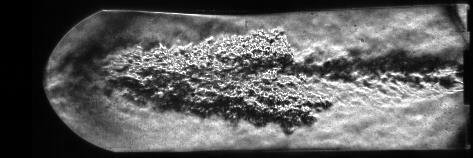
4 The injector mesh consists of 150k nodes. The combustion chamber is meshed with 1.2 Mio nodes for the RCSLaser simulations and with 1.3 Mio nodes for the MOLI simulations Initialization and boundary conditions Preceding each test, the combustion chamber is purged with nitrogen to ensure defined start conditions. Hence, as initial condition of the simulation the combustion chamber and the injector are completely filled with quiescent nitrogen at ambient conditions. The ambient area is defined as air at ambient conditions. The simulation starts with the opening of the first run valve and models the pressure rise in the injector domes and the filling of the combustion chamber with propellants. The energy input of the laser pulse is modeled and the flame development with the pressure peak following the laser ignition are simulated, followed by the relaxation of the combustion chamber pressure to the steady state value. All walls of the injector geometry are treated as adiabatic walls, in the combustion chamber they are defined as isothermal walls at ambient temperature. During ignition this is a valid assumption, as there is not enough time for the flame to heat up the walls. No-slip conditions are applied to all walls. At the outlet boundary of the ambient area opening boundary conditions are applied with ambient pressure and temperature. Pressure is specified as inlet conditions for both the oxygen and methane inlet to achieve the proper mass flow development in time with changing combustion chamber pressure. Methane and oxygen both have the temperature of T = 278 K. The simulations have different cold flow sequences. The opening times of the run valves are set in Tab. 1 as well as the mass flow values at steady flow to show the different conditions. The time of ignition is set as zero. 4. RESULTS AND DISCUSSION Three test cases are compared to get more insight into the flame development under different conditions. Test case A is the RCSLaser test case used in [6]. This test case is compared with two test cases with the MOLI combustion chamber, as shown in Tab. 1. This section will take a look at the differences and similarities of the three tests. To identify some of the main processes leading to hard or soft ignitions, both experimental and numerical results are used. First the flame development following the laser pulse is considered. This part concentrates on experimental data of the optical diagnostics systems. In further steps those observations are compared to the flow conditions and the species distribution in the combustion chamber at the time of ignition. Numerical results are used for these investigations, as no experimental data regarding these values are available Flame development The flame development following the laser pulse defines the heat release and the pressure evolution in the combustion chamber. Information about the flame development is gained by the optical diagnostics systems used in the experimental investigations. Figure 5 shows Schlieren image sequences of the flame development in the three test cases. While the Figure 5: Flame development in the test cases

5 progression of the downstream flame front in the Schlieren images. Test case B has similar cold flow conditions to test case A, in spite of significantly lower mass flow rates and injection velocities of the propellants. Although the time frame is different, the general behavior of the flame is similar for the test cases A and B. In the early stages after the laser pulse the flame speed remains constant at about 75 m/s, before after 0.2 ms the downstream flame front accelerates towards supersonic speeds up to 700 m/s. Figure 6: Evolution of axial flame velocities flame is progressing through the combustion chamber, the flame front is visible in the Schlieren images by the density gradients between cold gases in front of and hot gases behind the flame front. As described in [6], in test case A in the beginning the flame spreads with constant flame velocity in axial direction, but at a certain time the flame front accelerates up to supersonic speeds. This leads to a strong pressure rise in the combustion chamber. The evolution of the axial velocity of the downstream flame front for all three test cases is shown in Fig. 6. These values were derived from the experiments by measuring the frame to frame Test case C shows a significantly different flame development than the other two tests. In the early stages the flame mainly spreads in the shear layer of the main flow in axial direction driven by the flow, without growing in the radial direction on a larger scale. At an axial distance of 38 mm from the faceplate the transition occurs and the flame starts to grow in radial direction as well. The upstream flame front stays at this axial position, until the hot gases from the downstream flame move back upstream in the recirculation zones. Table 2: Axial value of transition point Test case X [mm] A 34 B 46 C 38 Figure 7 shows Schlieren images of the three test cases, where the transition of the flame state is visible. The axial transition position is marked by the red lines. Although the three tests differ in combustion chamber geometry, cold flow conditions and mass flow settings, the axial position of the transition to flame front acceleration and large scale expansion of the flame respectively is very similar for all of them, as shown in Tab Species distribution Figure 7: Transition of flame state in test cases One main influencing factor for the ignition process is the amount and distribution of propellants in the combustion chamber at the time of ignition. As the experiments do not provide data about these properties, numerical simulations allow insights into the situation in the combustion chamber at the
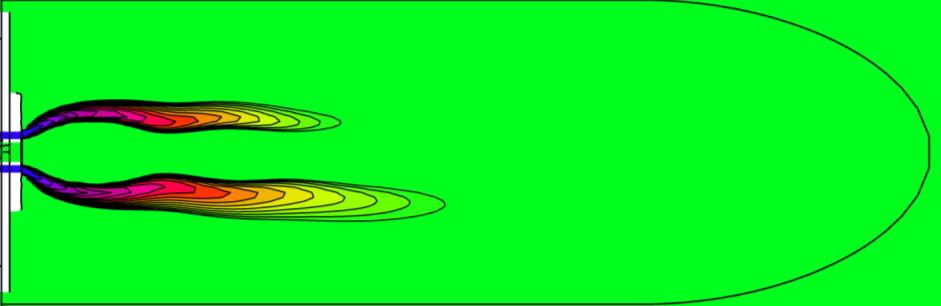
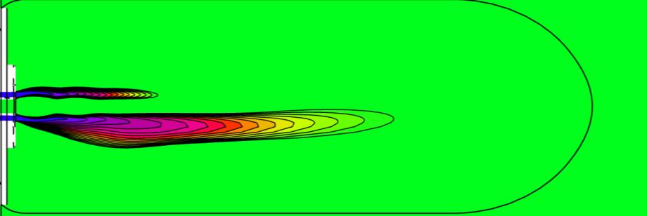
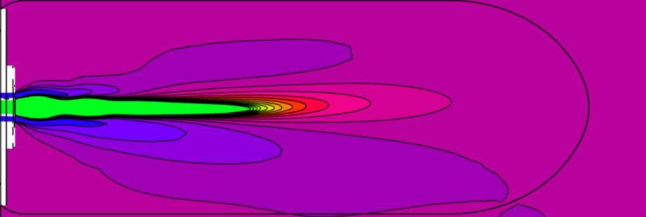
6 time of ignition. In Tab. 3 the global mass fractions of CH 4, O 2 and N 2 are presented for the three tests, averaged by the combustion chamber volume. The Ratio Oxidizer-to-Fuel (ROF) by mass is calculated as well to give an idea about the overall mixture condition in the combustion chamber. The stoichiometric value of CH 4/O 2-mixtures is ROF = 4. Higher values mark lean mixtures with excess of O 2, lower values mark rich mixtures with an excess of CH 4. For the test cases A and B, the overall conditions at the time of ignition are very similar. The ROF is high in both cases, meaning the mixture is O 2-rich. The CH 4 mass fraction is low due to the opening of the run valve only short before ignition. One difference is the N 2 mass fraction. While in test case A only a low amount of N 2 is still present at the time of ignition, test case B still shows a N 2 mass fraction of The mixture here is much more diluted. At test case C the overall situation at time of ignition is different. The amount of CH 4 is four times higher than in the other tests, while the amount of O 2 is less. This leads to a rich mixture with an excess of CH 4 and a ROF of 2.2. Also the N 2 mass fraction is the highest of the three tests, Table 3: Main species mass fractions in the combustion chamber at the time of ignition Test case Mass fraction CH 4 Mass fraction O 2 Mass fraction N 2 Global ROF A B C as because of the short cold flow there is only few time to flush out the N 2 before ignition takes place. The Figures from 8 to 11 show the distribution of propellants on the central xy-plane in the combustion chamber at the time of ignition. The contour plots of the ROF distribution in Fig. 8 capture ROF-values between zero and eight. Values higher than eight are clipped and shown in bright green color, as otherwise the ROF range closer to the stoichiometric value ROF st = 4 and lower is not visible. The test cases A and B show a quite similar situation. The stoichiometric mixtures in these tests are near the CH 4 main flow, while in the recirculation zone a O 2-rich mixture is present. Test case C shows a very different situation. The mixture in the recirculation zone is rich. Near the faceplate stoichiometric mixtures are present only in the shear layer between CH 4 and O 2. Further downstream near stoichiometric mixtures exist in a bigger region when the O 2 main flow mixes with the surrounding fluid. The CH 4 distribution in the combustion chamber, as seen in Fig. 9, shows a similar behavior. The test cases A and B have significant amounts of CH 4 only in the main flow near the injector. Further downstream and in the recirculation zone only low amounts of CH 4 are present. At test case C a high amount of CH 4 is present in all regions of the combustion chamber. The O 2 distribution for all three tests at the time of ignition is shown in Fig. 10. At test case A the combustion chamber is almost completely filled with O 2. The CH 4 flow mixes with the O 2, so in the downstream region of the combustion chamber the amount of O 2 is slightly lower. At test case B the O 2 main flow mixes thoroughly in the downstream part of the combustion chamber and reaches a value of 75 % in the recirculation zones. In test case C the amount of O 2 is lower. The main jet is present in the first part of the combustion chamber, before it mixes with the surrounding fluids. The biggest difference between the tests is the N 2 distribution. In test case A almost all N 2 is flushed out of the combustion chamber, while in the the test cases B and C residual N 2 from the pre-test purging is still present at the time of ignition. Figure 11 shows that N 2 concentrations are higher near the faceplate, indicating a higher dilution of the propellants Discussion The Schlieren images show that a transition of flame development occurs at all three tests. At the test cases A and B an acceleration of the flame front velocity is observed up to supersonic velocities. This leads to high pressure peaks, so called hard ignitions. Test case C shows a transition of the flame from being confined mainly in the shear layer to an expansion on large scale also radially. All three cases show this transition behavior around an axial distance from the faceplate of x = 40 mm. This distance matches the mixing of the main CH 4 (test case A) and O 2 flow (test cases B and C) with the surrounding fluid in the simulations. In the test cases B and C considerable amounts of N 2 are still present at time


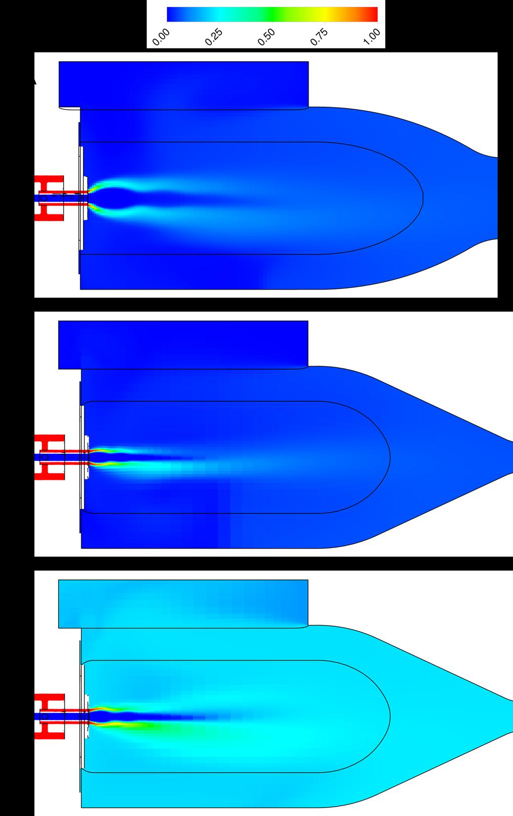
7 Figure 8: ROF distribution in the combustion chamber at the time of ignition Figure 9: CH4 distribution in the combustion chamber at the time of ignition Figure 10: O2 distribution in the combustion chamber at the time of ignition Figure 11: N2 distribution in the combustion chamber at the time of ignition
8 of ignition. No significant influence of the N 2 concentration on the flame development has been observed in the tests, as the flame acceleration takes place in test case B as well as in test case A, where only low amounts of N 2 are left in the combustion chamber at time of ignition. The main difference between the hard ignition test cases A and B and the smooth ignition case C is the O 2 concentration, caused by the different cold flow sequences specified in Tab. 1. The test cases A and B had a similar cold flow setup with long O 2 preflow and short CH 4 preflow, while test case C had a short cold flow with equal preflow times for CH 4 and O 2. While the former show lean mixtures with ROF ~ 20 in the combustion chamber, in the latter case a fuel rich mixture with ROF = 2 is present. These observations lead to the conclusion, that a short and fuel rich cold flow is preferable to achieve a smooth ignition. As the propellants need time to mix, an ignition point downstream the faceplate seems beneficial, around or downstream the transition point at x = 40 mm. Considering the use of cryogenic propellants, this aspect gains relevance, because mixing is more difficult and takes more time, as propellants have to be atomized. 5. SUMMARY Previous investigations with the RCSLaser combustion chamber on CH 4/O 2 laser ignition showed undesirable flame behavior with flame acceleration up to supersonic velocities and hard ignitions. To study the processes leading to hard ignitions tests were done with a new designed combustion chamber with smaller throat diameter. This paper focuses on the flame development observed in these tests and the conditions at the time of ignition, which were obtained by numerical simulations. In the present work three tests have been compared. Test case A, the RCSLaser test, which showed the hard ignition, was compared to two MOLI tests. Test case B had a similar cold flow setup with long O 2 preflow and short CH 4 preflow, while test case C had a short preflow with equal preflow times for CH 4 and O 2. Test case B showed a hard ignition as well, while case C achieved a smooth ignition with low pressure peak. The main difference between the tests is the O 2 concentration in the combustion chamber at the time of ignition. While the test cases A and B have high concentrations of O 2, leading to a lean mixture with ROF ~ 20, test case C shows a low concentration of O 2 and a fuel rich mixture with ROF = 2. In all three tests a transition in the flame development could be observed at a transition point around 40 mm downstream the faceplate. For the test cases A and B from here the flame front starts to accelerate up to supersonic speeds, for test case C the flame starts to spread radially after being confined mainly in the shear layer. This distance matches the mixing of the main CH 4 (test case A) and O 2 flow (test cases B and C) with the surrounding fluid in the simulations, which leads to high amounts of flammable mixture further downstream. The present study indicates that a short cold flow with fuel rich conditions is favorable to achieve a smooth ignition. For laser ignition the ignition point preferably is located at or downstream of the transition point, as there are better ignition conditions due to the better mixing of the propellants. 6. REFERENCES 1. Pauly, C., Sender, J. & Oschwald, M. (2007). Ignition of a Gaseous Methane/Oxygen Coaxial Jet. 2nd European Conference for Aerospace Sciences (EUCASS). 2. Sender, J., Manfletti, C., Oschwald M. & Pauly, C. (2008). Ignition Transients of a gaseous CH4/O2 coaxial jet. 22nd European Conference on Liquid Atomization and Spray Systems. 3. Manfletti, C. & Börner, M. (2014). Ignition Overpressure in Laser Ignited Reaction and Control Thrusters. 50th AIAA/ASME/SAE/ASEE Joint Propulsion Conference 2014, Cologne. 4. Haidn, O., Palkina, I., Riccius, J. & Gernoth, A. (2007). Analysis of a Model Combustor Ignition and Comparison with Experimental Results. 43rd AIAA/ASME/ASEE Joint Propulsion Conference and Exhibit. 5. Wohlhüter, M., Zhukov, V. P. & Manfletti, C. (2014). Numerical Analysis of Laser Ignition and Flame Development in a Subscale Combustion Chamber. Space Propulsion Conference 2014, Cologne. 6. Wohlhüter, M. & Zhukov, V.P. (2015). Numerical analysis of methane/oxygen laser-ignition. 6th European Conference for Aerospace Sciences (EUCASS).
9 7. Börner, M. & Manfletti, C. (2014). Laser Ignition of a multi-injector liquid rocket engine. Space Propulsion Conference 2014, Cologne. 8. ANSYS CFX, ANSYS Academic Research, Release Menter, F.R. (1994). Two-Equation Eddy- Viscosity Turbulence Models for Engineering Applications. AIAA Journal, Vol. 32, No. 8, pp
, Institute of Space")
10 DLR.de Chart 1 Methane/oxygen laser ignition in an experimental rocket combustion chamber: Impact of mixing and ignition position Michael Wohlhüter German Aerospace Center (DLR), Institute of Space Propulsion


11 DLR.de Chart 2 Introduction Hard vs. Smooth ignition B: Hard ignition C: Smooth ignition Original time: 5 ms, fps Video: 10 s, 25 fps


12 DLR.de Chart 3 Review RCSLaser 0,12ms 0,22ms 0,32ms


13 DLR.de Chart 4 Experimental setup Combustion chamber RCSLaser MOLI
14 DLR.de Chart 5 Experimental setup Test bench and measurement systems Combustion chamber: Semicylindrical, diameter d c =60 mm, length l c =140 mm Single coaxial injector Laser ignition system Frequency doubled Nd:YAG laser, λ=532 nm Pulse length 10 ns, pulse energy ~90 mj
15 DLR.de Chart 6 Experimental setup Test bench and measurement systems Combustion chamber: Semicylindrical, diameter d c =60 mm, length l c =140 mm Single coaxial injector Laser ignition system Frequency doubled Nd:YAG laser, λ=532 nm Pulse length 10 ns, pulse energy ~90 mj Optical diagnostics Schlieren camera OH* camera Piezoelectric ( dynamic ) and piezoresistive ( static ) pressure sensors
 Full 3D Mesh: Injector: tetraedral mesh with prism layers, 150 k nodes")
16 DLR.de Chart 7 Numerical setup ANSYS CFX, Version 14.5 URANS turbulence model: Shear Stress Turbulence (SST) Full 3D Mesh: Injector: tetraedral mesh with prism layers, 150 k nodes Combustion chamber: hexaedral mesh RCSLaser: 1.2 Mio nodes MOLI: 1.3 Mio nodes RCSLaser MOLI
17 DLR.de Chart 8 Experimental conditions Test case Combustion chamber Nozzle throat diameter [mm] Ignition position [mm] Valve opening time [ms] Mass flow [g/s] X Y CH 4 O 2 CH 4 O 2 A RCSLaser B MOLI C MOLI

18 DLR.de Chart 9 Experimental Results Flame development A B C 0.1 ms 0.3 ms 0.5 ms
19 DLR.de Chart 10 Experimental Results Flame development A B C 0.1 ms 0.3 ms 0.5 ms

20 DLR.de Chart 11 Numerical results Species distribution A Test case ROF Mass fraction CH 4 Mass fraction O 2 Mass fraction N 2 B A B C C


21 DLR.de Chart 12 A Results Flame transition B C
22 DLR.de Chart 13 Summary Comparison of three laser ignition test cases with two different combustion chambers Experimental investigation of the flame development: flame front acceleration in hard ignition cases Numerical investigation of species distribution at the time of ignition: oxygenrich environment causes hard ignition Transition of flame behaviour occurs when the flame reaches the well mixed propellant zones Fuel rich cold flow conditions and downstream ignition position are beneficial to achieve a smooth ignition Thank you!
23 DLR.de Chart 14 APPENDIX: Additional charts


24 DLR.de Chart 16 Cold flow Experiment vs. Simulation 10 ms 82 ms
25 DLR.de Chart 20 Results Flame development Test cases A and B show flame acceleration Test case C shows opposite behaviour All three test cases show a transition of flame behaviour
26 DLR.de Chart 21 Results Species distribution: ROF ROF st = 4 A ROF-values clipped at ROF = 8 Hard ignition cases: O 2 -rich smooth ignition case: CH 4 -rich B C
27 DLR.de Chart 22 Numerical results Species distribution A Test case ROF Mass fraction CH 4 Mass fraction O 2 Mass fraction N 2 B A B C C

28 DLR.de Chart 26 Results Species distribution: CH 4 Amounts of CH4 low in test cases A and B A High amounts of CH4 in test case C B C
29 DLR.de Chart 23 Numerical results Species distribution A Test case ROF Mass fraction CH 4 Mass fraction O 2 Mass fraction N 2 B A B C C


30 DLR.de Chart 25 Results Species distribution: O 2 Test case A: Close to 100% O2 in large regions Test case B: ~75% O2 in recirculation zones Test case C: ~50% O2 in large regions A B C
31 DLR.de Chart 24 Numerical results Species distribution A Test case ROF Mass fraction CH 4 Mass fraction O 2 Mass fraction N 2 B A B C C


32 DLR.de Chart 27 Results Species distribution: N 2 Test case A: almost no N 2 left A Test case B: still residual N 2 in the chamber Test case C: highest amounts of N 2 B Comparison A and B: N 2 content has no significant impact on the flame development C
Numerical analysis of methane/oxygen laser ignition in a subscale combustion chamber: flame development in simulation and experiment
 6 th EUROPEAN CONFERENCE FOR AEROSPACE SCIENCES Numerical analysis of methane/oxygen laser ignition in a subscale combustion chamber: flame development in simulation and experiment M. Wohlhüter and V.
Numerical simulation of detonation inception in Hydrogen / air mixtures
 Numerical simulation of detonation inception in Hydrogen / air mixtures Ionut PORUMBEL COMOTI Non CO2 Technology Workshop, Berlin, Germany, 08.03.2017 09.03.2017 Introduction Objective: Development of
Effects of Dilution Flow Balance and Double-wall Liner on NOx Emission in Aircraft Gas Turbine Engine Combustors
 Effects of Dilution Flow Balance and Double-wall Liner on NOx Emission in Aircraft Gas Turbine Engine Combustors 9 HIDEKI MORIAI *1 Environmental regulations on aircraft, including NOx emissions, have
Laser ignition of a multi-injector research combustion chamber under high altitude conditions 1
 7 TH EUROPEAN CONFERENCE FOR AERONAUTICS AND SPACE SCIENCES (EUCASS) Laser ignition of a multi-injector research combustion chamber under high altitude conditions 1 Michael Börner* and Chiara Manfletti**
Plasma Assisted Combustion in Complex Flow Environments
 High Fidelity Modeling and Simulation of Plasma Assisted Combustion in Complex Flow Environments Vigor Yang Daniel Guggenheim School of Aerospace Engineering Georgia Institute of Technology Atlanta, Georgia
PERFORMANCE ESTIMATION AND ANALYSIS OF PULSE DETONATION ENGINE WITH DIFFERENT BLOCKAGE RATIOS FOR HYDROGEN-AIR MIXTURE
 PERFORMANCE ESTIMATION AND ANALYSIS OF PULSE DETONATION ENGINE WITH DIFFERENT BLOCKAGE RATIOS FOR HYDROGEN-AIR MIXTURE Nadella Karthik 1, Repaka Ramesh 2, N.V.V.K Chaitanya 3, Linsu Sebastian 4 1,2,3,4
EFFECT OF INJECTION ORIENTATION ON EXHAUST EMISSIONS IN A DI DIESEL ENGINE: THROUGH CFD SIMULATION
 EFFECT OF INJECTION ORIENTATION ON EXHAUST EMISSIONS IN A DI DIESEL ENGINE: THROUGH CFD SIMULATION *P. Manoj Kumar 1, V. Pandurangadu 2, V.V. Pratibha Bharathi 3 and V.V. Naga Deepthi 4 1 Department of
Experimental Investigation of Hot Surface Ignition of Hydrocarbon-Air Mixtures
 Paper # 2D-09 7th US National Technical Meeting of the Combustion Institute Georgia Institute of Technology, Atlanta, GA Mar 20-23, 2011. Topic: Laminar Flames Experimental Investigation of Hot Surface
Numerical Study on the Flow Characteristics of a Solenoid Valve for Industrial Applications
 Numerical Study on the Flow Characteristics of a Solenoid Valve for Industrial Applications TAEWOO KIM 1, SULMIN YANG 2, SANGMO KANG 3 1,2,4 Mechanical Engineering Dong-A University 840 Hadan 2 Dong, Saha-Gu,
Turbostroje 2015 Návrh spojení vysokotlaké a nízkotlaké turbíny. Turbomachinery 2015, Design of HP and LP turbine connection
 Turbostroje 2015 Turbostroje 2015 Návrh spojení vysokotlaké a nízkotlaké turbíny Turbomachinery 2015, Design of HP and LP turbine connection J. Hrabovský 1, J. Klíma 2, V. Prokop 3, M. Komárek 4 Abstract:
ALCOHOL LOX STEAM GENERATOR TEST EXPERIENCE
 ALCOHOL LOX STEAM GENERATOR TEST EXPERIENCE Klaus Schäfer, Michael Dommers DLR, German Aerospace Center, Institute of Space Propulsion D 74239 Hardthausen / Lampoldshausen, Germany Klaus.Schaefer@dlr.de
Experimental Testing of a Rotating Detonation Engine Coupled to Nozzles at Conditions Approaching Flight
 25 th ICDERS August 2 7, 205 Leeds, UK Experimental Testing of a Rotating Detonation Engine Coupled to Nozzles at Conditions Approaching Flight Matthew L. Fotia*, Fred Schauer Air Force Research Laboratory
COMPUTATIONAL FLOW MODEL OF WESTFALL'S 2900 MIXER TO BE USED BY CNRL FOR BITUMEN VISCOSITY CONTROL Report R0. By Kimbal A.
 COMPUTATIONAL FLOW MODEL OF WESTFALL'S 2900 MIXER TO BE USED BY CNRL FOR BITUMEN VISCOSITY CONTROL Report 412509-1R0 By Kimbal A. Hall, PE Submitted to: WESTFALL MANUFACTURING COMPANY May 2012 ALDEN RESEARCH
Combustion characteristics of n-heptane droplets in a horizontal small quartz tube
 Combustion characteristics of n-heptane droplets in a horizontal small quartz tube Junwei Li*, Rong Yao, Zuozhen Qiu, Ningfei Wang School of Aerospace Engineering, Beijing Institute of Technology,Beijing
in ultra-low NOx lean combustion grid plate
 CFD predictions of aerodynamics and mixing in ultra-low NOx lean combustion grid plate flame stabilizer JOSÉ RAMÓN QUIÑONEZ ARCE, DR. ALAN BURNS, PROF. GORDON E. ANDREW S. SCHOOL OF CHEMICAL AND PROCESS
CFD Simulation of Dry Low Nox Turbogas Combustion System
 CFD Simulation of Dry Low Nox Turbogas Combustion System L. Bucchieri - Engin Soft F. Turrini - Fiat Avio CFX Users Conference - Friedrichshafen June 1999 1 Objectives Develop a CFD model for turbogas
Foundations of Thermodynamics and Chemistry. 1 Introduction Preface Model-Building Simulation... 5 References...
 Contents Part I Foundations of Thermodynamics and Chemistry 1 Introduction... 3 1.1 Preface.... 3 1.2 Model-Building... 3 1.3 Simulation... 5 References..... 8 2 Reciprocating Engines... 9 2.1 Energy Conversion...
Marc ZELLAT, Driss ABOURI and Stefano DURANTI CD-adapco
 17 th International Multidimensional Engine User s Meeting at the SAE Congress 2007,April,15,2007 Detroit, MI RECENT ADVANCES IN DIESEL COMBUSTION MODELING: THE ECFM- CLEH COMBUSTION MODEL: A NEW CAPABILITY
NUMERICAL SIMULATION OF COMBUSTION IN A SINGLE ELEMENT H 2 -O 2 CRYOGENIC ENGINE
 ISSN (Online) : 2319-8753 ISSN (Print) : 2347-6710 International Journal of Innovative Research in Science, Engineering and Technology An ISO 3297: 2007 Certified Organization, Volume 2, Special Issue
Numerical Simulation of Gas Turbine Can Combustor Engine
 Numerical Simulation of Gas Turbine Can Combustor Engine CH UMAMAHESHWAR PRAVEEN 1*, A HEMANTH KUMAR YADAV 2 1. Engineer, CDG BOEING Company, Chennai, India. 2. B.Tech Aeronautical Engineer 2012 passout,
Experimental and Numerical Study on the Ignition Process in GOX/CH4 Vortex Thruster
 Experimental and Numerical Study on the Ignition Process in GOX/CH4 Vortex Thruster *De-Chuan Sun 1) and Meng-Cheng Cao 2) 1), 2) School of Aeronautics and Astronautics, Dalian University of Technology,
1. INTRODUCTION 2. EXPERIMENTAL INVESTIGATIONS
 HIGH PRESSURE HYDROGEN INJECTION SYSTEM FOR A LARGE BORE 4 STROKE DIESEL ENGINE: INVESTIGATION OF THE MIXTURE FORMATION WITH LASER-OPTICAL MEASUREMENT TECHNIQUES AND NUMERICAL SIMULATIONS Dipl.-Ing. F.
Scroll Compressor Oil Pump Analysis
 IOP Conference Series: Materials Science and Engineering PAPER OPEN ACCESS Scroll Compressor Oil Pump Analysis To cite this article: S Branch 2015 IOP Conf. Ser.: Mater. Sci. Eng. 90 012033 View the article
Effect of concave plug shape of a control valve on the fluid flow characteristics using computational fluid dynamics
 Effect of concave plug shape of a control valve on the fluid flow characteristics using computational fluid dynamics Yasser Abdel Mohsen, Ashraf Sharara, Basiouny Elsouhily, Hassan Elgamal Mechanical Engineering
Ignition Transient of Supercritical Oxygen/Kerosene Combustion System
 25 th ICDERS August 2 7, 2015 Leeds, UK Ignition Transient of Supercritical Oxygen/Kerosene Combustion System Dohun Kim, Keunwoong Lee Graduate School of Korea Aerospace University Goyang, Gyeonggi, Republic
APPLICATION OF STAR-CCM+ TO TURBOCHARGER MODELING AT BORGWARNER TURBO SYSTEMS
 APPLICATION OF STAR-CCM+ TO TURBOCHARGER MODELING AT BORGWARNER TURBO SYSTEMS BorgWarner: David Grabowska 9th November 2010 CD-adapco: Dean Palfreyman Bob Reynolds Introduction This presentation will focus
Module7:Advanced Combustion Systems and Alternative Powerplants Lecture 32:Stratified Charge Engines
 ADVANCED COMBUSTION SYSTEMS AND ALTERNATIVE POWERPLANTS The Lecture Contains: DIRECT INJECTION STRATIFIED CHARGE (DISC) ENGINES Historical Overview Potential Advantages of DISC Engines DISC Engine Combustion
INFLUENCE OF THE NUMBER OF NOZZLE HOLES ON THE UNBURNED FUEL IN DIESEL ENGINE
 INFLUENCE OF THE NUMBER OF NOZZLE HOLES ON THE UNBURNED FUEL IN DIESEL ENGINE 1. UNIVERSITY OF RUSE, 8, STUDENTSKA STR., 7017 RUSE, BULGARIA 1. Simeon ILIEV ABSTRACT: The objective of this paper is to
Design Rules and Issues with Respect to Rocket Based Combined Cycles
 Respect to Rocket Based Combined Cycles Tetsuo HIRAIWA hiraiwa.tetsuo@jaxa.jp ABSTRACT JAXA Kakuda space center has been studying rocket based combined cycle engine for the future space transportation
HERCULES-2 Project. Deliverable: D8.8
 HERCULES-2 Project Fuel Flexible, Near Zero Emissions, Adaptive Performance Marine Engine Deliverable: D8.8 Study an alternative urea decomposition and mixer / SCR configuration and / or study in extended
University Turbine Systems Research Industrial Fellowship. Southwest Research Institute
 Correlating Induced Flashback with Air- Fuel Mixing Profiles for SoLoNOx Biomass Injector Ryan Ehlig University of California, Irvine Mentor: Raj Patel Supervisor: Ram Srinivasan Department Manager: Andy
Influence of ANSYS FLUENT on Gas Engine Modeling
 Influence of ANSYS FLUENT on Gas Engine Modeling George Martinas, Ovidiu Sorin Cupsa 1, Nicolae Buzbuchi, Andreea Arsenie 2 1 CERONAV 2 Constanta Maritime University Romania georgemartinas@ceronav.ro,
COMPRESSIBLE FLOW ANALYSIS IN A CLUTCH PISTON CHAMBER
 COMPRESSIBLE FLOW ANALYSIS IN A CLUTCH PISTON CHAMBER Masaru SHIMADA*, Hideharu YAMAMOTO* * Hardware System Development Department, R&D Division JATCO Ltd 7-1, Imaizumi, Fuji City, Shizuoka, 417-8585 Japan
Fig 2: Grid arrangements for axis-symmetric Rocket nozzle.
 CFD Analysis of Rocket-Ramjet Combustion Chamber 1 Ms. P.Premalatha, Asst. Prof., PSN College of Engineering and Technology, Tirunelveli. 1prema31194@gmail.com 1 +91-90475 26413 2 Ms. T. Esakkiammal, Student,
Numerical Investigation of the Effect of Excess Air and Thermal Power Variation in a Liquid Fuelled Boiler
 Proceedings of the World Congress on Momentum, Heat and Mass Transfer (MHMT 16) Prague, Czech Republic April 4 5, 2016 Paper No. CSP 105 DOI: 10.11159/csp16.105 Numerical Investigation of the Effect of
Simulation of the Mixture Preparation for an SI Engine using Multi-Component Fuels
 ICE Workshop, STAR Global Conference 2012 March 19-21 2012, Amsterdam Simulation of the Mixture Preparation for an SI Engine using Multi-Component Fuels Michael Heiss, Thomas Lauer Content Introduction
ATOMIZATION AND COMBUSTION IN LOX/H 2 - AND LOX/CH 4 -SPRAY FLAMES. M. Oschwald 1, F. Cuoco 2, B. Yang 3, M. De Rosa 1
 ATOMIZATION AND COMBUSTION IN LOX/H 2 - AND LOX/CH 4 -SPRAY FLAMES M. Oschwald 1, F. Cuoco 2, B. Yang 3, M. De Rosa 1 1 Institute of Space Propulsion DLR Lampoldshausen, German Aerospace Center, 74239
INVESTIGATION OF HEAT TRANSFER CHARACTERISTICS OF CIRCULAR AND DIAMOND PILLARED VANE DISC BRAKE ROTOR USING CFD
 SDRP JOURNAL OF NANOTECHNOLOGY & MATERIAL SCIENCE. INVESTIGATION OF HEAT TRANSFER CHARACTERISTICS OF CIRCULAR AND DIAMOND PILLARED VANE DISC BRAKE ROTOR USING CFD Research AUTHOR: A.RAJESH JUNE 2017 1
Numerical Simulations of a Simultaneous Direct Injection of Liquid And Gaseous Fuels Into a Constant Volume Chamber
 Open Access Journal Journal of Power Technologies 92 (1) (2012) 12 19 journal homepage:papers.itc.pw.edu.pl Numerical Simulations of a Simultaneous Direct Injection of Liquid And Gaseous Fuels Into a Constant
Comparison of Velocity Vector Components in a Di Diesel Engine: Analysis through Cfd Simulation
 IOSR Journal of Mechanical and Civil Engineering (IOSR-JMCE) e-issn: 2278-1684,p-ISSN: 2320-334X PP. 55-60 www.iosrjournals.org Comparison of Velocity Vector Components in a Di Diesel Engine: Analysis
EXTENDED GAS GENERATOR CYCLE
 EXTENDED GAS GENERATOR CYCLE FOR RE-IGNITABLE CRYOGENIC ROCKET PROPULSION SYSTEMS F. Dengel & W. Kitsche Institute of Space Propulsion German Aerospace Center, DLR D-74239 Hardthausen, Germany ABSTRACT
NUMERICAL INVESTIGATION OF FLUID FLOW AND HEAT TRANSFER CHARACTERISTICS ON THE AERODYNAMICS OF VENTILATED DISC BRAKE ROTOR USING CFD
 THERMAL SCIENCE: Year 2014, Vol. 18, No. 2, pp. 667-675 667 NUMERICAL INVESTIGATION OF FLUID FLOW AND HEAT TRANSFER CHARACTERISTICS ON THE AERODYNAMICS OF VENTILATED DISC BRAKE ROTOR USING CFD by Thundil
EFFECTS OF LOCAL AND GENERAL EXHAUST VENTILATION ON CONTROL OF CONTAMINANTS
 Ventilation 1 EFFECTS OF LOCAL AND GENERAL EXHAUST VENTILATION ON CONTROL OF CONTAMINANTS A. Kelsey, R. Batt Health and Safety Laboratory, Buxton, UK British Crown copyright (1) Abstract Many industrial
International Journal of Scientific & Engineering Research, Volume 5, Issue 7, July-2014 ISSN
 ISSN 9-5518 970 College of Engineering Trivandrum Department of Mechanical Engineering arundanam@gmail.com, arjunjk91@gmail.com Abstract This paper investigates the performance of a shock tube with air
Comparison of Swirl, Turbulence Generating Devices in Compression ignition Engine
 Available online atwww.scholarsresearchlibrary.com Archives of Applied Science Research, 2016, 8 (7):31-40 (http://scholarsresearchlibrary.com/archive.html) ISSN 0975-508X CODEN (USA) AASRC9 Comparison
Study on Flow Fields in Variable Area Nozzles for Radial Turbines
 Vol. 4 No. 2 August 27 Study on Fields in Variable Area Nozzles for Radial Turbines TAMAKI Hideaki : Doctor of Engineering, P. E. Jp, Manager, Turbo Machinery Department, Product Development Center, Corporate
Internal Combustion Engines
 Emissions & Air Pollution Lecture 3 1 Outline In this lecture we will discuss emission control strategies: Fuel modifications Engine technology Exhaust gas aftertreatment We will become particularly familiar
Recent enhancement to SI-ICE combustion models: Application to stratified combustion under large EGR rate and lean burn
 Recent enhancement to SI-ICE combustion models: Application to stratified combustion under large EGR rate and lean burn G. Desoutter, A. Desportes, J. Hira, D. Abouri, K.Oberhumer, M. Zellat* TOPICS Introduction
Modeling Constant Volume Chamber Combustion at Diesel Engine Condition
 Modeling Constant Volume Chamber Combustion at Diesel Engine Condition Z. Hu, R.Cracknell*, L.M.T. Somers Combustion Technology Department of Mechanical Engineering Eindhoven University of Technology *Shell
Dual Fuel Engine Charge Motion & Combustion Study
 Dual Fuel Engine Charge Motion & Combustion Study STAR-Global-Conference March 06-08, 2017 Berlin Kamlesh Ghael, Prof. Dr. Sebastian Kaiser (IVG-RF), M. Sc. Felix Rosenthal (IFKM-KIT) Introduction: Operation
POSIBILITIES TO IMPROVED HOMOGENEOUS CHARGE IN INTERNAL COMBUSTION ENGINES, USING C.F.D. PROGRAM
 POSIBILITIES TO IMPROVED HOMOGENEOUS CHARGE IN INTERNAL COMBUSTION ENGINES, USING C.F.D. PROGRAM Alexandru-Bogdan Muntean *, Anghel,Chiru, Ruxandra-Cristina (Dica) Stanescu, Cristian Soimaru Transilvania
Normal vs Abnormal Combustion in SI engine. SI Combustion. Turbulent Combustion
 Turbulent Combustion The motion of the charge in the engine cylinder is always turbulent, when it is reached by the flame front. The charge motion is usually composed by large vortexes, whose length scales
Experiments in a Combustion-Driven Shock Tube with an Area Change
 Accepted for presentation at the 29th International Symposium on Shock Waves. Madison, WI. July 14-19, 2013. Paper #0044 Experiments in a Combustion-Driven Shock Tube with an Area Change B. E. Schmidt
Institut für Thermische Strömungsmaschinen. PDA Measurements of the Stationary Reacting Flow
 Institut für Thermische Strömungsmaschinen Dr.-Ing. Rainer Koch Dipl.-Ing. Tamas Laza DELIVERABLE D2.2 PDA Measurements of the Stationary Reacting Flow CONTRACT N : PROJECT N : ACRONYM: TITLE: TASK 2.1:
Investigation of Direct-Injection via Micro-Porous Injector Nozzle
 Investigation of Direct-Injection via Micro-Porous Injector Nozzle J.J.E. Reijnders, M.D. Boot, C.C.M. Luijten, L.P.H. de Goey Department of Mechanical Engineering, Eindhoven University of Technology,
Australian Journal of Basic and Applied Sciences
 AENSI Journals Australian Journal of Basic and Applied Sciences ISSN:1991-8178 Journal home page: www.ajbasweb.com Efficient and Environmental Friendly NO x Emission Reduction Design of Aero Engine Gas
High Pressure Spray Characterization of Vegetable Oils
 , 23rd Annual Conference on Liquid Atomization and Spray Systems, Brno, Czech Republic, September 2010 Devendra Deshmukh, A. Madan Mohan, T. N. C. Anand and R. V. Ravikrishna Department of Mechanical Engineering
Lecture 4 CFD for Bluff-Body Stabilized Flames
 Lecture 4 CFD for Bluff-Body Stabilized Flames Bluff Body Stabilized flames with or without swirl are in many laboratory combustors Applications to ramjets, laboratory burners, afterburners premixed and
Lecture 27: Principles of Burner Design
 Lecture 27: Principles of Burner Design Contents: How does combustion occur? What is a burner? Mixing of air and gaseous fuel Characteristic features of jet Behavior of free (unconfined) and confined jet
Marc ZELLAT, Driss ABOURI, Thierry CONTE and Riyad HECHAICHI CD-adapco
 16 th International Multidimensional Engine User s Meeting at the SAE Congress 2006,April,06,2006 Detroit, MI RECENT ADVANCES IN SI ENGINE MODELING: A NEW MODEL FOR SPARK AND KNOCK USING A DETAILED CHEMISTRY
Analysis of a turbine rim seal cavity via 3D-CFD using conjugated heat transfer approach
 Analysis of a turbine rim seal cavity via 3D-CFD using conjugated heat transfer approach ZERELLI, N. - Heat Transfer Department MTU Aero Engines, 80995 Munich, Germany University: ISAE Institut Supérieur
Numerical Investigation of the Influence of different Valve Seat Geometries on the In-Cylinder Flow and Combustion in Spark Ignition Engines
 Institute for Combustion and Gas Dynamics Fluid Dynamics Numerical Investigation of the Influence of different Valve Seat Geometries on the In-Cylinder Flow and Combustion in Spark Ignition Engines Peter
Confirmation of paper submission
 Dr. Marina Braun-Unkhoff Institute of Combustion Technology DLR - German Aerospace Centre Pfaffenwaldring 30-40 70569 Stuttgart 28. Mai 14 Confirmation of paper submission Name: Email: Co-author: 2nd co-author:
NUMERICAL INVESTIGATION OF PISTON COOLING USING SINGLE CIRCULAR OIL JET IMPINGEMENT
 NUMERICAL INVESTIGATION OF PISTON COOLING USING SINGLE CIRCULAR OIL JET IMPINGEMENT BALAKRISHNAN RAJU, CFD ANALYSIS ENGINEER, TATA CONSULTANCY SERVICES LTD., BANGALORE ABSTRACT Thermal loading of piston
EXPERIMENTAL STUDIES OF INJECTOR ARRAY CONFIGURATIONS FOR CIRCULAR SCRAMJET COMBUSTORS
 EXPERIMENTAL STUDIES OF INJECTOR ARRAY CONFIGURATIONS FOR CIRCULAR SCRAMJET COMBUSTORS Christopher Rock Graduate Research Assistant and Joseph A. Schetz Advisor, Holder of the Fred D. Durham Chair Department
Effect of Stator Shape on the Performance of Torque Converter
 16 th International Conference on AEROSPACE SCIENCES & AVIATION TECHNOLOGY, ASAT - 16 May 26-28, 2015, E-Mail: asat@mtc.edu.eg Military Technical College, Kobry Elkobbah, Cairo, Egypt Tel : +(202) 24025292
System Simulation for Aftertreatment. LES for Engines
 System Simulation for Aftertreatment LES for Engines Christopher Rutland Engine Research Center University of Wisconsin-Madison Acknowledgements General Motors Research & Development Caterpillar, Inc.
[Rao, 4(7): July, 2015] ISSN: (I2OR), Publication Impact Factor: 3.785
![[Rao, 4(7): July, 2015] ISSN: (I2OR), Publication Impact Factor: 3.785](/thumbs/90/102870037.jpg "[Rao, 4(7): July, 2015] ISSN: (I2OR), Publication Impact Factor: 3.785") IJESRT INTERNATIONAL JOURNAL OF ENGINEERING SCIENCES & RESEARCH TECHNOLOGY CFD ANALYSIS OF GAS COOLER FOR ASSORTED DESIGN PARAMETERS B Nageswara Rao * & K Vijaya Kumar Reddy * Head of Mechanical Department,
IJESRT INTERNATIONAL JOURNAL OF ENGINEERING SCIENCES & RESEARCH TECHNOLOGY CFD ANALYSIS OF GAS COOLER FOR ASSORTED DESIGN PARAMETERS B Nageswara Rao * & K Vijaya Kumar Reddy * Head of Mechanical Department,
CFD ANALYSIS ON LOUVERED FIN
 CFD ANALYSIS ON LOUVERED FIN P.Prasad 1, L.S.V Prasad 2 1Student, M. Tech Thermal Engineering, Andhra University, Visakhapatnam, India 2Professor, Dept. of Mechanical Engineering, Andhra University, Visakhapatnam,
Numerical Simulation of the Effect of 3D Needle Movement on Cavitation and Spray Formation in a Diesel Injector
 Journal of Physics: Conference Series PAPER OPEN ACCESS Numerical Simulation of the Effect of 3D Needle Movement on Cavitation and Spray Formation in a Diesel Injector To cite this article: B Mandumpala
Optical Techniques in Gasoline Engine Performance and Emissions Development Injector Spray Visualisation
 Injector Spray Visualisation Denis Gill, Wolfgang Krankenedl, DEC Ernst Winklhofer 20.03.15 Emissions Development Injector Spray Visualisation Contents Introduction Spray Box Direct Injection (GDI) Spray
CFD Analyses of the Experimental Setup of a Slinger Combustor
 CFD Analyses of the Experimental Setup of a Slinger Combustor Somanath K Bellad 1, 1 M Tech Student, Siddaganga Institute of Technology (SIT), Tumakuru, Karnataka Abstract: An annular combustor with rotating
Transactions on Modelling and Simulation vol 10, 1995 WIT Press, ISSN X
 Flow characteristics behind a butterfly valve M. Makrantonaki," P. Prinos,* A. Goulas' " Department of Agronomy, Faculty of Technological Science, University of Thessalia, Greece * Hydraulics Laboratory,
An Experimental and Numerical Investigation on Characteristics of Methanol and Ethanol Sprays from a Multi-hole DISI Injector
 An Experimental and Numerical Investigation on Characteristics of Methanol and Ethanol Sprays from a Multi-hole DISI Injector Yajia E 1, Min Xu 1, Wei Zeng 1, Yuyin Zhang 1, David J. Cleary 2 1 Inst. of
NUMERICAL AND EXPERIMENTAL INVESTIGATIONS OF LASER IGNITION IN COMBUSTION CHAMBERS
 Sergey G. Rebrov*, Pavel V. Kholodov**, Gyuzel R. Yakhina*** * Keldysh Research Centre Federal State Unitary Enterprise, Moscow, 125438, Russia, ** Moscow Aviation Institute (State University of Aerospace
Investigation of a promising method for liquid hydrocarbons spraying
 Journal of Physics: Conference Series PAPER OPEN ACCESS Investigation of a promising method for liquid hydrocarbons spraying To cite this article: E P Kopyev and E Yu Shadrin 2018 J. Phys.: Conf. Ser.
Supersonic Nozzle Design for 1µm Laser Sources
 Supersonic Nozzle Design for 1µm Laser Sources Ali Khan Bill O Neill Innovative Manufacturing Research Centre (IMRC) Centre for Industrial Photonics Institute for Manufacturing, Department of Engineering,
COMPARISON OF BREAKUP MODELS IN SIMULATION OF SPRAY DEVELOPMENT IN DIRECT INJECTION SI ENGINE
 Journal of KONES Powertrain and Transport, Vol. 17, No. 4 2010 COMPARISON OF BREAKUP MODELS IN SIMULATION OF SPRAY DEVELOPMENT IN DIRECT INJECTION SI ENGINE Przemys aw wikowski, Piotr Jaworski, Andrzej
Improvement of Atomization Characteristics of Spray by Multi-Hole Nozzle for Pressure Atomized Type Injector
 , 23rd Annual Conference on Liquid Atomization and Spray Systems, Brno, Czech Republic, September 2010 Improvement of Atomization Characteristics of Spray by Multi-Hole Nozzle for Pressure Atomized Type
CFD Investigation of Influence of Tube Bundle Cross-Section over Pressure Drop and Heat Transfer Rate
 CFD Investigation of Influence of Tube Bundle Cross-Section over Pressure Drop and Heat Transfer Rate Sandeep M, U Sathishkumar Abstract In this paper, a study of different cross section bundle arrangements
Automatic CFD optimisation of biomass combustion plants. Ali Shiehnejadhesar
 Automatic CFD optimisation of biomass combustion plants Ali Shiehnejadhesar IEA Bioenergy Task 32 workshop Thursday 6 th June 2013 Contents Scope of work Methodology CFD model for biomass grate furnaces
PIV ON THE FLOW IN A CATALYTIC CONVERTER
 PIV ON THE FLOW IN A CATALYTIC CONVERTER APPLICATION NOTE PIV-016 The study and optimization of the flow of exhaust through a catalytic converter is an area of research due to its potential in increasing
CFD Analysis and Comparison of Fluid Flow Through A Single Hole And Multi Hole Orifice Plate
 CFD Analysis and Comparison of Fluid Flow Through A Single Hole And Multi Hole Orifice Plate Malatesh Barki. 1, Ganesha T. 2, Dr. M. C. Math³ 1, 2, 3, Department of Thermal Power Engineering 1, 2, 3 VTU
Combustion Properties of Alternative Liquid Fuels
 1. Prologue Combustion Properties of Alternative Liquid Fuels 21 JULY 211 Cheng Tung Chong, Simone Hochgreb Content 1. Introduction 2. What s biodiesels 3. Burner design and experimental 4. Results - Flame
Analysis of Pre-ignition Initiation Mechanisms using a Multi-Cycle CFD-Simulation
 International Multidimensional Engine Modeling User's Group Meeting 2014 April 7, 2014, Detroit Analysis of Pre-ignition Initiation Mechanisms using a Multi-Cycle CFD-Simulation Michael Heiss, Thomas Lauer
CONJUGATE HEAT TRANSFER ANALYSIS OF HELICAL COIL HEAT EXCHANGE USING CFD
 CONJUGATE HEAT TRANSFER ANALYSIS OF HELICAL COIL HEAT EXCHANGE USING CFD Rudragouda R Patil 1, V Santosh Kumar 2, R Harish 3, Santosh S Ghorpade 4 1,3,4 Assistant Professor, Mechanical Department, Jayamukhi
IAC-15-C4.3.1 JET INDUCER FOR A TURBO PUMP OF A LIQUID ROCKET ENGINE
 IAC-15-C4.3.1 JET INDUCER FOR A TURBO PUMP OF A LIQUID ROCKET ENGINE Martin Böhle Technical University Kaiserslautern, Germany, martin.boehle@mv.uni-kl.de Wolfgang Kitsche German Aerospace Center (DLR),
injection on a cold start system
 CFD analysis of fuel injection on a cold start system CFD analysis of fuel injection on a cold start system Martin Kessler Regis Ataides Victor Arume de Souza Cesareo de La Rosa Siqueira Alessandro F.
Experimental Verification of Low Emission Combustor Technology at DLR
 www.dlr.de Chart 1 > FORUM-AE Non-CO2 mitigation technology Workshop> Hassa > 2.7.2014 Experimental Verification of Low Emission Combustor Technology at DLR Christoph Hassa Institute of Propulsion Technology
Paper ID ICLASS EXPERIMENTAL INVESTIGATION OF SPRAY IMPINGEMENT ON A RAPIDLY ROTATING CYLINDER WALL
 ICLASS-26 Aug.27-Sept.1, 26, Kyoto, Japan Paper ID ICLASS6-142 EXPERIMENTAL INVESTIGATION OF SPRAY IMPINGEMENT ON A RAPIDLY ROTATING CYLINDER WALL Osman Kurt 1 and Günther Schulte 2 1 Ph.D. Student, University
Theoretical and Experimental Discourse on Laser Ignition in Liquid Rocket Engines
 Theoretical and Experimental Discourse on Laser Ignition in Liquid Rocket Engines By Chiara Manfletti, Michael Oschwald and Joachim Sender Institute of Space Propulsion, German Aerospace Center (DLR),
Module 2:Genesis and Mechanism of Formation of Engine Emissions Lecture 9:Mechanisms of HC Formation in SI Engines... contd.
 Mechanisms of HC Formation in SI Engines... contd. The Lecture Contains: HC from Lubricating Oil Film Combustion Chamber Deposits HC Mixture Quality and In-Cylinder Liquid Fuel HC from Misfired Combustion
Engineering Success by Application of STAR-CCM+ for Modern Gas Turbine Design
 STAR Japanese Conference 2013 December 3, Yokohama, Japan Engineering Success by Application of STAR-CCM+ for Modern Gas Turbine Design Norbert Moritz, Karsten Kusterer, René Braun, Anis Haj Ayed B&B-AGEMA
A Study of EGR Stratification in an Engine Cylinder
 A Study of EGR Stratification in an Engine Cylinder Bassem Ramadan Kettering University ABSTRACT One strategy to decrease the amount of oxides of nitrogen formed and emitted from certain combustion devices,
NUMERICAL INVESTIGATION OF EFFECT OF EXHAUST GAS RECIRCULATION ON COMPRESSIONIGNITION ENGINE EMISSIONS
 ISSN (Online) : 2319-8753 ISSN (Print) : 2347-6710 International Journal of Innovative Research in Science, Engineering and Technology An ISO 3297: 2007 Certified Organization, Volume 2, Special Issue
Premixed Tulip Shaped Flames in a Rectangular Combustion Chamber
 Paper # 120 Topic: Laminar Flames 8 th U. S. National Combustion Meeting Organized by the Western States Section of the Combustion Institute and hosted by the University of Utah May 19-22, 2013 Premixed
Mixture Preparation in a Small Engine Carburator
 Mixture Preparation in a Small Engine Carburator Peter Dittrich, Frank Peter MBtech Powertrain GmbH, Germany ABSTRACT The objective of this work is related to the problem of mixture preparation in a carburator
Metrovick F2/4 Beryl. Turbo-Union RB199
 Turbo-Union RB199 Metrovick F2/4 Beryl Development of the F2, the first British axial flow turbo-jet, began in f 940. After initial flight trials in the tail of an Avro Lancaster, two F2s were installed
Numerically Analysing the Effect of EGR on Emissions of DI Diesel Engine Having Toroidal Combustion Chamber Geometry
 Numerically Analysing the Effect of EGR on Emissions of DI Diesel Engine Having Toroidal Combustion Chamber Geometry Jibin Alex 1, Biju Cherian Abraham 2 1 Student, Dept. of Mechanical Engineering, M A
Finite Element Analysis on Thermal Effect of the Vehicle Engine
 Proceedings of MUCEET2009 Malaysian Technical Universities Conference on Engineering and Technology June 20~22, 2009, MS Garden, Kuantan, Pahang, Malaysia Finite Element Analysis on Thermal Effect of the