AE 1005 AUTOMOTIVE ENGINES COMBUSTION IN SI ENGINES
|
|
|
- Frederick Flynn
- 5 years ago
- Views:
Transcription
1 AE 1005 AUTOMOTIVE ENGINES COMBUSTION IN SI ENGINES
2 Syllabus Combustion in premixed and diffusion flames - Combustion process in IC engines. Stages of combustion - Flame propagation - Flame velocity and area of flame front - Rate of pressure rise - Cycle to cycle variation - Abnormal combustion - Theories of detonation - Effect of engine operating variables on combustion. Combustion chambers - types, factors controlling combustion chamber design.
3 COMBUSTION MODES AND FLAME TYPES Premixed flames: If the fuel and oxidizer are essentially uniformly mixed together, the flame is designated as premixed. The conventional spark-ignition flame is thus a premixed unsteady turbulent flame, and the fuel-air mixture through which the flame propagates is in the gaseous state. Diffusion flames: If the reactants are not premixed and must mix together in the same region where reaction takes place, the flame is called a diffusion flame. The diesel engine combustion process is predominantly an unsteady turbulent diffusion flame, and the fuel is initially in the liquid phase.
4 Combustion is defined as a rapid chemical combination of hydrogen and carbon in fuel with oxygen in air resulting in liberation of energy in the form of heat. Following conditions are necessary for combustion to take place 1. The presence of combustible mixture 2. Some means to initiate mixture 3. Stabilization and propagation of flame in Combustion Chamber In S I Engines, carburetor supplies a combustible mixture of petrol and air and spark plug initiates combustion
5 The fuel and air are homogeneously mixed together in the intake system. Inducted through the intake valve into the cylinder where it mixes with residual gases and is then compressed. Combustion is initiated towards the end of the compression stroke at the spark plug by an electric discharge. A flame develops and propagates through this premixed charge of fuel and air and also the residual gas in the clearance volume until it reached the combustion chamber wall. Combustion is divided into Normal and abnormal combustion.
6 IGNITION LIMITS Ignition of charge is only possible within certain limits of fuel-air ratio. Ignition limits correspond approximately to those mixture ratios, at lean and rich ends of scale, where heat released by spark is no longer sufficient to initiate combustion in neighbouring unburnt mixture. For hydrocarbons fuel the stoichiometric fuel air ratio is 1:15 and the ignition limit is 1:30 and 1:7 (Fuel Air)
7 THEORIES OF COMBUSTION IN SI ENGINE Combustion in SI engine may be roughly divided into two general types: Normal and Abnormal(knock free or Knocking). Inthediagram,atobiscompressionprocess,btociscombustion processandctodistheexpansionprocess. In an ideal cycle it can be seen from the diagram, the entire pressure rise during combustion takes place at constant volume i.e., at TDC. In actual cycle this does not happen.
8 RICARDO S THEORY OF COMBUSTION According to Sir Ricardo, (father of engine research) combustion process can be imagined as if it is developing in two stages: 1. Growth and development of a self propagating nucleus flame. ( Ignition lag) 2. Spread of flame through the combustion chamber
9 STAGE OF COMBUSTION There are three stages of combustion in SI Engines, 1. Ignition lag 2. Flame propagation 3. After burning
10 1. Ignition lag There is a certain time interval between instant of spark and instant where there is a noticeable rise in pressure due to combustion. This time lag is called IGNITION LAG.
11 Ignition lag During ignition lag, molecules get heated up to self ignition temperature (chemical reactions), get ignited and produce a self propagating nucleus of flame. The ignition lag is generally expressed in terms of crank angle (θ1). The period of ignition lag is shown by path A to B. Ignition lag lies between to seconds. An ignition lag of second corresponds to 35 crank rotation when the engine is running at 3000 RPM. Angle of advance increase with the speed. This is a chemical process depending upon the nature of fuel, temperature and pressure, proportions of exhaust gas and rate of oxidation or burning.
12 2. Flame propagation Once the flame is formed, it should be self sustained and must be able to propagate through the mixture. This is possible when the rate of heat generation by burning is greater than the heat lost by flame to surrounding. After the point B, the flame propagation is slow at the beginning as heat lost is more than heat generated. Pressure rise is slow as mass of mixture burned is small. Therefore it is necessary to provide angle of advance 30 to 35, if the peak pressure is to be attained 5-10 ATDC. The time required for the crank to rotate through an angle θ 2 is known as combustion period during which propagation of flame takes place.
13 3. After burning Combustion will not stop at point C but continue after attaining peak pressure and this combustion is known as after burning.
14 FLAME FRONT PROPAGATION Two important factors which determine the rate of movement of the flame front across the combustion chamber are the Reaction rate and Transposition rate. Reaction rate is the result of a purely chemical combination process in which the flame eats its way into the unburned charge. Transposition rate is due to the physical movement of the flame front relative to the cylinder wall and is also the result of the pressure differential between the burning gases and the unburnt gases in the combustion chamber.
15 FLAME FRONT PROPAGATION
16 Flame Velocity
17 FLAME FRONT PROPAGATION Area I, (AB) Flame front progresses relatively slow due to a low transposition rate and low turbulance. Transposition rate is low because there is a comparatively small mass of charge burned at the start. There is a lack of turbulence due to spark plug is located close to the cylinder wall (i.e. in quiescent layer of gas). Thus turbulence reduce the reaction rate, thus the flame speed is reduced.
18 FLAME FRONT PROPAGATION Area II, (BC): The flame leaves the quiescent zone and proceeds into more turbulence area (area II). Flame consumes a greater mass of mixture, it progresses more rapidly and at a constant rate. Area III, (CD): Transposition rate again becomes negligible. As the volume of unburned charge is very less towards the end of flame travel, the flame speed is reduced. Reaction rate also reduced since the flame enter into low turbulence zone.
19 Effect of Engine Variables on Flame Propagation 1.Fuel-air ratio: When the mixture is made learner or rich, the velocity of flame diminishes.
20 Effect of Engine Variables on Flame Propagation 2. Compression ratio: The speed of combustion increases with increase of CR. The increase in CR results in increase in temperature which increases the tendency of the engine to detonate. 3. Intake temperature & pressure: Increase in intake temperature and pressure increases the flame speed.
21 Effect of Engine Variables on Flame Propagation 4. Engine load: As the load on the engine increases, the cycle pressure increases and hence the flame speed increases. 5. Turbulence: The flame speed is low in non-turbulent mixture. Turbulent motion intensifies the processes of heat transfer and mixing of the burnt and unburnt portions in the flame front. These two factors cause the velocity of turbulent flame to increase in proportion to the turbulent velocity.
22 Effect of Engine Variables on Flame Propagation 6. Engine speed: The flame speed increases almost linearly with engine speed. The crank angle required for flame propagation, which is the main phase of combustion, will remain almost constant at all speeds. 7. Engine size: The number of crank degrees required for flame travel will be about the same irrespective of engine size, provided the engines are similar.
23 RATE OF PRESSURE RISE: The rate of pressure rise in the combustion chamber influences the peak pressure developed, the power produced and smoothness in operation. The rate of pressure rise is mainly dependent upon the rate of combustion of mixture. P-θ diagram for three different combustion rates is shown in the figure. 1) Curve I High combustion rate. 2) Curve II Normal combustion rate. 3) Curve III Low combustion rate.
24 RATE OF PRESSURE RISE
25 RATE OF PRESSURE RISE High combustion rate (Curve I) High rate of combustion results in high rate of pressure rise. It produces higher peak pressures at a point closer to TDC. This is desirable because high peak pressure closer to TDC produce more force acting through larger part of the power stroke, increasing the power output of the engine. Higher rate of pressure rise causes rough running of the engine because of vibrations produced in the crank shaft. This tends to knocking.
26 RATE OF PRESSURE RISE Normal combustion rate (Curve II) A compromise between these opposing factors is accomplished by designing and operating the engine approximately one-half of the maximum pressure is reached by the time the piston reaches TDC. This result in the peak pressure being reasonably close to the TDC, yet maintaining smooth engine operation.
27 RATE OF PRESSURE RISE Low combustion rate (Curve III) Low rate of combustion requires long time to complete combustion. It initiates the burning at an early point on the compression stroke and the peak pressure occurs very late. This will result in poor power output of the engine.
28 Factors affecting normal combustions in S.I. engines 1. Induction pressure. Less induction pressure - ignition lag increases - ignition must be advanced - vacuum control 2. Engine speed. Speed increases - constant time ignition lag needs more crank angle - ignition must be advanced - Centrifugal advance 3. Ignition timing. Ignition too early - peak pressure will occur too early and work done falls. Ignition too late - peak pressure will be low and work done falls. Combustion is not complete when exhaust valve opens and the valve may also burn.
29 Factors affecting normal combustions in S.I. engines 4.Mixture strength. Stoichiometric ratio should give best combustion. Dissociation demands a slightly rich mixture necessary for maximum work transfer. Lean
30 Factors affecting normal combustions in S.I. engines 5. Compression ratio. Increase in compression ratio - increases the maximum pressure and the work transfer. 6. Combustion chamber. The combustion chamber Design - short flame path to avoid knock - promote optimum turbulence. 7. Fuel choice. Calorific value and enthalpy of vaporization affects the temperatures achieved.
31 EFFECT OF ENGINE VARIABLES ON IGNITION LAG Ignition lag is not a period of inactivity but is the duration of pre flame reactions The ignition lag in terms of crank angles is 10 to 20 and in terms of time, to sec 1. Fuel. Ignition lag depends on chemical nature of fuel. The higher the self ignition temperature of fuel, longer the ignition lag. 2. Mixture ratio. Ignition lag is the smallest for the mixture ratio which gives the maximum temperature. This mixture ratio is slightly richer than stoichiometric ratio.
32 EFFECT OF ENGINE VARIABLES ON IGNITION LAG 3. Initial temperature and pressure. Ignition lag is reduced if the initial temperature and pressure are increased. These can also be increased by increasing the compression ratio. 4. Turbulence. Ignition lag is not much affected by the turbulence.
33 WHY SPARK ADVANCE? In order to obtain maximum power from an engine, the compressed charge (burning) must deliver maximum pressure at a time when the piston is about to start the expansion stroke. Since there is an ignition lag, the spark must take place before the piston reaches T.D.C. on its compression stroke, i.e., the spark timing is advanced. Usually the spark advance is about 15 BTDC
34 FACTORS AFFECTING IGNITION TIMING
35 FACTORS AFFECTING IGNITION TIMING 2. Mixture strength. In general rich mixtures burn faster. If the engine is operating with rich mixtures the spark timings must be retarded, i.e., the number of crank angle BTDC at the time of ignition is decreased and the spark occurs closer to TDC.
36 FACTORS AFFECTING IGNITION TIMING 3. Part-load operation. Part-load operation of a spark-ignition engine is affected by throttling the incoming charge. Due to throttling a small amount of charge enters the cylinder, and the dilution due to residual gases is also greater. In order to overcome the problem of exhaust gas dilution and the low charge density, at part-load operation the spark advance must be increased.
37 FACTORS AFFECTING IGNITION TIMING 4. Type of fuel. Ignition delay will depend upon the type of fuel used in the engine. For maximum power and economy a slow burning fuel needs a higher spark advance than a fast burning fuel.
38 ABNORMAL COMBUSTION There are two combustion abnormalities, 1. Pre orpost ignition This is the ignition of the mixture by incandescent carbon particles in the chamber. This will have the effect of reducing the work transfer. 2. Knock This is a complex condition with many facets. Knock occurs when the unburnt portion of the gas in the combustion chamber is heated by combustion and radiation so that its temperature becomes greater than the self ignition temperature.
39 ABNORMAL COMBUSTION Contd If normal combustion is not completed before the end of the induction period then a simultaneous explosion of the unburnt gas will occur. This explosion is accompanied by a detonation wave which will be repeatedly reflected from the cylinder walls setting up a high frequency resonance which gives an audible noise. The detonation wave causes excessive stress and also destroys the thermal boundary layer at the cylinder walls causing overheating.
40 PRE-IGNITION Pre-ignition is the ignition of the homogeneous mixture in the cylinder, before the timed spark occurs, caused by the local overheating of the combustible mixture. For premature ignition of any local hot-spot to occur in advance of the timed spark on the combustion stroke it must attain a temperature of C. Pre-ignition is initiated by some overheated projecting part such as the sparking plug electrode, exhaust valve head, metal corners in the combustion chamber, carbon deposits or protruding cylinder head gasket rim etc.
41 PRE-IGNITION The initiation of ignition and the propagation of the flame front from the heated hotspot is similar to that produced by the spark-plug when it fires, the only difference between the hot-spot and spark plug is their respective instant of ignition. The spark plugs provides a timed and controlled moment of ignition whereas the heated surface forming the hot-spot builds up to the ignition temperature during each compression stroke and therefore the actual instant of ignition is unpredictable.
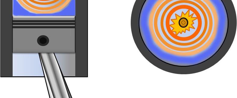
42 1 A Normal Combustion B Detonation C Pre-Ignition 2 3 4
43 PRE-IGNITION Ignition created by pre-ignition extends the total time the burnt gases remain in the cylinder and increases the heat transfer to the chamber walls, resulting in the selfignition temperature occuring earlier and earlier on each successive compression stroke. Peak cylinder pressure (which occurs at ATDC) will progressively advance towards TDC where the cylinder pressure and temperature are maximum.
44 PRE-IGNITION The accumulated effects of an extended combustion time, rising peak cylinder pressure and temperature cause the mixture to attain self-ignition temperature much ahead of TDC. Peak cylinder pressure will now take place BTDC so that negative work will be done in compressing the combustion products.
45 PRE-IGNITION Cylinder pressure variation with Pre- Ignition
46 ABNORMAL COMBUSTION Normally, the flame initiated by the spark travels across the combustion chamber in a uniform manner. Under certain operating conditions, the combustion deviates from its normal course leading to loss of performance and possible damage to the engine. This type of combustion is termed as Abnormal combustion or knocking combustion. The consequences of abnormal combustion process are the loss of power, recurring pre-ignition and mechanical damage to the engine.
47 NORMAL & ABNORMAL COMBUSTION

48 NORMAL & ABNORMAL COMBUSTION
49 NORMAL & ABNORMAL COMBUSTION Autoignitiontheory holds when fuel-air mixture in the end-gas region is compressed to sufficiently high p and T, the fuel oxidation process - starting with the preflame chemistry and ending with rapid energy release - can occur spontaneously in parts or all of the end-gas region. Detonation theory postulates that under knocking conditions, advancing flame front accelerates to sonic velocity and consumes the end-gas at a rate much faster than would occur with normal flame speeds.
50 PROCESS OF DETONATION OR KNOCKING Refer Fig c and d. Flame advances from the spark plug location A. This flame front compresses the end charge BB D farthest from the spark plug raising its temperature. The temperature of the end charge also increases due to heat transfer from the hot advancing flame front. Some preflame oxidation may take place in end charge leading to further increase in its temperature.
51 PROCESS OF DETONATION OR KNOCKING If the end charge reaches its auto-ignition temperature and remains for some time to complete the preflame reactions, the charge will autoignite leading to knocking combustion. During the preflame reaction period the flame front could move from BB to CC, and the knock occurs due to auto-ignition of the charge ahead of CC. Here we have combustion unaccompanied by flame, producing a very high rate of pressure rise.
52 PROCESS OF DETONATION OR KNOCKING The intensity of detonation will depend mainly upon the amount of energy contained in the end-mixture and the rate of chemical reaction which releases it in the form of heat and a high intensity pressure-wave. Thus, the earlier in the combustion process the detonation commences, the more unburnt end-mixture will be available to intensify the detonation. As little as 5 per cent of the total mixture charge when spontaneously ignited will be sufficient to produce a very violent knock.
53 SYMPTOMS WHICH CAN HELP TO IDENTIFY THE KNOCK Metallic sound in harmony with engine firing Sound comes out after long running Sound disappears at idle speed Drastic drop in fuel efficiency Drop in power output Engine run with high temperature and noise
54 KNOCK Damaged Components
55 SI Engine Combustion Chamber
56 Combustion Chamber In diesel and gasoline engines the enclosed space where the combustion of the fuel takes place is called the combustion chamber. It is an enclosed volume bound between the cylinder head and the top of the piston. The layout and the shape of the combustion chamber depend on the profile of the piston top, the shape of the cylinder head, the location and the arrangements of the inlet and exhaust valves, and the spark plugs.
57 Combustion Chamber The design of the combustion chamber influences the performance of the engine and its anti-knock properties. The layout and shape of the combustion chamber has a bearing on the thermal efficiency and performance as well, thus different types of combustion chambers have been designed and used over the years (and still the research is on). It must be noted that the design of the combustion chamber is different for the spark ignition and compression ignition engines.
58 Basic requirements of a good High Power Output combustion Chamber High thermal efficiency and low specific fuel consumption Smooth engine operation Reduced exhaust pollutants
59 High Power Output A high compression ratio A little rich mixture Good Turbulence Large inlet valve to achieve good Volumetric Efficiency Streamline flow in order to reduce the pressure drop and to increase the volumetric efficiency further
60 High thermal efficiency and low specific fuel consumption A high compression ratio A small heat loss during combustion, which means a small surface to volume ratio and a compact shape Faster fuel burning process A little lean mixture
61 Smooth engine operation A moderate rate of pressure rise during combustion Absence of knock, which in turn means, A compact combustion chamber to reduce flame travel distance Proper location of spark plug, exhaust valve and their cooling
62 Reduced exhaust pollutants Exhaust pollutants can be reduced by designing a combustion chamber that produces a faster burning rate of fuel. A faster burning chamber with its shorter burning time permits operation with higher EGR, which reduces NOx in the exhaust gas without substantial increase in HC emissions. Locating the spark plug to a most central position with in a compact combustion chamber Using two spark plugs Increasing the in-cylinder gas motion by creating swirl during the induction process or during the latter stages of compression
63 Principle of Combustion Chamber Design No matter what new innovation the automobile companies claim to have made or any new radical design developed, the principles of combustion chamber design are the same: The inlet valve should be as large as possible to achieve a high volumetric efficiency. The length the flame has to travel should be as short as possible to avoid detonation of the charge. This would involve the design of the combustion chamber, the location of the spark plugs, and installation of multiple spark plugs to start multiple flame fronts. Hot spots that can cause pre-ignition should be avoided by cooling and the location of the spark plug and the exhaust valve. A smaller area of the exhaust valve would offer less chance of hot spots. The small area can be compensated by increasing the
64 Principle of Combustion Chamber Design An optimum degree of turbulence should be provided so that the velocity of the flame propagation is the highest. This would decrease the combustion time and increase the thermal efficiency. Cooling has to be optimum, a high degree of cooling would reduce the thermal efficiency and low cooling could lead to preignition or material failure. The surface to volume ratio should be least so that loss of heat is avoided and we can get a high thermal efficiency. According to the grade of the fuel used the highest compression ratio should be used to increase the thermal efficiency. Scavenging must be efficient to reduce exhaust gas dilution.
65 COMBUSTION CHAMBER DESIGN PRINCIPLES 1. High Volumetric Efficiency More charge per stroke and a proportionate increase in power output Effective valve open area, which depends on valve diameter and lift To reduce pumping losses, valve head should be large (Valve size depends upon head geometry)
66 2. Minimum path of Flame Travel Determined by location of spark plug and shape of the combustion chamber A compact CC reduces flame travel With a little turbulence, this reduces the time of combustion and minimises the burning time losses. Minimum flame travel distance also reduces the knocking tendency SI engine cylinder bore is limited to 100mm
67 3. Provision of minimum heat loss zone around the spark plug This ensures good initial combustion conditions The spark plug is placed near the exhaust valve to reduce heat loss at the first phase of combustion Surface to volume ratio should be minimum
68 4. Reduced rate of pressure rise The second phase of combustion zone should be designed to give a reduced rate of prssure rise to avoid knocking and to avoid excessive shocks on the crankshaft
69 5. Provision of a suitable quench region Quench region is provided at the farthest distance of flame travel so that cooling of the air-fuel mixture during the most likely knocking period occurs This can be achieved by making the surface to volume ratio high at this location Keeping the cool inlet valve at this location also helps
70 6. Maximum Thermal Efficiency Maximum thermal efficiency can be achieved by using the highest compression ratio possible for that fuel for smooth engine operation without knocking tendency under all operating conditions.
71 7. Short combustion time or Fast burn This is a very important point to be considered Short combustion duration can be achieved by creating turbulence. Turbulence helps lean combustion, thus reducing air pollution Proper air movement can be created by positioning the inlet valve suitably
72 Combustion Chamber Types T Head Combustion Chamber: This was used in Ford famous model T car. It was however very successful as it had two cam shafts and the prone to detonation even at a low compression ratio of 4:1. In this T head combustion chamber both the inlet and the exhaust valves are located at the opposite types of the combustion chamber. This type of combustion chamber was common as it those days the fuel available was of octane rating about 45 and highly prone to self igniting. A far and isolated exhaust valve lead to fewer self ignitions.
73 I Head Combustion Chamber: These were also called Side Valve Combustion Chambers or Flat-heads, and both the inlet and the exhaust valves were placed on side of the engine together. This type of the engine was easier to manufacture and the maintenance was also easy as the complete valve block could be removed for overhaul. However it was prone to detonation as large flame length was large and the air had to take two right turns to reach the combustion space resulting in less turbulence.
74 F Head Combustion Chamber: In this type of combustion chamber one valve is located in the side pockets and the other is located in the cylinder head. The F head type engine was better than the T head engine but the valve operating mechanism was a bit complicated.
75 This is a modification of T head combustion chamber. In this type, both inlet and exhaust valves are provided on the same side of the cylinder and are opened by tappets actuated by a single camshaft. It is easy to lubricate the valve mechanism with a detachable head. Cylinder head can be removed for cleaning without disturbing the valves.
76
77
78 HEMI Design
79 What is a Hemispherical Combustion Chamber A hemispherical combustion chamber, also known as the HEMI, has a combustion chamber in the shape of a half sphere. The hemispherical combustion chamber has an advantage of cross flow design that allows the engine to breathe better. The hemispherical engines are in use from the early 1900 s and were widely used. The newer style hemispherical combustion chamber is not a true hemisphere but a partial hemisphere. This modification is to give some turbulence to the engine.
80 What is a Hemispherical Combustion Chamber The hemispherical combustion chamber generates more power as the air does not have to turn at right angles and the resistance to its motion is less. However emission problems are more on a hemispherical combustion chamber and hence the new HEMI are only partially hemispherical. The key advantage of a hemispherical combustion chamber is that its surface area to volume ratio is the least in the category a compared to other designs like flat head, wedge heads, etc. and therefore they have a superior thermal efficiency than other engines. Also, as the valves are located cross-wise, the valves can be made large resulting in better scavenging or breathing of the engine.
81 THANK YOU
Normal vs Abnormal Combustion in SI engine. SI Combustion. Turbulent Combustion
 Turbulent Combustion The motion of the charge in the engine cylinder is always turbulent, when it is reached by the flame front. The charge motion is usually composed by large vortexes, whose length scales
COMBUSTION in SI ENGINES
 Internal Combustion Engines MAK 493E COMBUSTION in SI ENGINES Prof.Dr. Cem Soruşbay Istanbul Technical University Internal Combustion Engines MAK 493E Combustion in SI Engines Introduction Classification
COMBUSTION in SI ENGINES
 Internal Combustion Engines ME422 COMBUSTION in SI ENGINES Prof.Dr. Cem Soruşbay Internal Combustion Engines Combustion in SI Engines Introduction Classification of the combustion process Normal combustion
ACTUAL CYCLE. Actual engine cycle
 1 ACTUAL CYCLE Actual engine cycle Introduction 2 Ideal Gas Cycle (Air Standard Cycle) Idealized processes Idealize working Fluid Fuel-Air Cycle Idealized Processes Accurate Working Fluid Model Actual
Alternative Fuels & Advance in IC Engines
 Alternative Fuels & Advance in IC Engines IIT Kanpur Kanpur, India (208016) Combustion in SI Engine Course Instructor Dr. Avinash Kumar Agarwal Professor Department of Mechanical Engineering Indian Institute
Module 3: Influence of Engine Design and Operating Parameters on Emissions Lecture 14:Effect of SI Engine Design and Operating Variables on Emissions
 Module 3: Influence of Engine Design and Operating Parameters on Emissions Effect of SI Engine Design and Operating Variables on Emissions The Lecture Contains: SI Engine Variables and Emissions Compression
Chapter 4 ANALYTICAL WORK: COMBUSTION MODELING
 a 4.3.4 Effect of various parameters on combustion in IC engines: Compression ratio: A higher compression ratio increases the pressure and temperature of the working mixture which reduce the initial preparation
Combustion. T Alrayyes
 Combustion T Alrayyes Fluid motion with combustion chamber Turbulence Swirl SQUISH AND TUMBLE Combustion in SI Engines Introduction The combustion in SI engines inside the engine can be divided into three
Lecture 5. Abnormal Combustion
 Lecture 5 Abnormal Combustion Abnormal Combustion The Abnormal Combustion:- When the combustion gets deviated from the normal behavior resulting loss of performance or damage to the engine. It is happened
Module7:Advanced Combustion Systems and Alternative Powerplants Lecture 32:Stratified Charge Engines
 ADVANCED COMBUSTION SYSTEMS AND ALTERNATIVE POWERPLANTS The Lecture Contains: DIRECT INJECTION STRATIFIED CHARGE (DISC) ENGINES Historical Overview Potential Advantages of DISC Engines DISC Engine Combustion
Dr Ali Jawarneh Department of Mechanical Engineering
 Chapter 7: Combustion Dr Ali Jawarneh Department of Mechanical Engineering Hashemite University Outline In this lecture we will discuss the combustion process: The characteristics of the process. The different
LECTURE NOTES INTERNAL COMBUSTION ENGINES SI AN INTEGRATED EVALUATION
 LECTURE NOTES on INTERNAL COMBUSTION ENGINES SI AN INTEGRATED EVALUATION Integrated Master Course on Mechanical Engineering Mechanical Engineering Department November 2015 Approach SI _ indirect injection
SAMPLE STUDY MATERIAL
 IC Engine - ME GATE, IES, PSU 1 SAMPLE STUDY MATERIAL Mechanical Engineering ME Postal Correspondence Course Internal Combustion Engine GATE, IES & PSUs IC Engine - ME GATE, IES, PSU 2 C O N T E N T 1.
Chapter 6. Supercharging
 SHROFF S. R. ROTARY INSTITUTE OF CHEMICAL TECHNOLOGY (SRICT) DEPARTMENT OF MECHANICAL ENGINEERING. Chapter 6. Supercharging Subject: Internal Combustion Engine 1 Outline Chapter 6. Supercharging 6.1 Need
ADDIS ABABA UNIVERSITY INSTITUTE OF TECHNOLOGY
 1 INTERNAL COMBUSTION ENGINES ADDIS ABABA UNIVERSITY INSTITUTE OF TECHNOLOGY MECHANICAL ENGINEERING DEPARTMENT DIVISON OF THERMAL AND ENERGY CONVERSION IC Engine Fundamentals 2 Engine Systems An engine
VALVE TIMING DIAGRAM FOR SI ENGINE VALVE TIMING DIAGRAM FOR CI ENGINE
 VALVE TIMING DIAGRAM FOR SI ENGINE VALVE TIMING DIAGRAM FOR CI ENGINE Page 1 of 13 EFFECT OF VALVE TIMING DIAGRAM ON VOLUMETRIC EFFICIENCY: Qu. 1:Why Inlet valve is closed after the Bottom Dead Centre
is the crank angle between the initial spark and the time when about 10% of the charge is burned. θ θ
 ME 410 Day 30 Phases of Combustion 1. Ignition 2. Early flame development θd θ 3. Flame propagation b 4. Flame termination The flame development angle θd is the crank angle between the initial spark and
ENGINE & WORKING PRINCIPLES
 ENGINE & WORKING PRINCIPLES A heat engine is a machine, which converts heat energy into mechanical energy. The combustion of fuel such as coal, petrol, diesel generates heat. This heat is supplied to a
SI engine combustion
 SI engine combustion 1 SI engine combustion: How to burn things? Reactants Products Premixed Homogeneous reaction Not limited by transport process Fast/slow reactions compared with other time scale of
8 th International Symposium TCDE Choongsik Bae and Sangwook Han. 9 May 2011 KAIST Engine Laboratory
 8 th International Symposium TCDE 2011 Choongsik Bae and Sangwook Han 9 May 2011 KAIST Engine Laboratory Contents 1. Background and Objective 2. Experimental Setup and Conditions 3. Results and Discussion
Sensors & Controls. Everything you wanted to know about gas engine ignition technology but were too afraid to ask.
 Everything you wanted to know about gas engine ignition technology but were too afraid to ask. Contents 1. Introducing Electronic Ignition 2. Inductive Ignition 3. Capacitor Discharge Ignition 4. CDI vs
Module 2:Genesis and Mechanism of Formation of Engine Emissions Lecture 9:Mechanisms of HC Formation in SI Engines... contd.
 Mechanisms of HC Formation in SI Engines... contd. The Lecture Contains: HC from Lubricating Oil Film Combustion Chamber Deposits HC Mixture Quality and In-Cylinder Liquid Fuel HC from Misfired Combustion
Figure 1: The spray of a direct-injecting four-stroke diesel engine
 MIXTURE FORMATION AND COMBUSTION IN CI AND SI ENGINES 7.0 Mixture Formation in Diesel Engines Diesel engines can be operated both in the two-stroke and four-stroke process. Diesel engines that run at high
Module 2:Genesis and Mechanism of Formation of Engine Emissions Lecture 3: Introduction to Pollutant Formation POLLUTANT FORMATION
 Module 2:Genesis and Mechanism of Formation of Engine Emissions POLLUTANT FORMATION The Lecture Contains: Engine Emissions Typical Exhaust Emission Concentrations Emission Formation in SI Engines Emission
Focus on Training Section: Unit 2
 All Pump Types Page 1 1. Title Page Learning objectives Become familiar with the 4 stroke cycle Become familiar with diesel combustion process To understand how timing affects emissions To understand the
Combustion engines. Combustion
 Combustion engines Chemical energy in fuel converted to thermal energy by combustion or oxidation Heat engine converts chemical energy into mechanical energy Thermal energy raises temperature and pressure
2013 THERMAL ENGINEERING-I
 SET - 1 II B. Tech II Semester, Regular Examinations, April/May 2013 THERMAL ENGINEERING-I (Com. to ME, AME) Time: 3 hours Max. Marks: 75 Answer any FIVE Questions All Questions carry Equal Marks ~~~~~~~~~~~~~~~~~~~~~~~~
SIDEWINDER COURSE PREREQUISITE MANUAL
 SIDEWINDER COURSE PREREQUISITE MANUAL The S&S engine class is designed for the seasoned tech or shop owner. A certain level of knowledge and understanding is required for your success. We will be covering
Which are the four important control loops of an spark ignition (SI) engine?
 engine?") 151-0567-00 Engine Systems (HS 2017) Exercise 1 Topic: Lecture 1 Johannes Ritzmann (jritzman@ethz.ch), Raffi Hedinger (hraffael@ethz.ch); October 13, 2017 Problem 1 (Control Systems) Why do we use control
151-0567-00 Engine Systems (HS 2017) Exercise 1 Topic: Lecture 1 Johannes Ritzmann (jritzman@ethz.ch), Raffi Hedinger (hraffael@ethz.ch); October 13, 2017 Problem 1 (Control Systems) Why do we use control
EFFECT OF INJECTION ORIENTATION ON EXHAUST EMISSIONS IN A DI DIESEL ENGINE: THROUGH CFD SIMULATION
 EFFECT OF INJECTION ORIENTATION ON EXHAUST EMISSIONS IN A DI DIESEL ENGINE: THROUGH CFD SIMULATION *P. Manoj Kumar 1, V. Pandurangadu 2, V.V. Pratibha Bharathi 3 and V.V. Naga Deepthi 4 1 Department of
Comparative Study Of Four Stroke Diesel And Petrol Engine.
 Comparative Study Of Four Stroke Diesel And Petrol Engine. Aim: To study the construction and working of 4- stroke petrol / diesel engine. Theory: A machine or device which derives heat from the combustion
CHAPTER 8 EFFECTS OF COMBUSTION CHAMBER GEOMETRIES
 112 CHAPTER 8 EFFECTS OF COMBUSTION CHAMBER GEOMETRIES 8.1 INTRODUCTION Energy conservation and emissions have become of increasing concern over the past few decades. More stringent emission laws along
UNIT IV INTERNAL COMBUSTION ENGINES
 UNIT IV INTERNAL COMBUSTION ENGINES Objectives After the completion of this chapter, Students 1. To know the different parts of IC engines and their functions. 2. To understand the working principle of
CHAPTER-5 USE OF HYDROGEN AS FUEL IN C.I ENGINE
 124 CHAPTER-5 USE OF HYDROGEN AS FUEL IN C.I ENGINE In this chapter use of hydrogen as fuel in I.C. engine is discussed on the basis of literature survey. Prospects of use of hydrogen in C.I. engine have
2) Rich mixture: A mixture which contains less air than the stoichiometric requirement is called a rich mixture (ex. A/F ratio: 12:1, 10:1 etc.
 Rich mixture: A mixture which contains less air than the stoichiometric requirement is called a rich mixture (ex. A/F ratio: 12:1, 10:1 etc.") Unit 3. Carburettor University Questions: 1. Describe with suitable sketches : Main metering system and Idling system 2. Draw the neat sketch of a simple carburettor and explain its working. What are the
Unit 3. Carburettor University Questions: 1. Describe with suitable sketches : Main metering system and Idling system 2. Draw the neat sketch of a simple carburettor and explain its working. What are the
GASOLINE DIRECT INJECTION IN SI ENGINES B. PAVAN VISWANADH P. ASHOK KUMAR. Mobile No : Mobile No:
 GASOLINE DIRECT INJECTION IN SI ENGINES SUBMIT TED BY B. PAVAN VISWANADH P. ASHOK KUMAR Y06ME011, III/IV B. Tech Y06ME003, III/IV B. Tech Pavan.visu@gmail.com ashok.me003@gmail.com Mobile No :9291323516
INTRODUCTION OF FOUR STROKE ENGINE
 INTRODUCTION OF FOUR STROKE ENGINE Engine: An engine is motor which converts chemical energy into mechanical energy Fuel/petrol engine: A petrol engine (known as a gasoline engine in North America) is
Theoretical Study of the effects of Ignition Delay on the Performance of DI Diesel Engine
 Theoretical Study of the effects of Ignition Delay on the Performance of DI Diesel Engine Vivek Shankhdhar a, Neeraj Kumar b a M.Tech Scholar, Moradabad Institute of Technology, India b Asst. Proff. Mechanical
Unit WorkBook 4 Level 4 ENG U13 Fundamentals of Thermodynamics and Heat Engines UniCourse Ltd. All Rights Reserved. Sample
 Pearson BTEC Levels 4 Higher Nationals in Engineering (RQF) Unit 13: Fundamentals of Thermodynamics and Heat Engines Unit Workbook 4 in a series of 4 for this unit Learning Outcome 4 Internal Combustion
STATE OF THE ART OF PLASMATRON FUEL REFORMERS FOR HOMOGENEOUS CHARGE COMPRESSION IGNITION ENGINES
 Bulletin of the Transilvania University of Braşov Vol. 3 (52) - 2010 Series I: Engineering Sciences STATE OF THE ART OF PLASMATRON FUEL REFORMERS FOR HOMOGENEOUS CHARGE COMPRESSION IGNITION ENGINES R.
REDUCTION OF EMISSIONS BY ENHANCING AIR SWIRL IN A DIESEL ENGINE WITH GROOVED CYLINDER HEAD
 REDUCTION OF EMISSIONS BY ENHANCING AIR SWIRL IN A DIESEL ENGINE WITH GROOVED CYLINDER HEAD Dr.S.L.V. Prasad 1, Prof.V.Pandurangadu 2, Dr.P.Manoj Kumar 3, Dr G. Naga Malleshwara Rao 4 Dept.of Mechanical
Ignition control. The ignition system tasks. How is the ignition coil charge time and the ignition setting regulated?
 1 Ignition control The ignition system tasks To transform the system voltage (approximately 14 V) to a sufficiently high ignition voltage. In electronic systems this is normally above 30 kv (30 000 V).
D etonation in Light Aircraft
 D etonation in Light Aircraft Yes it s true, the topic of pre-ignition and detonation has been previously written about in grueling detail. However, almost every article published on the subject broaches
California State University, Bakersfield. Signals and Systems. Kristin Koehler. California State University, Bakersfield Lecture 4 July 18 th, 2013
 Kristin Koehler California State University, Bakersfield Lecture 4 July 18 th, 2013 1 Outline Internal combustion engines 2 stroke combustion engines 4 stroke combustion engines Diesel engines 2 Consists
Internal Combustion Engines
 Emissions & Air Pollution Lecture 3 1 Outline In this lecture we will discuss emission control strategies: Fuel modifications Engine technology Exhaust gas aftertreatment We will become particularly familiar
AT AUTOMOTIVE ENGINES QUESTION BANK
 AT6301 - AUTOMOTIVE ENGINES QUESTION BANK UNIT I: CONSTRUCTION & WORKING PRINCIPLE OF IC ENGINES 1. State the application of CI engines? 2. What is Cubic capacity of an engine? 3. What is the purpose of
Marc ZELLAT, Driss ABOURI, Thierry CONTE and Riyad HECHAICHI CD-adapco
 16 th International Multidimensional Engine User s Meeting at the SAE Congress 2006,April,06,2006 Detroit, MI RECENT ADVANCES IN SI ENGINE MODELING: A NEW MODEL FOR SPARK AND KNOCK USING A DETAILED CHEMISTRY
REVIEW ON GASOLINE DIRECT INJECTION
 International Journal of Aerospace and Mechanical Engineering REVIEW ON GASOLINE DIRECT INJECTION Jayant Kathuria B.Tech Automotive Design Engineering jkathuria97@gmail.com ABSTRACT Gasoline direct-injection
4. With a neat sketch explain in detail about the different types of fuel injection system used in SI engines. (May 2016)
") SYED AMMAL ENGINEERING COLLEGE (Approved by the AICTE, New Delhi, Govt. of Tamilnadu and Affiliated to Anna University, Chennai) Established in 1998 - An ISO 9001:2000 Certified Institution Dr. E.M.Abdullah
SYED AMMAL ENGINEERING COLLEGE (Approved by the AICTE, New Delhi, Govt. of Tamilnadu and Affiliated to Anna University, Chennai) Established in 1998 - An ISO 9001:2000 Certified Institution Dr. E.M.Abdullah
Chapter 6 NOx Formation and Reduction in Reciprocating Internal Combustion Engines (RICE)
") Chapter 6 NOx Formation and Reduction in Reciprocating Internal Combustion Engines (RICE) Editor s Note: Chapter 6 NOx Formation and Reduction in Reciprocating Internal Combustion Engines (RICE) includes
Chapter 6 NOx Formation and Reduction in Reciprocating Internal Combustion Engines (RICE) Editor s Note: Chapter 6 NOx Formation and Reduction in Reciprocating Internal Combustion Engines (RICE) includes
Handout Activity: HA185
 Cylinder heads Handout Activity: HA185 HA185-2 Cylinder head The cylinder head bolts onto the top of the cylinder block where it forms the top of the combustion chamber. It carries the valves and, in many
UniversitiTeknologi Malaysia (UTM), 81310, Johor Bahru, Malaysia
, 81310, Johor Bahru, Malaysia") Applied Mechanics and Materials Vol. 388 (2013) pp 201-205 Online available since 2013/Aug/30 at www.scientific.net (2013) Trans Tech Publications, Switzerland doi:10.4028/www.scientific.net/amm.388.201
Applied Mechanics and Materials Vol. 388 (2013) pp 201-205 Online available since 2013/Aug/30 at www.scientific.net (2013) Trans Tech Publications, Switzerland doi:10.4028/www.scientific.net/amm.388.201
Chapter 6. NOx Formation and Reduction in Reciprocating Internal Combustion Engines (RICE)
") Chapter 6 NOx Formation and Reduction in Reciprocating Internal Combustion Engines (RICE) Editor s Note: Chapter 6 NOx Formation and Reduction in Reciprocating Internal Combustion Engines (RICE) was written
Chapter 6 NOx Formation and Reduction in Reciprocating Internal Combustion Engines (RICE) Editor s Note: Chapter 6 NOx Formation and Reduction in Reciprocating Internal Combustion Engines (RICE) was written
UNIT 2 POWER PLANTS 2.1 INTRODUCTION 2.2 CLASSIFICATION OF IC ENGINES. Objectives. Structure. 2.1 Introduction
 UNIT 2 POWER PLANTS Power Plants Structure 2.1 Introduction Objectives 2.2 Classification of IC Engines 2.3 Four Stroke Engines versus Two Stroke Engines 2.4 Working of Four Stroke Petrol Engine 2.5 Working
SUPERCHARGER AND TURBOCHARGER
 SUPERCHARGER AND TURBOCHARGER 1 Turbocharger and supercharger 2 To increase the output of any engine more fuel can be burned and make bigger explosion in every cycle. i. One way to add power is to build
Gas exchange process for IC-engines: poppet valves, valve timing and variable valve actuation
 Gas exchange process for IC-engines: poppet valves, valve timing and variable valve actuation Topics Analysis of the main parameters influencing the volumetric efficiency in IC engines: - Valves and valve
Two Cycle and Four Cycle Engines
 Ch. 5 Two Cycle and Four Cycle Engines Feb 20 7:43 AM 1 Stroke of the piston is its movement in the cylinder from one end of its travel to the other Feb 20 7:44 AM 2 Four stroke cycle engine 4 strokes
Internal Combustion Engines
 Internal Combustion Engines The internal combustion engine is an engine in which the burning of a fuel occurs in a confined space called a combustion chamber. This exothermic reaction of a fuel with an
Name Date. True-False. Multiple Choice
 Name Date True-False T F 1. Oil film thickness increases with an increase in oil temperature. T F 2. Displacement is the volume that a piston displaces in an engine when it travels from top dead center
Engine Cycles. T Alrayyes
 Engine Cycles T Alrayyes Introduction The cycle experienced in the cylinder of an internal combustion engine is very complex. The cycle in SI and diesel engine were discussed in detail in the previous
PERFORMANCE AND EMISSION ANALYSIS OF DIESEL ENGINE BY INJECTING DIETHYL ETHER WITH AND WITHOUT EGR USING DPF
 PERFORMANCE AND EMISSION ANALYSIS OF DIESEL ENGINE BY INJECTING DIETHYL ETHER WITH AND WITHOUT EGR USING DPF PROJECT REFERENCE NO. : 37S1036 COLLEGE BRANCH GUIDES : KS INSTITUTE OF TECHNOLOGY, BANGALORE
UNIT 2 RCET, BHILAI. [Prof. Santosh Bopche & Prof. S. A. K. Jilani] 1
![UNIT 2 RCET, BHILAI. [Prof. Santosh Bopche & Prof. S. A. K. Jilani] 1](/thumbs/82/84884218.jpg "UNIT 2 RCET, BHILAI. [Prof. Santosh Bopche & Prof. S. A. K. Jilani] 1") UNIT 2 Fuels Basic requirement of I.C. Engine fuels, requirement of an ideal gasoline, structure of petroleum, effect of fuel structure on combustion, volatility of liquid fuels, effect of volatility on
UNIT 2 Fuels Basic requirement of I.C. Engine fuels, requirement of an ideal gasoline, structure of petroleum, effect of fuel structure on combustion, volatility of liquid fuels, effect of volatility on
POSIBILITIES TO IMPROVED HOMOGENEOUS CHARGE IN INTERNAL COMBUSTION ENGINES, USING C.F.D. PROGRAM
 POSIBILITIES TO IMPROVED HOMOGENEOUS CHARGE IN INTERNAL COMBUSTION ENGINES, USING C.F.D. PROGRAM Alexandru-Bogdan Muntean *, Anghel,Chiru, Ruxandra-Cristina (Dica) Stanescu, Cristian Soimaru Transilvania
Internal combustion engines can be classified in a number of different ways: 1. Types of Ignition
 Chapter 1 Introduction 1-3 ENGINE CLASSIFICATIONS Internal combustion engines can be classified in a number of different ways: 1. Types of Ignition 1 (a) Spark Ignition (SI). An SI engine starts the combustion
I.C Engine Topic: Fuel supply systems Part-1
 I.C Engine Topic: Fuel supply systems Part-1 By: Prof.Kunalsinh Kathia Essential parts of carburetor Fuel strainer Float chamber Metering and idiling system Choke and throttle Fuel strainer As gasoline
Homogeneous Charge Compression Ignition combustion and fuel composition
 Loughborough University Institutional Repository Homogeneous Charge Compression Ignition combustion and fuel composition This item was submitted to Loughborough University's Institutional Repository by
Principles of Engine Operation. Information
 Internal Combustion Engines MAK 4070E Principles of Engine Operation Prof.Dr. Cem Soruşbay Istanbul Technical University Information Prof.Dr. Cem Soruşbay İ.T.Ü. Makina Fakültesi Motorlar ve Taşıtlar Laboratuvarı
CONTROLLING COMBUSTION IN HCCI DIESEL ENGINES
 CONTROLLING COMBUSTION IN HCCI DIESEL ENGINES Nicolae Ispas *, Mircea Năstăsoiu, Mihai Dogariu Transilvania University of Brasov KEYWORDS HCCI, Diesel Engine, controlling, air-fuel mixing combustion ABSTRACT
Kul Internal Combustion Engine Technology. Definition & Classification, Characteristics 2015 Basshuysen 1,2,3,4,5
 Kul-14.4100 Internal Combustion Engine Technology Definition & Classification, Characteristics 2015 Basshuysen 1,2,3,4,5 Definitions Combustion engines convert the chemical energy of fuel to mechanical
A Study of EGR Stratification in an Engine Cylinder
 A Study of EGR Stratification in an Engine Cylinder Bassem Ramadan Kettering University ABSTRACT One strategy to decrease the amount of oxides of nitrogen formed and emitted from certain combustion devices,
(v) Cylinder volume It is the volume of a gas inside the cylinder when the piston is at Bottom Dead Centre (B.D.C) and is denoted by V.
 Cylinder volume It is the volume of a gas inside the cylinder when the piston is at Bottom Dead Centre (B.D.C) and is denoted by V.") UNIT II GAS POWER CYCLES AIR STANDARD CYCLES Air standard cycles are used for comparison of thermal efficiencies of I.C engines. Engines working with air standard cycles are known as air standard engines.
UNIT II GAS POWER CYCLES AIR STANDARD CYCLES Air standard cycles are used for comparison of thermal efficiencies of I.C engines. Engines working with air standard cycles are known as air standard engines.
UNDERSTANDING 5 GAS DIAGNOSIS
 UNDERSTANDING 5 GAS DIAGNOSIS AND EMISSIONS Gas Diagnostic Steps This procedure will help in your efforts to figure out what the five-gas reading are telling you. In order for five gas analyses to be conclusive
ADVANCED THEORY OF I.C. ENGINE
 ADVANCED THEORY OF I.C. ENGINE U6EAUA27 ADVANCED THEORY OF I.C. ENGINES Unit I Cycle Analysis 9 Otto, diesel, dual, Stirling and Brayton cycles, comparison of air standard, fuel air and actual cycles,
Influence of ANSYS FLUENT on Gas Engine Modeling
 Influence of ANSYS FLUENT on Gas Engine Modeling George Martinas, Ovidiu Sorin Cupsa 1, Nicolae Buzbuchi, Andreea Arsenie 2 1 CERONAV 2 Constanta Maritime University Romania georgemartinas@ceronav.ro,
Lecture 27: Principles of Burner Design
 Lecture 27: Principles of Burner Design Contents: How does combustion occur? What is a burner? Mixing of air and gaseous fuel Characteristic features of jet Behavior of free (unconfined) and confined jet
COVENANT UNIVERSITY NIGERIA TUTORIAL KIT OMEGA SEMESTER PROGRAMME: MECHANICAL ENGINEERING
 COVENANT UNIVERSITY NIGERIA TUTORIAL KIT OMEGA SEMESTER PROGRAMME: MECHANICAL ENGINEERING COURSE: MCE 320 DISCLAIMER The contents of this document are intended for practice and leaning purposes at the
MODELING AND ANALYSIS OF DIESEL ENGINE WITH ADDITION OF HYDROGEN-HYDROGEN-OXYGEN GAS
 S465 MODELING AND ANALYSIS OF DIESEL ENGINE WITH ADDITION OF HYDROGEN-HYDROGEN-OXYGEN GAS by Karu RAGUPATHY* Department of Automobile Engineering, Dr. Mahalingam College of Engineering and Technology,
International Journal of Scientific & Engineering Research, Volume 7, Issue 8, August-2016 ISSN
 ISSN 2229-5518 2417 Experimental Investigation of a Two Stroke SI Engine Operated with LPG Induction, Gasoline Manifold Injection and Carburetion V. Gopalakrishnan and M.Loganathan Abstract In this experimental
Available online Journal of Scientific and Engineering Research, 2018, 5(9): Research Article
: Research Article") Available online www.jsaer.com, 2018, 5(9):62-67 Research Article ISSN: 2394-2630 CODEN(USA): JSERBR A Study on Engine Performance and Emission Characteristics of LPG Engine with Hydrogen Addition Sung
Available online www.jsaer.com, 2018, 5(9):62-67 Research Article ISSN: 2394-2630 CODEN(USA): JSERBR A Study on Engine Performance and Emission Characteristics of LPG Engine with Hydrogen Addition Sung
Powertrain Efficiency Technologies. Turbochargers
 Powertrain Efficiency Technologies Turbochargers Turbochargers increasingly are being used by automakers to make it possible to use downsized gasoline engines that consume less fuel but still deliver the
Basic Requirements. ICE Fuel Metering. Mixture Quality Requirements. Requirements for Metering & Mixing
 Basic Requirements ICE Fuel Metering Dr. M. Zahurul Haq Professor Department of Mechanical Engineering Bangladesh University of Engineering & Technology (BUET) Dhaka-1000, Bangladesh zahurul@me.buet.ac.bd
THE FOURTH STATE. Gaining a universal insight into the diagnosis of automotive ignition systems. By: Bernie Thompson
 THE FOURTH STATE Gaining a universal insight into the diagnosis of automotive ignition systems By: Bernie Thompson Did you know that the forth state of matter powers the spark ignition internal combustion
TECHNICAL PAPER FOR STUDENTS AND YOUNG ENGINEERS - FISITA WORLD AUTOMOTIVE CONGRESS, BARCELONA
 TECHNICAL PAPER FOR STUDENTS AND YOUNG ENGINEERS - FISITA WORLD AUTOMOTIVE CONGRESS, BARCELONA 2 - TITLE: Topic: INVESTIGATION OF THE EFFECTS OF HYDROGEN ADDITION ON PERFORMANCE AND EXHAUST EMISSIONS OF
Comparative performance and emissions study of a lean mixed DTS-i spark ignition engine operated on single spark and dual spark
 26 IJEDR Volume 4, Issue 2 ISSN: 232-9939 Comparative performance and emissions study of a lean mixed DTS-i spark ignition engine operated on single spark and dual spark Hardik Bambhania, 2 Vijay Pithiya,
INFLUENCE OF INTAKE AIR TEMPERATURE AND EXHAUST GAS RECIRCULATION ON HCCI COMBUSTION PROCESS USING BIOETHANOL
 ENGINEERING FOR RURAL DEVELOPMENT Jelgava, 2.-27..216. INFLUENCE OF INTAKE AIR TEMPERATURE AND EXHAUST GAS RECIRCULATION ON HCCI COMBUSTION PROCESS USING BIOETHANOL Kastytis Laurinaitis, Stasys Slavinskas
Foundations of Thermodynamics and Chemistry. 1 Introduction Preface Model-Building Simulation... 5 References...
 Contents Part I Foundations of Thermodynamics and Chemistry 1 Introduction... 3 1.1 Preface.... 3 1.2 Model-Building... 3 1.3 Simulation... 5 References..... 8 2 Reciprocating Engines... 9 2.1 Energy Conversion...
Combustion Equipment. Combustion equipment for. Solid fuels Liquid fuels Gaseous fuels
 Combustion Equipment Combustion equipment for Solid fuels Liquid fuels Gaseous fuels Combustion equipment Each fuel type has relative advantages and disadvantages. The same is true with regard to firing
E - THEORY/OPERATION - TURBO
 E - THEORY/OPERATION - TURBO 1995 Volvo 850 1995 ENGINE PERFORMANCE Volvo - Theory & Operation 850 - Turbo INTRODUCTION This article covers basic description and operation of engine performance-related
NGK Guide to Spark Plugs
 Spark plug gap Always check that the spark plug gap is compatible with the engine manufacturer s specification. A gap that is too small means that the spark duration will be very quick and the spark will
Simulation of Performance Parameters of Spark Ignition Engine for Various Ignition Timings
 Research Article International Journal of Current Engineering and Technology ISSN 2277-4106 2013 INPRESSCO. All Rights Reserved. Available at http://inpressco.com/category/ijcet Simulation of Performance
OBJECTIVE: GENERAL ASPECTS ABOUT ENGINES MECHANISM:
 LANDMARK UNIVERSITY, OMU-ARAN LECTURE NOTE 3 COLLEGE: COLLEGE OF SCIENCE AND ENGINEERING DEPARTMENT: MECHANICAL ENGINEERING Course code: MCE 211 Course title: Introduction to Mechanical Engineering Credit
Engine Heat Transfer. Engine Heat Transfer
 Engine Heat Transfer 1. Impact of heat transfer on engine operation 2. Heat transfer environment 3. Energy flow in an engine 4. Engine heat transfer Fundamentals Spark-ignition engine heat transfer Diesel
Effect of Tangential Grooves on Piston Crown Of D.I. Diesel Engine with Retarded Injection Timing
 International Journal of Engineering Research and Development e-issn: 2278-067X, p-issn : 2278-800X, www.ijerd.com Volume 5, Issue 10 (January 2013), PP. 01-06 Effect of Tangential Grooves on Piston Crown
AN EXPERIMENT STUDY OF HOMOGENEOUS CHARGE COMPRESSION IGNITION COMBUSTION AND EMISSION IN A GASOLINE ENGINE
 THERMAL SCIENCE: Year 2014, Vol. 18, No. 1, pp. 295-306 295 AN EXPERIMENT STUDY OF HOMOGENEOUS CHARGE COMPRESSION IGNITION COMBUSTION AND EMISSION IN A GASOLINE ENGINE by Jianyong ZHANG *, Zhongzhao LI,
THE INFLUENCE OF THE EGR RATE ON A HCCI ENGINE MODEL CALCULATED WITH THE SINGLE ZONE HCCI METHOD
 CONAT243 THE INFLUENCE OF THE EGR RATE ON A HCCI ENGINE MODEL CALCULATED WITH THE SINGLE ZONE HCCI METHOD KEYWORDS HCCI, EGR, heat release rate Radu Cosgarea *, Corneliu Cofaru, Mihai Aleonte Transilvania
Experimental Investigation of Acceleration Test in Spark Ignition Engine
 Experimental Investigation of Acceleration Test in Spark Ignition Engine M. F. Tantawy Basic and Applied Science Department. College of Engineering and Technology, Arab Academy for Science, Technology
Exhaust Gas CO vs A/F Ratio
 Title: Tuning an LPG Engine using 2-gas and 4-gas analyzers CO for Air/Fuel Ratio, and HC for Combustion Efficiency- Comparison to Lambda & Combustion Efficiency Number: 18 File:S:\Bridge_Analyzers\Customer_Service_Documentation\White_Papers\18_CO
Homogeneous Charge Compression Ignition (HCCI) Engines
 Engines") Homogeneous Charge Compression Ignition (HCCI) Engines Aravind. I. Garagad. Shri Dharmasthala Manjunatheshwara College of Engineering and Technology, Dharwad, Karnataka, India. ABSTRACT Large reductions
Homogeneous Charge Compression Ignition (HCCI) Engines Aravind. I. Garagad. Shri Dharmasthala Manjunatheshwara College of Engineering and Technology, Dharwad, Karnataka, India. ABSTRACT Large reductions
Introduction to I.C Engines CH. 1. Prepared by: Dr. Assim Adaraje
 Introduction to I.C Engines CH. 1 Prepared by: Dr. Assim Adaraje 1 An internal combustion engine (ICE) is a heat engine where the combustion of a fuel occurs with an oxidizer (usually air) in a combustion
EMISSION CONTROL (AUX. EMISSION CONTROL DEVICES) H4SO
 H4SO") EMISSION CONTROL (AUX. EMISSION CONTROL DEVICES) H4SO SYSTEM OVERVIEW 1. System Overview There are three emission control systems, which are as follows: Crankcase emission control system Exhaust emission
EMISSION CONTROL (AUX. EMISSION CONTROL DEVICES) H4SO SYSTEM OVERVIEW 1. System Overview There are three emission control systems, which are as follows: Crankcase emission control system Exhaust emission