In-cylinder flows and combustion modeling: application and validation to real and enginelike configurations
|
|
|
- Chloe Wilson
- 6 years ago
- Views:
Transcription
1 Second Two-Day Meeting on Internal Combustion Engine Simulations Using the OpenFOAM technology, Milan th November 216. In-cylinder flows and combustion modeling: application and validation to real and enginelike configurations T. Lucchini, G. D'Errico, A. Della Torre, T. Cerri, A. Maghbouli, E. A. Tahmasebi, L. Sforza, D. Paredi Politecnico di Milano, Department of Energy
2 Topics 2 In-cylinder flows and combustion modeling using OpenFOAM technology OpenFOAM Lib-ICE CFD methodologies Validation Application Next steps


3 Lib-ICE 3 Internal combustion engine modeling using the OpenFOAM technology OpenFOAM-x.x.x Engine simulation workflow Mesh generation Development/validation Lib-ICE Fuel-air mixing Spray modeling Library: physical models, mesh management Engine flows Applications: solvers (cold flow, SI, Diesel, aftertreatment), utilities Combustion Diesel combustion SI combustion
4 Engine simulation workflow 4 Methodology Diesel engines Mesh management Cold flow Fuel-air mixing Combustion SI engines
5 Engine simulation workflow 5 Methodology Diesel engines Mesh management Cold flow Fuel-air mixing Combustion SI engines Automatic mesh generation Mesh motion Topological changes Discretization Turbulence models Mesh quality Lagrangian spray Sub-models Nozzle flow Simplified or detailed kinetics Ignition Pollutants
6 Engine simulation workflow 6 Methodology Diesel engines SI engines Fully integrated approaches Mesh management Automatic mesh generation Mesh motion Topological changes Cold flow Discretization Turbulence models Mesh quality Fuel-air mixing Lagrangian spray Sub-models Nozzle flow Open-Source code Combustion Simplified or detailed kinetics Ignition Pollutants

7 Diesel Engines
8 Diesel engines 8 Methodology / model development Engine CAD data Nozzle flow Combustion models Automatic mesh generation Mesh handling Cold flow Spray models
9 Diesel engines 9 Mesh management Automatic mesh generation a) Main engine data b) Spray oriented block mesh Mesh handling Dynamic layering d) Spray-oriented mesh c) Combustion chamber points fit


10 Diesel engines 1 Mesh management Automatic mesh generation a) Main engine data b) Spray oriented block mesh Mesh handling Dynamic layering Bowl #1 Bowl #2 Bowl #3 Bowl #4 Bowl #5 Bowl #6 d) Spray-oriented mesh c) Combustion chamber points fit From CAD to SIMULATION: 1 minutes
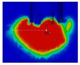
![Average Liquid Length [mm] 18 mm Mixture Fraction [-] 2d computational mesh Diesel Engines: spray modeling 11 Spray A from Engine Combustion Network Spray model setup](/docs-images/79/80025989/images/11-0.jpg "Injection: blob Breakup: KHRT Evaporation: Spalding CFD setup Turbulence model: standard k-e with modified C 1 Test conditions Fuel n-dodecane Nozzle diameter: 9 mm p")
 Experimental Computed 7 8 9 1 11 Ambient Temperature [K]")
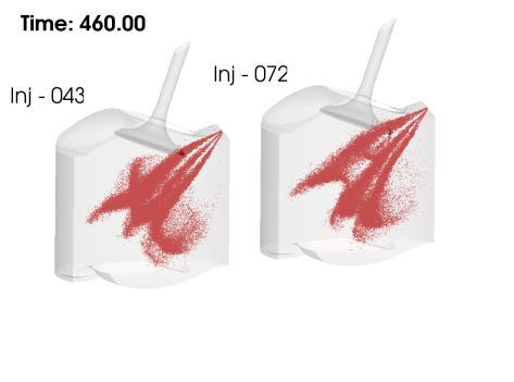
11 Average Liquid Length [mm] 18 mm Mixture Fraction [-] 2d computational mesh Diesel Engines: spray modeling 11 Spray A from Engine Combustion Network Spray model setup Injection: blob Breakup: KHRT Evaporation: Spalding CFD setup Turbulence model: standard k-e with modified C 1 Test conditions Fuel n-dodecane Nozzle diameter: 9 mm p inj : 5-15 MPa T amb : 7-12 K r amb : kg/m 3 Baseline (p inj = 15 MPa; T amb = 9 K; r amb = 22.8 kg/m 3 ) Dashed: exp Continuous: calc. Liquid Vapor z = 22.5 mm Exp PoliMI z = 45 mm Distance from axis [mm] Parametric variations (T amb, r amb ) Experimental Computed Ambient Temperature [K]
12 Diesel Engines: spray modeling 12 FPT C11 Spray (collaboration with TU/e DI N. Maes and Prof. B. Somers, FPT support) TU/e optical vessel 3D mesh (a) CFD Setup (b) Validation Liquid: exp vs computed extinction profiles Liquid penetration: DBI Vapor penetration: Schlieren Operating conditions Nozzle diameter:.25 mm Ambient temperature: 9 K ANR C1 C2 P inj [MPa] r amb [kg/m 3 ] Consistent with the engine grid in size and structure Spray Huh-Gosman atomization Pilch-Erdman breakup Turbulence modeling k-e with modified C 1
13 Diesel Engines: spray modeling 13 FPT C11 Spray (collaboration with TU/e DI N. Maes and Prof. B. Somers, FPT support) TU/e optical vessel 3D mesh (a) CFD Setup (b) Validation Liquid: exp vs computed extinction profiles Liquid penetration: DBI Vapor penetration: Schlieren Operating conditions Nozzle diameter:.25 mm Ambient temperature: 9 K ANR C1 C2 P inj [MPa] r amb [kg/m 3 ] Consistent with the engine grid in size and structure Spray Huh-Gosman atomization Pilch-Erdman breakup Turbulence modeling k-e with modified C 1
 TU/e optical vessel 3D mesh (a) CFD Setup (b) Validation Liquid: exp vs computed extinction profiles Liquid penetration: DBI")
![Vapor penetration: Schlieren Operating conditions Nozzle diameter:.25 mm Ambient temperature: 9 K ANR C1 C2 P inj [MPa] 15 8 15 r amb [kg/m 3 ] 22.](/docs-images/79/80025989/images/14-8.jpg "8 4 4 Consistent with the engine grid in size and structure Spray Huh-Gosman atomization Pilch-Erdman breakup Turbulence modeling k-e with modified C")
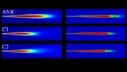
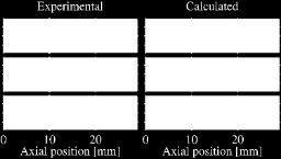
14 Diesel Engines: spray modeling 14 FPT C11 Spray (collaboration with TU/e DI N. Maes and Prof. B. Somers, FPT support) TU/e optical vessel 3D mesh (a) CFD Setup (b) Validation Liquid: exp vs computed extinction profiles Liquid penetration: DBI Vapor penetration: Schlieren Operating conditions Nozzle diameter:.25 mm Ambient temperature: 9 K ANR C1 C2 P inj [MPa] r amb [kg/m 3 ] Consistent with the engine grid in size and structure Spray Huh-Gosman atomization Pilch-Erdman breakup Turbulence modeling k-e with modified C 1 Vapor: exp (Schlieren), calc. (mixture fraction threshold)
 Mesh generation CFD")


 or snappyhexmesh (OpenFOAM) This work")
15 Diesel Engines: cold flow 15 Steady state flow bench simulations (FPT Industrial, Gilles Hardy) Mesh generation CFD Setup Steady-state flow Turbulence model: standard k-e Porous media acts as a flow straigthner in the computational mesh: computation of the swirl torque Verification of angular momentum conservation across the mesh boundaries. Cartesian, body fitted grids with boundary layer generated with cartesianmesh (cfmesh) or snappyhexmesh (OpenFOAM) This work was part of Davide Paredi MSc Thesis
 Computed")


16 Diesel Engines: cold flow Steady state flow bench simulations (FPT Industrial, Gilles Hardy) Computed flow field Lift = 5 mm Flow coeff. C.8 d [-] Lift = 1 mm Exp. Calc Swirl number N s [-] from Torque Lift = 5 mm Lift = 1 mm Exp. Calc. This work was part of Davide Paredi MSc Thesis
17 Diesel Engines 17 Combustion modeling Characteristic time-scale model (CTC) Well-mixed model Medium-duty engine operating at low-load with iso-octane fuel. Passenger-car Diesel engine mrif model N-dodecane spray combustion at constant volume conditions ECN Spray-A experiment Variation of ambient temperature, density, oxygen and injection pressure Kinetic mechanism: Luo et al. (111 species, 467 reactions) Ignition delay Density Inj. Press. O 2 conc. Amb. Temp Computed Experimental
18 Diesel Engines 18 Combustion modeling Characteristic time-scale model (CTC) Well-mixed model Medium-duty engine operating at low-load with iso-octane fuel. Passenger-car Diesel engine mrif model N-dodecane spray combustion at constant volume conditions ECN Spray-A experiment Variation of ambient temperature, density, oxygen and injection pressure Kinetic mechanism: Luo et al. (111 species, 467 reactions) Flame lift-off Density Inj. Press. O 2 conc. Amb. Temp Computed Experimental


19 Diesel Engines: validation 19 Spray B in Engines (from ECN, collaboration with Dr. Eagle, Dr. Malbec, Dr. Musculus) Optically accessible engine with three hole injector CFD setup and tested points Validation: non reacting Liquid length Vapor distribution CALC. CALC. Nozzle design very similar to spray A: possibility to perform same studies in engine and constantvolume vessel. This work is part of Amin Maghbouli PhD project Same CFD setup used in Spray A simulations, two different combustion models tested: mrif and well-mixed. Tested conditions T@SOI: 8-1 K P inj [bar]: 5 15 bar O 2 [%]: % SOI: kg/m 3 Fuel: n-dodecane EXP EXP
 Optically accessible engine with three hole injector CFD setup and tested points Validation: reacting Nozzle design very similar to spray A: possibility to perform same studies in engine")
20 Diesel Engines: validation 2 Spray B in Engines (from ECN, collaboration with Dr. Eagle, Dr. Malbec, Dr. Musculus) Optically accessible engine with three hole injector CFD setup and tested points Validation: reacting Nozzle design very similar to spray A: possibility to perform same studies in engine and constantvolume vessel. This work is part of Amin Maghbouli PhD project Automatically generated grid Same CFD setup used in Spray A simulations, two different combustion models tested: mrif and well-mixed. Tested conditions T@SOI: 8-1 K P inj [bar]: 5 15 bar O 2 [%]: % SOI: kg/m 3 Fuel: n-dodecane
21 Diesel Engines: validation 21 EU 6 FPT Engine MD (support from FPT, DI Gilles Hardy) Cylinder pressure validation (mrif and well-mixed) 75% load, 15% EGR, 2 injections 4 14 Exp. m-rif Exp. 4 Grid automatically generated Crank Angle [deg] Initial conditions from 1D simulations 5 Well-mixed 35 7 Pressure [bar] 3 m-rif [rpm] 4 9 Well-mixed 12 Pressure [bar] 8 25% load, 2% EGR, 3 injections Heat release rate [J/kg] bmep/bmepmax Crank Angle [deg] 5 Heat release rate [J/kg] Five operating points: with different EGR levels
22 Diesel Engines: validation 22 EU 6 FPT Engine MD (support from FPT, DI Gilles Hardy) Cylinder pressure validation (mrif and well-mixed) 1% load, 35% EGR, 3 injections 4 7 Exp. m-rif Exp. 3 4 Grid automatically generated Crank Angle [deg] Initial conditions from 1D simulations 5 Pressure [bar] 35 5 [rpm] 4 16 Well-mixed 6 Pressure [bar] 8 Full load, % EGR, 1 injection Heat release rate [J/kg] bmep/bmepmax 1 m-rif Well-mixed Crank Angle [deg] 5 Heat release rate [J/kg] Five operating points: with different EGR levels
23 Cyl. Pressure [bar] Heat Release Rate [J/deg] Diesel Engines: validation 23 PCCI engine (support from FPT, DI Gilles Hardy) PCCI combustion conditions Combustion model: Well-mixed High EGR rate (5%) 3 rpm Exp Exp. Computational mesh generated automatically with the Polimi tool Well-mixed Well-mixed Crank Angle [deg] Crank Angle [deg] Diesel fuel: n-dodecane Kinetic mechanism: Faravelli et al. (11 species, 3 reactions)

24 PCCI combustion conditions High EGR rate (5%) 3 rpm Computational mesh generated automatically with the Polimi tool Diesel Engines: validation 24 PCCI engine (support from FPT, DI Gilles Hardy)
 Automatic mesh generation Operating conditions SOI variation Soot/NO x trade-off Dual-fuel combustion Diesel: mrif Dual-fuel: PaSR NOx: Zeldovich, soot: Moss P cyl /P max Conventional")
25 NOx (normalized) soot (normalized) Diesel Engines: validation 25 Heavy Duty engines (support from GE Global Research, Dr. Pasunurthi) Automatic mesh generation Operating conditions SOI variation Soot/NO x trade-off Dual-fuel combustion Diesel: mrif Dual-fuel: PaSR NOx: Zeldovich, soot: Moss P cyl /P max Conventional Diesel Combustion Engine 1: SOI variation SOI #1, Exp. SOI #1, Calc. SOI #2, Exp. SOI #2, Calc. SOI #3, Exp. SOI #3, Calc Crank Angle [deg] p/p max Engine 2: pollutant prediction OP Crank Angle [deg] Exp. Calc. p/p max OP.3 Calc. Exp. OP.1 OP.2 OP Crank Angle [deg] Exp. Calc.
 Setup Reduced mechanism for Diesel (C 7 H 16 ) and natural gas Combustion model: PaSR Dual-fuel combustion RoHR/RoHR max OP 1 Validation Exp. Calc.")
26 Diesel Engines validation 26 Heavy Duty engines (support from GE Global Research, Dr. Pasunurthi) Setup Reduced mechanism for Diesel (C 7 H 16 ) and natural gas Combustion model: PaSR Dual-fuel combustion RoHR/RoHR max OP 1 Validation Exp. Calc. RoHR/RoHR max OP 2 Exp. Calc. Pollutants NO x : Zeldovich Soot: Moss Two operating points: same air/fuel ratio, different amount of injected Diesel fuel Crank Angle [deg] Crank Angle [deg] 1.2 Exp. 1 Calc..8 NO x / NO x,max OP 1 OP 2
 Spray C & Spray D These two")


 1.92 1.7 Experiments 1.")


27 Internal nozzle flow modeling (RANS, cavitation) Spray C & Spray D These two single hole injectors are defined by ECN to compare the effect of geometry on flow behavior. Spray C Spray D Spray C Diesel Engines 27 Next steps ECN contributors spray results C mdot (g/s) spray D mdot (g/s) Experiments 1.51 POLIMI Presssure across the hole axis and more mrif with multiple injections Tabulated kinetics: Homogeneous reactors Unsteady RIF blockmesh grid Spray C k factor=, sharp edge Spray D k factor=1.5, rounded edge Spray C cavitated Spray D Not cavitated Transported PDF combustion modeling: Eulerian Stochastic fields with tabulated kinetics! This work is part of Ehsan Tahmasebi PhD project

28 SI Engines
29 SI Engines 29 Methodology / model development Engine CAD data Nozzle flow Combustion models Automatic mesh generation Mesh handling Cold flow Spray models


 1 2 3 Velocity")


30 SI Engines: cold flow 3 Darmstadt optical engine (collaboration with Dr. B. Bohm and DI C. P. Ding) Velocity Magnitude (m/s) Four-valve engine, fully optically accessible PIV measurement techniques: low repetition rate planar PIV high-speed PIV (HS-PIV) stereoscopic PIV (SPIV) tomographic PIV (TPIV).
31 Lift [mm] SI Engines: cold flow 31 Full cycle SI: Darmstadt optical engine automatic mesh generation STL + data Geometry-oriented block structured mesh snappyhexmesh Exhaust Intake Crank Angle [deg] Bore 8 mm Stroke 6 mm Conrod 16 mm The user provides combustion chamber geometry and data (bore, stroke, valve lifts) A python program automatically recognizes the direction of ducts, cylinder and valves and generates a geometryoriented background grid snappyhexmesh is then run using the geometry-oriented background mesh
![Lift [mm] SI Engines: cold flow 32 Full cycle SI: Darmstadt optical](/docs-images/79/80025989/images/32-3.jpg "engine automatic mesh generation STL + data Geometry-oriented block")

 A python program automatically recognizes the")

32 Lift [mm] SI Engines: cold flow 32 Full cycle SI: Darmstadt optical engine automatic mesh generation STL + data Geometry-oriented block structured mesh snappyhexmesh Exhaust Intake Crank Angle [deg] Bore 8 mm Stroke 6 mm Conrod 16 mm The user provides combustion chamber geometry and data (bore, stroke, valve lifts) A python program automatically recognizes the direction of ducts, cylinder and valves and generates a geometryoriented background grid snappyhexmesh is then run using the geometry-oriented background mesh


33 SI Engines: cold flow 33 Full cycle SI: Darmstadt optical engine mesh management Full-cycle simulations: - Multiple meshes - Mesh to mesh interpolation strategy. Duration of each mesh: - User defined + quality criteria Initial mesh at Crank angle q q = q curr Generate a new mesh with snappyhexmesh q curr = q Move mesh for Dq Mesh quality and duration satisfied? NO q curr = q curr + Dq YES Move surface geometry to current crank angle q curr NO YES q curr = q end? End of meshing
34 SI Engines: cold flow 34 Full cycle SI: Darmstadt optical engine case setup Models and boundary conditions Engine geometry data Bore Stroke 86 mm 86 mm Compression ratio 8.5 IVO IVC EVO EVC Speed Combustion 325 CAD 485 CAD 15 CAD 345 CAD 85 rpm no Boundary conditions Unsteady boundary conditions (from exp. data) imposed at inlet and outlet ports. CFD models Second-order discretization (TVD) Turbulence model: standard k-e

 Cartesian mesh (automatically generated + snappyhexmesh) b) Flow-oriented mesh (automatically generated + Polimi")
35 SI Engines: cold flow 35 Full cycle SI: Darmstadt optical engine case setup Computational mesh Mesh layouts 4 mm mesh size in the ducts region; 2 mm mesh size in the cylinder and valve region; local refinement up to 1 mm close to cylinder head, piston and liner boundaries; local refinement up to.25 mm close to the valves boundaries. a) Cartesian mesh (automatically generated + snappyhexmesh) b) Flow-oriented mesh (automatically generated + Polimi tool + snappyhexmesh)

36 SI Engines: cold flow 36 Full cycle SI: Darmstadt optical engine validation
37 U y [m/s] SI Engines: cold flow 37 Full cycle SI: Darmstadt optical engine validation x and y velocity components along four different measurement lines located at different distances from the cylinder head. 45 CAD mid-intake Similar behavior between the two grids, flow dominated by the incoming air jet Experimental Cartesian Flow-oriented Y = mm Y = -1 mm Y = -2 mm Y = -3 mm -1 y -2-3 x Flow-oriented Cartesian Experimental
38 U x [m/s] SI Engines: cold flow 38 Full cycle SI: Darmstadt optical engine validation x and y velocity components along four different measurement lines located at different distances from the cylinder head. 45 CAD mid-intake Similar behavior between the two grids, flow dominated by the incoming air jet Experimental Cartesian Flow-oriented Y = mm Y = -1 mm Y = -2 mm Y = -3 mm -1 y -2-3 x Flow-oriented Cartesian Experimental
39 U y [m/s] SI Engines: cold flow 39 Full cycle SI: Darmstadt optical engine validation x and y velocity components along four different measurement lines located at different distances from the cylinder head. 54 CAD BDC, intake Better prediction of the flow oriented grid: Vortex location, distribution of the two main streams Experimental Cartesian Flow-oriented Y = mm Y = -1 mm Y = -2 mm Y = -3 mm -1 y -2-3 x Flow-oriented Cartesian Experimental
![U x [m/s] SI Engines: cold flow 4 Full cycle SI: Darmstadt optical engine validation x and y velocity components along four different measurement lines located at different distances from the](/docs-images/79/80025989/images/40-1.jpg "cylinder head.")
40 U x [m/s] SI Engines: cold flow 4 Full cycle SI: Darmstadt optical engine validation x and y velocity components along four different measurement lines located at different distances from the cylinder head. 54 CAD BDC, intake Better prediction of the flow oriented grid: Vortex location, distribution of the two main streams Experimental Cartesian Flow-oriented Y = mm Y = -1 mm Y = -2 mm Y = -3 mm -1 y -2-3 x Flow-oriented Cartesian Experimental
![U y [m/s] SI Engines: cold flow 41 Full cycle SI: Darmstadt optical engine validation x and y velocity components along four different measurement lines located at different distances from the](/docs-images/79/80025989/images/41-2.jpg "cylinder head.")
41 U y [m/s] SI Engines: cold flow 41 Full cycle SI: Darmstadt optical engine validation x and y velocity components along four different measurement lines located at different distances from the cylinder head. 66 CAD mid-compression Flow-oriented grid better describe the tumble vortex structure Experimental Cartesian Flow-oriented Y = mm Y = -1 mm Y = -2 mm Y = -3 mm -1 y -2-3 x Flow-oriented Cartesian Experimental
42 U x [m/s] SI Engines: cold flow 42 Full cycle SI: Darmstadt optical engine validation x and y velocity components along four different measurement lines located at different distances from the cylinder head. 66 CAD mid-compression Flow-oriented grid better describe the tumble vortex structure Experimental Cartesian Flow-oriented Y = mm Y = -1 mm Y = -2 mm Y = -3 mm -1 y -2-3 x Flow-oriented Cartesian Experimental

![Montanaro) Optically accessible GDI engine Injection pressure [bar]](/docs-images/79/80025989/images/43-1.jpg "Operating points SOI [ BTDC] Charge stratification 1 1 6 High 2 1 11 Low 3 6")
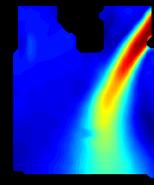
43 SI Engines: GDI fuel-air mixing 43 Stratified engine (collaboration with IM-CNR, Ing. Sementa, Ing. Montanaro) Optically accessible GDI engine Injection pressure [bar] Operating points SOI [ BTDC] Charge stratification High Low High Low bmep = 7.2 bar, SA = 13 BTDC; l = 1.15 (lean)


44 SI Engines: GDI fuel-air mixing 44 Stratified engine Optically accessible GDI engine: optical/computed data correlation Fuel m.f. P inj = 1 bar; SOI = 11 BTDC Soot chemiluminescence P inj.12 = 1 bar; SOI = 11 BTDC Fuel m.f. P inj = 6 bar; SOI = 6 BTDC Soot chemiluminescence P inj.12 = 6 bar; SOI = 7 BTDC Possible sources of soot: Rich pockets Wall-film Correlated with optical soot chemiluminescence Wall-film l distribution Wall-film l distribution

 Coherent flamelet model for flame propagation in the")


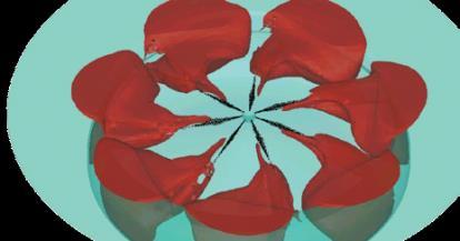
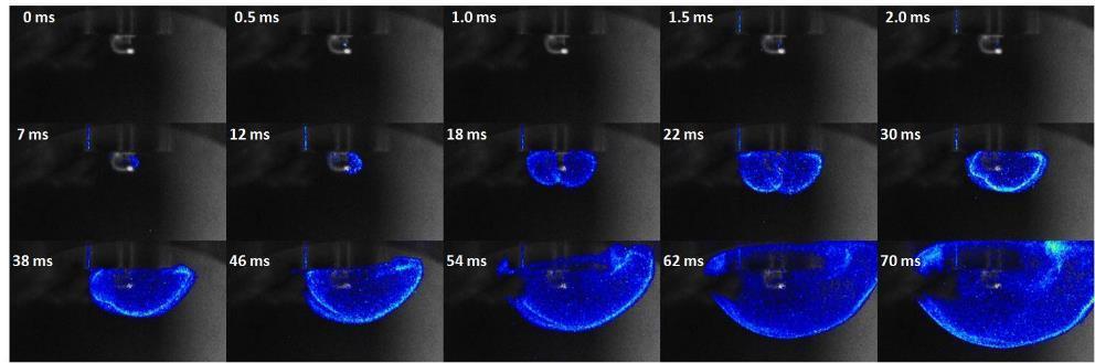
45 SI Engines: combustion 45 Modeling Comprehensive combustion model Detailed description of the flame kernel growth process via Lagrangian approach and suitable sub-models (breakdown, electrical circuit, wrinking) Coherent flamelet model for flame propagation in the Eulerian phase (gas) Strict coupling between Eulerian and Lagrangian phases Sub-models Secondary circuit energy transfer R p R s L p L s Spark gap hq el r i Breakdown T i (>1 K) T u (3-6 K) Flame surface density spk N f i 1 i S i V cell Lagrangian particles for the spark-channel Mass and energy equations solved for the flame kernel particles Particles convected by the flow, possibility to predict restrike Possibility to predict the effects of local flow, mixture conditions, turbulence, electrical circuit properties (voltage, current). Prediction of misfire also possible.


 This work is part of")
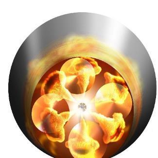
46 SI Engines: combustion 46 Assessment and validation Applications Results Pressurized vessels Multi-ignition systems Fan-generated flow velocity and turbulence fields at the spark-gap Initial combustion stage (Lagrangian Eulerian coupling) Fully turbulent flame (Eulerian model only) This work is part of Lorenzo Sforza PhD project
![Enflammed volume [cm 3 ] Enflammed volume [cm 3 ] SI Engines:](/docs-images/79/80025989/images/47-0.jpg "combustion 47 Experimental validation: Herweg and Maly Engine Flow")


47 Enflammed volume [cm 3 ] Enflammed volume [cm 3 ] SI Engines: combustion 47 Experimental validation: Herweg and Maly Engine Flow field, flame propagation and plasma temperature details Calc., 1 rpm, l = 1. Calc., 1 rpm, l = 1. Exp., 1 rpm, l = 1. Exp., 1 rpm, l = Calc., 1 rpm, l = 1. Calc., 3 rpm, l = 1. Calc., 125 rpm, l = 1. Exp., 1 rpm, l = 1. Exp., 3 rpm, l = 1. Exp., 125 rpm, l = 1..8 Peripheral Central Time after spark [ms] This work is part of Lorenzo Sforza PhD project Time after spark [ms]


48 Conclusions 48 CFD modeling of in-cylinder phenomena at Polimi with OpenFOAM Detailed models continuously validated and improved: Fundamental studies Applied research Consolidated methodologies, currently applied in the context of industrial collaborations but there is still a lot to do!
49 Thanks for your attention!
Gas exchange and fuel-air mixing simulations in a turbocharged gasoline engine with high compression ratio and VVA system
 Third Two-Day Meeting on Internal Combustion Engine Simulations Using the OpenFOAM technology, Milan 22 nd -23 rd February 2018. Gas exchange and fuel-air mixing simulations in a turbocharged gasoline
Incorporation of Flamelet Generated Manifold Combustion Closure to OpenFOAM and Lib-ICE
 Multiphase and Reactive Flows Group 3 rd Two-day Meeting on IC Engine Simulations Using OpenFOAM Technology 22-23 Feb 2018 - Milano Incorporation of Flamelet Generated Manifold Combustion Closure to OpenFOAM
Lib-ICE A C++ object-oriented library for internal combustion engine simulations: spray and combustion modeling
 5 th OpenFOAM Workshop, Goteborg, 21-24 June 2010 Lib-ICE A C++ object-oriented library for internal combustion engine simulations: spray and combustion modeling T. Lucchini, G. D Errico, D. Ettorre, E.
In-cylinder flow and combustion modeling using the OpenFOAM technology
 Workshop "HPC enabling of OpenFOAM for CFD applications" In-cylinder flow and combustion modeling using the OpenFOAM technology T. Lucchini, G. Montenegro, G. D Errico, A. Onorati, L. Cornolti Department
Recent Advances in DI-Diesel Combustion Modeling in AVL FIRE A Validation Study
 International Multidimensional Engine Modeling User s Group Meeting at the SAE Congress April 15, 2007 Detroit, MI Recent Advances in DI-Diesel Combustion Modeling in AVL FIRE A Validation Study R. Tatschl,
Numerical Investigation of the Influence of different Valve Seat Geometries on the In-Cylinder Flow and Combustion in Spark Ignition Engines
 Institute for Combustion and Gas Dynamics Fluid Dynamics Numerical Investigation of the Influence of different Valve Seat Geometries on the In-Cylinder Flow and Combustion in Spark Ignition Engines Peter
Marc ZELLAT, Driss ABOURI, Thierry CONTE and Riyad HECHAICHI CD-adapco
 16 th International Multidimensional Engine User s Meeting at the SAE Congress 2006,April,06,2006 Detroit, MI RECENT ADVANCES IN SI ENGINE MODELING: A NEW MODEL FOR SPARK AND KNOCK USING A DETAILED CHEMISTRY
LES of Spray Combustion using Flamelet Generated Manifolds
 LES of Spray Combustion using Flamelet Generated Manifolds Armin Wehrfritz, Ville Vuorinen, Ossi Kaario and Martti Larmi armin.wehrfritz@aalto.fi Aalto University Thermodynamics and Combustion technology
Modeling Constant Volume Chamber Combustion at Diesel Engine Condition
 Modeling Constant Volume Chamber Combustion at Diesel Engine Condition Z. Hu, R.Cracknell*, L.M.T. Somers Combustion Technology Department of Mechanical Engineering Eindhoven University of Technology *Shell
EFFECT OF INJECTION ORIENTATION ON EXHAUST EMISSIONS IN A DI DIESEL ENGINE: THROUGH CFD SIMULATION
 EFFECT OF INJECTION ORIENTATION ON EXHAUST EMISSIONS IN A DI DIESEL ENGINE: THROUGH CFD SIMULATION *P. Manoj Kumar 1, V. Pandurangadu 2, V.V. Pratibha Bharathi 3 and V.V. Naga Deepthi 4 1 Department of
Validation and Verification of ANSYS Internal Combustion Engine Software. Martin Kuntz, ANSYS, Inc.
 Validation and Verification of ANSYS Internal Combustion Engine Software Martin Kuntz, ANSYS, Inc. Contents Definitions Internal Combustion Engines Demonstration example Validation & verification Spray
Marc ZELLAT, Driss ABOURI and Stefano DURANTI CD-adapco
 17 th International Multidimensional Engine User s Meeting at the SAE Congress 2007,April,15,2007 Detroit, MI RECENT ADVANCES IN DIESEL COMBUSTION MODELING: THE ECFM- CLEH COMBUSTION MODEL: A NEW CAPABILITY
System Simulation for Aftertreatment. LES for Engines
 System Simulation for Aftertreatment LES for Engines Christopher Rutland Engine Research Center University of Wisconsin-Madison Acknowledgements General Motors Research & Development Caterpillar, Inc.
Numerical Study on the Combustion and Emission Characteristics of Different Biodiesel Fuel Feedstocks and Blends Using OpenFOAM
 Numerical Study on the Combustion and Emission Characteristics of Different Biodiesel Fuel Feedstocks and Blends Using OpenFOAM Harun M. Ismail 1, Xinwei Cheng 1, Hoon Kiat Ng 1, Suyin Gan 1 and Tommaso
CFD Combustion Models for IC Engines. Rolf D. Reitz
 CFD Combustion Models for IC Engines Rolf D. Reitz Engine Research Center University of Wisconsin-Madison ERC Symposium, June 7, 27 http://www.cae.wisc.edu/~reitz Combustion and Emission Models at the
OPTICAL ANALYSIS OF A GDI SPRAY WALL-IMPINGEMENT FOR S.I. ENGINES. Istituto Motori CNR, Napoli Italy
 OPTICAL ANALYSIS OF A GDI SPRAY WALL-IMPINGEMENT FOR S.I. ENGINES A. Montanaro, L. Allocca, S. Alfuso Istituto Motori CNR, Napoli Italy XV National Meeting, Milano 29-30 Novembre 2007 GENERAL CONSIDERATIONS
Combustion PVM-MF. The PVM-MF model has been enhanced particularly for dualfuel
 Contents Extensive new capabilities available in STAR-CD/es-ice v4.20 Combustion Models see Marc Zellat presentation Spray Models LES New Physics Developments in v4.22 Combustion Models PVM-MF Crank-angle
Modelling Combustion in DI-SI using the G-equation Method and Detailed Chemistry: Emissions and knock. M.Zellat, D.Abouri, Y.Liang, C.
 Modelling Combustion in DI-SI using the G-equation Method and Detailed Chemistry: Emissions and knock Realize innovation. M.Zellat, D.Abouri, Y.Liang, C.Kralj Main topics of the presentation 1. Context
Crankcase scavenging.
 Software for engine simulation and optimization www.diesel-rk.bmstu.ru The full cycle thermodynamic engine simulation software DIESEL-RK is designed for simulating and optimizing working processes of two-
Dual Fuel Engine Charge Motion & Combustion Study
 Dual Fuel Engine Charge Motion & Combustion Study STAR-Global-Conference March 06-08, 2017 Berlin Kamlesh Ghael, Prof. Dr. Sebastian Kaiser (IVG-RF), M. Sc. Felix Rosenthal (IFKM-KIT) Introduction: Operation
Recent enhancement to SI-ICE combustion models: Application to stratified combustion under large EGR rate and lean burn
 Recent enhancement to SI-ICE combustion models: Application to stratified combustion under large EGR rate and lean burn G. Desoutter, A. Desportes, J. Hira, D. Abouri, K.Oberhumer, M. Zellat* TOPICS Introduction
IC Engines Roadmap. STAR-CD/es-ice v4.18 and Beyond. Richard Johns
 IC Engines Roadmap STAR-CD/es-ice v4.18 and Beyond Richard Johns Strategy es-ice v4.18 2D Automated Template Meshing Spray-adapted Meshing Physics STAR-CD v4.18 Contents Sprays: ELSA Spray-Wall Impingement
Figure 1: The spray of a direct-injecting four-stroke diesel engine
 MIXTURE FORMATION AND COMBUSTION IN CI AND SI ENGINES 7.0 Mixture Formation in Diesel Engines Diesel engines can be operated both in the two-stroke and four-stroke process. Diesel engines that run at high
Overview & Perspectives for Internal Combustion Engine using STAR-CD. Marc ZELLAT
 Overview & Perspectives for Internal Combustion Engine using STAR-CD Marc ZELLAT TOPICS Quick overview of ECFM family models Examples of validation for Diesel and SI-GDI engines Introduction to multi-component
Assessment of Innovative Bowl Geometries over Different Swirl Ratios/EGR rates
 Assessment of Innovative Bowl Geometries over Different Swirl Ratios/EGR rates Andrea Bianco 1, Federico Millo 2, Andrea Piano 2, Francesco Sapio 2 1: POWERTECH Engineering S.r.l., Turin ITALY 2: Politecnico
PDF-based simulations of in-cylinder combustion in a compression-ignition engine
 Paper # 070IC-0192 Topic: Internal Combustion Engines 8 th US National Combustion Meeting Organized by the Western States Section of the Combustion Institute and hosted by the University of Utah May 19-22,
Marc ZELLAT, Driss ABOURI, Thierry CONTE. CD-adapco Group
 Advanced modeling of DI Diesel Engines: Investigations on Combustion, High EGR level and multipleinjection Application to DI Diesel Combustion Optimization Marc ZELLAT, Driss ABOURI, Thierry CONTE CD-adapco
Foundations of Thermodynamics and Chemistry. 1 Introduction Preface Model-Building Simulation... 5 References...
 Contents Part I Foundations of Thermodynamics and Chemistry 1 Introduction... 3 1.1 Preface.... 3 1.2 Model-Building... 3 1.3 Simulation... 5 References..... 8 2 Reciprocating Engines... 9 2.1 Energy Conversion...
In-Cylinder Engine Calculations: New Features and Upcoming Capabilities Richard Johns & Gerald Schmidt
 In-Cylinder Engine Calculations: New Features and Upcoming Capabilities Richard Johns & Gerald Schmidt Contents Brief Review of STAR-CD/es-ice v4.20 Combustion Models Spray Models LES New Physics Developments
Emissions predictions for Diesel engines based on chemistry tabulation
 Emissions predictions for Diesel engines based on chemistry tabulation C. Meijer, F.A. Tap AVL Dacolt BV (The Netherlands) M. Tvrdojevic, P. Priesching AVL List GmbH (Austria) 1. Introduction It is generally
A comprehensive methodology for computational fluid dynamics combustion modeling of industrial diesel engines
 Special Issue Article A comprehensive methodology for computational fluid dynamics combustion modeling of industrial diesel engines International J of Engine Research 2017, Vol. 18(1-2) 26 38 Ó IMechE
Effect of mesh structure in the KIVA-4 code with a less mesh dependent spray model for DI diesel engine simulations
 International Multidimensional Engine Modeling User's Group Meeting at the SAE Congress, April 19, 29, Detroit, MI Effect of mesh structure in the KIVA-4 code with a less mesh dependent spray model for
Rapid Meshing and Advanced Physical Modeling for Gasoline DI Engine Application
 Rapid Meshing and Advanced Physical Modeling for Gasoline DI Engine Application R. Tatschl, H. Riediger, Ch. v. Künsberg Sarre, N. Putz and F. Kickinger AVL LIST GmbH A-8020 Graz AUSTRIA Gasoline direct
Natural Gas fuel for Internal Combustion Engine
 Natural Gas fuel for Internal Combustion Engine L. Bartolucci, S. Cordiner, V. Mulone, V. Rocco University of Rome Tor Vergata Department of Industrial Engineering Outline Introduction Motivations and
Maximizing Engine Efficiency by Controlling Fuel Reactivity Using Conventional and Alternative Fuels. Sage Kokjohn
 Maximizing Engine Efficiency by Controlling Fuel Reactivity Using Conventional and Alternative Fuels Sage Kokjohn Acknowledgments Direct-injection Engine Research Consortium (DERC) US Department of Energy/Sandia
Improving Fuel Efficiency with Fuel-Reactivity-Controlled Combustion
 ERC Symposium 2009 1 Improving Fuel Efficiency with Fuel-Reactivity-Controlled Combustion Rolf D. Reitz, Reed Hanson, Derek Splitter, Sage Kokjohn Engine Research Center University of Wisconsin-Madison
Comparison of Velocity Vector Components in a Di Diesel Engine: Analysis through Cfd Simulation
 IOSR Journal of Mechanical and Civil Engineering (IOSR-JMCE) e-issn: 2278-1684,p-ISSN: 2320-334X PP. 55-60 www.iosrjournals.org Comparison of Velocity Vector Components in a Di Diesel Engine: Analysis
Simulation of gas exchange and combustion processes in SI and Diesel engines: current state of models and examples of applications
 Simulation of gas exchange and combustion processes in SI and Diesel engines: current state of models and examples of applications T. Lucchini, G. D Errico, D. Ettorre, M. Fiocco Department of Energy,
Simulation of the Mixture Preparation for an SI Engine using Multi-Component Fuels
 ICE Workshop, STAR Global Conference 2012 March 19-21 2012, Amsterdam Simulation of the Mixture Preparation for an SI Engine using Multi-Component Fuels Michael Heiss, Thomas Lauer Content Introduction
Control of PCCI Combustion using Physical and Chemical Characteristics of Mixed Fuel
 Doshisha Univ. - Energy Conversion Research Center International Seminar on Recent Trend of Fuel Research for Next-Generation Clean Engines December 5th, 27 Control of PCCI Combustion using Physical and
Investigation on Diesel Engine for Airflow and Combustion in a Hemispherical Combustion Chamber
 International Journal of Current Engineering and Technology E-ISSN 2277 4106, P-ISSN 2347 5161 2015INPRESSCO, All Rights Reserved Available at http://inpressco.com/category/ijcet Research Article Investigation
Effect of piston profile on performance and emission characteristics of a GDI engine with split injection strategy A CFD study
 IOP Conference Series: Materials Science and Engineering PAPER OPEN ACCESS Effect of piston profile on performance and emission characteristics of a GDI engine with split injection strategy A CFD study
ENGINE COMBUSTION SIMULATION USING OPENFOAM
 ENGINE COMBUSTION SIMULATION USING OPENFOAM K. S. Kolambe 1, S. L. Borse 2 1 Post Graduate Engineering Student, Department of Mechanical Engineering. 2, Associate Professor, Department of Mechanical Engineering
* Corresponding author
 Characterization of Dual-Fuel PCCI Combustion in a Light-Duty Engine S. L. Kokjohn * and R. D. Reitz Department of Mechanical Engineering University of Wisconsin - Madison Madison, WI 5376 USA Abstract.
Numerical Investigation of the Effect of Excess Air and Thermal Power Variation in a Liquid Fuelled Boiler
 Proceedings of the World Congress on Momentum, Heat and Mass Transfer (MHMT 16) Prague, Czech Republic April 4 5, 2016 Paper No. CSP 105 DOI: 10.11159/csp16.105 Numerical Investigation of the Effect of
INFLUENCE OF THE NUMBER OF NOZZLE HOLES ON THE UNBURNED FUEL IN DIESEL ENGINE
 INFLUENCE OF THE NUMBER OF NOZZLE HOLES ON THE UNBURNED FUEL IN DIESEL ENGINE 1. UNIVERSITY OF RUSE, 8, STUDENTSKA STR., 7017 RUSE, BULGARIA 1. Simeon ILIEV ABSTRACT: The objective of this paper is to
Numerical Simulation of the Effect of 3D Needle Movement on Cavitation and Spray Formation in a Diesel Injector
 Journal of Physics: Conference Series PAPER OPEN ACCESS Numerical Simulation of the Effect of 3D Needle Movement on Cavitation and Spray Formation in a Diesel Injector To cite this article: B Mandumpala
Optical methods for combustion research
 KCFP Södertälje May 8, 2008 Optical methods for combustion research Mattias Richter Associate Professor Division of Combustion, Sweden Tolvan Tolvansson, 2007 Johannes Lindén, Division of Combustion Chemiluminescence
Effects of Dilution Flow Balance and Double-wall Liner on NOx Emission in Aircraft Gas Turbine Engine Combustors
 Effects of Dilution Flow Balance and Double-wall Liner on NOx Emission in Aircraft Gas Turbine Engine Combustors 9 HIDEKI MORIAI *1 Environmental regulations on aircraft, including NOx emissions, have
EEN-E2002 Combustion Technology 2017 LE 3 answers
 EEN-E2002 Combustion Technology 2017 LE 3 answers 1. Plot the following graphs from LEO-1 engine with data (Excel_sheet_data) attached on my courses? (12 p.) a. Draw cyclic pressure curve. Also non-fired
APPLICATION OF LDA AND PIV TECHNIQUES TO THE VALIDATION OF VECTIS USING BOUNDARY MESH MOTION
 APPLICATION OF LDA AND PIV TECHNIQUES TO THE VALIDATION OF VECTIS USING BOUNDARY MESH MOTION S M Sapsford Ricardo Consulting Engineers Ltd. Computational fluid dynamics (CFD) is being increasingly used
Engine Heat Transfer. Engine Heat Transfer
 Engine Heat Transfer 1. Impact of heat transfer on engine operation 2. Heat transfer environment 3. Energy flow in an engine 4. Engine heat transfer Fundamentals Spark-ignition engine heat transfer Diesel
Model validation of the SI test engine
 TEKA. COMMISSION OF MOTORIZATION AND ENERGETICS IN AGRICULTURE 2013, Vol. 13, No. 2, 17 22 Model validation of the SI test engine Arkadiusz Jamrozik Institute of Thermal Machinery, Czestochowa University
HERCULES-2 Project. Deliverable: D8.8
 HERCULES-2 Project Fuel Flexible, Near Zero Emissions, Adaptive Performance Marine Engine Deliverable: D8.8 Study an alternative urea decomposition and mixer / SCR configuration and / or study in extended
NUMERICAL INVESTIGATION OF EFFECT OF EXHAUST GAS RECIRCULATION ON COMPRESSIONIGNITION ENGINE EMISSIONS
 ISSN (Online) : 2319-8753 ISSN (Print) : 2347-6710 International Journal of Innovative Research in Science, Engineering and Technology An ISO 3297: 2007 Certified Organization, Volume 2, Special Issue
Progress in Predicting Soot Particle Numbers in CFD Simulations of GDI and Diesel Engines
 International Multidimensional Engine Modeling User's Group Meeting April 20, 2015, Detroit, Michigan Progress in Predicting Soot Particle Numbers in CFD Simulations of GDI and Diesel Engines Abstract
Satbir Singh and Rolf D. Reitz Engine Research Center, Department of Mechanical Engineering, University of Wisconsin, Madison
 Comparison of Characteristic Time (), Representative Interactive Flamelet (RIF), and Direct Integration with Detailed Chemistry Combustion Models against Multi-Mode Combustion in a Heavy-Duty, DI Diesel
EXPERIMENTAL AND COMPUTATIONAL EVALUATION OF EMISSIONS OF AN ENGINE WITH A RE-ENTRANT PISTON BOWL - A VALIDATION
 International Journal of Mechanical Engineering and Technology (IJMET) Volume 8, Issue 6, June 2017, pp. 393 402, Article ID: IJMET_08_06_041 Available online at http://www.iaeme.com/ijmet/issues.asp?jtype=ijmet&vtype=8&itype=6
3D In-cylinder Cold Flow Simulation Studies in an IC Engine using CFD
 Volume 1, Issue 1, July-September, 2013, pp. 64-69, IASTER 2013 www.iaster.com, Online:2347-5188 Print: 2347-8772 ABSTRACT 3D In-cylinder Cold Flow Simulation Studies in an IC Engine using CFD A Lakshman,
International Multidimensional Engine Modeling User s Group Meeting April 7, 2014, Detroit, Michigan, USA
 International Multidimensional Engine Modeling User s Group Meeting April 7, 24, Detroit, Michigan, USA An extended CMC model for the simulation of diesel engines with multiple injections Michele Bolla,
COMBUSTION AND EXHAUST EMISSION IN COMPRESSION IGNITION ENGINES WITH DUAL- FUEL SYSTEM
 COMBUSTION AND EXHAUST EMISSION IN COMPRESSION IGNITION ENGINES WITH DUAL- FUEL SYSTEM WLADYSLAW MITIANIEC CRACOW UNIVERSITY OF TECHNOLOGY ENGINE-EXPO 2008 OPEN TECHNOLOGY FORUM STUTTGAT, 7 MAY 2008 APPLICATIONS
Univ.-Prof. Dr.-Ing. Heinz Pitsch Mathis Bode, Tobias Falkenstein, Jörn Hinrichs, Marco Davidovic, Liming Cai, Vincent Le Chenadec
 LES of Diesel Sprays Using Advanced Computational Methods and Models for Mixture and Emission Formation Univ.-Prof. Dr.-Ing. Heinz Pitsch Mathis Bode, Tobias Falkenstein, Jörn Hinrichs, Marco Davidovic,
Advanced Diesel Combustion Concept: PCCI - A Step Towards Meeting BS VI Emission Regulations
 October - November 2015 1. Advanced Diesel Combustion Concept: PCCI - A Step Towards Meeting BS VI Emission Regulations 2. ARAI offers Indigenously Developed Downsized 3 Cylinder High Power Density CRDI
Mechanical Engineering Design of a Split-Cycle Combustor. Experimental Fluid-Mechanics Research Group
 Mechanical Engineering Design of a Split-Cycle Combustor Dr Daniel D Coren Dr Nicolas D D Miché Experimental Fluid-Mechanics Research Group University of Brighton, March 2015 mechanical design considerations
2nd International Conference on Electronic & Mechanical Engineering and Information Technology (EMEIT-2012)
") The analysis of GDI engine soot emission based on spray and ignition timing tactics LIN Man-qun 1, 2, a, ZHOU Peng 1, 2, b, QIN Jing 1, 2, c, PEI Yi-qiang 2, d, PN Suo-zhu 2, e (1, Internal Combustion
The analysis of GDI engine soot emission based on spray and ignition timing tactics LIN Man-qun 1, 2, a, ZHOU Peng 1, 2, b, QIN Jing 1, 2, c, PEI Yi-qiang 2, d, PN Suo-zhu 2, e (1, Internal Combustion
Numerically Analysing the Effect of EGR on Emissions of DI Diesel Engine Having Toroidal Combustion Chamber Geometry
 Numerically Analysing the Effect of EGR on Emissions of DI Diesel Engine Having Toroidal Combustion Chamber Geometry Jibin Alex 1, Biju Cherian Abraham 2 1 Student, Dept. of Mechanical Engineering, M A
Module7:Advanced Combustion Systems and Alternative Powerplants Lecture 32:Stratified Charge Engines
 ADVANCED COMBUSTION SYSTEMS AND ALTERNATIVE POWERPLANTS The Lecture Contains: DIRECT INJECTION STRATIFIED CHARGE (DISC) ENGINES Historical Overview Potential Advantages of DISC Engines DISC Engine Combustion
Abstract 1. INTRODUCTION
 Abstract Study on Performance Characteristics of Scuderi Split Cycle Engine Sudeer Gowd Patil 1, Martin A.J. 2, Ananthesha 3 1- M.Sc. [Engg.] Student, 2-Asst. Professor, 3-Asst.Professor, Department of
Numerical Investigation in the Effect of Number of Nozzle Hole on Performance and Emission in Dual Fuel Engine
 Numerical Investigation in the Effect of Number of Nozzle Hole on Performance and Emission in Dual Fuel Engine B. Jafari *1, D.Domiri Ganji 2 1. Assistant Professor, 2. PhD Student, Babol University of
Simulating Gas-Air Mixture Formation for Dual-Fuel Applications
 Simulating Gas-Air Mixture Formation for Dual-Fuel Applications Karri Keskinen, Ossi Kaario, Mika Nuutinen, Ville Vuorinen, Zaira Künsch and Martti Larmi Thermodynamics and Combustion Technology Research
THE THEORETICAL STUDY ON INFLUENCE OF FUEL INJECTION PRESSURE ON COMBUSTION PARAMETERS OF THE MARINE 4-STROKE ENGINE
 Journal of KONES Powertrain and Transport, Vol. 23, No. 1 2016 THE THEORETICAL STUDY ON INFLUENCE OF FUEL INJECTION PRESSURE ON COMBUSTION PARAMETERS OF THE MARINE 4-STROKE ENGINE Jerzy Kowalski Gdynia
The Influence of Port Fuel Injection on Combustion Stability
 28..9 Technical The Influence of Port Fuel Injection on Combustion Stability Shoichi Kato, Takanori Hayashida, Minoru Iida Abstract The demands on internal combustion engines for low emissions and fuel
Evolution of Particle Size Distribution within the Engine Exhaust and Aftertreatment System
 Evolution of Particle Size Distribution within the Engine Exhaust and Aftertreatment System A. J. Smallbone (1, 2), D. Z. Y. Tay (2), W. L. Heng (2), S. Mosbach (2), A. York (2,3), M. Kraft (2) (1) cmcl
Introduction to combustion
 Introduction to combustion EEN-E005 Bioenergy 1 017 D.Sc (Tech) ssi Kaario Motivation Why learn about combustion? Most of the energy in the world, 70-80%, is produced from different kinds of combustion
Numerical Study of Flame Lift-off and Soot Formation in Diesel Fuel Jets
 Numerical Study of Flame Lift-off and Soot Formation in Diesel Fuel Jets Song-Charng Kong*, Yong Sun and Rolf D. Reitz Engine Research Center, Department of Mechanical Engineering University of Wisconsin
CFD Simulation of In-Cylinder Flow on Different Piston Bowl Geometries in a DI Diesel Engine
 Journal of Applied Fluid Mechanics, Vol. 9, No. 3, pp. 1147-1155, 2016. Available online at www.jafmonline.net, ISSN 1735-3572, EISSN 1735-3645. DOI: 10.18869/acadpub.jafm.68.228.24397 CFD Simulation of
Normal vs Abnormal Combustion in SI engine. SI Combustion. Turbulent Combustion
 Turbulent Combustion The motion of the charge in the engine cylinder is always turbulent, when it is reached by the flame front. The charge motion is usually composed by large vortexes, whose length scales
The Effect of Volume Ratio of Ethanol Directly Injected in a Gasoline Port Injection Spark Ignition Engine
 10 th ASPACC July 19 22, 2015 Beijing, China The Effect of Volume Ratio of Ethanol Directly Injected in a Gasoline Port Injection Spark Ignition Engine Yuhan Huang a,b, Guang Hong a, Ronghua Huang b. a
Lecture 5. Abnormal Combustion
 Lecture 5 Abnormal Combustion Abnormal Combustion The Abnormal Combustion:- When the combustion gets deviated from the normal behavior resulting loss of performance or damage to the engine. It is happened
CFD Simulation of Dry Low Nox Turbogas Combustion System
 CFD Simulation of Dry Low Nox Turbogas Combustion System L. Bucchieri - Engin Soft F. Turrini - Fiat Avio CFX Users Conference - Friedrichshafen June 1999 1 Objectives Develop a CFD model for turbogas
Towards a Universal Combustion Model in STAR-CD for IC Engines: From GDI to HCCI and Application to DI Diesel Combustion Optimization
 Towards a Universal Combustion Model in STAR-CD for IC Engines: From GDI to HCCI and Application to DI Diesel Combustion Optimization Marc ZELLAT*, Stefano DURANTI, YongJun LIANG, Cedomir KRALJ and Gerald
1. INTRODUCTION 2. EXPERIMENTAL INVESTIGATIONS
 HIGH PRESSURE HYDROGEN INJECTION SYSTEM FOR A LARGE BORE 4 STROKE DIESEL ENGINE: INVESTIGATION OF THE MIXTURE FORMATION WITH LASER-OPTICAL MEASUREMENT TECHNIQUES AND NUMERICAL SIMULATIONS Dipl.-Ing. F.
Investigation on PN Formation at GDI Engines at High Loads
 Investigation on PN Formation at GDI Engines at High Loads Denis Notheis (M.Sc.), Dr. Ing Markus Bertsch, Dr. Ing Amin Velji, Prof. Dr. sc. techn. Thomas Koch INSTITUT FÜR KOLBENMASCHINEN Injektor A KIT
is the crank angle between the initial spark and the time when about 10% of the charge is burned. θ θ
 ME 410 Day 30 Phases of Combustion 1. Ignition 2. Early flame development θd θ 3. Flame propagation b 4. Flame termination The flame development angle θd is the crank angle between the initial spark and
VECTIS CFD for Automotive application Ricardo tools to meet the demands
 VECTIS CFD for Automotive application Ricardo tools to meet the demands www.ricardo.com VECTIS Incylinder Analysis Introduction What is VECTIS Incylinder analysis process Validation Examples Introduction
Experimental investigation of ethanol-gasoline dual-fuel on particle emissions at the exhaust of a small displacement engine
 Experimental investigation of ethanol-gasoline dual-fuel on particle emissions at the exhaust of a small displacement engine F. Catapano, S. Di Iorio, P. Sementa, B. M. Vaglieco Istituto Motori CNR, Naples
Numerical Modelling of Mixture Formation and Combustion in DISI Hydrogen Engines with Various Injection Strategies
 Copyright 2014 SAE International 2014-01-2577 Numerical Modelling of Mixture Formation and Combustion in DISI Hydrogen Engines with Various Injection Strategies A. Hamzehloo and P.G. Aleiferis University
Flow Simulation of Diesel Engine for Prolate Combustion Chamber
 IJIRST National Conference on Recent Advancements in Mechanical Engineering (RAME 17) March 2017 Flow Simulation of Diesel Engine for Prolate Combustion Chamber R.Krishnakumar 1 P.Duraimurugan 2 M.Magudeswaran
POSIBILITIES TO IMPROVED HOMOGENEOUS CHARGE IN INTERNAL COMBUSTION ENGINES, USING C.F.D. PROGRAM
 POSIBILITIES TO IMPROVED HOMOGENEOUS CHARGE IN INTERNAL COMBUSTION ENGINES, USING C.F.D. PROGRAM Alexandru-Bogdan Muntean *, Anghel,Chiru, Ruxandra-Cristina (Dica) Stanescu, Cristian Soimaru Transilvania
Application of an Equilibrium Phase (EP) Spray Model to. Multi-component Gasoline Direct Injection
 Spray Model to. Multi-component Gasoline Direct Injection") Application of an Equilibrium Phase (EP) Spray Model to Multi-component Gasoline Direct Injection Zongyu Yue 1*, Rolf D. Reitz 2 1 Argonne National Laboratory, USA 2 University of Wisconsin-Madison, USA
Application of an Equilibrium Phase (EP) Spray Model to Multi-component Gasoline Direct Injection Zongyu Yue 1*, Rolf D. Reitz 2 1 Argonne National Laboratory, USA 2 University of Wisconsin-Madison, USA
8 th International Symposium TCDE Choongsik Bae and Sangwook Han. 9 May 2011 KAIST Engine Laboratory
 8 th International Symposium TCDE 2011 Choongsik Bae and Sangwook Han 9 May 2011 KAIST Engine Laboratory Contents 1. Background and Objective 2. Experimental Setup and Conditions 3. Results and Discussion
Cyclic Fluctuations of Charge Motion and Mixture Formation in a DISI Engine in Stratified Operation
 ABSTRACT Cyclic Fluctuations of Charge Motion and Mixture Formation in a DISI Engine in Stratified Operation The processes of an internal combustion engine are subject to cyclic fluctuations, which have
Comparison of Swirl, Turbulence Generating Devices in Compression ignition Engine
 Available online atwww.scholarsresearchlibrary.com Archives of Applied Science Research, 2016, 8 (7):31-40 (http://scholarsresearchlibrary.com/archive.html) ISSN 0975-508X CODEN (USA) AASRC9 Comparison
DARS FUEL MODEL DEVELOPMENT
 DARS FUEL MODEL DEVELOPMENT DARS Products (names valid since October 2012) DARS 0D & 1D tools Old name: DARS Basic DARS Reactive Flow Models tools for 3D/ CFD calculations DARS Fuel New! Advanced fuel
STUDY OF NOZZLE INJECTOR PERFORMANCE USING CFD
 STUDY OF NOZZLE INJECTOR PERFORMANCE USING CFD Vimal Kumar Pathak 1 and Sumit Gupta 2 1,2 Department of Mechanical Engineering, MNIT, Jaipur ABSTRACT The aim of this paper is to study the performance of
Development, Implementation, and Validation of a Fuel Impingement Model for Direct Injected Fuels with High Enthalpy of Vaporization
 Development, Implementation, and Validation of a Fuel Impingement Model for Direct Injected Fuels with High Enthalpy of Vaporization (SAE Paper- 2009-01-0306) Craig D. Marriott PE, Matthew A. Wiles PE,
CFD Modeling of Spray Formation in Diesel Engines
 Athens Journal of Technology and Engineering December 2017 CFD Modeling of Spray Formation in Diesel Engines By Mohamed Maher Ahmed Abu-Elhamyel Omar Hassan Alaa El-Din Ramadan Aya Diab Mostafa Abdelkhalek
COMPUTATIONAL MODELING OF DIESEL AND DUAL FUEL COMBUSTION USING CONVERGE CFD SOFTWARE
 COMPUTATIONAL MODELING OF DIESEL AND DUAL FUEL COMBUSTION USING CONVERGE CFD SOFTWARE Wan Nurdiyana Wan Mansor 1 and Daniel B. Olsen 2 1 School of Ocean Engineering, Universiti Malaysia Terengganu, Malaysia
The Effects of Chamber Temperature and Pressure on a GDI Spray Characteristics in a Constant Volume Chamber
 한국동력기계공학회지제18권제6호 pp. 186-192 2014년 12월 (ISSN 1226-7813) Journal of the Korean Society for Power System Engineering http://dx.doi.org/10.9726/kspse.2014.18.6.186 Vol. 18, No. 6, pp. 186-192, December 2014
PPC FOR LOW LOAD CONDITIONS IN MARINE ENGINE USING COMPUTATIONAL AND EXPERIMENTAL TECHNIQUES
 PPC FOR LOW LOAD CONDITIONS IN MARINE ENGINE USING COMPUTATIONAL AND EXPERIMENTAL TECHNIQUES Presented By:Kendra Shrestha Authors: K.Shrestha, O.Kaario, M. Imperato, T. Sarjovaara, M. Larmi Internal Combusion