WF3132 User s Manual. AC rev D
|
|
|
- Georgina Berry
- 6 years ago
- Views:
Transcription


1 AC rev D WireFlow AB, December 2012
2 Contents Support information... 2 Technical support and Product information... 2 WireFlow headquarters... 2 Important information... 2 Copyright... 2 High risk activities... 2 Device information... 3 Features... 3 Specifications... 3 Connection diagrams... 4 Software... 6 Requirements... 6 Installation... 6 Supported Platforms... 6 Required External wiring... 6 Usage... 7 Four banks of 1 x 8 (1wire) x 32 (1 wire) x 16 (2 wire) x 8 (4 wire) x 8 Matrix (1 wire)... 8 Troubleshooting... 9 FPGA utilization... 9 Installation... 9 Technical support and Professional services... 9 WireFlow AB 2012 AC rev D 1
3 Support information Technical support and Product information WireFlow headquarters WireFlow AB Theres Svenssons gata 10 SE Göteborg Sweden Please see appendix Technical support and Services for more information. WireFlow AB 2012 Important information Copyright The WF3132 module and accompanying software driver is Copyright 2012, WireFlow AB. High risk activities The software and hardware is not designed, manufactured or intended for use or resale as online control equipment in hazardous environments requiring fail-safe performance, such as in (but not limited to) the operation of nuclear facilities, aircraft navigation or communication systems, air traffic control, direct life support machines, or weapons systems, in which the failure of the Software could lead directly to death, personal injury, or severe physical or environmental damage ("High Risk Activities"). WireFlow and its suppliers specifically disclaim any express or implied warranty of fitness for High Risk Activities. WireFlow AB 2012 AC rev D 2
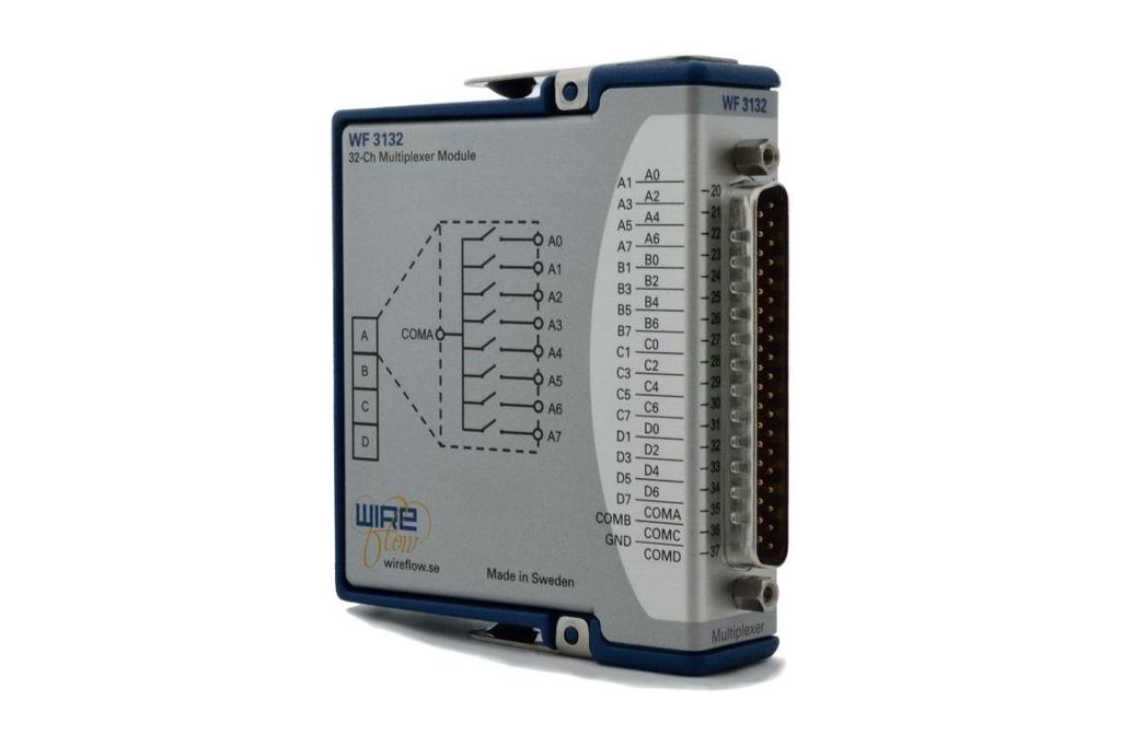
4 Device information Features 32 SPST relays Multiple configurations possible o 1 x 32 (1 wire) o 1 x 16 (2 wire) o 1 x 8 (4 wire) o Four banks of 1 x 8 (1wire) o 4 x 8 Matrix (1 wire) Standard 37-pin Dsub connector LabVIEW driver included Compatible with NI Veristand Specifications Number of Relays 32 Max Voltage Max Current 0.5A Max Power 60VDC/30VRMS 10W Max Resistance 0.3Ω Update Rate 200S/s WireFlow AB 2012 AC rev D 3
5 Connection diagrams COM A COM B COM C COM D A0 A1 A2 A3 A4 A5 A6 A7 B0 B1 B2 B3 B4 B5 B6 B7 C0 C1 C2 C3 C4 C5 C6 C7 D0 D1 D2 D3 D4 D5 D6 D7 Figure 1: Four banks of 1 x 8 (1 x 8, 4 wire) COM A COM C A0 A1 A2 A3 A4 A5 A6 A7 B0 B1 B2 B3 B4 B5 B6 B7 C0 C1 C2 C3 C4 C5 C6 C7 D0 D1 D2 D3 D4 D5 D6 D7 Figure 2: 1 x 16 (2 wire) WireFlow AB 2012 AC rev D 4
6 A0 A1 A2 A3 A4 A5 A6 A7 WireFlow AB COM A A0 A1 A2 A3 A4 A5 A6 A7 B0 B1 B2 B3 B4 B5 B6 B7 C0 C1 C2 C3 C4 C5 C6 C7 D0 D1 D2 D3 D4 D5 D6 D7 Figure 3: 1 x 32 (1 wire) COM A COM B COM C COM D Figure 4: 4 x 8 Matrix (1 wire) WireFlow AB 2012 AC rev D 5
7 Software The WF3144 is delivered with a LabVIEW driver to manage the module using FPGA property nodes and IO nodes. This chapter describes the installation, requirements and basic usage. Requirements LabVIEW Full (version >= 2011) LabVIEW FPGA module NI RIO (version >= 4.1) VI Package Manager (for installation) The WF3132 driver currently requires the LabVIEW FPGA toolkit. The software for the WF-3132 is delivered as a VIPM packet (*.vip) and requires the free version of VI Package Manager (VIPM) to be installed (available at jki.net or from ni.com). Installation The easiest way to install the WF3132 software is (when VIPM is already installed); 1. Double click the *.vip package 2. Follow the instructions in VIPM to select LabVIEW version where to install the driver 3. Agree to the Software License Agreement to finish installation Once installed the necessary files should be installed in the LabVIEW application folders, see the Usage section for details. Supported Platforms The WF3132 module can be used in any C Series chassis, with LabVIEW FPGA programming enabled. This currently excludes the CompactDAQ series of chassis, but includes crio, EtherCAT and FPGA expansion chassis. Required External wiring Depending on the selected mode of operation it might be necessary to perform some external wiring to get the desired operation. The 1 x16 (2 wire) mode requires that the COM inputs are connected in pairs; A-B and C-D. The 1 x32 (1 wire) mode requires that all the COM inputs are connected; A-B-C-D. The 4 x 8 Matrix (1 wire) mode requires the outputs to be connected WireFlow AB 2012 AC rev D 6

8 Usage Once the WF-3132 module has been added to the project the module can be controlled using property nodes and I/O nodes. Figure 5. The WF-3132module added to the project. The property nodes returns information about the current firmware, the information returned are; this is the identification number of the WF-3132 module serial number of the module Vendor identification number (in this case WireFlow) The active relays are set for each bank as an 8-bit pattern, using FPGA IO nodes. Figure 6. IO nodes for normal operation mode The driver checks that not more than 8 relays are activated at any given time (current limitation). The additional code needed to get to a specific mode is listed in the sub-chapters. WireFlow AB 2012 AC rev D 7
9 Four banks of 1 x 8 (1wire) Using four separate banks is the most basic usage, and in this case each bank is defined by a 8-bit pattern. Figure 7. Usage of four banks of 1x8 (1 wire) 1 x 32 (1 wire) Requires all COM terminals to be wired together, and that we use a 32 bit pattern directly, or by shifting the lowest bit to the desired channel. Figure 8. Usage of 1x32 (1 wire) mode 1 x 16 (2 wire) To get 1x16 (2 wire) we use a 16bit pattern directly or by shifting the lowest bit to the desired channel. 1 x 8 (4 wire) Figure 9. Usage of 1x16 (2 wire) mode Figure 10. Usage of 1x8 (4 wire) mode 4 x 8 Matrix (1 wire) Essentially the same as using four separate banks, in this case each bank is defined by a 8-bit pattern. Figure 11. Usage of 4x8 matrix (1 wire) mode WireFlow AB 2012 AC rev D 8
10 Troubleshooting FPGA utilization As with all FPGA projects the size of the FPGA determines the amount of code that can be utilized. This means that if several modules are added to a crio chassis, the compilation might fail due to that not enough FPGA space is available. Installation During the installation progress the program folder is modified (new files are added to the <LabVIEW> directory). On some operating systems or windows installation it might therefore be necessary to install the driver package with administrator rights. Technical support and Professional services If you need to contact support please include the following information for faster handling Product number printed on the side of the module, ACxxxx Serial number printed on the side of the module, s/n XXXXXX HW version printed on the side of the module, vx.x.x Driver version (as indicated in VIPM) LabVIEW version NI-RIO version NI-FPGA version Target platform General description of the problem. If possible, please include sample code that exemplifies the problem. Please send support questions to support@wireflow.se, and set the subject to Support WF3132 WireFlow AB 2012 AC rev D 9
Industrial Rack Mount Kit for CompactRIO and CompactDAQ
 INSTALLATION GUIDE Industrial Rack Mount Kit for CompactRIO and CompactDAQ The National Instruments Industrial Rack Mount Kit for CompactRIO and CompactDAQ is an accessory you can use to mount a CompactRIO
GETTING STARTED GUIDE NI AI, ±10 V, 12 Bit, 500 ks/s Aggregate
 GETTING STARTED GUIDE NI 9201 8 AI, ±10 V, 12 Bit, 500 ks/s Aggregate This document explains how to connect to the NI 9201. In this document, the NI 9201 with screw terminal, NI 9201 with spring terminal,
GETTING STARTED GUIDE NI AI, ±10 V, 16 Bit, 1 MS/s/ch Simultaneous
 GETTING STARTED GUIDE NI 9223 4 AI, ±10 V, 16 Bit, 1 MS/s/ch Simultaneous This document explains how to connect to the NI 9223. Note Before you begin, complete the software and hardware installation procedures
CALIBRATION PROCEDURE NI Channel, ±10 V, 16-Bit Analog Voltage Output Module
 CALIBRATION PROCEDURE NI 9264 16-Channel, ±10 V, 16-Bit Analog Voltage Output Module This document contains the verification and adjustment procedures for the National Instruments 9264. For more information
GETTING STARTED GUIDE NI Channel Sinking Digital Input Module
 GETTING STARTED GUIDE NI 9421 8-Channel Sinking Digital Input Module This document explains how to connect to the NI 9421. In this document, the NI 9421 with screw terminal, NI 9421 with spring terminal,
NI 9251 with mini XLR
 GETTING STARTED GUIDE NI 9251 with mini XLR 2 AI, 3 Vrms, 24 Bit, 102.4 ks/s/ch Simultaneous, AC/DC Coupling This document explains how to connect to the NI 9251 with mini XLR. Note Before you begin, complete
CALIBRATION PROCEDURE NI Channel, ±0.5 V, 24-Bit Simultaneous, Channel-to-Channel Isolated Analog Input Module
 CALIBRATION PROCEDURE NI 9238 4-Channel, ±0.5 V, 24-Bit Simultaneous, Channel-to-Channel Isolated Analog Input Module This document contains the verification and adjustment procedures for the NI 9238.
GETTING STARTED GUIDE NI AO, ±10 V, 16 Bit, 25 ks/s/ch Simultaneous
 GETTING STARTED GUIDE NI 9264 16 AO, ±10 V, 16 Bit, 25 ks/s/ch Simultaneous This document explains how to connect to the NI 9264. In this document, the NI 9264 with spring terminal and the NI 9264 with
Contents. Software. CALIBRATION PROCEDURE NI PXIe Ch, 24-bit, 25.6 ks/s Universal Bridge Input Module. ni.com/manuals
 CALIBRATION PROCEDURE NI PXIe-4339 8 Ch, 24-bit, 25.6 ks/s Universal Bridge Input Module Français Deutsch ni.com/manuals This document contains the verification and adjustment procedures for the National
GETTING STARTED GUIDE NI DI, ±5 V to 24 V, Differential/Single-Ended, 500 ns
 GETTING STARTED GUIDE NI 9411 6 DI, ±5 V to 24 V, Differential/Single-Ended, 500 ns This document explains how to connect to the NI 9411. Note Before you begin, complete the software and hardware installation
GETTING STARTED GUIDE NI AI Differential/32 AI Single-Ended, ±200 mv to ±10 V, 16 Bit, 250 ks/s Aggregate
 GETTING STARTED GUIDE NI 9205 16 AI Differential/32 AI Single-Ended, ±200 mv to ±10 V, 16 Bit, 250 ks/s Aggregate This document explains how to connect to the NI 9205. In this document, the NI 9205 with
Wind Turbine Emulation Experiment
 Wind Turbine Emulation Experiment Aim: Study of static and dynamic characteristics of wind turbine (WT) by emulating the wind turbine behavior by means of a separately-excited DC motor using LabVIEW and
GETTING STARTED GUIDE NI AI/1 Neutral, 400 Vrms L-N/690 Vrms L-L, 24 Bit, 50 ks/s/ch Simultaneous
 GETTING STARTED GUIDE NI 9244 3 AI/1 Neutral, 400 Vrms L-N/690 Vrms L-L, 24 Bit, 50 ks/s/ch Simultaneous This document explains how to connect to the NI 9244. Note Before you begin, complete the software
GETTING STARTED GUIDE NI DO, 6 V to 30 V, Sourcing, 100 μs
 GETTING STARTED GUIDE NI 9472 8 DO, 6 V to 30 V, Sourcing, 100 μs This document explains how to connect to the NI 9472. In this document, the NI 9472 with screw terminal, NI 9472 with spring terminal,
ZT-USB Series User Manual
 ZT-USB Series User Manual Warranty Warning Copyright All products manufactured by ICP DAS are under warranty regarding defective materials for a period of one year, beginning from the date of delivery
GETTING STARTED GUIDE NI DO, 5 V to 30 V, Sourcing, 1 μs
 GETTING STARTED GUIDE NI 9474 8 DO, 5 V to 30 V, Sourcing, 1 μs This document explains how to connect to the NI 9474. In this document, the NI 9474 with screw terminal and the NI 9474 with spring terminal
IBM CMM Quick Reference Guide
 IBM CMM Quick Reference Guide Contents Introduction Prerequisites Requirements Components Used CMM Overview CMM Layout Useful CMM Screens Login Screen System Information Screen Event Log Screen Chassis
CIRRUS AIRPLANE MAINTENANCE MANUAL
 ANALYZERS - ENGINE MONITORING. DESCRIPTION This section describes that portion of the engine indicating system which is used to analyze engine performance, temperature, and condition. Serials 00 thru 8
Instrumentation of Navistar Truck for Data Collection
 Instrumentation of Navistar Truck for Data Collection Rajesh Rajamani, Pricipal Investigator Department of Mechanical Engineering University of Minnesota January 2013 Research Project Final Report 2013-01
Issue 2.0 December EPAS Midi User Manual EPAS35
 Issue 2.0 December 2017 EPAS Midi EPAS35 CONTENTS 1 Introduction 4 1.1 What is EPAS Desktop Pro? 4 1.2 About This Manual 4 1.3 Typographical Conventions 5 1.4 Getting Technical Support 5 2 Getting Started
Quick Start Guide. This is only a quick start guide. A full wiring and installation manual is included in PCLink.
 Quick Start Guide This is only a quick start guide. A full wiring and installation manual is included in PCLink. Installer I/O Table Wire Description Installer Connection Typical Application +14V Bat Full
Introduction Safety precautions for connections... 3 Series 3700 documentation... 4 Model 3732 overview... 5 Accessories...
 Keithley Instruments, Inc. 28775 Aurora Road Cleveland, Ohio 44139 1-888-KEITHLEY http://www.keithley.com Model 3732 Quad 4x28 Reed Relay Card Connection Information Table of contents Introduction... 3
LabVIEW Software Porting/Upgrade
 LabVIEW Software Porting/Upgrade Example: Shock Absorber Testing on a Cargo Hook Test Bench Martin Hasler RUAG Aviation Department Aerodynamics CH-6032 Emmen KOR-TA2014-0082 Contents RUAG Aerodynamics
EPAS Desktop Pro Software User Manual
 Software User Manual Issue 1.10 Contents 1 Introduction 4 1.1 What is EPAS Desktop Pro? 4 1.2 About This Manual 4 1.3 Typographical Conventions 5 1.4 Getting Technical Support 5 2 Getting Started 6 2.1
RS485 board. EB062
 RS485 board www.matrixmultimedia.com EB062 Contents About this document 3 Board layout 3 General information 4 Circuit description 4 Protective cover 5 Circuit diagram 6 2 Copyright About this document
ABB MACHINERY DRIVES ACS380 drives Recycling instructions and environmental information
 ABB MACHINERY DRIVES ACS380 drives Recycling instructions and environmental information List of related manuals Drive hardware manuals and guides ACS380 drives recycling instructions and environmental
GE Programmable Control Products. PACSystems* RX3i Rackless Energy Pack IC695ACC403 Quick Start Guide. GFK-3000 December 2016
 GE Programmable Control Products PACSystems* RX3i Rackless Energy Pack IC695ACC403 Quick Start Guide GFK-3000 December 2016 Contents 1 Overview... 2 2 Hardware Installation... 3 2.1 Mounting the Energy
GETTING STARTED GUIDE NI AI, 51.2 ks/s/ch Simultaneous, Universal Measurements
 GETTING STARTED GUIDE NI 9218 2 AI, 51.2 ks/s/ch Simultaneous, Universal Measurements This document explains how to connect to the NI 9218. In this document, the NI 9218 with LEMO and the NI 9218 with
Application of Data Acquisition and Telemetry System into a Solar Vehicle
 21 Second International Conference on Computer Engineering and Applications Application of Data Acquisition and Telemetry System into a Solar Vehicle Z Taha, R Passarella*, H X How, J Md Sah, N Ahmad,
Direct Communication Module
 Installation Instructions Direct Communication Module (Catalog Number 1747-DCM) Inside...................................... page For More Information.............................. 3 Hazardous Location
HIL for power electronics and power systems with National
 Hardware-in-the-Loop (HIL) Specialty HIL for power electronics and power systems with National Instruments www.opal-rt.com introduction For over 20 years, OPAL-RT HIL Simulators have been used by engineers
TID MEMORY MAPS FOR MONZA SELF-SERIALIZATION
 Application Note IMPINJ MONZA TID MEMORY MAPS FOR MONZA SELF-SERIALIZATION Version 3.0 2017, Impinj, Inc. www.impinj.com TABLE OF CONTENTS 1 Introduction... 1 2 Monza Tag Chip Models... 2 2.1 Monza Self-Serialization
Shielded Connector Block for the NI PXI/PXIe-2532/2532B
 INSTALLATION INSTRUCTIONS NI Shielded Connector Block for the NI PXI/PXIe-53/53B This document describes how to install and connect signals to the National Instruments shielded connector block. Use the
Volume CHARGESTORM AB. User Guide CSR100
 Volume 1 CHARGESTORM AB Charge station modell CSR100 User Guide CSR100 CHARGESTORM AB User Guide CSR100 ã Chargestorm AB Laxholmstorget 3 SE-602 21 Norrköping, Sweden Phone +46 11 333 0002 Fax +46 11 333
Volume CHARGESTORM AB. Charging station model EVA Start and Protected. User Manual Start & Protected
 Volume 1 CHARGESTORM AB Charging station model EVA Start and Protected User Manual EVA Start & Protected CHARGESTORM AB User manual EVA Chargestorm AB 2017 Hospitalsgatan 3 SE-602 27 Norrköping, Sverige
NI Pin DSUB to Screw-Terminal Connector Block
 USER GUIDE AND SPECIFICATIONS NI 9923 37-Pin DSUB to Screw-Terminal Connector Block Français Deutsch ni.com/manuals This user guide describes the features of the National Instruments 9923 DSUB to Screw-Terminal
80V 300Ah Lithium-ion Battery Pack Data Sheet
 80V 300Ah Lithium-ion Battery Pack Data Sheet 80 V, 300 amp-hour capacity, maintenance-free energy storage, IP65 design, fully integrated BMS, integrated fuse and safety relay protection, highly configurable
Quick Start Guide. This is only a quick start guide. A full wiring and installation manual is included in PCLink.
 Quick Start Guide This is only a quick start guide. A full wiring and installation manual is included in PCLink. Installer I/O Table Wire Description Installer Connection Typical Application Trigger 1
Volume CHARGESTORM AB. Charging station model EVA Connected. User Manual Connected
 Volume 1 CHARGESTORM AB Charging station model EVA Connected User Manual EVA Connected CHARGESTORM AB User manual EVA Connected Chargestorm AB 2017 Hospitalsgatan 3 SE-602 27 Norrköping, Sverige Phone:
ECE 5671/6671 Lab 5 Squirrel-Cage Induction Generator (SCIG)
") ECE 5671/6671 Lab 5 Squirrel-Cage Induction Generator (SCIG) 1. Introduction 1.1 Objectives The objective of this lab is to connect a SCIG generator directly to the grid and measure the power produced
ECE 5671/6671 Lab 5 Squirrel-Cage Induction Generator (SCIG) 1. Introduction 1.1 Objectives The objective of this lab is to connect a SCIG generator directly to the grid and measure the power produced
USER GUIDE 1 USER GUIDE
 USER GUIDE 1 USER GUIDE 1 TABLE OF CONTENTS IN THE BOX...3 NAVIGATING THE MENUS...3 MENU LAYOUT...3 UPDATE YOUR PROGRAMMER...4 CONNECT WITH THE MOTORCYCLE...5 TUNE YOUR MOTORCYCLE...6 ADDITIONAL FEATURES...8
For questions or technical support, 1. Wiring Reference:
 Warning: Before proceeding you are obligated to read and agree to the terms and conditions attached to this manual. Misuse of this product may cause injury or death. Incorrect installation may cause damage
Support. EMROL Your power partner
 Support Support Part one What is and how to use / upgrade the software / firmware / manual How to start a capacity test Interpreting the results after a test is finished Read out the results with the BITS-software
Quick Start Guide. This is only a quick start guide. A full wiring and installation manual is included in PCLink.
 Quick Start Guide This is only a quick start guide. A full wiring and installation manual is included in PCLink. Installer I/O Table Wire Description Installer Connection Typical Application Trigger 1
minispec Plus Release Letter Innovation with Integrity Version 001 AIC
 minispec Plus Release Letter Version 001 Innovation with Integrity AIC Copyright by Bruker Corporation All rights reserved. No part of this publication may be reproduced, stored in a retrieval system,
Veritas CloudPoint Release Notes. Ubuntu
 Veritas CloudPoint 2.0.2 Release Notes Ubuntu May 2018 Veritas CloudPoint Release Notes Last updated: 2018-05-23 Document version: 2.0.2 Rev 3 Legal Notice Copyright 2018 Veritas Technologies LLC. All
Hardware installation guide
 Getting Started Hardware installation guide Index Introduction Introduction...3 General Note... 3 Getting Help... 3 Deinstallation... 3 GPIB-PCMCIA (11.001.00)...4 Microsoft Windows 95/98... 4 Microsoft
INSTALLATION MANUAL. Fendt VarioGuide Ready COM 3 Supported Models PN REV A
 INSTALLATION MANUAL Fendt VarioGuide Ready COM 3 Supported Models 922 924 927 930 933 936 PN 602-0264-02 REV A LEGAL DISCLAIMER Note: Read and follow ALL instructions in this manual carefully before installing
Hi-Z USB Wireless. Introduction/Welcome
 Hi-Z USB Wireless Introduction/Welcome Thank you for selecting the Hi-Z Antennas USB Wireless system. The Hi-Z USB Wireless system provides control functions from a personal computer to operate a Hi-Z
2600T Series Pressure Transmitters Custom Linearization Table with ABB Asset Vision Basic
 Technical Information TI/266LT-EN Rev.A 2600T Series Pressure Transmitters Custom Linearization Table with ABB Asset Vision Basic Measurement Made Easy Engineered solutions for all applications Improved
Pulse Encoder Interface Kit For Use With FlexPak 3000 and WebPak 3000 DC Drives M/N 907FK0101
 Pulse Encoder Interface Kit For Use With FlexPak 3000 and WebPak 3000 DC Drives M/N 907FK0101 Instruction Manual D2-3302-3 The information in this manual is subject to change without notice. Throughout
NI TB Introduction INSTALLATION INSTRUCTIONS. Terminal Block for the NI PXI/PXIe-2527
 INSTALLATION INSTRUCTIONS NI TB-2627 Block for the NI PXI/PXIe-2527 Introduction This guide describes how to install and connect signals to the National Instruments TB-2627 terminal block to configure
POWERSPORTS DYNAMOMETER HARDWARE AND SOFTWARE
 POWERSPORTS DYNAMOMETER HARDWARE AND SOFTWARE DYNOWARE RT DYNAMOMETER HARDWARE DYNOWARE RT THE NEXT GENERATION OF DYNOJET DYNAMOMETER ELECTRONICS AND SOFTWARE HAS ARRIVED. DynoWare RT is the next generation
ABB general purpose drives. Recycling instructions and environmental information ACS480 drives
 ABB general purpose drives Recycling instructions and environmental information ACS480 drives List of related manuals Drive manuals and guides ACS480 drives recycling instructions and environmental information
Engine Control Solutions
 ni.com Engine Control Solutions ni.com NI CONFIDENTIAL www.ni.com/enginecontrol Overview of IC Engine Electronics ni.com NI CONFIDENTIAL Engine Types 2-stroke/4-stroke Fuel Gasoline Diesel Natural Gas
Parts Certificate Certificate for a part of a measuring system for LOTW
 No. 107030 Wayne ixpay TX secure payment platform, a payment terminal (OPT) for cards Issued to Wayne Fueling Systems Sweden AB Hanögatan 10, SE-211 24 Malmö, Sweden In respect of (part of instrument)
User s Manual TX MHz Powercaster TM Transmitter
 PRODUCT DESCRIPTION The Powercast TX91501 Powercaster transmitter is specially designed to provide both power and data to end devices containing the Powercast P2110 or P1110 Powerharvester receivers. The
BMS16. Thanks for your purchasing the BMS16 for your vehicle.
 BMS16 BMS for 2S-16S LiPo & LiFe Low power consumption High accuracy 2.8 TFT LCD display Programmable Thanks for your purchasing the BMS16 for your vehicle. Read the ENTIRE instruction manual to become
STORAGE AND MAINTENANCE... 3 BEFORE YOU BEGIN... 4 LIST OF COMPONENTS...4 BUTTON FUNCTIONALITY...4
 TABLE OF CONTENTS STORAGE AND MAINTENANCE... 3 BEFORE YOU BEGIN... 4 LIST OF COMPONENTS...4 BUTTON FUNCTIONALITY...4 BASIC MENU LAYOUT... 5 DOWNLOAD IGNITION UPDATER TOOL... 6 PRODUCT UPDATES USING IGNITION...
REV F2.0. User's Manual. Hydraulic ABS (HABS) Hydraulic Power Brake (HPB) Page 1 of 28
 Hydraulic Power Brake (HPB) Page 1 of 28") REV F2.0 User's Manual Hydraulic ABS (HABS) Hydraulic Power Brake (HPB) Page 1 of 28 Table of Contents INTRODUCTION...4 Starting TOOLBOX Software... 5 MAIN MENU...6 System Setup... 6 Language... 7 Select
REV F2.0 User's Manual Hydraulic ABS (HABS) Hydraulic Power Brake (HPB) Page 1 of 28 Table of Contents INTRODUCTION...4 Starting TOOLBOX Software... 5 MAIN MENU...6 System Setup... 6 Language... 7 Select
LOW VOLTAGE WIND CONVERTERS. ABB wind turbine converters ACS880, 800 kw to 8 MW
 LOW VOLTAGE WIND CONVERTERS ABB wind turbine converters ACS880, 800 kw to 8 MW 2 ABB WIND CONVERTERS, ACS880 WIND TURBINE CONVERTERS ACS880 wind turbine converter Flexible solution The ACS880 converter
Motor-drive mechanisms, type BUL Spare parts list
 1ZSC000562-ADA EN, REV. A Motor-drive mechanisms, type BUL Spare parts list This spare parts list has been compiled to help you with procurement of spares. To obtain trouble-free deliveries you should
Network Installation. July 2008 CONTENTS
 Network Installation CONTENTS General Software Hard Lock System Requirements Installation on Server Installation on Each Work Station Directory Structure July 2008 Require PowerCad-5 Ver 5.0.72.0 PowerCad-5
Sure Cross Power Solutions: FlexPower and Battery Life
 Sure Cross Power Solutions The Sure Cross Power Solutions guide lists the various power options for Sure Cross devices. Also included in this guide is a battery life calculation for some discrete and analog
Air Fuel Ratio Module and AFR-4 Pump Assembly Installation and User Guide.
 2007-2012 Dynojet Research, Inc. All Rights Reserved.. This manual is copyrighted by Dynojet Research, Inc., hereafter referred to as Dynojet, and all rights are reserved. This manual, as well as the software
Automotive Diagnostics Using The Controller Area Network (CAN) Denise R. James
 Denise R. James") Automotive Diagnostics Using The Controller Area Network (CAN) Denise R. James Topics Covered Overview of CAN Layout in Vehicle OBD II Little Known Car Bonuses Android App Obtaining OBD II Codes Overview
Automotive Diagnostics Using The Controller Area Network (CAN) Denise R. James Topics Covered Overview of CAN Layout in Vehicle OBD II Little Known Car Bonuses Android App Obtaining OBD II Codes Overview
SME S.p.A. Via della Tecnica, n Arzignano (VI) - ITALY Phone:+39 (0444) Fax: +39 (0444)
 - ITALY Phone:+39 (0444) Fax: +39 (0444)") AC Induction Motor Controller DATASHEET (Rev. 1.4: April 2015) SME S.p.A. Via della Tecnica, n 40 36071 Arzignano (VI) - ITALY Phone:+39 (0444) 470511 Fax: +39 (0444) 451803 www.grupposme.com Model AC-M1
AC Induction Motor Controller DATASHEET (Rev. 1.4: April 2015) SME S.p.A. Via della Tecnica, n 40 36071 Arzignano (VI) - ITALY Phone:+39 (0444) 470511 Fax: +39 (0444) 451803 www.grupposme.com Model AC-M1
INSTALLATION INSTRUCTIONS. Revision 4.0.3
 INSTALLATION INSTRUCTIONS Revision 4.0.3 Table of Contents INTRODUCTION... 3 INSTALLATION OVERVIEW... 4 Included Parts... 5 DEVICE WIRING... 6 Required Parts... 6 Guidelines... 6 Wiring Diagram... 7 Engine
Contents. Introduction Inspection Notes on Safety Precautions. Chapter 1 Overview Product Overview Names of Parts 2
 INSTRUCTION MANUAL Contents Introduction Inspection Notes on Safety Precautions i i ii vii Chapter 1 Overview 1 1.1 Product Overview 1 1.2 Names of Parts 2 Chapter 2 Specifications 5 2.1 Product Specifications
ADAM TM Advanced Digital Audio Matrix
 ADAM TM Advanced Digital Audio Matrix USER MANUAL CSedit Intercom Configuration Software for ADAM and ADAM CS Intercom Systems 9350-7077-300 Rev C, 8/00 CONTENTS Introduction iii If You Are in a Hurry!
Generator Set Applications FT-10 Network Control Communications Module (CCM-G) Kit
 Kit") Instruction Sheet 10 2004 Generator Set Applications FT-10 Network Control Communications Module (CCM-G) Kit 541 0810 GENERAL INFORMATION This kit contains one Control Communications Module (CCM-G) with
Instruction Sheet 10 2004 Generator Set Applications FT-10 Network Control Communications Module (CCM-G) Kit 541 0810 GENERAL INFORMATION This kit contains one Control Communications Module (CCM-G) with
Monnit Wireless Range Extender Product Use Guide
 Monnit Wireless Range Extender Product Use Guide Information to Users This equipment has been tested and found to comply with the limits for a Class B digital devices, pursuant to Part 15 of the FCC Rules.
SinglFuse SF-1206HVxxM Series Features
 *RoHS COMPLIANT & **HALOGEN FREE V SinglFuse SF-1206HVxxM Series Features n Single blow fuse for overcurrent protection n 3216 (EIA 1206) footprint n High voltage rating applications n High current rating
BMS24. Thanks for your purchasing the BMS24 for your vehicle.
 BMS24 for 2S-24S LiPo & LiFe Low power consumption High accuracy 2.8 TFT LCD display Programmable Thanks for your purchasing the BMS24 for your vehicle. Read the ENTIRE instruction manual to become familiar
Toro Sprayer Calibration Tool
 Commercial Products Toro Sprayer Calibration Tool User Guide & Installation Instructions Toro Sprayer Calibration Tool 1 Table of Contents Introduction... 2 Program Instructions... 4 Toro Software End
PLEASE READ ALL DIRECTIONS BEFORE STARTING INSTALLATION
 2008-2015 Honda CBR1000RR Installation Instructions PARTS LIST 1 Ignition Module 1 Installation Guide 2 Velcro strips 1 Alcohol swab 1 CAN link cable 1 USB cable 1 Posi-tap THE VEHICLE S IGNITION MUST
PRODUCT PORTFOLIO. Electric Vehicle Infrastructure ABB Ability Connected Services
 PRODUCT PORTFOLIO Electric Vehicle Infrastructure ABB Ability Connected Services 2 ABB ABILITY CONNECTED SERVICES FOR EV INFRASTRUCTURE PRODUCT PORTFOLIO To successfully run a commercial charging network
CC PR 28 April Operational and Cleanliness verification of a Lonestar 3.0 with ATLAS Sampling Module 2.x
 Operational and Cleanliness verification of a Lonestar 3.0 with ATLAS Sampling Module 2.x Issue/Version Date Author Details AAA 20/11/2015 Céline Lainé New document AAB 05/01/2016 Andrew Pauza Edited with
XMC1000 / XMC4400 Motor Control Application Kit
 XMC1000 / XMC4400 Motor Control Application Kit Getting Started 2 BLDC Motor Block Commutation with 3 Hall Sensor App (BLDCBCH03) Contents Motor Control Application Kit Composition Getting Started Development
INTEGRATED ENGINE INSTRUMENT SYSTEMS
 All INTEGRATED ENGINE INSTRUMENT SYSTEMS. DESCRIPTION This section describes that portion of the engine indicating system which is used to analyze engine performance, temperature, and condition. Serials
Evaluation Certificate
 SC0414-14 Certificate for a part of a measuring system for LOTW Forecourt controller, FuelNet Manager Issued to CODAB AB Höjdrodergatan 24, SE-212 39 Malmö, Sweden In respect of (part of instrument) Forecourt
TL UNIVERSAL WIRING PROCEDURE
 UNIVERSAL WIRING PROCEDURE 3nov11jh TABLE OF CONTENTS 1 Control Kits 1.1. TIK10100 Universal Manual Hand Control 1.2. TIK10103 Universal Automatic Foot Control for Hydraulic Brakes 1.3. TIK10104 Universal
ABB industrial drives. Recycling instructions and environmental information ACS drives
 ABB industrial drives Recycling instructions and environmental information ACS880-0 drives List of related manuals Drive hardware manuals and guides ACS880-0 drives recycling instructions and environmental
Installation Instructions for: EMS P/N Toyota Supra
 Installation Instructions for: EMS P/N 30-1130 1989-1992 Toyota Supra! WARNING: This installation is not for the tuning novice nor the PC illiterate! Use this system with EXTREME caution! The AEM EMS System
FORMULA STEERING WHEEL User Manual
 FORMULA STEERING WHEEL User Manual Dear Formula steering wheel Owner, Your Formula steering wheel belongs to the latest generation of AIM dashes for car racing and provides you with a high tech and nice
Expansion Signal (XSIG) Card Installation Instructions
 Card Installation Instructions") Expansion Signal (XSIG) Card Installation Instructions Introduction This publication describes the installation procedure for the Expansion Signal (XSIG) Card (4100-5116). This product is compatible with
Expansion Signal (XSIG) Card Installation Instructions Introduction This publication describes the installation procedure for the Expansion Signal (XSIG) Card (4100-5116). This product is compatible with
Bracket and Assembly Dimensions
 INSTALLATION GUIDE NI PS-14/15/16/17 Side Mount Brackets This document provides the installation procedure for the NI PS-14/15/16/17 Side Mount Brackets. This accessory is used to mount NI PS-14/15/16/17
PLEASE READ ALL DIRECTIONS BEFORE STARTING INSTALLATION
 2014-2016 Yamaha FZ-09 / MT-09 2015-2016 Yamaha FJ-09 Installation Instructions PARTS LIST 1 Ignition Module 1 Installation Guide 2 Velcro strips 1 Alcohol swab 1 CAN link cable 1 USB cable THE VEHICLE
PLEASE READ ALL DIRECTIONS BEFORE STARTING INSTALLATION
 2007-2015 Honda CBR600RR Installation Instructions PARTS LIST 1 Ignition Module 1 Installation Guide 2 Velcro strips 1 Alcohol swab 1 CAN link cable 1 USB cable 1 Posi-tap THE VEHICLE S IGNITION MUST BE
SPC Series. Digital Scale. Operation Manual
 SPC Series Digital Scale Operation Manual Revision 1.0 August 17, 2000 ! WARNING Use only the AC adapter which comes with the scale. Other adapters may cause damage. Internal service to this product should
MPV Trademark License Program
 MPV Trademark License Program MPV Interoperability Seminar October 12, 2005 Shinjuku, Tokyo, Japan Dick Thompson Thompson Consulting Services thompsonemail@comcast.net OSTA s Goals for MPV-IS Trademark
Installation Instructions for: EMS P/N Toyota MR2 Turbo Toyota Celica All Trac
 Installation Instructions for: EMS P/N 30-1120 1991-1992 Toyota MR2 Turbo 1990-1992 Toyota Celica All Trac! WARNING: This installation is not for the tuning novice nor the PC illiterate! Use this system
5 5 Supervisor Engine GE (Active) VS S720 10G SAL1313MAFM
 VS S720 10G SAL1313MAFM") PJCCRCORE 01#sh mod Mod Ports Card Type Model Serial No. 1 48 CEF720 48 port 10/100/1000mb Ethernet WS X6748 GE TX SAD091501Z0 5 5 Supervisor Engine 720 10GE (Active) VS S720 10G SAL1313MAFM 7 48 CEF720
PJCCRCORE 01#sh mod Mod Ports Card Type Model Serial No. 1 48 CEF720 48 port 10/100/1000mb Ethernet WS X6748 GE TX SAD091501Z0 5 5 Supervisor Engine 720 10GE (Active) VS S720 10G SAL1313MAFM 7 48 CEF720
PV Master OPERATION MANUAL
 PV Master OPERATION MANUAL GoodWe Technical Services Center December, 2017 Ver. 1.00 BRIEF INTRODUCTION PV Master is an external application for GoodWe inverters to monitor or configure inverters or to
Low and medium voltage service. Power Care Customer Support Agreements
 Low and medium voltage service Power Care Customer Support Agreements Power Care Power Care is the best, most convenient and guaranteed way of ensuring electrification system availability and reliability.
DeltaV SIS TM Auxiliary Components
 January 2013 Page 1 DeltaV SIS TM Auxiliary Components Pair the DTA Inverting module or the ETA Direct module with an Auxiliary Relay Diode module to achieve additional functionality. Enables diagnostics
PVI 60KW, PVI 82KW, PVI 95KW
 PVI 60KW PVI 82KW PVI 95KW WARRANTY MANUAL Commercial, Grid-Tied Photovoltaic Inverters 2008, Solectria Renewables LLC Subject to Change DOC-020099 rev 024 1 1 Product Warranty & RMA Policy Warranty Policy
Automatic Transfer Switch FT-10 Network Control Communications Module (CCM-T) Kit
 Kit") Instruction Sheet 10-2004 Automatic Transfer Switch FT-10 Network Control Communications Module (CCM-T) Kit 541 0811 PURPOSE OF KIT A CCM-T is used to monitor and control an automatic transfer switch.
Instruction Sheet 10-2004 Automatic Transfer Switch FT-10 Network Control Communications Module (CCM-T) Kit 541 0811 PURPOSE OF KIT A CCM-T is used to monitor and control an automatic transfer switch.
Flex Amplifiers Installation Instructions
 Flex Amplifiers Installation Instructions Introduction This publication describes the installation procedure for the 4100U and 4100ES Flex Amplifiers. This product is compatible with both 4100U and 4100ES
FWT-200 OPTI-CHROMIC READER SYSTEM
 FWT-200 OPTI-CHROMIC READER SYSTEM User s Manual Covers Installation and Windows software for ISA and PCI cards September, 2002 Far West Technology, Inc. 330 South Kellogg Ave. Suite D Goleta, CA 93117