READ THIS BEFORE INSTALLING AIR/OIL SEPARATOR DATA PERTINENT TO ALL INSTALLATIONS
|
|
|
- Lionel White
- 6 years ago
- Views:
Transcription

1 AIRWOLF FILTER CORP Madison Rd. Middlefield, Ohio U.S.A. USA-1-(440) / (440) Fax / support@airwolf.com READ THIS BEFORE INSTALLING AIR/OIL SEPARATOR DATA PERTINENT TO ALL INSTALLATIONS 1. REVIEW ALL INSTALLATION DATA AND WRITTEN MATERIAL BEFORE BEGINNING 2. There is no reason to open the Airwolf Air/Oil Separator before it is installed on the aircraft. It has been carefully assembled and tested at the factory. If you find it necessary to reclock the top or bottom of the airsep for your installation, loosen the 5/16 locknut on the top of the airsep, adjust the inlets or outlets to the proper angles and retighten the top of the airsep to 10 in/lbs. In the event of a dry vacuum pump failure, the Air/Oil Separator and all related fittings and hoses should be cleaned, inspected, or replaced as necessary. 3. Do not overtighten the large band clamp that holds the Air/Oil Sep to the universal mount. This can distort the shape of the can, causing oil to seep out at the seam. The Air/Oil Sep clamp is wrapped with a piece of rubber material for protection. 4. It is EXTREMELY important that the 1/4 & 5/16 oil return lines and lines from the vacuum pump have good gravity flow with NO low spots. 5. The installed Air/Oil Sep weighs an average of 24 oz. Please subtract for any items removed from the aircraft. 6. The placement of the 1-3/4 outlet duct is VERY IMPORTANT to the proper operation to the Airwolf Air/Oil Separator. The rules for placement are follows: A. The velocity of the air passing the end of the duct, cannot exceed the velocity of the air exiting the end of the tube, or a syphon effect will occur. B. The Air/Oil Sep is pressurized by the air discharged from the vacuum pump. This blows the fumes out through the bottom of the Air/Oil Sep, therefore there is no need for high velocity slipstream air to siphon fumes out of the Air/Oil Sep. If you fail to heed this advice and allow the 1-3/4 duct to stick into the high velocity slip stream, the air/oil stream exiting the crankcase breather tube will not have proper time to coalesce inside the Air/Oil Sep and this oil laden air will discharge onto the belly of the aircraft, creating the same problem that the Air/Oil Sep was thoroughly designed to stop. Trust us, we know what we re talking about. C. On aircraft with cowl flaps, the 1-3/4 outlet ducting should be approximately 6 above the cowl flap area, and 3 to 4 on either side of the cowl flap centerline. D. On ALL installations, it normally takes 2-3 flights and 4-5 hrs of aircraft operation to properly adjust the position of the 1-3/4 outlet ducting to achieve perfection. BE PATIENT!!! Take your time and you will see the clean results of your effort. The Airwolf Air/Oil Separator is up to 94% effective in separating the oil from the blow-by gasses and when properly tuned, will keep the bottom of the aircraft very clean. Thank you for taking the time to read this. Airwolf Filter Corp.
2 AIRWOLF AIRSEP MINISEP KIT & INSTALLATION INSTRUCTIONS Drawing: AFC-W360 Date:: 08/24/06 This STC provides for the installation of the Airwolf AirSep and Airwolf MiniSep kit. The AirSep assy is 4" Dia. X 6" Tall and has two inlets at the top. One inlet connects to the engine breather line, and one inlet connets to a vacuum pump [wet or dry] or an alternate source of hot air such as upper cylinder deck air. The MiniSep assy is 3" Dia. X 4" Tall and has a single inlet at the top which connects either to an engine breather line, or to the exhaust of a wet vacuum pump. For both AirSep and MiniSep installations: 1.) Select the best installation location for your application [Option 1, 2, or 3 below] and follow the instructions for that installation. (See typical installations Pages 2-13) This installation may be performed using one of the three different options for mounting the AirSep or MiniSep assy. 1) Engine Baffle [EB} [See Pages 4-6] 2) Engine Mount [EM] [See Pages 7-9] 3) Firewall Mount [FW] [See Pages 10-13] 2.) Select the appropriate AirSep or MiniSep assy part number from Pages by matching the existing size of the engine breather line [normally 5/8, 3/4", 1" or 1-1/4" O.D.] to the same size inlet on the AirSep or MiniSep assy. For AirSeps: Decide which 1/2" or 5/8" fitting "clock angle" on the AirSep assy provides the best hose routing to the vacuum pump or engine baffle through hole, whichever is chosen for the source of hot air. 3.) Select the appropriate oil return method from Pages to return the recovered oil to the engine sump. Note: The drain on the AirSep or MiniSep can be reclocked to give the shortest, simplest route to the engine by loosening the top nut. Simply twist the bottom of the AirSep or Mini Sep to get the correct clocking and then retighten the top nut to 12 in/lbs. 4.) Simply fill out a FAA Form 337 by checking Option EB, EM, or FW, etc. On the back of Form 337, detail all parts used in the particular aircraft installation (See pages 22-25). Note hose type, size and lengths used for each hose (for future easy replacement) and any additional information that may be pertinent to your installation. 5.) Attach a copy of the ICA (See page 26) and Form 337 to logbook or file in engine maintenance records. NOTE: If you develop any useful installation hints or practices that may be useful, please contact: Airwolf Filter Corp, Madison Rd, Middlefield, OH (800) , (440) or support@airwolf.com. We are always interested in improving our products and services to our customers. PAGE 1 of 26
3 FLOW --> AIR FLOW --> FLOW --> Applicability: SCHEMATIC OF TYPICAL AIRSEP INSTALLATION Drawing: AFC-W360 ON AIRCRAFT WITH VACUUM PUMPS Engine Breather AirSep Assy <---FLOW Air-Tee Vac Pump Exhaust FLOW ---> 1/4" Hose 5/16" Hose CAT-7 AirSyphon Pump (Venturi Tee) Slope Downhill Engine Crankcase Applicability: SCHEMATIC OF TYPICAL AIRSEP INSTALLATION Drawing: AFC-W360 ON AIRCRAFT WITHOUT VACUUM PUMPS Revision: B Date: 05/01/06 Engine Breather Engine Baffle AirSep Assy <---FLOW Air-Tee FLOW ---> 1/4" Hose 5/16" Hose CAT-7 AirSyphon Pump (Venturi Tee) Slope Downhill Engine Crankcase PAGE 2 of 26
4 Applicability: SCHEMATIC OF TYPICAL MINISEP INSTALLATION Drawing: AFC-W360 ON AIRCRAFT USING WET VACUUM PUMPS MiniSep Assy Vac Pump Exhaust CAT-3 FLOW ---> 1/4" Hose Engine Crankcase Applicability: SCHEMATIC OF TYPICAL MINISEP INSTALLATION Drawing: AFC-W360 ON AIRCRAFT ENGINE BREATHER Revision: B Date: 01/10/06 Engine Breather MiniSep Assy CAT-3 FLOW ---> 1/4" Hose Engine Crankcase PAGE 3 of 26
5 Applicability: TYPICAL ENGINE BAFFLE MOUNTED AIRSEPS Drawing: AFC-W360 SHOWN ON CESSNA 182 Date: 08/24//06 #10 Washer Doubler #10 Nut #10 Screw AirSep Air-Tee Clamp Clamp W /16" Hose Clamp AirSyphon Pump 1/4" Hose 1-3/4" Duct PAGE 4 of 26
6 Applicability: ENGINE BAFFLE MOUNTED AIRSEPS Drawing: AFC-W360 Note A: Some hoses or wires may have to be rerouted so the air/oil separator will fit into position. Reference and material per AC B & 2A. WARNING: ALL HOSES SHALL BE LOCATED AT LEAST 4.0 FROM ANY HEAT SOURCE LIKELY TO CAUSE VAPORIZATION OF THE OIL. 01. Gain access to engine compartment. 02. Using the W-2011 bracket at a template, center the bracket on the LH or RH rear engine baffle and drill four 3/16 holes. 03. Mount the W-2011 bracket on the engine baffle, using the W-2150 doubler positioned on the fwd side of the engine baffle and loosely hold in place with 4 ea #10 screws, washers and locknuts. 04. Slide the 4-1/2 clamp between the W-2011 bracket and the engine baffle to be used to hold the AirSep. 05. Tighten the four #10 screws installed in step #3 at this time. 06. Mount AirSep to W-2011 bracket and tighten the 4-1/2 clamp.. Note: Bottom drain line of the AirSep must be positioned so that it is above the level of the entrance to the engine. Oil must be able to drain downhill. NOTE: If the bottom drain is not clocked correctly for the aircraft, loosen the top 5/16-24 Nut. Then, holding the can top, twist the can bottom to get the correct orientation to provide the simplest flow to the engine. Then retighten the nut to no more than 12 in/lbs. 07. Using a piece of MIL6000 hose, connect the inlet of AirSep to existing engine breather line and secure with QS100 clamps. 08a. If no vacuum pump installed on the aircraft, drill a 5/8 hole into the engine baffle. Run a short piece of 5/8 MIL6000 hose from the hole in the baffle to the Air-Tee, and from the Air-Tee to the 5/8 inlet on the AirSep to gain hot ram air from top of cyls. Note: Make sure the word Flow on the Air-Tee is pointing towards the AirSep. 08b. If a vacuum pump is installed on the aircraft, use a piece of MIL6000 hose to connect the 5/8 exhaust fitting on the vacuum pump to the Air-Tee, and from the Air-Tee to the 5/8 inlet on the AirSep to gain hot vacuum pump exhaust Note: Make sure the word Flow on the Air-Tee is pointing towards the AirSep. 09. Determine the method of returning the recovered oil in the AirSep, to the engine. Connect an Air Syphon pump to the engine, I/A/W the schematic shown on page Connect the 5/16 branch of the Air Syphon Pump the 5/16 branch of the Air-Tee. 11. Connect the 1/4 branch of the Air Syphon Pump the 1/4 drain on the AirSep. 12. Connect a length of CAT-7 hose to the bottom of the AirSep and secure with a 1-3/4 clamp. 13. Secure the CAT-7 hose to an engine mount, firewall or structure using a -30 Adel Clamp. NOTE: Do not allow the CAT-7 hose to extend out the bottom of the engine cowl. If you fail to heed this advice and allow the 1-3/4 duct to stick into the high velocity slip stream, the air/oil stream exiting the crankcase breather tube will not have proper time to coalesce inside the Air/Oil Sep and this oil laden air will discharge onto the belly of the aircraft, creating the same problem that the Air/Oil Sep was thoroughly designed to stop. 14. Determine weight & balance, initiate Form 337, and update the equipment list. PAGE 5 of 26


7 Applicability: TYPICAL ENGINE BAFFLE INSTALLALLATION Drawing: AFC-W360 SHOWN ON CIRRUS SR22 PAGE 6 of 26
8 Applicability: TYPICAL ENGINE MOUNT MOUNTED AIRSEPS Drawing: AFC-W360 W /4" Clamps 5/16" Clamps 5/16" Hose 1/2" Hose 1/2" Clamp 1/4" Hose Air-Tee 1/2" Hose 1/2" Hose 3/4" Hose AirSep 1/2" Clamp 2 Plcs 4-1/2" Clamp W-2011 W-2011 Adel Clamps PAGE 7 of 26
9 Applicability: ENGINE MOUNT MOUNTED AIRSEPS Drawing: AFC-W360 Note A: Some hoses or wires may have to be rerouted so the air/oil separator will fit into position. Reference and material per AC B & 2A. WARNING: ALL HOSES SHALL BE LOCATED AT LEAST 4.0 FROM ANY HEAT SOURCE LIKELY TO CAUSE VAPORIZATION OF THE OIL. 01. Gain access to engine compartment. 02. Secure a mounting bracket, to the engine mount with appropriate adel clamps and standard hardware Attach the W-2011 bracket on the previously installed mounting bracket with 4 ea #10 screws, washers and locknuts. 04. Slide the 4-1/2" clamp between the W-2011 bracket and the mounting bracket to be used to hold the AirSep. 05. Tighten the four #10 screws installed in step #3 at this time. 06. Mount AirSep to W-2011 bracket and tighten the 4-1/2" clamp.. Note: Bottom drain line of the AirSep must be positioned so that it is above the level of the entrance to the engine. Oil must be able to drain downhill. NOTE: If the bottom drain is not "clocked" correctly for the aircraft, loosen the top 5/16-24 Nut. Then, holding the can top, twist the can bottom to get the corrent orientation to provide the simplest flow to the engine. Then retighten the nut to no more than 12 in/lbs. 07. Using a piece of MIL6000 hose, connect the inlet of AirSep to existing engine breather line and secure with QS100 clamps. 08a. If no vacuum pump installed on the aircraft, drill a 5/8" hole into the engine baffle. Run a short piece of 5/8" MIL6000 hose from the hole in the baffle to the Air-Tee, and from the Air-Tee to the 5/8" inlet on the AirSep to gain hot ram air from top of cyls. Note: Make sure the word "Flow" on the Air-Tee is pointing towards the AirSep. 08b. If a vacuum pump is installed on the aircraft, use a piece of MIL6000 hose to connect the 5/8" exhaust fitting on the vacuum pump to the Air-Tee, and from the Air-Tee to the 5/8" inlet on the AirSep to gain hot vacuum pump exhaust Note: Make sure the word "Flow" on the Air-Tee is pointing towards the AirSep. 09. Determine the method of returning the recovered oil in the AirSep, to the engine. Connect an Air Syphon pump to the engine I/A/W the schematic shown on page Connect the 5/16" branch of the Air Syphon Pump the the 5/16" branch of the Air-Tee 11. Connect the 1/4" branch of the Air Syphon Pump the the 1/4" draing on the AirSep. 12. Connect a length of CAT-7 hose to the bottom of the AirSep and secure with a 1-3/4" clamp. 13. Secure the CAT-7 hose to an engine mount, firewall or structure using a -30 Adel Clamp. NOTE: Do not allow the CAT-7 hose to extend out the bottom of the engine cowl. If you fail to heed this advice and allow the 1-3/4 duct to stick into the high velocity slip stream, the air/oil stream exiting the crankcase breather tube will not have proper time to coalesce inside the Air/Oil Sep and this oil laden air will discharge onto the belly of the aircraft, creating the same problem that the Air/Oil Sep was thoroughly designed to stop. 14. Determine weight & balance, initiate Form 337, and update the equipment list. PAGE 8 of 26


10 Applicability: TYPICAL ENGINE MOUNT MOUNTED AIRSEPS Drawing: AFC-W360 SHOWN ON PA-30 COMMANCHE PAGE 9 of 26
11 A Applicability: TYPICAL FIREWALL MOUNTED AIRSEPS INSTALLATION Drawing: AFC-W360 SHOWN ON CESSMA U206 3/4" Clamp (2PLCS) REAR ENGINE BAFFLE 3/4" Hose EXISTING BREATHER TUBE CUT & REROUTED AirSep 4-1/2" Clamp & W-2100 TONA AIR TEE (See Sheet 2) 5/16" Hose 5/16" Clamp (2PLCS) Grommet SIDE VIEW W-2031 A EXISTING #1 CYL ROCKER COVER 1/4" Hose -46 Bolt W-2004 TOP VIEW 1/4" Clamp (2PLCS) 1-3/4" Duct 1/4" Hose FWD MS W-2004 MS21919WDG-5 MS AN /16" Hose -5 Adel -40 Washer -41 LWasher W-2031 NOTES: -30 Adel Clamp A MODIFY #1 CYL ROCKER COVER I/A/W KIT P/N AFC-KW-2031 (Enclosed) B B DUCT SHOULD NOT PROTRUDE BELOW A POINT 8.0 ABOVE THE LOWER COWL SKIN LINE. FIREWALL HAT SECTION RIVET LINE /2" Clamp FIREWALL COLW FLAP CABLE CLAMP BLOCK PAGE 10 of 26
12 Applicability: FIREWALL MOUNTED AIRSEPS Drawing: AFC-W360 Note A: Some hoses or wires may have to be rerouted so the air/oil separator will fit into position. Reference and material per AC B & 2A. WARNING: ALL HOSES SHALL BE LOCATED AT LEAST 4.0 FROM ANY HEAT SOURCE LIKELY TO CAUSE VAPORIZATION OF THE OIL. 01. Gain access to engine compartment. 02. Using the W-2011 bracket at a template, center the bracket on the LH or RH side firewall and drill four 3/16 holes. 03. Mount the W-2011 bracket on the firewall, using the W-2150 doubler positioned on the aft side of the firewall and loosely hold in place with 4 ea #10 screws, washers and locknuts. 04. Slide the 4-1/2 clamp between the W-2011 bracket and the firewall to be used to hold the AirSep. 05. Tighten the four #10 screws installed in step #3 at this time. 06. Mount AirSep to W-2011 bracket and tighten the 4-1/2 clamp.. Note: Bottom drain line of the AirSep must be positioned so that it is above the level of the entrance to the engine. Oil must be able to drain downhill. NOTE: If the bottom drain is not clocked correctly for the aircraft, loosen the top 5/16-24 Nut. Then, holding the can top, twist the can bottom to get the correct orientation to provide the simplest flow to the engine. Then retighten the nut to no more than 12 in/lbs. 07. Using a piece of MIL6000 hose, connect the inlet of AirSep to existing engine breather line and secure with QS100 clamps. 08a. If no vacuum pump installed on the aircraft, drill a 5/8 hole into the engine baffle. Run a short piece of 5/8 MIL6000 hose from the hole in the baffle to the Air-Tee, and from the Air-Tee to the 5/8 inlet on the AirSep to gain hot ram air from top of cyls. Note: Make sure the word Flow on the Air-Tee is pointing towards the AirSep. 08b. If a vacuum pump is installed on the aircraft, use a piece of MIL6000 hose to connect the 5/8 exhaust fitting on the vacuum pump to the Air-Tee, and from the Air-Tee to the 5/8 inlet on the AirSep to gain hot vacuum pump exhaust Note: Make sure the word Flow on the Air-Tee is pointing towards the AirSep. 09. Determine the method of returning the recovered oil in the AirSep, to the engine. Connect an Air Syphon pump to the engine I/A/W the schematic shown on page Connect the 5/16 branch of the Air Syphon Pump the 5/16 branch of the Air-Tee 11. Connect the 1/4 branch of the Air Syphon Pump the 1/4 drain on the AirSep. 12. Connect a length of CAT-7 hose to the bottom of the AirSep and secure with a 1-3/4 clamp. 13. Secure the CAT-7 hose to an engine mount, firewall or structure using a -30 Adel Clamp. NOTE: Do not allow the CAT-7 hose to extend out the bottom of the engine cowl. If you fail to heed this advice and allow the 1-3/4 duct to stick into the high velocity slip stream, the air/oil stream exiting the crankcase breather tube will not have proper time to coalesce inside the Air/Oil Sep and this oil laden air will discharge onto the belly of the aircraft, creating the same problem that the Air/Oil Sep was thoroughly designed to stop. 14. Determine weight & balance, initiate Form 337, and update the equipment list. PAGE 11 of 26


13 Applicability: TYPICAL FIREWALL MOUNTED AIRSEPS INSTALLATION SHOWN ON BEECH A36 BONANZA Drawing: AFC-W360 Date: 08/24/06 PAGE 12 of 26


14 Applicability: TYPICAL ENGINE BAFFLE MOUNTED AIRSEPS Drawing: AFC-W360 SHOWN ON GLOBE SWIFT PAGE 13 of 26
15 Applicability: TYPICAL AIRSEP ASSYS Drawing: AFC-W360 PAGE 14 of 26
16 Applicability: TYPICAL AIRSEP ASSYS Drawing: AFC-W360 PAGE 15 of 26
17 Applicability: TYPICAL AIRSEP ASSYS Drawing: AFC-W360 PAGE 16 of 26
18 Applicability: TYPICAL MINISEP ASSYS Drawing: AFC-W360 USE ON ENGINE BREATHERS USE ON WET VACUUM PUMPS PAGE 17 of 26
19 Applicability: SELECT ENGINE /OIL RETURN METHOD Drawing: AFC-W360 FOR AIRSEP P/N DESCRIPTION ENGINE KW-2031 Rocker Cover Mod TCM Engines TCM IO470-D/E/F/G/H/L/LO/P/R/S/T/U/V/VO & LIO470-A TCM TSIO470-B/C/D TCM IO520-A/B/BA/C/D/E/F/J/K/L/M TCM O470-B/G/H/K/L/M/N/P/R/S/T/U TCM O470-B-CI/G-CI/K-CI/L-CI/M-CI TCM IO470-A/C TCM TSIO520-A/B/C/D/E/F/G/H/J/K/L/M/N/P/R W-2008 AirSyphon Pump Lyc O235-O540 Series and TCM A65-IO550 series W-2014 AirSyphon Pump All Engines using Pushrod Shroud Tube Option W-2031 AirSyphon Pump Lyc O235-O540 Series and TCM IO470-D/E/F/G/H/L/LO/P/R/S/T/U/V/VO & LIO470-A TCM TSIO470-B/C/D TCM IO520-A/B/BA/C/D/E/F/J/K/L/M TCM O470-B/G/H/K/L/M/N/P/R/S/T/U TCM O470-B-CI/G-CI/K-CI/L-CI/M-CI TCM IO470-A/C TCM TSIO520-A/B/C/D/E/F/G/H/J/K/L/M/N/P/R W-2046 AirSyphon Pump Lyc O235-O540 Series, #3 or #5 Cyl Drain W AirSyphon Pump Lyc O320-H series engines with 1/2" Cyl Drains W AirSyphon Pump Lyc O235-O540 Series, #4 or #6 Cyl Drain W AirSyphon Pump Lyc O235-O540 Series, #4 or #6 Cyl Drain W AirSyphon Pump Lyc IO360 & IO540 Series, #3 or #5 Cyl Drain W AirSyphon Pump Lyc IO360 & IO540 Series, #4 or #6 Cyl Drain W Pushrod Shroud Tube TCM 470/520/550 Engines with Single Rocker Cover W Pushrod Shroud Tube TCM 470/520/550 Engines with Single Rocker Cover W Pushrod Shroud Tube TCM 470/520/550 Engines with Single Rocker Cover W Pushrod Shroud Tube TCM 470/520/550 Engines with Single Rocker Cover W Pushrod Shroud Tube TCM 470/520/550 Engines with Single Rocker Cover W Pushrod Shroud Tube TCM IO550G/N/R/P Engines with Dual Rocker Covers W Pushrod Shroud Tube TCM IO550G/N/R/P Engines with Dual Rocker Covers W-2156 Rocker Cover Mod All Franklin Engines [STC# SE92WE] [STC# SE93WE] [STC# SE94WE] [STC# SE95WE] [STC# SE95WE] [STC# SE95WE] [STC# SE96WE] [STC# SE92WE] [STC# SE93WE] [STC# SE94WE] [STC# SE95WE] [STC# SE95WE] [STC# SE95WE] [STC# SE96WE] FOR MINISEP P/N DESCRIPTION ENGINE AN840-4D Straight Fitting ALL AN842-4D 90 Fitting ALL AN844-4D 45 Fitting ALL AN912-3D Reducer Fitting ALL PAGE 18 of 26
20 Applicability: SELECT ENGINE/OIL RETURN METHOD Drawing: AFC-W360 PAGE 19 of 26
21 Applicability: SELECT ENGINE/OIL RETURN METHOD Drawing: AFC-W360 PAGE 20 of 26
22 Applicability: SELECT ENGINE/OIL RETURN METHOD Drawing: AFC-W360 PAGE 21 of 26
23 Applicability: TYPICAL AIRISEP PARTS AVAILABLE TO INSTALL Drawing: AFC-W360 ON AIRCRAFT AirSep Parts List Index Part Number Description Quantity 01. W-2004 Bushing (1) 02 W-2008 AirSyphon Pump (1) 03 W-2011 Bracket (1) 04. W-2014 AirSyphon Pump (1) 05a. W /2" O.D. Air-Tee (1) 05b.. W /8" O.D. Air-Tee (1) 06. W-2021 Doubler (1) 07a. W-2022 Air-Tee (1) 07b. W Air-Tee (1) 08. W-2023 Doubler (1) 09. W-2024 Flange (1) 10a. W Breather Tube (1) 10b. W Breather Tube (1) 11. W-2027 Doubler (1) 12a. W Breather Tube (1) 12b. W Breather Tube (1) 12c. W Breather Tube (1) 13. W-2029 Bracket (1) 14. W-2030 Breather Tube (1) 15 W-2031 AirSyphon Pump (1) 16. W-2032 Breather Tube (1) 17. W-2033 Brace (1) 18a. W-2034 Breather Tube (1) 18b. W Breather Tube (1) 18c. W Breather Tube (1) 19. W-2035 Breather Tube (1) 20. W Breather Tube (1) 21. W-2036 Brace (1) 22. W-2037 Bracket (1) 23. W-2038 Tee (1) 29. W-2039 Brace (1) 30. W-2040 AirSyphon Pump (1) 31. W-2041 Brace (1) 32. W-2042 Doubler (1) 33a. W-2043 Flange (1) 33b. W Flange (1) 34. W-2045 Doubler, C-172 (1) 35a. W-2046 AirSyphon Pump (1) 35b. W AirSyphon Pump (1) 35c. W AirSyphon Pump (1) 35d. W AirSyphon Pump (1) 36. W-2047 Doubler, Maule (1) 37. W-2048 Doubler, Maule (1) 38. W-2100 "C" Channel (1) 39. W-2150 Doubler (1) 40. W-2151 Bracket (1) 42. W-2152 Air-Tee (1) 43. W-2153 Discharge Tube (1) 44. W Shroud Tube (1) 44. W Shroud Tube (1) 44. W Shroud Tube (1) 44. W Shroud Tube (1) 44. W Shroud Tube (1) 45. W Shroud Tube (1) 45. W Shroud Tube (1) 46. W-2157 Franklin Rocker Box Mod (1) PAGE 22 of 26
24 Applicability: TYPICAL AIRISEP PARTS AVAILABLE TO INSTALL Drawing: AFC-W360 ON AIRCRAFT AirSep Parts List (continued) Index Part Number Description Quantity 50 MM-4 1/4" I.D. Hose Clamp A/R 50 MM-5 5/16" I.D. Hose Clamp A/R 50 QS100M08H 1/2" I.D. Hose Clamp A/R 50 QS100M10H 5/8" I.D. Hose Clamp A/R 50 QS100M12H 3/4" I.D. Hose Clamp A/R 50 QS100M16H 1" I.D. Hose Clamp A/R 50 QS100M24H 1-3/4" I.D. Hose Clamp A/R 50 QS100M72H 4-1/2" I.D. Hose Clamp A/R 51 Hose-1/4 Airwolf 1/4" I.D. Hose A/R 51 Hose-5/16 Airwolf 5/16" I.D. Hose A/R 51 Hose-3/8 Airwolf 3/8" I.D. Hose A/R 51 Hose-1/2 Airwolf 1/2" I.D. Hose A/R 51 Hose-5/8 Airwolf 5/8" I.D. Hose A/R 51 Hose-3/4 Airwolf 3/4" I.D. Hose A/R 51 Hose-1 Airwolf 1" I.D. Hose A/R 51 Hose-1-1/4 Airwolf 1-1/4" I.D. Hose A/R PAGE 23 of 26
25 Applicability: TYPICAL AIRSEP ASSYS Drawing: AFC-W360 AirSeps for Engine Breather & Wet or Dry Vacuum Pumps P/N DESCRIPTION W-3000 AirSep Assy, 1/4" Drain W-3001 AirSep Assy, 1/4" Drain W-3002 AirSep Assy, 1/4" Drain W-3002-B AirSep Assy, 3/8" Drain W-3003 AirSep Assy, 1/4" Drain W-3009 AirSep Assy, 1/4" Drain W-3011 AirSep Assy, 1/4" Drain W-3011-B AirSep Assy,3/8" Drain W-3014 AirSep Assy, 1/4" Drain W-3014-B AirSep Assy, 3/8" Drain W-3015 AirSep Assy, 1/4" Drain W-3017 AirSep Assy, 1/4" Drain W-3018 AirSep Assy, 1/4" Drain W-3018-B AirSep Assy, 3/8" Drain W-3019 AirSep Assy, 1/4" Drain W-3019-B AirSep Assy, 3/8" Drain W-3020 AirSep Assy, 1/4" Drain W-3020-B AirSep Assy, 3/8" Drain W-3024 AirSep Assy, 1/4" Drain W-3024-B AirSep Assy, 3/8" Drain W-3025 AirSep Assy, 1/4" Drain W-3027 AirSep Assy, 1/4" Drain W-3028 AirSep Assy, 1/4" Drain W-3029 AirSep Assy, 1/4" Drain W-3030 AirSep Assy, 1/4" Drain W-3031 AirSep Assy, 1/4" Drain W-3032 AirSep Assy, 1/4" Drain P/N W-4000-A W-4000-B W-4000-C P/N W-4100-A W-4100-B W-4100-C MiniSeps for Engine Breathers DESCRIPTION MiniSep Assy, 1" Inlet MiniSep Assy, 3/4" Inlet MiniSep Assy, 5/8" Inlet MiniSeps for Wet Vacuum Pumps DESCRIPTION MiniSep Assy, 1" Inlet MiniSep Assy, 3/4" Inlet MiniSep Assy, 5/8" Inlet PAGE 24 of 26
26 Applicability: TYPICAL MINISEP PARTS REQUIRED TO INSTALL Drawing: AFC-W360 ON AIRCRAFT ENGINE BREATHER LINE OR WET VACUUM PUMPS MiniSep Parts List Index Part Number Description Used With Minisep Quantity 01a. W-4000-A MiniSep Assy, 1" Inlet - For Engine Breather (1) 01b. W-4000-B MiniSep Assy, 3/4" Inlet - For Engine Breather (1) 01c. W-4000-C MiniSep Assy, 5/8" Inlet - For Engine Breather (1) 02a. W-4100-A MiniSep Assy, 1" Inlet - For Wet Vacuum Pumps (1) 02b. W-4100-B MiniSep Assy, 3/4" Inlet - For Wet Vacuum Pumps (1) 02c. W-4100-C MiniSep Assy, 5/8" Inlet - For Wet Vacuum Pumps (1) 03. AN912-3D 3/8" - 1/8 NPT Reducer Bushing ALL (1) 04. AN914-1D 90 Fitting, 1/8" Elbow ALL (1) 05. AN840-4D Straight Fitting, 1/8" Hose Nipple ALL (1) 06a. Hose-1/4 Airwolf 1/4" I.D. Hose ALL (24) 06b. Hose-1" Airwolf 1" I.D. Hose W-4000-A & W-4100-A (18) 06c Hose-3/4 Airwolf 3/4" I.D. Hose W-4000-B & W-4100-B (18) 06d. Hose-5/8" Airwolf 5/8" I.D. Hose W-4000-C & W-4100-C (18) 07a. MM-4 1/4 I.D. Hose Clamp ALL (2) 07b. QS100M16H 1 I.D. Hose Clamp W-4000-A & W-4100-A (2) 07c. QS100M12H 3/4 I.D. Hose Clamp W-4000-B & W-4100-B (2) 07d. QS100M10H 5/8 I.D. Hose Clamp W-4000-C & W-4100-C (2) 07e. QS100M10H 5/8 I.D. Hose Clamp ALL (1) 08a. MS21919WDG-14 7/8 I.D. Adel Clamp ALL (1) 08b. MS21919DG-48 3 I.D. Adel Clamp ALL (1) 09. SCAT-3 3/4 I.D. Duct ALL (18 ) 10. AN525-10R10 #10 Screw, 5/8" Long ALL (2) 11. AN #10 Washer ALL (4) 12. MS A #10 Locknut ALL (2) PAGE 25 of 26
27 REPORT: AFC-W360 Rev C 08/24/06 AIRWOLF AIRSEP INSTRUCTIONS FOR CONTINUED AIRWORTHINESS (ICA) A/C Make : Model: Serial#: N#: This Instructions for Continued Airworthiness (ICA) meets the requirements of 14 CFR Part 23 Appendix G. AIRWORTHINESS LIMITATIONS 1.0 The Airworthiness Limitations Section is FAA approved and specifies maintenance required under and of the Federal Aviation Regulations unless an alternate program has been FAA approved. 2.0 An STC incorporated in a larger field approval major alteration may have an airworthiness limitation. The FAA inspector should not establish, alter, or cancel an airwothiness limitation without coordinating with the appropriate FAA Type Certificate Holding Office. SECTION DESCRIPTION 1. Introduction: The Airwolf AirSep system is a passive oil recovery system. There are no moving parts within the AirSep. 2. Description: The AirSep is a device through which the process of coolescense, allows the oil that is normally expelled out the engine breather tube into the atmosphere, to be collected within the device for recovery at which time it is then returned back into the engine for reuse. 3. Servicing information: N/A 4. Maintenance Instructions: Clean inside of AirSep and oil return line to engine with Stoddard Solvent, Mineral Spirits or other suitable solvent, at each annual or 100 hr. inspection. In the event of a vacuum pump failure, disassemble Air/Oil Separator, thoroughly clean it and all lines, hoses and fittings and remove any traces of vacuum pump debris. Reassemble and lightly torque top nut only enough to prevent top and bottom can from rotating and center gasket to seal to prevent any leakage. 5. Trouble shooting information: If any oil is seeping out of center seam of AirSep can, replace center gasket and lightly torque top nut only enough to prevent further leakage which in most cases is 12 in/lb. If breather oil is found on the belly of the aircraft, check that outlet duct is located as per the above installation instructions and is not located in or near the high velocity airstream. 6. Removal and replacement information: Refer to the above Approved Installation Instructions for the AirSep kit. 7. Diagrams: N/A 8. Special inspection requirements: None 9. Application of protective treatments: N/A 10. List of special tools: N/A 11. Recomended overhaul periods: N/A 12. Revision: The latest revision of this ICA can be found at PAGE 26 of 26
28 MASTER DRAWING LIST Drawing: MDL-W100 DESCRIPTION PART# Rev Date CAN TOP W-2000 D 3/14/00 CAN BOTTOM W-2001 D 3/14/00 INNER CONE W-2002 A 10/1/01 GASKET W-2003 D 9/5/97 BUSHING W-2004 G 5/11/78 AIR SYPHON PUMP W-2008 K 8/26/77 STANDPIPE W E 9/16/93 TEE BOLT W C 3/16/97 STEEL FILAMENT W-2010 E 9/5/77 BRACKET W-2011 A 10/1/01 DOUBLER W-2012 D 10/1/01 DUCT BRACKET W /26/05 AIRSYPHON PUMP W-2014 A 4/1/02 GRID W-2017 D 10/1/01 1/2 OD AIR-TEE W-2018 J 9/16/77 5/8 OD AIR-TEE W A 6/1/03 DOUBLER W-2021 D 9/22/77 AIR-TEE W-2022 E 11/19/77 AIR-TEE W A 8/1/02 DOUBLER W-2023 E 12/9/77 FLANGE W-2024 D 12/9/77 BREATHER TUBE W D 12/8/77 BREATHER TUBE W D 12/8/77 DOUBLER W-2027 D 2/2/78 BREATHER TUBE W E 2/6/78 BREATHER TUBE W E 2/6/78 BREATHER TUBE W D 2/6/78 BRACKET W-2029 C 9/20/78 BRACKET W A 9/28/03 BREATHER TUBE W-2030 E 4/26/78 AIRSYPHON PUMP W-2031 H 4/24/78 BREATHER TUBE W-2032 D 6/30/78 BRACE W-2033 C 6/27/95 BREATHER TUBE W-2034 D 9/20/78 BREATHER TUBE W A 6/1/02 BREATHER TUBE W A 8/1/02 BREATHER TUBE W /21/06 BREATHER TUBE W-2035 D 9/20/78 BREATHER TUBE W A 4/1/02 BRACE W-2036 B 7/21/78 BRACKET W-2037 B 7/21/78 TEE W-2038 C 6/1/03 BRACE W-2039 B 10/13/78 AIRSYPHON PUMP W-2040 B 10/2/78 BRACE W-2041 C 9/20/78 DOUBLER W-2042 A 10/1/01 DESCRIPTION PART# Rev Date- FLANGE W-2043 A 3/10/03 FLANGE W A 3/10/03 DOUBLER W-2045 C 10/1/01 AIRSYPHON PUMP W-2046 D 11/1/78 AIRSYPHON PUMP W D 11/1/78 AIRSYPHON PUMP W A 8/1/02 AIRSYPHON PUMP W /19/04 AIRSYPHON PUMP W /10/05 DOUBLER W-2047 A 3/1/05 DOUBLER W-2048 A 3/1/05 CAN TOP W-2050 G 3/14/00 CAN TOP W-2050L E 5/18/78 AIRSEP BOTTOM W-2051 J 3/14/00 CAN TOP W-2052R E 2/24/78 CAN TOP W-2053R E 10/1/78 CAN TOP W-2054R E 6/12/80 CAN TOP W-2055 C 10/1/01 CAN TOP W-2056 C 5/1/02 CAN TOP W-2057 B 4/1/02 CAN TOP W-2058 C 4/1/02 CAN TOP W-2059 B 4/1/02 CAN TOP W-2060 B 4/1/02 CAN TOP W-2062 B 6/1/02 CAN TOP W-2070 A 6/1/02 CAN TOP W-2071 A 8/1/02 CAN TOP W-2072 A 8/1/02 CAN TOP W-2073 B 8/1/02 CAN TOP W-2074 B 10/1/02 CAN TOP W-2075 A 10/1/02 CAN TOP W-2076 B 10/1/02 CAN TOP W-2077 B 4/1/03 CAN TOP W-2078 B 7/1/03 CAN TOP W-2079 B 10/1/02 CAN TOP W-2080 A 10/1/02 CAN TOP W-2081 B 1/19/06 CAN TOP W /19/06 CAN TOP W /19/06 CAN TOP W /28/06 CAN TOP W /28/06 C CHANNEL W-2100 B 9/15/64 DOUBLER W-2150 A 10/1/01 BRACKET W-2151 A 4/1/02 AIR TEE W-2152 A 4/1/03 AIRSYPHON PUMP W /8/06 SHROUD TUBE W A 4/1/03 SHROUD TUBE W A 4/1/03
29 MASTER DRAWING LIST Drawing: MDL-W100 DESCRIPTION PART# Rev Date SHROUD TUBE W A 4/1/03 SHROUD TUBE W A 4/1/03 SHROUD TUBE W A 2/20/06 SHROUD TUBE W A 4/1/03 SHROUD TUBE W A 4/1/03 SHROUD TUBE W A 4/1/03 ROCKER BOX MOD W-2157 A 4/1/03 SPRING W-2160 A 3/14/00 AIRSEP W /14/00 AIRSEP W-3001 A 10/1/01 AIRSEP W-3002 A 10/1/01 AIRSEP W-3002-B A 10/1/01 AIRSEP W-3003 A 10/1/01 AIRSEP W /1/02 AIRSEP W-3009 A 10/1/01 AIRSEP W /1/01 AIRSEP W-3011 A 10/1/01 AIRSEP W-3011-B A 10/1/01 AIRSEP W /1/02 AIRSEP W-3014 A 4/1/02 AIRSEP W-3014-B A 4/1/02 AIRSEP W-3015 A 4/1/02 AIRSEP W /1/02 AIRSEP W-3017 A 4/1/02 AIRSEP W-3018 A 8/1/02 AIRSEP W-3018-B A 8/1/02 AIRSEP W-3019 A 8/1/02 AIRSEP W-3019-B A 8/1/02 AIRSEP W-3020 A 8/1/02 AIRSEP W-3020-B A 8/1/02 AIRSEP W-3022 A 8/1/02 AIRSEP W /1/02 AIRSEP W-3024 A 8/1/02 AIRSEP W-3024-B A 8/1/02 AIRSEP W /2/06 AIRSEP W /2/06 AIRSEP W /2/06 AIRSEP W /2/06 AIRSEP W /2/06 AIRSEP W /2/06 MINISEP ASSY W-4000-A 3/17/05 MINISEP ASSY W-4000-B 3/17/05 MINISEP ASSY W-4000-C 3/17/05 SMALL CAN BOTTOM W /17/05 AIRSEP BOTTOM W /17/05 SMALL CAN TOP W /17/05 DESCRIPTION PART# Rev Date MINI CAN TOP ASSY W /17/05 MINI CAN TOP ASSY W /17/05 MINI CAN TOP ASSY W /17/05 INNER CONE W /17/05 STANDPIPE W /17/05 SPRING W /15/05 GRID W-4045 A 3/17/05 SOC HD CAP SCR W /17/05 1/4 HOSE BARB W /15/05 MINISEP FITTING W /20/05 MINISEP ASSY W-4100-A 3/17/05 MINISEP ASSY W-4100-B 3/17/05 MINISEP ASSY W-4100-C 3/17/05 HALF COUPLING W /17/05
READ THIS BEFORE INSTALLING AIR/OIL SEPARATOR DATA PERTINENT TO ALL INSTALLATIONS
 AIRWOLF FILTER CORP. 15369 Madison Rd. Middlefield, Ohio 44062-8404 U.S.A. USA-1-(440) 632-5139 / (440) 632-1685 Fax http://www.airwolf.com / Email: support@airwolf.com READ THIS BEFORE INSTALLING AIR/OIL
FOR REFERENCE ONLY 9
 2 4 3 5 16 6 1 15 12 11 FOR REFERENCE ONLY 18 19 20 9 17 8 7 10 21 22 Applicability: BEECHCRAFT Drawing: AFC-W300 Debonair 35-33, 35-A33, 35-B33, 35-C33 Date: 06/01/05 Airwolf Parts List No. AFC-W300 Index
FOR REFERENCE ONLY. 310, A, B, C, D, E, F, G, H, E310H, I, J, K, L, N, P, Q Date: 06/01/05 WITH TCM O/IO-470 ENGINES
 FOR REFERENCE ONLY Applicability: CESSNA 310, A, B, C, D, E, F, G, H, E310H, I, J, K, L, N, P, Q Date: 06/01/05 WITH TCM O/IO-470 ENGINES Airwolf Parts List No. AFC-W329-A Index Part Number Description
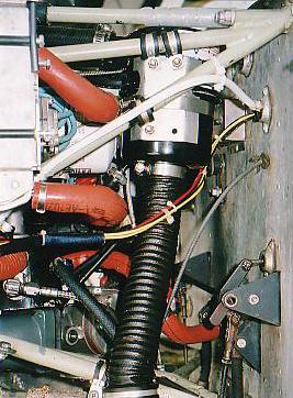
FOR REFERENCE ONLY. Applicability: BEECHCRAFT [VACUUM GYRO SYSTEMS ONLY] Drawing: AFC-W301
![FOR REFERENCE ONLY. Applicability: BEECHCRAFT [VACUUM GYRO SYSTEMS ONLY] Drawing: AFC-W301](/thumbs/94/119029096.jpg "FOR REFERENCE ONLY. Applicability: BEECHCRAFT [VACUUM GYRO SYSTEMS ONLY] Drawing: AFC-W301") FOR REFERENCE ONLY Applicability: BEECHCRAFT [VACUUM GYRO SYSTEMS ONLY] Drawing: AFC-W301 Airwolf Parts List No. AFC-W301-A Index Part Number Description Quantity 01. W-3000 AirSep Assy, 3/4" Breather,
FOR REFERENCE ONLY Applicability: BEECHCRAFT [VACUUM GYRO SYSTEMS ONLY] Drawing: AFC-W301 Airwolf Parts List No. AFC-W301-A Index Part Number Description Quantity 01. W-3000 AirSep Assy, 3/4" Breather,
FOR REFERENCE ONLY. Applicability: Piper Aztec Drawing: AFC-W327 Without Deice Boots Revision: B Date: 06/01/05
 FOR REFERENCE ONLY Applicability: Piper Aztec Drawing: AFC-W3 Without Deice Boots Revision: B Date: 06// Airwolf Parts List No. AFC-W3-A Index Part Number Description Quantity. W- AirSep Assy, 1 Breather,
6: PA32-260, PA32-300, PA32S-300
 1 3 4 6 7 8 9 10 11 12 20 21 2 5 22 14 24 15 07 23 17 16 25 18 19 26 27 28 FOR REFERENCE ONLY Applicability: PIPER [Non Turbo Charged] Drawing: AFC-W315 Lance: PA32R-300, PA32RT-300 Saratoga: PA32-301,
AIRWOLF FILTER CORP Madison Rd. Middlefield, Ohio U.S.A. (440) / (440) Fax
 / (440) Fax") AIRWOLF FILTER CORP. 15369 Madison Rd. Middlefield, Ohio 44062-8404 U.S.A. (440) 632-5136 / (440) 632-1685 Fax TO THE MECHANIC: This P/N AFC-K010 remote mount oil filter kit incorporates our generic STC
AIRWOLF FILTER CORP. 15369 Madison Rd. Middlefield, Ohio 44062-8404 U.S.A. (440) 632-5136 / (440) 632-1685 Fax TO THE MECHANIC: This P/N AFC-K010 remote mount oil filter kit incorporates our generic STC
Oil Filter Kit AFC-K005
 22. 21. 20. 12. 03. 04. 06. 07. 24. 11. 05. 09. 08. 02. 01. 17. 19. 18. 23. 25. 13. 14. 15. 10. 11. 16. Oil Filter Kit AFC-K005 27. 26. Applicability: Aviat Husky Model A-1 with Lycoming First Release:
BEECHCRAFT [PRESSURE GYRO SYSTEMS ONLY]
![BEECHCRAFT [PRESSURE GYRO SYSTEMS ONLY]](/thumbs/89/97844284.jpg "BEECHCRAFT [PRESSURE GYRO SYSTEMS ONLY]") 1 2 3 4 24 25 20 6 7 8 9 5 10 13 14 15 16 22 23 21 18 11 12 17 19 28 27 26 pplicability: BEECHCRFT [PRESSURE GYRO SYSTEMS ONLY] Drawing: FC-W304 36 [S/N E-716, E-732 & fter] Date: 06/01/05 [S/N CE-602
1 2 3 4 24 25 20 6 7 8 9 5 10 13 14 15 16 22 23 21 18 11 12 17 19 28 27 26 pplicability: BEECHCRFT [PRESSURE GYRO SYSTEMS ONLY] Drawing: FC-W304 36 [S/N E-716, E-732 & fter] Date: 06/01/05 [S/N CE-602
Oil Filter Kit AFC-K003
 03 16a / 16b 17 18 06 04 07 08 05 09 12 01 15 13 02 14 21 22 20 23 10 11 24 25 19 Oil Filter Kit AFC-K003 Applicability: Robinson Model R-22 with Lycoming First Release 10/05/92 Engines O-320 & O-360 Amended
Oil Filter Kit AFC-K001
 Oil Filter Kit AFC-K001 Applicability: Homebuilt Aircraft using Lycoming O-235, 290, 320, 340, 360 & 540 First Release 06//84 Engines using the Lycoming P/N 69510, 68974, or 62815 4-bolt NEW oil screen
Oil Filter Kit AFC-K012
 01 02 03 20a 04a 05 07 08 09 04b 10 20b 20c 06 15 16 17 18 19 11 12 14 13 Oil Filter Kit AFC-K012 Applicability: Hiller Helicopter Model UH12A, 12B, 12C, 12D, 12E, &12L4 First Release 11/01/95 with Franklin
Oil Filter Kit AFC-K004
 16 01 03 13 17 05 06 02 15 18 04 07 09 08 12 19, 20, 21 10 Oil Filter Kit AFC-K004 11 Applicability: Schweizer Model 269 A, B, C & 300C with Lycoming Engines First Release 12/05/92 HO-360-B1A, HO-360-B1B,
Power Flow System Extractor Exhaust System Installation Instructions Cessna 172, 175 TABLE OF CONTENTS
 Heading Power Flow System Extractor Exhaust System Installation Instructions TABLE OF CONTENTS Pages Introduction 3 Kit Contents Classic Tailpipes 4 Kit Contents Short Stack Tailpipes 5 Preparation 6 Removal
FOR REFERENCE ONLY. Applicability: CESSNA [Right Engine] Drawing: AFC-W320 Revision: B 411, 411A Date: 06/01/05
![FOR REFERENCE ONLY. Applicability: CESSNA [Right Engine] Drawing: AFC-W320 Revision: B 411, 411A Date: 06/01/05](/thumbs/93/112679650.jpg "FOR REFERENCE ONLY. Applicability: CESSNA [Right Engine] Drawing: AFC-W320 Revision: B 411, 411A Date: 06/01/05") FOR REFERENE ONLY pplicability: ESSN [Right Engine] Drawing: F-W320 Revision: 411, 411 Date: 06/01/05 irwolf Parts List No. F-W320-R Index Part Number Description Quantity 01. W-3003 irsep ssy (1) 02.
FOR REFERENE ONLY pplicability: ESSN [Right Engine] Drawing: F-W320 Revision: 411, 411 Date: 06/01/05 irwolf Parts List No. F-W320-R Index Part Number Description Quantity 01. W-3003 irsep ssy (1) 02.
Revision Control Page REPORT PFS Kit PFS REVISION DATE REMOVE PAGES
 Revision Control Page REPORT PFS-0020-00 Kit PFS-13203 REVISION DATE REMOVE PAGES INSERT PAGES IR 06/27/00 N/A N/A A 09/21/00 1,2,4,14 1,2,4,14 B 02/12/01 1,2,4,8,9,13 1,2,4,8,9,13 C 09/14/01 1,2,3,4,5,6,7,8
2.0 KIT CONTENTS INSTALLATION OF PFS EXHAUST SYSTEM INSTRUCTIONS FOR CONTINUED AIRWORTHINESS PASSENGER SIDE VIEW...
 TABLE of CONTENTS 1.0 INTRODUCTION... 3 1.1 GENERAL... 3 1.2 DESCRIPTION... 3 1.3 UPGRADES... 3 2.0 KIT CONTENTS... 4 2.1 CLASSIC TAILPIPE KITS... 4 2.2 SHORT STACK TAILPIPE KITS... 5 3.0 PREPARATION...
TABLE of CONTENTS. PFS REV C Page 2 of 20 05/22/07
 Section TABLE of CONTENTS Pages Introduction 3 Kit Contents 4 Preparation 5 Removal of old exhaust system 5 Installation 5 Installing Collector Box Assembly and Exhaust Assembly 5 Installing Cabin Heat
PARAVION TECHNOLOGY, INC AIRWAY AVENUE FORT COLLINS, COLORADO REPORT NO. PR-206H-900M CABIN HEATER SYSTEM INSTALLATION INSTRUCTIONS
 PARAVION TECHNOLOGY, INC. 2001 AIRWAY AVENUE FORT COLLINS, COLORADO 80524 REPORT NO. CABIN HEATER SYSTEM INSTALLATION INSTRUCTIONS BELL 206A/B HELICOPTERS Page i PR- Rev. P, 04/06/09 REVISIONS REV. DATE
For Experimental Aircraft Only: Glastar, Sportsman 2+2, and Similar with Lycoming O320 or O360 Parallel Valve Engines
 REPORT NAME: KIT PFS-16104 INSTALLATION INSTRUCTIONS AND INSTRUCTIONS FOR CONTINUED AIRWORTHINESS APPROVAL PFS ENG DATE: REPORT NUMBER: PFS-16250-EXP REVISION: A REPORT DATE: 02/14/06 PREPARED BY: Tom
LYCOMING A Textron Company
 LYCOMING AEIO-360-HB PARTS CATALOG This illustrated parts catalog contains a complete parts listing for the Lycoming AEIO-360-HB wide cylinder flange crankcase model aircraft engines. Major assembly and
TABLE of CONTENTS PFS-15102
 Section TABLE of CONTENTS PFS-15102 Installation Instructions and Page 1.0 INTRODUCTION...3 2.0 KIT CONTENTS...4 3.0 PREPARATION...5 4.0 INSTALLATION OF PFS EXHAUST SYSTEM...5 4.1 - Installing Collector
D'Shannon Products, Ltd County Road 134 Buffalo, MN Supplemental Type Certificate SA2200SW. Installation Instructions
 1992 D'Shannon Products, Ltd. Supplemental Type Certificate SA2200SW Installation Instructions Teledyne Continental IO-520-B, -BA, -BB and IO-550-B Engines Series II Beechcraft 35 and 33 Airplanes Eligible
PARAVION TECHNOLOGY, INC AIRWAY AVENUE FT. COLLINS, COLORADO 80524
 [Rev. 5, 11/07/07] PARAVION TECHNOLOGY, INC. 2001 AIRWAY AVENUE FT. COLLINS, COLORADO 80524 INSTRUCTIONS FOR CONTINUED AIRWORTHINESS 407H-120M BLEED-AIR CABIN HEATER INSTALLATION BELL MODEL 407 HELICOPTERS
REVISION DESCRIPTION:
 REVISION DESCRIPTION: 14401 Keil Road NE, Aurora, Oregon, USA 97002 PHONE 503-678-6545 FAX 503-678-6560 www.vansaircraft.com info@vansaircraft.com Service Letters and Bulletins: www.vansaircraft.com/public/service.htm
Lycoming AIRCRAFT ENGINES. IO-540-AC1A5 Wide Series Flange Crankcase Model Engine PARTS CATALOG PC
 AIRCRAFT ENGINES IO-540-ACA5 Wide Series Flange Crankcase Model Engine PARTS CATALOG PC-5- November 008 Lycoming 5 Oliver Street Williamsport, PA 770 U.S.A. 570/33-8 IO-540-ACA5 PARTS CATALOG This illustrated
MODIFICATION KIT. Serial Numbers 300 (LC40-550FG) thru (LC42-550FG) thru (LC41-550FG) thru
 thru (LC42-550FG) thru (LC41-550FG) thru") Single Engine MODIFICATION KIT MK400-71-01 TITLE ENGINE OIL COOLER WINTERIZATION MODIFICATION EFFECTIVITY Model Serial Numbers 300 (LC40-550FG) 40004 thru 40079 350 (LC42-550FG) 42001 thru 421018 400 (LC41-550FG)
Single Engine MODIFICATION KIT MK400-71-01 TITLE ENGINE OIL COOLER WINTERIZATION MODIFICATION EFFECTIVITY Model Serial Numbers 300 (LC40-550FG) 40004 thru 40079 350 (LC42-550FG) 42001 thru 421018 400 (LC41-550FG)
Instructions for Continued Airworthiness
 Forced Aeromotive Technologies Instructions for Continued Airworthiness Supercharged IO-550-N Engines Installed On NOTICE This document must be referenced on Block 8 of FAA form 337 and added to the aircraft
Lycoming Aircraft Engines Parts Catalog
 Aircraft Engines Parts Catalog IO-0-BG Wide Cylinder Flange Crankcase Model Engine Part No. PC-0- Oliver Street Williamsport, PA 770 Aircraft Engines Parts Catalog IO-0-BG Wide Cylinder Flange Crankcase
PUBLICATION REVISION
 Lycomlng 65 Oliver Street Williamsport, PA 770 U.S.A. 77/-6 TECHNICAL PUBLICATION REVISION REVISIOI No. PUBLICATION PUBLICATION No. PUBLICATION DATE IO-60-LA PC-06-A Engines PC-06- MAY, 996 This page(s)
HARTZELL PROPELLER INC.
 HARTZELL PROPELLER INC. One Propeller Place Piqua, Ohio 45356-2634 U.S.A. Telephone: 937.778.4200 Fax: 937.778.4391 MANUAL REVISION TRANSMITTAL Manual (61-00-11) Propeller Owner's Manual and Logbook REVISION
Chapter 79. Oil System
 Chapter 79 Oil System PAGE 1 TABLE OF CONTENTS Chapter Title 79-00-00 GENERAL.................................. 3 79-00-10 Christen Inverted Oil System..................... 3 79-00-11 Valve Balls...................................
Service Letter. Service Letter No. 060 CD Series Combustion Heater Fuel Shroud & Hardware Supersedure. 1. Planning Information
 2900 Selma Highway Montgomery, AL 36108 USA Tel: 334-386-5400 Fax: 334-386-5450 Service Letter CD Series Combustion Heater Fuel Shroud & Hardware Supersedure 1. Planning Information A. Effectivity (1)
2000 SERIES SPEEDBRAKE INSTALLATION MANUAL MOONEY M20 SERIES & M22 STC NO. SA4342NM NOTE: READ THESE DIRECTIONS BEFORE STARTING!
 INSTALLATION REPORT NO. 08059 Serial Number PRECISE FLIGHT, INC. 800-547-2558 2000 SERIES SPEEDBRAKE INSTALLATION MANUAL MOONEY M20 SERIES & M22 NOTE: READ THESE DIRECTIONS BEFORE STARTING! THIS DOCUMENT
SAMPLE BLUE STAR CONVERSION INSTALLATION OF CONTINENTAL IO-470-N IN H35 BONANZA SERIAL NUMBER D-4866 THROUGH D-5330 LWS 470-H35 STC # SA2660SW
 BLUE STAR CONVERSION INSTALLATION OF CONTINENTAL IO-470-N IN H35 BONANZA SERIAL NUMBER D-4866 THROUGH D-5330 LWS 470-H35 STC # SA2660SW SAMPLE BLUE STAR CONVERSION TABLE OF CONTENTS PAGE DESCRIPTION PAGE
Auxiliary Dry Air Pump Kit No. AP Merrill Field Drive Instructions for Continued Airworthiness LOG OF REVISIONS
 LOG OF REVISIONS REVISIONS PAGES REVISED AND APPROVAL NO. DATE DESCRIPTION OF REVISIONS SIGNATURE -- 4/20/90 Original Issue ---- A 1/10/98 All pages revised and reissued per ECO AT-50, dated January 10,
SERVICE INSTRUCTION SI Revision 1
 SERVICE INSTRUCTION SI-79-01 Revision 1 20 Tube Oil Cooler Retrofit SUBJECT / REASON / DESCRIPTION: This service instruction describes the replacement of the 18 tube oil cooler with a 20 tube oil cooler.
TABLE of CONTENTS. Installation Instructions and Instructions for Continued Airworthiness PFS-17101
 TABLE of CONTENTS Section Page 1.0 Introduction... 3 1.1 Description... 3 1.2 Update Procedure... 3 2.0 Kit Contents... 4 3.0 Preparation... 5 4.0 Installation of PFS Exhaust System... 5 4.1 Installing
2003 Lycoming. All rights reserved. Lycoming and "Powered by Lycoming" are trademarks or registered trademarks of Lycoming.
 O-50-AD5 Engine Parts Catalog Lycoming Part Number: PC-55-3 003 Lycoming. All rights reserved. Lycoming and "Powered by Lycoming" are trademarks or registered trademarks of Lycoming. All brand and product
Airglas, Inc. MANUAL NO. GLH AHSA. MODEL GLH3000 Ski Kit Actuated by Wipaire, Inc. Amphibious Float Hydraulic System
 Airglas, Inc. Amphibious hydraulic system addendum to Instructions for Continued Airworthiness Including Installation, Maintenance and Service Instructions MANUAL NO. GLH3000-105-AHSA MODEL GLH3000 Ski
2000 SERIES PA-30 / PA-39 STC NO. SA00233SE PA-24 STC NO. SA4150NM
 INSTALLATION REPORT NO. 08073 Serial Number PRECISE FLIGHT, INC. 800-547-2558 2000 SERIES SPEEDBRAKE INSTALLATION MANUAL PA-30 / PA-39 STC NO. SA00233SE PA-24 STC NO. SA4150NM NOTE: READ THESE DIRECTIONS
Lycoming Aircraft Engines Parts Catalog
 Lycoming Aircraft Engines Parts Catalog TIO-360-CA6D Wide Cylinder Flange Models Part No. PC-06-3 65 Oliver Street Williamsport, PA 770 Lycoming Aircraft Engines Parts Catalog TIO-360-CA6D Wide Cylinder
Page REV 1: Added 'Step 2: See the "REMOVE THIS TAB, BOTH SIDES" callout near Detail A. Modify four SB375-4 Snap Bushings as shown.
 14401 Keil Road NE, Aurora, Oregon, USA 97002 PHONE 503-678-6545 FAX 503-678-6560 www.vansaircraft.com info@vansaircraft.com Service Letters and Bulletins: www.vansaircraft.com/public/service.htm REVISION
2000 SERIES SPEEDBRAKE INSTALLATION MANUAL PA28/PA32 STC # SA00762SE
 INSTALLATION REPORT NO. 08067 Serial Number PRECISE FLIGHT, INC. 800-547-2558 2000 SERIES SPEEDBRAKE INSTALLATION MANUAL PA28/PA32 STC # SA00762SE NOTE: READ THESE DIRECTIONS BEFORE STARTING! CHECK FOR
Airglas, Inc. Installation Instructions. MANUAL NO. LH MODEL LH4000 Ski Kit For Cessna 180 and 185 Aircraft.
 Airglas, Inc. Installation Instructions MANUAL NO. LH4000-105 MODEL LH4000 Ski Kit For Cessna 180 and 185 Aircraft Cage Code 17564 This Page Intentionally Left Blank 2 P a g e REV LEVEL Initial Release
500W Series Instructions for Continued Airworthiness
 Instructions for Continued Airworthiness Document Number Garmin International, Inc. 1200 E. 151st Street Olathe, Kansas 66062 USA Record of Revision Rev. Date Description of Change 1 10-19-06 Initial Release
TEXTRON Lycoming AIRCRAFT ENGINES
 TEXTRON Lycoming AIRCRAFT ENGINES O-60-AP Wide Cylinder Flange Crankcase Model Engines PARTS CATALOG PC-06-6 MARCH 99 0-60-AP PARTS CATALOG This illustrated parts catalog contains a complete parts listing
O-540-F1B5 SERIES PARTS CATALOG WIDE CYLINDER FLANGE CRANKCASE MODEL ENGINES
 INTRODUCTION This illustrated parts catalog contains a complete parts listing for the Lycoming O-540-F1B5 series wide cylinder flange crankcase model aircraft engines. Major assembly and sub-assembly parts
Power Flow System Extractor Exhaust System Instructions for Continued Airworthiness PFS-13201
 REVISION CONTROL REVISION DATE REMOVE PAGES INSERT PAGES IR 09/12/01 N/A N/A A 10/05/01 ALL ALL B 02/26/02 1-3,5,6,8,10 1-3,5,6,8,10 C 08/30/02 1-5,7,10 1-5,7,10 D 01/15/03 ALL ALL E 7/2/04 1,4,5 1,4,5
Instructions for Continued Airworthiness for the Installation of the HD Extended Maule Main Gear Assembly ABI-4022X
 ABI-4022X-ICA-RevC Instructions for Continued Airworthiness for the Installation of the HD Extended Maule Main Gear Assembly ABI-4022X Document Number: ABI-4022X-ICA Revision C 02/17/12 02/17/12 ABI-4022X-ICA
Appendix B. TORQUE SPECIFICATIONS CONTENTS. Appendix B. Torque Specifications... B-1 B-1. General Information... B-2
 Appendix B. TORQUE SPECIFICATIONS CONTENTS Appendix B.... B-1 B-1. General Information... B-2 B-1.1. Torque Tips...B-2 B-2. Cylinder Torque Procedure... B-3 B-3. Torque Wrench and Extension Calculations...
182T and T182T Back-Up Alternator System ICA Revision: Date: 17 September 2008
 Document Number: NC-08-034 Title: 182T and T182T Back-Up Alternator System ICA Revision: C Date: 17 September 2008 Name Signature Date Author Erik Pederson Signed Copy On File 9/17/08 Approved Erik Pederson
performance S T O L Installation Instructions Manual No. PSTOL-013 Double Slotted Flaps for Piper PA-18 Series Aircraft
 performance S T O L Installation Instructions Manual No. PSTOL-013 Double Slotted Flaps for Piper PA-18 Series Aircraft 1 This Page Intentionally Left Blank 2 Record of Revisions Rev Level Date Page By
NC Kit # CE-182PQR-00 Air-conditioning installation manual and ICA for Cessna 182 P, Cessna 182 Q and Cessna 182 R
 NC-04-041 Kit # CE-182PQR-00 Air-conditioning installation manual and ICA for Cessna 182 P, Cessna 182 Q and Cessna 182 R REVISION: E Date: November 10, 2004 Name Signature Date Author Len Elder 10/25/2004
IO-540-K1H5 Series Illustrated Parts Catalog
 IO-50-KH5 Series Illustrated Parts Catalog November 983 Engine model IO-50-KK5, previously covered in this parts catalog, has been superseded by PC-5-KK5. PC-5-03 5 Oliver Street Williamsport, PA 770 IO-50-KH5
REVISION LIST CHAPTER 26: FIREWALL FORWARD (PART II)
") REVISION LIST CHAPTER 26: FIREWALL FORWARD (PART II) The following list of revisions will allow you to update the Legacy construction manual chapter listed above. Under the Action column, R&R directs you
REVISION LIST CHAPTER 26: FIREWALL FORWARD (PART II) The following list of revisions will allow you to update the Legacy construction manual chapter listed above. Under the Action column, R&R directs you
Instructions for Continued Airworthiness
 . Instructions for Continued Airworthiness for the installation of THE GROVE DISC BRAKE CONVERSION in all PIPER AIRCRAFT INCLUDED IN THE FAA APPROVED MODEL LIST when installed In Accordance With Supplemental
O-540-A4B5 PARTS CATALOG WIDE CYLINDER FLANGE CRANKCASE MODEL ENGINES
 INTRODUCTION This illustrated parts catalog contains a complete parts listing for the Lycoming O-540-A4B5 wide cylinder flange crankcase model aircraft engines. Major assembly and sub-assembly parts of
O-320-H 76 Series Illustrated Parts Catalog
 O-320-H 76 Series Illustrated Parts Catalog PC-122-H 76 Series 2013 652 Oliver Street Williamsport, PA 17701 O-320-H 76 Series Illustrated Parts Catalog PC-122-H 76 Series 2013 652 Oliver Street Williamsport,
Contains Important Information Pertaining to Your Aircraft Engine Compliance Will Enhance Safety
 CONTINENTAL MOTORS AIRCRAFT ENGINE SERVICE ULLETIN Contains Important Information Pertaining to Your Aircraft Engine Compliance Will Enhance Safety Category 3 S09-4 Supersedes S09-4A TECHNICAL PORTIONS
PARAVION TECHNOLOGY, INC AIRWAY AVENUE FT. COLLINS, COLORADO 80524
 PARAVION TECHNOLOGY, INC. 2001 AIRWAY AVENUE FT. COLLINS, COLORADO 80524 REPORT NO. PR-369DA-900M PNEUMATIC DOOR OPENER INSTALLATION INSTRUCTIONS FOR 369PDO-100 369, 500N & 600N HELICOPTERS Page i REVISIONS
Install manual/service Letter
 Install manual/service Letter Doc No: NC-08-006 Rev D 1625 Lost Nation Rd., Willoughby, OH 44094 PH: 440-951-4744 FAX:440-951-4725 Issue Date: 16 May 2008 EFFECTIVITY Cessna Aircraft Types: 182T, T182T
AVIAT AIRCRAFT INC. P.O. Box South Washington Afton, WY USA Fax:
 DATE: 18 December 2000 REVISION: Orig. AIRCRAFT: PITTS SPECIAL P.O. Box 1240 672 South Washington Afton, WY 83110 USA 307-886-3151 Fax: 307-885-9674 aviat@aviataircraft.com SUBJECT: Propeller Accumulator
Service Bulletin No.: DAC Rev 5 Date Issued: 26 November 2010 Title: Engine Fuel System Conversion from IO-240-B17B to IO-240-B3B
 Page: 1 of 10 1. ATA Code: 7300 2. Effectivity: DA20-C1 S/N C0380 to C0456, C0467 to C0471, C0482 to C0488, C0496, C0497, C0504, C0505, C0511 to C0513 and C0536 or earlier aircraft on which SB DAC1-73-01
TEXTRON Lycoming AIRCRAFT ENGINES
 TEXTRON Lycoming AIRCRAFT ENGINES O-60-CF & -CP Wide Cylinder Flange Crankcase Model Engines PARTS CATALOG PC-06- OCTOBER 995 65 Oliver Street Williamsport, PA 770 U.S.A. 77/-6 Lycoming O-60-CF &-CP PARTS
Installation and Operation Manual. Manufacturers of Innovative Materials Handling Equipment since 1957.
 SWINGSET DISTRIBUTOR Installation and Operation Manual Manufacturers of Innovative Materials Handling Equipment since 1957. 491 North Emerson Street * Cambridge MN 55008-1316 U.S.A. Toll Free (800) 328-8002
SERVICE BULLETIN No.: S , Rev. 0 Date: January 3, 2008
 Technical portions are FAA-approved. SUBJECT: S539800 STARTER ADAPTER CLUTCH SPRINGS and STARTER MOTORS PURPOSE: COMPLIANCE: MODELS AFFECTED: To provide owners and operators with Instructions for Continued
LANCAIR LEGACY PRE-TEST FLIGHT INSPECTION (8-04)
") LANCAIR LEGACY PRE-TEST FLIGHT INSPECTION (8-04) OWNER PHONE # ADDRESS N SERIAL # AIRCRAFT TYPE DATE / / TACH TIME hrs. TOTAL TIME hrs. EMPTY WEIGHT CG. PAINT & INTERIOR? YES NO ENGINE TYPE PROPELLER ALL
LANCAIR LEGACY PRE-TEST FLIGHT INSPECTION (8-04) OWNER PHONE # ADDRESS N SERIAL # AIRCRAFT TYPE DATE / / TACH TIME hrs. TOTAL TIME hrs. EMPTY WEIGHT CG. PAINT & INTERIOR? YES NO ENGINE TYPE PROPELLER ALL
Page: REV 3: Add drill and tap information to Figure 4 DRILL #3, TAP 1/4-28 BOTH ENDS.
 REVISION DESCRIPTION: 1) Page: 32-03 MEMO: Step 4 should not be bold. Fix WD-1213 callout in Figure 3. Page: 32-04 REV 3: Add drill and tap information to Figure 4 DRILL #3, TAP 1/4-28 BOTH ENDS. Add make
Installation of C-2052, C , C or C Governor and "T" Drive Kit on Bonanza
 INSTRUCTIONS NO. 1A Installation of C-2052, C-2052-1, C-2052-2 or C-2052-3 Governor and "T" Drive Kit on Bonanza These instructions are provided for the installation of Hartzell "T" drive on Continental
*MANDATORY SERVICE BULLETIN*
 NUMBER: SB-022 REVISION: B DATE: 10/30/2009 SUBJECT: PITOT STATIC SYSTEM; MANDATORY MODIFICATION KODIAK MANDATORY SERVICE BULLETIN *MANDATORY SERVICE BULLETIN* SUMMARY *MANDATORY SERVICE BULLETIN* RECURRENT
INSTRUCTIONS FOR CONTINUED AIRWORTHINESS FAA-STC SE8987SW. Proposal to Increase Lycoming O-320-E2A Engine Power Rating from 150 hp to 160 hp
 INSTRUCTIONS FOR CONTINUED AIRWORTHINESS FAA-STC SE8987SW Proposal to Increase Lycoming O-320-E2A Engine Power Rating from 150 hp to 160 hp Drawing 2663 Notice This document must be referenced on Block
Lycoming Aircraft Engines Parts Catalog
 Aircraft Engines Parts Catalog TIO-540 Series Standard Cylinder Flange Crankcase Models Part No. PC-35-6 652 Oliver Street Williamsport, PA 770 Reciprocating Engine Division/ Subsidiary of Textron Inc.
Operation & Service Manual
 Operation & Service Manual Model: 02-1248-0112 12 Ton Single Stage Jack 11/2004 Rev. 02 Includes Illustrated Parts Lists 1740 Eber Rd Tronair, Inc. Phone: (419) 866-6301 Holland, OH 43528-9794 www.tronair.com
SAMPLE BLUE STAR CONVERSION INSTALLATION OF CONTINENTAL IO-470-C OR IO-470-N BEECH MODELS THROUGH F-33 LWS STC # SA5527SW REVISION 5
 BLUE STAR CONVERSION INSTALLATION OF CONTINENTAL IO-470-C OR IO-470-N BEECH MODELS 35-33 THROUGH F-33 LWS 470-33 STC # SA5527SW REVISION 5 FEBRUARY 5, 1996 BLUE STAR CONVERSION TABLE OF CONTENTS PAGE DESCRIPTION
EA Installation Manual Ignition/Starter Switch Panel For Two Magnetos
 EA-15000 Installation Manual Ignition/Starter Switch Panel For Two Magnetos Electroair Acquisition Corp. 327 Catrell Dr. Howell, MI 48843 U.S.A. Phone: 517-552-9390 Fax: 517-552-9391 Email: sales@electroair.net
IOF-240-B4B ENGINE CONVERSION. All IOF-240-B4B Engines
 SSI--002 REASON FOR ACTION PURPOSE COMPLIANCE MODELS AFFECTED FADEC Software Upgrade. To provide instructions for conversion of all IOF-240-B specification 4B engines to the IOF-240-B specification 5B.
Ignitor supplied with Engine. Power Plant Group - Page 1 (AT-502B) Date: 1/18
 Date: 1/18") 4 9 8 9 48 0 4 4 0 0 4 4 Ignitor supplied with Engine 8 4 4 4 Power Plant Group - Page (AT-0B) Date: / POWER PLANT GROUP - Figure. Power Plant, Engine Mount, Oil Cooler and Ejector Installations 04-8 Engine
4 9 8 9 48 0 4 4 0 0 4 4 Ignitor supplied with Engine 8 4 4 4 Power Plant Group - Page (AT-0B) Date: / POWER PLANT GROUP - Figure. Power Plant, Engine Mount, Oil Cooler and Ejector Installations 04-8 Engine
CONTINENTAL AIRCRAFT ENGINE service bulletin
 CONTINENTAL AIRCRAFT ENGINE service bulletin M83-3 Technical Portions are FAA-DER Approved 14 February, 1983 TO: SUBJECT: MODELS AFFECTED: Aircraft Manufacturers, Distributors, Dealers, Engine Overhaul
CESSNA CITATION MODEL 500/501 INCREASED RAMP AND TAKEOFF WEIGHT INSTALLATION 1 SEPTEMBER 1994
 MAINTENANCE MANUAL SUPPLEMENT NFC Document No. CESSNA MODEL 500/501 INCREASED RAMP AND TAKEOFF WEIGHT INSTALLATION 1 SEPTEMBER 1994 This supplement must be attached to the Cessna Citation Model 500/501
Lycoming Aircraft Engines Parts Catalog
 Aircraft Engines Parts Catalog TIO/LTIO-540-V2AD Wide Cylinder Flange Model Part No. PC-35-2 652 Oliver Street Williamsport, PA 770 Aircraft Engines Parts Catalog TIO/LTIO-540-V2AD Wide Cylinder Flange
REVISION DESCRIPTION:
 14401 Keil Road NE, Aurora, Oregon, USA 97002 PHONE 503-678-6545 FAX 503-678-6560 www.vansaircraft.com info@vansaircraft.com Service Letters and Bulletins: www.vansaircraft.com/public/service.htm REVISION
TIME OF COMPLIANCE: At owner s discretion or when part replacement is necessary.
 52 Oliver Street Williamsport, PA. 770 U.S.A. Telephone + (877) 839-7878 (U.S. and Canada) Telephone + (570) 327-7222 (International) Fax + (570) 327-70 Email Technicalsupport@lycoming.com www.lycoming.com
TECHNICAL PUBLICATION SUPPLEMENT
 TEXTRON Lycoming TECHNICAL PUBLICATION SUPPLEMENT SUPPLEMENT No. ENGINE MODEL PUBLICATION No. PUBLICATION DATE PC-0--B O-90-D Series PC-0- January 9 This supplement is arranged in the same basic format
O-360-A4N Series Illustrated Parts Catalog
 O-360-A4N Series Illustrated Parts Catalog May 2011 PC-306-3 2011 652 Oliver Street Williamsport, PA 17701 Lycoming Part Number: PC-306-3 2011 by Avco Corporation. All Rights Reserved. Lycoming and Powered
Lycoming Aircraft Engines Parts Catalog
 Lycoming Aircraft Engines Parts Catalog AEIO-50-D Series -DA5, -DB5 Wide Cylinder Flange Crankcase Model Engines Part No. PC-5-5 Oliver Street Williamsport, PA 770 Textron Lycoming 5 Oliver Street Williamsport,
INSTALLATION INSTRUCTIONS EXTERNAL AUXILIARY FUEL SYSTEM P/N
 INSTALLATION INSTRUCTIONS EXTERNAL AUXILIARY FUEL SYSTEM P/N 41228-000-002-007 Page 1 of 45 List of Revisions Rev. Date Pages Description Approved IR 09/12/05 All Initial Release N/C All Updated to Apical
EA Instructions for Continued Airworthiness
 EA-15000 Instructions for Continued Airworthiness Electroair 327 Catrell Dr Howell, MI 48843 U.S.A. Ph: 517-552-9390 Fax: 517-552-9391 Email: sales@electroair.net Electroair Acquisition Corp. ICA EA-15000
Printed from Summit Aviation's Computerized Aviation Reference Library, 4/26/2000 Page 1
 98-17-11 Textron Lycoming and Teledyne Continental Motors: Amendment 39-10713. Docket 98-ANE-27-AD. {As corrected at 63 FR 55918 - Ed.} {New-98-10} Textron Lycoming (LYC) O-235, O-235-C1, O-235-C2C, O-235-L2C,
SUBJECT: FUEL SYSTEM FLOW SWITCHES, P/N , , -003, -101 AND -103, REPLACEMENT OF
 ALERT SERVICE BULLETIN 206L-88-52 10 June 1988 Revision A, 26 March 2013 MODEL AFFECTED: 206L and 206L-1 SUBJECT: FUEL SYSTEM FLOW SWITCHES, P/N 206-063- 635-001, 206-064-601-001, -003, -101 AND -103,
RECORD OF REVISIONS. Prepared (name and date) (name and date) 11 November 2011
 (name and date) 11 November 2011") BLADE TIE -DOWN PROVISIONS AS 350 / AS 355 / EC 30 RECORD OF REVISIONS Rev. Pages at this Revision Description, Reason Changed Pages Prepared (name and date) Checked (name and date) App d/acc d (Civil
BLADE TIE -DOWN PROVISIONS AS 350 / AS 355 / EC 30 RECORD OF REVISIONS Rev. Pages at this Revision Description, Reason Changed Pages Prepared (name and date) Checked (name and date) App d/acc d (Civil
Appendix D. Vizion PMA Autopilot Piper PA-28/32 Installation
 Appendix D Vizion PMA Autopilot Piper PA-28/32 Installation RESTRICTION ON USE, DUPLICATION, OR DISCLOSURE OF PROPRIETARY INFORMATION THIS DOCUMENT CONTAINS PROPRIETARY INFORMATION OF TRUTRAK FLIGHT SYSTEMS,
SERVICE BULLETIN. Citation SB TITLE DOORS - WIDE DOOR INSTALLATION MODIFICATION
 TITLE DOORS - WIDE DOOR INSTALLATION MODIFICATION EFFECTIVITY MODEL SERIAL NUMBERS 560 (Citation Encore) -0539 thru -0707 560 (Citation Encore+) -0751 thru -0815 NOTE: This modification may only be accomplished
GROUP E EXPLODED VIEW: EV FUEL SYSTEM 2.4L G2 DRAWING #: 0G1151 ITEM PART# QTY. DESCRIPTION
 EXPLODED VIEW: EV FUEL SYSTEM 2.4L G2 DRAWING #: 0G1151 GROUP E ITEM PART# QTY. DESCRIPTION 1 026915 2 NIPPLE CLOSE 3/4 X 1.375 2 075580 1 FLANGE FUEL INLET 3 0F6390C 1 REGULATOR ASSY 2.4L (25KW) 0F6390B
Electronic Service Manuals
 Electronic Service Manuals This electronic document is provided as a service to our customers. We do not create the contents of the information contained in this document. Should you have detailed questions
DISC BRAKE/DUAL MASTER CYLINDER CONVERSION. Tools, Equipment and Supplies Needed:
 Please take the time to read the enclosed instructions carefully. If you have any questions, call our Product Assistance personnel for clarification. It is important to note that these instructions contain
MANPOWER REQUIREMENTS
 CIRRUS SF5X Service Bulletin Number: Issued: Revised: 09 Aug 208 SNS SUBJECT: 25-0 CABIN - Armrest Installation. COMPLIANCE Optional: Accomplishment of this Service Bulletin is at the owner s option. This
Airglas, Inc. Instructions for Continued Airworthiness Including Installation, Maintenance and Service Instructions MANUAL NO.
 Airglas, Inc. Instructions for Continued Airworthiness Including Installation, Maintenance and Service Instructions MANUAL NO. PA-32-105 PA-32LA 8.00x6 NOSE WHEEL INSTALLATION KIT For Piper PA-28 and PA-32
BACKGROUND: To provide information relating to the TT strap installation installed in the piston helicopters under Airwolf STC SH03465CH.
 BACKGROUND: To provide information relating to the TT strap installation installed in the piston helicopters under Airwolf STC SH03465CH. Enstrom helicopters delivered new from the factory starting in
SERVICE BULLETIN SB00029 Rev B Page 1 of 19
 SERVICE BULLETIN SB00029 Rev B Page 1 of 19 This Service Bulletin meets requirements of ASTM F2295-06. It is a Safety Directive for the purpose of compliance with 14 CFR 91.327(b)(4). EFFECTIVE DATE: This