Installation and Operations Manual
|
|
|
- Aldous Rose
- 5 years ago
- Views:
Transcription
1 Excalibur Water Systems 2.0 HIGH CAPACITY SUPER FLOW SERIES DUPLEX WATER SOFTENER Installation and Operations Manual 142 Commerce Park Drive, Units M-O, Barrie ON L4N 8W8
2 2.0 High Capacity Premium Flow Series Water Softener: Premium flow water softener AC adapter for European use. 1. Water softener VAC 50Hz input 24.0 VAC 750 MA output. 2. Water softener cable should be one unshielded pair of 22 AWG, UV Resistant UL2464 compliant wire. 3. Water softener connector details: A) Terminate end with one Molex white housing. P/N CLN and four Molex pins. P/N CLN B) Water softener Pin 1 = 24.0 VAC Water softener Pin 2 = Jumper to Pin 3 Water softener Pin 3 = Jumper to Pin 2 Water softener Pin 4 = 24.0 VAC Black 1
3 Water Softener Custom Meter Wiring: 1. Water softener terminate end with a Molex series 2695 housing, Pin and (3) Molex series (or 40445) Pins, Pin (or ). 2. Water auxiliary meter must be able to operate on 5VDC. Water softener Pin 1 = + 5VDC Water softener Pin 2 (centre) = SIGNAL Water softener Pin 3 = GROUND 3) Water softener acceptable pulse input is pulse/gallon, or pulses/litre. 12
4 Water Softener Optional System Board: Water softener system board required for relay output and separate source inlet. 1) Water softener relay outlets 1 and 2 are normally open SPST dry contacts. 2) Water softener maximum power through water softener relays to be a) 1A, 30VDC b) 1A, 30VAC 3) Water softener separate souce inlet dreives require connection to a P/N 3063 or P/N 3063 BSPT motorized alternating valve (MAV) 13
5 Water Softener Motorized Drive Operation: Viewing the water softener piston rod through the clear water softener clear dome is a visual indicator of the water softener drives current position. On the water softener motorized bypass drive, viewing the rod indicates that the water softener is in service. Viewing the water softener rod as shown on the water softener MAV indicates that the water softener common port is currently connected to the water softener B port. If the water softener rod is not visible the water softener is offline in the case of a bypass, or connected to the water softener A port of a MAV. This water softener drive logic is reversible to meet specific plumbing applications by reversing the polarity of the water softener drive motor wiring harness as shown below. 14
6 Water Softener Reversing Motorized Drive Direction: Water softener motorized bypass and water softener MAV drives are factory wired with the white wire on the right when viewing the water softener wiring harness as shown, reversing the water softener wires reverses the logic of the drive. The water softener wires can be removed from the housing by holding down the water softener locking tab in the small window while applying light pressure to the wire, being careful not to disengage the wire from its crimped on connector. The water softener wires can then be reinserted, being sure the water softener locking tab re-engages in the window. 15
7 Water Softener Wiring Diagram Examples 2 Water Softener System: Water softener dual system with optional system optional system board for water softener relays outputs and separate source inlet. 16

8 Water softener 3 and 4 unit systems with no optional system boards (4 water softener shown) 17
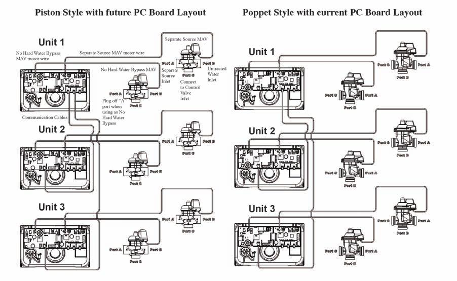
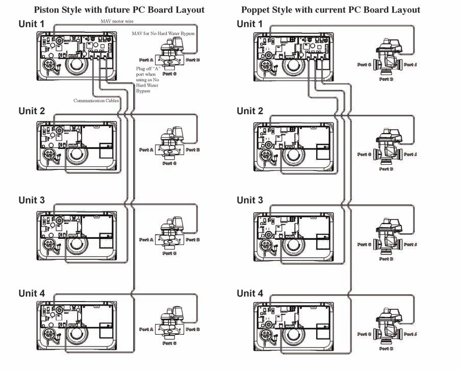
9 18

10 Water softener 3 and 4 unit systems with optional systems boards for water softener relay outputs and separate inlet (4 water softeners shown) 19
11 Water Softener Programming Screen Quick Reference: 1. Water softener individual screen descriptions are detailed on the following pages. 2. Some water softener screens have been omitted for clarity. 110
12 111
13 112

14 Water Softener Setting Time of Day: Water softener set time accessed by pressing set lock while in the water softener user screen. Use the up and down water softener arrows to scroll hours. This water softener AM/PM alternates at midnight. Water softener count error and the water softener number will flash when it is not detected. Pressing any button will return the user to the water softener set up screen to correct the valve. Water softener error screen: Water softener error and the code alternate. The water softener returns and flashes it s 3 LED s. The water softener continues to try and function, but must be reset to correct the water softener error screen. 113
15 Water Softener Typical User Screens: Water softener regen today wil display when a regeneration is scheduled or flash for a manually set regeneration. Water softener user 1 displays capacity remaining. Does not display if volumetric capacity is set to OFF. Water softener capacity remaining can be adjusted in 10 gallon increments by holding the water softener down arrow for > 3 seconds. Water softener displays days remaining does not display if days override is set to OFF. The water softener days remaining can be decremented one day at a time by holding the water softener down arrow > 3 seconds. Water softener displays time of day. Water softener hold or start regen will flash in all user screens while the water softener auxiliary input is activated Water softener displays the current flow rate. 114

16 Water Softener Typical User Screens Continued: Water softener displays total water softener volume since install/reset individually re-settable using history reset sequence. Water softener displays the water softeners current system flow rate. The water softener does not display on single tank water softeners. Water softener total system volume since install/reset individually re-settable using history reset sequence. The water softener does not display on single tank water softener. 115

17 Water Softener System Set Up Screens: Water softener accessed by pressing next and down simultaneously for > 3 seconds. Water softener select country US or SI. This sets the water softener use of 12 or 24 hour clock and the water softener display of gallons or litres. Select the water softener total number of water softener tanks from 1-4, in a water softener system. This water softener screen will only allow 1 or 2 if a water softener system board is not installed. Select water softener flow rate and water softener add point. 1. If water softener is set to 0, all the water softeners are online, unless one is regenerating. 2. If the water softener is greater than 0, the water softener acts as an alternator water softener, keeping one water softener offline at all times. The water softener screen will not display if set to one water softener. 116


18 Single water softeners have a selection of hard water bypass, no hard water bypass or water softener relay operation. When the water softeners start to regenerate, the water softener hard water bypass will allow hard water bypass, no hard water bypass or water softener relay and two water softeners alternators have an additional selection of ALT-A setting the water softener no hard water bypass requires a motor driven water softener bypass. The water softener ALT-A requires a motor driven alternator valve on the controlling water softener and relay relies on external valving for no hard water bypass control. The water softener select day control type, time clock 1-28 days, time clock 7 day, or OFF. When the water softener volumetric capacity is set, volume regeneration can be combined with time clock control. OFF will not be an option if volumetric capacity is off. 117

19 Water Softener Installer Setup Service Returns to Normal Operation After 5 Minutes: The water softener is accessed by pressing the water softener next and down simultaneously for > 3 seconds. Installer 1: Set water softener volumetric capacity or OFF. OFF will not be an option if the water softener day control is set to OFF. x 1000 water softener illuminates at 10,000 gallons. Set water softener current day and regen days when the water softener is set as a 7 day time clock or hybrid in system setup 1. Installer 2: Set water softener day override 1-28 days between regenerations, or if the water softener is set to 7 day time clock, see 7 day water setup below. OFF will display if selected in water softener day control screen installer 3. Select water softener time of regen. Use water softener up and down arrows to scroll hours AM/PM water softener alternates at midnight ONO will be displayed on water softener with no time dependent regen control. 118
20 Installer 4: Select water softener time of regen. Use water softener up and down arrows to scroll minutes. Installer 5: Select water softener time of 2nd water softener regen (if configured as a multiple regenerating water softener). Installer 2: Water softener 7 day time clock option to set water softener current day of the week. 1 - Sunday 2 - Monday 3 - Tuesday 4 - Wednesday 5 - Thursday 6 - Friday 7 - Saturday Installer 2B: Water softener scroll through days 1-7 using the water softener up and down arrows. Pressing the water softener set clock will toggle the water softener regen ON or OFF for that day (ie; regen is on Monday) Installer 2C: (ie; no water softener regeneration on Saturdays) 119
 ONO Water softener delayed with multiple regenerations allowed per day would be used either to reduce the water softener reverse volume, or to accommodate a small water")

21 Water Softener Setup Screens Continued: System Setup 6: Select water softener regeneration type Water softener delayed (DEL-1) Water softener delayed (DEL-2) Water softener delayed (DEL-3) Water softener delayed (DEL-4) ONO Water softener delayed with multiple regenerations allowed per day would be used either to reduce the water softener reverse volume, or to accommodate a small water softener system relative to the treatment demand. System Setup 7: Select water softener reserve calculation ON or OFF. OFF will schedule a regen when the water softener volumetric capacity reaches 0. This water softener screen will not display for ONO Water softener delayed with multiple regenerations allowed per day would be used either to reduce the water softener reverse volume, or to accommodate a small water softener system relative to the treatment demand. System Setup 8: Set water softener auxiliary initiated regen. Start water softener time regen. Regeneration will start immediately after 2 cumulative minutes of switch closure. Start water softener regen: Regeneration will start immediately upon switch closure. Start water softener regen del: regeneration will start at the water softener delayed time upon closure. Hold water softener regen: Regeneration will not be allowed as long as there is switch closure. 120
 Water softener system pulses. System Setup 9B: Select water softener meter type pulses.")

22 System Setup 9: Select water softener meter type or pulses. Water softener 2.0 meter (type) Water softener 1.5 meter (type) Water softener system pulses. System Setup 9B: Select water softener meter type pulses. Water softener screen does not show if pulses or water softener system pulses is not selected in the previous water softener screen. System Setup 10: Water softener separate source inlet. This water softener screen will not display if a water softener system board is not installed. 121
23 Water Softener Time Screens Water Softener Returns to Normal Operation After 5 Minutes: Water softener is accessed by pressing the water softener next and down simultaneously for > 3 seconds, then by pressing next and down simultaneously again for > 3 seconds. Timer 1 - A: Select water softener time of cycle 1. The water softener press next and down reset from this screen unlocks the setup screens. Timer 1 - B: Select water softener time of cycle 2. 1 is displayed if the water softener is set for more than one sequence. The following water softener screens only show if the water softener is programmed for multiple water softener regenerations in the cycle setup 2 screen. Timer 1 - A2 Water softener select time of alternate regen cycle 1 122
24 Timer 1 - B2 Select water softener timer of alternate regen cycle
25 Water Softener Timer Screens Continued: Timer 2: Set water softener output 1, these water softener settings will only be allowed with water softener system board installed. Time: Water softener relay is turned on after the water softener specified time from the start of the water softener regeneration and is left on for a specified time. Cycle: Water softener relay is turned on after the water softener starts on a specified cycle and is left on for a specified time. Volume: The water softener relay is turned on, during the water softener service flow only. Every specified number of water softener volume units and is left on for a specified time. Volume and Regeneration: The water softener relay is turned on every specified number of water softener units and is left on for a specified time. STBY: The water softener relay would be used to control external valving, closing for water softener regeneration, and is left on for a specified time. REGEN: The water softener relay closes when the water softener is in regeneration. ERR: The water softener relay closes when the water softner is in any error mode. 124
26 Water Softener Timer Screens Continued: Timer 3: Set water softener output 2, these water softener settings will only be allowed with water softener system board installed. Time: The water softener relay is turned on after the water softener starts on a specified time from the start of water softener regeneration and is left on for a specified time. Cycle: The water softener relay is turned on after the start of a specified water softener cycle and is left on for a specified time. Volume: The water softener relay is turned on, during the water softener service flow only. Every specified number of water softener volume units and is left on for a specified time. Volume and Regeneration: The water softener relay is turned on every specified number of water softener volume units and is left on for a specified time. STBY: The water softener relay would be used to control external valving, closing for water softener regeneration or when the water softener would be offline in systen operation. REGEN: The water softener relay closes when the water softener is in regeneration. ERR: The water softener relay closes when the water softner is in any error mode. 125
27 Water Softener Timer Screens Continued: Timer 4: Select water softener output 1. On water softener trigger set point per water softener previously selected. This water softener screen will not display if the water softener does not have a water softener system board, or if the water softener STBY was selected as the trigger. Time: The water softener time after the start of water softener regen before switch is closed. Cycle: Select a water softener cycle which will close water softener output 1. Volume: The water softener volume of water interval during service between water softener switch closures. The water softener timer 4 and 6 screens will not display if the water softener display if STBY, REGEN, or ERR are selected in water softener timer 2 and 3. Timer 5: Select water softener output 1 on duration before turning off. This water softener screen will not display if the water softener does not have a water softener system board. 126

28 Water Softener Timer Screens Continued: Timer 6: Select water softener output 2, on water softener trigger set point, per water softener previously selected. This water softener screen will not display if the water softener does not have a water softener system board, or if STBY was selected as the water softener trigger. Time: The water softener time after the start of water softener regen before the water softener switch is closed. Cycle: Select a water softener cycle which will close the water softener output 2. Volume: The water softener volume of water interval during service between water softener switch closures. 127
29 Water Softener Timer Screens Continued: Timer 7: Select water softener output 2 on duration before turning off. This water softener screen will not display if the water softener does not have a water softener system board. 128
30 Water Softener Cycle Setup Screens: Water softener returns to normal operation after 5 minutes. Water softener is accessed by pressing water softener next and down buttons simultaneously for > 3 seconds, then by pressing water softener next and down buttons simultaneously again for > 3 seconds, then by pressing water softener next and down buttons simultaneously again for > 3 seconds a third time. Water softener cycle setup 1 - A Select water softener first cycle. Water softener cycle setup 1 - B Select water softener second cycle. Water softener cycle setup 1 - C After water softener cycles are configured, a water softener end is added. Water softener (9 cycles maximum) 129

31 Water Softener Cycle Setup Screens Continued: Water softener cycle setup 2. Water softener select regeneration repeats, 1-10 or OFF. Water softener repeats regeneration cycle sequence 1 as selected number of times before water softener regenerates a single time with sequence 2. The following watre softener screens only show if the water softener is programmed for multiiple water softener regenerations in the previous water softener screens. Water softener cycle setup 3 - A Select water softener first cycle of alternate water softener regeneration sequence. Water softener cycle setup 3 - B Select water softener second cycle of alternate water softener regeneration sequence. Water softener cycle setup 3 - C After water softener cycles are configured, a water softener end is added, water softener (9 cycles maximum) 130
32 Water Softener Diagnostic Screens: Return water softener to normal operation after 5 minutes. Water softener is accessed by pressing water softener next and down buttons simultaneously for > 3 seconds. All water softener diagnostic history screens are resettable with the water softener history reset sequence while in the water softener diagnostics 1 screen. Holding the water softener set clock and water softener regen buttons for > 3 seconds initiates a totalizer or history reset. Water softener diagnostics 1 = days since the last water softener regeneration Water softener diagnostics 2 Water softener gallons or litres since the last water softener regeneration Water softener diagnostics 3 Water softener reserve history - this water softener screen onlly appears if valve is set to calculate water softener reserve in water softener setup 7. Use arrows to select water softener A day. 0 = today, 1 = yesterday, 6 = 6 days ago (MAX) Water softener reserve valve. Water softener automatically toggles 131
 Water softener regen will display if a water softener regeneration occurs that day.")
33 Water Softener Diagnostic Screens Continued: Water softener diagnostics 4 Water softener history of volume used Use water softener arrows to select A day 0 = today 1 = yesterday 63 = 63 days ago (MAX) Water softener regen will display if a water softener regeneration occurs that day. Water softener gallons used Water softener automatically toggles Simultaneously press water softener up and down buttons Water softener diagnostics 4 - B The water softener hourly history of water softener volume use. Use the water softner up and down buttons to select the water softener hours of the day from water softener screen 4. Water softener volume used within the water softener selected hour. Water softener automatically toggles 132

34 Water Softener Diagnostic Screens Continued: Water softener diagnostics 5 The water softener maximum flow rate for the last 28 days. The water softener maximum flow rate of the day. Water softener automatically toggles Simultaneously press the water softener up and down buttons. Water softener diagnostic 5 - B The water history of maximum flow rate. Use the water softener up and down buttons to select the water softener hours of the day from water softener screen 5. The water softener maximum flow within the watch softener selected hour. Water softener automatically toggles 133
35 Water Softener Diagnostic Screens Continued: Water softener diagnostics 6 Water softener total volume through the water softener. Water softener diagnostics 7 Water softener system totalizer for the last 63 days. Water softener only displays in a mater system. Water softener use for that day Water softener automatically toggles Simultaneously press water softener up and down. Water softener diagnostics 7 - B The water softener hourly system totalizer. Use water softener up and down buttons to select water softener hour of day from water softener screen 7 134
36 Water Softener Diagnostic Screens Continued: Water softener total system flow for the selected hour Water softener automatically toggles 135
37 Water Softener Valve History: Water softener returns to normal operation after 5 minutes non resettable Water softener accessed by pressing water softener up and down buttons simultaneously for > 3 seconds, then by pressing water softener up and down buttons simultaneously again for > 3 seconds. Water softener history 1 Water softener total days since startup. Water softener time only accumulates while the water softener is plugged in. Water softener history 2 Water softener total regenerations since startup. Water softener history 3 Water softener total volume since startup. 136
38 Water Softener Error Codes: 137
Water Specialist EE Control Valve Programming and Cover Drawing Manual
 Water Specialist EE Control Valve Programming and Cover Drawing Manual Page 2 EE Man u al EE Man u al Page 3 Table of Contents EE Front Cover and Drive Assembly... 4 Regeneration and Error Screens, Button
Water Specialist WS2H and WS3 Control Valve Manual
 Water Specialist WS2H and WS3 Control Valve Manual HYDROCARBONS SUCH AS KEROSENE, BENZENE, GASOLINE, ETC., MAY DAMAGE PRODUCTS THAT CONTAIN O-RINGS OR PLASTIC COMPONENTS. EXPOSURE TO SUCH HYDROCARBONS
Water Specialist EI Control Valve Programming and Cover Drawing Manual
 Water Specialist EI Control Valve Programming and Cover Drawing Manual Page 2 EI Man u al EI Man u al Page 3 Table of Contents EI Front Cover and Drive Assembly... 4 Regeneration and Error Screens... 5
Water Specialist PR Control Valve Programming and Cover Drawing Manual
 Water Specialist PR Control Valve Programming and Cover Drawing Manual Page 2 PR Man u al PR Manual Page 3 Table of Contents PR Front Cover and Drive Assembly...4 OEM General Programming Instructions...5
Water Specialist CK and EQ Control Valve Programming and Cover Drawing Manual
 Water Specialist CK and EQ Control Valve Programming and Cover Drawing Manual Page 2 CK and EQ Manual CK and EQ Manual Page 3 Table of Contents CK Front Cover and Drive Assembly...4 OEM General Programming
Installation and Operations Manual
 Excalibur Water Systems 3.0 High Capacity Superflow Series QUADPLEX Water Softener Installation and Operations Manual 142 Commerce Park Drive, Units M-O, Barrie ON L4N 8W8 www.excaliburwater.com Water
Water Specialist CI Control Valve Programming and Cover Drawing Manual
 Water Specialist CI Control Valve Programming and Cover Drawing Manual Page 2 CI Man u al CI Man u al Page 3 Table of Contents CI Front Cover and Drive Assembly...4 OEM General Instructions...5 OEM Cycle
OWNER S MANUAL FOR ALL GREENSAND SYSTEMS
 OWNER S MANUAL FOR ALL GREENSAND SYSTEMS THIS MANUAL IS TO BE LEFT WITH THE OWNER OF THE EQUIPMENT FOR REFERENCE AND PURPOSES AND TECHNICAL GUIDANCE. IT IS STRONGLY RECOMMENDED THAT QUALIFIED DEALER SERVICE
Water Specialist igen Control Valve Programming and Cover Drawing Manual
 Water Specialist igen Control Valve Programming and Cover Drawing Manual Page 2 igen Man u al igen Man u al Page 3 Table of Contents igen Front Cover and Drive Assembly...4 WS1 igen Drive Cap Assembly,
Owner s Manual HELLENBRAND, INC.
 Owner s Manual Manufactured by: HELLENBRAND, INC. 404 Moravian Valley Road Waunakee, Wisconsin 53597-2509 Phone: 608-849-3050 Fax 608-849-7398 Web: www.hellenbrand.com Email: info@hellenbrand.com 800160
General Operation. To set Time of Day. To set Time of Regeneration / Backwash
 1 General Operation When the system is operating one of two displays will be shown: time of day or days until the next regeneration. Pressing UP or DOWN will toggle between the two choices. To set Time
DCS7 Water Softener - Product Manual
 pg. 0 Set Up Instructions for DCS7 Water Softener Inspect the packaging of the equipment to confirm that nothing was damaged during shipping. (Figure 1) Remove the resin tank(s) and valve(s) from the packaging.
3200NT Timer Service Manual
 Service Manual Valve Serial Number Valve Position 1-LEAd 2-LAg 3-LAg 4-LAg IMPORTANT: Fill in pertinent information on page 3 for future reference. Table of Contents Job Specifications Sheet.....................................................................
Owner s Manual. H151 HE - High Efficiency Water Softening System
 H151 HE - High Efficiency Water Softening System Owner s Manual Manufactured by: HELLENBRAND, INC. 404 Moravian Valley Road Waunakee, Wisconsin 53597-2509 Web: www.hellenbrand.com Email: info@hellenbrand.com
H-125 HE SERIES. Owner s Manual HIGH EFFICIENCY SYSTEM. Manufactured by: HELLENBRAND, INC. Web:
 H-125 HE SERIES HIGH EFFICIENCY SYSTEM Owner s Manual p/n 800679 Rev. C Updated 10/02/18 2016-2018 Manufactured by: HELLENBRAND, INC. Web: www.hellenbrand.com Email: info@hellenbrand.com This owner s manual
Rain+Birdt. Simple To Set Timer (SST) Setup & Operation Instructions. English RAIN BIRD ( ) or visit
 Setup & Operation Instructions. English RAIN BIRD ( ) or visit") Rain+Birdt Simple To Set r (SST) Setup & Operation Instructions English Installation...2 Tools and Supplies Needed...2 Step 1. Mount r...2 Step 2. Connect Power...2 Indoor r...2 Outdoor r...2 Step 3. Connect
Rain+Birdt Simple To Set r (SST) Setup & Operation Instructions English Installation...2 Tools and Supplies Needed...2 Step 1. Mount r...2 Step 2. Connect Power...2 Indoor r...2 Outdoor r...2 Step 3. Connect
Installation, Operation and Maintenance Manual
 Document 47681 Vari-Green Motor and Controls Installation, Operation and Maintenance Manual Please read and save these instructions for future reference. Read carefully before attempting to assemble, install,
Water Specialist 1 Control Valve Series Model: WS Control Valve Series Model: WS1.25
 Water Specialist 1 Control Valve Series Model: WS1 1.25 Control Valve Series Model: WS1.25 Operation and Instruction Manual for OEM Only. Please Note: This operation and instruction manual is for the training
Water Specialist 1 Control Valve Series Model: WS Control Valve Series Model: WS1.25
 Water Specialist 1 Control Valve Series Model: WS1 1.25 Control Valve Series Model: WS1.25 Operation and Instruction Manual for OEM Only. Please Note: This operation and instruction manual is for the training
Installation, Operation and Maintenance Manual
 Document 47681 Vari-Green Motor and Controls Installation, Operation and Maintenance Manual Please read and save these instructions for future reference. Read carefully before attempting to assemble, install,
Installation, Operation and Maintenance Manual
 Document 473681 Vari-Green Motor and Controls Installation, Operation and Maintenance Manual Please read and save these instructions for future reference. Read carefully before attempting to assemble,
Owner s Manual AMERICAN AQUA Saline, MI (734) Howell, MI (517) Adrian, MI (517)
 Howell, MI (517) Adrian, MI (517)") Owner s Manual 2008-2009 AMERICAN AQUA Saline, MI (734)429-5070 Howell, MI (517)546-1750 Adrian, MI (517)265-8000 www.americanaqua.com This owner s manual is designed to assist owners and installers with
Owner s Manual 2008-2009 AMERICAN AQUA Saline, MI (734)429-5070 Howell, MI (517)546-1750 Adrian, MI (517)265-8000 www.americanaqua.com This owner s manual is designed to assist owners and installers with
Superior Water And Air
 Superior Water And Air 80-974-9090 800-974-7638 OWNERS MANUAL Model 32-CL990 & 48-CL990 General Information Congratulations on having purchased a quality and well built Superior Water Softener. On a normal
Water Specialist 1 Control Valve Series Model: WS1CI 1.25 Control Valve Series Model: WS1.25CI
 Water Specialist 1 Control Valve Series Model: WS1CI 1.25 Control Valve Series Model: WS1.25CI Operation and Instruction Manual for OEM Only. Please Note: This operation and instruction manual is for the
Owner s Filter Manual. ProMate 6.0 Iron Curtain Junior Filter Manual
 ProMate 6.0 Iron Curtain Junior Filter Manual Owner s Filter Manual Manufactured by: Hellenbrand, Inc. 404 Moravian Valley Road Waunakee, Wisconsin 53597 Phone: 608 849-3050 Fax: 608-849-7398 Web: www.hellenbrand.com
Value Super Filter Max Installation Manual
 Value Super Filter Max Installation Manual Barrie, Ontario, Canada, L4N 4Y8 www.excaliburwater.com EXCALIBUR VALUE SUPER FILTER MAX INSTALLATION MANUAL INSTALLATION PROCEDURES: The Value Super Filter Max
Optimal Series. Automatic Transfer Switch. Installation and User Manual for the OPT2225 Automatic Transfer Switch. Full Version
 Optimal Series Automatic Transfer Switch Installation and User Manual for the OPT2225 Automatic Transfer Switch Full Version File: OPT2225 Rev2.5.doc November, 2004 2 Thank You For Purchasing This DynaGen
Owner s Manual. Manufactured by: HELLENBRAND, INC. 404 Moravian Valley Road Waunakee, Wisconsin
 System for Automatic Discharge Management - U.S. Patent No. 9,862,619 Method of Water Discharge Management - U.S. Patent No. 9,346,689 B2 Owner s Manual Manufactured by: HELLENBRAND, INC. 404 Moravian
Superior Water And Air OWNER S MANUAL Model 32-CL770 & 48-CL770
 Superior Water And Air 80-974-9090 800-974-7638 OWNER S MANUAL Model 32-CL770 & 48-CL770 GENERAL INFORMATION Congratulations on having purchased a quality and well built Superior Water Softener. On a normal
Water Specialist 1 Control Valve Series Model: WS1CS 1.25 Control Valve Series Model: WS1.25CS
 Water Specialist 1 Control Valve Series Model: WS1CS 1.25 Control Valve Series Model: WS1.25CS Operation and Instruction Manual for OEM Only. Please Note: This operation and instruction manual is for the
Senior Swing Control Box. Table of Contents
 *740100* 740100 2800 Overhead Consealed Series 9500 Surface Applied Series Senior Swing Control Box Installation Instructions important These instructions are presented in step-by-step sequence. It is
Installation Instructions & Users Manual
 Installation Instructions & Users Manual UTILITY/ BUILDING INPUT 120 VAC ( OPTION) 15-20A N L CONTROL BOARD G SECURITY LIGHTING POWER SUPPLY (OPTION) CHARGER- POWER SUPPLY ASSBY XFMR (OPTION) CBM MODEL
CM4200 and CM1000S Starter Control Module Installation Manual
 Version Final - VF CM4200 and CM1000S Starter Control Module Installation Manual This manual is for authorized CompuStar dealers. Please thoroughly review this manual before beginning installation. If
Water Specialist 1.5" CC Control Valve Programming and Drawings Manual
 Water Specialist 1.5" CC Control Valve Programming and Drawings Manual Page 2 WS 1.5 CC Man u al WS 1.5 CC Man u al Page 3 OEM General Instructions The control valve offers multiple procedures that allow
Flight Systems. Replacement for KASSEC DESCRIPTION
 DESCRIPTION The is a universal generator controller that will start, stop, and provide engine protection for most generators. Universal replacement for both the 90353 and 90354 KASSEC Compatible with most
AquaMatic Series. A100 and A200 Stager Controls
 AquaMatic Series A100 and A200 Stager Controls 2 Table of Contents Introduction To AquaMatic Series A100 and A200 Stager Controls3 Specifications 4 Applications 5 Features 6 Cycle Time Programming 7 Setting
PowerView PV380-R2 Mechanical Configuration
 PowerView PV380-R2 Mechanical Configuration Operations Manual *Products covered in this document comply with European Council electromagnetic compatibility directive 2004/108/EC and electrical safety directive
ProMate EcoMax Duo Twin Alt
 ProMate EcoMax Duo Twin Alt Owner s Manual Manufactured by: HELLENBRAND, INC. 404 Moravian Valley Road Waunakee, Wisconsin 53597 Web: www.hellenbrand.com Email: info@hellenbrand.com 800662 Rev A. 11/12/15
Installation, Operation and Maintenance Manual
 Document 473681 Vari-Green Motor and Controls Installation, Operation and Maintenance Manual Please read and save these instructions for future reference. Read carefully before attempting to assemble,
Operations Manual. Automated Fuel Maintenance System FUEL TECHNOLOGIES INTERNATIONAL
 Operations Manual Automated Fuel Maintenance System FTI-10A & 20A FUEL TECHNOLOGIES INTERNATIONAL Replacement Manuals Available on Website: www.fueltechnologiesinternational.com 07/15/2015 Rev E Fuel Technologies
Water Specialist 1 Control Valve Series Model: WS1TC 1.25 Control Valve Series Model: WS1.25TC
 Water Specialist Control Valve Series Model: WSTC.25 Control Valve Series Model: WS.25TC Operation and Instruction Manual for OEM Only. Please Note: This operation and instruction manual is for the training
To ensure proper installation, digital pictures with contact information to before startup.
 Check List for Optimal Filter Performance [ ] There should be no back-pressure on the flush line. A 1 valve should have a 2 waste line, and 2 valve should have a 3 waste line. Do not use rubber hosing
12V PROGRAMMABLE POWER OUT
 Page 1 ACCESSORIES STARTER IGNITION BATTERY WIRES SIDE VIEW BLUE RED YELLOW 30 A 10 A BLUE / WHITE YELLOW WHITE / BLUE WHITE / DOOR TRIGGER See opt. 16 DOOR TRIGGER (input positive) See opt. 16 PARKING
Controller Specification Sheet
 Controller Specification Sheet MC9320AXXXBX Proportional Inhibitor Dosing, Conductivity Bleed Control, Redox Control of Oxidising Biocide and Secondary Biocide Dosing PULSAtrol Controllers are microprocessor
WS2H/ WS3 Error Codes
 WS2H & WS3 Troubleshooting Page 1 WS2H/ WS3 Error Codes Possible Errors Code Description 1001 No Encoder Pulses 1002 Unexpected Stall, Main Drive 1003 Run Time To Long, Main Drive 14001 Message Queue Full
Watco Pro Series Water Conditioner
 Watco Pro Series Water Conditioner Operation & Maintenance Manual Marketed Exclusively By: Lee Supply Corp. 6610 Guion Road Indianapolis, IN 46268 800-873-1103 Page 2 Quick Reference Chart GENERAL OPERATION
OPERATING MANUAL Digital Diesel Control Remote control panel for WhisperPower generator sets
 Art. nr. 40200261 OPERATING MANUAL Digital Diesel Control Remote control panel for WhisperPower generator sets WHISPERPOWER BV Kelvinlaan 82 9207 JB Drachten Netherlands Tel.: +31-512-571550 Fax.: +31-512-571599
3200ET TIMER. Service Manual. IMPORTANT: Fill in pertinent information on page 2 for future reference.
 3200ET TIMER Service Manual IMPORTANT: Fill in pertinent information on page 2 for future reference. Installation And Start-Up Procedures Timer Programming Water Hardness System Capacity Regeneration Time
Logix Magnum IT and Cv Valves. Installation and Service Manual
 Logix Magnum IT and Cv Valves Installation and Service Manual Table Of Contents 1.0 Installation Profile Summary....................................................3 2.0 Introduction to the Logix Magnum
Model WS1 Demand. Operation & Maintenance Manual. 114 Vista Parkway Avon, IN New Aqua L.L.C.
 Model WS1 Demand Operation & Maintenance Manual 114 Vista Parkway Avon, IN 46123 317-272-6721 2008 New Aqua L.L.C. Page 2 Quick Reference Chart GENERAL OPERATION When the system is operating one of two
702 AUTOMATIC START MODULE OPERATING INSTRUCTIONS
 702 AUTOMATIC START MODULE OPERATING INSTRUCTIONS > TABLE OF CONTENTS 1 DESCRIPTION OF OPERATION... 4 1.1 MANUAL MODE OPERATION... 4 1.2 AUTOMATIC MODE OF OPERATION...
Iron Blaster System Owner s Manual
 Iron Blaster System Owner s Manual CANADIAN ADDRESS 92 Commerce Park Dr. Unit #2 Barrie, ON L4N 8W8 Canada www.waterdepot.com IMPORTANT: Do not make any adjustments to these units, they are factory set.
Manual for Operation & Maintenance Of Metered Carbon Filter
 Industry Leader in RO Expertise and Membrane Applications since 1983 Manual for Operation & Maintenance Of Metered Carbon Filter for Models: W-G744EM W-G844EM W-G940EM W-G1054EM W-G1252EM W-G1354EM W-G1465EM
MEGA WAY LCD 4-CHANNEL CAR ALARM SECURITY SYSTEM. Installation Manual MEGATRONIX CALIFORNIA, USA MEGA 2500 INSTALL 1
 MEGA 2500 2-WAY LCD 4-CHANNEL CAR ALARM SECURITY SYSTEM Installation Manual MEGATRONI CALIFORNIA, USA MEGA 2500 INSTALL 1 MEGA 2500 INSTALL 2 INSTALLATION DIAGRAM H8: 10 Pin White Mini Connector H8 10
AQUASTAR C6. (Comfort 6000) Next Generation Auto Backwash Valve System. (selectable time-pressure or remote cycle start)
 Next Generation Auto Backwash Valve System. (selectable time-pressure or remote cycle start)") AQUASTAR C6 (Comfort 6000) Next Generation Auto Backwash Valve System (selectable time-pressure or remote cycle start) SIDE MOUNTED AND TOP MOUNTED VALVES WITH QUICK INSTALL ELECTRIC ACTUATORS FOR PIPE
AQUASTAR C6 (Comfort 6000) Next Generation Auto Backwash Valve System (selectable time-pressure or remote cycle start) SIDE MOUNTED AND TOP MOUNTED VALVES WITH QUICK INSTALL ELECTRIC ACTUATORS FOR PIPE
HP21 SERVICE SUPPLEMENT UNIT INFORMATION. TSC6 Two-Speed Control
 SERVICE UNIT INFORMATION SUPPLEMENT HP21 Corp. 9426 L10 Litho U.S.A. All HP21-4 and -5 units (single and three phase) are equipped with a TSC6 two-speed control. The TSC6 (A14) two-speed control contains
! WARNING To avoid risk of electrical shock, personal injury or death; disconnect power to range before servicing, unless testing requires power.
 Double Oven Electric Range Technical Information MER6765BA* Due to possibility of personal injury or property damage, always contact an authorized technician for servicing or repair of this unit. Refer
INSTALLATION GUIDE. FCC ID NOTICE
 REV.5 RS. ADVANCED REMOTE STARTER INSTALLATION GUIDE www.security.soundstream.com FCC ID NOTICE This device complies with Part 5 of the FCC rules. Operation is subject to the following conditions:. This
KE 680 DELUXE 4-CHANNEL KEYLESS ENTRY SYSTEM DOOR LOCK RELAYS ON-BOARD. Installation And Operation Manual MEGATRONIX CALIFORNIA, U.S.A.
 KE 680 DELUE 4-CHANNEL KEYLESS ENTRY SYSTEM DOOR LOCK RELAYS ON-BOARD Installation And Operation Manual MEGATRONI CALIFORNIA, U.S.A. KE 680 1 INSTALLATION DIAGRAM H8: 10 Pin White Mini Connector H8 10
! WARNING To avoid risk of electrical shock, personal injury or death; disconnect power to oven before servicing, unless testing requires power.
 Technical Information Double Oven Electric Range MER6555AAB/Q/W MER6751AAB/Q/S/W MER6755AAB/Q/S/W MER6775AAB/F/N/Q/S/W Due to possibility of personal injury or property damage, always contact an authorized
WS1 & 1.25 Man u al. Introduction. The following general warnings and the specifications in Table 1 must appear in the OEM s System Manual.
 Page 4 WS1 & 1.25 Man u al Introduction This manual is about a control valve to be used on water softeners or water filters. The manual is designed to aid water treatment equipment manufacturers in the
Panel Operation Quick Reference Guide
 Panel Operation Quick Reference Guide Manual Regeneration (Backwash) Note:. If you need to initiate a manual regeneration, either immediately, or tonight at the preprogrammed time (typically 2 a.m.), complete
6R / 5-BUTTON SERIES VEHICLE SECURITY SYSTEM
 6R / 5-BUTTON SERIES VEHICLE SECURITY SYSTEM Button 1 Button 2 Button 5 Button 3 Button 4 Standard Features: Two 5-Button Remote Transmitters Status indicator (LED) Valet / override switch Multi-tone siren
Water Specialist 1 Control Valve Series Model: WS Control Valve Series Model: WS1.25
 Water Specialist Control Valve Series Model: WS.25 Control Valve Series Model: WS.25 Operation and Instruction Manual for OEM Only. Please Note: This operation and instruction manual is for the training
WARRANTY...1 NOTICE INTRODUCTION USE...8
 Contents WARRANTY...1 NOTICE...2 1 INTRODUCTION...3 1.1 ABOUT...3 1.2 UNPACKING...3 1.3 INCLUDED ITEMS...4 1.4 COMPONENTS...4 2 USE...8 2.1 POWER ON...8 2.2 SETTINGS...9 2.2.1 Setup Wizard...9 2.2.2 Set
DEEP SEA ELECTRONICS PLC
 DEEP SEA ELECTRONICS PLC 703 AUTOMATIC START MODULE OPERATING INSTRUCTIONS Author:- John Ruddock 703 Operating Instructions Issue Beta1 25/08/2003 2:45 PM JR - 1 - >
DEEP SEA ELECTRONICS PLC
 COMPLEX SOLUTIONS MADE SIMPLE DEEP SEA ELECTRONICS PLC DSE704 AUTOSTART CONTROL MODULE OPERATING MANUAL 057-042 704 Operating Instructions Issue 2.1 18/06/2007 11:27:00 JR - 1 - Deep Sea Electronics Plc
GSC400 Series. Automatic Gen-Set Controller Manual. Revision 2.5
 GSC400 Series Automatic Gen-Set Controller Manual Revision 2.5 GSC400 Automatic Gen-Set Controller Installation and User Manual Full Version File: GSC400 User Manual Rev2.5.doc, December 2009 2 of 98 Thank
Digital Diesel Control Remote control panel for GENVERTER GV4 and GV7i
 OPERATING MANUAL Digital Diesel Control Remote control panel for GENVERTER GV4 and GV7i Art. nr. 40200801 WHISPER POWER BV ENGLISH: PAGE 1 Kelvinlaan 82 9207 JB Drachten NEDERLANDS: PAGINA 41 Netherlands
Trouble Shooting Guide for WS1 - WS2 Control Valves
 Trouble Shooting Guide for WS1 - WS2 Control Valves Page 2 Trouble Shooting Guide for WS1 - WS2 Control Valves 1. No Display on Troubleshooting TC control valves do not have meters so shaded ares are not
Installation Manual By Firstech LLC, Version: 1.1
 Installation Manual By Firstech LLC, Version: 1.1 Applicable to the following remote start system: CM800-S Auto Only Starter Control Module This device complies with Part 15 of the FCC rules. Operation
Model 7000XTR. Service Manual. IMPORTANT: Fill in Pertinent Information on Page 3 for Future Reference
 Model 7000XTR Service Manual IMPORTANT: Fill in Pertinent Information on Page 3 for Future Reference Table of Contents Job Specification Sheet 3 Water Softener Control Valve 4 Valve Installation and Start-Up
Installation Manual By Firstech LLC, Version: 1.1
 Installation Manual By Firstech LLC, Version: 1.1 Applicable to the following remote start system: CS600-S This device complies with Part 15 of the FCC rules. Operation is subject to the following conditions;
OZONE ZENTEC CAPSULATE FILTER INSTALLATION AND USER GUIDE
 OZONE ZENTEC CAPSULATE FILTER INSTALLATION AND USER GUIDE 1 TABLE OF CONTENTS 1) Installation... 2 1.1) Pre-installation instructions... 2 1.2) General Installation and Service Warnings... 2 1.3) Site
INSTALLATION MANUAL. Model: PLUS For Technical Assistance, please call (800) , or visit
 , or visit") R Vehicle Security INSTALLATION MANUAL Model: PLUS-4700 This device complies with part 15 of the FCC rules. Operation is subject to the following two conditions: (1) This device may not cause harmful interference;
R Vehicle Security INSTALLATION MANUAL Model: PLUS-4700 This device complies with part 15 of the FCC rules. Operation is subject to the following two conditions: (1) This device may not cause harmful interference;
! WARNING To avoid risk of electrical shock, personal injury, or death, disconnect power to range before servicing, unless testing requires power.
 Electric Freestanding Range Technical Information MER5875RA* Due to possibility of personal injury or property damage, always contact an authorized technician for servicing or repair of this unit. Refer
! WARNING To avoid risk of electrical shock, personal injury or death; disconnect power to oven before servicing, unless testing requires power.
 Technical Information Double Oven Dual Fuel Range JDR8895AAB/S/W Due to possibility of personal injury or property damage, always contact an authorized technician for servicing or repair of this unit.
REVISION HISTORY REVISION HISTORY
 FILTER CONTROLLER REVISION HISTORY Filter Flush Controller forms part of the Netafim range of filtration controllers all designed to make filteration more reliable and economical.. Contact any of the Netafim
INSTALLATION GUIDE Table of Contents
 CT-3100 Automatic transmission remote engine starter systems. What s included..2 INSTALLATION GUIDE Table of Contents Door lock toggle mode..... 4 Notice...2 Installation points to remember. 2 Features..2
canfield connector 8510 Foxwood Court Youngstown, Ohio (330) Fax: (330)
 Fax: (330)") canfield connector 8510 Foxwood Court Youngstown, Ohio 44514 (330) 758-8299 Fax: (330) 758-8912 www.canfieldconnector.com MODEL MBT MULTIFUNCTION BLOCK TIMER 12 FUNCTIONS IN 1 TIMER General Description
canfield connector 8510 Foxwood Court Youngstown, Ohio 44514 (330) 758-8299 Fax: (330) 758-8912 www.canfieldconnector.com MODEL MBT MULTIFUNCTION BLOCK TIMER 12 FUNCTIONS IN 1 TIMER General Description
STORM. ProMate-6.0 Iron Curtain Storm Series
 STORM ProMate-6.0 Iron Curtain Storm Series Owner s Filter Manual Manufactured by: HELLENBRAND, INC. 404 Moravian Valley Road Waunakee, Wisconsin 53597 Web: www.hellenbrand.com Email: info@hellenbrand.com
wd-2
 wd-2 wd-4 wd-5 wd-6 wd-7 wd-8 wd-9 wd-10 wd-11 wd-12 wd-13 Part # Tank Size ( DxH ) Media Volume (ft3) Service Flow Rate (GPM) WD SP35BFJCT 10 x44 1.0 6.0 WD SP46BFJCT 10 x54 1.5 9.0 WD SP56BFJCT 10 x54
Signature Series. Duplex Softener Service Manual
 Signature Series Duplex Softener Service Manual Control Start-Up Procedures System Overview Softener Slave Unit #2 (Forward Flow) Shuttle Valve Master Softener Slave Unit #1 (Reverse Flow) Connection to
Installation. Part A, Section 3. This section covers the following unit configurations. Voltage 1, 2, 3. Vista Standard (V) A3EN-04-[3V-A-AAXV]-11
![Installation. Part A, Section 3. This section covers the following unit configurations. Voltage 1, 2, 3. Vista Standard (V) A3EN-04-[3V-A-AAXV]-11](/thumbs/87/95082297.jpg "Installation. Part A, Section 3. This section covers the following unit configurations. Voltage 1, 2, 3. Vista Standard (V) A3EN-04-[3V-A-AAXV]-11") Part A, Section 3 This section covers the following unit configurations. Model All Voltage 1, 2, 3 Pump All Manifold All Control Vista Standard (V) A 3-0 A 3-1 Section A 3 WARNING: Allow only qualified
Part A, Section 3 This section covers the following unit configurations. Model All Voltage 1, 2, 3 Pump All Manifold All Control Vista Standard (V) A 3-0 A 3-1 Section A 3 WARNING: Allow only qualified
AVON MENTOR 2018 ONBOARDING CAMPAIGN CALENDAR
 REPRESENTATIVE PROCESSING SCHEDULE 1 (ORANGE) C-1 11/10 11/23 11/29 12/11 12/13 C-2 11/24 12/7 12/11 12/26 12/29 Friday Thursday Wednesday Wednesday Thursday C-3 12/8 12/21 12/27 1/10 1/11 C-4 12/22 1/4
GENSET CONTROL MODULE LEVEL 0 A120A. User selectable time delays for engine start and engine stop (cool down).
.") Technical Data Sheet GENSET CONTROL MODULE LEVEL 0 A120A Features: One model for both spark ignition and diesel engines. 4-alarm light outputs with automatic lamp-test provision. Overspeed adjustment not
Technical Data Sheet GENSET CONTROL MODULE LEVEL 0 A120A Features: One model for both spark ignition and diesel engines. 4-alarm light outputs with automatic lamp-test provision. Overspeed adjustment not
WS1TC Series Installation and Operation Manual
 WS1TC Series Installation and Operation Manual Table of Contents Installation... 3 Bypass Valve... 4 Start-up Instructions... 6 General Information... 7 User Displays/Settings... 8 Installer Displays/Settings...
Installation and Service Manual Backwash Filter Systems
 Installation and Service Manual Backwash Filter Systems Ceramic Filters Co. Inc. 11617 Highway 124 Brooklyn, Michigan 49230 USA Technical Support: 800-427-7986 Email: eramic@frontiernet.net Page 1 Table
2 WAY REMOTE STARTER & ALARM SYSTEM INSTALLATION GUIDE FCC ID NOTICE
 REV. ARS. WAY REMOTE STARTER & ALARM SYSTEM INSTALLATION GUIDE FCC ID NOTICE This device complies with Part 5 of the FCC rules. Operation is subject to the following conditions:. This device may not cause
USERS GUIDE LO-21U LOCKOUT RELAY
 USERS GUIDE LO-21U LOCKOUT RELAY PRODUCT DESCRIPTION The LO-21U (PN: 10LO21U) is a micro-processed lock out module designed to operate on swing door applications with BEA s Bodyguard or DK-12 overhead
GSC400 Series. Automatic Gen-Set Controller Manual. Revision 2.6
 GSC400 Series Automatic Gen-Set Controller Manual Revision 2.6 GSC400 Automatic Gen-Set Controller Installation and User Manual MAN-0076 Rev2.6, GSC400 User Manual.doc, May 2010 2 of 105 Thank You For
Installation Instructions
 F20/F25 Installation Instructions PROFESSIONAL INSTALLATION STRONGLY RECOMMENDED Installation Precautions: Roll down window to avoid locking keys in vehicle during installation Avoid mounting components
AS-4000 OPERATING INSTRUCTIONS (PS-5000)
") AS-4000 OPERATING INSTRUCTIONS (PS-5000) BASIC OPERATIONS This unit is a state-of-the-art combination of a vehicle alarm and remote starter system. Start by familiarizing yourself with the alarm functions
AS-4000 OPERATING INSTRUCTIONS (PS-5000) BASIC OPERATIONS This unit is a state-of-the-art combination of a vehicle alarm and remote starter system. Start by familiarizing yourself with the alarm functions
INSTALLATION INSTRUCTIONS. Timer Features
 TT-403 4/6c INSTALLATION INSTRUCTIONS Original Issue Date: /04 Model: RDT, HDT, and KSS-J Automatic Transfer Switches Market: ATS Subject: Programmable Exerciser Kits GM47597-KA, -KA, KA3, -KP, -KP, and
Installation. Part A, Section 3. This section covers the following unit configurations. 3400V 3500V. Voltage 4. Pump Piston (E, F, G)
") Part A, Section 3 Model This section covers the following unit configurations. Voltage 4 300V 3400V 3500V Pump Piston (E, F, G) Manifold Control 4-Port (A) 6-Port (B or C) -Port (S or T) Vista Pattern
Part A, Section 3 Model This section covers the following unit configurations. Voltage 4 300V 3400V 3500V Pump Piston (E, F, G) Manifold Control 4-Port (A) 6-Port (B or C) -Port (S or T) Vista Pattern
Advanced Remote Vehicle Starting System
 INSTALLATION GUIDE 1600 Advanced Remote Vehicle Starting System 1600M AUTOMATIC AND MANUAL TRANSMISSION MODELS WWW.ULTRASTARTERS.COM See website for a full size printable version of this manual. WARNING!!
Responder 350. Installation Guide
 Responder 350 Installation Guide NOTE: This product is intended for installation by a professional installer only! Any attempt to install this product by any person other than a trained professional may
Commercial Softeners
 Commercial Softeners Product Index Page General System Specifications 35 Fleck Commercial Valve Configurations 36 Fleck 9500 1-1/" Systems 37 Fleck 850 1-1/" Systems 38 Fleck 3150 " Systems 39 Fleck 900
INSTALLER MANUAL USER MANUAL. Contents
 Installation & user manual two way Contents INSTALLER MANUAL Important information General 1. Technical data 2. Description Installation: 1. Positioning the unit 2. Connection. 3. Parts description. 4.
Operations Manual *Products covered in this document comply with European Council electromagnetic compatibility directive 2004/108/EC and electrical
 PowerView PV350-R2 Murphy Standard Configuration Operations Manual *Products covered in this document comply with European Council electromagnetic compatibility directive 2004/108/EC and electrical safety