Pantera Electronics LED Taillight Installation Manual
|
|
|
- Wesley Robertson
- 5 years ago
- Views:
Transcription
1 Pantera Electronics LED Taillight Installation Manual (2nd Gen) This LED signal lamp conversion was designed to replace the incandescent lamp 1157 with a Light Emitting Diode Array designed specifically for 1971 through 1974, Pre-L and L- Model Pantera lamp housings. These LED Array s meet or exceed SAE illumination specifications for automotive signal lamps, yet consume only 40% the power of 1157 incandescent lamps. This significantly reduces the current through the headlight switch extending the life of the switch. The LED Array s are designed to connect to the original Pantera wiring harness. The only changes that are required is the replacement of the turn signal flasher and an adapter for the turn signal indicator in the speedometer. The signal flasher may need to be an adjustable flash rate type. Pantera Electronics adjustable rate signal flasher was designed for the scrolling turn signal LEDs. The timing of the scrolling turn signal is optimized for a flash rate of about 60 flashes per minute. If the turn signal flasher is too fast the complete scrolling will not occur. This should be tested for both left and right turn signal LED arrays at installation. A turn signal Indicator Adapter is available when both front signal and tail light LED Array s are installed. The front signal lights and rear signal tail lights operate identically to the factory Pantera design, the tail light red or amber turn signal LED Array s have a scrolling or sequential effect of the LEDs indicate the direction of turning. (Note that these LED Array s are not designed for GT or European type front signal light) IMPORTANT! DO NOT LOOK DIRECTLY AT THE LED ARRAY S WHEN IN OPERATION, DAMAGE TO THE RETINA CAN RESULT. Only view the LED arrays after installation behind the original Pantera lenses. Do not touch or clean the LED s, the lenses are fragile. NOTE: It s important to keep this installation manual for future reference since revisions to the product change the contents of the installation manual. Pantera Electronics Rev. 09/
 2 pcs. Blue Ring, 14 to 16 gauge wire, lug with hole size for connection to 6mm stud.")

2 Items needed in addition to the LED Taillight Arrays 1) 2 pcs. Red Quick disconnect female terminal, 18 to 22 gauge wire, Molex part # ) 8 pcs. Red Quick disconnect male terminal, 18 to 22 gauge wire, Molex part # ) 2 pcs. Blue Ring, 14 to 16 gauge wire, lug with hole size for connection to 6mm stud. 4) Permatex RTV blue silicone either part number 6B or 77B LED Taillight Array There are 2 LED Taillight Array s utilized in each tail light housing, the BRAKE LED Taillight Array has a RED LED Array, and the TURN SIGNAL LED Array can be either RED or AMBER depending on your requirements. (presumably you ordered the correct color) The BRAKE LED Array has a BLACK, YELLOW and RED wire, the TURN SIGNAL LED Array has a BLACK and BLUE wire regardless of whether it is a RED or AMBER Array. 1) Remove tail light lens by removing 4 Philips head screws. Remove incandescent lamp #1157 by pushing in and simultaneously turning bulb ¼ turn counterclockwise. 2) Remove two M10 nuts from the studs that retain the tail light housings. You might want to set-up a work level that allows the taillight housing to rest on while making the modification. If the tail light housing falls and impacts the floor it may crack or break severely. [Image 1] 3) After removing the #1157 lamp the bottom of the lamp socket has a spring pushing the contacts upward out of the socket. This allows a small gap of clearance through a slot in the socket and out of the back hole where the present wires are. This small gap is enough to push the 2 or 3 wires of the LED Array through. If there is corrosion or any reason that you prefer not to use this method for passing the wires to the back of the tail light housing, a hole can be drilled in the back of the tail light housing near the lamp socket for the 3 wires to pass through. [Image 2] 4) Insert the BRAKE/RUN LED Array into the red brake light position, centering the BRAKE/RUN LED Array in the housing with the 3 wires behind and not interfering with the lamp socket. The BRAKE LED Array has a BLACK, YELLOW and RED wire. 2 Pantera Electronics Rev. 09/062014
3 5) Center LED panel against the reflector and use RTV blue silicone to retain the BRAKE LED array. [Image 1] 6) Insert the TURN SIGNAL LED Array into the rear lamp housing, centering the LED Array in the housing with the 2 wires behind and out one of the methods above. The TURN SIGNAL LED Array can be identified by the color of the wires that are connected to it. The TURN SIGNAL LED Array has a BLACK and BLUE wire. Note that there is an arrow ---> pointing in the direction of the sequential operation. This arrow should point to the outside of the car. [Image 4] 7) Center LED panel against the reflector use RTV blue silicone to retain the BRAKE/RUN LED Array. Do not install the lens until the RTV completely cures, this is usually 24 hours at room temperature. [Image 4] 8) Crimp the male quick disconnect terminal on the YELLOW, BLUE and RED wire that are through the tail light housing. 9) Remove the M10 nut. Crimp a ground lug on both BLACK wires install the lug with the BLACK wires on the stud and replace the nut and original ground lug. 10) Insert the YELLOW, BLUE, RED and WHITE wire male quick disconnect terminals into the Pantera harness matching the wire colors. 11) An extension wire will be needed for the WHITE wire from the factory harness connector to the factory tail light harness. Make an extension from a 6 to 8 WHITE wire, a male quick disconnect and a female disconnect. [Image 5] 12) Install the tail light housing in the car making sure that the ground lug from the Pantera harness stays on the M10 stud on back of the tail light housing during final positioning. Carefully position the harness so that it does not interfere with the tail light housing. If needed use tie-raps or electrical tape to secure the harness in a good location. Replace the M10 nuts and lock washers. 13) The LED array s are NOT designed to tolerate water ingress, make sure the lens seal properly. Take the necessary steps to improve the sealing surfaces to maintain a water-tight housing. Use silicon sealant if the gaskets are cracked or distorted. New taillight lens gaskets can be purchased from: 14) Install the lens, DO NOT OVER-TIGHTEN the 4 Philips head screws, equally tighten the screws in a pattern. The lenses are more than 40 years old and the plastic is brittle, over-tightening or uneven tightening will crack or break the lens. 15) Use the above procedure for either passenger or driver side taillight housings. Pantera Electronics Rev. 09/

![[Image 1] The slot in the lamp](/docs-images/89/99946128/images/4-1.jpg "sockets is large enough to push the")

![[Image 2] Insert the Brake/Run and](/docs-images/89/99946128/images/4-3.jpg "the turn signal section LED Arrays")

4 Two 6mm nuts on studs that retain the tail light housings. [Image 1] The slot in the lamp sockets is large enough to push the 2 or 3 wires of the LED Array through. [Image 2] Insert the Brake/Run and the turn signal section LED Arrays into the taillight housing. [Image 3] Brake/Run Section Turn Signal Section Reverse Signal Section 4 Pantera Electronics Rev. 09/062014


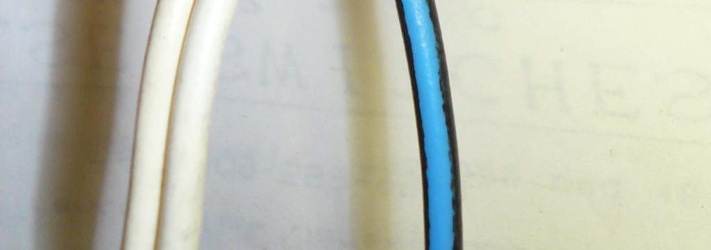
![[Image 5] Do not substitute the silicon RTV](/docs-images/89/99946128/images/5-4.jpg "with other mounting schemes including")
5 Make sure the Turn Signal LED Array is oriented properly. This can be determined by the arrow. The arrow should point outward from center of car body. [Image 4] Retain the LED Array with Blue Silicon RTV, apply in the 4 corners where the LED array contacts the metal reflector. [Image 5] Do not substitute the silicon RTV with other mounting schemes including conductive tape which can damage the electronics. Pantera Electronics Rev. 09/


6 The original ground lug and LED array BLACK wires with lug. [Image 6] Note: You will need to make an extension wire for the WHITE wire. Use a male and female quick disconnect for the extension. [Image 7] Ground wire from chassis installed with nut, replace lamp housing in Pantera with (2) 6mm nuts. [Image 8] Connect the male quick disconnect connectors to match the wire colors in the Pantera wire harness. [Image 9] 6 Pantera Electronics Rev. 09/062014
 look for a metal box suspended above the passenger s")


7 Note: If both front signal and taillights are LED conversions then a flasher designed for LED lights is necessary. Replacing 3 Terminal Turn Signal Flashers Locate the signal flasher in the Pantera, 1971/1972 (Pre-L) look for a metal box suspended above the passenger s side floor. Unscrew the wing nut and lower the metal box look for the signal flasher behind a door in a compartment next to the drivers side door. The original factory signal flasher is a rectangular black box about 2 inches (51 mm) long, it plugs into a socket with 3 wires, BLACK, YELLOW and PINK. Remove by unplugging the signal flasher, the socket will stay mounted on the plate. Connect the Pantera Electronics signal flasher by plugging it into the socket. Replace the metal box and tighten the wing nut. There are 2 adjustments for the flasher, one is the flash rate, one is for selecting the tone. Rotate the black round disk clockwise to increase flash rate, counter clockwise to decrease flash rate. Note the scrolling LED turn signals were designed for 60 flashes per minute flasher setting. There is a 60 labeled on the flasher, set the pointer on the black disk to 60. Make sure the last LED in the array illuminates before the flasher turns OFF. Adjust the rate until all LED s in the array illuminate. To select the flasher sound, position the jumper plug on the 2 pins near the label TONE or the jumper plug to the 2 pins labeled TICK. [Image 10] Factory 3 terminal flasher mounted in a 1971 or 1972 Pantera. Pantera Electronics Rev. 09/


8 Taillight Connector Wire Color Reference Wire Harness Side Flats for orientation. Index for mating connector. Taillight Connector Wire Color Reference Taillight Side Index for mating connector. 8 Pantera Electronics Rev. 09/062014


9 Taillight Connector Wire Color Reference Taillight Side Pantera Electronics Rev. 09/
 look")


 Replace the metal box and tighten the wing nut.")
10 Pantera Electronics 4 terminal turn signal flasher Replacing 4 Terminal Turn Signal Flashers Locate the signal flasher in the Pantera, 1971/1972 (Pre-L) look for a metal box suspended above the passenger s side floor. Unscrew the wing nut and lower the metal box look for the signal flasher behind a door in a compartment next to the drivers side door. The original factory signal flasher is a rectangular black box with 4 wires, BLACK, YELLOW, PINK and ORANGE. Remove each wire individually and connect to the Adjustable Flasher matching to the color labels. The ORANGE wire from the Pantera harness will connect to the ORNG terminal from the Adjustable Flasher. (KBL) Replace the metal box and tighten the wing nut. Factory 4 terminal flasher mounted in a 1971 or 1972 Pantera. Sound select in the TONE position. Adjustment for flash rate. Black wire (GND) Yellow wire (+) Pink wire (LOAD) KBL (Dash Light) (Only AF-02) Image Pantera Electronics Rev. 09/062014

11 Turn Signal Adapter (only needed with 3 terminal flashers) The turn signal adapter is only required if all incandescent lamps, front and back are replaced with LED arrays. Behind the dash, at the bottom of the tachometer housing is the turn signal indicator, connected with 2 orange wires. Remove the lamp socket by pulling the socket straight back. Unplug the 2 orange wires from the lamp socket and plug the 2 female quick disconnect terminals from the Indicator Adapter on the lamp socket. Plug the 2 male quick disconnect terminals from the Indicator Adapter to the 2 orange wires. The black wire with the quick disconnect terminal from the Indicator Adapter is connected the ground connection on the back of the tachometer where other black wires can be found. Adapter for turn signal light, connects to the orange wires from light. Add black wire from light to ground. (tach case) [Image 10] Connect to ground. 2 Orange wires Black ground Disclaimer The products from Pantera Electronics have been designed and manufactured with the best quality components known to the engineer. The installation instructions have been written to assist the owner in the proper use and installation of the products. Pantera Electronics can not be held responsible or held liable for the interpretation or incorrect implementation of the products. Pantera Electronics Rev. 09/

12 Front Harness to Rear Harness Connector Wire Color Reference Front Harness Rear Harness Rear Harness Connector Function Reference Reverse light switch Turn signal light Turn signal light Brake light Running light Running light Condenser Fan 12 Pantera Electronics Rev. 09/062014
Pantera Electronics LED Taillight Conversion Installation Manual
 Pantera Electronics LED Taillight Conversion Installation Manual This LED signal lamp conversion was designed to replace the incandescent lamp 1157 with a Light Emitting Diode Array designed specifically
Installation Manual for the Pantera Ignition Switch Bypass
 Installation Manual for the Pantera Ignition Switch Bypass This Ignition Switch Bypass solves the Pantera owners problem of replacing the ignition switch that is expensive and difficult to source. The
Pantera Electronics Radiator Fan Controller Installation Manual
 Pantera Electronics Radiator Fan Controller Installation Manual IMPORTANT: Radiator Fan Controller Theory It is necessary to understand the theory of the Radiator Fan Controller (RFC will be used throughout
CHEVORLET IMPALA
 1962-64 CHEVORLET IMPALA Four Panel Sequential LED Tail Light Kit Installation Guide Kit Contents: 4 LED panels 1 deck lid harness 4 grommets 1 power wire 2 pigtail harness kits 2 crimp terminal kits PN
Pantera Electronics LED Gauge Lamp Installation Manual
 Pantera Electronics LED Gauge Lamp Installation Manual This installation manual is to assist in the installation of Pantera-Electronics LED Gauge Lamp. The LED Gauge Lamp will only operate when installed
EU DLX LED Tail-Light Kit Installation:
 WWW.MUSTANGPROJECT.COM Page 1 1964.5-1966 EU DLX LED Tail-Light Kit Installation: First we will remove the old original flasher module. The original flasher module will be located on the driver side of
CHEVY CAMARO Four panel Sequential LED Taillight kit installation guide
 1978-81 CHEVY CAMARO Four panel Sequential LED Taillight kit installation guide Kit Contents: 4 LED panels 1 power wire with t-tap 2 driver side LED harnesses, 24 2 passenger side LED harnesses, 48 4 LED
PONTIAC FIREBIRD
 1974-78 PONTIAC FIREBIRD Two Panel Sequential LED Tail Light Kit Installation Guide Kit Contents: 2 LED panels 2 LED panel mount kits 6 rubber grommets 1 power wire 1 pigtail harness Kit 1 crimp terminal
Brake and Tail Light Kit Workman 1100/2100 and Twister Utility Vehicles
 Form No. 5-90 Brake and Tail Light Kit Workman 00/00 and Twister Utility Vehicles Part No. 0 6697 Installation Instructions Important Before installing this kit, you must have Wiring kit number 99 79 installed
PN R CHEVY CAMARO w/reverse Two panel Sequential LED Taillight kit installation guide. Kit Contents:
 Two panel Sequential LED Taillight kit installation guide Kit Contents: 2 LED panels 4 rubber grommets 1 power wire with t-tap 1 driver side LED harness, 24 1 passenger side LED harness, 48 2 LED extension
Sequential Tail Light System
 Sequential Tail Light System Installation Instructions Notice: Our conversion systems are intended for 1965-70 Ford Mustangs only. This is not a replacement system for Shelby Mustangs or Mercury Cougars
2-row and All-row systems included.
 Ag Leader Technology Cotton Picker Installation Installation Instructions for John Deere cotton picker models: 2-row and All-row systems included. IMPORTANT: Ensure the model numbers shown above correspond
Installation Instructions
 Installation Instructions These instructions cover the following kits: 64-66 Mustang Sequential Turn Signal LED kit 67-68 Mustang Sequential Turn Signal LED kit Kit Contents 2 x LED Tail Light Panels 2
Dash Procedure (Dash Cluster Corvette) for color upgrade
 for color upgrade") Dash Procedure (Dash Cluster 1984-1989 Corvette) for color upgrade Chapter 1 Please read all instructions before proceeding. 1. Disconnect negative battery cable. 2. Use small flat blade screw driver to
Dash Procedure (Dash Cluster 1984-1989 Corvette) for color upgrade Chapter 1 Please read all instructions before proceeding. 1. Disconnect negative battery cable. 2. Use small flat blade screw driver to
2005 and 09 Mustang install instructions Sequential / Chase Unit Partial Plug-N-Play Kit Meter4it Eng. Updated: 3/28/09
 Updated: 3/28/09 Verify content of kit: 1- Unit with wiring harness 1- Red power wire with 15 amp fuse 1- Color instruction 2- Velcro for mounting 1-Driver taillight harness 1- Passenger taillight harness
PN PONTIAC FIREBIRD. Kit Contents: Four Panel Sequential LED Tail Light Kit Installation Guide
 1969 PONTIAC FIREBIRD Four Panel Sequential LED Tail Light Kit Installation Guide Kit Contents: 4 LED panels 4 rubber grommets 1 power wire 2 pigtail harness kits 2 crimp terminal kits PN 1100569 1969
Components included in your kit:
 Page 1 Components included in your kit: All of the equipment illustrated in this manual was proudly manufactured in the USA by Mustang Project a SafeCode Inc. enterprise. For accessories and spare parts
Components included in your kit:
 Page 1 Components included in your kit: The LED flasher module will replace your existing flasher module. The left and right taillight modules will replace your existing All of the equipment illustrated
ELECTRICAL DIAGNOSTICS & OPERATION
 Operation Function: Provides power to the headlights, tail lights, hazard lights, work light and dash lights in different combinations depending upon the position the light switch is placed in. Operating
UNIVERSAL GAUGE WIRE HARNESS
 2650-1797-00 UNIVERSAL GAUGE WIRE HARNESS For Installing Auto Meter Electric Speedometer, Tachometer, And Short Sweep Electric Oil Pressure, Water Temperature, Fuel Level, and Volt Meter Gauges. This harness
Detroit Speed, Inc. Electric Headlight Door Kit Corvette P/N: &
 Detroit Speed, Inc. Electric Headlight Door Kit 1968-82 Corvette P/N: 122006 & 122007 The Detroit Speed Inc. Electric Headlight Door Kit replaces the stock vacuum actuated system on all 1968-82 Corvettes.
UNPACK AND IDENTIFY THE FOLLOWING PARTS.
 SUT-250-M2 ASSEMBLY REQUIREMENTS *Torque all T-bolt nuts to 35-40 foot pounds. *Check all lights before towing. *Tire pressure not to exceed recommendation on serial tag. *Re-torque wheel nuts after first
MAVERICK, PINTO. Two Panel Sequential LED Tail Light Kit Installation Guide
 1970-77 MAVERICK, 71-76 PINTO Two Panel Sequential LED Tail Light Kit Installation Guide Kit Contents: 2 LED panels 2 rubber grommets 1 power wire with t-tap 1 driver side LED harness, 24 1 passenger side
Custom Dynamics LED Tri-Bar Fender Tip Installation Instructions
 Custom Dynamics LED Tri-Bar Fender Tip Installation Instructions We thank you for purchasing the Custom Dynamics LED Tri-Bar Fender Tip! Our products utilize the latest technology and high quality components
Camaro Camaro
 Important facts about this kit. 1. The dash panel used in this picture is used by permission of Covan's Classic. We Make Wiring Easy! 2. This kit requires some modification to your original under dash
ClassicLEDs LLC. Sequential LED System
 ClassicLEDs LLC 1967 and 1968 Mustang Sequential LED System CLE30015S Thank you for your purchase. This is the latest design of our 1967 and 1968 Mustang sequential LED system. There have been several
INSTALLATION INSTRUCTIONS TRAILER HITCH MAIN HARNESS KIT
 PART NUMBER: 0000-89-N30 GENUINE ACCESSORIES INSTALLATION INSTRUCTIONS TRAILER HITCH MAIN HARNESS KIT APPLICABLE MODELS: 2016 > CX-9 PACKAGE CONTENTS: INSTALLATION INSTRUCTIONS QTY 1 CABLE TIE MOUNT QTY
Pontiac GTO with Factory Air Control Panel Conversion Kit (473167)
") an ISO 900:008 Registered Company 964-67 Pontiac GTO with Factory Air Control Panel Conversion Kit (4767) DE-ICE HEAT OFF VENT OUT INSIDE 8865 Goll St. San Antonio, TX 7866 Phone: 0-654-77 Fax: 0-654-
an ISO 900:008 Registered Company 964-67 Pontiac GTO with Factory Air Control Panel Conversion Kit (4767) DE-ICE HEAT OFF VENT OUT INSIDE 8865 Goll St. San Antonio, TX 7866 Phone: 0-654-77 Fax: 0-654-
CHEVY MONTE CARLO. Two Panel Sequential LED Tail Light Kit Installation Guide
 1986-88 CHEVY MONTE CARLO Two Panel Sequential LED Tail Light Kit Installation Guide Kit Contents: 2 LED panels 4 rubber grommets 1 power wire 1 pigtail harness Kit 1 crimp terminal Kit 1 adhesive tube
INSTRUCTIONS. 20 Circuit Wiring Kit Instructions October 2009, Speedway Motors, Inc.
 1 MAIN FUSE PANEL The main fuse panel harness s designed to be mounted under the dash a the firewall in an area close to the steering column. The enclosed representation of the main dash harness shows
ATTENTION. Custom Dynamics Smart Triple Play Installation Instructions. Package Contents: - Smart Triple Play Module (1) - Instructions
 - Instructions") Custom Dynamics Smart Triple Play Installation Instructions We thank you for purchasing the Custom Dynamics Smart Triple Play. Our products utilize the latest technology and high quality components to
Custom Dynamics Smart Triple Play Installation Instructions We thank you for purchasing the Custom Dynamics Smart Triple Play. Our products utilize the latest technology and high quality components to
CLASSIC UPDATE WIRING KIT
 by Randy Irwin 1955-57 CLASSIC UPDATE WIRING KIT Randy Irwin - Technical Writer Randy has been involved in the Chevy parts business for over 25 years. He is a wizard at creating, making and modifying custom
PN CHEVY TRI-FIVE. Kit Contents: Four panel Sequential LED Taillight kit installation guide
 Four panel Sequential LED Taillight kit installation guide Kit Contents: 2 tail light LED panels 2 tail light turn signal LED panels 1 rubber boot/sleeve kit 1 power wire with t-tap 1 driver side LED harness,
MUSTANG PROJECT INSTALLING THE MUSTANG PROJECT SHELBY SEQUENTIAL CONVERSION KIT ON YOUR MUSTANG
 VOLUME 6 Price:$9.95 MUSTANG PROJECT A SafeCode Inc. Publication INSTALLING THE MUSTANG PROJECT SHELBY SEQUENTIAL CONVERSION KIT ON YOUR 64.5-66 MUSTANG Convert from original 1964.5-66 Mustang style taillights
LGT-306L / LB Club Car Precedent LED Light Bar Bumper Kit Installation Instructions
 LGT-306L / LB Club Car Precedent LED Light Bar Bumper Kit Installation Instructions Caution: Please read through the instructions carefully. Before starting this project, remove the system s positive and
Detroit Speed, Inc. Electric Headlight Door Kit Corvette P/N: &
 Detroit Speed, Inc. Electric Headlight Door Kit 1968-82 Corvette P/N: 122006 & 122007 The Detroit Speed Inc. Electric Headlight Door Kit replaces the stock vacuum actuated system on all 1968-82 Corvettes.
Replace light bulb with the same number bulb as the one removed. White Wire: Connect to +12 Volt Lighting
 INSTALLATION INSTRUCTIONS SHORT SWEEP ELECTRIC GAUGES 2650-1079-00 Rev. C CAUTION FOR ALL GAUGE INSTALLATION (AMMETERS EXCLUDED) As a safety precaution, the +12V wire attached to the positive I (+) terminal
Dash removal for 1968 Chevelles
 Dash removal for 1968 Chevelles This is the procedure I used when I removed the dash from my car. It s a column shift, automatic trans, A/C car with tach and gauges. 1. Disconnect the battery. 2. Remove
CHEVY NOVA w/reverse Four Panel Sequential LED Taillight Kit Installation Guide
 1970-72 CHEVY NOVA w/reverse Four Panel Sequential LED Taillight Kit Installation Guide Kit Contents: 4 LED panels 4 rubber grommets 1 power wire with t-tap 1 driver side LED harness, 24 (5 pin) 1 passenger
jegs.com
 Contents Wiring Harness w/ Fuse Panel Installation Instructions Turn Signal Plug w/ Terminals 2 Headlight Plugs 3/4 Grommet 10 ¼ Terminals 4 Ring Terminals 10 Wire Ties Fusible Link 2 Screws & Nuts 2 Plastic
1956 Ford Passenger Car Control Panel Conversion Kit (473150)
") an ISO 900:2008 Registered Company 956 Ford Passenger Car Control Panel Conversion Kit (47350) 8865 Goll St. San Antonio, TX 78266 Phone: 20-654-77 Fax: 20-654-33 www.vintageair.com 900505 REV B 04/4/5,
an ISO 900:2008 Registered Company 956 Ford Passenger Car Control Panel Conversion Kit (47350) 8865 Goll St. San Antonio, TX 78266 Phone: 20-654-77 Fax: 20-654-33 www.vintageair.com 900505 REV B 04/4/5,
JOHN DEERE GATOR SWITCH PANEL INSTRUCTIONS FITS 1GTRXUV2 AND 1GTRXUV4 CABS (p/n: 1XUVSP)
") P. 1 of 5 JOHN DEERE GATOR SWITCH PANEL INSTRUCTIONS FITS 1GTRXUV2 AND 1GTRXUV4 CABS (p/n: 1XUVSP) Note: Harness Extension Kit Required for 4 Passenger (p/n: 1XUV4WHEK) This manual is the property of the
P. 1 of 5 JOHN DEERE GATOR SWITCH PANEL INSTRUCTIONS FITS 1GTRXUV2 AND 1GTRXUV4 CABS (p/n: 1XUVSP) Note: Harness Extension Kit Required for 4 Passenger (p/n: 1XUV4WHEK) This manual is the property of the
Replace light bulb with the same number bulb as the one removed. White Wire: Connect to +12 Volt Lighting
 INSTALLATION INSTRUCTIONS SHORT SWEEP ELECTRIC GAUGES 2650-1079-00 Rev. C CAUTION FOR ALL GAUGE INSTALLATION (AMMETERS EXCLUDED) As a safety precaution, the +12V wire attached to the positive I (+) terminal
PONTIAC FIREBIRD. Four Panel Sequential LED Tail Light Kit Installation Guide
 1967-68 PONTIAC FIREBIRD Four Panel Sequential LED Tail Light Kit Installation Guide Kit Contents: 4 LED panels 4 rubber grommets 1 power wire 2 pigtail harness kits 2 crimp terminal kits PN 1100567 Please
SP Switch Programmable Switch Panel Power System. Parts Included
 SP8100 8-Switch Programmable Switch Panel Power System Parts Included 1 Switch Panel 1 100 amp Power Module 1 Power Module Harness 1 Power Module Mounting Plate 1 Battery Cable w/100a MIDI fuse (Littlefuse
8436, 8437, 8438, 8439, 8442, 27480, 27780, 28028, & ISOLATION MODULE ELECTRICAL SYSTEM
 September 11, 2003 Lit. No. 27808 8436, 8437, 8438, 8439, 8442, 27480, 27780, 28028, & 28400 ISOLATION MODULE ELECTRICAL SYSTEM Installation Instructions Read this document before installing the snowplow.
Detroit Speed, Inc. Selecta-Speed Wiper Kit Corvette P/N:
 Detroit Speed, Inc. Selecta-Speed Wiper Kit 1968-72 Corvette P/N: 121621 A downpour of rain will no longer hinder your ability to clearly see the road. The Detroit Speed Selecta-Speed Wiper Kit provides
DASH/MAIN HARNESS. NOTE: wires 400 & 401, must be twisted together.
 Electric Speedo Ground 151 Turn Flasher 16A 4 150 8A, Cluster Connections 31 33 30 35 151 (electric speedo) 402 401 NOTE: wires 400 & 401, must be twisted together. 156D, E Panel Dimmer 8A 9, C 2D Headlight
FORD MUSTANG. Two Panel Sequential LED Tail Light Kit Installation Guide
 1967-68 FORD MUSTANG Two Panel Sequential LED Tail Light Kit Installation Guide Kit Contents: 2 LED panels 2 rubber grommets 1 power wire with t-tap 1 driver side LED harness, 24 1 passenger side LED harness,
UNPACK AND IDENTIFY THE FOLLOWING PARTS.
 SUT-500-S ASSEMBLY REQUIREMENTS *Torque all T-bolt nuts to 35-40 foot pounds. *Check all lights before towing. *Tire pressure not to exceed recommendation on serial tag. *Re-torque wheel nuts after first
Ford Mustang with Factory Air Control Panel Conversion Kit (475170)
") an ISO 900:205 Registered Company 969-70 Ford Mustang with Factory Air Control Panel Conversion Kit (47570) 8865 Goll St. San Antonio, TX 78266 Phone: 800-862-6658 Sales: sales@vintageair.com Tech Support:
an ISO 900:205 Registered Company 969-70 Ford Mustang with Factory Air Control Panel Conversion Kit (47570) 8865 Goll St. San Antonio, TX 78266 Phone: 800-862-6658 Sales: sales@vintageair.com Tech Support:
Instructions for 2-row monitoring only
 Installation Instructions for CaseIH cotton picker models: Instructions for 2-row monitoring only Ensure the model numbers shown above correspond to the machine model. If you receive the incorrect installation
C50254A PH3 AIR INTAKE SHUT-OFF VALVE DODGE 6.7L CUMMINS WITH POWERGUARD SMART OVERSPEED LIMITER
 AIR INTAKE EMERGENCY SHUT-OFF VALVE C50254A PH3 AIR INTAKE SHUT-OFF VALVE WITH POWERGUARD SMART OVERSPEED LIMITER 2013-2017 DODGE 6.7L CUMMINS www.powerhalt.com INSTALLATION REQUIREMENTS & RECOMMENDATIONS:
PN DODGE CORONET Two panel Sequential LED Taillight kit installation guide. Kit Contents:
 1969 DODGE CORONET Two panel Sequential LED Taillight kit installation guide Kit Contents: 2 LED panels 4 rubber grommets 1 power wire with t-tap 1 driver side LED harness, 24 1 passenger side LED harness,
Installation Manual TWM Performance Short Shifter Cobalt SS/SC, SS/TC, HHR SS, Ion Redline and Saab 9-3
 Page 1 Installation Manual TWM Performance Short Shifter Cobalt SS/SC, SS/TC, HHR SS, Ion Redline and Saab 9-3 Please Note: It is preferable to park on a flat surface, as you will have to engage and disengage
Pantera Electronics Rocker Switch Installation Manual
 Pantera Electronics Rocker Switch Installation Manual Finishing the Bezel PRELIMINARY [to achieve a anodized appearance with paint] 1. Remove the 4 screws and nylon washers that retain the housing to the
Installation Instructions for John Deere cotton picker models: 9986 & 2-row and All-row systems included.
 Ag Leader Technology Cotton Picker Installation Installation Instructions for John Deere cotton picker models: 9986 & 9996 2-row and All-row systems included. IMPORTANT: Ensure the model numbers shown
Classic Update Series
 Classic Update Series *** These are special for connecting your wiring system to a stock instrument cluster. *** (Note: This kit does not support the use of a stock ammeter.) REFER TO THE TTCHED DIGRMS
29048, 29049, 29050, 29051, 29052, 29053, 29054,
 April 15, 2014 Lit. No. 29225, Rev. 11 29048, 29049, 29050, 29051, 29052, 29053, 29054, 29400 5 HARNESS KIT 3 PORT ISOLATION MODULE LIGHT SYSTEM w/2 PLUG SYSTEM HARNESSES Installation Instructions Read
Installing the STS-4CH Dodge Challenger Sequential Turn Signal System
 Installing the STS-4CH 2008-2010 Dodge Challenger Sequential Turn Signal System The STS-4CH is an exciting addition to your 2008-2010 Dodge Challenger. This Plug-N-Play system comes complete with pre-wired
SUT-250-S (These instructions are used for SUT-250-SCLC also)
") SUT-250-S (These instructions are used for SUT-250-SCLC also) Torque wrench, carpenters square, wire cutters, Phillips screwdriver, 7/16, 9/16, and 3/4 combination wrenches, ratchet, 9/16, 3/4, 13/16,
SUT-250-S (These instructions are used for SUT-250-SCLC also) Torque wrench, carpenters square, wire cutters, Phillips screwdriver, 7/16, 9/16, and 3/4 combination wrenches, ratchet, 9/16, 3/4, 13/16,
Turn Signal / Horn Kit PN 7101 by All years Polaris RZR 1000 and RZR 900, 900-4, 900 trail, 900S and 900XC STOP - THIS KIT IS DESIGNED
 All years Polaris RZR 1000 and 1000-4 2015 RZR 900, 900-4, 900 trail, 900S and 900XC STOP - THIS KIT IS DESIGNED SPECIFICALLY FOR ALL YEAR AND MODEL POLARIS RZR 1000 AND 1000-4. ALSO THE 2015 POLARIS RZR
wiring instructions NEW FORD WIRE MOD 60 INCH BLADE INCH BLADE
 wiring instructions 2018-2019 + NEW FORD WIRE MOD New technologically advanced logic box solves and eliminates all codes from trailering, backup assist, BLIS (Blind Spot Information System) and all currently
Four Panel Sequential LED Tail Light Kit Installation Guide
 1969 CHEVY CAMARO Four Panel Sequential LED Tail Light Kit Installation Guide Kit Contents: 4 LED panels 4 rubber grommets 1 power wire with t-tap 2 driver side LED harnesses, 24 2 passenger side LED harnesses,
29048, 29049, 29050, 29051, 29052, 20953, 29054,
 July 15, 2008 Lit. No. 29225, Rev. 06 29048, 29049, 29050, 29051, 29052, 20953, 29054, 29400-2 HARNESS KIT 3-PORT ISOLATION MODULE LIGHT SYSTEM w/2-plug SYSTEM HARNESSES Installation Instructions Read
TOYOTA YARIS KEYLESS ENTRY SYSTEM
 TOYOTA YARIS 2011 - KEYLESS ENTRY SYSTEM Part Number: 00016-32901 Accessory Code: KE1 Conflicts Not for installation in vehicles equipped with factory installed keyless entry. Kit Contents Item # Quantity
1968 PLYMOUTH ROAD RUNNER
 Sequential LED Tail Light Kit Installation Guide 1968 PLYMOUTH ROAD RUNNER PN 1200568 Please refer to Invoice for full warranty information DIGI-TAILS is not a licensed MOPAR product Note The LED boards
Light Kit Groundsmaster 7200 Series Mowers
 Form No. 3405-333 Rev A Light Kit Groundsmaster 7200 Series Mowers Model No. 31508 Serial No. 400000000 and Up Register at www.toro.com. Original Instructions (EN) *3405-333* A Ordering Replacement Parts
Instructions for 2-row monitoring only
 Installation Instructions for CaseIH cotton picker models: Instructions for 2-row monitoring only CAUTION: Ensure the model numbers shown above correspond to the machine model. If you receive the incorrect
Plus SABRE LIGHTBARS
 INSTALLATION AND INSTRUCTION MANUAL Plus SABRE LIGHTBARS Models 5364LED, 5462LED, 5464LED and 5564LED PLIT445 REV. D 2/2/18 Keep any radio frequency sensitive equipment at least 20 from the bar and power
INSTRUCTION SHEET FOR SIGNALMASTER MODELS SM518A AND SM428A
 2561263C REV. C 407 Printed in U.S.A. INSTRUCTION SHEET FOR SIGNALMASTER MODELS SM518A AND SM428A SAFETY MESSAGE TO INSTALLERS People s lives depend on your safe installation of our products. It is important
2010 Toyota Prius Fog Light Retrofit
 2010 Toyota Prius Fog Light Retrofit A DIY prospective Last updated: Friday, December 25, 2009 *** Disclaimer Use this document and its contents at your own risk! *** Forward: This document was compiled
SECTION ELECTRICAL SYSTEM
 6-0.0/ BATTERIES 8D 004AL SECTION 6-000.04 ELECTRICAL CIRCUITS CAUTION: Nova LFS buses are equipped with a negativeground electrical circuit. DO NOT inverse the polarities while using an auxiliary battery
System III Wiring Information 54-12
 System III Wiring Information 54-12 System Operation General Information Initial Power On Description of Revisions: This service bulletin is updated and replaces the version dated September 2002. This
1963 Chevrolet Impala Control Panel Conversion Kit (471063)
") an ISO 9001:2008 Registered Company 196 Chevrolet Impala Control Panel Conversion Kit (47106) 18865 Goll St. San Antonio, TX 78266 Phone: 210-654-7171 Fax: 210-654-11 www.vintageair.com 901065 REV E 01/12/16,
an ISO 9001:2008 Registered Company 196 Chevrolet Impala Control Panel Conversion Kit (47106) 18865 Goll St. San Antonio, TX 78266 Phone: 210-654-7171 Fax: 210-654-11 www.vintageair.com 901065 REV E 01/12/16,
Lighting GENERAL INFORMATION. Daytime running lamps. Condensation. Stop lamps. Halogen headlamps. Reversing lamps. Bi-Xenon headlamps
 Lighting GENERAL INFORMATION There are three types of headlamp systems: Halogen high/low beam main lamp with a fill-in high beam halogen lamp alongside. Bi-xenon high/low beam main lamps with fill-in high
Classic Update Series
 Classic Update Series *** These are special for connecting your wiring system to a stock instrument cluster. *** (Note: This kit does not support the use of a stock ammeter.) REFER TO THE TTCHED DIGRMS
PH2 POWERHALT AIR INTAKE SHUT-OFF VALVE C50201A ½ DODGE 6.7L CUMMINS C50202A DODGE 6.
 PH2 POWERHALT AIR INTAKE SHUT-OFF VALVE WITH POWERGUARD SMART OVERSPEED LIMITER C50201A - 2007½ - 2009 DODGE 6.7L CUMMINS C50202A - 2010-2012 DODGE 6.7L CUMMINS www.powerhalt.com Thank you for your purchase
ML63AMG appartiens à un membre de mbworld.org merci. W210 E Class Folding Mirror Modification
 ML63AMG appartiens à un membre de mbworld.org merci W210 E Class Folding Mirror Modification Originally installed in 2002. Revised write up completed September 5, 2013. Step 1 - New Switch and Wiring Harness
Thank you for purchasing the Craven Speed FlexPod Complete Gauge Pod Kit
 Thank you for purchasing the Craven Speed FlexPod Complete Gauge Pod Kit Before You Start Please read instructions completely before installing. These instructions contain the information required to install
Installation instruction do88 Intercooler for SAAB 9-3 1,9 TTiD
 Installation instruction do88 Intercooler for SAAB 9-3 1,9 TTiD This instruction shows how to replace the OEM intercooler with this performance intercooler. At this type of installation we always recommend
Validator and Control Board Update Instructions for BC1
 Validator and Control Board Update Instructions for BC1 Installation Overview The update kit for the Rowe BC1 enables the changer to interface with a Mars AE/VN 120-volt validator. The validator determines
Universal. 362 For RoadWorks customer service, call LIGHTS Bullet Plugs! With
 Universal LIGHTS A. 2 ROUND LIGHTS LED with a single diode. Uses standard double plug harness. (Each) Amber 08005 Red 08006 08005C 08006C B. 2 ROUND BEEHIVE LIGHTS LED with 10 diodes. Uses standard double
Installation Manual TWM Performance Short Shifter 2008 Mitsubishi Lancer
 Page 1 Installation Manual TWM Performance Short Shifter 2008 Mitsubishi Lancer Please Note: It is preferable to park on a flat surface, as you will have to engage and disengage the hand brake and shift
DeSoto NEMA 4X EMERGENCY LIGHTING UNIT. U.S. Versions: 6V- DM90X618 / DM90X654 12V- DM90X1254 / DM90X12100 INSTALLATION INSTRUCTIONS
 DeSoto U.S. Versions: 6V- DM90X618 / DM90X654 12V- DM90X1254 / DM90X12100 NEMA 4X EMERGENCY LIGHTING UNIT INSTALLATION INSTRUCTIONS U.S. Patent No.s 6,135,624; 6,193,395; 6,502,044 B1; D505,222; IMPORTANT
Chevrolet Full-Size 3-Lever Control Panel Conversion Kit (473059)
") an ISO 900:2008 Registered Company 955-56 Chevrolet Full-Size -Lever Control Panel Conversion Kit (47059) 8865 Goll St. San Antonio, TX 78266 Phone: 800-862-6658 Sales: sales@vintageair.com Tech Support:
an ISO 900:2008 Registered Company 955-56 Chevrolet Full-Size -Lever Control Panel Conversion Kit (47059) 8865 Goll St. San Antonio, TX 78266 Phone: 800-862-6658 Sales: sales@vintageair.com Tech Support:
1969 Chevrolet Camaro with Factory Air Control Panel Conversion Kit (474269)
") an ISO 900:2008 Registered Company 969 Chevrolet Camaro with Factory Air Control Panel Conversion Kit (474269) 8865 Goll St. San Antonio, TX 78266 Phone: 20-654-77 Fax: 20-654-33 www.vintageair.com 904269
an ISO 900:2008 Registered Company 969 Chevrolet Camaro with Factory Air Control Panel Conversion Kit (474269) 8865 Goll St. San Antonio, TX 78266 Phone: 20-654-77 Fax: 20-654-33 www.vintageair.com 904269
Headlight Switch Connector. Brake Switch. Lead Wires. Main Power Feed from Starter. Fuse Box Connections (viewed from underside)
") 0 Heller Pl #17 W ellmawr, NJ 0031 6-933-001 TH KT DOE NOT UPPORT TOCK (ORGNL) GENERTOR. THE DEGN OF THE KT DEGNED TO UPPLY MORE POWER THN THE GENERTOR LE TO UPPLY. 16 6 4D 4C 4D 0 0 0 4C 4 4 43 7 39 3
0 Heller Pl #17 W ellmawr, NJ 0031 6-933-001 TH KT DOE NOT UPPORT TOCK (ORGNL) GENERTOR. THE DEGN OF THE KT DEGNED TO UPPLY MORE POWER THN THE GENERTOR LE TO UPPLY. 16 6 4D 4C 4D 0 0 0 4C 4 4 43 7 39 3
WIRING HARNESS KIT ELECTRONIC FLASHERS
 356 WIRING HARNESS KIT Part No. 1546103 Universal Wiring 48 Harness For Lowboys, Flats, and Logging Trailers Comes complete with ABS power cord connector, ABS warning light pigtail, metal 7-way plug, front
Part Number Analog EGT Gauge
 Part Number 30-5131 Analog EGT Gauge Figure 1. Wiring Schematic AEM EGT Gauge Parts 1 x 35-5131(B/W) EGT Gauge Assembly 1 x 30-2065 EGT Sensor Thermocouple w/mount 1 x 35-4302 Install Kit (6 Butt Connectors)
TRAILER CONNECTORS CONNECTEURS POUR REMORQUES CONECTORES PARA TRAILERS Y REMOLQUES. 10 Trailer Sockets. 11 Nose Boxes & Socket Breakers
 02 10 Trailer Sockets 11 Nose Boxes & Socket Breakers 12 Trailer Plugs 16 Junction Boxes 16 Corrosion Preventive Sealant TRAILER CONNECTORS CONNECTEURS POUR REMORQUES CONECTORES PARA TRAILERS Y REMOLQUES
Headlight Switch Connector. Brake Switch. Lead Wires. Main Power Feed from Starter. Fuse Box Connections (viewed from underside)
") www.americanautowire.com 86-933-0801 TH KT DOE NOT UPPORT TOCK (ORGNAL) GENERATOR. THE DEGN OF THE KT DEGNED TO UPPLY MORE POWER THAN THE GENERATOR ALE TO UPPLY. 16 68A 4D 4C 4D 0 0 0 4C 4 43 7 39 3 Dimmer
www.americanautowire.com 86-933-0801 TH KT DOE NOT UPPORT TOCK (ORGNAL) GENERATOR. THE DEGN OF THE KT DEGNED TO UPPLY MORE POWER THAN THE GENERATOR ALE TO UPPLY. 16 68A 4D 4C 4D 0 0 0 4C 4 43 7 39 3 Dimmer
INSTALLATION MANUAL SPECTRUM BRAKE CONTROL
 INSTALLATION MANUAL 51170 SPECTRUM BRAKE CONTROL TABLE OF CONTENTS Controls & Components Tools List Before You Begin Wiring Wiring Diagram Mounting the LED Display Rotary Knob Wiring the Plug Connector
Turn Signal Kit Installation Instructions for Model A Fords & Other Antique Vehicles
 Turn Signal Kit Installation Instructions for Model A Fords & Other Antique Vehicles Lifetime Technical Support support@logolites.com 770-476-7322 www.logolites.com Manual 100-0005N Thank you for purchasing
SUT-450-I ASSEMBLY REQUIREMENTS
 SUT-450-I Torque wrench, carpenters square, wire cutters, Phillips screwdriver, 7/16, 9/16, and 3/4 combination wrenches, ratchet, 9/16,3/4,13/16, and 7/8 sockets. ASSEMBLY REQUIREMENTS *Torque all T-bolt
Installation Guide. Fits Models: RF-2 Touring Models 2009-Present. Revised 12.15
 Oil Cooler Installation Guide Fits Models: RF-2 Touring Models 2009-Present Revised 12.15 Welcome To UltraCool Oil Cooling Systems Thank you for making UltraCool your oil cooling system of choice. We hope
BUICK SKYLARK/GS
 Sequential LED Tail Light Kit Installation Guide 1970-72 BUICK SKYLARK/GS PN 1101170 Please refer to Invoice for full warranty information DIGI-TAILS is not a licensed GM product Note The LED boards are
MCL-3000 SERIES AIR PRESSURE PART# MCL-3K-A
 MCL-3000 SERIES AIR PRESSURE PART# MCL-3K-A Thank you for purchasing the Dakota Digital MCL-3K-A gauge for your Harley Davidson Touring bike. This gauge is designed to be a direct, plug in replacement
Sure-Lites. Installation Instructions for the Sure-Lites UX Self Powered Exit Sign with Self Diagnostics. IB505037EN Important Safeguards
 049-289 Sure-Lites Installation Instructions for the Sure-Lites UX Self Powered Exit Sign with Self Diagnostics. WARNING Risk of Fire/Electric Shock If not qualified, consult an electrician. WARNING Risk
LEXUS GS 350/450h ILLUMINATED DOOR SILLS Preparation
 Preparation Part Number: PT922-30120 (GS350) PT922-30130 (GS450h) NOTE: Part number of this accessory may not be the same as the part number shown. Kit Contents Item # Quantity Req'd. Description 1 1 Illuminated