WARNING indicates a potentially hazardous situation which, if not avoided, could result in property damage, serious personal injury or even death.
|
|
|
- Roy Roberts
- 5 years ago
- Views:
Transcription


.")

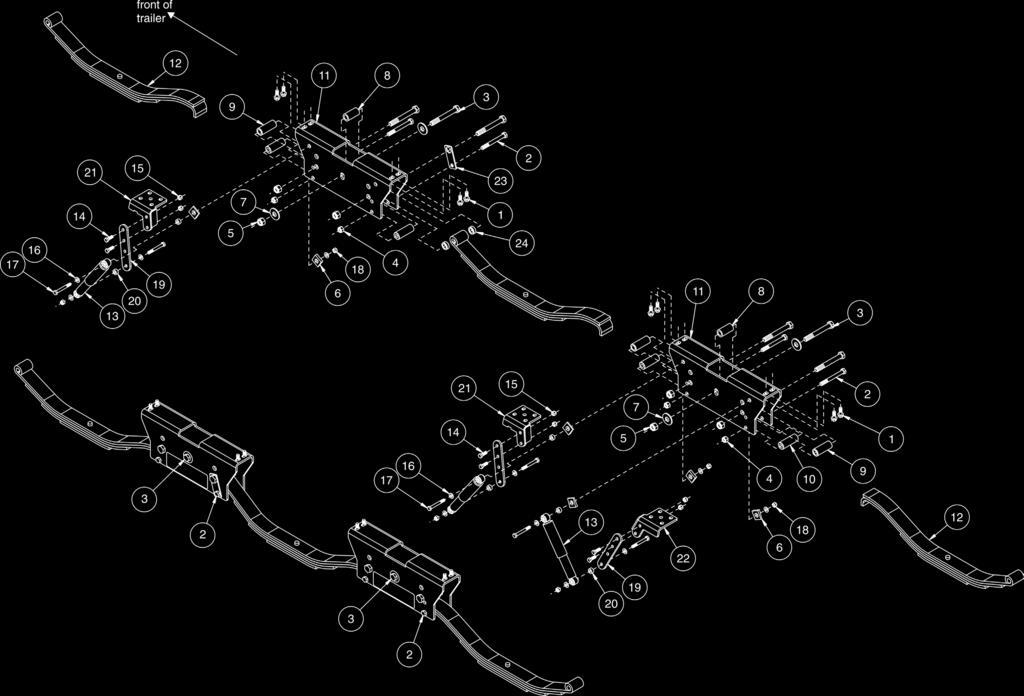
1 Comfort Ride Third axle slipper leaf spring system (part numbers , and ) and shock absorber system (part numbers , and ) Installation Instructions All specifications are subject to change without notice. General warnings and cautions Read all instructions before installing this product. Failure to understand how to install this product could result in property damage, personal injury or even death. Note: If you re a professional installer, please give these instructions to the customer once the kit is installed. Note: For ease of installation, the shock absorbers are shipped with restraining bands to hold them at a specific length. Don t remove the restraining bands until instructed to do so. General hand tools Torque wrench Center punch Required tools 21/64" drill bit Threadlocker ROADMASTER, Inc N.E. 127th Ave. Vancouver, WA Fax roadmasterinc.com ATTENTION This kit is designed to supplement Roadmaster s Comfort Ride slipper leaf spring system for tandem axle trailers (part numbers 2560, 2570 and 2580). The leaf springs are to be used only in conjunction with a Comfort Ride shock absorber system (tandem axle shock absorber kits 2450, 2460, 2470; third axle kits , and ). ATTENTION These instructions will guide you through the installation of the shock system and slipper spring system for all three axles. If installing the system on a triple-axle trailer, do not follow any other set of instructions. Check that you have the correct kit. Kit number is for axles up to and including 6,000-pound capacity; kit number is for 7,000-pound capacity axles, and kit number 2580 is for 8,000-pound capacity axles. If your trailer s axles fall between these weight capacities, use the kit with the closest capacity. Ensure that the U-bolts attaching the trailer s leaf springs to the axles have at least ½" of thread showing beyond the nut (Figure 1). Before you begin the installation Figure 1 Safety Definitions These instructions contain information that is very important to know and understand. This information is provided for safety and to prevent equipment problems. To help recognize this information, observe the following symbols: WARNING indicates a potentially hazardous situation which, if not avoided, could result in property damage, serious personal injury or even death. indicates a potentially hazardous situation which, if not avoided, may result in property damage, or minor or moderate personal injury. Check for any under-vehicle obstructions in and around the trailer s suspension (such as plumbing, wiring or other trailer components) that may prevent the installation of the product. It may be necessary to modify or relocate components in order to install this product. at least ½" used without the safety alert symbol indicates a potentially hazardous situation which, if not avoided, may result in property damage. NOTE Refers to important information and is placed in italic type. It is recommended that you take special notice of these items.
2
3 Slipper spring kit 2560, 2570 or 2580 and components from , or Part Item Qty Number Description /8-16 x 1" grade 8 self-tapping screw /16-14 x 4" grade 5 bolt /16-12 x 4½" grade 8 bolt /16-14 grade 5 nylon insert lock nut /16-12 grade 8 nylon insert lock nut wedge washer /16" grade 8 flat washer A " O.D. x 0.640" I.D. x 2" spacer A " O.D. x 0.640" I.D. x 2.625" roller A ¾" O.D. x.5" I.D. x 2.690" spacer B slipper spring box D and leaf springs 6...D and leaf springs 6...D and leaf springs A anti-rotation lock plate A " O.D. x 0.640" I.D. x 0.375" spacer Shock absorber kit 2450, 2460 or 2470 and components from , or Part Item Qty Number Description shock absorber ½-13 x 1½" grade 5 bolt ½-13 grade 5 nylon insert lock nut M12 flat washer M12 x 1.75 x 100mm bolt class M12 x 1.75 nylon insert lock nut class A extension plate A ½" spacer C tie plate with notch for 2-3/8" axle 2450 and C tie plate with notch for 3" axle 2460 and C tie plate with notch for 3½" axle 2470 and C tie plate for 2-3/8" axle 2450 and C tie plate for 3" axle 2460 and C tie plate for 3½" axle 2470 and

; keep the hardware for reinstallation.")


. 8.")
4 Installation 1. Lift the trailer by the frame so that the suspension hangs. Ensure the trailer is level at all four corners. Don t lift the trailer by the axles. Doing so could adversely affect the alignment of the axles or result in a bent or otherwise damaged axle. 2. Remove the wheels and tires. 3. Support all axles at both ends with stands. Position the stands at the ends of each axle, not in the middle. 4. Detaching the axles from the springs: a. Test to see if the axle U-bolts can be removed. If they cannot, soak them in a quality penetrating oil. b. Ensure that the trailer brake wiring will not be damaged when the axles are detached from the springs. c. Detach the axles from the springs by removing the axle U-bolts and tie plates (Figure 2); keep the hardware for reinstallation. 5. Removing the spring hanger bolts (Figure 3): Figure 2 Note: Figure 3 shows a tandem axle trailer triple axle trailers are similar. Do not attempt to turn the spring hanger bolt heads. On many trailers these are splined bolts. If you turn the bolt head the bolt may break and/or the spring hanger flanges may be damaged. Follow the instructions below to remove the bolts. a. Remove the spring hanger nuts from the bolts. b. Use a C-clamp or similar device to secure the spring hanger flanges to each other so they don t bend when the bolt is driven out. c. Position a center punch or similar device on the end of the bolt and hammer the center punch to drive the bolt out. Note: You will be reusing these bolts. For that reason, don t hammer directly on the end of the bolt or you will deform the threads. d. Repeat for the other side of the trailer. 6. Remove all leaf springs and equalizer assemblies from the trailer. 7. Ensure that the equalizer hanger flanges are straight and vertical. If necessary, bend them Figure 5 (Figure 4). 8. Installing the slipper spring boxes: a. Insert one of the included 2" pipe spacers between the flanges of each equalizer hanger (Figure 5). Note: the equalizer hangers are the hangers lo- cated between each axle. Do not install pipe spacers on the hangers forward of the front axle or behind the rear axle. b. With the sticker (Figure 6) facing the outside of the trailer, slide a slipper box up and over each equalizer hanger bracket. Note: There are two slotted holes; use the one that fits best. (The lower hole is covered by the decal.) c. The slipper spring box must sit flush against the bottom of the frame. Check for obstructions such as underbelly material, plumbing, etc. and remove or reposition them. Note: If it s necessary to trim underbelly material, use a utility knife and apply repair tape or other sealing product approved by the trailer manufacturer to seal the cut. d. Position a 9/16" flat washer over one of the included 9/16" x 4½" bolts and insert it through the central hole in a slipper spring box and the 2" pipe spacer. On the opposite side of the slipper spring box, finish with another 9/16" flat washer and 9/16" nylock nut. Leave continued on next page lower roller bolt hole lower safety bolt hole Figure 6 central equalizer hanger bolt hole upper roller bolt hole upper safety bolt hole sticker facing toward the outside Figure 3 spring hanger bolt Figure 7 spring hanger bolt equalizer assembly spring hanger bolt Figure 4


5 continued from preceding page loose at this time. Repeat for the second slipper spring box on the current side of the trailer. Figure 7 shows a slipper spring box installed. 9. Align each slipper spring box so that it is in line with the trailer s frame rail and centered underneath the frame rail. Using the pre-existing holes in the top of each slipper spring box as templates, mark and drill eight 21/64" diameter holes through the frame rail (four holes per slipper spring box Figure 8). Helpful hint: Start your first hole with a small self-drilling screw, rather than a drill bit. Use the screw to keep the slipper box centered and properly aligned while you drill the rest of the holes. Don t forget to replace it with one of the included 3/8" self-tapping screws once all the holes have been drilled. 10. Use four of the included 3/8" self-tapping screws to attach each slipper spring box to the frame using the holes you just drilled. Use threadlocker on the screws; tighten to 40 lb-ft. 11. Repeat steps 6 through 10 for the other side of the trailer. 12. Installing the new slipper springs (Refer to Figure 6 for the bolt locations in steps 12 and 13.): Note: Pay particular attention to which direction each spring is installed, because it varies by axle. You will be installing the springs in this sequence: front axle, rear axle and then middle axle. Note: For step 12, leave all bolts finger-tight until told to torque them. Working on one side of the trailer at a time: a. Front axle: i. Hold the slipper end of a spring inside the front slipper spring box. This will ensure proper orientation of both ends of the spring. ii. Insert the eyelet end of the spring between the flanges of the front spring hanger and reinstall the bolt you removed in step 5 (Figure 9). Drive the bolt home using a hammer to fully re-engage the splines. iii. Reinstall the nut on the spring hanger bolt and tighten to the trailer manufacturer s specifications. (The most common axle manufacturers torque specifications are provided at the end of these instructions.) Ensure that the spring can still pivot freely inside the hanger. iv. Pivot the spring up until it s inside the front slipper spring box. Move the slipper end of the spring until both ends of the spring are approximately level with each other. roller Figure 9 Figure 10 v. Install the safety bolt by inserting a 7/16 bolt through whichever 7/16 hole in the slipper spring box is directly underneath the spring when held level, through a 2-11/16" pipe spacer, and then through the other side of the slipper spring box. The slipper spring should now be resting on the pipe spacer (Figure 10). Finish with a 7/16" nylock nut and torque to 40 lb-ft. vi. Insert a 9/16" x 4-½" bolt through the 9/16" roller bolt hole that corresponds to the safety bolt hole you chose above (Figure 11), a roller and through the other side of the slipper spring box. Finish with a 9/16" nylock nut. Note: The roller should be positioned above the end of the leaf spring, inside the slipper box. The spring will contact the roller once the suspension is loaded. b. Rear axle: i. Hold the slipper end of a spring inside the rear slipper spring box. This will ensure proper orientation of both ends of the spring. ii. Insert the eyelet end of the spring between the flanges of the rear spring hanger, and reinstall the bolt you removed in step 5 (Figure 9). Drive the bolt home using a hammer to fully re-engage the splines. iii. Reinstall the nut on the spring hanger bolt and tighten to the trailer manufacturer s specifications. (The most common axle manufacturers torque specifications are provided at the end of these instructions.) Ensure that the spring can still pivot freely inside the hanger. iv. Pivot the spring up until it s inside the rear slipcontinued on next page upper roller bolt hole Figure 8 safety bolt slipper spring upper safety bolt hole Figure 11


6 continued from preceding page per spring box. Move the slipper end of the spring until both ends of the spring are approximately level with each other. v. Install the safety bolt by inserting a 7/16" bolt through whichever 7/16" hole in the slipper spring box is directly underneath the spring when held level, through a 2-11/16" pipe spacer, and then through the other side of the slipper spring box. The slipper spring should now be resting on the pipe spacer (Figure 10). Finish with a 7/16" nylock nut and torque to 40 lb-ft. c. Center axle: i. Hold the eyelet end of a slipper spring inside the front slipper spring box, with the slipper end of the spring inside the rear slipper spring box. ii. Insert a 9/16" x 4½" bolt through the outside of the front slipper spring box, using whichever roller bolt hole is at the same height as the others you used in preceding steps. Once inside the slipper box, insert the bolt through a 3/8"-long pipe spacer, the eyelet end of the slipper spring, another 3/8"-long pipe spacer, and then the 9/16" hole on the inside of the slipper box. (Figure 12 shows the interior of the slipper box once this is complete.) The eyelet end of the spring should be oriented to the top. The center spring eyelet must be oriented toward the front of the trailer. Orienting the center Figure 12 spring eyelet toward the rear of the trailer may result in a loss of vehicular control. iii. Install the safety bolt for the center spring into the rear slipper spring box in the same manner as you did on the other axles. iv. Install the roller bolt and roller for the center spring into the rear slipper spring box in the same manner as you did on the other axles. v. Place the hexagonal end of an anti-rotation lock over the head of the bolt holding the forward end of the center spring into the front slipper box. vi. Rotate the bolt and anti-rotation lock until the small hole on the anti-rotation lock aligns with a 7/16" safety bolt hole. Place a 7/16" bolt through the anti-rotation lock, the slipper box, a 2-11/16" pipe spacer and the other side of the slipper box. Finish with a 7/16" nylock nut (Figure 13). d. Tighten all 9/16" bolts in the front and rear slipper boxes to 50 lb-ft. Tighten all 7/16" bolts in the front and rear slipper boxes to 40 lb-ft. After torquing, ensure that all rollers still rotate freely, and ensure that the center spring still pivots freely around its eyelet. 13. Repeat step 12 for the other side of the trailer. 14. Installing the new tie plates and shock absorber brackets: a. Install new tie plates in the following orientation: i. The shock absorber mounting flanges for the Figure 13 tie plates on the front and center axles must face the rear of the trailer. ii. The shock absorber mounting flanges for the tie plates on the rear axle must face the front of the trailer. iii. The shock absorber mounting flanges for all tie plates must be facing toward the center of the trailer. b. Position each tie plate so that the locating pin on the spring engages the center hole in the tie plate. c. Reinstall all axle attachment U-bolts and nuts. Ensure that the springs are centered on the tie plate. Torque the U-bolt nuts using the axle manufacturer s specifications. (The most common axle manufacturers torque specifications are provided at the end of these instructions.) 15. Reinstall the wheels and tires, remove all jack stands and lower the trailer so the suspension is fully loaded. Ensure that the suspension is fully loaded, i.e., bearing the weight of the trailer, before installing the shock absorbers. Otherwise, the shock absorbers will be at the wrong length once installed. The shock absorbers, as well as the trailer, may be damaged. Other collateral, non-warranty damage may also occur. 16. Installing the shock absorbers to the slipper spring boxes (Figure 14): Note: Each slipper spring box has two shock abcontinued on next page Figure 14 thick end points to the bottom of the shock thin end points to the bottom of the shock


7 continued from preceding page sorber mounting holes. On the front slipper spring box, only the front hole will be used to mount a shock absorber; on the rear slipper spring box, both holes will be used. a. Position a 12mm flat washer on one of the included 12mm x 1.75 x 100mm bolts. Bolt through the top of the shock absorber, ½" long spacer, wedge washer and the slipper spring box. Note: The wider portion of the shock absorber body is the top. b. Finish with another wedge washer, 12mm flat washer, and 12mm nylock nut. c. Tighten the 12mm bolt and nut just enough so that the wedge washers will stay in place when you rotate them. (The wedge washers will be rotated, and the shock mounting bolts torqued, in a later step.) d. Repeat for all remaining shock absorbers. 17. Installing the shock absorbers to the axles: a. The purpose of the restraining bands on the shock absorbers is to hold them at a fixed length. This length will dictate where the bottom of the shock absorbers will be fastened. Note: If the restraining bands are damaged or cut, restrain the shock absorbers at a 14½" length, hole-center to hole-center. shock absorbers will break. Other consequential, non-warranty damage may also occur. While holding the bottom of a shock absorber, determine which of the installation options below places the bottom of the shock absorber closest to a mounting hole (Figure 15): i. Lowest position (Figure 15A): tighten the ½" x 1½" bolts holding the shock extension plate to the tie plate to 57 lb-ft. ii. Middle position (Figure 15B): tighten the ½" x 1½" bolts holding the shock extension plate to the tie plate to 57 lb-ft. iii. Highest position (Figure 15C): attach the shock absorber to whichever mounting hole on the tie plate is more appropriate as described below. iv. Alternative position: attach the shock absorber Figure 16 The shock absorbers must be restrained at a 14½" length, as described above, in order to position the axle brackets correctly. Otherwise the A Figure 15 B C Figure 17 extension plate in either of the two positions outlined in (i) and (ii) above. Then use the hole in the bottom of the shock absorber as a template to drill a new ½" hole in the shock extension plate to mount the bottom of the shock absorber as described below. Make sure the shock absorber extension plate doesn t extend below the level of the wheel rim. If it does, the plate or the shock absorber could be damaged in the event of a flat tire. Other consequential, non-warranty damage may also occur. b. Position a 12mm washer on one of the included 12mm x 1.75 x 100mm bolts. Bolt through the bottom of the shock absorber, a ½"-long spacer and whatever continued on next page
8 continued from preceding page hole you chose. Finish with another 12mm washer and 12mm nylock nut. Leave loose at this time. c. Repeat for the remaining shock absorbers. d. Now, adjust the wedge washers (Figure 14) as follows: i. The thick end of the wedge washer on the outside of the slipper box points toward the bottom of the shock absorber. ii. The thin end of the wedge washer on the inside of the slipper box points toward the bottom of the shock absorber. If the wedge washers aren t positioned as described above, the shock absorbers may be damaged. Other consequential, non-warranty damage may also occur. e. Tighten all shock absorber mounting bolts to 55 lb-ft. Remove the restraining bands from the shock absorbers. Re-check the torque on all fasteners. Note: All fasteners should be checked for correct tightness per the axle manufacturer s schedule or every 6,000 miles of towing, whichever comes first. f. Figures 16 and 17 show the complete system installed. Torque values for trailer axles Roadmaster has provided the torque charts furnished by the manufacturers of the most common axles in production. While these charts were correct at the time of publication, specifications may change without notice. Dexter Axles Item Torque Range (lb-ft) 3/8" U-bolt /16" U-bolt ½" U-bolt with hex nut ½" U-bolt with flange nut /16" U-bolt /8" U-bolt Non-shoulder type bolt...snug fit only. Parts must rotate freely. Locking nuts or cotter pins are provided to with 9/16" threads: retain the nut/bolt assembly. Shackle bolt Spring-eye bolt Equalizer bolt Shoulder type shackle bolt with 7/16" threads Lippert Axles 2,000- to 8,000-pound capacity axles Bolt Type Torque Specification (lb-ft) U-bolts (2,000 lb axle)...35 U-bolts (3,500 lb axle with ½" U-bolts)...50 U-bolts (5,200 lb axle)...65 U-bolts (6,000-8,000 lb axles)...90 Shackle bolts ,000 to 12,000-pound capacity axles Bolt Type Torque Specification (lb-ft) U-bolts (8,000 lb axle, 9/16" U-bolts)...90 U-bolts (10,000 lb axle, 5/8" U-bolts)...95 U-bolts (12,000 lb axle, 5/8" U-bolts) /16" shoulder bolts /16" non-shoulder bolts...snug 10,000 lb and 12,000 lb spring-eye bolt ,000 lb and 12,000 lb hanger/equalizer bolt Keeper bolt...snug Rockwell American Axles Bolt Type Torque (lb-ft) 3/8" U-bolt /16" U-bolt ½" U-bolt /16" U-bolt /16" Shackle bolt /16" Shackle bolt...snug
Required tools General hand tools 21/64" drill bit Torque wrench Threadlocker Center punch
 Slipper Spring Kit (part numbers 2560, 2570 and 2580) Item Qty Part number Description 1... 8... 350054-50...3/8-16 x 1" grade 8 self-tapping screw 2... 4... 350084-00...7/16-14 x 4" grade 5 3... 6...
Comfort Ride Shock absorber system part numbers 2450, 2460 and 2470 Installation Instructions
 Comfort Ride Shock absorber system part numbers 2450, 2460 and 2470 Installation Instructions All specifications are subject to change without notice. Item Qty Part number Description 1... 4... 204000-00...shock
Comfort Ride Shock absorber system part numbers 2450, 2460 and 2470 Installation Instructions
 Comfort Ride Shock absorber system part numbers 2450, 2460 and 2470 Installation Instructions All specifications are subject to change without notice. MOUNTING FLANGE CENTER HOLE FRONT OF Item Qty Part
4, 6 Suspension System. Ford F250/350 4WD Part#: ,
 Part#: 013411, 013611 4, 6 Suspension System Ford F250/350 4WD 2005-2007 Rev. 071917 491 W. Garfield Ave., Coldwater, MI 49036. Phone: 517-279-2135 E-mail: tech-bds@sporttruckusainc.com Read And Understand
Subject: Align-Trac Procedures. Lit No: LIT1004 Date: 05/30/2015 Revision: A
 Watson & Chalin recently announced the addition of the new Align-Trac trailing arm-to-hanger pivot connection for trailer air suspensions. This Technical Bulletin outlines the procedure to align the axle
INSTALLATION INSTRUCTIONS
 INSTALLATION INSTRUCTIONS 2005-2012 Nissan Xterra/Frontier / Pathfinder PART NUMBERS: NP17500, NP17525, NP17550 FRONTIER PARTS & CORRESPONDING HARDWARE LIST XTERRA PATHFINDER ABOVE LISTED 1/2 Metal Lock
Correct Track. Correct Track Installation and Owner s Manual. Installation and Owner s Manual (For Aftermarket Applications)
") Correct Track Installation and Owner s Manual Table of Contents Introduction... 2 Safety Information... 2 Parts List... 3 Triple Axle... 3 Tandem Axle... 3 Single Axle... 3 Prior to Installation... 4 Preparation...
Correct Track Installation and Owner s Manual Table of Contents Introduction... 2 Safety Information... 2 Parts List... 3 Triple Axle... 3 Tandem Axle... 3 Single Axle... 3 Prior to Installation... 4 Preparation...
*NOTE* The following suspension system will not work with heavy duty axle housings as pictured below.
 1964 ½ - 1970 Ford Mustang Triangulated 4-Link Suspension Installation Instructions Tech Line: 1-855-693-1259 www.totalcostinvolved.com Read and understand these instructions before starting any work!
»Product» Safety Warning
 J1455, J1456 Installation Instructions 1984-2001 Jeep Cherokee XJ 4.5 Suspension Lift Read and understand all instructions and warnings prior to installation of product and operation of vehicle. Zone Offroad
Technical Support Line: (952) Hanover Ave. Lakeville, MN
 Hanover Ave. Lakeville, MN") Technical Support Line: (952) 985-5675 Email: Sales@QA1.net 21730 Hanover Ave. Lakeville, MN 55044 www.qa1.net INSTALLATION INSTRUCTIONS QA1 1967-1979 Mopar A-Body Rear 6 link Conversion System QA1 p/n
Technical Support Line: (952) 985-5675 Email: Sales@QA1.net 21730 Hanover Ave. Lakeville, MN 55044 www.qa1.net INSTALLATION INSTRUCTIONS QA1 1967-1979 Mopar A-Body Rear 6 link Conversion System QA1 p/n
Alpha Series Front Bumper Installation Manual
 1 K Alpha Series Front Bumper Installation Manual - 2003-2009 GM 4500-5500 2 Kelderman Alpha Series Front Bumper Winch Pre-Runner Bar Not Available - Contents - Kit Numbers. (3) - Introduction. (4) - Safety...
GM C10 Street Grip
 Part # 11365010/11365110-1973-1987 GM C10 StreetGrip Front Components 11369590 Delrin Control Arm Bushings 11369300 Drop Spindles 11362350/11362351 Front CoilSpring Kit 11369515 Front HQ Series Shocks
Turning Point Pin Box. by Trailair OWNER'S MANUAL
 Turning Point Pin Box by Trailair OWNER'S MANUAL TABLE OF CONTENTS Product and Safety Information 2 Preparation 3 Tow Rating Weights Check 3 Cab and Bed Clearance Check 3 Operation 3 Conventional Transport
»Product» Safety Warning
 J1457, J1458 Installation Instructions 1984-2001 Jeep Cherokee XJ 4.5 Suspension Lift Read and understand all instructions and warnings prior to installation of product and operation of vehicle. Zone Offroad
LIFT-503. BMF Lift Kit. Club Car Precedent. Installation Instructions
 LIFT-503 BMF Lift Kit Club Car Precedent Installation Instructions Contents of LIFT-503 Club Car Precedent BMF Lift Kit: a (1 ea.) BMF Front Suspension b (1 ea.) Driver Side Upper A-Arm (Shipped Loose)
SHACKLE INSTALLATION INSTRUCTIONS
 SHACKLE INSTALLATION INSTRUCTIONS Read and understand all instructions, warnings, cautions, and notes in this sheet and in your owners manual before you begin the installation of this shackle kit. Proper
4, 6 Suspension System. Ford Super Duty 4WD Part#: ,
 Part#: 013413, 013610 4, 6 Suspension System Ford Super Duty 4WD 2011-2016 Rev. 012518 491 W. Garfield Ave., Coldwater, MI 49036. Phone: 517-279-2135 E-mail: tech-bds@sporttruckusainc.com Read And Understand
Chevy Chevy 2500 & 3500 SuperRail Mounting Kit #3515
 1999-2007 Chevy 1500 1999-2010 Chevy 2500 & 3500 SuperRail Mounting Kit #3515 #3600 SuperGlide (24K) Gross Trailer Weight (Maximum) Vertical Load Weight (Max. Pin Weight) 24,000 lbs. 6,000 lbs. Installation
Suzuki Samurai to Toyota Front Spring Swap Kit, with Missing Link Shackles (SKU#SSP-TSFM) Installation Instructions
 Installation Instructions") Suzuki Samurai to Toyota Front Spring Swap Kit, with Missing Link Shackles (SKU#SSP-TSFM) Installation Instructions CAUTION: Safety glasses should be worn at all times when working with vehicles and related
Suzuki Samurai to Toyota Front Spring Swap Kit, with Missing Link Shackles (SKU#SSP-TSFM) Installation Instructions CAUTION: Safety glasses should be worn at all times when working with vehicles and related
4 & 6 4-Link Suspension Systems. Ford Super Duty 4WD Part#: ,
 Part#: 013013, 013014 4 & 6 4-Link Suspension Systems Ford Super Duty 4WD 2011-2016 Rev. 051817 491 W. Garfield Ave., Coldwater, MI 49036. Phone: 517-279-2135 E-mail: tech-bds@sporttruckusainc.com Read
LIFT Standard A-Arm Lift Kit Club Car Precedent Installation Instructions
 LIFT-563 6 Standard A-Arm Lift Kit Club Car Precedent Installation Instructions Contents of LIFT-563 Club Car Precedent Lift Kit: a (1 ea.) Front Suspension b (1 ea.) Driver Side Upper A-Arm c (1 ea.)
HP10220 KIT. See application guide for proper fitment.
 HP10220 KIT Dodge Dakota* (2WD/4WD) * 2005 All Dodge Dakotas 2006 - All Dodge Dakotas except Night Runner and R/T sub models 2007 - All Dodge Dakotas except SXT and TRX4 sub models 2008 - All Dodge Dakotas
WJ JEEP 4 Front and 3.5 Rear Lift Kit
 92169800 Thank you for choosing Rough Country for all your suspension needs. WJ JEEP 4 Front and 3.5 Rear Lift Kit Rough Country recommends a certified technician install this system. In addition to these
'99-03 CHEVROLET/GMC IFS 4WD 6" SUSPENSION SYSTEM P/N INSTALLATION INSTRUCTIONS
 1/16/04 '99-03 CHEVROLET/GMC IFS 4WD 6" SUSPENSION SYSTEM P/N. 10-41099 INSTALLATION INSTRUCTIONS NOTE: Each Lift Kit and options to Lift Kits are packaged separately. Therefore, installation procedures
Kit No Please read these instructions completely before proceeding with installation. Air Spring Kit Parts List. Bracket Attaching Hardware
 Kit No. 59532 MN-572 (021108) ECR 7136 Please read these instructions completely before proceeding with installation Air Spring Kit Parts List A Item Description Quantity A Air Sleeves 2 B Upper Brackets
<THESE INSTRUCTIONS MUST BE GIVEN TO THE END USER> B&W
 B&W Trailer Hitches 1216 Hawaii Rd / PO Box 186 Humboldt, KS 66748 P:620.473.3664 F:620.869.9031 Turnoverball Gooseneck Hitch Installation Instructions
SAFETY THIS PRODUCT IS FOR OFFROAD USE ONLY. ALL LIABILITY FOR INSTALLATION AND USE RESTS WITH THE OWNER.
 SAFETY Your safety and the safety of others is very important. In order to help you make informed decisions about safety, we have provided installation instructions and other information. These instructions
Installation Instructions
 85-4592 rev. 08 02-18 Installation Instructions Thank you for purchasing our sway bar kit. Please read through these instructions before installation. Auxiliary Rear Anti-Sway Bar Kit for Ford F53 part
Read and understand all instructions and warnings prior to installation of system and operation of vehicle.
 102 S. Michigan Ave., Coldwater, MI 49036 Phone: 517-279-2135 Web/live chat: www.bds-suspension.com E-mail: tech@bds-suspension.com Part#: 014450 Product: 4.5" Suspension System Application: 1987-1995
»Product» Safety Warning
 #F2622 Installation Instructions 1997-2003 Ford F-150 4WD 6" Suspension System Read and understand all instructions and warnings prior to installation of product and operation of vehicle. Zone Offroad
Commander Series Grille Guard
 1 K Commander Series Grille Guard - Alpha Series Bumpers 2 Commander Grille Guard Pocket Centers 37.6 in. 42 in. - Contents - Kit Numbers. (3) - Introduction. (4) - Safety... (5) - Grille Guard Preparation......
»Product» Safety Warning
 RBP-LK305-60 Installation Instructions 1999-2004 Ford Super Duty F-250/350 4wd 6" Suspension Lift Read and understand all instructions and warnings prior to installation of product and operation of vehicle.
Correct Track Suspension Alignment System
 Correct Track Suspension Alignment System Table Of Contents Introduction........................................... 2 Parts List.............................................. 2 Preparation............................................
ROADMASTER, Inc NE 127th Ave. Vancouver, WA Fax roadmasterinc.com ROADMASTER, Inc.
 ROADMASTER, Inc. 6110 NE 127th Ave. Vancouver, WA 98682 800-669-9690 Fax 360-735-9300 roadmasterinc.com 2008-2017 ROADMASTER, Inc. All rights reserved. 853600-05 11/17 Read all instructions before installing
Alpha Series Front Bumper Installation Manual
 1 K Alpha Series Front Bumper Installation Manual - 2017 Ford Super Duty 2 Kelderman Alpha Series Front Bumper Light Winch - Contents - Kit Numbers. (3) - Introduction. (4) - Safety... (5) - Bumper Removal......
Parts List. Tools Required
 Assembly, Installation, Operation and Maintenance Instructions Universal Bracket Kit Part # 31563 / 05515 Use with Base Rail Kit 31323 / 07058 Dealer / Installer: Provide a copy of these Instructions to
Detroit Speed, Inc. Mini-Tub Kit Chevy Nova, Oldsmobile Omega, Pontiac Ventura P/N: &
 Detroit Speed, Inc. Mini-Tub Kit 1968-74 Chevy Nova, Oldsmobile Omega, Pontiac Ventura P/N: 041207 & 041208 Item Component Quantity 1 DSE Mini Tubs 1968-74 X-Body 2 2 Rear Upper Shock Crossmember 1 3 Upper
<THESE INSTRUCTIONS MUST BE GIVEN TO THE END USER> B&W
 B&W Trailer Hitches 6 Hawaii Rd / PO Box 86 Humboldt, KS 66748 P:60.473664 F:60.869.903 Turnoverball Gooseneck Hitch Installation Instructions MODEL 08
GM B-Body Street Grip
 Part # 11015010/11015110-1955-1957 GM B-Body StreetGrip Front Components 11019590 Delrin Control Arm Bushings 90003041 Tall Upper Balljoint 11012350/11012351 Front Dual Rate CoilSprings 22159847 Front
FORD F-250/350 SUPER DUTY 4 WHEEL DRIVE FORD EXCURSION 4 WHEEL DRIVE FTS & 8 LIFT BOX KIT
 2000-2004 FORD F-250/350 SUPER DUTY 4 WHEEL DRIVE 2000-2005 FORD EXCURSION 4 WHEEL DRIVE FTS421-1 5.5 & 8 LIFT BOX KIT FTS421-1 BOX KIT FT30331 Hdwr Sub-Assembly Kit Qty Part # Description Qty Part # Description
C-10 Rear 4Link
 Part # 11367199-1973-1987 C10 Rear 4Link Recommended Tools 1973-1987 C-10 Rear 4Link Installation Table of contents Page 2... Included Components Page 3... Hardware List & Getting Started Page 4... Disassembly
INSTALLATION INSTRUCTIONS
 INSTALLATION INSTRUCTIONS 6525 REAR AXLE FLIP & HANGER KIT 5 OR 6 INCH LOWERING 14&UP CHEVROLET SILVERADO / GMC SIERRA 1500 Thank you for being selective enough to choose our high quality BELLTECH PRODUCT.
Falcon 5250 complete repair kit
 Towing and Suspension Solutions 855010-02 08-14 Falcon 5250 complete repair kit part number 910003-55 This kit contains the components to replace the Falcon 5250 Autowlok button assemblies, collar shoulder
CAUTION. Even Brakes with a black cable need second vehicle kit Even Brakes with a blue cable need second vehicle kit 98450
 cable not included cable not included Even Brakes with a blue cable need second vehicle kit 98450 Even Brakes with a black cable need second vehicle kit 98400 Check the Even Brake serial number before
»Product» Safety Warning
 D1401 Installation Instructions 2013 Ram 3500, 2014 Ram 2500 4.5" Radius Arm Suspension Lift Read and understand all instructions and warnings prior to installation of product and operation of vehicle.
Installation Instructions READ THOROUGHLY BEFORE BEGINNING Signature Series Rail Kit Dodge Ram Trucks-all, including Mega-cabs
 INDEX Failure to follow all of these instructions may result in death or serious injury!. GUIDELINES FOR MATCHING TOW VEHICLE AND TRAILER. Pages -. DRILLED AND BOLTED INSTALLATION FIGURE. Page 4. NO-DRILL,
»Product» Safety Warning
 J1400, J1401 Installation Instructions 1997-2006 Jeep TJ 4 Suspension Lift Read and understand all instructions and warnings prior to installation of product and operation of vehicle. Zone Offroad Products
Installation Instructions
 patent pending Portable Proportional Braking System Installation Instructions Part number 9400 Towing and Suspension Solutions ROADMASTER, Inc. 6110 NE 127th Ave. Vancouver, WA 98682 800-669-9690 Fax 360-735-9300
MODEL 2604 WARNING <THESE INSTRUCTIONS MUST BE GIVEN TO THE END USER> Custom 5th Wheel Hitch Mounting Rail Installation Instructions
 B&W Trailer Hitches 1216 Hawaii Rd / PO Box 186 Humboldt, KS 66748 P:620.473.3664 F:620.869.9031 Custom 5th Wheel Hitch Mounting Rail Installation Instructions
80-96 Ford F150 / Bronco 4WD Class II 4"- 6" Suspension Lift Installation Instructions
 www.skyjacker.com Required Tool List: 80-96 Ford F150 / Bronco 4WD Class II 4"- 6" Suspension Lift Installation Instructions Safety Glasses Metric / Standard Wrenches & Sockets Floor Jack Jack Stands Measuring
INSTALLATION INSTRUCTIONS SEMI-HIDDEN WINCH MOUNT Part Number:70005 Application: Ford Super Duty
 INSTALLATION INSTRUCTIONS SEMI-HIDDEN WINCH MOUNT Part Number:70005 Application: Ford Super Duty Your safety, and the safety of others, is very important. To help you make informed decisions about safety,
FORD SuperRail Mounting Kit #3361
 FORD SuperRail Mounting Kit #3361 #4100 SuperGlide (16K) #4400 SuperGlide (20K) Gross Trailer Weight (Maximum) Vertical Load Weight (Max. Pin Weight) 16,000 lbs. 4,000 lbs. Gross Trailer Weight (Maximum)
Suspension System RS6507B (Rubicon models require end link kit RS6753B for a complete installation)
") 88507 Rev G Suspension System RS6507B (Rubicon models require end link kit RS6753B for a complete installation) Jeep Wrangler (JK) 88507 Rev G READ ALL INSTRUCTIONS THOROUGHLY FROM START TO FINISH BEFORE
88507 Rev G Suspension System RS6507B (Rubicon models require end link kit RS6753B for a complete installation) Jeep Wrangler (JK) 88507 Rev G READ ALL INSTRUCTIONS THOROUGHLY FROM START TO FINISH BEFORE
99-04 Ford F250 Super Duty 4-6 Suspension Kit
 92758200 99-04 Ford F250 Super Duty 4-6 Suspension Kit Thank you for choosing Rough Country for your suspension needs. Rough Country recommends a certified technician installs this system. In addition
*1698BAG7* 1698BAG7 WJ JEEP 4 WITH CONTROL ARM DROPS. Thank you for choosing Rough Country for all your suspension needs.
 92169820 Thank you for choosing Rough Country for all your suspension needs. WJ JEEP 4 WITH CONTROL ARM DROPS Rough Country recommends a certified technician install this system. In addition to these instructions,
DODGE / RAM 1500 *** DO NOT EXCEED VEHICLE MANUFACTURER'S RECOMENDED TOWING CAPACITY ***
 6444 DODGE / RAM 500 6/8/207 OF 5 *** DO NOT EXCEED MANUFACTURER'S RECOMENDED TOWING CAPACITY *** ITEM QTY PART NUMBER 0 /2-3 x 2" 2 4 /2-3 x 3/4, GR8 3 4 CM-SP2 4 2 CM-SP6 5 4 HFN 23, GR8 6 2 CM-SP4 7
<THESE INSTRUCTIONS MUST BE GIVEN TO THE END USER> B&W
 B&W Trailer Hitches 1216 Hawaii Rd / PO Box 186 Humboldt, KS 66748 P:620.473664 F:620.869.9031 Turnoverball Gooseneck Hitch Installation Instructions
LIFT-507 BMF Lift Kit E-Z-Go RXV Gas or Electric Installation Instructions
 LIFT-507 BMF Lift Kit E-Z-Go RXV Gas or Electric Installation Instructions Contents of LIFT-507 E-Z-Go RXV BMF Lift Kit: a (1 ea.) BMF A-Arm Assembly b (1 ea.) Driver Side Shock Tower c (1 ea.) Passenger
Dodge SuperRail Mounting Kit #3516
 1995-2002 Dodge SuperRail Mounting Kit #3516 #3600 SuperGlide (24K) Gross Trailer Weight (Maximum) Vertical Load Weight (Max. Pin Weight) 24,000 lbs. 6,000 lbs. Installation Instructions SPECIFICATIONS
Installation Instructions
 Portable Proportional Braking System Installation Instructions Part number 9400 Time Tested Time Proven ROADMASTER, Inc. 6110 NE 127th Ave. Vancouver, WA 98682 800-669-9690 Fax 360-735-9300 roadmasterinc.com
RHINO SUSPENSION SYSTEM INSTALLATION INSTRUCTIONS
 PARTS INCLUDED: 2 FRONT UPPER A-ARMS 2 FRONT LOWER A-ARMS 2 UNI-BALL JOINTS 2 UNI-BALL JOINT STUDS 2 UNI-BALL JOINT CAPS 2 RETAINING RINGS 1 FRONT SHOCK ASSEM. 2 DELRON STEERING STOPS 2 SHOCK MOUNT SPACERS
»Product» Safety Warning
 #J9320, J9321 Installation Instructions 1986-1995 Jeep YJ 3" Body Lift Kit Read and understand all instructions and warnings prior to installation of product and operation of vehicle. Zone Offroad Products
<THESE INSTRUCTIONS MUST BE GIVEN TO THE END USER> B&W
 B&W Trailer Hitches 1216 Hawaii Rd / PO Box 186 Humboldt, KS 66748 Turnoverball Gooseneck Hitch Installation Instructions MODEL 1314 2013 2014 RAM 3500
»Product» Safety Warning
 D9151 Installation Instructions 2006-2008 Dodge Ram 1500 1.5" Body Lift Read and understand all instructions and warnings prior to installation of product and operation of vehicle. Zone Offroad Products
INSTALLATION INSTRUCTIONS SEMI Hidden Kit Part Number: Application: Toyota Tacoma
 INSTALLATION INSTRUCTIONS SEMI Hidden Kit Part Number: 100044 Application: 2016+ Toyota Tacoma GENERAL SAFETY PRECAUTIONS Your safety, and the safety of others, is very important. To help you make informed
Suspension. Table of Contents
 Suspension Table of Contents Sub-Headings Safety Notice 2 Explanation of Signal Words 2 Danger 2 2 Caution 2 Description 3 Preventive Maintenance 4 Shock Absorber 7 Visual Inspection 7 Heat Test 8 Steering
Steeda Lower Control Arms ( )
") Steeda Lower Control Arms (2005-2012) NOTE: The following installation was performed on a 2007 Mustang GT/California Special. The control arms were previously sold in a blue color, but now they are sold
Steeda Lower Control Arms (2005-2012) NOTE: The following installation was performed on a 2007 Mustang GT/California Special. The control arms were previously sold in a blue color, but now they are sold
INSTALLATION INSTRUCTION 88092
 INSTALLATION INSTRUCTION 88092 FOR RANCHO SUSPENSION SYSTEM RS6592: NISSAN XTERRA & 2WD FRONTIER READ ALL INSTRUCTIONS THOROUGHLY FROM START TO FINISH BEFORE BEGINNING INSTALLATION Rev C IMPORTANT NOTES!
Chevrolet 3100 IFS Kit
 1947-54 Chevrolet 3100 IFS Kit Congratulations on your purchase on what we believe is the finest IFS kit available for 1947-54 Chevrolet pickups with stock frames. We have invested many hours into designing
Ford Super Duty Recoil Traction Bar System. Part#: ,123409
 Part#: 123418,123409 Ford Super Duty Recoil Traction Bar System Rev. 011017 491 W. Garfield Ave., Coldwater, MI 49036. Phone: 517-279-2135 Web/live chat: www.bds-suspension.com. E-mail: tech-bds@sporttruckusainc.com
Read and understand all instructions and warnings prior to installation of system and operation of vehicle.
 491 W. Garfield Ave., Coldwater, MI 49036 Phone: 517-279-2135 Web/live chat: www.bds-suspension.com E-mail: tech@bds-suspension.com Part#: 121619 Product: Rear Traction Bar System Read and understand all
Detroit Speed, Inc. Second Generation Camaro/Firebird Mini-Tub Kit Camaro/Firebird P/N: ,
 Detroit Speed, Inc. Second Generation Camaro/Firebird Mini-Tub Kit 1970-1981 Camaro/Firebird P/N: 041222, 041223 The Detroit Speed Second Generation Camaro/Firebird Rear Mini-Tub Kit is designed to accommodate
READ AND UNDERSTAND ALL INSTRUCTIONS AND WARNINGS PRIOR TO INSTALLATION OF SYSTEM AND OPERATION OF VEHICLE.
 Add-A-Leaf Installation Instructions READ AND UNDERSTAND ALL INSTRUCTIONS AND WARNINGS PRIOR TO INSTALLATION OF SYSTEM AND OPERATION OF VEHICLE. PRODUCT SAFETY WARNING: Certain BDS Suspension products
2013+ DODGE RAM " Kit PART# STOP! READ THIS FIRST!
 NOTE: 2013+ DODGE RAM 3500 4" Kit PART# 54346 STOP! READ THIS FIRST! **READ THESE ENTIRE INSTRUCTIONS BEFORE STARTING ANYTHING** or chroming, which can damage the strength and structure of the metal, any
5.5 Gas & 6 Diesel Radius Arm Suspension System. Dodge Ram WD Pickup Dodge Ram WD Pickup
 Part#: 012610 5.5 Gas & 6 Diesel Radius Arm Suspension System Dodge Ram 3500 4WD Pickup 2013-17 Dodge Ram 2500 4WD Pickup 2014-17 491 W. Garfield Ave., Coldwater, MI 49036. Phone: 517-279-2135 Web: www.bds-suspension.com.
INSTALLATION / OPERATING INSTRUCTIONS Reese Elite Series FIFTH WHEEL SLIDER HITCH
 INSTALLATION / OPERATING INSTRUCTIONS Reese Elite Series FIFTH WHEEL SLIDER HITCH DEALER/INSTALLER: (1) Provide this Manual to end user. (2) Physically demonstrate hitching and unhitching procedures in
2014+ DODGE RAM LIFT KIT PART# STOP! READ THIS FIRST!
 NOTE: 2014+ DODGE RAM 2500 8 LIFT KIT PART# 54320 STOP! READ THIS FIRST! **READ THESE ENTIRE INSTRUCTIONS BEFORE STARTING ANYTHING** or chroming, which can damage the strength and structure of the metal,
JK HD Skid Plate for Rear Falcon Shocks
 1 JK HD Skid Plate for Rear Falcon Shocks Kit # 36-07-01-300 Important Notes: Prior to beginning this or any installation read these instructions to familiarize yourself with the required steps and evaluate
2 SUSPENSION SYSTEM JEEP WRANGLER TJ
 2 SUSPENSION SYSTEM 997-2006 JEEP WRANGLER TJ JSPEC320 www.jksmfg.com jks@sporttruckusainc.com 57-278-226 RV. 09225 GETTING STARTED Read all warnings, instructions, notes and cautions before you begin
2013+ DODGE RAM LIFT KIT PART# STOP! READ THIS FIRST!
 NOTE: 2013+ DODGE RAM 3500 8 LIFT KIT PART# 54324 STOP! READ THIS FIRST! **READ THESE ENTIRE INSTRUCTIONS BEFORE STARTING ANYTHING** or chroming, which can damage the strength and structure of the metal,
INSTALLATION INSTRUCTIONS CHEVY C-10 4-Link Rear End
 INSTALLATION INSTRUCTIONS 73-87 CHEVY C-10 4-Link Rear End Please read these instructions completely before starting your installation. Assemble suspension on vehicle before powder-coating to ensure proper
Suspension System RS6582B
 Suspension System RS6582B Tahoe/Yukon READ ALL INSTRUCTIONS THOROUGHLY FROM START TO FINISH BEFORE BEGINNING INSTALLATION IMPORTANT NOTES! WARNING: This suspension system will enhance the off-road performance
Read and understand all instructions and warnings prior to installation of system and operation of vehicle.
 491 W. Garfield Ave., Coldwater, MI 49036 Phone: 517-279-2135 Web/live chat: www.bds-suspension.com E-mail: tech@bds-suspension.com Part#: 013001 Product: Front Box Kit Application: Ford F-100/F-150 &
1988 Chevrolet Pickup V SUSPENSION - FRONT (4WD)' 'Front Suspension - "V" Series 1988 SUSPENSION - FRONT (4WD) Front Suspension - "V" Series
' 'Front Suspension - V Series 1988 SUSPENSION - FRONT (4WD) Front Suspension - V Series") 1988 SUSPENSION - FRONT (4WD) Front Suspension - "V" Series DESCRIPTION NOTE: Vehicle serial numbers used in this article has been abbreviated for common reference to Chevrolet and GMC models. Chevrolet
1988 SUSPENSION - FRONT (4WD) Front Suspension - "V" Series DESCRIPTION NOTE: Vehicle serial numbers used in this article has been abbreviated for common reference to Chevrolet and GMC models. Chevrolet
»Product» Safety Warning
 #F1420 Installation Instructions 2011 Ford Super Duty F250/350 4wd 4" Suspension Lift Read and understand all instructions and warnings prior to installation of product and operation of vehicle. Zone Offroad
RAM LIFT KIT PART# STOP! READ THIS FIRST!
 NOTE: 2014-2016 RAM 2500 4 LIFT KIT PART# 54340 STOP! READ THIS FIRST! **READ THESE ENTIRE INSTRUCTIONS BEFORE STARTING ANYTHING** or chroming, which can damage the strength and structure of the metal,
PRE-INSTALLATION. INSTALLATION INSTRUCTIONS STEP 1: Park vehicle on level surface and chock rear wheels.
 2007-2013 7.5" GMC/Chevrolet 1500 4WD Suspension Lift kit PRE-INSTALLATION 15004 2 - Cross-member (Fr/Rr) 2 - Sway Bar Drop Bracket 2 - Knuckle (Dr/Pass) 1 - Driver Diff. Bracket 1 - Passenger Diff. Bracket
ASSEMBLY & INSTALLATION INSTRUCTIONS
 ASSEMBLY & INSTALLATION INSTRUCTIONS VEHICLE MOUNT KIT 99101087 AND VEHICLE CENTER MEMBER For 26 Series: 99100890 TO FIT 2009 & Later FORD F150 4x4 (without EcoBoost V6) 2011 & Later FORD F150 4x4 (with
<THESE INSTRUCTIONS MUST BE GIVEN TO THE END USER> B&W
 B&W Trailer Hitches 6 Hawaii Rd / PO Box 86 Humboldt, KS 6678 P:60.7366 F:60.86.03 Turnoverball Gooseneck Hitch Installation Instructions MODEL 38 0 08
Installation Instructions
 85-3909 rev. 01 09-09 Installation Instructions Thank you for purchasing this anti-sway bar kit. Please read through these instructions before installation. Rear Anti-Sway Bar Kit for Chevrolet G30 part
Installation Instructions
 85-4341 rev. 04 10-15 Installation Instructions Thank you for purchasing this antisway bar kit. Please read through these instructions before installation. Rear Anti-Sway Bar Kit for Chevy 2500/3500/4500
Please read these instructions completely before proceeding with installation. Read all maintenance guidelines on page 7 before operating the vehicle.
 MN-643 (02511) ECR 5461 Kit No. 39205 Please read these instructions completely before proceeding with installation Item P/N Description Quantity A 26391 Driver-Side Beam Assembly 1 B 26414 Passenger-Side
*1234BAG1 1234BAG WD CHEVY/GM LIFT N200
 *1234BAG1 1234BAG1 921234N200 99-06 2WD CHEVY/GM 1500 6 LIFT Thank you for choosing Rough Country for all of your suspension needs. Rough Country recommends a certified technician installs this system.
4 & 6 Suspension System. Toyota Tacoma 4WD Part#: , ,
 Part#: 028601, 028611, 028621 4 & 6 Suspension System Toyota Tacoma 4WD 2005-2017 Rev. 092017 491 W. Garfield Ave., Coldwater, MI 49036. Phone: 517-279-2135 E-mail: tech-bds@sporttruckusainc.com Read And
Installation Instructions
 BrakeMaster 9100 and 9160 for motorhomes with air or air over hydraulic brakes Second Motorhome Kit Installation Instructions Part number 98200 Time Tested Time Proven ROADMASTER, Inc. 6110 NE 127th Ave.
FAX
 INSTALLATION INSTRUCTIONS 6299 Air Suspension Kit (pat. pending) 2009+ Dodge 1500 Pickup with Rear Coil Springs Thank you for purchasing a quality Hellwig Product. PLEASE READ THIS INSTRUCTION SHEET COMPLETELY
CAUTION. INSTALLATION INSTRUCTIONS Part Number Hidden Winch Kit with special XD 9000 Short Drum Winch For Ford F-150 Truck
 INSTALLATION INSTRUCTIONS Part Number 69110 Hidden Winch Kit with special XD 9000 Short Drum Winch For Ford F-150 Truck As you read these instructions, you will see NOTES, CAUTIONS and WARNINGS. Each message
31056 INSTALLATION INSTRUCTIONS
 305 INSTALLATION INSTRUCTIONS Safety glasses should be worn at all times while installing this product. YEARS: 00-00 MAKE: JEEP MODEL: COMMANDER STYLE: SUV WARNING: NEVER EXCEED YOUR VEHICLE MANUFACTURER'S
31071 INSTALLATION INSTRUCTIONS
 07 INSTALLATION INSTRUCTIONS Safety glasses should be worn at all times while installing this product. YEARS: 05-CURRENT MAKE: CHEVROLET / GMC MODEL: 500 / 500 STYLE: PICKUP WARNING: NEVER EXCEED YOUR
»Product» Safety Warning
 #C9906 Installation Instructions 2008-2012 Chevy/GM Colorado/Canyon 1.5" Rear Bumper Relocation Kit Read and understand all instructions and warnings prior to installation of product and operation of vehicle.