92-00 Civic/ Integra/ Del Sol/ Accord/ CRX. Front Kit Part No
|
|
|
- Claude West
- 5 years ago
- Views:
Transcription


1 LifeSTYLE Civic/ Integra/ Del Sol/ Accord/ CRX Front Kit Part No MN-513 (08409) NPR 4778 Please read these instructions completely before proceeding with installation Warranty Information 1. All goods come with a one year manufacturer s warranty against defects. 2. Warranty will be void if the strut is altered for any reason and/or adapted to applications other than those suggested. 3. Any abrasions or rub marks on the spring portion of the strut will not be covered under warranty. The customer is responsible for all repair charges. 4. Driving at a low PSI can cause the strut to bottom out. Repeated bottoming out can cause the strut to fail. Failure resulting from repeated bottoming out is not covered under warranty. 5. The customer is responsible for all shipping costs to Air Lift Company for all warranty claims. 6. Please call tech support at before shipping a product to Air Lift Company.


2 Hardware Item P/N Description Qty. A Strut Assembly 2 B /4 Pipe - 1/2 Tube Straight 2 C mm Nylock Nut 4 D mm x 80mm x 1.5 Bolt 4 E mm Flat Washer 8 Remove Figure 1 IMPORTANT: Always keep safety in mind when working on your vehicle. Completely read these instructions before installing the kit. I. Preparing the Vehicle 1. Jack up the front of the vehicle and support the body on jackstands. 2. Remove the front wheels. Figure 2 Remove II. Strut Removal 1. Remove the two mounting nuts on the top of the strut. These are located on the inside of the engine compartment above the spring pocket (Figure 1). 2. Remove the bolts holding the brake lines to the strut body and discard. 3. Remove the strut lower mounting bolt that is on the side of the clevis (Figure 3). 4. Remove the bottom nut and bolt that holds the lower strut mount to the lower control arm (Figure 4). Figure 3 5. Pull the lower strut mount away from the strut and let the mount rest on the lower axle shaft. Remove the strut from the vehicle. Remove Figure 4

. NOTE: This steel spacer may come off on the shaft of the strut.")

. Cut this area out of the upper strut mount (Figure 8).")
3 III. Top Strut Mount NOTE: The top strut mount will be re-used on the air-strut. It will be necessary to use a strut spring removal tool to remove the mount from the strut. Use caution and follow all safety rules from the strut tool manufacturer in the removal process. 1. Remove the top strut mount from the stock strut. Retain the large washer on the top and all of the rubber pieces including the rubber spring isolator that is on the inside above the spring. Also remove and retain the steel spacer that goes on the inside of the strut mount bushings (Figure 5). NOTE: This steel spacer may come off on the shaft of the strut. In order to correctly mount the top strut assembly, the spacer must be on the inside of the bushings (Figure 8). 2. A slot must be made in the top strut mount for the fi tting. Hold the strut mount with the stud at the top and facing you. Strike a vertical mark at 1 1 /4 and a mark at 2 3 /4. Measure clockwise for the markings on the left side and counter clockwise when marking the right side. Figures 6 and 7 show the left side. Driver-Side Modifications Figure /4" 3. Measure down 1 /2 from the fl at edge of the strut mount (Figure 7). Cut this area out of the upper strut mount (Figure 8). Smooth the rough edges and paint the exposed areas. 4. If the rubber isolator was previously removed, set it back in the Driver-Side Modifications Figure /4" 1 /2" Figure 7 Rubber Isolator Steel Spacer Figure 8

. 3.")


.")
4 Small Washer upper strut mount. Trim the rubber away with a pair of wire cutters (Figure 8). Figure 9 Figure 10 New Nylock Nut Existing Washer IV. Fitting Access Hole in Body NOTE: It will be necessary to create an access hole in the upper spring seat area to install the fitting and hose for the air-strut. 1. Make sure the small washer is on top of the upper air-strut end cap (Figure 9). 2. Set the modifi ed top strut mount onto the air-strut. Install the previously saved stock washer, and a supplied nylock nut, loosely to the top of the air-strut assembly (Figure 10). 3. Set the assembly up into the spring pocket with the fi tting hole pointing inward toward the engine. Finger tighten the two existing upper strut mount nuts onto the upper strut mount studs. 4. Take note of where the hole points toward the upper spring seat pocket. Use a china or felt marker and mark the area where the fi tting will go. 5. Remove the air-strut. Center punch and drill a hole large enough to get a socket over the fi tting to tighten the fi tting into the upper air-strut end cap (Figure 11). CAUTION: Be sure to move any electrical connectors or wires that are on the inside of the engine compartment before drilling or cutting. Figure 11 V. Spindle Casting Flash IMPORTANT: This step is critical to the life and performance of your air bags. 1. It will be necessary to grind the inside of the fl ashing off the spindle arm that attaches to the upper control arm (Figure 12). Caution: Failure to grind the flashing may cause the air bag to rub against the spindle arm flashing and rupture. This will void the air bag warranty. NOTE: Make sure the face is smooth and clear of burrs. Grind Off Flashing from Spindle VI. Trimming the Upper A-Arm NOTE: It will be necessary to trim the flange off of the upper A-arm in order to make clearance for the flex member (Figure 13). 1. Remove the control arm mounting hardware and replace with bolts (D), flatwashers (E), and nylock nuts (C) being sure to insert Figure 12

. VII. Installing the Strut NOTE: Be sure the area on the body is clear of anything protruding from it including the line/ hose clips from the engine compartment.")
. 2. Slide the lower mount onto the strut tube.")
5 them with the bolt heads facing the inside of the control mount in order to provide adequate clearance for the air strut (Figure 11). 2. The inside fl ange on the upper control arm can be trimmed by using a die grinder with a cut-off wheel or grinding bit. Be sure all sharp edges are removed, and paint the exposed area when complete (Figure 13). Trim Flange 3. The top bar for the upper control arm will also need to be trimmed. Grind 1/8 off of a 3 area (Figure 11). VII. Installing the Strut NOTE: Be sure the area on the body is clear of anything protruding from it including the line/ hose clips from the engine compartment. Figure Set the air-strut assembly in place. Hand tighten the top nuts onto the upper strut mount studs. Make sure the fi tting lines up with the hole that was previously made in the upper spring retainer (Figure 16). 2. Slide the lower mount onto the strut tube. Be sure to line up the small tab of the brake line bracket/spacer with the slot in the lower strut mount. Align the indent in the lower air-strut with the bolt hole in the clevis. Insert the existing bolt and fi nger tighten. 3. Insert the lower bolt into the lower strut mount and the lower control arm. Push the bolt all the way through and fi nger tighten the stock nut onto the bolt. Figure While the assembly is still loose, install and tighten the upper air fi tting into the top air-strut upper end plate. Tighten the fi tting (B) fi nger-tight plus 1 1/2 turns being careful to tighten on the metal hex nut only. NOTE: The fitting needs to be turned so that a base of the hex nut is parallel to the end cap (Figure 15). NOTE: It may be necessary to grind the access hole or tighten the upper strut mount to get the socket over the fitting (Figure 17). 5. Once the fi tting is installed, tighten the supplied nylock nut on the upper air-strut. Figure 15 NOTE: By holding the air-strut, you can index the fitting slightly while tightening this nut. 6. Tighten the two upper strut mount nuts. 7. Tighten the clevis bolt. NOTE: It may be necessary to jack the lower control arm up to take the slack out of the lower control arm/strut assembly. 8. Tighten the bottom strut mount/control arm bolt and nut. VIII. Brake Line Attachment Figure 16


6 Figure Using the supplied tie straps, fasten the brake line to the lower clevis (Figure 14). Figure 18 Repeat the installation for the other side of the vehicle. IX. Finishing Touches NOTE: Be sure to check clearances in an inflated and deflated condition to avoid early flex member failure. Grind area for clearance if necessary. 1. Use silicone, or something pliable, around the fi ttings and the body to seal holes off. This will keep the elements from entering the engine compartment. 2. Before operating, note the wheel clearance. Keep the wheels straight when defl ating the front air-struts so wheels do not hit on the fender quarter panel. 3. A fi nished installation is shown in fi gure Air Lift recommends the installation of a strut bar with this air-strut kit. X. Before Operating 1. Infl ate and defl ate system (do not exceed 150 p.s.i) to check for clearance or binding issues. With air springs defl ated, check clearances on everything so as not to pinch brake lines, vent tubes, etc. Clear lines if necessary. 2. Tighten and visually inspect all hardware after 100 miles. 3. The struts for this vehicle come with a nine-position damping dial (shown below) for added adjustability. To start, we recommend setting the dial at the third position for the most versatility. strut body 9-position dampening damping dial
7 XI. Maintenance and Operation: Minimum Pressure Maximum Pressure 10 p.s.i. 150 p.s.i. Failure to maintain correct minimum pressure (or pressure proportional to load), By following these steps, vehicle owners should obtain the longest life and best results from their air-struts. 1. Always maintain Ride Height. 2. Always adjust the air pressure to maintain Ride Height. Increase or decrease pressure from the system as necessary to attain Ride Height for optimal ride and handling. 3. Should it become necessary to raise the vehicle by the frame or do any service work, make sure the system is at minimum pressure (10 p.s.i.) for safety and to reduce the tension on the suspension/brake components. Thank you for purchasing Air Lift Products Mailing Address: Street Address: AIR LIFT COMPANY AIR LIFT COMPANY P.O. Box Snow Rd. Lansing, MI Lansing, MI Local Phone: (517) Fax: (517) LifeSTYLE For Technical Assistance call The Choice of the Professional Installer 10 Printed in the USA 10

8 90-97 Honda Accord Rear Kit Part No MN-547 (04602) ECR 5596 Please read these instructions completely before proceeding with installation Warranty Information 1. All goods come with a one year manufacturer s warranty against defects. 2. Warranty will be void if the strut is altered for any reason and/or adapted to applications other than those suggested. 3. Any abrasions or rub marks on the spring portion of the strut will not be covered under warranty. The customer is responsible for all repair charges. 4. Driving at a low PSI can cause the strut to bottom out. Repeated bottoming out can cause the strut to fail. Failure resulting from repeated bottoming out is not covered under warranty. 5. The customer is responsible for all shipping costs to Air Lift Company for all warranty claims. 6. Please call tech support at before shipping a product to Air Lift Company.


. II.")
. Retain for later use.")
9 Hardware Item P/N Description Qty. A Upper Strut Mount 2 B /8-16 x 1 Countersunk Bolt 4 C /8 Lock Washer 4 D /8-16 Hex Nut 4 E Rubber Spacer 2 F mm-1.25 x 80mm Bolt GD8 2 G mm Flat Washer 10 H Rear Strut Assembly 2 I /4 NPT to 1/2 Tube Straight 2 Figure 1 IMPORTANT: Always keep safety in mind when working on your vehicle. Completely read these instructions before installing the kit. I. Preparing the Vehicle 1. Jack the vehicle up and support the body on jackstands. 2. Remove the rear wheels (Figure 1). II. Strut Removal Figure 2 1. Remove the bolt in the lower strut mount and retain for later use (Figure 2). 2. Remove the O.E.M retaining nut, one flatwasher, and the rubber bushing from the upper strut mount (Figure 3). Retain for later use. NOTE: These are located behind the back-seats on the inside of the vehicle. 3. Compress the spring and remove the strut assembly from the vehicle (Figure 4). Figure 3 NOTE: The use of a spring compressor is helpful in removing the strut safely from the vehicle. Figure 4

 into the holes and place the lock washers (C) and hex nuts (D) onto the bolts on the upper strut tower")
10 III. Removing the Upper Strut Mounting Bracket 1. Remove the two nuts from the upper strut mount and discard. NOTE: These are located behind the back-seat on the inside of the vehicle. IV. Installing the Upper Strut Mount 1. Place the upper strut mount (A) with the counter-sunk side downwards, in place where the O.E.M. mount was previously located. Figure 5 2. Place the counter-sunk bolts (B) into the holes and place the lock washers (C) and hex nuts (D) onto the bolts on the upper strut tower from the inside of the vehicle. Tighten securely. Figure 6

 into the strut.")
11 V. Strut Assembly Installation 1. Place a rubber spacer (E) onto the threaded end of the strut. 2. Place the threaded end of the strut into the upper strut mount and attach using the O.E.M. rubber bushing and flat washer and a supplied nylock nut. Tighten securely. NOTE For Passenger-Side: The air fitting will face towards the outside of the vehicle and the welded nut on the clevis will face towards the front. Figure 7 NOTE For Driver-Side: The air fitting will face towards the outside of the vehicle and the welded nut on the clevis will face towards the rear. 3. Insert the air fi tting (I) into the strut. 4. Tighten the fi tting fi nger-tight plus 1 1/2 turns being careful to tighten on the metal hex nut only. NOTE: The fitting needs to be turned so that a base of the hex nut is parallel to the end cap (Figure 9). 5. Insert the previously removed bolt through the strut mount and using fl at washers (G), shim the lower strut clevis between the mount and the clevis (Figure 7). Figure 8 NOTE: The bolts (F) and flat washers (G) can be used in the case of damage to the O.E.M. bolts upon removal of the O.E.M. strut assembly. 6. Tighten all upper and lower strut mounting hardware at this time (Figures 5, 7 and 8). VI. Before Operating 1. Tighten and visually inspect all hardware after 100 miles. 2. The struts for this vehicle come with a nine-position damping dial (shown below) for added adjustability. To start, we recommend setting the dial at the third position for the most versatility. Figure 9 strut body 9-position dampening damping dial 3. Air Lift part #27741 is highly recommended for this product. 4. Please continue by reading the Maintenance and Operation section.

12 VII. Maintenance and Operation: Minimum Pressure Maximum Pressure 10 p.s.i. 150 p.s.i. Failure to maintain correct minimum pressure (or pressure proportional to load), By following these steps, vehicle owners should obtain the longest life and best results from their air-struts. 1. Always maintain Ride Height. 2. Always adjust the air pressure to maintain Ride Height. Increase or decrease pressure from the system as necessary to attain Ride Height for optimal ride and handling. 3. Should it become necessary to raise the vehicle by the frame or do any service work, make sure the system is at minimum pressure (10 p.s.i.) for safety and to reduce the tension on the suspension/brake components. Thank you for purchasing Air Lift Products Mailing Address: Street Address: AIR LIFT COMPANY AIR LIFT COMPANY P.O. Box Snow Rd. Lansing, MI Lansing, MI Local Phone: (517) Fax: (517) For Technical Assistance call The Choice of the Professional Installer 10 Printed in the USA 10


13 Strut Air Management System Kit No MN-515 (05401) ECN 4462 Please read these instructions completely before proceeding with Item P/N Description Qty. A Continuous Duty Compressor 1 B Gallon Air Tank 1 C /2 Nylon Hose 40 ft. D mm 3 /8 Valve 8 E Double Needle 150 p.s.i. Gauge Assy. 2 F /4 Nylon Tube (Black) 50 ft. G Drain Valve 1 /4 MNPT 1 H Tank Valve 1 I /2 MNPT Plug 1 J /175 p.s.i. Pressure Switch 1 K /2 Street Tee 1 L /2 MNPT x 1 /4 FNPT Bushing 2 M /4 NPTM x 1 /2 Tube 4 N /4 FNPT x 1 /4 Tube Straight 4 O /8 MNPT x 1 /2 NPT Tube Elbow 4 P /8 Brass Hex Nipple 8 Q /8 FNPT x 1 /2 MNPT Bushing 4 R /8 Brass Street Tee 4 S /8 NPTM x 1 /2 Straight Tube 4 T Gauge Ring Terminal 10 Hardware Item P/N Description Qty. U Butt Connector Gauge 17 V /2 Screw 9 W Gauge 1 /4 Insulated Wire 17 X Butt Connector 12 Gauge 2 Y Gauge 1 /4 Push On Terminal 2 Z Rocker Switch 4 AA Fuse Holder 2 AB amp. Spade Fuse 1 AC amp. Spade Fuse 1 AD /4 Fuse Tap 2 AE Quick Splice Gauge 24 AF Gauge Wire (Red) 106 AG /16 Female Insulated Connector 2 AH Mini Fuse Adapter 2 AI /2 MNPT to 1 /8 FNPT Bushing 2 AJ Thread Sealing Compound 2 AK Gauge Wire (Red) 12 AL /2 x 1 /4 NPT Straight Fitting 4 AM Gauge Ring Terminal 2 AN Gauge Wire (Black) 16
14 This kit is designed to be used in conjunction with an Air Lift air suspension system or equivalent. It includes a 12V compressor, an air storage tank, electrically actuated solenoids, gauges and switches for operating the system. It is designed with 1 /2 pneumatic tubing to give the best response for infl ating and defl ating the air suspension. It does not include the actual air struts for the vehicle. You should contact your dealer or Air Lift directly, or visit the Easy Street section of the Air Lift web site ( to fi nd the right air strut components for your vehicle. This instruction manual will give general guidelines for installing the system. Since this kit will be used primarily on custom vehicles, the instructions will cover the components involved, their general operating principles, suggestions for mounting locations, suggestions for routing, etc. It will not give specifi c instructions on how to install your particular system. The System The system consists of fi ve subsystems: air compressor, air storage tank, solenoids for infl ation and defl ation, gauges and switches, and the tubing and fi ttings for connecting everything together both pneumatically and electrically. When installed on your vehicle, you will have the capability of increasing or decreasing the infl ation pressures in your air suspension rapidly, using the switches on the gauge panels. The gauge will provide a reading of the air pressure in each individual air strut, front and rear. The air supply system (compressor and tank) will maintain a high pressure so that rapid infl ation will be available whenever you hit the switch. Following are some installation points/guidelines: We recommend installing the air compressor and air tank in a locaton that is out of the way. Once the system is installed, these components will not need much attention. The gauges can be placed anywhere you want to put them. Air Lift offers gauge panels that mount to the A pillar. Order part #10893 for the Acura Integra, or part #10891 for the Honda Civic, or part # for the Honda Accord. The solenoid valves will mount to the air tank. Refer to the schematic in Figure 1 to determine the correct sequences of valves. The remainder of the system, primarily pneumatic tubing and electrical wiring, needs to be routed, taped and tie-wrapped to be as invisible as possible. Connecting the system
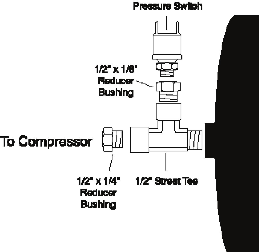
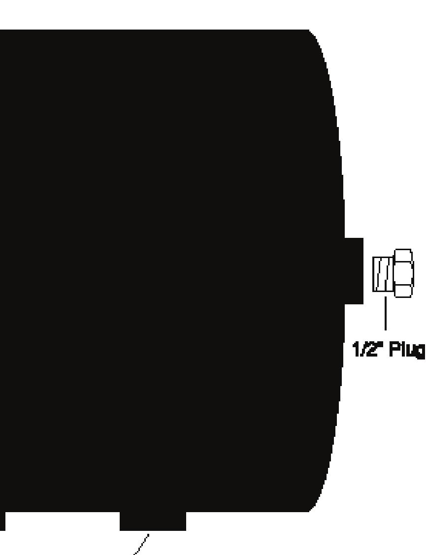
15 Setting Up the Tank NOTE: Use thread sealant provided to install all fi ttings. 1. Install a 1 /2 x 1 /8 bushing to the top of the air tank. Install the fi ll valve to the 1 /2 x 1 /8 bushing. (Figure 2). 2. Assemble a 1 /2 x 1 /4 bushing to the side of the street tee provided. Install the 145/175 p.s.i. pressure switch and a 3 /8 to 1 /8 reducer to the top of the tee. Install this assembly to the port on one end of the air tank (Figure 1). 3. Install the supplied plug to the other end of the air tank (Figure 1). 4. Install a 1 /2 to 1 /4 reducer bushing to the bottom port and attach the drain valve to the bushing. 5. Attach a 1 /2 x 3 /8 reducer bushing to a 3 /8 pipe nipple. Attach the 10mm fi ll valve to the nipple (Figure 2). NOTE: Make sure the In port faces the tank. Attach a 3 /8 nipple to the street tee facing down. Attach the dump valve with the In port facing the street tee. Attach a 3 /8 x 1 /2 tube fi tting to the other side of the dump valve. Install a 2-3 piece of 1 /2 hose to this fi tting. Attach a 3 /8 x 1 /2 tube 90 fi tting to the last port on the street tee. This port goes to the air strut (Figure 2). Assemble the valve assemblies this way for the two outer most ports on the tank (Figure 1). 6. Attach the two assemblies to the outer ports on the air tank, leaving the two inside ports empty for the other assemblies (Figure 1). 7. Assemble the inner valve assemblies in the same manner as detailed above, but leave the 3 /8 street tee and the dump valve off for now. In order to install the assemblies to the tank, the fi ll valves will need to be disassembled (Figure 2). Once the fi ll valve is taken apart, install the assemblies to the inner ports on the tank. 8. Install the tank assembly in an appropriate location and complete the installation by routing the air lines to 3
16 This kit should be installed after the air struts are in place. 1. Assemble the compressor by attaching the air fi lter to the inlet side as shown in Figure 3. IMPORTANT: If the compressor is mounted inside the vehicle, use caution. The compressor gets very hot and will burn or melt components. 2. The tank must be mounted so that the drain port is on the bottom of the tank. Run the steel-braided line from the compressor to the pressure switch assembly mounted on the air tank (Figure 3). Attach using the provided thread sealant. Plumb the rest of the system as shown in Figure 3. Route the lines as appropriate for your vehicle. IMPORTANT NOTE: When attaching the air fittings, be sure that a flat edge of the air fitting is facing downward as shown in figure 3A. If a point is facing downward, it may contact the sleeve and failure may result. 3. For wiring the solenoids, connect the appropriate wire from the switch on the gauge panel to one of the red solenoid wires and insure that the black solenoid lead is connected to a suitable chassis ground. Refer to Figure 4 to hook up solenoids and the sending unit and gauges. The infl ate solenoids are the ones mounted towards the top of the tank. The hot lead for these valves comes from the top terminal on the switches. The defl ate solenoids are the ones mounted towards the bottom of the tank. The hot lead for these valves comes from the bottom terminal on the switches. Ground the black wire on the back of the gauge. The white wire, is for the gauge light. Connect this wire to an appropriate dash light wire if you want the gauge light to operate in sync with the dash lights (on, off, dimming), or connect it to a keyed terminal on the fuse box if you want the light on continuously. 4. Wire the compressor as shown in Figure 4, connecting the red wire to one side of the pressure switch on the tank, and the black wire to a suitable ground. 5. Run a power wire for the system from an accessory terminal on the fuse box. NOTE: If using two compressors, add relays and connect to the positive side of the battery. Using an in-line fuse (30 amp), connect power to the remaining terminal on the pressure switch. Connect a 15 amp fuse from the accessory terminal on the fuse box to the middle terminal on all four gauge switches. 6. If connecting to an existing fuse, be sure to connect to the power side if the fuse in the fuse box. 7. IMPORTANT: This compressor is continuous duty, but in the event that the compressor stops running, allow the compressor to cool down and provide adequate time for the thermal breaker to reset before starting the compressor again. After the system is properly installed, it is ready to go. Insure that there is power to the system, let the pressure build in the system, and infl ate your air suspension. To improve recovery time in the tank, we recommend using two air compressors. If the tank is mounted inside the vehicle and you wish to drain it, put a rag under the drain valve and open the drain valve until the water has been cleared.


17 Figure 1
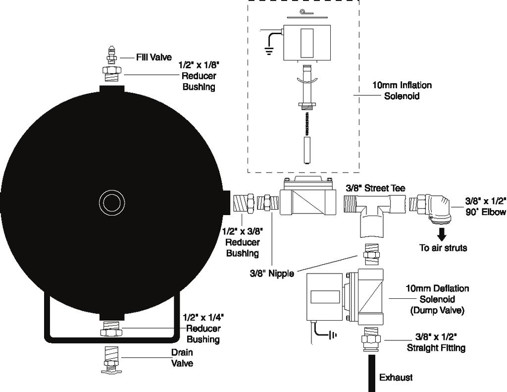
18 Figure 2

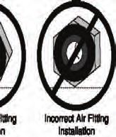
19 Figure 3A Figure 3
20 Figure 4
 322-2144 Fax: (517) 322-0240 http://www.airliftcompany.")
21 Thank you for purchasing Air Lift Products Mailing Address: Street Address: AIR LIFT COMPANY AIR LIFT COMPANY P.O. Box Snow Rd. Lansing, MI Lansing, MI Local Phone: (517) Fax: (517) For Technical Assistance call The Choice of the Professional Installer
92-00 Civic/ Integra/ Del Sol/ Accord/ CRX
 92-00 Civic/ 94-01 Integra/ 93-97 Del Sol/ 90-97 Accord/ 92-95 CRX Front Kit Part No. 75440 www.airliftperformance.com Please read these instructions completely before proceeding with installation MN-513
Neon Front Kit Part No
 EASYSTREET 1995-1999 Neon Front Kit Part No. 75588 www.airliftcompany.com MN-551 (07503) ECR 5014 Please read these instructions completely before proceeding with installation Warranty Information 1. All
92-00 Civic/ Integra/ Del Sol/ Accord/ CRX. Front Kit Part No
 LifeSTYLE 92-00 Civic/ 94-0 Integra/ 93-97 Del Sol/ 90-97 Accord/ 92-95 CRX Front Kit Part No. 75440 www.airliftcompany.com MN-53 (08409) NPR 4778 Please read these instructions completely before proceeding
Scion xa & xb Rear Kit Part No Please read these instructions completely before proceeding with installation
 Air Lift PERFORMANCE 2004-2005 Scion xa & xb Rear Kit Part No. 75672 www.airliftcompany.com MN-611 (051108) ECR 7072 Please read these instructions completely before proceeding with installation Warranty
92-00 Civic/ Integra/ Del Sol/ Accord/ CRX. Front Kit Part No
 LifeSTYLE 92-00 Civic/ 94-0 Integra/ 93-97 Del Sol/ 90-97 Accord/ 92-95 CRX Front Kit Part No. 75440 www.airliftcompany.com MN-53 (08409) NPR 4778 Please read these instructions completely before proceeding
03-05 Toyota Matrix & Pontiac Vibe Front Kit Part No
 EASYSTREET www.airliftcompany.com 03-05 Toyota Matrix & 01-05 Pontiac Vibe Front Kit Part No. 75585 MN-549 (04408) ECR 4717 Please read these instructions completely before proceeding with installation
00-03 Chevy Monte Carlo & Impala; Pontiac Grand Prix; Buick Century
 EASYSTREET www.airliftcompany.com 00-03 Chevy Monte Carlo & Impala; 97-03 Pontiac Grand Prix; 97-02 Buick Century Rear Kit Part No. 75629 MN-592 (02407) ECR 4670 Please read these instructions completely
Air Lift. Kit Honda Prelude ( ) PERFORMANCE INSTALLATION GUIDE
 PERFORMANCE INSTALLATION GUIDE") Air Lift PERFORMANCE Kit 75532 Honda Prelude (1992-2001) Cover illustration may not depict actual kit. MN-542 (06708) ECR 6206 INSTALLATION GUIDE For maximum effectiveness and safety, please read these
Air Lift PERFORMANCE Kit 75532 Honda Prelude (1992-2001) Cover illustration may not depict actual kit. MN-542 (06708) ECR 6206 INSTALLATION GUIDE For maximum effectiveness and safety, please read these
82-01 Chevy S-10/ GMC Sonoma Front Kit Part No B
 www.airliftcompany.com 82-01 Chevy S-10/ GMC Sonoma Front Kit Part No. 75512B MN-481 (02105) ECN 3549 Please read these instructions completely before proceeding with installation Left Side Upper Shock
92-00 Civic/ Integra/ Del Sol/ Accord/ CRX
 92-00 Civic/ 94-01 Integra/ 93-97 Del Sol/ 90-97 Accord/ 92-95 CRX Front Kit Part No. 75440 www.airliftperformance.com MN-513 (08409) NPR 4778 Please read these instructions completely before proceeding
69-74 VW Beetle IRS Rear Kit Part No
 www.airliftcompany.com 69-74 VW Beetle IRS Rear Kit Part No. 75615 MN-476 (01102) ECN 3455 Please read these instructions completely before proceeding with installation A C B E D AA F F ITEM QTY. PART
92-00 Civic/ Integra/ Del Sol/ Accord/ CRX
 92-00 Civic/ 94-01 Integra/ 93-97 Del Sol/ 90-97 Accord/ 92-95 CRX Front Kit Part No. 75440 www.airliftperformance.com MN-513 (08409) NPR 4778 Please read these instructions completely before proceeding
Please read these instructions completely before proceeding with installation. Read all maintenance guidelines on page 7 before operating the vehicle.
 MN-643 (02511) ECR 5461 Kit No. 39205 Please read these instructions completely before proceeding with installation Item P/N Description Quantity A 26391 Driver-Side Beam Assembly 1 B 26414 Passenger-Side
Kit No Please read these instructions completely before proceeding with installation. Air Spring Kit Parts List. Bracket Attaching Hardware
 Kit No. 59532 MN-572 (021108) ECR 7136 Please read these instructions completely before proceeding with installation Air Spring Kit Parts List A Item Description Quantity A Air Sleeves 2 B Upper Brackets
Air Commander Part No , with air Part No , without air
 EASYSTREET Air Commander Part No. 27325, with air Part No. 27332, without air www.airliftcompany.com Please read these instructions completely before proceeding with installation. The oil level in the
Air Lift. Kit PERFORMANCE INSTALLATION GUIDE Scion xb
 Air Lift PERFORMANCE Kit 75599 2008 Scion xb MN-687 (031111) ECR 7189 INSTALLATION GUIDE For maximum effectiveness and safety, please read these instructions completely before proceeding with installation.
Frame. Axle. Kit No Please read these instructions completely before proceeding with installation. Figure 1. Kit Parts List FORWARD B J
 Kit No. 70 Please read these instructions completely before proceeding with installation by www.airliftcompany.com MN-7 (008) ECN 08 Item P/N Description Qty. A B C D E F H I 807 0770 0006 88 70 87 8 8
Kit No Please read these instructions completely before proceeding with installation. Parts List G J I K L H CC FF DD MN-505 (01201) NPR 3733
 NPR 3733") Kit No. 57154 MN-505 (01201) NPR 3733 Please read these instructions completely before proceeding with installation Parts List by www.airliftcompany.com Item P/N Description Quantity A 58407 Air Spring
Kit No. 57154 MN-505 (01201) NPR 3733 Please read these instructions completely before proceeding with installation Parts List by www.airliftcompany.com Item P/N Description Quantity A 58407 Air Spring
Kit No Please read these instructions completely before proceeding with installation. Air Spring Kit Parts List. Attaching Hardware
 Kit No. 57340 MN-431 (02409) NPR 4796 Please read these instructions completely before proceeding with installation by www.airliftcompany.com Air Spring Kit Parts List A B1 B2 Item Description Quantity
95-99 Mitsubishi Eclipse & Eagle Talon
 www.airliftcompany.com 95-99 Mitsubishi Eclipse & Eagle Talon Front Kit Part No. 75581 Please read these instructions completely before proceeding with installation MN-565 (09409) ECR 4762 Warranty Information
Pneumatic Control System Kit No
 MN-634 (05609) ECR 5791 Pneumatic Control System Kit No. 27225 Please read these instructions completely before proceeding with installation Failure to read these instructions can result in mis-installation
Part # Mopar LX Level 1 Air Suspension System
 Part # 13040199 05-14 Mopar LX Level 1 Air Suspension System Front Components: 1 1304409 Front RQ ShockWave Kit for Stock Lower Arms Rear Components: 1 13044099 Rear CoolRide Kit 1 13040709 RQ Series Rear
Air Lift. Kit PERFORMANCE INSTALLATION GUIDE Scion xb
 Air Lift PERFORMANCE Kit 75699 2008- Scion xb MN-689 (041108) ECR 7072 INSTALLATION GUIDE For maximum effectiveness and safety, please read these instructions completely before proceeding with installation.
Kit No Please read these instructions completely before proceeding with installation. Figure 1 MN-614 (06601) ECR
 ECR") Kit No. 57291 MN-614 (06601) ECR 5445 Please read these instructions completely before proceeding with installation. by www.airliftcompany.com Figure 1 1 Hardware List Item Part No. Description Quantity
Kit No. 57291 MN-614 (06601) ECR 5445 Please read these instructions completely before proceeding with installation. by www.airliftcompany.com Figure 1 1 Hardware List Item Part No. Description Quantity
Please read these instructions completely before proceeding with the installation.
 Fits Multi-Leaf Steel Spring Models Only. P/N 59111 This kit is for a 2" drop Please read these instructions completely before proceeding with the installation. by MN-346 (03006) ECN3100 Nylon Nut Upper
Kit No Please read these instructions completely before proceeding with installation. Air Spring Kit Parts List. Bracket Attaching Hardware
 Kit No. 59537 MN-461 (021108) ECR 7136 Please read these instructions completely before proceeding with installation Air Spring Kit Parts List Item Description Quantity A Air Sleeves 2 B Upper Brackets
Air Commander Part No
 EASYSTEET Air Commander Part No. 26903 www.airliftcompany.com MN-510 (06506) EC 5206 Please read these instructions completely before proceeding with installation The oil level in the compressor must be
Ford Ranger Rear Kit Part No
 EASYSTREET Ford Ranger Rear Kit Part No. 75621 www.airliftcompany.com MN-487 (03202) ECN3773 Please read these instructions completely before proceeding with installation Item P/N Description Qty. A 10177
Air Commander Late Model Ford F-150
 EASYSTREET Air Commander Late Model Ford F-150 www.airliftcompany.com MN-544 (02506) ECR 5206 Please read these instructions completely before proceeding with installation The oil level in the compressor
Please read these instructions completely before proceeding with the installation. Press Lock Swivel Elbow Fitting. Air Sleeve.
 P/N 59506 Please read these instructions completely before proceeding with the installation. CAUTION: Failure to maintain correct minimum pressure (or pressure proportional to the load), bottoming out,
92-00 Civic/ Integra/ Del Sol/ Accord/ CRX
 92-00 Civic/ 94-01 Integra/ 93-97 Del Sol/ 90-97 Accord/ 92-95 CRX Front Kit Part No. 75440 www.airliftperformance.com MN-513 (08409) NPR 4778 Please read these instructions completely before proceeding
92-00 Civic/ Integra/ Del Sol/ Accord/ CRX
 92-00 Civic/ 94-01 Integra/ 93-97 Del Sol/ 90-97 Accord/ 92-95 CRX Front Kit Part No. 75440 www.airliftperformance.com MN-513 (08409) NPR 4778 Please read these instructions completely before proceeding
Kit No Please read these instructions completely before proceeding with installation. Figure 1. Forward. Passenger-Side View
 Kit No. 57345 90 Air Fitting (G) MN-520 (01206) NPR 3902 Please read these instructions completely before proceeding with installation by www.airliftcompany.com 7 16 "-14 Lock Nut (E) Air Line (AA) Upper
KIT No , and 80590
 KIT No. 80531, 80545 and 80590 by MN-354 (05603) ECR 5593 Please read these instructions completely before proceeding with installation Air Spring Kit Parts List Item Description Quantity A Air Spring
Kits (with shocks), (no shocks) Audi B9
, (no shocks) Audi B9") Kits 78670 (with shocks), 78671 (no shocks) Audi B9 Rear Application MN-1074 (011808) ERN 8788 INSTALLATION GUIDE For maximum effectiveness and safety, please read these instructions completely before
Kits 78670 (with shocks), 78671 (no shocks) Audi B9 Rear Application MN-1074 (011808) ERN 8788 INSTALLATION GUIDE For maximum effectiveness and safety, please read these instructions completely before
R4TECH PRODUCT SAFETY NOTICE
 R4TECH PRODUCT SAFETY NOTICE Congratulations. This vehicle has been equipped with an R4Tech suspension system that provides the ride quality of a full-air suspension with the ease of installation of a
Kits 75559, & Universal Air Spring-Over-Strut
 Kits 75559, 75561 & 75562 Universal Air Spring-Over-Strut MN-723 (061901) ECR 8657 NOTE: THIS KIT IS SOLD WITHOUT A WARRANTY. INSTALLATION GUIDE For maximum effectiveness and safety, please read these
Kit No (THIS KIT IS FOR A 2" AND 4" DROP)
") Kit No. 59103 (THIS KIT IS FOR A 2" AND 4" DROP) by MN-348 (06005) ECN 3080 Please read these instructions completely before proceeding with installation. Air Spring Kit Parts List Item Description Quantity
Kit No. 59103 (THIS KIT IS FOR A 2" AND 4" DROP) by MN-348 (06005) ECN 3080 Please read these instructions completely before proceeding with installation. Air Spring Kit Parts List Item Description Quantity
Part # C-10 Level 1 Air Suspension System
 350 S. St. Charles St. Jasper, In. 47546 Part # 11330199 63-72 C-10 Level 1 Air Suspension System Front Components: 1 11331099 Front CoolRide Kit for Stock Lower Arms 1 11330509 RQ Series Front Shock Kit
Kit INSTALLATION GUIDE. Front Application. Scion xa & xb
 Kit 75572 Scion xa & xb Front Application MN-610 (101710) ECR 8900 INSTALLATION GUIDE For maximum effectiveness and safety, please read these instructions completely before proceeding with installation.
INSTALLATION GUIDE. Magnetic Height Sensor. No , 25430
 Magnetic Height Sensor No. 25415, 25430 MN-601 (11610) ECR 5863 INSTALLATION GUIDE For maximum effectiveness and safety, please read these instructions completely before proceeding with installation. Failure
ONBOARD AIR SYSTEM FOR ALL VEHICLES APPLICATIONS
 ONBOARD SYSTEM FOR ALL VEHICLES APPLICATIONS Thank you and congratulations on the purchase of a Pacbrake onboard air system. Please read the manual prior to starting to ensure you can complete the installation
Part # Galaxie Level 1 Complete Air Suspension System
 350 S. St. Charles St. Jasper, In. 47546 Ph. 812.482.2932 Fax 812.634.6632 www.ridetech.com Part # 12160199 60-64 Galaxie Level 1 Complete Air Suspension System Front Components: 1 12162409 Front RQ Series
PRODUCT SAFETY NOTICE
 PRODUCT SAFETY NOTICE Congratulations. This vehicle has been equipped with a Firestone air suspension system. This suspension will enhance the vehicle s handling when loaded, however, the vehicle s performance
ʻ92-ʼ00 Civic/ʼ94-ʼ01 Integra/ ʻ93-ʼ97 Del Sol/ʼ90-ʼ97 Accord/ ʻ92-ʼ95 CRX
 ʻ92-ʼ00 Civic/ʼ94-ʼ0 Integra/ ʻ93-ʼ97 Del Sol/ʼ90-ʼ97 Accord/ ʻ92-ʼ95 CRX Front Kit Part No. 75440 www.airliftperformance.com MN-53 (08409) NPR 4778 Please read these instructions completely before proceeding
P/N 59508,Dakota 2WD Models Only
 P/N 59508,Dakota 2WD Models Only by MN-263 (071108) ECR 7136 Please read these instructions completely before proceeding with the installation. 3/8" Nylon Lock Nut Oversized Washer Frame Press Lock Elbow
Kits Installation Guide. Dodge/RAM WD and 4WD
 S E R I E S TM Installation Guide Dodge/RAM 1500 2WD and 4WD Kits 57370 88370 89370 For maximum effectiveness and safety, please read these instructions completely before proceeding with installation.
P/N Figure 1. Figure 2. 3 Valve Stem
 P/N 80523 BY MN-75 (12612) ECN1965 ECR 8167 3 Valve Stem 2 1 Figure 1 1 1. Jack up front end of vehicle and place safety stands under axle. Remove front wheels and lower shock absorber attaching bolts.
Kit Honda Odyssey, Honda Pilot, & Acura MDX
 TM Kit 60815 Honda Odyssey, Honda Pilot, & Acura MDX Cover illustration may not depict actual kit. MN-692 (041801) ECR 8900 INSTALLATION GUIDE For maximum effectiveness and safety, please read these instructions
Please read these instructions completely before proceeding with the installation. Hardware Identification. (1) Barbed Tee. (6) Air Line Clamp
 Barbed Tee. (6) Air Line Clamp") by MN-446 (01007) ECN3102 Kit No. 60788 Please read these instructions completely before proceeding with the installation. Hardware Identification (1) Barbed Tee (4) Hex Nut (2) 5/16" Flat Washer (6) Air
by MN-446 (01007) ECN3102 Kit No. 60788 Please read these instructions completely before proceeding with the installation. Hardware Identification (1) Barbed Tee (4) Hex Nut (2) 5/16" Flat Washer (6) Air
HP10207 KIT. Ram WD*
 HP10207 KIT Ram 1500 4WD* (For 2WD call customer service 800.663.0096 for assistance) * See application guide for proper fitment. Use the most advanced air springs on the market to eliminate your vehicle
P/N 59511, NEVER EXCEED THE MANUFACTURERS MAXIMUM GROSS VEHICLE WEIGHT RATING. DO NOT INSTALL THE AIR SPRING AS THE PRIMARY SUSPENSION SPRING.
 MN-260 (10901) ECR6622 P/N 59511, 59611 NEVER EXCEED THE MANUFACTURERS MAXIMUM GROSS VEHICLE WEIGHT RATING. DO NOT INSTALL THE AIR SPRING AS THE PRIMARY SUSPENSION SPRING. THIS PRODUCT IS INTENDED FOR
Air Commander
 EASYSTREET Air Commander www.airliftcompany.com MN-507 (03206) ECN 3921 Please read these instructions completely before proceeding with installation. The oil level in the compressor must be checked BEFORE
TOYOTA FJ CRUISER 6 SUSPENSION KIT
 92177000 TOYOTA FJ CRUISER 6 SUSPENSION KIT Thank you for choosing Rough Country for your suspension needs. Rough Country recommends a certified technician installs this system. In addition to these instructions,
Air Lift. Kit Dodge Charger, Challenger, 300C, and Magnum PERFORMANCE INSTALLATION GUIDE. (includes SRT 8 models, excludes AWD models)
") Air Lift PERFORMANCE Kit 75595 Dodge Charger, Challenger, 300C, and Magnum (includes SRT 8 models, excludes AWD models) MN-661 (031111) ECR 7189 INSTALLATION GUIDE For maximum effectiveness and safety,
Air Lift PERFORMANCE Kit 75595 Dodge Charger, Challenger, 300C, and Magnum (includes SRT 8 models, excludes AWD models) MN-661 (031111) ECR 7189 INSTALLATION GUIDE For maximum effectiveness and safety,
Air Lift. Kit & Universal Sleeve-Over-Shocks PERFORMANCE INSTALLATION GUIDE NOTE: THIS KIT IS SOLD WITHOUT A WARRANTY.
 Air Lift PERFORMANCE Kit 75566 & 75569 Universal Sleeve-Over-Shocks MN-749 (031111) ECR 7189 NOTE: THIS KIT IS SOLD WITHOUT A WARRANTY. INSTALLATION GUIDE For maximum effectiveness and safety, please read
Kit INSTALLATION GUIDE. Honda Odyssey, Honda Pilot, & Acura MDX
 Kit 60815 Honda Odyssey, Honda Pilot, & Acura MDX Cover illustration may not depict actual kit. MN-692 (021202) ECR 7276 INSTALLATION GUIDE For maximum effectiveness and safety, please read these instructions
Kit Chevrolet/GMC Heavy Duty. Installation Guide
 Installation Guide Kit 57538 Chevrolet/GMC Heavy Duty Representative vehicle image MN-1034 (021810) ECR 9155 For maximum effectiveness and safety, please read these instructions completely before proceeding
Carli Suspension Front Instructions
 Carli Suspension Front Instructions 94-08 DODGE 2500-3500 4X4 SUSPENSION SYSTEM Note: Prior to installation, carefully inspect the vehicle=s steering and drive train components. Be sure to check ball joints,
Kit No Please read these instructions completely before proceeding with installation. Figure 1. Parts Included
 Kit No. 59501 Please read these instructions completely before proceeding with installation by www.airliftcompany.com MN-324 (19410) ECN 4833 Parts Included K Item Description Quantity A Air Spring 2 B
I. Preparing the Vehicle
 Multiple Applications See special notes for your particular vehicle. I. Preparing the Vehicle by MN-169 (11809) ECR 6529 NOTE For Toyota Sequoias: Before proceeding with the installation, measure up 6.75
FIGURE 2 FIGURE Remove the rubber jounce bumper. This will not be reused.
 3/8-16x1.5" WHFB Upper Brace Frame Lockwasher 5/16-18x1 1/2" Carriage Bolt Straight end 3/8-16 Locknut 3/8 Lockwasher 3/8-16x1" HHCS 5/16-18 Lock Nut Bellows 5/16 Flatwasher 3/8-16x1" HHCS FIGURE 2 Upper
FAX
 INSTALLATION INSTRUCTIONS 6090 Air Suspension Kit (pat. pending) 1999-2006 Tahoe, Suburban, Avalanche, Yukon Thank you for purchasing a quality Hellwig Product. PLEASE READ THIS INSTRUCTION SHEET COMPLETELY
Part # Chevy Level 2 Air Suspension Package One Piece Frame
 350 S. St. Charles St. Jasper, In. 47546 Ph. 812.482.2932 Fax 812.634.6632 www.ridetech.com Part # 11020299 55-57 Chevy Level 2 Air Suspension Package One Piece Frame Front Components: 1 11013001 Master
READ AND UNDERSTAND ALL INSTRUCTIONS AND WARNINGS PRIOR TO INSTALLATION OF SYSTEM AND OPERATION OF VEHICLE.
 #021700, 021701 7 Suspension System 2000-2004 Chevy/GMC 1500 2wd Extended Cab w/ Front Coil Springs READ AND UNDERSTAND ALL INSTRUCTIONS AND WARNINGS PRIOR TO INSTALLATION OF SYSTEM AND OPERATION OF VEHICLE.
2014 GM 1500 TRUCK STOP---READ THIS FIRST! 7" Lift KIT. **Read These Entire Instructions Before Starting Anything**
 STOP---READ THIS FIRST! **Read These Entire Instructions Before Starting Anything** 2014 GM 1500 TRUCK LIFT KIT INSTRUCTIONS (PART #50768 & #50769 ) 5680 W. Barstow, Fresno, CA 93722 PH: (559) 226-8196
Ford E-450 Kit No Please read these instructions completely before proceeding with installation
 MN-633 (12704) ECR 6107 Ford E-450 Kit No. 39217 Please read these instructions completely before proceeding with installation Failure to read these instructions can result in mis-installation Introduction
Air Commander Part No
 EASYSTREET Air Commander Part No. 26901 www.airliftcompany.com MN-508 (05504) NPR 5129 Please read these instructions completely before proceeding with installation Front View Side View Hardware Item P/N
Introduction Important Safety Notice...2 Notation Explanation...2. Hardware List...4. Attaching the Compressor...4. Wiring the System...
 LifeSTYLE Kits 27665/27666 Cover illustration may not depict actual kit. MN-726 (02002) ECR 684 INSTALLATION GUIDE For maximum effectiveness and safety, please read these instructions completely before
Installation Instructions
 Part # 12150299-2005 Up Mustang Level 2 Shockwave System Front Components: 12152401 Front ShockWave Strut Recommended Tools Rear Components: 12155401 Rear ShockWave Miscellaneous Components: 30334000 3
Kit INSTALLATION GUIDE. For maximum effectiveness and safety, please read these instructions completely before proceeding with installation.
 Kit 25801 MN-208 (121506) ECR 8243 INSTALLATION GUIDE For maximum effectiveness and safety, please read these instructions completely before proceeding with installation. Failure to read these instructions
STOP---READ THIS FIRST!
 STOP---READ THIS FIRST! **Read These Entire Instructions Before Starting Anything** 2007-2010 GM 1500 TRUCK LIFT KIT INSTRUCTIONS (PART# 50700 & 50720) 5680 W. Barstow, Fresno, CA 93722 PH: (559) 226-8196
STOP---READ THIS FIRST!
 STOP---READ THIS FIRST! **Read These Entire Instructions Before Starting Anything** 2007-2013 GM 1500 TRUCK LIFT KIT INSTRUCTIONS (PART# 50700 & 50720) 5680 W. Barstow, Fresno, CA 93722 PH: (559) 226-8196
Kit No BT. FOR 6" C NOTCH BELL TECH Please read these instructions completely before proceeding with installation.
 Kit No. 59106BT FOR 6" C NOTCH BELL TECH Please read these instructions completely before proceeding with installation. by MN-283 (061108) ECR 7136 Nylon Lock Nut Large Flat Washer Press Lock Elbow Fitting
Kit Number INSTALLATION GUIDE ADJUSTABLE AIR HELPER SPRINGS TOW AND HAUL WITH SAFETY AND COMFORT TM
 ADJUSTABLE AIR HELPER SPRINGS TOW AND HAUL WITH SAFETY AND COMFORT TM Kit Number 88205 INSTALLATION GUIDE For maximum effectiveness and safety, please read these instructions completely before proceeding
Installation Manual v1.0: Aurora Plus Turbo Kit ( ) 5.9L Dodge. Please read all instructions before installation.
 5.9L Dodge. Please read all instructions before installation.") Installation Manual v1.0: Aurora Plus - 4000 Turbo Kit (2003-2007) 5.9L Dodge Please read all instructions before installation. Figure 1: Aurora Plus - 4000 Kit Contents 1 Figure 2: Aurora Plus Hardware
Installation Manual v1.0: Aurora Plus - 4000 Turbo Kit (2003-2007) 5.9L Dodge Please read all instructions before installation. Figure 1: Aurora Plus - 4000 Kit Contents 1 Figure 2: Aurora Plus Hardware
No INSTALLATION GUIDE. Chevrolet Silverado 1500 and GMC Sierra 1500
 No. 59565 Chevrolet Silverado 1500 and GMC Sierra 1500 INSTALLATION GUIDE MN-670 (01701) For maximum effectiveness and safety, please read these instructions completely before proceeding with installation.
For Multiple Applications See special notes for your particular vehicle.
 For Multiple Applications See special notes for your particular vehicle. by MN-131 (10304) ECN4192 Please read these instructions completely before proceeding with the installation. Escort, Lynx Escort
Tools Needed. I. Getting Started
 5 /16 ", 7 /16 ", 9 /16 " and 19mm open-end or box wrenches Crescent Wrench Ratchet with 9 /16 " and 1 /2 " deep well sockets 3 /8 " and 5 /16 " drill bits (very sharp) Heavy Duty Drill Torque Wrench Tools
PARTS LIST: 8581 DODGE LONG ARM BRACKETS 03-13
 SYNERGY MFG. 870 INDUSTRIAL WAY, SAN LUIS OBISPO, CA (805) 242-0397 8580 03-12 DODGE 2500/3500 4X4, 06-08 1500 MEGACAB 4X4 LONG ARM SUSPENSION KIT V3.0 GENERAL NOTES: These instructions are also available
PRODUCT SAFETY NOTICE DEALER/INSTALLER NOTICE
 PRODUCT SAFETY NOTICE Congratulations. This vehicle has been equipped with a Firestone air suspension system. This suspension will enhance the vehicle s handling when loaded, however, the vehicle s performance
05 12 TOYOTA TACOMA 2WD
 MAXTRAC SUSPENSION 4030 E LEAVERTON CT ANAHEIM, CA 92807 714 630 0363 WWW.MAXTRACSUSPENSION.COM SALES@MAXTRACSUSPENSION.COM PRODUCT: PARTS LIST K756864 6" LIFT KIT 05 12 TOYOTA TACOMA 2WD QTY SPINDLE,
Suspension System RS6582B
 Suspension System RS6582B Tahoe/Yukon READ ALL INSTRUCTIONS THOROUGHLY FROM START TO FINISH BEFORE BEGINNING INSTALLATION IMPORTANT NOTES! WARNING: This suspension system will enhance the off-road performance
07-UP AVALANCHE 7.5 KIT
 92120900R1 07-UP AVALANCHE 7.5 KIT Thank you for choosing Rough Country for your suspension needs. We appreciate your business!! This kit will not fit vehicles equipped with electric steering or trucks
Kits 25490, Automatic Self-Leveling System
 II Kits 25490, 25491 Automatic Self-Leveling System 3 Y fuse For mini (ATM) fuse doubles (011608) ECR 8403 ORDER OF INSTALLATON height 1. Install electronic magnet sensor and bracket. r and 2. Install
Kit No KIT FITS 2" & 4" DROPS
 Kit No 59104 KIT FITS 2" & 4" DROPS NOTE: If the bottom of the frame to the leaf spring is 70 or less, we do not fit your application Please read these instructions completely before proceeding with installation
HP10220 KIT. See application guide for proper fitment.
 HP10220 KIT Dodge Dakota* (2WD/4WD) * 2005 All Dodge Dakotas 2006 - All Dodge Dakotas except Night Runner and R/T sub models 2007 - All Dodge Dakotas except SXT and TRX4 sub models 2008 - All Dodge Dakotas
LifeSTYLE. Kit Installation GuidE. Scion tc. front application
 LifeSTYLE Kit 75587 Scion tc front application MN-716 (01905) ERN 6606 Installation GuidE For maximum effectiveness and safety, please read these instructions completely before proceeding with installation.
PERFORMANCE SUSPENSION PARTS
 PERFORMANCE SUSPENSION PARTS Introduction Air Lift Performance The purpose of this publication is to assist with the installation, maintenance and troubleshooting of this Audi A6 C5 Performance kit. It
INSTALLATION INSTRUCTIONS
 28 INSTALLATION INSTRUCTIONS SECTION - AIR SPRING SECTION 2 - AIR ACCESSORY 2-5 ! IMPORTANT PLEASE DON T HURT YOURSELF, YOUR KIT OR YOUR VEHICLE. TAKE A MINUTE TO READ THIS IMPORTANT INFORMATION. This
I. Assembling the Air Spring
 B F H G D FRONT I Assembling the Air Spring 1 Install 90 degree air swivel fitting (D) to the top of the bellow This fitting is precoated with sealant Using an open-end wrench, tighten 1 and 1 /2 turns
Driver Side Shown P/N Figure 1
 P/N 59544 by MN-612 (05606) ECR 5714 Please read these instructions completely before proceeding with the installation. NOTE: Unbolt the lower bracket from the leaf spring if the vehicle is to be serviced
Installation Instructions
 Part # 099-00 Up Mustang Level Shockwave System Front Components: 0 Front ShockWave Strut Recommended Tools Rear Components: 0 Rear ShockWave Miscellaneous Components: 3033000 3 Gallon Compressor System
INSTALLATION INSTRUCTION 88094
 INSTALLATION INSTRUCTION 88094 FOR RANCHO SUSPENSION SYSTEM RS6594B 4WD & 2WD NISSAN TITAN READ ALL INSTRUCTIONS THOROUGHLY FROM START TO FINISH BEFORE BEGINNING INSTALLATION Rev D IMPORTANT NOTES! WARNING:
Part # C-10 Level 2 Complete Air Suspension System
 350 S. St. Charles St. Jasper, In. 47546 Ph. 812.482.2932 Fax 812.634.6632 www.ridetech.com Part # 11340299 63-70 C-10 Level 2 Complete Air Suspension System Front Components: 1 11330999 Front CoolRide
Super Duty Front Air Bag Installation Instructions
 2005-2010 Super Duty Front Air Bag Installation Instructions Congratulations! You have just purchased the best engineered, highest quality front air suspension kit available on the market for your 2005-2010
Air Lift. Kit Honda Civic (8th GEN) PERFORMANCE INSTALLATION GUIDE. Front Application
 PERFORMANCE INSTALLATION GUIDE. Front Application") Air Lift PERFORMANCE Kit 78524 Honda Civic (8th GEN) Front Application INSTALLATION GUIDE PERFORMANCE SUSPENSION PARTS For maximum effectiveness and safety, please read these instructions completely before
Air Lift PERFORMANCE Kit 78524 Honda Civic (8th GEN) Front Application INSTALLATION GUIDE PERFORMANCE SUSPENSION PARTS For maximum effectiveness and safety, please read these instructions completely before
Air Lift. Kit PERFORMANCE INSTALLATION GUIDE. Scion tc. front application
 Air Lift PERFORMANCE Kit 75587 Scion tc front application MN-716 (031111) ECR 7189 INSTALLATION GUIDE For maximum effectiveness and safety, please read these instructions completely before proceeding with
P/N Retaining Collar. U-BOLT Lower Pedestal REARWARD OUTBOARD
 P/N 59202 MN-406 (01903) NPR2670 1/2" Flat Nut Lock Washer 1/2" Flat Washer Straight Fitting 3/8"x7/8" Hex Head Bolt 3/8" Lock Washer Bell Tech Frame Section Upper Bracket 1/2"-13 x 1.5 " Carriage Bolt
Rear Toyota Landcruiser 4x4 S-W GX 91 Onwards
 60728A0 Rear Toyota Landcruiser 4x4 S-W 80-100 GX 91 Onwards LOWER SPRING SEAT.DRILLING INSTRUCTIONS 6. The picture above shows the expected result after drilling the hole in step 4. 1. The spring seat