Air Lift. Kit PERFORMANCE INSTALLATION GUIDE Scion xb
|
|
|
- Coral Ariel Gallagher
- 5 years ago
- Views:
Transcription


1 Air Lift PERFORMANCE Kit Scion xb MN-687 (031111) ECR 7189 INSTALLATION GUIDE For maximum effectiveness and safety, please read these instructions completely before proceeding with installation. Failure to read these instructions can result in an incorrect installation.
2
3 TABLE OF CONTENTS Introduction Important Safety Notice...2 Notation Explanation...2 Installation Diagram... 3 Hardware List...3 Tools List...3 Installing the Air Suspension Preparing the Vehicle...4 Removing the Strut...4 Installing the New Strut Assembly...5 Aligning the Vehicle...6 Before Operating Installation Checklist...7 Maintenance and Servicing... 8 Minimum and Maximum Air Pressures...8 Maintaining and Operating...8 Replacement Information Warranty and Returns Policy Contact Information... 9 MN-687 1
4 Introduction Air Lift Performance The purpose of this publication is to assist with the installation, maintenance and troubleshooting of this Scion Air Lift Performance kit. It is important to read and understand the entire installation guide before beginning installation or performing any maintenance, service or repair. The information includes a hardware list, tool list, step-by-step installation information, maintenance tips, safety information and a troubleshooting guide. Air Lift Company reserves the right to make changes and improvements to its products and publications at any time. For the latest version of this manual, contact Air Lift Company at (800) or visit our website at IMPORTANT SAFETY NOTICE The installation of this kit does not alter the Gross Vehicle Weight Rating (GVWR) or payload of the vehicle. Check your vehicle s owner s manual and do not exceed the maximum load listed for your vehicle. Gross Vehicle Weight Rating: The maximum allowable weight of the fully loaded vehicle (including passengers and cargo). This number along with other weight limits, as well as tire, rim size and inflation pressure data is shown on the vehicle s Safety Compliance Certification Label. Payload: The combined, maximum allowable weight of cargo and passengers that the truck is designed to carry. Payload is GVWR minus the Base Curb Weight. NOTATION EXPLANATION Hazard notations appear in various locations in this publication. Information which is highlighted by one of these notations must be observed to help minimize risk of personal injury or possible improper installation which may render the vehicle unsafe. Notes are used to help emphasize areas of procedural importance and provide helpful suggestions. The following definitions explain the use of these notations as they appear throughout this guide. DANGER WARNING CAUTION NOTE INDICATES IMMEDIATE HAZARDS WHICH WILL RESULT IN SEVERE PERSONAL INJURY OR DEATH. INDICATES HAZARDS OR UNSAFE PRACTICES WHICH COULD RESULT IN SEVERE PERSONAL INJURY OR DEATH. INDICATES HAZARDS OR UNSAFE PRACTICES WHICH COULD RESULT IN DAMAGE TO THE MACHINE OR MINOR PERSONAL INJURY. Indicates a procedure, practice or hint which is important to highlight. 2 MN-687
5 Installation Diagram B C F1 OR F2 A1 fig. 1 HARDWARE LIST Item Part # Description... Qty A Gen II front strut (left)...1 A Gen II front strut (right, not shown)...1 B /8-16 Nyloc nut...6 C /8 Flat washer...6 D /4-20 x.75 Bolt...2 E /4-20 Nyloc nut...2 F Fitting - 1/4NPT X 1/4PTC, Elbow...2 F Fitting - 1/4NPT X 3/8PTC, Elbow...2 G Flat washer...4 TOOLS LIST E G D Lower hole in brake line retainer Description... Qty Jack... 1 Jack stands or hoist... 2 ½ Drive ratchet mm Socket mm Wrench mm Wrench mm Wrench & socket... 1 ¾ Socket /16 Socket & end wrench... 1 Straight flathead screwdriver... 1 Torque wrench /2 Socket & wrench... 1 STOP! Missing or damaged parts? Call Air Lift customer service at (800) for a replacement part. MN-687 3
6 Installing the Air Suspension CAUTION PREPARING THE VEHICLE 1. Elevate the vehicle and support the body with a hoist or jack stands. 2. Remove the front wheels. REMOVING THE STRUT 1. Remove the brake line and ABS retainer bolt; these will no longer be needed. 2. Unbolt the sway bar link from the strut. 3. Using a screwdriver, unclip the ABS line from the retainer. 4. Remove the two lower retaining bolts from the spindle and save for reinstallation (fig. 2). MAKE SURE TO SUPPORT THE LOWER SPINDLE/AXLE ASSEMBLY SO AS NOT TO PULL APART THE CV JOINT ON THE AXLE. 5. Remove the three upper retaining nuts; these will no longer be needed (fig. 3). Lower strut mounting bolts Upper strut mounting nuts Nyloc nut Inside the engine compartment fig. 2 fig Remove the strut from the vehicle and discard (fig. 4). Strut assembly fig. 4 4 MN-687
7 INSTALLING THE NEW STRUT ASSEMBLY 1. Prior to installing the strut, attach the air fitting provided to the threaded port at the top of the air spring (fig. 5). Seal with teflon tape. Correct air fitting installation: Hex nut edges are parrallel with top and bottom upper end cap edges. fig. 5 Incorrect air fitting installation: Hex nut point extends over bottom of upper end cap edge and could puncture the air bag. NOTE 2. In each inner fender well, in the area surrounding the strut location, check for any screws longer than 1/4. Grind these screws down to less than 1/4. 3. Insert the new strut into the vehicle s strut pocket (fig. 6). Each strut is specific to one side of the vehicle only; the strut labeled fits on the left, driver-side of the vehicle; the other strut labeled fits on the right, passenger-side of the vehicle. fig. 6 NOTE 4. Secure the top of the strut in place using the 3/8 nyloc nuts (B), and washers (C) provided. IMPORTANT: Torque to 27 ft/lbs. 5. Raise the suspension to align the lower strut mount holes with the spindle. Check the head-to-strut clearance. Reattach using the previously removed factory bolts. When aligning, use of Loctite Red or a similar thread sealant on the nut is recommended. MN-687 5
8 NOTE 6. Reattach the ABS and brake lines using the 1/4 bolt (D), nyloc nut (E), and washers (G). Use the lower holes in the brake line bracket on the strut for reattaching the brake/abs line (fig. 1 and fig. 7). Sway bar tab Brake line bracket fig. 7 NOTE CAUTION 7. Reattach the sway bar using the original hardware (fig. 7). 8. Attach the air hose to the air fitting at the top of the strut. ALIGNING THE VEHICLE 1. Using the control system, set the vehicle to the new custom ride height. 2. If the custom ride height is lower than stock, we recommend loosening all pivot points (bolts, nuts) on any control arm, strut arm or radius rod that contains bushings. Once they have been loosened, re-torque to stock specifications. It may be necessary to cycle the suspension to loosen the bushing up from its mount. This will help unload the bushing to make it last longer at its new position based on the custom ride height. KEEP SAFETY IN MIND WHEN DOING THIS AND SECURE ANY ITEMS THAT COULD COME LOOSE FROM THE VEHICLE. 3. The struts have slots built in for proper alignment at your new custom ride height. Have a four-corner alignment done from a qualified technician using the proper alignment tools. 4. Tighten all mounting hardware securely to the manufacturer s torque specifications. 6 MN-687
9 Before Operating 1. The struts for this vehicle come with a nine-position dampening dial for added adjustability (fig. 8). Before driving your vehicle, set the new struts to their highest setting by turning the black dial on the shaft of the strut as far as it will go to the right (position 9). Decrease dampening Increase dampening fig. 8 CAUTION 2. Next, completely deflate and reinflate the air bags 2-3 times to evenly distribute the air that may have shifted during shipping. For normal ride performance and the most versatility, EasyStreet recommends setting the strut dial to position 3. MAKE SURE THE FRONT WHEELS ARE STRAIGHT WHEN DEFLATING AND REINFLATING THE AIR BAGS. 3. Inflate and deflate the system (do not exceed 150 PSI) to check for clearance or binding issues. With the air springs deflated, check clearances on everything so as not to pinch brake lines, vent tubes, etc. Clear lines if necessary. 4. Tighten and visually inspect all hardware after 100 miles. 5. Air Lift part #27669 or #27671, AutoPilot V2 Air Management System, is highly recommended for this product. 6. Please continue by reading the Maintenance and Servicing section (page 8). INSTALLATION CHECKLIST Have all bolts been tightened? Is there clearance around all steering links and the air spring? Has the system been checked for leaks? Have all hoses been routed correctly, away from heat sources and secured in a way so they do not chafe on anything? Is a copy of the installation instructions in the vehicle for the customer? Has the vehicle been properly aligned? Technician s Signature Date MN-687 7
10 Maintenance and Servicing CAUTION Air Lift Performance 1. Attach the air line as instructed in the manual included with your air management system (#27741 or #27630). To purchase an air management system, call Air Lift customer service at (800) AIR LINES MUST BE ROUTED A MINIMUM OF 3 INCHES AWAY FROM ANY HEAT SOURCE. 2. Inflate and deflate system to check for clearance or binding issues. 3. Struts come with a nine-position dampening dial for added adjustability. Turning the dial clockwise increases dampening. 4. After installation, align the front end of the vehicle. 5. Tighten and visually inspect all hardware after 100 miles. Minimum Air Pressure Maximum Air Pressure 10 PSI 150 PSI FAILURE TO MAINTAIN CORRECT MINIMUM PRESSURE (OR PRESSURE PROPORTIONAL TO LOAD), BOTTOMING OUT, OVER-EXTENSION, OR RUBBING AGAINST ANOTHER COMPONENT WILL VOID THE WARRANTY. CAUTION MAINTAINING AND OPERATING 1. Always maintain ride height. Increase or decrease pressure from the system as necessary to attain ride height for optimal ride and handling. Never inflate the air spring beyond 150 PSI. FOR YOUR SAFETY AND TO PREVENT DAMAGE TO YOUR VEHICLE, DO NOT EXCEED MAXIMUM GROSS VEHICLE WEIGHT RATING (GVWR), AS INDICATED BY THE VEHICLE MANUFACTURER. CHECK YOUR VEHICLE S OWNERS MANUAL AND DO NOT EXCEED THE MAXIMUM LOAD LISTED FOR YOUR VEHICLE. 3. Should it become necessary to raise the vehicle by the frame or do any service work, make sure the system is at minimum pressure (10 PSI) for safety and to reduce the tension on the suspension and brake components. Replacement Information If you need replacement parts, contact the local dealer or call Air Lift customer service at (800) Most parts are immediately available and can be shipped the same day. Contact Air Lift Company customer service at (800) first if: Parts are missing from the kit. Need technical assistance on installation or operation. Broken or defective parts in the kit. Wrong parts in the kit. Have a warranty claim or question. Contact the retailer where the kit was purchased: If it is necessary to return or exchange the kit for any reason. If there is a problem with shipping if shipped from the retailer. If there is a problem with the price. 8 MN-687
11 Warranty and Returns Policy Contact Information Air Lift Company warrants the Performance line of products to the original purchaser against manufacturing defects one year from the date of purchase when used on cars and trucks as specified under normal operating conditions. The warranty does not apply to products that have been improperly applied, improperly installed, or which have not been maintained in accordance with installation instructions furnished with all products. The consumer will be responsible for removing (labor charges) the defective product from the vehicle and returning it, transportation costs prepaid, to the dealer from which it was purchased or to Air Lift Company for verification. Air Lift will repair or replace, at its option, defective products or components. A minimum $10.00 shipping and handling charge will apply to all warranty claims. Before returning any defective product, you must call Air Lift at (800) in the U.S. and Canada (elsewhere, (517) ) for a Returned Materials Authorization (RMA) number. Returns to Air Lift can be sent to: Air Lift Company 2727 Snow Road Lansing, MI Product failures resulting from abnormal use or misuse are excluded from this warranty. The loss of use of the product, loss of time, inconvenience, commercial loss or consequential damages is not covered. The consumer is responsible for installation/reinstallation (labor charges) of the product. Air Lift Company reserves the right to change the design of any product without assuming any obligation to modify any product previously manufactured. This warranty gives you specific legal rights and you may also have other rights that may vary from state-to-state. Some states do not allow limitations on how long an implied warranty lasts or allow the exclusion or limitation of incidental or consequential damages. The above limitation or exclusion may not apply to you. There are no warranties, expressed or implied including any implied warranties of merchantability and fitness, which extend beyond this warranty period. There are no warranties that extend beyond the description on the face hereof. Seller disclaims the implied warranty of merchantability. (Dated proof of purchase required.) If you have any questions, comments or need technical assistance, contact our customer service department by calling (800) , Monday through Friday, 8 a.m. to 8 p.m. Eastern Time. For calls from outside the USA or Canada, our local number is (517) For inquiries by mail, our address is PO Box 80167, Lansing, MI Our shipping address for returns is 2727 Snow Road, Lansing, MI You may also contact us anytime by at sales@airliftcompany.com or on the web at MN-687 9
12 Need Help? Contact our customer service department by calling (800) , Monday through Friday, 8 a.m. to 8 p.m. Eastern Time. For calls from outside the USA or Canada, our local number is (517) Register your warranty online at Thank you for purchasing Air Lift Performance products! Air Lift Company 2727 Snow Road Lansing, MI or PO Box Lansing, MI Toll Free (800) Local (517) Fax (517) Printed in the USA

13 Air Lift PERFORMANCE Kit Scion xb MN-689 (041108) ECR 7072 INSTALLATION GUIDE For maximum effectiveness and safety, please read these instructions completely before proceeding with installation. Failure to read these instructions can result in an incorrect installation.
14
15 TABLE OF CONTENTS Introduction Important Safety Notice...2 Notation Explanation...2 Installation Diagram... 3 Hardware List...3 Tools List...3 Installing the Air Lift Performance Kit Getting Started...4 Assembling the Air Springs...4 Installing the Air Springs...4 Before Operating Installation Checklist...7 Maintenance and Servicing... 8 Minimum and Maximum Air Pressures...8 Maintaining and Operating...8 Replacement Information Warranty and Returns Policy Contact Information... 9 MN-689 1
16 Introduction Air Lift Performance The purpose of this publication is to assist with the installation, maintenance and troubleshooting of this Scion Air Lift Performance kit. It is important to read and understand the entire installation guide before beginning installation or performing any maintenance, service or repair. The information includes a hardware list, tool list, step-by-step installation information, maintenance tips, safety information and a troubleshooting guide. Air Lift Company reserves the right to make changes and improvements to its products and publications at any time. For the latest version of this manual, contact Air Lift Company at (800) or visit our website at IMPORTANT SAFETY NOTICE The installation of this kit does not alter the Gross Vehicle Weight Rating (GVWR) or payload of the vehicle. Check your vehicle s owner s manual and do not exceed the maximum load listed for your vehicle. Gross Vehicle Weight Rating: The maximum allowable weight of the fully loaded vehicle (including passengers and cargo). This number along with other weight limits, as well as tire, rim size and inflation pressure data is shown on the vehicle s Safety Compliance Certification Label. Payload: The combined, maximum allowable weight of cargo and passengers that the truck is designed to carry. Payload is GVWR minus the Base Curb Weight. NOTATION EXPLANATION Hazard notations appear in various locations in this publication. Information which is highlighted by one of these notations must be observed to help minimize risk of personal injury or possible improper installation which may render the vehicle unsafe. Notes are used to help emphasize areas of procedural importance and provide helpful suggestions. The following definitions explain the use of these notations as they appear throughout this guide. DANGER WARNING CAUTION NOTE INDICATES IMMEDIATE HAZARDS WHICH WILL RESULT IN SEVERE PERSONAL INJURY OR DEATH. INDICATES HAZARDS OR UNSAFE PRACTICES WHICH COULD RESULT IN SEVERE PERSONAL INJURY OR DEATH. INDICATES HAZARDS OR UNSAFE PRACTICES WHICH COULD RESULT IN DAMAGE TO THE MACHINE OR MINOR PERSONAL INJURY. Indicates a procedure, practice or hint which is important to highlight. 2 MN-689
17 Installation Diagram C D I G F B1 or B2 I A fig. 1 D E H HARDWARE LIST Item Part # Description... Qty A Tapered sleeve...2 B Fitting - 3/8NPT X 1/4PTC, Elbow...2 B Fitting - 3/8NPT X 3/8PTC, Elbow...2 C Upper bracket...2 D /8 Lock washer...6 E /8-16 x 7/8 Bolt...2 F /8 Flat washer...2 G /8 Flange nut...2 H Flat Washer...2 I /8-24 x 7/8 Bolt...4 TOOLS LIST Description... Qty Jack... 1 Jack stands or hoist... 2 ½ Drive ratchet mm Socket mm Wrench mm Wrench mm Wrench & socket... 1 ¾ Socket /16 Socket & end wrench... 1 Straight flathead screwdriver... 1 Torque wrench /2 Socket & wrench... 1 STOP! Missing or damaged parts? Call Air Lift customer service at (800) for a replacement part. MN-689 3
18 Installing the Air Lift Performance Kit NOTE CAUTION GETTING STARTED 1. Raise the vehicle and support the frame with jack stands. It will be necessary to raise the vehicle high enough to remove the coil springs. 2. Remove the rear wheels. 3. Disconnect the lower shock mount and lower the suspension down low enough to remove the two coil springs. DO NOT STRETCH THE BRAKE LINES DURING THIS PROCESS. IF NEEDED, DISCONNECT THE BRACKETS HOLDING THE BRAKE LINES. 4. Remove the coil springs. Leave the suspension down for installing the air springs. ASSEMBLING THE AIR SPRINGS 1. Install a 90 swivel air fitting (B1 or B2); tighten finger tight plus 1 1 /2 turns. Do not overtighten. 2. Attach the upper bracket (C) to the air spring using two 3/8 bolts (E) and lock washers (D) and tighten securely. INSTALLING THE AIR SPRINGS 1. With the suspension still hanging from the coil spring removal, set the air springs in place onto the upper spring seat by inserting the stud on the top bracket into the hole on the upper spring seat with the air fitting pointing to the rear of the vehicle (fig. 2). Upper spring seat Air fitting (B) Stud fig. 2 4 MN-689
19 NOTE 2. From the window on the side of the frame, cap the stud with a large flat washer (F) and a 3/8 flange nut (G) (fig. 3). Tighten securely. When tightening the nut, move around the bracket/spring assembly to center the flat washer in the pocket. Flange nut (G) Flat washer (F) fig. 3 CAUTION 3. Repeat for the other side. 4. Raise the axle/cross member up far enough to come in contact with the piston on the lower air spring (fig. 4). Make sure the lower piston on the air spring indexes properly into the lower spring pocket hole. 5. Cap with the 3/8 large flat washer (H), lock washer (D) and bolt (E) (fig. 4). TORQUE TO 5 FT/LBS ONLY; USE A TORQUE WRENCH. IF TORQUED MORE THAN 5 FT/LBS, THE INSERT WILL PULL OUT OF THE LOWER PISTON WHICH MAY CAUSE THE PISTON TO COME OUT FROM ITS MOUNTING LOCATION CAUSING EVENTUAL FAILURE. CAUTION: Torque to 5ft/lbs only; use a torque wrench. Do not over torque. fig. 4 Lock washer (D) 3/8 Bolt (E) 3/8 Flat washer (H) MN-689 5
20 6. Raise the suspension back up and attach the shocks. Reinstall the tires. 7. Finished installation is shown below (fig. 5). Air Lift Performance fig. 5 6 MN-689
21 Before Operating 1. The struts for this vehicle come with a nine-position dampening dial for added adjustability (fig. 6). Before driving your vehicle, set the new struts to their highest setting by turning the black dial on the shaft of the strut as far as it will go to the right (position 9). Decrease dampening Increase dampening fig Next, completely deflate and reinflate the air bags 2-3 times to evenly distribute the air that may have shifted during shipping. For normal ride performance and the most versatility, LifeSTYLE recommends setting the strut dial to position Inflate and deflate the system (do not exceed 100 PSI) to check for clearance or binding issues. With the air springs deflated, check clearances on everything so as not to pinch brake lines, vent tubes, etc. Clear lines if necessary. 4. Tighten and visually inspect all hardware after 100 miles. 5. Air Lift part #27669 or #27671, AutoPilot V2 Air Management System, is highly recommended for this product. 6. Please continue by reading the Maintenance and Servicing section (page 8). INSTALLATION CHECKLIST Have all bolts been tightened? Is there clearance around all steering links and the air spring? Has the system been checked for leaks? Have all hoses been routed correctly, away from heat sources and secured in a way so they do not chafe on anything? Is a copy of the installation instructions in the vehicle for the customer? Has the vehicle been properly aligned? Technician s Signature Date MN-689 7
22 Maintenance and Servicing CAUTION Air Lift Performance 1. Attach the air line as instructed in the manual included with your air management system (#27741 or #27630). To purchase an air management system, call Air Lift customer service at (800) AIR LINES MUST BE ROUTED A MINIMUM OF 3 INCHES AWAY FROM ANY HEAT SOURCE. 2. Inflate and deflate system to check for clearance or binding issues. 3. Struts come with a nine-position dampening dial for added adjustability. Turning the dial clockwise increases dampening. 4. After installation, align the front end of the vehicle. 5. Tighten and visually inspect all hardware after 100 miles. Minimum Air Pressure Maximum Air Pressure 10 PSI 100 PSI FAILURE TO MAINTAIN CORRECT MINIMUM PRESSURE (OR PRESSURE PROPORTIONAL TO LOAD), BOTTOMING OUT, OVER-EXTENSION, OR RUBBING AGAINST ANOTHER COMPONENT WILL VOID THE WARRANTY. CAUTION MAINTAINING AND OPERATING 1. Always maintain ride height. Increase or decrease pressure from the system as necessary to attain ride height for optimal ride and handling. Never inflate the air spring beyond 150 PSI. FOR YOUR SAFETY AND TO PREVENT DAMAGE TO YOUR VEHICLE, DO NOT EXCEED MAXIMUM GROSS VEHICLE WEIGHT RATING (GVWR), AS INDICATED BY THE VEHICLE MANUFACTURER. CHECK YOUR VEHICLE S OWNERS MANUAL AND DO NOT EXCEED THE MAXIMUM LOAD LISTED FOR YOUR VEHICLE. 3. Should it become necessary to raise the vehicle by the frame or do any service work, make sure the system is at minimum pressure (10 PSI) for safety and to reduce the tension on the suspension and brake components. Replacement Information If you need replacement parts, contact the local dealer or call Air Lift customer service at (800) Most parts are immediately available and can be shipped the same day. Contact Air Lift Company customer service at (800) first if: Parts are missing from the kit. Need technical assistance on installation or operation. Broken or defective parts in the kit. Wrong parts in the kit. Have a warranty claim or question. Contact the retailer where the kit was purchased: If it is necessary to return or exchange the kit for any reason. If there is a problem with shipping if shipped from the retailer. If there is a problem with the price. 8 MN-689
23 Warranty and Returns Policy Contact Information Air Lift Company warrants the performance line of products to the original purchaser against manufacturing defects one year from the date of purchase when used on cars and trucks as specified under normal operating conditions. The warranty does not apply to products that have been improperly applied, improperly installed, or which have not been maintained in accordance with installation instructions furnished with all products. The consumer will be responsible for removing (labor charges) the defective product from the vehicle and returning it, transportation costs prepaid, to the dealer from which it was purchased or to Air Lift Company for verification. Air Lift will repair or replace, at its option, defective products or components. A minimum $10.00 shipping and handling charge will apply to all warranty claims. Before returning any defective product, you must call Air Lift at (800) in the U.S. and Canada (elsewhere, (517) ) for a Returned Materials Authorization (RMA) number. Returns to Air Lift can be sent to: Air Lift Company 2727 Snow Road Lansing, MI Product failures resulting from abnormal use or misuse are excluded from this warranty. The loss of use of the product, loss of time, inconvenience, commercial loss or consequential damages is not covered. The consumer is responsible for installation/reinstallation (labor charges) of the product. Air Lift Company reserves the right to change the design of any product without assuming any obligation to modify any product previously manufactured. This warranty gives you specific legal rights and you may also have other rights that may vary from state-to-state. Some states do not allow limitations on how long an implied warranty lasts or allow the exclusion or limitation of incidental or consequential damages. The above limitation or exclusion may not apply to you. There are no warranties, expressed or implied including any implied warranties of merchantability and fitness, which extend beyond this warranty period. There are no warranties that extend beyond the description on the face hereof. Seller disclaims the implied warranty of merchantability. (Dated proof of purchase required.) If you have any questions, comments or need technical assistance, contact our customer service department by calling (800) , Monday through Friday, 8 a.m. to 8p.m. Eastern Time. For calls from outside the USA or Canada, our local number is (517) For inquiries by mail, our address is PO Box 80167, Lansing, MI Our shipping address for returns is 2727 Snow Road, Lansing, MI You may also contact us anytime by at sales@airliftcompany.com or on the web at MN-689 9
24 Need Help? Contact our customer service department by calling (800) , Monday through Friday, 8 a.m. to 8 p.m. Eastern Time. For calls from outside the USA or Canada, our local number is (517) Register your warranty online at Thank you for purchasing Air Lift Performance products! Air Lift Company 2727 Snow Road Lansing, MI or PO Box Lansing, MI Toll Free (800) Local (517) Fax (517) Printed in the USA
25
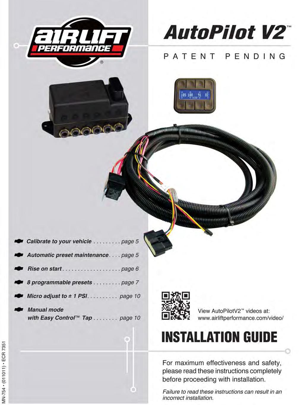
26 TABLE OF CONTENTS Installing the AutoPilot V2 Kit... 3 Setup and Calibration Troubleshooting Guide Program Presets Use the System Electrical Schematic Warranty and Returns Policy Replacement Information Contact Information NPT Assembly Instructions Manifold Template AutoPilot V2 Remote Control Unit Compressor Template
27 Installing the AutoPilot V2 Kit INSTALL COMPONENTS (SEE FIGURE 17, PAGES 8-9) 1. Layout: Plan component location first. Prior to mounting components, check to make sure the electrical harness connections will reach the manifold and compressor, the compressor leader hose will reach the tank, and the plumbing will route cleanly through the vehicle. NOTE: Be sure to install all components as far as possible from any heat sources. Plan and prepare harness and plumbing routing thru the vehicle: eliminate all sharp edges that could chafe, use grommets when passing through compartment walls. NOTE: If harness must be lengthened, use properly sized butt connectors and wire. If extending power/ground wires, use 8AWG wire minimum or contact Air Lift. NOTE: Air Compressors ingest moisture and will deposit it inside the tank. The AutoPilot V2 system does not include moisture separators or filters, and does require periodic tank moisture drain. If using an Engine Driven compressor, proper oil and water filtration must be added as these compressors will quickly contaminate the air suspension system. 2. Prepare and install: Compressor Prepare compressor intake: if inside vehicle, attach filter to port on end of compressor (Fig. 17). If compressor located outside vehicle, snorkel inlet filter to dry location inside vehicle. Center punch and drill four holes using the template on page 15. Attach using hardware supplied with compressor. Viair Max. Tank Pressure 380C C C C 150 Manifold Locate manifold above compressors and tank if possible to avoid compressor ingested water from gathering in manifold. 480C 175 Position manifold in desired location: make sure manifold mount surface is flat. Fasten using the two provided self-tapping screws. If mounting surface not flat, add washers to space the manifold up over surface irregularities. Tank pre assembly (see fig. 17) NOTE: compressors ingest moisture and will deposit water in the tank. Tanks must be regularly purged be sure to provide easy access to drain/fill valve (preferably outside the vehicle). Apply thread sealant as necessary. Determine tank location and orientation prior to installing fittings. In the lower most tank threaded port, install drain/fill PTC fitting. Choose a tank threaded port for the compressor fitting. Choose highest tank threaded port for manifold airline routing. Plug the remaining tank ports with hex plugs. Tank install (see fig. 17) Use tank feet as template, drill holes for hardware assembly. Attach tank using supplied hardware. Cut appropriate length of hose from the manifold port 5, to the PTC fitting on tank. Route drain/fill air line with schrader valve (preferably outside vehicle). NOTE: Use a standard hose cutter or razorblade. Cut all hose ends square and as smooth as possible. MN-754 3
28 INSTALL HARNESS 1. Disconnect battery ground while installing system. 2. Compressor / manifold connections (see fig. 17) Attach the manifold connector, it will click into place once fully seated. Push the tab on the connector to release and remove it. Mount the compressor relay in a preferred location using a self-tapping screw. NOTE: Use appropriate terminal crimp tool to ensure a good connection. Cut off the spade and eyelet from the compressor power and ground wires. Strip ¼ of wire casing from the compressor wires. Strip ¼ of wire casing from the black and pink harness wires. Using butt connector attach the RED compressor wire to the PINK harness wire. Using butt connector attach the BLACK compressor wire to the BLACK harness wire. Carefully apply heat (preferably with a heat gun) to seal these connections. The plastic casing on the butt splice will shrink and seal when heat is applied. 3. Battery / ignition connections (see fig. 17) Identify the power/ground + ignition leg of the harness. One 10AWG black wire, One 10AWG red wire, One 18AWG pink wire. Route power leg of the harness free from any heat source to the battery. Using Butt connector attach the red harness wire to a fuse holder. Attach a 3/8 eyelet to the other end of the fuse holder and attach to battery +. Attach a 3/8 eyelet to the black wire and attach to battery ground. Route the 18AWG pink wire to a key switched ignition source not accessory. Using Butt connector attach the pink ignition wire to a fuse holder. Select an auxiliary ignition source and attach the fused ignition wire. Use fuse adaptors as necessary. 4. Display Route display cable as desired to the preferred operating location. Attach the display cable to the main harness cable (small white 3 cavity connector). 5. Reconnect battery INSTALL AIR LINES NOTE: Use a standard hose cutter or razorblade. Cut all hose ends square and as smooth as possible. Route and attach air lines to air springs Route air lines free from abrasive edges and heat sources. Attach manifold port 1 to the front, drivers side spring FL (Front Left). Attach manifold port 2 to the front, passengers side spring FR (Front Right). Attach manifold port 3 to the rear, drivers side spring RL (Rear Left). Attach manifold port 4 to the rear, passengers side spring RR (Rear Right). Attach manifold port 5 to the PTC fitting previously installed on the tank. Manifold port 6 is the exhaust port. Port 6 can be left open, or routed to a preferred exhaust location. NOTE: Air lines should be pushed in firmly, with a slight back and forth rotational twist check connection by pulling on each line to verify robust connection. NOTE: Release the air line from the fitting by releasing air, pushing on the line, depressing the ring towards the fitting, and then pulling the hose out of the fitting. 4 MN-754
29 Setup and Calibration AutoPilot V2 is an advanced pressure-based air suspension control system, using state-of-the-art software algorithms to calibrate or map the control system to your vehicle. Once the system is calibrated, the algorithm predicts required valve open time to move the air suspension to achieve preset target pressures. AutoPilot V2 has 8 programmable presets, allowing the user to input 8 different combinations of the 4 corner air spring pressures. After installing AutoPilot V2 in your vehicle, please follow the steps below to properly setup your new system! If changes are made after installing and calibrating the system such as changes to air springs, lines, tank, compressor, or other vehicle modifications the system must be recalibrated. SYSTEM CALIBRATION AND SETTINGS 1. Key-on power up, compressor should come on to fill the tank. 2. Press buttons 1 and 5 at the same time (1+5) and hold for 5-10 seconds until settings and diagnostics mode main page appears (fig. 2). 3. Press button 1: TANK ADJUST. Set tank pressure preference by pressing MIN and MAX up/down buttons (fig. 3). Press buttons 1+5 to exit to settings and diagnostics mode. Calibrate to your vehicle NOTE: System will automatically deflate to 0 PSI and inflate to 100 PSI. 4. Press button 2 to enter CALIBRATE (fig. 4). Press SYSTEM CAL Button 1, follow instructions to calibrate AutoPilot V2 system to your vehicle. Once calibration is complete, Press buttons 1+5 to exit to settings and diagnostics mode. 5. Press button 3 to enter BACKLIGHT (fig. 5). Set display backlight to your preference by pressing the + and on R (Red), G (Green), B (Blue). Press buttons 1+5 to exit to settings and diagnostics mode. Automatic preset maintenance 6. Press button 4 to enter PRESET MAINTAIN (fig. 6). Press Button 8 to turn ON or OFF. When ON, this function actively monitors air spring pressure and will fill to maintain active preset pressure. If any corner requires 3 or more inflates, System will alert LEAK, displaying an L next to the suspect air spring pressure. NOTE: This function will not exhaust pressure. If air spring pressure is higher than preset target, only the operator pressing the preset button again will activate the system to exhaust air spring pressure (for safety). Press buttons 1+5 to exit. NOTE: PRESET MAINTAIN should be off for performance/ track driving or if operating in extremely hilly areas. FULL fig. 1 fig. 2 fig. 3 fig. 4 fig. 5 fig LF RF T LR RR MIN=145 Button Definition TANK ADJUST CALIBRATE BACKLIGHT PRESET MAIN BACKLIGHT R G ADJ B PRESET MAINTAIN? ON MAX=175 CALIBRATION MENU 1 SYSTEM CAL 2 ADJUST SYSTEM 3. SENSOR CAL MN-754 5
30 7. Press button 8 to toggle to settings page 2 (fig. 7). 8. Press button 5 to run a compressor test (fig. 8). This function will exhaust the tank to your specified MIN tank pressure, then turn ON the compressor and measure its inflate time to achieve MAX pressure. AutoPilot V2 will record this fill time, allowing the operator to compare future fill times to determine compressor performance. Press buttons 1+5 to exit. 9. Press button 6 to view the number of hours the compressor has been running. Rise on start 10. Press button 7 to enter RISE ON START (fig. 9). This function will automatically activate valves to achieve preset 1 target pressures when the vehicle is keyed-on. This function allows the operator to drive away seconds after vehicle is started. Press buttons 1+5 to exit. 11. Press button 8 to toggle between PSI and BAR pressure units and check software version. Press buttons 1+5 to exit. NOTE: BAR is actually DeciBar values. 12. Press buttons 1+5 to exit settings and diagnostics you are now ready to create presets! PRESSURE SENSOR CALIBRATION If the AutoPilot V2 system experiences a pressure reading that appears to be incorrect or if the Display instructs you that calibration is required (fig. 10), then please follow the procedure below. 1. Enter Settings Menu. 2. Select Calibration Menu (fig. 2). 3. Select Sensor Cal (fig. 4). 4. Follow the text on the display to calibrate the pressure sensors (figs. 10 & 11). a. You will be required to disconnect all the air lines from the manifold for the calibration process to complete. b. Once complete connect the air lines. fig. 7 fig. 8 fig. 9 fig. 10 fig. 11 fig Air Lift Performance COMP TEST COMP TIME RISE ON START PSI / BAR & SWV TANK PRESSURE RANGE PSI PROCEED? YES NO RISE ON START? ON PRESSURE SENSOR CAL REQUIRED PRESS ANY KEY TO CONTINUE WARNING!! SENSOR CAL WILL EXHAUST ALL PROCEED? YES NO CAL SUCCESSFUL PRESS ANY KEY TO CONTINUE 6 MN-754
31 Program Presets NOTE: Preset 1 should always be entered as the desired ride pressure for the RISE ON START function. 1. Determine ride pressures: press buttons 1+5 to toggle display to MANUAL MODE. Manually activate each corner (see MANUAL Mode section page 10) to achieve desired normal driving ride pressure. (fig. 13) 8 programmable presets fig LF RF T LR RR Button Definition 2. Program preset 1: press buttons 1+5 to toggle display to PRESET MODE. Press and hold button 1 to set 1: release button and actual air spring pressures will appear (fig. 11). Fine-tune the pressures by pressing up/down buttons. Press + hold to scroll. Press buttons 1+5 to exit. 3. You are now free to program the additional 7 presets to desired pressures. Typical presets can be: Low : set pressures to the lowest possible pressures for extreme low driving stance Front up : for speed bump or driveway clearance Rear up : for added load of passengers, equipment Play : for those that want to enjoy their air suspension freedom, AutoPilot V2 has a special function that recognizes side-side presets. When left side pressures are equal, and right side pressures are equal but >25psi different than left, the algorithm will activate side to side instead of front to back. It will also equalize all air spring pressures when exiting the play preset, conserving air by using the high pressure side to inflate the low pressure side. Pairing two play presets together allows side-side activation that consumes far less air than manual mode activation would consume (Figs. 15 & 16). Troubleshooting Guide PROBLEM Compressor doesn t run. fig. 13 fig. 14 fig. 15 fig EDIT PRESET 1 EDIT PRESET 6 EDIT PRESET 7 For further technical assistance please contact our customer service department by calling (800) , Monday through Friday, 8 a.m. to 8 p.m. Eastern Time. For calls from outside the USA or Canada, our local number is (517) CAUSE There is a blown fuse or relay, bad ground, or poor electrical connections. SOLUTION Replace the fuse, check the ground wire, or check the compressor connector. Compressor runs all the time. The compressor relay is defective or there is a leak. Replace the relay or locate the leak and repair. Air spring or tank leak. Fitting seal or air line compromised. Check to make sure air lines are seated in connectors. Inspect fittings with soapy water. Trim hose or re-seal fitting. Nothing happens when the vehicle is key-on ignition active. The display does not light up. There is a blown fuse or a poor connection. There is a blown fuse or a poor connection. Replace the fuses and check the electrical connections. Replace the fuses and check the electrical connections. Compressor runs all the time but no fill tank. Compressor inline check valve fitting has been overtorqued. Loosen fitting and check again. Replace if needed. System takes more than 4 iterations to achieve target pressure. Spring pressures are not zero when fully deflated. Calibration may need to be adjusted or system may need to be recalibrated. Pressure sensor calibration is off. Adjust ADJ value or Recalibrate system to reduce # of iterations. Recalibrate using Pressure Sensor Calibration Routine. MN-754 7
 3 AMP fuse Existing fuse Relay schematic reference To +12 Volt Battery Source 30 AMP Back View 30 ALOO2 Red 10GA Pink 20GA IGN 85 86 Gray 20GA To")
32 LF RF LR RR Air Lift Performance AL005 Butt connector AL AMP fuse AL004 Relay + Connect direct to battery fig. 17 Ignition Source (on while cranking) 3 AMP fuse Existing fuse Relay schematic reference To +12 Volt Battery Source 30 AMP Back View 30 ALOO2 Red 10GA Pink 20GA IGN Gray 20GA To Manifold 87 Compressor (OUT) (7) Pink 10GA 8 MN-754
 30 To +12 volt battery source Back View 30 30 AMP Red 10GA 85 86 85 86 Vehicle ground 87 Pink 20GA IGN Pink Gray 20GA 10GA To Compressor 2 To")
33 LEFT RIGHT Exhaust Drain/fill valve *mount in accessible location FRONT REAR For Reference Only Not included in kit For Reference Only Not included in kit LEFT RIGHT AL005 AL007 1/4 Elbow To add a second compressor Red 10GA 30 AMP Relay 2 (not included) 30 To +12 volt battery source Back View AMP Red 10GA Vehicle ground 87 Pink 20GA IGN Pink Gray 20GA 10GA To Compressor 2 To Manifold 87 To Compressor 1 NOTE: Air Lift recommends using a hose cutting tool to ensure a proper cut. If a hose connection has been disconnected the hose must be trimmed 1/2 back to provide for a leak free seal. Attach filter Pink 20GA IGN Pink 10GA MN-754 9
34 Use the System Air Lift Performance Now that your system is set up, it s time to use it. If changes are made after installing and calibrating the system such as changes to air springs, lines, tank, or compressor the system must be recalibrated. There are two modes: PRESET, and MANUAL. Pressing buttons 1and 5 together will toggle between modes. After 10 seconds of non-use, the display enters standby where the LCD dims. Any button hit will wake-up the display and allow users to activate the system. See mode operation below for more details. PRESET mode First button press will display the programmed preset. Users can quickly view each preset prior to activating to make sure they are selecting the desired preset. 2 nd button press of the same preset will activate it. The system will iterate up to 6 times to achieve the preset target pressures by +/- 3 psi. Display shows PLEASE WAIT as it iterates, then will flash SUCCESSFUL when achieved or UNSUCCESSFUL if not able to achieve the target pressure window. NOTE: if your system is not hitting Presets quickly, change the ADJ value. Enter Settings and Diagnostics mode (press Button 1+5 for more than 5 seconds), press #2 CALIBRATE, then ADJUST SYSTEM to toggle the value between 0 and 10; higher values increase system fill rates to overshoot target pressures. Micro adjust to ±1 PSI: If more accuracy is desired, double press the same preset and the system will refine pressures closer to target fig. 18 Preset Mode fig. 19 Manual Mode MANUAL mode MANUAL mode allows the user to fill or exhaust each spring. The display will show arrows above and below the pressures to indicate manual control mode. The arrow will be solid when the spring is filling / exhausting, and just an outline when not active. Manual mode with Easy Control Tap The system detects button press time. For a very short (<0.1sec) duration press, the system will open the valves for a defined burst, changing pressure minimally so users can fine-tune their pressures. For a longer than 0.1 sec duration press, the valves open as long as you hold it down. If a button is held active the fill / exhaust will timeout after 10 seconds. Fill springs: buttons 1-4 Exhaust springs: buttons MN-754
35 Electrical Schematic fig. 20 MN
36 Warranty and Returns Policy Air Lift Performance Air Lift Company warrants its performance products for one year to the original purchaser against manufacturing defects one year from the date of purchase when used on cars and trucks as specified under normal operating conditions. The warranty does not apply to products that have been improperly applied, improperly installed, or which have not been maintained in accordance with installation instructions furnished with all products. The consumer will be responsible for removing (labor charges) the defective product from the vehicle and returning it, transportation costs prepaid, to the dealer from which it was purchased or to Air Lift Company for verification. Air Lift will repair or replace, at its option, defective products or components. A minimum $10.00 shipping and handling charge will apply to all warranty claims. Before returning any defective product, you must call Air Lift at (800) in the U.S. and Canada (elsewhere, (517) ) for a Returned Materials Authorization (RMA) number. Returns to Air Lift can be sent to: Air Lift Company 2727 Snow Road Lansing, MI Product failures resulting from abnormal use or misuse are excluded from this warranty. The loss of use of the product, loss of time, inconvenience, commercial loss or consequential damages are not covered. The consumer is responsible for installation/reinstallation (labor charges) of the product. Air Lift Company reserves the right to change the design of any product without assuming any obligation to modify any product previously manufactured. This warranty gives you specific legal rights and you may also have other rights that may vary from state-to-state. Some states do not allow limitations on how long an implied warranty lasts or allow the exclusion or limitation of incidental or consequential damages. The above limitation or exclusion may not apply to you. There are no warranties, expressed or implied including any implied warranties of merchantability and fitness, which extend beyond this warranty period. There are no warranties that extend beyond the description on the face hereof. Seller disclaims the implied warranty of merchantability. Dated proof of purchase required. Replacement Information If you need replacement parts, contact the local dealer or call Air Lift customer service at (800) Most parts are immediately available and can be shipped the same day. Contact Air Lift Company customer service at (800) first if: Parts are missing from the kit. Technical assistance on installation or operation is needed. Broken or defective parts in the kit. Wrong parts in the kit. Have a warranty claim or question. Contact the retailer where the kit was purchased: If it is necessary to return or exchange the kit for any reason. If there is a problem with shipping, if shipped from the retailer. If there is a problem with the price. Contact Information If you have any questions, comments or need technical assistance contact our customer service department by calling (800) , Monday through Friday, 8 a.m. to 8 p.m. Eastern Time. For calls from outside the USA or Canada, our local number is (517) You may also contact customer service anytime by at techsupport@airliftperformance.com. For inquiries by mail, our address is PO Box 80167, Lansing, MI Our shipping address for returns is 2727 Snow Road, Lansing, MI You may also contact our sales team anytime by at sales@airliftperformance.com or on the web at 12 MN-754
37 NPT Assembly Instructions 1. Inspect port and fitting to ensure both are free of contaminants and excessive burrs and nicks. 2. Apply a stripe of liquid pipe sealant around the male threads leaving the first two threads uncovered. 3. Screw finger tight into the port. 4. Wrench tighten the fitting to the correct Turns Past Finger Tight position (see following table). CAUTION: NEVER BACK OFF AN INSTALLED PIPE FITTING TO ACHIEVE PROPER ALIGNMENT. LOOSENING INSTALLED PIPE FITTINGS WILL CORRUPT THE SEAL AND CONTRIBUTE TO LEAKAGE AND FAILURE. Torque Specifications Fitting Size Dash Size Turns Past Finger Tight Table 1 Torque ft/lbs 1/8 NPT /4 NPT /8 NPT /2 NPT /4 NPT NPT ¼ NPT ½ NPT NPT MN
38 Manifold Template Air Lift Performance AutoPilot V2 Remote Control Unit Top View Side View 14 MN-754
39 16380 Compressor Template HOLE PATTERN FOR BOTTOM OF COMPRESSOR MN
40 Need Help? Contact our customer service department by calling (800) , Monday through Friday, 8 a.m. to 8 p.m. Eastern Time. For calls from outside the USA or Canada, our local number is (517) Thank you for purchasing Air Lift Performance products! Air Lift Company 2727 Snow Road Lansing, MI or PO Box Lansing, MI Toll Free (800) Local (517) Fax (517) Printed in the USA

41 Kit Details HARDWARE LIST Part # Description Qty pt Fast Air Manifold - 1/ Gen 3 Display Electrical Harness - FastAir DOT 1/4 Air Line...2ft DOT Elbow 1/4PTC - 1/4PTC Fuse, spade 3amp Fuse, spade, 30amp ATC Fuse holder w/ cap GA Butt Connector GA Butt Connector GA Ring Terminal 3/ Female Spade Terminal GA Female Spade Terminal Adaptor, Mini Fuse...1 Part # Description Qty ATC/ATO Fuse Adaptor /2 MNPT X 1/4 FNPT /2 MNPT Center Sunk Hex Plug DOT Swivel Elbow 1/4Pipe - 1/4 PTC DOT Swivel Elbow 1/4MNPT-1/4PTC Push Lock Valve DOT 1/4 Air Line...50ft /4-14 X 1 Heavy Duty Washer /8 Flat Washer /8-16 x 1.25 Hex Cap Screw /8-16 Nyloc Nut Compressor (200 psi) Air Tank (5 gallon) Zip Tie...10 STOP! Missing or damaged parts? Call Air Lift customer service at (800) for a replacement part. MN-784
Air Lift. Kit PERFORMANCE INSTALLATION GUIDE Scion xb
 Air Lift PERFORMANCE Kit 75599 2008 Scion xb MN-687 (031111) ECR 7189 INSTALLATION GUIDE For maximum effectiveness and safety, please read these instructions completely before proceeding with installation.
Air Lift. Kit PERFORMANCE INSTALLATION GUIDE Scion xb
 Air Lift PERFORMANCE Kit 75699 2008- Scion xb MN-689 (041108) ECR 7072 INSTALLATION GUIDE For maximum effectiveness and safety, please read these instructions completely before proceeding with installation.
Air Lift. Kit Honda Prelude ( ) PERFORMANCE INSTALLATION GUIDE
 PERFORMANCE INSTALLATION GUIDE") Air Lift PERFORMANCE Kit 75532 Honda Prelude (1992-2001) Cover illustration may not depict actual kit. MN-542 (06708) ECR 6206 INSTALLATION GUIDE For maximum effectiveness and safety, please read these
Air Lift PERFORMANCE Kit 75532 Honda Prelude (1992-2001) Cover illustration may not depict actual kit. MN-542 (06708) ECR 6206 INSTALLATION GUIDE For maximum effectiveness and safety, please read these
Kit Details Air Lift Performance HARDWARE LIST STOP!
 Kit Details 27671 HARDWARE LIST Part # Description Qty 72605 4pt Fast Air Manifold - 1/4... 1 27042 Gen 3 Display... 1 26498-002 Electrical Harness - FastAir... 1 20946 DOT 1/4 Air Line...2ft 24672 Fuse,
Compressor Isolator Kit 50714
 Air Lift PERFORMANCE Compressor Isolator Kit 50714 MN-902 (011307) ERN 7261 Compressor not supplied with isolator kit. INSTALLATION GUIDE View AutoPilotV2 videos at: www.airliftperformance.com/video/ For
Kit INSTALLATION GUIDE. 160 psi Air Shock Controller
 Kit 25804 160 psi Air Shock Controller Cover image may not depict actual kit. MN-203 (121107) ECR 7119 INSTALLATION GUIDE For maximum effectiveness and safety, please read these instructions completely
92-00 Civic/ Integra/ Del Sol/ Accord/ CRX
 92-00 Civic/ 94-01 Integra/ 93-97 Del Sol/ 90-97 Accord/ 92-95 CRX Front Kit Part No. 75440 www.airliftperformance.com MN-513 (08409) NPR 4778 Please read these instructions completely before proceeding
Kit Details Air Lift Performance HARDWARE LIST STOP!
 Kit Details 27673 HARDWARE LIST Part # Description Qty 72605 4pt Fast Air Manifold - 1/4...1 27042 Gen 3 Display...1 26498-002 Electrical Harness - FastAir...1 20946 DOT 1/4 Air Line...60ft 24672 Fuse,
Air Lift. Kit PERFORMANCE INSTALLATION GUIDE. Scion tc. front application
 Air Lift PERFORMANCE Kit 75587 Scion tc front application MN-716 (031111) ECR 7189 INSTALLATION GUIDE For maximum effectiveness and safety, please read these instructions completely before proceeding with
92-00 Civic/ Integra/ Del Sol/ Accord/ CRX
 92-00 Civic/ 94-01 Integra/ 93-97 Del Sol/ 90-97 Accord/ 92-95 CRX Front Kit Part No. 75440 www.airliftperformance.com MN-513 (08409) NPR 4778 Please read these instructions completely before proceeding
Air Lift. Kit Dodge Charger, Challenger, 300C, and Magnum PERFORMANCE INSTALLATION GUIDE. (includes SRT 8 models, excludes AWD models)
") Air Lift PERFORMANCE Kit 75595 Dodge Charger, Challenger, 300C, and Magnum (includes SRT 8 models, excludes AWD models) MN-661 (031111) ECR 7189 INSTALLATION GUIDE For maximum effectiveness and safety,
Air Lift PERFORMANCE Kit 75595 Dodge Charger, Challenger, 300C, and Magnum (includes SRT 8 models, excludes AWD models) MN-661 (031111) ECR 7189 INSTALLATION GUIDE For maximum effectiveness and safety,
Kit INSTALLATION GUIDE. 5 psi Low Pressure Sensor (Single Gauge)
") Kit 25592 5 psi Low Pressure Sensor (Single Gauge) MN-333 (141404) ECR 7953 INSTALLATION GUIDE For maximum effectiveness and safety, please read these instructions completely before proceeding with installation.
Kit 25592 5 psi Low Pressure Sensor (Single Gauge) MN-333 (141404) ECR 7953 INSTALLATION GUIDE For maximum effectiveness and safety, please read these instructions completely before proceeding with installation.
Kit psi Low Pressure Sensor (Dual Gauge)
") Kit 25812 5 psi Low Pressure Sensor (Dual Gauge) MN-337 (111107) ECR 7119 INSTALLATION GUIDE For maximum effectiveness and safety, please read these instructions completely before proceeding with installation.
Kit 25812 5 psi Low Pressure Sensor (Dual Gauge) MN-337 (111107) ECR 7119 INSTALLATION GUIDE For maximum effectiveness and safety, please read these instructions completely before proceeding with installation.
Kit INSTALLATION GUIDE. 5 psi Low Pressure Sensor (Single Gauge)
") Kit 25592 5 psi Low Pressure Sensor (Single Gauge) MN-333 (131107) ECR 7119 INSTALLATION GUIDE For maximum effectiveness and safety, please read these instructions completely before proceeding with installation.
Kit 25592 5 psi Low Pressure Sensor (Single Gauge) MN-333 (131107) ECR 7119 INSTALLATION GUIDE For maximum effectiveness and safety, please read these instructions completely before proceeding with installation.
INSTALLATION GUIDE. Magnetic Height Sensor. No , 25430
 Magnetic Height Sensor No. 25415, 25430 MN-601 (11610) ECR 5863 INSTALLATION GUIDE For maximum effectiveness and safety, please read these instructions completely before proceeding with installation. Failure
Kit INSTALLATION GUIDE. Dodge 1500 Pickup 2 & 4WD. rear application
 Kit 52205 Dodge 1500 Pickup 2 & 4WD rear application MN-738 (011004) ERN 6877 INSTALLATION GUIDE For maximum effectiveness and safety, please read these instructions completely before proceeding with installation.
Air Lift. Kit PERFORMANCE INSTALLATION GUIDE. Chevy Cobalt, Chevy HHR. front application
 Air Lift PERFORMANCE Kit 75594 Chevy Cobalt, Chevy HHR front application MN-644 (031111) ECR 7189 INSTALLATION GUIDE For maximum effectiveness and safety, please read these instructions completely before
Kit INSTALLATION GUIDE. Front Application. Scion xa & xb
 Kit 75572 Scion xa & xb Front Application MN-610 (101710) ECR 8900 INSTALLATION GUIDE For maximum effectiveness and safety, please read these instructions completely before proceeding with installation.
Kit INSTALLATION GUIDE. Single Gauge Controller
 Kit 25655 Single Gauge Controller Cover image may not depict actual kit. MN-342 (031107) ECR 7119 INSTALLATION GUIDE For maximum effectiveness and safety, please read these instructions completely before
Air Lift. Kit MK IV Platform Slam front application PERFORMANCE INSTALLATION GUIDE
 Air Lift PERFORMANCE Kit 75518 MK IV Platform Slam front application NOTE: FOR USE ON VEHICLES WITH FRAME C-NOTCH MODIFICATIONS ONLY. FRONT SWAY BAR MUST BE REMOVED. (021111) ECR 7189 INSTALLATION GUIDE
No INSTALLATION GUIDE. For maximum effectiveness and safety, please read these instructions completely before proceeding with installation.
 No. 81560 MN-360 (071009) ECR 6976 INSTALLATION GUIDE For maximum effectiveness and safety, please read these instructions completely before proceeding with installation. Failure to read these instructions
Kit PERFORMANCE INSTALLATION GUIDE. Manual Air Management System
 MN-726 (041404) ECR 7825 Air Lift PERFORMANCE Kit 27666 Manual Air Management System INSTALLATION GUIDE For maximum effectiveness and safety, please read these instructions completely before proceeding
Air Lift Performance 2 MN-805
 2 MN-805 TABLE OF CONTENTS Introduction.... 2 Notation Explanation....2 Important Safety Notices...2 Installation Diagram.... 3 Hardware List....3 Tools List....3 Installing the Air Suspension.... 4 Preparing
Introduction Important Safety Notice...2 Notation Explanation...2. Hardware List...4. Attaching the Compressor...4. Wiring the System...
 LifeSTYLE Kits 27665/27666 Cover illustration may not depict actual kit. MN-726 (02002) ECR 684 INSTALLATION GUIDE For maximum effectiveness and safety, please read these instructions completely before
Kit INSTALLATION GUIDE. For maximum effectiveness and safety, please read these instructions completely before proceeding with installation.
 Kit 25690 MN-369 (111512) ECR 8349 INSTALLATION GUIDE For maximum effectiveness and safety, please read these instructions completely before proceeding with installation. Failure to read these instructions
Air Lift. Kit Ford Mustang (S-197) Track Pack Front Application PERFORMANCE INSTALLATION GUIDE
 Track Pack Front Application PERFORMANCE INSTALLATION GUIDE") Air Lift PERFORMANCE Kit 75523 Ford Mustang (S-197) Track Pack Front Application MN-813 (021402) ECR 7920 INSTALLATION GUIDE For maximum effectiveness and safety, please read these instructions completely
Air Lift PERFORMANCE Kit 75523 Ford Mustang (S-197) Track Pack Front Application MN-813 (021402) ECR 7920 INSTALLATION GUIDE For maximum effectiveness and safety, please read these instructions completely
Air Lift. Kit PERFORMANCE INSTALLATION GUIDE. Nissan Z33 350z & Infiniti G35. Front Application (except AWD)
") Air Lift PERFORMANCE Kit 75520 Nissan Z33 350z & Infiniti G35 Front Application (except AWD) MN-792 (031403) ECR 7931 INSTALLATION GUIDE For maximum effectiveness and safety, please read these instructions
Air Lift PERFORMANCE Kit 75520 Nissan Z33 350z & Infiniti G35 Front Application (except AWD) MN-792 (031403) ECR 7931 INSTALLATION GUIDE For maximum effectiveness and safety, please read these instructions
Kit INSTALLATION GUIDE. For maximum effectiveness and safety, please read these instructions completely before proceeding with installation.
 Kit 25801 MN-208 (121506) ECR 8243 INSTALLATION GUIDE For maximum effectiveness and safety, please read these instructions completely before proceeding with installation. Failure to read these instructions
Air Lift Performance 2 MN-896
 2 MN-896 TABLE OF CONTENTS Introduction....2 Notation Explanation...2 Important Safety Notices....2 Installation Diagram...3 Hardware List...3 Installing the Air Suspension.... 4 Preparing the Vehicle...4
Kit INSTALLATION GUIDE. Onboard Compressor Control System
 Kit 25572 Onboard Compressor Control System MN-516 (091801) ECR 8971 INSTALLATION GUIDE For maximum effectiveness and safety, please read these instructions completely before proceeding with installation.
Kit INSTALLATION GUIDE. Onboard Compressor Control System
 Kit 25690 Onboard Compressor Control System MN-369 (121801) ECR 8971 INSTALLATION GUIDE For maximum effectiveness and safety, please read these instructions completely before proceeding with installation.
Air Lift. Kit PERFORMANCE INSTALLATION GUIDE. MKII-III Platform. front application
 Air Lift PERFORMANCE Kit 75583 MKII-III Platform front application MN-733 (021106) ECR 7094 INSTALLATION GUIDE For maximum effectiveness and safety, please read these instructions completely before proceeding
Kits 52420, 52440, 52445, and 52465
 Universal Air Spring Spacer Kits 52420, 52440, 52445, 52460 and 52465 MN-1059 (011711) ERN 8773 Go to air-lift.co/liftspacer to determine which spacer is needed for your application. INSTALLATION GUIDE
WirelessAIR Advanced Integrated Remote
 Advanced Integrated Remote Kit 72000 Automatic Leveling Digital On-Board Compressor System MN-772 (011108) APQP 1313-31 INSTALLATION GUIDE For maximum effectiveness and safety, please read these instructions
Air Lift. Kits & PERFORMANCE INSTALLATION GUIDE. BMW E30 and E36/5/7/8 Compact. Rear Application
 Air Lift PERFORMANCE Kits 75673 & 78615 BMW E30 and E36/5/7/8 Compact Rear Application MN-889 (011406) ERN 7645 IMPORTANT: KIT 78615 DOES NOT COME WITH REAR SHOCKS. INSTALLATION GUIDE For maximum effectiveness
Installation Guide. Single Gauge Analog Kits 25850/ LoadCONTROLLER / Single
 LoadCONTROLLER / Single Single Gauge Analog Kits 25850/25854 * Image depicts kit with standard duty compressor MN-750 (11008) APQP 1312025 Installation Guide For maximum effectiveness and safety, please
Air Lift. Kit PERFORMANCE INSTALLATION GUIDE. Scion tc. front application
 Air Lift PERFORMANCE Kit 75587 Scion tc front application MN-716 (031111) ECR 7189 INSTALLATION GUIDE For maximum effectiveness and safety, please read these instructions completely before proceeding with
Air Lift Performance 2 MN-925
 2 MN-925 TABLE OF CONTENTS Introduction....2 Notation Explanation...2 Important Safety Notices....2 Installation Diagram...3 Hardware List...3 Installing the Air Suspension....4 Preparing the Vehicle...4
PERFORMANCE SUSPENSION PARTS
 PERFORMANCE SUSPENSION PARTS Introduction Air Lift Performance The purpose of this publication is to assist with the installation, maintenance and troubleshooting of this Audi A6 C5 Performance kit. It
Air Lift Performance 2 MN-886
 2 MN-886 TABLE OF CONTENTS Introduction....2 Notation Explanation...2 Important Safety Notices....2 Installation Diagram...3 Hardware List...3 Installing the Air Suspension....4 Preparing the Vehicle...4
Air Lift. Kit Volkswagen MKV & MKVI PERFORMANCE INSTALLATION GUIDE. Independent Rear Application
 Air Lift PERFORMANCE Kit 75690 Volkswagen MKV & MKVI Independent Rear Application MN-809 (031303) ECR 7578 INSTALLATION GUIDE For maximum effectiveness and safety, please read these instructions completely
Kit Details Air Lift Performance STOP! HARDWARE LIST
 Kit Details 27671 Air Lift Performance HARDWARE LIST Part # Description Qty 72605 4pt Fast Air Manifold - 1/4... 1 27042 Gen 3 Display... 1 26498-002 Electrical Harness - FastAir... 1 24672 Fuse, spade
Air Lift. Kit PERFORMANCE INSTALLATION GUIDE. Scion xa & xb
 Air Lift PERFORMANCE Kit 75572 Scion xa & xb MN-610 (091111) ECR 7189 INSTALLATION GUIDE For maximum effectiveness and safety, please read these instructions completely before proceeding with installation.
Kit INSTALLATION GUIDE. Mitsubishi EVO X Rear Application CAUTION
 Kit 78630 Mitsubishi EVO X Rear Application CAUTION READ PAGE 11 BEFORE INSTALLATION (021602) ECR 8402 INSTALLATION GUIDE For maximum effectiveness and safety, please read these instructions completely
Air Lift. Kit PERFORMANCE INSTALLATION GUIDE. Scion tc. front application
 Air Lift PERFORMANCE Kit 75587 Scion tc front application MN-716 (031111) ECR 7189 INSTALLATION GUIDE For maximum effectiveness and safety, please read these instructions completely before proceeding with
Kit 25415, Installation GuidE. Magnetic Height Sensor
 Kit 25415, 25430 Magnetic Height Sensor MN-601 (12701) ECR 5985 Installation GuidE For maximum effectiveness and safety, please read these instructions completely before proceeding with installation. Failure
Air Lift. Kit PERFORMANCE INSTALLATION GUIDE. Dodge Charger, Challenger, 300C, and Magnum. (includes SRT 8 models, excludes AWD models)
") Air Lift PERFORMANCE Kit 75595 Dodge Charger, Challenger, 300C, and Magnum (includes SRT 8 models, excludes AWD models) MN-661 (031111) ECR 7189 INSTALLATION GUIDE For maximum effectiveness and safety,
Air Lift PERFORMANCE Kit 75595 Dodge Charger, Challenger, 300C, and Magnum (includes SRT 8 models, excludes AWD models) MN-661 (031111) ECR 7189 INSTALLATION GUIDE For maximum effectiveness and safety,
Kits (53mm), (48.5mm)
, (48.5mm)") Kits 78570 (53mm), 78571 (48.5mm) Audi B9 Front Application MN-1073 (011808) ERN 8788 INSTALLATION GUIDE For maximum effectiveness and safety, please read these instructions completely before proceeding
Kits 78570 (53mm), 78571 (48.5mm) Audi B9 Front Application MN-1073 (011808) ERN 8788 INSTALLATION GUIDE For maximum effectiveness and safety, please read these instructions completely before proceeding
92-00 Civic/ Integra/ Del Sol/ Accord/ CRX
 92-00 Civic/ 94-01 Integra/ 93-97 Del Sol/ 90-97 Accord/ 92-95 CRX Front Kit Part No. 75440 www.airliftperformance.com MN-513 (08409) NPR 4778 Please read these instructions completely before proceeding
Air Lift Performance 2 MN-916
 2 MN-916 TABLE OF CONTENTS Introduction....2 Notation Explanation...2 Important Safety Notices....2 Installation Diagram...3 Hardware List...3 Installing the Air Suspension....4 Preparing the Vehicle...4
Air Lift. Kit MINI Cooper R50/52/53 PERFORMANCE INSTALLATION GUIDE. Rear Application CAUTION
 Air Lift PERFORMANCE Kit 78604 MINI Cooper R50/52/53 Rear Application CAUTION SEE PAGE 12 BEFORE BEGINNNING INSTALLATION (011505) ERN 7699 INSTALLATION GUIDE For maximum effectiveness and safety, please
Driver Side Shown P/N Figure 1
 P/N 59544 by MN-612 (05606) ECR 5714 Please read these instructions completely before proceeding with the installation. NOTE: Unbolt the lower bracket from the leaf spring if the vehicle is to be serviced
LifeSTYLE. Kit InstallatIon GuIdE. Scion tc. rear application
 LifeSTYLE Kit 75687 Scion tc rear application MN-717 (01905) ERN 6606 InstallatIon GuIdE For maximum effectiveness and safety, please read these instructions completely before proceeding with installation.
92-00 Civic/ Integra/ Del Sol/ Accord/ CRX
 92-00 Civic/ 94-01 Integra/ 93-97 Del Sol/ 90-97 Accord/ 92-95 CRX Front Kit Part No. 75440 www.airliftperformance.com MN-513 (08409) NPR 4778 Please read these instructions completely before proceeding
Air Lift. Kit Honda Civic (8th GEN) PERFORMANCE INSTALLATION GUIDE. Front Application
 PERFORMANCE INSTALLATION GUIDE. Front Application") Air Lift PERFORMANCE Kit 78524 Honda Civic (8th GEN) Front Application MN-950 (011503) ERN 8128 INSTALLATION GUIDE For maximum effectiveness and safety, please read these instructions completely before
Air Lift PERFORMANCE Kit 78524 Honda Civic (8th GEN) Front Application MN-950 (011503) ERN 8128 INSTALLATION GUIDE For maximum effectiveness and safety, please read these instructions completely before
Air Lift. Kit PERFORMANCE INSTALLATION GUIDE. Audi A6 C5 Platform. Front Application
 Air Lift PERFORMANCE Kit 75528 Audi A6 C5 Platform Front Application MN-915 (011311) ERN 7602 INSTALLATION GUIDE For maximum effectiveness and safety, please read these instructions completely before proceeding
Kit Installation Guide. Automatic Leveling Digital On-Board Compressor System
 Kit 72000 Automatic Leveling Digital On-Board Compressor System MN-681 (03806) ECR 6425 Installation Guide For maximum effectiveness and safety, please read these instructions completely before proceeding
Air Lift Performance 2 MN-803
 2 MN-803 TABLE OF CONTENTS Introduction.... 2 Notation Explanation....2 Important Safety Notices...2 Installation Diagram.... 3 Hardware List....3 Tools List....3 Installing the Air Suspension.... 4 Preparing
Air Lift MN-739
 Kit 60823 2008- Scion xb Cover illustration may not depict actual kit. MN-739 (011005) ERN 6893 INSTALLATION GUIDE For maximum effectiveness and safety, please read these instructions completely before
Kits and Dual Gauge Analog Compressor Systems
 LoadCONTROLLER / Dual Kits 25852 and 25856 Dual Gauge Analog Compressor Systems Kit #25852 with standard duty compressor Kit #25856 with heavy duty compressor MN-746 (041202) ECR 7259 INSTALLATION GUIDE
Kits 25490, Automatic Self-Leveling System
 II Kits 25490, 25491 Automatic Self-Leveling System 3 Y fuse For mini (ATM) fuse doubles (011608) ECR 8403 ORDER OF INSTALLATON height 1. Install electronic magnet sensor and bracket. r and 2. Install
Air Lift Performance 2 MN-919
 2 MN-919 TABLE OF CONTENTS Introduction....2 Notation Explanation...2 Important Safety Notices....2 Installation Diagram...3 Hardware List...3 Installing the Air Suspension....4 Preparing the Vehicle...4
Kit INSTALLATION GUIDE. Dodge 1500 Pickup, 2 & 4WD
 Kit 60818 Dodge 1500 Pickup, 2 & 4WD MN-753 (011012) ECR 6902 INSTALLATION GUIDE For maximum effectiveness and safety, please read these instructions completely before proceeding with installation. Failure
Air Lift. Kit Honda Accord (8th GEN) Acura TL & TSX PERFORMANCE INSTALLATION GUIDE. Front Application CAUTION
 Acura TL & TSX PERFORMANCE INSTALLATION GUIDE. Front Application CAUTION") Air Lift PERFORMANCE Kit 78520 Honda Accord (8th GEN) Acura TL & TSX Front Application CAUTION READ PAGE 8 BEFORE INSTALLATION MN-935 (021503) ECR 8209 INSTALLATION GUIDE For maximum effectiveness and
Air Lift PERFORMANCE Kit 78520 Honda Accord (8th GEN) Acura TL & TSX Front Application CAUTION READ PAGE 8 BEFORE INSTALLATION MN-935 (021503) ECR 8209 INSTALLATION GUIDE For maximum effectiveness and
Kits (with shocks), (no shocks) Audi B9
, (no shocks) Audi B9") Kits 78670 (with shocks), 78671 (no shocks) Audi B9 Rear Application MN-1074 (011808) ERN 8788 INSTALLATION GUIDE For maximum effectiveness and safety, please read these instructions completely before
Kits 78670 (with shocks), 78671 (no shocks) Audi B9 Rear Application MN-1074 (011808) ERN 8788 INSTALLATION GUIDE For maximum effectiveness and safety, please read these instructions completely before
Air Lift Performance 2 MN-903
 2 MN-903 TABLE OF CONTENTS Introduction....2 Notation Explanation... 2 Important Safety Notices.... 2 Installation Diagram...3 Hardware List... 3 Installing the Air Suspension....4 Preparing the Vehicle...
Neon Front Kit Part No
 EASYSTREET 1995-1999 Neon Front Kit Part No. 75588 www.airliftcompany.com MN-551 (07503) ECR 5014 Please read these instructions completely before proceeding with installation Warranty Information 1. All
Kit INSTALLATION GUIDE. Manual Air Management System. Front Application
 Kit 27666 Manual Air Management System Front Application MN-726 (071602) ECR 8332 INSTALLATION GUIDE For maximum effectiveness and safety, please read these instructions completely before proceeding with
Kit INSTALLATION GUIDE. Dual Gauge Controller
 Kit 25651 Dual Gauge Controller MN-362 (171107) ECR 7119 INSTALLATION GUIDE For maximum effectiveness and safety, please read these instructions completely before proceeding with installation. Failure
Air Lift. Kit Ford Mustang S550 PERFORMANCE INSTALLATION GUIDE. Rear Application
 Air Lift PERFORMANCE Kit 78621 Ford Mustang S550 Rear Application MN-938 (021505) ERN 8031 INSTALLATION GUIDE For maximum effectiveness and safety, please read these instructions completely before proceeding
Air Lift. Kit Volkswagen MKVII PERFORMANCE INSTALLATION GUIDE. Front Application
 Air Lift PERFORMANCE Kit 78522 Volkswagen MKVII Front Application (for vehicles with 55mm lower strut diameter) (011411) ERN 8035 INSTALLATION GUIDE For maximum effectiveness and safety, please read these
Air Lift Performance 2 MN-868
 2 MN-868 TABLE OF CONTENTS Introduction.... 2 Notation Explanation...2 Important Safety Notices....2 Installation Diagram.... 3 Hardware List....3 Tools List....3 Installing the Air Suspension.... 4 Preparing
WirelessONE. Kit INSTALLATION GUIDE. Key Fob Activated Compressor System
 MN-751 (081407) ECR 8016 WirelessONE Kit 25870 Key Fob Activated Compressor System INSTALLATION GUIDE For maximum effectiveness and safety, please read these instructions completely before proceeding with
Air Lift Performance 2 MN-915
 2 MN-915 TABLE OF CONTENTS Introduction....2 Notation Explanation...2 Important Safety Notices....2 Installation Diagram...3 Hardware List...3 Installing the Air Suspension....4 Preparing the Vehicle...4
Air Lift Performance 2 MN-886
 2 MN-886 TABLE OF CONTENTS Introduction....2 Notation Explanation...2 Important Safety Notices....2 Installation Diagram...3 Hardware List...3 Installing the Air Suspension....4 Preparing the Vehicle...4
Air Lift. Kit Ford Mustang (S-197) Track Pack Rear Application PERFORMANCE INSTALLATION GUIDE
 Track Pack Rear Application PERFORMANCE INSTALLATION GUIDE") Air Lift PERFORMANCE Kit 75623 Ford Mustang (S-197) Track Pack Rear Application MN-814 (011209) ERN 7403 INSTALLATION GUIDE For maximum effectiveness and safety, please read these instructions completely
Air Lift PERFORMANCE Kit 75623 Ford Mustang (S-197) Track Pack Rear Application MN-814 (011209) ERN 7403 INSTALLATION GUIDE For maximum effectiveness and safety, please read these instructions completely
Air Lift Performance 2 MN-904
 2 MN-904 TABLE OF CONTENTS Introduction....2 Notation Explanation... 2 Important Safety Notices.... 2 Installation Diagram...3 Hardware List... 3 Installing the Air Suspension....4 Preparing the Vehicle...
Air Lift Performance 2 MN-919
 2 MN-919 TABLE OF CONTENTS Introduction....2 Notation Explanation...2 Important Safety Notices....2 Installation Diagram...3 Hardware List...3 Installing the Air Suspension....4 Preparing the Vehicle...4
Air Lift Performance 2 MN-792
 2 MN-792 TABLE OF CONTENTS Introduction.... 2 Notation Explanation....2 Important Safety Notices...2 Installation Diagram... 3 Hardware List...3 Installing the Air Suspension.... 4 Preparing the Vehicle...4
Air Lift. Kit Ford Mustang S550 PERFORMANCE INSTALLATION GUIDE. Front Application
 Air Lift PERFORMANCE Kit 78521 Ford Mustang S550 Front Application MN-937 (011504) ERN 8031 INSTALLATION GUIDE For maximum effectiveness and safety, please read these instructions completely before proceeding
Air Lift PERFORMANCE INSTALLATION GUIDE. Front Application for Subaru Impreza, WRX & STi. ( ): Kits & 75552
: Kits & 75552") Air Lift PERFORMANCE (2002-2007): Kits 75551 & 75552 (2008-2012): Kits 75554, 75556 Front Application for Subaru Impreza, WRX & STi MN-790 (021311) ERN 7445 INSTALLATION GUIDE For maximum effectiveness
Air Lift PERFORMANCE (2002-2007): Kits 75551 & 75552 (2008-2012): Kits 75554, 75556 Front Application for Subaru Impreza, WRX & STi MN-790 (021311) ERN 7445 INSTALLATION GUIDE For maximum effectiveness
Air Lift. Kit Honda Civic (9th GEN) PERFORMANCE INSTALLATION GUIDE. Front Application
 PERFORMANCE INSTALLATION GUIDE. Front Application") Air Lift PERFORMANCE Kit 78526 Honda Civic (9th GEN) Front Application MN-952 (011502) ERN 8121 INSTALLATION GUIDE For maximum effectiveness and safety, please read these instructions completely before
Air Lift PERFORMANCE Kit 78526 Honda Civic (9th GEN) Front Application MN-952 (011502) ERN 8121 INSTALLATION GUIDE For maximum effectiveness and safety, please read these instructions completely before
Air Lift. Kit PERFORMANCE INSTALLATION GUIDE. MK IV Platform. Slam Front Application
 Air Lift PERFORMANCE Kit 75518 MK IV Platform Slam Front Application NOTE: FOR USE ON VEHICLES WITH FRAME C-NOTCH MODIFICATIONS ONLY. FRONT SWAY BAR MUST BE REMOVED. MN-756 (031409) ECR 8044 INSTALLATION
Air Lift. Kit Honda Accord (8th GEN) Acura TL & TSX PERFORMANCE INSTALLATION GUIDE. Rear Application
 Acura TL & TSX PERFORMANCE INSTALLATION GUIDE. Rear Application") Air Lift PERFORMANCE Kit 78620 Honda Accord (8th GEN) Acura TL & TSX Rear Application MN-936 (021503) ECR 8209 INSTALLATION GUIDE For maximum effectiveness and safety, please read these instructions completely
Air Lift PERFORMANCE Kit 78620 Honda Accord (8th GEN) Acura TL & TSX Rear Application MN-936 (021503) ECR 8209 INSTALLATION GUIDE For maximum effectiveness and safety, please read these instructions completely
WirelessONE. Kit Key Fob-Activated Compressor System INSTALLATION GUIDE
 Kit 25870 Key Fob-Activated Compressor System MN-751 (101710) ECR 8900 INSTALLATION GUIDE For maximum effectiveness and safety, please read these instructions completely before proceeding with installation.
Kit INSTALLATION GUIDE. Manual Air Management System
 Kit 27666 Manual Air Management System MN-726 (091606) ECR 8450 INSTALLATION GUIDE For maximum effectiveness and safety, please read these instructions completely before proceeding with installation. Failure
Air Lift. Kit BMW E30 (excludes AWD and M3) Front Application PERFORMANCE INSTALLATION GUIDE
 Front Application PERFORMANCE INSTALLATION GUIDE") Air Lift PERFORMANCE Kit 75573 BMW E30 (excludes AWD and M3) Front Application MN-888 (011406) ERN 7645 INSTALLATION GUIDE For maximum effectiveness and safety, please read these instructions completely
Air Lift PERFORMANCE Kit 75573 BMW E30 (excludes AWD and M3) Front Application MN-888 (011406) ERN 7645 INSTALLATION GUIDE For maximum effectiveness and safety, please read these instructions completely
Air Lift Performance 2 MN-803
 2 MN-803 TABLE OF CONTENTS Introduction.... 2 Notation Explanation....2 Important Safety Notices...2 Installation Diagram... 3 Hardware List...3 Tools List....3 Installing the Air Suspension.... 4 Preparing
Kit Installation Guide. Automatic Leveling Digital On-Board Compressor System
 Kit 72000 Automatic Leveling Digital On-Board Compressor System MN-681 (05902) ECR 6629 Installation Guide For maximum effectiveness and safety, please read these instructions completely before proceeding
LifeSTYLE. Kit Installation GuidE. Audi A4 B6/B7 Platform. rear application
 LifeSTYLE Kit 75678 Audi A4 B6/B7 Platform rear application MN-760 (011104) ERN 7059 Installation GuidE For maximum effectiveness and safety, please read these instructions completely before proceeding
Air Lift. Kit Honda Civic (8th GEN) PERFORMANCE INSTALLATION GUIDE. Front Application
 PERFORMANCE INSTALLATION GUIDE. Front Application") Air Lift PERFORMANCE Kit 78524 Honda Civic (8th GEN) Front Application INSTALLATION GUIDE PERFORMANCE SUSPENSION PARTS For maximum effectiveness and safety, please read these instructions completely before
Air Lift PERFORMANCE Kit 78524 Honda Civic (8th GEN) Front Application INSTALLATION GUIDE PERFORMANCE SUSPENSION PARTS For maximum effectiveness and safety, please read these instructions completely before
Kit No INSTALLATION GUIDE
 Kit No. 57105 Cover illustration may not depict actual kit. MN-388 (051210) ECR 7430 INSTALLATION GUIDE For maximum effectiveness and safety, please read these instructions completely before proceeding
Air Lift. Kit BMW E30 (excludes AWD and M3) Front Application PERFORMANCE INSTALLATION GUIDE
 Front Application PERFORMANCE INSTALLATION GUIDE") Air Lift PERFORMANCE Kit 75573 BMW E30 (excludes AWD and M3) Front Application MN-888 (011406) ERN 7645 INSTALLATION GUIDE For maximum effectiveness and safety, please read these instructions completely
Air Lift PERFORMANCE Kit 75573 BMW E30 (excludes AWD and M3) Front Application MN-888 (011406) ERN 7645 INSTALLATION GUIDE For maximum effectiveness and safety, please read these instructions completely
Air Lift. Kit PERFORMANCE INSTALLATION GUIDE. Audi A4/S4 Quattro B5 Platform front application
 Air Lift PERFORMANCE Kit 75555 Audi A4/S4 Quattro B5 Platform front application MN-766 (021402) ERN 8190 INSTALLATION GUIDE For maximum effectiveness and safety, please read these instructions completely
Air Lift. Kit & Universal Sleeve-Over-Shocks PERFORMANCE INSTALLATION GUIDE NOTE: THIS KIT IS SOLD WITHOUT A WARRANTY.
 Air Lift PERFORMANCE Kit 75566 & 75569 Universal Sleeve-Over-Shocks MN-749 (031111) ECR 7189 NOTE: THIS KIT IS SOLD WITHOUT A WARRANTY. INSTALLATION GUIDE For maximum effectiveness and safety, please read
Air Lift. AutoPilot V2 PERFORMANCE INSTALLATION GUIDE
 Air Lift PERFORMANCE AutoPilot V2 P A T E N T P E N D I N G MN-754 061404 ECR 7935 INSTALLATION GUIDE For maximum effectiveness and safety, please read these instructions completely before proceeding with
I. Preparing the Vehicle
 Multiple Applications See special notes for your particular vehicle. I. Preparing the Vehicle by MN-169 (11809) ECR 6529 NOTE For Toyota Sequoias: Before proceeding with the installation, measure up 6.75
Air Lift. Kit Honda Civic (8th GEN) PERFORMANCE INSTALLATION GUIDE. Front Application
 PERFORMANCE INSTALLATION GUIDE. Front Application") Air Lift PERFORMANCE Kit 78524 Honda Civic (8th GEN) Front Application MN-950 (011503) ERN 8128 INSTALLATION GUIDE For maximum effectiveness and safety, please read these instructions completely before
Air Lift PERFORMANCE Kit 78524 Honda Civic (8th GEN) Front Application MN-950 (011503) ERN 8128 INSTALLATION GUIDE For maximum effectiveness and safety, please read these instructions completely before
Air Lift Performance 2 MN-903
 2 MN-903 TABLE OF CONTENTS Introduction....2 Notation Explanation... 2 Important Safety Notices.... 2 Installation Diagram...3 Hardware List... 3 Installing the Air Suspension....4 Preparing the Vehicle...
Kit PSI Air Shock Controller
 Kit 25804 160 PSI Air Shock Controller MN-203 (141606) ECR 8612 INSTALLATION GUIDE For maximum effectiveness and safety, please read these instructions completely before proceeding with installation. Failure