Sept. 28, C. R. Jack 2,094,173 FREIGHT CAR AIR BRAKE. Filed May 9, Sheets-Sheet 1 ENE. - zne. s S. (2//7, 72a A % 7%.
|
|
|
- Ronald Chase
- 5 years ago
- Views:
Transcription
1 Sept. 28, C. R. Jack 2,094,173 FREIGHT CAR AIR BRAKE Filed May 9, Sheets-Sheet 1 s ENE - zne %N s S (2//7, 72a A % 7%.
2 Sept. 28, c. R. JACK FREIGHT CAR AIR BRAKE Filed May 9, Sheets-Sheet 2 ºzzzzzzz 479 Ø SSSSSSSSSSSSSS? Ø ae INESS
3
4

5 Patented Sept. 28, ,094,173 O UNITED STATES PATENT office... The principal object of my invention is to com bine, or incorporate, with what is generally known as type K of railway freight car brake equip ment-for example K2 triple valve-a, means causing the triple valve to perform its functions more dependably, irrespective of the greater present-day length of freight trains, and under all the varying train handling conditions. This application is in part a continuation of my co-pending application, Serial No. 693,9, filed October 14, 1933, entitled Air brake system. My auxiliary control means may be used in combination with one of the said standard K type of triple valves; this combination is, how ever, merely for convenience...so that the present system of railway freight car. equipment may be continued in use; but my improvement may also be embodied in some other suitable type of valve, so as to form therewith a single device. The brakes of a long freight train are applied serially by the K triple valves from the head to 2,094, FREIGHT CAR AIR BRAKE Carl R. Jack, Portland, Oreg, assignor to Inter s national Air Brake Control Company, Portland, Oreg, a corporation of Oregon. Application May 9, 1936, Serial No. 78, Claims. (C. 3-3) the rear of the train. With the present standard K2 triple valve in freight cár equipment, the fall 2. of pressure in the brake pipe of the cars remote from the locomotive, in a long train, may not be of sufficient rate to actuate the triple valves so as to apply the brakes at the rear end of a long train in unison with those of the freight cars. nearest the locomotive. Furthermore, if the fall of pressure is too slow to actuate the triple valves, as may be the case near the rear of long trains, the fall of pressure. may be insufficient to close the charging feeding groove of the triple valve, which would permit 3 pressure, to bleed thru, the latter, from the aux iliary reservoir of the triple valve into the brake pipe, thus tending to retard further the reduction of brake pipe pressure. The slide valve and piston of the K2 triple valve must be placed in applied position before a local quick service re duction in brake pipe pressure can be initiated. The special purpose of my invention is to pro vide a quick service feature which is entirely in 4 ' dependent of the operation of the triple valve it self; a further special purpose of my invention is to cause efficient propagation of the quick serv ice brake pipe-reduction towards the rear of the train in advance of the actual applications of the 0 brakes of the cars. I attain the objects of my invention by provid ing a supplemental reservoir in combination with the K2 triple valve, which supplemental reservoir 'is charged from the auxiliary reservoir of the K2 triple valve, and the pressure in the supplemental reservoir is held at the initial pressure of the air brake system. The supplemental reservoir pres Sure, according to my invention, is applied to ac tuate a diaphragm (or piston) operated valve in the auxiliary control feature of my invention, thereby causing the rapid reduction by dispersion of the brake pipe pressure Heretofore devices including a diaphragm-con trolled valve have been used, but such valve was operated by the pressure in the auxiliary reservoir of the triple valve. Hence, in case of very slow reduction in the brake pipe pressure, as would be the case at the rear end of a long train, this diaphragm-controlled valve could not be depend ed upon to bring about a quick service pressure reduction... Such undesirable condition would arise if for any reason the pressure in the auxiliary reservoir of the triple valve should reduce with the brake pipe pressure before the said diaphragm-con trolled valve is operated, and thus not create sufficient differential of pressure to bring about quick service pressure reduction. In order to prevent undesired loss of brake pipe pressure, or an undesired brake application, the auxiliary control feature of my invention provides means for stabilizing said diaphragm-controlled valve, said means being so arranged that a cer tain amount of reduction of brake pipe pressure is necessary before said diaphragm-controlled valve will be operated. A further object of my invention is to provide means for dissipating possible: surges in the brake pipe pressure due to the termination of the pressure. initial This rapid object...i rate of reduction attain automatically of brake pipe by providing means for restricting the quick service reduction passage of the brake pipe before closing said passage, so that when the brake pipe pres sure has been reduced to a predetermined amount, there will be a gradual leveling off of the pressure in said brake pipe.... s -... Another object of my invention is to provide automatic means for reducing the quick service reduction in grade work, when the brake cylinder retainer is set to retain pressure. I attain this object by providing. a special dia phragm (or piston); operated valve, controlled by predetermined differential between pressures in brake pipe and the supplementary reservoir of my control. This valve is further adapted to be operated by brake cylinder pressure, when the brake pipe pressure has been reduced a predetermined amount below that of said supplementary reser voir pressure of my control, and the brake cv O

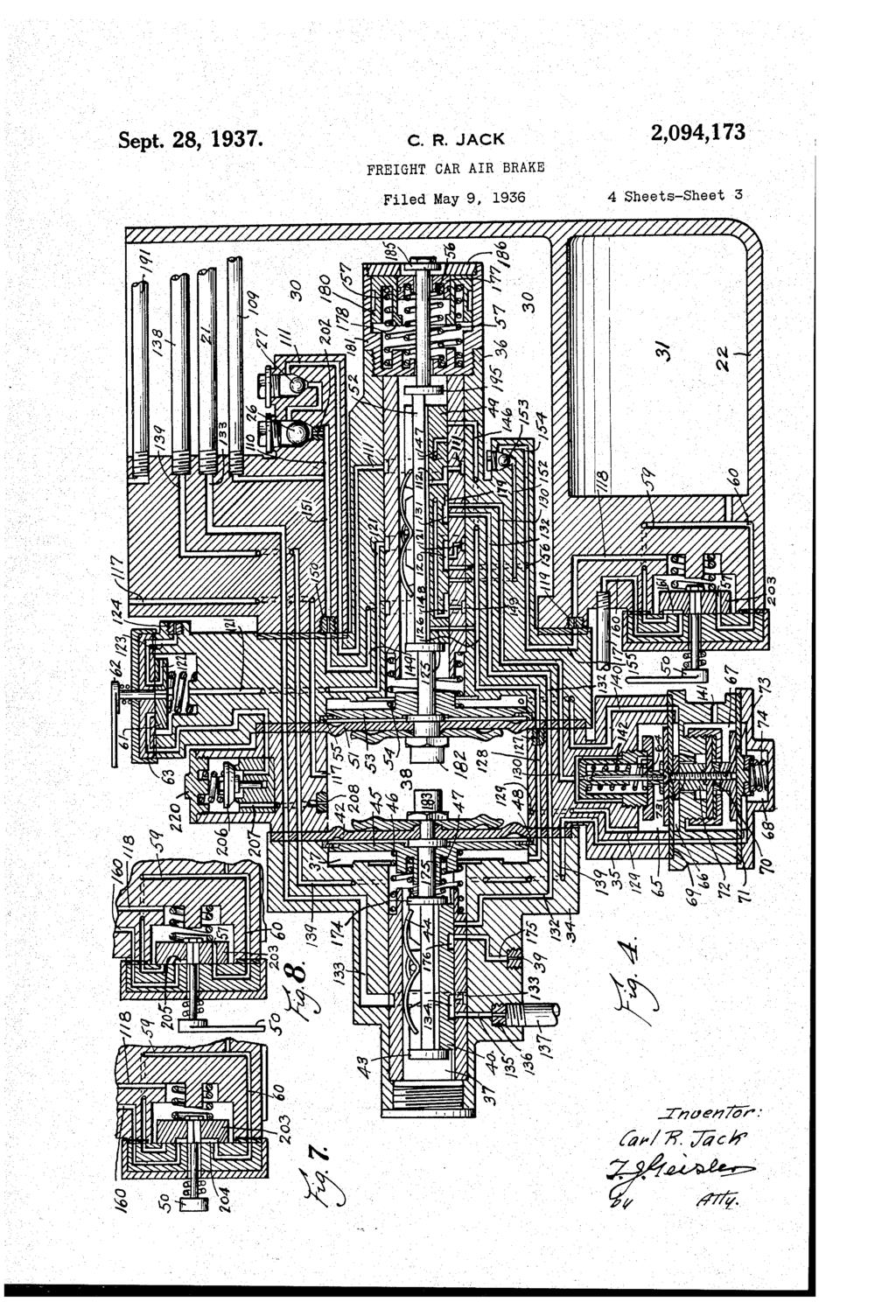
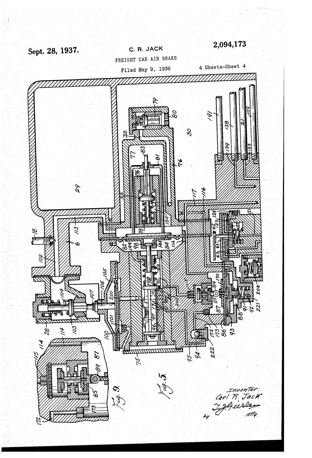
6 r O inder pressure has built up to a predetermined amount. Under the last mentioned conditions my said special valve functions to terminate fur ther duick Service brake pipe reduction. In case of grade work where the standard brake cylinder retainer is set to retain brake cylinder pressure, this retained pressure, when a service reduction is initiated, Will cause an early functioning of my said special valve to terminate further quick service reduction of brake pipe pressure. Another important object of my invention is to delay the application of the brake at the vicinity of the head end of the train, and so that the heavier the brake pipe reduction initiated the longer the application of the brakes at the head end of the train will be delayed. In case of come parative light brake pipe reduction it is not necessary to delay application of the brakes at the head of the train as long as in cases of heavy brake pipe service or emergency reduction. With the standard K2 triple valve equipment all the pressure for releasing the brakes or boost ing the brake pipe pressure, in releasing or charg ing the system, comes from the locomotive; hence, due to brake pipe friction, the rate of rise of pressure in the brake pipe in the vicinity of the rear of a long train is very slow, and may not insure a prompt movement of the triple valve piston to release position. With my special con trol a supplementary reservoir is charged to ini tial pressure during the charging of the brake, System, and retained at that pressure until a re lease is initiated. When the brake pipe pressure is raised slightly, as When release is initiated, this excess pressure stored in the supplementary res ervoir is carried to the brake pipe, thus rapidly propagating the initial rise of brake pipe pres sure towards the rear of the train irrespective of its length, hence insuring a quick and positive movement of all valves of the system to release position. In releasing following an emergency applica tion, it is usually necessary to increase the brake pipe pressure above that of the auxiliary reser voir emergency equalization pressure before the brake cylinder pressure can be released. There fore, a further purpose of my special control is to provide means for reducing the auxiliary res ervoir pressure after a recharge of the brake System has been initiated by the engineer. This object of my invention is accomplished by pro viding a supplemental reservoir charged to initial pressure during the charging of the brake sys tem, and retained at that pressure until a re lease is initiated. When the brake pipe pressure is raised slightly, as when release is initiated, this excess pressure, stored in the Supplemental reservoir, is carried to the brake pipe and the auxiliary reservoir is caused to be reduced in re charging of said supplemental reservoir. The above mentioned and other incidental fea-. tures of my invention are hereinafter fully de scribed with reference to the accompanying draw ings. In the drawings: Fig. 1 shows a side elevation of my auxiliary control feature connected to the brake cylinder and auxiliary reservoir of the so-called K2 triple Valve of a railway freight car air brake system; Fig.2 shows a fragmentary longitudinal verti cal section thru the brake cylinder, auxiliary reservoir, and the triple valve unit with my spe cial features incorporated therewith; in this fig 2,094,173 lure the elements of the triple valve unit are shown in released and charging position; Fig. 3 shows a similar fragmentary section in cluding, however, only the piston of the triple Valve unit, which in this figure has been moved into position to close the charging feed groove, and the diaphragm of my special feature devices controlling the piston is flexed to the left in re Sponse to differential pressure, thereby restrain ing the movement of the triple valve piston into application position; Fig. 4 shows a diagrammatic section on the line 4-4 of Fig. 1; Fig. shows a diagrammatic section on the line - of Fig. 1. It is to be noted that sections shown by Figs. 4 and, while on different planes, for convenience are assembled in the digram matic sections on a single plane; and certain parts shown in these sections, while actually not Within the plane of the sections, are included So as to make these sections diagrammatically complete. Furthermore, the lower part of Fig. Overlaps and duplicates the upper part of Fig. 4, as will be noted, so as to facilitate the connective reading of Figs. 4 and ; Fig. 6 is a larger scale fragmentary transverse Section of the check valves 3 and 32 on the line indicated by the arrow 6;. Figs. 7 and 8 show the manually controlled valve 3 in different positions than shown in Fig. 4, and Fig. 9 shows an enlarged section of check valve 8 which controls charging of accelerator reser 'Voir 29, said valve also being seen in Fig.. Referring to Figs. 1 and 2: The numeral represents the brake cylinder, 2 is the auxiliary reservoir, 3 the triple valve unit, is what I shall term the brake application delay portion of my special feature, or attach ment to the triple valve unit; is an adapter to facilitate the connection of my auxiliary control 6 to the auxiliary reservoir 2 and the brake cyl inder of the triple valve. The elements of the triple valve unit 3 are those common to the type K2 triple valves used on railway cars of freight trains. As apparent, these elements are shown in their release and charging position. It is to be noted that the usual cap of the triple valve 3 is removed, and is replaced by my said brake application delay portion 4; but the standard graduating stem 7 and Spring 8 of the triple valve unit 3 have been retained. My brake application delay portion 4 con prises two chambers 6a and 6b separated by a diaphragm 9. The triple valve side of this dia phragm 9 is connected to the brake pipe to by the usual passages. The diaphragm 9 carries a head 2 provided with plungers 3. The pur pose of this arrangement is to limit the move ment of the triple valve piston f 4, said plungers 3 normally being positioned as shown in Fig. 2. The chamber 6b on the other side of the dia phragm 9 constitutes a delay chamber, connected my auxiliary control 6 via passage 6 and pipe In addition to the above mentioned connec tions to my auxiliary control element 6, there is a connection 8 direct from the brake pipe O to my said auxiliary control element 6, as seen in Fig. 1. The brake cylinder retainer 9, which is usually connected to the exhaust passage of the triple valve unit 3 is connected to my auxiliary con trol element 6 via pipe 37. O

7 2,094,173 and from special reserv Valve 6 is manual sure The 3. slides in s One side-the left, side-of said diaphragm 82

8 () Ring 93 limits movement of said pressure plate 9 in the direction of said diaphragm 86. A reduction passage 9 is provided for cham ber 84 and controlled by check valve 94, which. valve prevents recharge of chamber 84 via re duction passage 9. In accelerator chamber 84 is incorporated an accelerator valve 96 held on its seat by Spring 97, and by the pressure in said chamber 84. Ac celerator valve 96 is connected to diaphragm 82 by sliding member or stem 98. Diaphragm 82 is longitudinally movable in the direction of ac celerator valve 96 without changing the position of the latter. Accelerator valve 96 is held in its normal position by spring 99. Accelerator valve 96 controls the connection from brake pipe to the cihamber 84 of this valve, also controls connection from Said, accelerator chamber 84 to actuator chamber 00. Accelera tor valve 96 in its normal position cuts off connec tion from said accelerator chamber 84 to the ac tuator chamber 00, and simultaneously re linquishes control of other connections. Said ac celerator valve 96 is so positioned by a Sufficient rate of reduction of brake pipe pressure in brake pipe reservoir 77 (governed by value of Spring re sistance 99 and size of duct 73) as to connect accelerator valve chamber 84 to actuator cham ber 100, and simultaneously cuts off other con 7 2,094,173 nections. Actuator chamber 00 is connected to atmosphere at all times via restricted orifice 0. The housing 28 is provided with auxiliary re duction outlet f O2 for brake pipe pressure. Walve 03 controls said reduction outlet 02, and is held on its seat by spring 04 thus closing said outlet. Actuator diaphragm 0 controls plunger 06, whereby a rapid rise in pressure in actuator chamber 100 forces said plunger. OS against shoulder Oil of valve 03 controlling auxiliary re duction outlet 02, thus unseating valve fo3 and opening outlet 02. Supplemental reservoir is provided with a manual release valve 90, see Fig. 1, which valve is connected to pipe 9? shown in Figs. 4 and, to permit manual release of the pressure in said supplemental reservoir. Assume all valves of my auxiliary control in normal position, and all units charged to initial normal system pressure as shown by Figs. 2 to, inclusive, the charging of all units of my in proved brake System is accomplished as follows: Charging Fluid pressure from train brake pipe enters chamber 6a to right of piston 4, see Fig. 2, via branch pipe connection fo. Piston 4 is posi tioned to the left, thus opening charging feed groove fos, permitting charging of auxiliary re servoir 2. While the auxiliary reservoir 2 is being charged, the supplemental reservoir is charged from said auxiliary reservoir 2 via pipe connec tion 09, passage 0, check valves 26 and 27, pas sage fif, and port f2 in resetting valve 49. Simultaneously, fluid pressure enters chamber 77 to right of diaphragm 82, from train pipe thru brake pipe O, pipe connection 8 and passage 3. Accelerator reservoir 29 is charged with brake pipe pressure from brake pipe chamber 77 via passages f4, chamber 87, duct and pas Sage 90. The charging rate of accelerator reser voir 29 is the same as the normal rate of rise of pressure in brake pipe chamber 77. Both sides of diaphragm 82 separating chambers 84 and 87 are charged at the same rate. Movement of dia phragm 2 towards the left is resisted by spring 78, hence, said diaphragm will remain in normal position while charging passage 90 is open. Fluid pressure from supplemental reservoir is trans mitted to the underside of diaphragm 86, via pas sage f6. Movement of diaphragm 86 downward is resisted by spring 92, and movement of spring 92 upward is limited by stop 93. The charging rate of supplemental reservoir via the auxiliary reservoir 2 agrees with the normal rate of rise of brake pipe pressure, hence diaphragm 86 will not be moved from normal position, shown in Fig., by a normal rate of rise in brake pipe pressure. Chamber 38 to left of diaphragm is charged from brake pipe pressure via passage 7 which connects with chamber 77. Pressure from sup plemental reservoir enters around stem 2 to right side of diaphragm 1. The charging rate Of Supplemental reservoir is the same as nor mal rate of rise of pressure in chamber 38; fur thermore, movement of diaphragm towards the right from normal position is resisted by Spring 4; hence diaphragm 1 and resetting valve 49 will not be moved from normal position by normal rate of rise in brake pipe pressure. In the normal position of resetting valve 49, special reservoir 3 f is connected to atmosphere via pas Sages, 7 and 8, duct 9, passages and f6, port, and passages f2?, 22, 23, and duct 24, hence elements of delay portion 4, see Fig. 2, controlled by pressure in said special reser voir 3 are rendered ineffective to influence oper ation of triple valve 3, in its release or application function. When resetting valve 49 is in normal position auxiliary chamber 37, to the left of dia phragm 42, is charged by pressure from supple mental reservoir via port f2, passage 26, duct 27 and passage 28; and, furthermore, po Sitioning of diaphragm 42 towards the left is re Sisted by spring 46, hence diaphragm 42 and its attached release valve will not be moved from normal position by a normal rate of rise in brake pipe pressure. Brake pipe pressure is connected to the under side of release valve via passage 29, chamber 6, supplemental valve 64 pas Sage, port 3? in resetting valve 49, and passage 32. When the triple valve 3 of the System is in release position pressure in brake cylinder is connected to atmosphere via usual exhaust passage, see Fig. ii; the pressure thus escaping via passages 2, 33, port 34 in said re lease valve, and passages 3, duct 36 and pipe 37. Chamber 68 under diaphragm 7 f is connected directly to brake cylinder pressure via passages 38 and 39. Brake pipe pressure is present above diaphragm 69 in chamber 6. Supplemental res ervoir pressure is connected to the under side of diaphragm 69 and the upper side of diaphragm 70 via passage. The under side of diaphragm 70 is connected to atmosphere via passage 4 i. Diaphragms 69 and 70 are connected together by Spacer 72. When there is no pressure in the System, Supplemental valve 64 will be held in up per position by Spring 74, thus closing passage, which helps to prevent unseating of release valve and of resetting valve 49, while the brake pipe pressure initially enters the system. Pressure from supplemental reservoir, acting on upper side of diaphragm 70 will return dia phragms 70 and 69 to normal position. Supple mental valve 64 is now returned to normal posi tion by Spring f42, thus connecting passages 29 and. In initiating release, or recharge, of brake sys tem, the engineer's automatic brake valve is usu O

9 2,094,178 ally in release position, in which position main Chamber 6b, Fig. 2, to right of diaphragm 9 is reservoir pressure, stored at locomotive, is con nected directly to train brake pipe via large port 6, 7,, 61,9 from special reservoir 3f. : opening in said automatic brake valve; thus the... Rise in brake pipepressure in chamber 6a above initial rate of rise in brake pipe pressure for normal charge of system may effect an undesired valves located near the locomotive is very rapid overcharge of auxiliary reservoir 2, so that when. as compared to the normal charging rate com brake pipe pressure is returned to normal pres Sure, the pressure in chamber. Sa may be reduced mon for valves located remote from locomotives. The effect of such rapid rise of brake pipe. press. below the pressure present in auxiliary reservoir :... 2, and thus cause an undesired movement of the sure in my improvement is as follows: A rapid rise of brake pipe pressure h. chamber '. piston f4 towards the right, thus placing it in application position, unless some means are pro-: 6a to right of triple valve piston'? 4, Fig. 2; will move said piston to extreme left, thus to its re vided for limiting such movement. With my, in tarded, recharge position. Charging of auxiliary vention this undesired action is prevented. Dia phragan 9 has a larger area than that of triple reservoir 2 is the same as explained for normal charging, except at a slower rate, via usual triple valve piston, f4, thus when brake pipe" pressure is reduced slightly below that of the pressure in... valve 3 restricted charging passage 43. auxiliary reservoir 2, plungers' f3, will be moved If the rapid rise in brake pipe pressure in chamber 87 on diaphragm 86, Fig., sufficiently towards the left, as shown in Fig. 3, thus limiting exceeds charging rate of supplemental reservoir travel of said piston 4 to position closing charg to compress spring 92, it will seat valve 8, ing feed groove 08. When brake pipe pressure close charging passage 90, and prevent overcharge has been increased above, pressure in auxiliary.reservoir 2, diaphragm 9 and piston 4, together. of small accelerator reservoir. 29. When charg ing passage 90 is open any excess pressure in res with members controlled by piston, 14, will be ervoir. 29 will rapidly equalize with brake pipe returned to normal position pressure via both charging passage 90 and re When pressures in brake pipei, and supple duction passage 9, and thus prevent deflection of : mental reservoir have: equalized, diaphragm. diaphragm 82 towards the left from normal posi * t, Fig. 4, will be returned to normal position by tion. Diaphragm support f84 is slotted to per : Spring resistance 4, but resetting valve 49 will mit longitudinal movement of diaphragm 82 to remain in extreme right position, since stem 2 wards the left from normal position without dis is permitted some...freelongitudinal movement turbing valve member 96. Sufficient rise in before contacting said resetting valve brake pipe pressure in chamber 77, at the right Sufficient rise of brake, pipe pressure in cham of diaphragm 82, above pressure in chamber 84, - ber 38 above pressure in auxiliary chamber 37 will move said diaphragm 82 to the extreme left, will move diaphragm 42 and therewith release thus, compressing spring 78 and unseating aux valve to extreme left, thus compressing spring iliary valve 33. Said sufficient amount of pres 46, in which position of release valve, the brake, sure is governed by value of spring 78. Brake. cylinder exhaust passage 33 via port 34 is closed. pipe pressure is now connected to top of check : Said sufficient amount of pressure is governed by i value of spring 46. When pressures, influencing. valve 9 via passage 32, this check valve prevent ing recharge of said supplemental reservoir, : diaphragm 42 have equalized, said diaphragm and via passage 32. While supplemental reservoir gattached-release, valve will be returned to nor is being recharged from auxiliary reservoir 2... mal position by spring 46.3% of system, excess brake pipe pressure will be ab Service application 4 sorbed in recharge of the brake system, thus ef fecting a return of diaphragm 86 to normal posi-. Assume as A that all valves are in normal position tion, and opening of charging passage 90 to per shown in Figs. 2 to, and that a service rate of. brake pipe. pressure reduction is initiated by... mit further charging of accelerator reservoir. 29. Diaphragm 82 and auxiliary valve 33 are reengineer as usual When chamber 6a, Fig. 2, is connected to... atmos.. 0 turned Sufficient to normal rise in position brake pipe by spring pressure 78. in cham-sphere, there will be no movement of diaphragm 9, ber 38 above pressure in supplemental reservoir. is and will compress spring 4, thus moving resetting: normal its position. attached members A reduction towards in brake the pipe left pres from valve 49 to its extreme right position; said suffi '..." sure, in chamber 6a, at a sufficient rate to effect. cient amount of pressure is governed by value. movement of triple valve piston: 4 towards the of spring 4. In this position of resetting valve. is right, will close charging feed groove 108, thus,, 49, connection from said supplemental reservoir. preventing reduction of auxiliary reservoir pres sure via said feed groove 08. When brake pipe to 'auxiliary chamber 37 is closed; and cham ber 37 is connected to auxiliary reservoir 2 via: pressure in chamber 6a, Fig. 2, has been reduced sufficiently below... that of pressure in auxiliary passage 28, duct 27, passages. 26, 46, and ports 47 and 48 in resetting valve 49, which reservoir 2, said triple: valve: piston 14, and at register with passage 49; thence thru duct 0, : tached valves f63 will be moved to the right, to passages.? and 109. Passages 32 and are full service or application position, in which posi registered by elongated port 3 in resetting tion pressure in said auxiliary reservoiris, con valve 49; also, elongated charging port if f 2 of. nected to brake cylinder of system via passage 6 resetting valve 49, which controls charging of 62 and usual ports in slide valve 63 of triple supplemental reservoir, registers with pas valve 3. While said triple valve piston 4 is being sage if f from auxiliary reservoir of the system; moved. into full service or application position, passage from special reservoir 3 to atmosphere. brake pipe pressure is momentarily connected to is closed, and the pressure in auxiliary reservoir. brake cylinder via usual quick service ports in ' 2 of system is connected to special reservoir. 3?. lide valves 63 of triple val via passage 149; elongated port 48, in resetting Check valves and 27, Fig. Sig. 4, prevent equaliza valve 49, which registers with passage 2, thence tion of pressure in said supplemental reservoir "with that of the auxiliary reservoir 2 via charging. via check valve? 3 and passages ,......,. ; duct "with passage t i? 0, of - supplemental reservoir. 19, passages 18, 7 and. 7 charged to normal system pressure via passages.. 7,

10 O When a brake pipe pressure reduction is ini tiated in chamber 8 above diaphragm 86, Fig., said diaphragm is deflected upward by retained supplemental reservoir pressure present in cham ber. 88, thus causing valve 8 to close charging. passage, 90 of accelerator reservoir 29. Brake pipe pressure in chamber 8 must be reduced slightly below the supplemental reservoir pres sure in chamber 88 due to natural resistance of diaphragm 86 and to weight of check valve 8 and pressure plate fo, before said diaphragm 86 is deflected upward from normal position, so that accelerator reservoir pressure may initially feed back into the brake pipe, via passages 90 and 9, thus preventing movement of valve 96 towards the right when a rapid rate of service reduction of brake pipe pressure is effected. When service rate of brake pipe pressure re duction is initiated in chamber 84, movement of diaphragm 82 towards the right from: normal position is resisted by spring 99; furthermore, pressure in accelerator reservoir. 29 is permitted to reduce with the brake pipe pressure in cham-. ber 77 via port? of accelerator valve 96, pas sage 9, check valve 94, passage f2, and duct 73, hence diaphragm 82 and valve 96 will remain. in normal position, as shown in Fig., unless the brake pipe reduction exceeds, its usual service rate of reduction. When the brake pipe pressure in chamber 38, Fig. 4, has reduced a Sufficient amount below the pressure in auxiliary pressure chamber 37, dia phragm 42 will be deflected to the right, thus compressing stabilizing spring 47 until shoulder 74 contacts with stop 7. Auxiliary pressure chamber 3 being connected to supplemental reservoir,, and the pressure in the latter be ing retained at initial pressure of the system by check valves 26 and 27, such movement of dia phragm 42 is therefore independent of any op eration of triple valve 3, or any loss of pressure in auxiliary reservoir 2. In this position of dia phragm 42 port 76 of release valve, passages 32 and 7 will register, thus effecting a dis persion of brake pipe pressure at a rapid rate via reduction passages 29,, larger port, 3 of resetting valve 49, and passages f32, port 76, passage 7 and duct 39, and simultaneously brake cylinder exhaust passage. 33 is closed by release valve. When the brake pipe pressure in chamber 38 has reduced a sufficient amount below that of the pressure in supplemental res ervoir, which sufficient amount is governed by the resistance of spring 6, diaphragm? will be deflected towards the left, thus compressing Spring 6 until shoulder TT contacts with stop 8, see Fig. 4. Diaphragm 42 is not restrained by Spring 46; the latter serves merely to restrain movement of diaphragm - 42 from normal to ex treme left position, in response to normal rate of increase in pressure in chamber 38. The Spring 47 is merely a stabilizing spring to pre vent undesired movement of diaphragm, 42 to wards the right from normal position, due to slight reduction of pressure in chamber 38 be low that in chamber 37. On the other hand, diaphragm is restrained in its movement to : its extreme left position in response to reduction of pressure in chamber 38 by spring 6, which has a much greater value than spring 47. Shoul der of stem 2 now has contacted with resetting Valve 49, thus positioning the resetting valve to wards the left, thereby closing Supplemental res ervoir charging passage ff?, and connection 2 2,094,178 from supplemental reservoir to auxiliary pres sure, chamber 3. Restricted port 79 of resetting valve 49 now registers with passage so that further dis persion of brake pipe pressure via passage 7 is at a slower rate. At the same time special reservoir 3 is con nected to atmosphere via elongated port of resetting valve 49, and port f48 of such valve registers with passage 26, thus connecting pres Sure in auxiliary reservoir 2 with auxiliary cham ber 37 via passage 1, duct 0, passage 49, port 48 in resetting valve 49, passage 26, duct 27, and passage 28. Restricted orifice or duct 27 controls rate of equalization of said pressures in auxiliary chamber 37 with auxiliary reservoir 2. Pressure in auxiliary chamber 37 in excess of that in auxiliary reservoir 2 tends to boost - the latter, thus increasing sensitivity of triple valve piston 4, Fig. 2, and promoting applica tion of brakes. A further service reduction in brake pipe pres sure in chamber 38 below that of retained pres sure in supplemental reservoir, sufficient to overcome resistance of spring 7, will deflect dia phragm., and therewith resetting valve 49 will be positioned to the extreme left, thus compress ing spring 7 until shoulder 80 contacts with stop f8 f. During such novement of diaphragm, mem ber 82 contacts with member 83, thus returning diaphragm 42 and release valve to normal position, and thus closing passage f32, if it has not been closed in advance of this movement by valve 64, and terminating further dispersion of brake pipe pressure thru duct 39. In the last mentioned position of resetting valve 49, passages 26 and 49 are still connected by elongated port 148 of said resetting valve, and passages f 6 and 2 are still connected by the elongated port of this valve.... Retained supplemental reservoir pressure in chamber 66 acting downward on diaphragm. To offers resistance to movement of diaphragm 69 upward; however, when the brake pipe pressure in chamber 6 is reduced a sufficient amount governed by the area of diaphragm 7 O-below the retained pressure in supplemental reservoir, diaphragms.69 and 70 will be deflected upward, thus seating supplemental valve 64, and closing brake pipe pressure reduction passage f, since chamber 66 is connected to Supplemental reser voir. Chamber 68 is connected directly to the brake cylinder of the system; hence, when the brake pipe pressure in chamber 6 has reduced, and the brake cylinder pressure has built up in a sufficient ratio-governed by the areas of dia phragms. 69 and 10-said supplemental valve 64 will be moved upward, and the greater the brake cylinder pressure present in chamber 68, when brake pipe pressure reduction is initiated, the lesser the amount of brake pipe pressure reduc tion in chamber 6 is required to close passage ; thus minimizing the amount of dispersion of brake pipe pressure via passage. When the brake pipe pressure dispersion passage 7 is closed by either release valve or supplemental valve 64, any further local dispersion of brake pipe pressure is controlled entirely by the usual... quick service feature of the triple valve 3, which vents brake pipe pressure to brake cylinder when the slide valves of the triple valve are placed in quick service position. When resetting valve 49 has been positioned to extreme right from normal position, due to rapid

11 rise in brake pipe pressure in chamber 38, during 2,094,173 release and charging of brake system, special reservoir 31, Fig. 4, and chamber 6b, Fig. 2, are charged to normal system pressure. When a reduction in brake pipe pressure in chamber 6a, Fig. 2, has been initiated, / diaphragm 9 and plungers 3 will be moved towards the left to their positions in Fig. 3. Plungers 3 act as re straining means to limit the travel of triple valve piston 4 to that of closing the charging feed groove 108, thus preventing loss of pressure in auxiliary reservoir 2 via feed groove 08. In this position of the slide valves 63 controlled by piston (4 of triple valve 3, said auxiliary reser 1 voir is not connected to brake cylinder, thus de laying brake application, which delay is contin ued until diaphragm 9 relinquishes control of triple valve piston: 4. A sufficient brake pipe pressure reduction in chamber 38, Fig. 4, below that of pressure retained in supplemental reser voir will deflect diaphragm 1 towards the left, thus again positioning resetting valve 49 towards the left, and thereby connecting special reservoir 3 as well as chamber 6b, Fig. 2, to at 2 mosphere. This venting to atmosphere is con trolled by ducts f 19 and 24, therefore there will inspecial be no sudden complete reduction of the pressure ber 6b. Diaphragm reservoir 3 9 being and its of connected larger area cham than that of piston 4, when pressure in chamber 6b has been reduced in a sufficient amount, depend ing on brake pipe pressure reduction initiated in chamber 6a, diaphragm 9 and therewith restrain ing plungers 3 will be forced towards the right by piston. 4, causing auxiliary reservoir 2 of triple valve 3 to be connected to brake cylinder i via the usual service ports in slide valves 63 of the triple valve. The greater the amount of brake pipe pressure reduction initiated via cham ber 6a the greater will be the pressure reduction required in chamber 6b to permit movement of triple valve piston 4 to service position, and the application of the brakes will be relatively de layed. Lap... In any case when the pressure. in auxiliary reservoir 2 has reduced via brake cylinder f. slightly below that of brake pipe pressure in chamber 6a, Fig. 2, the piston 4 and graduating valve of slide valves 63 controlled by said piston... Will be positioned towards the left from service position, thus closing connection between auxil iary reservoir 2 and brake cylinder livia ports in the slide valves 63 of the triple valve 3. Release and recharge following service brake application. when the engineer places the automatic brake valve in release position, in order to initiate re lease and recharge of brake system, excess main reservoir pressure stored "at locomotive is con nected directly to train brake pipe via large port of locomotive brake valve, thus rapidly increas ing the rise in brake pipe pressure above:normal System charging pressure in the vicinity of the i locomotive. But in the vicinity remote from the locomotive the rate of rise in brake pipe pres 'Sure is still at normal charging rate of the sys ten. After a few seconds the engineer, returns his automatic brake valve to running position in which position a feed valve at the locomotive : limits the maximum brake pipe pressure desired when the system is fully charged Rise in brake pipe pressure in chamber 6a, Fig. 2, slightly above that of pressure in auxiliary reservoir 2 will return piston, 4 and slide valves 63 of triple valve 3 to normal position, in such position opening charging feed groove 08 to permit recharge of the auxiliary reservoir; also pressure in brake cylinder is connected to un derside of release valve, Fig. 4, via the ports in the slide valves 63 of the triple valve 3, and thence thru passages, 2 and 33. A rapid rise in brake pipe pressure in chamber 6a will move piston 4 to extreme left, thus restricting charg ing passage or feed groove 08, and correspond ingly reducing rate of recharge of the auxiliary reservoir 2. : * Charging passage 90 of accelerator reservoir 29, Fig., is closed by retained supplemental reservoir pressure present in chamber 88 under diaphragm 86, deflecting this diaphragm upwards; at the same time reduction passage 12 is closed by check valve 94; hence, a comparatively slight rise in brake pipe pressure in chamber 77 above, the pressure in chamber 84 will deflect diaphragm 82 towards the left, unseating auxiliary valve. 33. Retained pressure in supplemental reservoir can now equalize with brake pipe pressure via duct 80, check valve 79, passage 32 and chamber 84, and thus boosting brake pipe pressure. This boosting of brake pipe pressure insures prompt 7 movement of triple valve piston 4, Fig. 2, to nor mal release position. The rise in brake pipe pressure might otherwise be at to slow a rate, due to ring leakage around said piston 4, to to move said triple valve piston 4 and attached slide valves, towards the left from service lap posi tion. - - With equalization of supplemental reservoir and... build up necessary pressure differential required brake pipe pressures, diaphragm 86 will be re turned to normal position, as shown in Fig., thus opening charging passage 90. When accelerator reservoir 29 has been recharged sufficiently, di aphragm 82 will be returned to normal position by spring 78 and auxiliary valve 33 will be closed. * A rise in brake pipe pressure in sufficient amount, governed by value of spring 92, in cham ber 87 above pressure in chamber 88, will deflect diaphragm 86 downward, thus compressing spring 92 and permitting valve 8 to be closed, thus again closing charging passage 90, and preventing a pos sible overcharge of accelerator, reservoir. 29. When excess brake pipe pressure has been re duced sufficiently, diaphragm 86 will be returned to normal position by spring 92, thus reopening charging passage 90. Diaphragm 86 cannot be defiected upward from normal position until brake pipe pressure has been reduced below that of the supplemental reservoir pressure in cham ber 88; hence, any excess pressure present in accelerator reservoir. 29 may equalize with the brake pipe pressure via both charging passage 90 and reduction passage 9, thus preventing move ment of accelerator valve 96 from normal posi tion, by a service rate of brake pipe pressure re duction With partial equalization of supplemental re servoir and brake pipe pressures via valve 33, diaphragm, and attached resetting valve 49, will be moved towards the right by pressure of spring 6 against shoulder? 3 of stem 2, until sliding member 77 contacts stop 86. In this position of resetting valve 49 auxiliary reservoir. 2 is still connected to auxiliary chamber 37 via pas sage 26, port f48 and passage 49. Special reser voir 3 is connected to atmosphere via passages, 6, port and passage 21, and brake pipe

12 ,094,178 dispersion passage and charging passage are closed, thus preventing a recharge of said supplemental reservoir until, said resetting valve 49 has been returned to normal position, as shown in Fig. 4. When the brake pipe pressure in chamber 38 has raised sufficiently above the pressure in Sup plemental reservoir said resetting valve 49 will be returned to normal position, as shown in Fig. 4, thus opening charging passage from aux iliary reservoir 2 to supplemental reservoir, connection from said auxiliary reservoir to aux iliary chamber 3 is closed, and said auxiliary reservoir is now connected to supplemental reser voir pressure via port 2. A rapid rise in brake pipe pressure in chamber 38 to a sufficient amount, which amount is deter mined by value of spring 4, above pressure in supplemental reservoir, will deflect diaphragm towards the right from normal position, thus compressing spring 4, and moving said resetting valve 49 to its extreme right position, in which position connection from supplemental reservoir to auxiliary chamber 3 is closed, and aux iliary chamber 37 is connected to auxiliary reser voir 2 via passage 49, port 47 in resetting valve 49, and passage 46, and simultaneously connec tion from special reservoir 3 to atmosphere is closed, and special reservoir 3 is connected to auxiliary reservoir 2 via passage 49, port 48 in resetting valve 49, passage fs2, check valve 3 and passage 4, duct. 9, and passages 8, 7 and. When pressures influencing diaphragm have equalized, this diaphragm will be returned to normal position by spring 4; but resetting valve 49 will remain in extreme right position, since stem 2 is permitted sufficient free longi tudinal movement before shoulder 9 contacts with resetting valve 49. If the auxiliary reservoir 2 should receive an overcharge due to rapid rate of rise-in brake pipe pressure, chamber 6b, Fig. 2, will receive the same overcharge, since it is also connected to auxiliary reservoir 2 via resetting valve 49; hence, if the brake pipe pressure in chamber 6a is reduced below that of said auxiliary reservoir pressure, diaphragm 9 will be defected towards the left, as shown in Fig. 3, thus moving plungers 3 towards the left; said plungers 3 now act as restraining means to limit travel of triple valve piston 4 to position closing of auxiliary reservoir charging feed groove fo8, and thus pre venting a brake application. When brake pipe pressure is again sufficiently higher than that of Said auxiliary reservoir pressure, said triple valve piston f4 and diaphragm 9 will be returned to normal position, shown in Fig. 2. Deflection of diaphragm 42, Fig. 4, towards the left from normal position is resisted by spring 46, while rise in brake pipe pressure in chamber 38 is at a normal rate; hence, release valve will remain in normal position, thus permitting pres sure from brake cylinder f to vent to atmosphere Via triple valve exhaust passage and passages 2, 33, port 34 in release valve, passage 3, duct 36, and passage 37. A rapid rate of rise in brake pipe pressure in chamber 38 to right of diaphragm 42 will deflect this diaphragm towards the left, thus compressing spring 46 and moving release valve to extreme left, in which position brake cylinder exhaust passages 33 and 3 do not register with port 34 in release valve, thus delaying release of brake cylinder pressure. When pressures influencing diaphragm 42 have sub stantially equalized, release valve will be re turned to normal position (shown in Fig. 4) by spring With equalization of brake pipe and Supple mental reservoir pressures, supplemental valve 64 will be returned to normal position, shown in Fig. 4. When brake cylinder pressure in cham ber 68, together with spring 74 acting upward on diaphragm i? exceeds pressure in supple mental reservoir acting downward on Small diaphragm 70 (supplemental reservoir being connected to chamber 66 via passage ) sup plemental valve 64 will be moved up to close brake pipe reduction passage. However, with re duction in brake cylinder pressure, via exhaust passage f3, to atmosphere, said supplemental valve 64 is returned to normal position, thus again opening brake pipe dispersion passage. Emergency application A rapid rate of reduction of brake pipe pressure in chamber 6a, Fig. 2, will move triple valve piston 4 to the extreme right, in which posi tion graduating spring 8 is fully compressed, and piston 4 contacts with gasket 98. In this position of slide valves 63, controlled by piston 4, a connection is effected between the pressure in brake pipe O and brake cylinder, via usual emergency check valve 99 of triple valve 3, which permits brake pipe pressure to reduce into the brake cylinderf; said emergency check valve 99 preventing return flow of pressures from brake cylinder to the brake pipe O. Auxiliary reservoir 2 is connected to brake cyl inder via usual large ports in slide valve 63 of triple valve 3, controlled by piston 4, thus per mitting an initial rapid build-up of brake cylinder pressure. Only those resetting valves 49 as are located at the head end of the train take extreme right hand position during release and recharge of brake system, as explained under "service appli cation' above. Assuming that resetting valve has been moved to its extreme right hand posi tion during release and recharge of the brake System a rapid rate of reduction in brake pipe pressure in chamber 6d. will now defect dia phragm 9 towards the left from normal position, thus positioning plungers 3, as shown in Fig. 3. Plungers 3 now act as restraining means to limit travel of triple valve piston 4 to that of closing charging feed groove 08, in which posi tion of the slide valves 163 of triple valve 3, con trolled by said piston. 4, auxiliary reservoir 2 is not connected to brake cylinder via ports in said slide valves 63. When resetting valve 49 has been positioned towards the left from its extreme right position, by reduction in brake pipe pressure in chamber 38, special reservoir 3 is connected to atmosphere via passages 7, 8, duct 9, passages, 6, port f2o in resetting valve 49, and passages 2, 22, 23. and duct 24. Further movement of piston 4, and there with slide valves f63 of triple valve 3 towards the right will be delayed until pressure in chamber 6b has been reduced a sufficient amount, which amount, is governed by area of diaphragm 9 and pressure reduction initiated in chamber 6a. The Said delay period will be longer than in case of a Service application due to the fact that emer gency brake pipe pressure reduction in chamber 6a is much greater than a service reduction. Diaphragm 9 is of larger area than that of piston 4, hence, this diaphragm will be positioned to wards the left, as shown in Fig. 3, until the pres sure in chamber 6b has been reduced a sufficient O

13 2,094, amount, which amount is governed by the pres- contacts be deflected with towards stop 7; the and left, diaphragm thus compressing will sure reduction in chamber 6d. and area of dia-. phragm 9, since the pressure to the left of triple valve piston 4 remains constant until said piston -81. Resetting valve 49 is now positioned to co 4 has been permitted to move to application por. nect auxiliary reservoir. 2 to auxiliary chambe isition. But the venting to atmosphere of special. 37, and special reservoir, 31 is connected to at reservoir 3 is controlled by the ducts if 9 and, mosphere Chamber 6b;...Fig. 3, is connected directly: When brake pipe pressure in chamber. 6 is I to special reservoir 3f. Assuming that pressure. duced a sufficient amount, supplemental valve 6 lo in chamber 6b is being gradually reduced, due to. will be forced upward to its seat, thus closi movement of resetting valve 49, Fig. 4, towards. brake pipe dispersion passage ; and supple. the left from its extreme right hand position (as:. mental valve 64 is held on its seat by spring 74, would be caused either by service or emergency. and by brake cylinder pressure in chamber 68, brake pipe pressure reduction), since chamber 6b. deflecting diaphragm 69 upward is connected to special reservoir 3, said move Release following an emergency application ment of resetting 'valve 49 to the left would per mit only slow venting of special reservoir 31, and When in recharging of brake system the brake therewith chamber 6b to the atmosphere. But as pipe; pressure in chamber, 6a, Fig. 2, has been soon as pressure in chamber 6b has been reduced raised sufficiently above that of the pressure in to such amount that pressure.in auxiliary resere: auxiliary reservoir. 2, tri ni will voir 2, acting against the left side of triple-valve a piston 4, plus pressure in chamber 6a acting against the left side of diaphragm 9, is greater.... than pressure on the right side of diaphragm 9, 2 plus pressure on the right side of triple valve.... piston 4, diaphragm 9 will be deflected towards. the right, as shown in Fig. 3, permitting move ment of piston 14 to application position..... tachment 6, Fig At the end of initial delay period, auxiliary Since charging passage 90 and reduction p. reservoir 2 is connected to brake cylinder?, via sage 9, see Fig., are closed during emergency usual ports in slide valves 63 of triple valve 3 application, and accelerator reservoir, pressure in controlled by piston 14. With rapid reduction chamber 84, at the left of, diaphragm 82, has in pressure in said auxiliary reservoir 2-dia been permitted to reduce viaduct of phragm 9 may again be deflected towards the phere until accelerator valve 96, turned to normal position by spring: left as shown in Fig. 3, thus returning piston 4 to lap position, and therewith so positioning paratively slight increase in brake pipe pressure graduating valve, an element of the triple valve in chamber 77 is only required to deflect dia 3, as to close connection from said auxiliary reser phragm 82 towards the left from its normal posi-. voir 2 to the brake cylinder i, thus momentarily tion, thus compressing spring 18 and unseating. a terminating building up of brake cylinder pres auxiliary valve 33. Pressure from supplemental. sure from auxiliary reservoir. But, when the reservoir can now equalize with the brake pipe pressure in chamber 6b then continues to reduce, pressure via duct.80, check-valve.79, and passage. diaphragm 9 will be returned to normal position, 32 into chamber 77. With equalization of sup thus again, opening connection from auxiliary. plemental reservoir and brake pipe pressures, dia reservoir 2 to brake cylinder phragm.86 is returned to normal position, again When brake pipe pressure reduction is initiated opening charging passage 90. When accelerator in chamber 87, Fig., diaphragm.86, is deflected reservoir. 29, has been recharged sufficiently, dia... upward, thus closing charging passage:90. phragm 82 will be...returned to normal position,... Equalization of pressure in accelerator reservoir and auxiliary valve 33 will be returned to its seat via duct. 73 cannot keep pace with said rapid by spring.78. When brake pipe pressure in 0 rate of brake pipe pressure reduction, hence dia chamber 38 has been increased sufficiently above phragm 82 will be deflected towards, the right that: of the pressure in supplemental reservoir from normal position; thus: compressing spring, diaphragm and resetting valve; 49 will be. 04 until shoulder 98 strikes stop 99; valve returned to normal position. Pressure in auxil-...i. 33 not being disturbed...in this position of dia iary reservoir 2 can now equalize with pressure in. reduction phragm 82 passage and its 9 attached from accelerator accelerator-valve.96, supplemental reservoir, via the passages fo9, reservoir ff0, duct 2 and check valves 26 and 2, pas 29 to brake pipe chamber 77 is closed. While sage?ff and port 2 in resetting valve: 49. i. By E accelerator valve 96 is in its last mentioned posi providing; means for a local boosting of brake tion pressure in accelerator reservoir. 29 is con pipe pressure and reduction of pressure sure in aux- nected to the under side of actuator diaphragm iliary reservoir 2 below, emergency equalization 0, via port f Tl, and passage.0.3: Actuator pressure, less time is required to return triple." diaphragm fo is now deflected upward, thus un valve piston, 4, Fig. 2, and its attached slide seating pressure actuated valve 103, and connect ing brake pipe pressure to atmosphere via auxil pressure valves 163 in to brake, normal cylinder? positions, to so exhaust as to connect passage 6. lary reduction passage 02, " :. If the brake pipe. pressure in chamber 38 When pressure in accelerator reservoir 29 has is increased a sufficient's amount, governed by reduced sufficiently via duct? of to atmosphere, value of spring 4, above pressure in supplemental accelerator valve 96 will be returned to normal reservoir by the engineer, as is common where 70 position by spring 99. With return of diaphragm a rapid rise in brake pipe pressure is initiated, 70, 10 to normal position pressure actuated valve the diaphragm f of the valve units of brake. 03 is again returned to its seat by spring 04. equipment, of cars located near the locomotive Diaphragms 42 and, Fig. 4, will come to will be deflected towards the right from normal rest with diaphragm 42 deflected towards the position, thus positioning resetting valve 49, so right from normal position until shoulder T4 that special reservoir-3 f is connected to auxiliary 1 7 spring 7 until member 80 contacts, with st p

14 O 2,094,178 reservoir 2. Diaphragm Sf may now be returned system-such sufficient amount being governed to normal position, by spring 4, without dis by value of spring 6-will again return said turbing resetting valve 49, since stem 2 of dia resetting valve 49 towards the left from its ex phragm is permitted sufficient longitudinal. treme right position, thus connecting retained movement resetting valve before 49. its shoulder: 9 connects with pressure in special reservoir 3 to brake pipe via When brake pipe pressure passage, port. 7, passages 8, duct. 9, pas in chamber 38 has been increased slightly above sages, 6, port 1 in resetting valve 49, pressure in auxiliary chamber 37, release valve passage 2, port 22, passage 63, check valve is returned to normal position, such movement 6, passage 7, and duct 8; thus offsetting the being assisted by stabilizing spring 47. In nor rapid reduction in brake pipe pressure by per mitting pressure in special reservoir 3 to feed into the brake pipe via the last mentioned. Con nections, which constitute equalization passages between special reservoir 3 and the brake pipe. mal position of release valve, brake cylinder exhaust passage 33 is connected to atmosphere via port f34 and passage. 3. If the brake pipe pressure in chamber 38 is increased a sufficient amount-governed by value of spring 46-above pressure in auxiliary chamber 37, as is common where a rapid rise in brake pipe pressure is ini tiated, diaphragm 42 of brake equipment of cars: located in vicinity of the locomotives will be de flected towards the left from normal position, thus compressing spring.46, in which position port 34 of release valve does not register passages. 33 and 3, thus delaying release of brake cylinder pressure. With substantial equal ization of pressures influencing diaphragm 42 release valve will be returned to normal posi tion by spring With substantial equalization of pressures in supplemental reservoir with the brake pipe pressure, and sufficient reduction of emergency.. brake cylinder pressure in chamber 68, under dia phragm T, such amount being governed by area of diaphragm 70 and pressure in chamber 66, Supplemental valve 64 will also be returned to normal position, thus again opening brake pipe reduction passage.... Modifications The following modifications may be introduced in the construction described. When valve 3 is rotated to position shown in Fig. 7 by handle 0, special reservoir 3 and its connected chamber 6b, see Fig. 2, are connected to atmosphere via port 4, thus rendering...in operative the members controlled by pressures in special reservoir 3 and chamber 6b. In short train handling, delay features controlled by dia phragm 9, see Fig. 2, are not necessary for smooth brake operations. These delay features con trolled by diaphragm 9 may also be rendered in operative by the engineer preventing rapid rise in brake pipe pressure; in which case diaphragm and attached resetting valve 49 will not be moved towards the right from their normal posi tion, to atmosphere. and special. reservoir. 3 will be connected In order to provide means for preventing the rapid building up of brake cylinder pressure. in cars near the engineer's valve of the locomotive, I provide a manually operated valve 6 which may be positioned to place port 22 in registration with passage 63, and simultaneously closing passage 23 to atmosphere. I further provide a manually operated valve 3, by which, when positioned as shown in Fig. 8, chamber 6b is connected to at mosphere via passage, and port in valve 3, thus rendering inoperative the members con trolled by pressures in the chamber 6b. Simul taneously port registers with passage, thus permitting charging of special reservoir 3, via resetting valve 49, when the latter...is moved to the extreme right from normal position by rapid rise in brake pipe pressure in chamber 38. A sufficient amount of reduction in brake pipe pressure in chamber 38 below initial charge of Check valve 6 prevents recharging of special reservoir 3 from the brake pipe pressure via said equalization passages. The pressure is fed slowly into the brake pipe, but only at the head of the train, as this is the only vicinity in which special reservoir 3 is charged, and is the vicinity where the brake pipe pressure service reduction is initially rapid, rela tive to remainder of train, due to proximity of en gineer's brake valve. The brake pipe pressure reduction is still occurring When Stored pressure from special reservoir 3 is permitted to equalize with the brake pipe via the equalization passages mentioned in preceding paragraph; for it is not necessary that the service brake pipe pressure re duction be completed in order to effect movement of diaphragm towards the left from normal position, so as to position said resetting valve 49 to open said equalization passages. The amount of brake pipe reduction required to deflect dia phragm, towards the right is governed by valve of spring resistance 6. It is not intended to build up the brake pipe pressure at the head end of the train sufficient to cause release of brakes, but only to retard completion of the initial re duction, by feeding pressure slowly into the brake pipe. In the meantine the quick service reduc tion is being rapidly propagated towards the rear of the train. Volume of special reservoir 3 is small, therefore it will quickly equalize with the brake pipe pressure, and the effect of the feed back feature will be only momentary, excepting for the increased volume in the brake pipe of each car at head of train, due to the fact that res ervoir 3 is now connected, since the greater the volume of the brake pipe pressure, the slower will be the rate of brake pipe pressure reduction at the head end of the train. While the actuating means for the Operating parts have been shown for convenience to con sist of diaphragms, obviously these diaphragms could readily be substituted by pistons without changing the principle of my invention. I claim:. 1. In an air brake system of the character de Scribed, the combination with an auxiliary, reser voir of a special reservoir, a means for connecting said special reservoir with said auxiliary reservoir, or with the brake pipe of the system, a valve included in said means, and pressure actuated means operating said valve, whereby upon pre determined rate of rise in brake pipe pressure said valve is positioned to charge Said Special reservoir, and when the brake pipe pressure has reduced a predetermined amount said valve. is positioned to disburse pressure from said special reservoir to retard the rate of reduction in brake pipe pressure. 2. The combination described by claim 1 in cluding means for preventing back flow of pres sure from special reservoir into auxiliary reser voir and further means for preventing back flow

15 a,094,178 of pressure from brake pipe into the special res ervoir In an air brake system of the character de scribed, an auxiliary control comprising a cham ber divided by two pressure actuated elements: into an intermediate chamber connected with:.... the brake pipe of the system, an auxiliary pres sure chamber and a supplemental reservoir icon nected with, and charged from an auxiliary res 10 ervoir of the system, means preventing the return flow from said supplemental reservoir to said: auxiliary reservoir, said intermediate chamber having a reduction outlet to atmosphere, a release valve operated by one of said pressure actuated 1 elements controlling said outlet, said auxiliary pressure chamber connected with said supple mental reservoir, and further having an equaliz ing connection to said auxiliary reservoir, a re.. setting valve operated by the other pressure actu ated element, and controlling the last mentioned connections The combination described by claim 3 dis tinguished in that the first mentioned chamber is divided by two stabilized pressure actuated ele 2 ments into an intermediate chamber connected with the brake pipe of the system, an auxiliary pressure chamber and a supplemental reservoir connected with and charged from an auxiliary reservoir of the system.. The combination described by claim 3 dis tinguished in that the resetting valve also con trols the brake pipe reduction outlet. 6. The combination described by claim 3 dis tinguished in that the outlet of the exhaust pas 3 sage of the brake cylinder of the system is con trolled by said release valve In an air brake system of the character de scribed, the combination with a brake cylinder, 1. pressure in the brake pipe equals that of said Sup plemental reservoir. " The combination, described by claim 8 in cluding... pressure influenced resistance imposed upon said valve controlling the connections of said chamber: with said supplemental reservoir. and said auxiliary reservoir, whereby the move ment of said, valve into position connecting said auxiliary pressure chamber with the auxiliary reservoir is delayed until brake pipe pressure is O reduced a predetermined amount The combination described in claim 8 in cluding pressure influenced, means, operated by a rise in brake pipe pressure following equaliza tion of supplemental reservoir and brake pipel3 pressures, whereby in response to a slow rate of: such rise in brake pipe pressure, the resetting valve controlling the connections of the auxiliary. pressure chamber with said supplemental reser. voir and the auxiliary reservoir is positioned to permit' the charging of said auxiliary pressure chamber from the supplemental reservoir, and a. more rapid rise of brake pipe pressure will posi tion said valve to connect saids auxiliary pres sure chamber with the auxiliary reservoir. 11. In an air brake equipment of the charac ter described, the combination of an auxiliary pressure chamber, a pressure actuated release. valve contained in said chamber and controlling the reduction outlet of, the brake pipe of the - equipment, a pressure: actuated resetting valve : also controlling said outlet, a supplemental reser voir connected to a port of said resetting valve, the resetting valve positioned by a predetermined 3. reduction of brake pipe pressure to connect said supplemental reservoir with said auxiliary pres sure chamber, an auxiliary: valve in its closed po sition preventing flow of supplemental reservoir auxiliary reservoir and triple valve, of means for pressure into brake pipe, and said auxiliary valve 1 delaying the connection of the auxiliary reser opened by rise of brake pipe pressure above ini- voir to the brake cylinder relatively to the rate of tial charge, thus permitting said flow, a further... pressure reduction, in the brake pipe of the sys rise in brake pipe pressures causing the resetting tem, said delaying means comprising a special valve to be positioned to connect supplemental reservoir for storing a charge of pressure obtained reservoir pressure to auxiliary pressure chamber, 4 from the auxiliary reservoir, pressure-actuated. and still further rise in brake pipe pressure caus means responsive to increase and decrease in ing resetting valve to be positioned to connect said brake pipe pressure, controlling the charging of auxiliary reservoir with said auxiliary, pressure chamber said special reservoir and the disbursement of pressure therefrom, other pressure-actuated 12. In an air brake system of the character: 0 0 means associated with the triple valve and con described, the combination of a pressure actu nected on one side with said special reservoir and ated release valve controlling the brake pipe re on the other side with the brake pipe, the latter, duction outlet, a pressure actuated resetting valve. means operated by reduction of brake pipe pres also controlling said outlet, a supplemental reser sure, and whereby the movement of the triple voir charged to normal system pressure and con valve to application position is delayed relatively nected to one side of the means for actuating said to the brake pipe reduction initiated in the sys release valve, means for retaining pressure in said supplemental reservoir, a supplemental valve 8. In an air brake system of the character de also controlling said outlet, the latter valve oper scribed, the combination with the brake pipe and ated by differential of effective pressures between an auxiliary reservoir, of a supplemental reser the brake cylinder and the brake pipe, whereby voir charged from said auxiliary reservoir, means reduction of brake pipe pressure and the in preventing return flow from said supplemental crease of brake cylinder pressure to a predeter reservoir, an auxiliary pressure chamber con mined ratio with said reduction will position said supplemental valve to close said outlet. - 6 nected with said supplemental reservoir, and with 13. In an air brake system of the character de ' said auxiliary reservoir, a valve controlling said scribed, the combination of a supplemental reser connections of the auxiliary pressure chamber, voir charged from an auxiliary reservoir of the said valve actuated by differential in pressures in system, means preventing return flow of such brake pipe and said supplemental reservoir, an charge, an accelerator reservoir charged from the to auxiliary valve opened by rise in brake pipe pres brake pipe of the system, a reduction outlet from 70 sure to permit flow of pressure from the supple said accelerator reservoir to said brake pipe, a mental reservoir into the brake pipe, and a check check valve preventing return flow from brake valve adapted to permit such flow via auxiliary pipe to said accelerator reservoir, a pressure ac valve and to prevent return flow of said pressure, tuated valve controlling the charging of said ac. 7 said auxiliary valve adapted to close when the celerator reservoir, the latter valve opened by 7

16 0 12 equalization of brake pipe and supplemental reservoir pressures, and said valve closed by re duction of brake pipe pressure, a chamber divided by a pressure actuated element having one side connected to brake pipe pressure and its other side connected to said accelerator reservoir, a connection from Supplemental reservoir to brake pipe, an auxiliary valve controlling the latter con nection and operated by said pressure actuated element. 14. In an air brake system of the character de scribed, means for accelerating the release of the brakes comprising a Supplemental reservoir charged from an auxiliary reservoir of the sys ten, means preventing return flow of Such charge, an accelerator reservoir charged from the brake pipe of the system, a reduction outlet from Said accelerator reservoir to said brake pipe, a check valve preventing return flow from brake pipe to said accelerator reservoir, a pressure actuated valve controlling the charging of said accelerator reservoir, the latter valve Opened by equalization of brake pipe and supplemental reservoir pres sures, and said valve closed by reduction of brake pipe pressure, a chamber divided by a pressure actuated element having one side connected to brake pipe pressure and its other side connected to said accelerator reservoir, a connection from supplemental reservoir to brake pipe, an auxiliary valve controlling the latter connection and oper ated by said pressure actuated element, a check valve preventing return flow of brake pipe pres sure into supplemental reservoir, pressure actu ated means controlling the charging of said Sup plemental reservoir. 1. In an air brake system of the character described, a combination of a supplemental reser voir charged from auxiliary reservoir of System, means for retaining such charge, an accelerator reservoir charged from brake pipe, a reduction outlet from accelerator reservoir to brake pipe, a check valve controlling Such outlet, a pressure actuated charging control valve controlling such charging, the latter valve opened by equalization of brake pipe and supplemental reservoir pres sures, and said valve closed by reduction in brake pipe pressure, an auxiliary brake pipe reduction outlet, a pressure actuated valve controlling such outlet, a chamber divided by a diaphragm having one side connected to brake plpe pressure, and its other side connected to said accelerator reservoir, and an accelerator valve operated by Said dia phragm, such valve controlling the Operations of said first mentioned valves, respectively. 16. The combination described by claim 1 in cluding a pressure actuated means, a check valve cooperating with such means and adapted to pre vent return flow of pressure from brake pipe into accelerator reservoir, said means controlling said brake pipe reduction outlet. 17. In an air brake system of the character de Scribed, means for accelerating the application of the brakes, comprising a valve operated by pres sure actuated means, a Supplemental reservoir charged from System pressure, means for retain ing the charge in said supplemental reservoir and means for applying such retained pressure to operate said valve, an auxiliary pressure chamber, an auxiliary reservoir, connections between said auxiliary chamber and said Supplemental reser voir, also between said auxiliary pressure cham ber and said auxiliary reservoir, said valve con trolling said connections; said valve by rise in brake pipe pressure being positioned to close the connection between auxiliary pressure chamber 2,094,178 and auxiliary reservoir, and simultaneously open ing the connection between auxiliary pressure chamber and supplemental reservoir; and said valve positioned by predetermined reduction in brake pipe pressure to close the connection from auxiliary pressure chamber to supplemental reser voir, and simultaneously opening the connection between auxiliary pressure chamber to the auxiliary reservoir, thus boosting the pressure in the latter and promoting the application of the brakes; said Supplemental reservoir provided with a reduction outlet to the brake pipe pressure, and a pressure actuated auxiliary valve controlling such outlet, the latter valve normally closing said outlet, and being operated by a rise in brake pipe pressure to open said outlet In an air brake system of the character de scribed, the combination of an equalizing con nection in the triple valve from the brake pipe to the brake cylinder of the system, pressure actu ated means incorporated in the triple valve con trolling said connection, said means operated by reduction in brake pipe pressure, an auxiliary brake pipe reduction outlet, a release valve con trolling said outlet, and operated by reduction in brake pipe pressure to open said outlet, a resetting valve also controlling said outlet, the latter valve Operated by a greater reduction in brake pipe pressure than sufficient to cause the operation of said release valve, whereby excessive reduction in brake pipe pressure via said reduction outlet is prevented. 19. In an air brake System of the character described, the combination of a special reservoir charged from system pressure, pressure actuated means controlling such charging, such means charging said special reservoir in response to rapid rate of rise in brake pipe pressure, and in response to sufficient reduction in brake pipe pressure reducing pressure in special reservoir, pressure actuated means provided in the triple valve, the latter means controlling the admission of auxiliary reservoir pressure of the system into the brake cylinder, and these means operated by differential of pressures in said special reser voir and in said auxiliary reservoir, whereby brake cylinder pressure is built up in intermit tent steps to required degree.. In an air brake system of the character de Scribed the combination of a brake pipe reduc tion outlet, a slide valve actuated by brake pipe pressure and controlling said outlet, the under side of said valve in one position covering said outlet, the upper side of said valve connected to the system pressure, a supplemental valve also controlling said outlet, this valve including a re Sistance element normally holding this valve closed until said resistance is overcome by suf ficient rise in brake pipe pressure, whereby the Opening of Said outlet from the brake pipe to the underside of said slide valve is delayed until the System pressure is communicated to the upper side of Said slide valve by rise in brake pipe pressure, and thus the unseating of such valve is prevented. 21. In an air brake system of the character de scribed, the combination of a supplemental res ervoir charged to normal system pressure, means for retaining such charge in said supplemental reservoir, a supplemental valve controlling the brake pipe pressure reduction outlet of the sys tem, said supplemental valve normally being open, said supplemental valve controlled by a set of pressure actuated devices jointly respon sive to the predetermined differentials of pres O

17 is 10 1 Sures in the brake pipe, said supplemental res ervoir to brake cylinder of the system and ex ternal pressure, whereby reduction of brake pipe pressure and building up of brake pipe cylinder pressure in predetermined ratio will operate said : set of devices to close said supplemental valve, and equalization of Supplemental reservoir. and brake pipe pressure together with sufficient re duction of brake cylinder pressure will open said supplemental valve. 22. The combination described by claim 21, in cluding a reduction outlet from supplemental ments contained in said brake pipe chamber, reservoir to the brake pipe pressure, and a pres such elements responsive to brake pipe and sup sure actuated auxiliary valve controlling said plemental reservoir pressures, a supplemental outlet and opened by sufficient rise in brake pipe valve actuated by means also responsive to brake pressure., cylinder and supplemental reservoir pressures, a 23. In an air brake system of the character restricted outlet to atmosphere from brake pipe described, the combination of a supplemental chamber, said supplemental valve in cooperation reservoir charged from system pressure, means with said resetting valve and said release valve for retaining the charge in said supplemental reservoir, a brake cylinder pressure exhaust pas controlling said restricted outlet, an accelerator reservoir, a control valve operated by a pres sage, a pressure actuated release valve control sure actuated element responsive to brake pipe ling said passage, said release valve in normal position opening said passage and closed by dif ferentials of pressure in said supplemental res ervoir and brake pipe of the system; said sup plemental reservoir provided with a reduction outlet to the brake pipe pressure, and a pres sure actuated auxiliary valve controlling said outlet and opened by a sufficient rise in brake pipe pressure. 24. In an air brake equipment of the character described, having a brake cylinder, an auxiliary reservoir and a triple valve, a means for ac 3 celerating the release of the brakes, following emergency and service applications, comprising a supplemental reservoir, charged from the aux iliary reservoir, means restricting flow of pres sure from said auxiliary reservoir into said sup 2,094, plemental reservoir, means preventing return. flow, a pressure actuated resetting valve control ling said charging, an auxiliary pressure cham ber, said resetting valve in normal position per mitting the charging of said auxiliary pressure chamber, a pressure actuated release valve lo cated in the last mentioned chamber, the brake cylinder having a restricted exhaust passage leading to said auxiliary pressure chamber, said release valve controlling such exhaust passage, a brake pipe chamber, pressure actuated ele O and Supplemental reservoir, pressures, a further chamber divided by a pressure actuated element having one side connected to brake pipe pressure 2. and its other side connected to said accelerator. reservoir pressure, the latter reservoir, having a reduction outlet to the brake pipe, means pre venting return flow thru last. mentioned reduc tion outlet, an accelerator valve operated by the last mentioned pressure actuated element, said. accelerator valve controlling the charging of and dispersion from said accelerator reservoir, means also operated by the last mentioned pres sure actuated element controlling the flow of: supplemental reservoir pressure into the brake pipe, and further means preventing return flow : of such pressure. CARL R. JACK. 1.
2,042,301. VALVE SEAT FOR AIR BLAST WALVES Filled May 3, Sheets-Sheet. By??????r /7
 May 26, 1936. G. FOX VALVE SEAT FOR AIR BLAST WALVES Filled May 3, 1934 2 Sheets-Sheet 11 -W + By??????r /7 May 26, 1936. G. FOX WALWE SEAT FOR AIR BLAST WALWES Filed May 3, 1934 %22&zzzzzzzzº2zzzzzzzzzzzzzzzzzzzzzzzzzzzzzzzzzzzzzzzzzzzzzzzzzzzzzzzzz
"(2.4% May 4, 1954 C. A. GUSTAFSON 2,677,202. Filed April 3, l95l AND EJECTOR OF EARTH-MOWING SCRAPERS 3. Sheets-Sheet CAR. A.
 May 4, 1954 C. A. GUSTAFSON 2,677,202 HYDRAULIC ACTUATOR FOR OPERATING THE APRON Filed April 3, l95l AND EJECTOR OF EARTH-MOWING SCRAPERS 3. Sheets-Sheet INVENTOR, CAR. A. G2/S7AASOM/ "(2.4%. 2.-- ATTORME,
?zzzzzzzzzzzzzzzzzzzzzzzzzzzzzzzzzzzzzzz -! zzzzzzzzz,zzzzzzzzz. sssss?sssssss,! PATENTED JULY 21, PNEU MATIC SUSPENSION MEANS, J. H.
 J. H. CLARK, PNEU MATIC SUSPENSION MEANS, APPLICATION FILED JUNE 24 1907. PATENTED JULY 21, 1908. sssss?sssssss,! S?zzzzzzzzzzzzzZZZZZZZZZZZZZZZZZZZZZZZZZZ -! SN 22 222 zzzzzzzzz,zzzzzzzzz INVENTOR ZVetezrzes...
APPLICATION FLED JAN, 27, 1917, 1253,982, Patented Jan, 15, 1918,
 H, V, KRBY, FUSHNG MECHANISM, APPLICATION FLED JAN, 27, 1917, 1253,982, Patented Jan, 15, 1918, 2. SHEES-SHEET, H, V, KRBY, FUSHING MECHANISM, APPLICATION FLED JAN, 27, 1917, 253,982, Patented Jan. 15,
22-y 2 24, 7. -l- az. Z é - Jan. 26, 1971 D. F. webster 3,557,549 TURBOCHARGER SYSTEM FOR INTERNAL COMBUSTION ENGINE. is is a ST.
 Jan. 26, 1971 D. F. webster 3,557,549 23 9 -a- 3. Sheets-Sheet El -l- Area Arena S is is a ST BY DONALD F. WEBSTER Y az. Z 224 724.0 2é - 22-y 2 24, 7 Jan. 26, 1971 D. F. WEBSTER 3,557,549 3 Sheets-Sheet
PATENTED JULY 17, No , I. N. MOORE, DUPLEX STEAM ENGINE, A PLICATION FILED APR, 7, 1904, 3 SHEETS-SHEET 1. SY SY.
 No. 825 924, I. N. MOORE, DUPLEX STEAM ENGINE, A PLICATION FILED APR, 7, 1904, PATENTED JULY 17, a 1906. 3 SHEETS-SHEET 1. 4 Witnesses: SY SY -? ZA No. 825,924, PATENTED JULY 17, 1906.? I, N, MOORE, DUPLEX
April 5, G, E, SWANSON 2,113,007 CYLINDER LOCK. NS: S.S.S.S.S Né EEE SS W. a. <SNSSSSSSSS/fde. is E( 4 NN. p7 NSN NNNN N&zo 76 v7 /6 2/23 / NS
 April, 1938. G, E, SWANSON CYLINDER LOCK Filed May 17, 1937 2. Sheets-Sheet 1 SNNNN ÉSEŠEŠ V 443 SY NS: S.S.S.S.S Né EEE SS W. a.
Jan. 23, O. A. KEHE 2,367,682 LANDING GEAR BY-PASS WALVE. a N SS SS N NS SS M6 SS M9 O NSN y I 2 N 6. DESV at. at 2.
 Jan. 23, 1945. O. A. KEHE 2,367,682 LANDING GEAR BY-PA WALVE Filed April 9, 1943 3 heets-heet l YN N sn N N N N 2 33. a N ag M6 M9 /3 O 7 2 33 NEi NN y I 2 N 6 N3222X2 are %.. DEV at Exe mm Mm at 2 22.
Jan. 14, ,421,236. Filed June 22, E, U, MOYER ATTORNEYS LINKAGE FOR AN EJECTOR TYPE BUCKET, LOADER
 Jan. 14, 1969 Filed June 22, E, U, MOYER LINKAGE FOR AN EJECTOR TYPE BUCKET, LOADER ATTORNEYS Jan. 14, 1969 E. U. MOYER LINKAGE FOR AN EJECTOR TYPE BUCKET, LOADER Filed June 22, 1967 Sheet a of 2. INVENTOR
2,376,968. May 29, F. M. JONES TWO-CYCLE GAS ENGINE. 2 Sheets-Sheet li. Filed Dec. 26, 1942 FIG, vucinto FREDERICK M. JONES.
 May 29, 1945. F. M. JONES Filed Dec. 26, 1942 2 Sheets-Sheet li 7. FIG, 8??? ///?/ ( vucinto FREDERICK M. JONES ( Cltt May 29, 1945. F. M. JONES Filed Dec. 26, 1942 2. Sheets-Sheet 2 48 aa FG. 2 35 21
June 19, 1962 v. P. DoNNER 3,039,212 HYDRAULIC APRON AND EJECTOR GATE MECHANISM FOR SCRAPERS
 June 19, 1962 v. P. DoNNER HYDRAULIC APRON AND EJECTOR GATE MECHANISM FOR SCRAPERS Filed July ll, 1960. Sheets-Sheet l June 19, 1962 3,039,212 V. P. DONNER HYDRAULIC APRON AND EJECTOR GATE MECHANISM FOR
CARBURETOR TYPE INTERNAL COMBUSTION ENGINE WITH PRECHAMBER Filed Dec. 8, a raasaara
 June 4, 1963 LlEV ABRAMOVICH GoosSAK BTAL 3,092,088 CARBURETOR TYPE INTERNAL COMBUSTION ENGINE WITH PRECHAMBER Filed Dec. 8, 1959 Y S. S a raasaara s 3,092,088 3. Consequently, at the end of the suction
March 16, ,173,402 W. D. CASSEL AUTOMATIC CATTLE SPRAYER. Filed Aug. 26, Sheets-Sheet l /WA70? WALTER D, CASSEL.
 March 16, 1965 Filed Aug. 26, 1963 W. D. CASSEL 3. Sheets-Sheet l /WA70? WALTER D, CASSEL a 4-4 12, A7/0PAY March 16, 1965 W. D. CASSEL Filed Aug. 26, 1963 3. Sheets-Sheet 2 CN March 16, 1965 W. D. CASSEL
Dec. 3, G. H. LELAND 1,737,595 ELECTRIC MOTOR W/a Av/2Ap. 2-2, 3 3 6AOAGAA. l. E/A/VD. 4772A/VAy
 Dec. 3, 1929. G. H. LELAND 1,737,595 ELECTRIC MOTOR. Filed Sept. 20, 1926 2 Sheets-Sheet - - - - - - 9. -- W/a Av/2Ap. 3 3 6AOAGAA. l. E/A/VD. 2-2, 4772A/VAy Dec. 3, 1929. G. H. LELAND 1,737,595 ELECTRIC
2,407,010 ADAPTER HEAD FOR WELLS. Filed Aug. 8, Sheets-Sheet. Lester C. Hudson
 Sept. 3, 1946. L. C. HUDSON 2,407,010 ADAPTER HEAD FOR WELLS Filed Aug. 8, 1945 2 Sheets-Sheet Lester C. Hudson Sept. 3, 1946. 2 407,010 L. C. HUDSON ADAPTER HEAD FOR WELLS Filled Aug. 8, 1945 2. Sheets-Sheet
Dec. 6, 1966 JEAN-PERRE CAZALS ETAL 3,289,485 LEAK-TIGHT COUPLING DEVICE FOR MASTER-SLAVE MANIPULATOR ...A. ASW FIG.
 Dec. 6, 1966 JEAN-PERRE CAZALS ETAL LEAK-TIGHT COUPLING DEVICE FOR MASTER-SLAVE MANIPULATOR Filed July 8, 196 3. Sheets-Sheet l...a. ASW y \ Sas s As -2 N 0 FIG. Dec. 6, 1966 JEAN-PERRE CAZALS ETAL LEAK-TIGHT
Feb. 9, ,168,853 R. PRINCE HYDRAULIC CYLINEDER DEVICE. Filed Oct. 8, Sheets-Sheet l ~~~~ INVENTOR. 162/12e2 aga/2.
 Feb. 9, 1965 Filed Oct. 8, 1962 R. PRINCE HYDRAULIC CYLINEDER DEVICE 3,168,853 2 Sheets-Sheet l ~~~~ INVENTOR. 162/12e2 aga/2. BY Feb. 9, 1965 R. PRINCE 3,168,853 HYDRAULIC CYLINDER DEVICE Filed Oct. 8,
809,643. June 9, le A. E. SMALL RAILWAY CAR DROP DOOR
 June 9, 1931. A. E. SMALL RAILWAY CAR DROP DOOR 809,643 Filed April 25, 1929 3 Sheets-Sheet 1 /1 le------------ e. w June 9, 1931. A. E. SMALL Railway, CAR DROP DOOR Filed April 25, 1929 3 Sheets-Sheet
BY 4. earea Carence A. Aroppe/ INVENTOR. Afg. 5
 July 5, 1966 C. L. ROPPEL 3,259,343 CONTROL APPARATUS FOR WERTICAL TAKE-OFF AIRCRAFT Filed Sept. 23, l964 2. Sheets-Sheet l Afg. 5 S MX Year aa. 2 s E 2 s 1. w se s XX Se N W S. Carence A. Aroppe/ INVENTOR
a his far WSW WaW Z-Nu 4 sizet/ Patented Apr. 11, I APPLICATION FILED JULY 14, 1921, 22/ 33 G, J, BAUMSTARK, 0CK, Best SSSSSS47
 1,412,600. G, J, BAUMSTARK, 0CK, APPLICATION FILED JULY 14, 1921, Patented Apr. 11, 1922. 2 SHEETS-S HEET, - I - - - a his far WSW WaW Z-Nu 4 Sira, Best SSSSSS47 2 22/ 33 sizet/ 4.42. 1,412,600. G, J,
Az Z 1.357,665. Azzee/2Z27. Patented Nov. 2, y 24-cee?, A-6. vy
 1.7,665. P. H. WATKNS, (UM SHEETING AND SCORING MACHINE, APPLICATION FILED MAY 28, 1920. Patented Nov. 2, 1920. 2 SHEETS-SHEET 1. Az Z B Azzee/2Z27 A 27/62//l/2éAz72s. y 24-cee?, A-6. vy-4----. P, H, WAT
Jan. 15, 1957 W. C. MESSICK 2,777,416 FIRE ALARM DEWECE AN35 QSS A. INVENTOR WARD C MESSECK. 6.1%a-4 2. sy/2c. a 77 o Aem at Ys
 Jan. 1, 197 W. C. MESSICK FIRE ALARM DEWECE Filed Nov., 13, l93 2. Sheets-Sheet l 27 AN3 N QSS NS S. S A. INVENTOR WARD C MESSECK BY sy/2c 6.1%a-4 2 a 77 o Aem at Ys Jan. 1, 197 W. C. MESSECK FIRE ALARM
(12) Patent Application Publication (10) Pub. No.: US 2015/ A1. Ogawa (43) Pub. Date: Jul. 2, KYa 7 e. a 21
 Patent Application Publication (10) Pub. No.: US 2015/ A1. Ogawa (43) Pub. Date: Jul. 2, KYa 7 e. a 21") (19) United States US 2015O184681A1 (12) Patent Application Publication (10) Pub. No.: US 2015/0184681 A1 Ogawa (43) Pub. Date: (54) ACTUATOR (52) U.S. Cl. CPC... F15B 15/149 (2013.01); F 15B 21/14 (71)
(19) United States US 2015O184681A1 (12) Patent Application Publication (10) Pub. No.: US 2015/0184681 A1 Ogawa (43) Pub. Date: (54) ACTUATOR (52) U.S. Cl. CPC... F15B 15/149 (2013.01); F 15B 21/14 (71)
Jan. 12, 1960 B, P. GASSNER 2,920,636 CONTROL VALVE. sys z al 2SSR INVENTOR, BEAT R GASSNER a or area (26am A77 ORWAYS
 Jan. 12, 1960 B, P. GASSNER CONTROL VALVE Filed June 20, 1955 3. Sheets-Sheet l' 25623 S 2SSR 22 22 z al SN SN SS S. sys INVENTOR, BEAT R GASSNER a or area (26am A77 ORWAYS Jan. 12, 1960 Filed June 20,
May 7, ,199,501. J. MacBLANE SAFETY DEVICE FOR PUNCH PRESSES. Filed May 24, Sheets-Sheet INVENTOR. utarres?eat
 May 7, 1940. J. MacBLANE SAFETY DEVICE FR PUNCH PRESSES Filed May 24, 1938 2. Sheets-Sheet INVENTR utarres?eat May 7, 1940. J. MacBLANE SAFETY DEVICE FR PUNCH PRESSES Filed May 24, 1938 2 Sheets-Sheet
March 17, 1970 H. SIGLE 3,500,75
 March 17, 1970 H. SIGLE 3,500,75 WARIABLE CAPACITY FUEL NJECTION PUMP FOR FUEL COMBUSTION OPERATED PILE DRIVER Filed June 3, 1968 2. Sheets-Sheet combustion Chamber March 17, 1970 H. SIGLE 3,500,752 -
Feb. 23, F.. rayfield 1,846,656 SINGLE STAGE COMPRESSOR. Fied Nov. 15, Sheets-Sheet. l. -1. s s. AederacA /ARa%e?ad. 27 (6.
 Feb. 23, 1932. F.. rayfield 1,846,656 Fied Nov. 15, 1929 3. Sheets-Sheet. l. -1. s s AederacA /ARa%e?ad 27 (6.44% as near-sell -ress Feb. 23, 1932. F. J. RAYFIELD 1846,656 Filed Nov. 15, 1929 5. Sheets-Sheet
Aug. 10, ,595,232 W. S. HARLEY ELECTRIC SWITCH. HParié a. % - se. Zezezza77. Za2z/2a22 J/622ce/ 72/ ( clo-c-3 v (J.,
 Aug. 10, 1926. 1,595,232 W. S. HARLEY ELECTRIC SWITCH Filed April 13, 1922 2. Sheets-Sheet f t Fre ls HParié a % - se Sh Zezezza77 Za2z/2a22 J/622ce/ 72/ ( clo-c-3 v (J., Aug. 10, 1926. 1,595,232 W. S.
W. Hope. 15 Claims, 5 Drawing Figs. (52) U.S. Cl , 5ll int. Cl... F16k 43100, F16k 5/14
 U.S. Cl , 5ll int. Cl... F16k 43100, F16k 5/14") United States Patent (72 inventor Clyde H. Chronister 4 Kings Row, Rte. 14, Houston, Tex. 77040 (2) Appl. No. 823,103 (22 Filed May 8, 1969 45 Patented Jan. 26, 197i. 54) GATE WALVE 15 Claims, 5 Drawing
United States Patent (72 inventor Clyde H. Chronister 4 Kings Row, Rte. 14, Houston, Tex. 77040 (2) Appl. No. 823,103 (22 Filed May 8, 1969 45 Patented Jan. 26, 197i. 54) GATE WALVE 15 Claims, 5 Drawing
s /5 June 12, 1951 H. E. SPEARS ET AL 2,556,854 7 ZN NSN MAGNETIC COUPLING DRIVE FOR HIGH-PRESSURE Filed Oct 29, Saeets-Sheet 1
 June 12, 191 H. E. SPEARS ET AL MAGNETIC COUPLING DRIVE FOR HIGH-PRESSURE STIRRED REACTORS / Filed Oct 29, 1949 2 Saeets-Sheet 1 N 7 ZN Y N S s / NSN June 12, 191 H. E. SPEARS ET AL MAGNETIC COUPLING DRIVE
?????????? 24,??: Aug. 12, ulazca S. CoMA/asa BY) J. S. CONNER 2,425,306. Filed April 26, 1945 INVENTOR. 2 Sheets-Sheet l
 J. S. CONNER 2,425,306. Filed April 26, 1945 INVENTOR. 2 Sheets-Sheet l") Aug. 12, 1947. J. S. CONNER RETRACTILE WING AND ANDING GEAR Filed April 26, 1945 2 Sheets-Sheet l INVENTOR. ulazca S. CoMA/asa BY)?????????? 24,??: Aug. 12, 1947, J. S. CONNER RETRACTILE WING AND LANDING
Aug. 12, 1947. J. S. CONNER RETRACTILE WING AND ANDING GEAR Filed April 26, 1945 2 Sheets-Sheet l INVENTOR. ulazca S. CoMA/asa BY)?????????? 24,??: Aug. 12, 1947, J. S. CONNER RETRACTILE WING AND LANDING
United States Patent (19) 11) 4,444,223 Maldavs 45) Apr. 24, 1984
 11) 4,444,223 Maldavs 45) Apr. 24, 1984") United States Patent (19) 11) 4,444,223 Maldavs 45) Apr. 24, 1984 54) QUICK DISCONNECT COUPLING 56) References Cited U.S. PATENT DOCUMENTS 75) Inventor: Ojars Maldavs, Lincoln, Nebr. 3,039,794 6/1962 Cenzo...
United States Patent (19) 11) 4,444,223 Maldavs 45) Apr. 24, 1984 54) QUICK DISCONNECT COUPLING 56) References Cited U.S. PATENT DOCUMENTS 75) Inventor: Ojars Maldavs, Lincoln, Nebr. 3,039,794 6/1962 Cenzo...
Aff, 2. United States Patent (19) (11) 4,334,667. (45) Jun, 15, tubular handle for projecting the jackbeneath a conven
 (11) 4,334,667. (45) Jun, 15, tubular handle for projecting the jackbeneath a conven") United States Patent (19) Fox 54 HYDRAULIC RELEASE SYSTEM FOR LIFTNG JACK (75) Inventor: Robert Fox, Wilmington, Calif. 73) Assignee: Norco Industries, Inc., Gardena, Calif. (21) Appl. No.: 166,238 22
United States Patent (19) Fox 54 HYDRAULIC RELEASE SYSTEM FOR LIFTNG JACK (75) Inventor: Robert Fox, Wilmington, Calif. 73) Assignee: Norco Industries, Inc., Gardena, Calif. (21) Appl. No.: 166,238 22
United States Patent (19) Miller, Sr.
 Miller, Sr.") United States Patent (19) Miller, Sr. 11 Patent Number: 5,056,448 (45) Date of Patent: Oct. 15, 1991 (54) (76. (21) (22) 51 (52) (58) PVC BOAT Inventor: Terry L. Miller, Sr., P.O. Box 162, Afton, Okla.
United States Patent (19) Miller, Sr. 11 Patent Number: 5,056,448 (45) Date of Patent: Oct. 15, 1991 (54) (76. (21) (22) 51 (52) (58) PVC BOAT Inventor: Terry L. Miller, Sr., P.O. Box 162, Afton, Okla.
3,114,326 12/1963 Yaindi... 62/55 3,206,110 9/1965 Waibel /567 3,260,217 7/1966 Thresher /569
 United States Patent (19) Yaindl 54 RECIPROCATING PLUNGER PUMP WITH IMPROVED LIQUID END WALVE ASSEMBLY 75 Inventor: 73) Assignee: Charles Yaindl, Harrison, N.J. Worthington Pump, Inc., Mountainside, N.J.
United States Patent (19) Kubik
 Kubik") United States Patent (19) Kubik 11 Patent Number: ) Date of Patent: May, 1989 54 SELF-REGULATED HYDRAULIC CONTROL SYSTEM 76 Inventor: Philip A. Kubik, 27 Lochridge, Bloomfield Hills, Mich. 48013 21 Appl.
United States Patent (19) Kubik 11 Patent Number: ) Date of Patent: May, 1989 54 SELF-REGULATED HYDRAULIC CONTROL SYSTEM 76 Inventor: Philip A. Kubik, 27 Lochridge, Bloomfield Hills, Mich. 48013 21 Appl.
UNITED STATES PATENT OFFICE
 UNITED STATES PATENT OFFICE FRANKLIN A. ERRINGTON, OF NEW YORK, N. Y. PRO PE ER REVERS E G EAR IO 3O 35 40 45 SPECIFICATION forming part of Letters Patent No. 644,508, dated February 27, 1900. Application
(as 44.4%ral. May 29, ,671,121. Filed May 24, Sheets-Sheet l. Aarovo M/04/azAG B. V. NORDBERG
 May 29, 1928. 1,671,121 B. V. NORDBERG SYSTEM FOR EQUALIZING THE LOAD ON PRIME MOVERS Filed May 24, 1924 5 Sheets-Sheet l INVENTOR. Aarovo M/04/azAG (as 44.4%ral ATTORNEYS. May 29, 1928. B. V. NORDBERG
(12) Patent Application Publication (10) Pub. No.: US 2008/ A1
 Patent Application Publication (10) Pub. No.: US 2008/ A1") (19) United States US 20080000052A1 (12) Patent Application Publication (10) Pub. No.: US 2008/0000052 A1 Hong et al. (43) Pub. Date: Jan. 3, 2008 (54) REFRIGERATOR (75) Inventors: Dae Jin Hong, Jangseong-gun
(19) United States US 20080000052A1 (12) Patent Application Publication (10) Pub. No.: US 2008/0000052 A1 Hong et al. (43) Pub. Date: Jan. 3, 2008 (54) REFRIGERATOR (75) Inventors: Dae Jin Hong, Jangseong-gun
ELECTRICAL MEASURING INSTRUMENT,
 T. W, WARLEY, ELECTRICAL MEASURING INSTRUMENT, APPLICATION FILED MAR,, 1911, Patented May 2, 1916, O 15 UNITED STATES PATENT OFFICE. THOMAs w. VARLEY, of PITTSBURGES, PENNSYLVANIA, ASSIGNOR. To WESTINGHouse
United States Patent (19)
") United States Patent (19) McKay 54 (75) 73 21 22 51 (52) 58 56 PNEUMATIC EMPTY/LOAD PROPORTIONING FOR ELECTRO PNEUMATIC BRAKE Inventor: Albert A. McKay, Stoney Creek, Canada Assignee: Westinghouse Air
United States Patent (19) McKay 54 (75) 73 21 22 51 (52) 58 56 PNEUMATIC EMPTY/LOAD PROPORTIONING FOR ELECTRO PNEUMATIC BRAKE Inventor: Albert A. McKay, Stoney Creek, Canada Assignee: Westinghouse Air
No.sse,*****<<<<<<<<<<<<
 June 3, 1936. F. J. WOLFF MIXING WALWE Filed Dec. 9, N SY 1933,04,308. Sheets-Sheet l No.sse,*****
July 19, J. S. McDONNell, Jr., Et Al 2,124,003 AIRCRAFT CONSTRUCTION NVENTOR. JAMES S. McDONNELl J.R. DREW N1.HELWG 2.T. YS4 ATTORNEY.
 July 19, 1938. J. S. McDONNell, Jr., Et Al 2,124,003 AIRCRAFT CONSTRUCTION Filed Sept. 22, 1937 Sheets-Sheet l BY NVENTOR JAMES S. McDONNELl J.R. DREW N1.HELWG 2.T. YS4 July 19, 1938. J, s. McDoNNELL,
United States Patent (19)
") United States Patent (19) Ogasawara et al. (54) 75 RDING LAWN MOWER Inventors: Hiroyuki Ogasawara; Nobuyuki Yamashita; Akira Minoura, all of Osaka, Japan Assignee: Kubota Corporation, Osaka, Japan Appl.
United States Patent (19) Ogasawara et al. (54) 75 RDING LAWN MOWER Inventors: Hiroyuki Ogasawara; Nobuyuki Yamashita; Akira Minoura, all of Osaka, Japan Assignee: Kubota Corporation, Osaka, Japan Appl.
10-sea /2 72/7e/ * 22%,962a. PATENTED OCT, l0, l905, No. 801,754.
 No. 801,754. PATENTED OCT, l0, l905, J. A., WOGEL. FLUSHING APPARATUS FOR WATER CLOSETS APPLICATION FILED APR, l, 1905, 2. SHEETS-SHEET. 10-sea /2 72/7e/ * 22%,962a elitotivat No. 801,754, PATENTED OCT,
O); A77 A 2 Z24&S y-5 2S1A. A E fig. 40. a NZ N 614 SSSN. June 25, 1929, J. ARTER 1,718,846. Š7) t FRICTION BALL GEARING
; A77 A 2 Z24&S y-5 2S1A. A E fig. 40. a NZ N 614 SSSN. June 25, 1929, J. ARTER 1,718,846. Š7) t FRICTION BALL GEARING") June 25, 1929, J. ARTER 1,718,846 FRICTION BALL GEARING Filed Oct. 29, 1928 2 Sheets-Sheet % O); N 22 y y-5 2S1A. SSSN a s Š7). 4 4. t Z24&S23 26 A77 A Y N 2222222 x 2 2 43 240 N 614 47 4 fig. 40 277.
June 25, 1929, J. ARTER 1,718,846 FRICTION BALL GEARING Filed Oct. 29, 1928 2 Sheets-Sheet % O); N 22 y y-5 2S1A. SSSN a s Š7). 4 4. t Z24&S23 26 A77 A Y N 2222222 x 2 2 43 240 N 614 47 4 fig. 40 277.
Feb. 14, 1967 R. B. WENGER 3,304,094 CLIMBING WHEEL CHAIR A/C. Z. 5 is INVENTOR. a/caezo as a 7/gate, 57 d. 2. XO aoz. 1277aatavays.
 Feb. 14, 1967 R. B. WENGER CLIMBING WHEEL CHAIR Filed Dec. 22, 1964 3. Sheets-Sheet A/C. Z. is INVENTOR. a/caezo as a 7/gate, BY 7 d. 2. XO-4-2. 32427 aoz 1277aatavays. Feb. 14, 1967 R. B. WENGER CLIMBING
United States Patent (19) Parquet et al.
 Parquet et al.") United States Patent (19) Parquet et al. 54 HYDRAULIC SKID STEERING CONTROL SYSTEM 75) Inventors: Donald J. Parquet; Carl O. Pedersen, both of Burlington, Iowa (73) Assignee: J. I. Case Company, Racine,
United States Patent (19) Parquet et al. 54 HYDRAULIC SKID STEERING CONTROL SYSTEM 75) Inventors: Donald J. Parquet; Carl O. Pedersen, both of Burlington, Iowa (73) Assignee: J. I. Case Company, Racine,
(12) Patent Application Publication (10) Pub. No.: US 2014/ A1
 Patent Application Publication (10) Pub. No.: US 2014/ A1") (19) United States US 2014O124322A1 (12) Patent Application Publication (10) Pub. No.: US 2014/0124322 A1 Cimatti (43) Pub. Date: May 8, 2014 (54) NORMALLY CLOSED AUTOMOTIVE (52) U.S. Cl. CLUTCH WITH HYDRAULC
(19) United States US 2014O124322A1 (12) Patent Application Publication (10) Pub. No.: US 2014/0124322 A1 Cimatti (43) Pub. Date: May 8, 2014 (54) NORMALLY CLOSED AUTOMOTIVE (52) U.S. Cl. CLUTCH WITH HYDRAULC
THROTTLE VALVE. The valve stem packing consists of closely fitting bushings suitable leak-off openings.
 Superseding I. B. 6166 Westinghouse StealTl Turbines-LB. 6166 (Rev. I) THROTTLE VALVE is valva is of the hydraulic type and is operated by oil (or other suitftble fluid). In a description, it can be divided
?9? DDLITETTIIN PATENTED JAN. 19, WITNESSES: No. 749,739, 2 SEEETS-SHEET 1. S. LOUNT, TURBINE ENGINE. APPLICATION FILE.D.Nov. 14, 1902.
 No. 749,739, 0 0DE, S. LOUNT, TURBINE ENGINE. APPLICATION FILE.D.Nov. 14, 1902. PATENTED JAN. 19, 1904. 2 SEEETS-SHEET 1. DDLITETTIIN I-III-I-T-T-T-No.v-In-LI, I,II,II,III-I-T-N?9? WITNESSES: ATTORNEY
2,835,125 LATCHING MECHANISM. 3. Sheets-Sheet 2 NII N bel2. gy:jip 72UL. ali?i. 2%. s: 2. t. NU 2z, Z z? Azózzee/
 May, 1958 H. F. GEORGE LATCHING MECHANISM 3. Sheets-Sheet 2 2 NII-376 2N bel2 (3 Sl Ig gy:jip 72UL 2 707 ali?i 2 2%. s: 2. t NU 2z, Z.427 272 z? Azózzee/ May, 1958 H. F. GEORGE LATCHING MECHANISM Filed
April 24, 1951 LE ROY S. schell, JR 2,550,500
 April 24, 1951 LE ROY S. schell, JR LOW YOKE TRANSFORMER CORE Filed Sept. 24, l943 3. Sheets-Sheet Inventor: LeRouy S. Schell, v Jr., bu-all s 73Mass 29 His Attorneu. April 24, 1951 Filed Sept. 24, 1948
April 22, 1969 R. R. MYERS 3,439,368 SWIMMING POOL CLEANER. Filled Jan. 3, //V/AA/7OA. aaaaya /7 a.a5. As / Al-Aza 47.4% r-77%---a A77 oawals
 April 22, 1969 R. R. MYERS 3,439,368 Filled Jan. 3, SWIMMING POOL CLEANER //V/AA/7OA aaaaya /7 a.a5 As / Al-Aza 47.4% r-77%---a A77 oawals April 22, 1969 R. R. MYERS 3,439,368 SWIMMING FOOL CLEANER '-
Dec. 30, 1969 T. FRAYER 3,486,801. BRAKE PRESSURE CONTROL VALVE Filed Aug. 1, Sheets-Sheet I9 f 39 43
 Dec. 30, 1969 T. FRAYER BRAKE PRESSURE COTROL VALVE Filed Aug. 1, 1968 2 Sheets-Sheet 1 SKID DETECTOR 5 38 37 5 45.42 4 7 44 46 I9 f 39 43 36 W 35 ( 34 8 52 48 (7.5 / 7s 4o ii, SSS Y e Š K S : FIG. 2 IVETOR.
"CK-UOW.R. 46AM7 A/6A/ ( aessee. April 29, 1969 F. L. MALONE 3,441,045. Ae665ueez 7 //469 N. Sara - Aea/ya A. MadoMMA AGA. Filed Dec.
 April 29, 1969 F. L. MALONE WARIABLE ORIFICE NOZZLE MIXING EJECTOR Filed Dec. 2, 1966 saysaysay 11 yr. Yova aessee Sara - Ae6ueez A/6A/ (227. 1. Aeass/fea aaya as 7 //469 N 2Awaaaaaaa. state s aawaar AGA
C. G. P. DE LAVAL, (No Model.) 2. Sheets-Sheet 1. STEAM TURBINE, No. 522,066. Patented June 26, 1894, N9/ us See. 14try
 2. Sheets-Sheet 1. STEAM TURBINE, No. 522,066. Patented June 26, 1894, N9/ us See. 14try") (No Model.) 2. Sheets-Sheet 1. C. G. P. DE LAVAL, STEAM TURBINE, No. 522,066. Patented June 26, 1894, N9/ us See Azz72 esses, Zazzie Z2-227. 14try No. 522,066, Patented June 26, 1894, A2ZZz-esses, 23.
(No Model.) 2. Sheets-Sheet 1. C. G. P. DE LAVAL, STEAM TURBINE, No. 522,066. Patented June 26, 1894, N9/ us See Azz72 esses, Zazzie Z2-227. 14try No. 522,066, Patented June 26, 1894, A2ZZz-esses, 23.
July 29, 1969 R. R. collins ET AL- 3,458,015. SHOPPING CART BRAKE SYSTEM INVENTORS. ROY R, COLLINS SERENO R. TAT ATTORNEY
 July 29, 1969 R. R. collins ET AL-. BY INVENTRS. RY R, CLLINS SEREN R. TAT ATTRNEY July 29, 1969 R. R. CLLINS ET All- Filed Sept. 1, 1967 2 Sheets-Sheet 2 IFig-7 BY INVENTRS. RY R. CLLINS SEREN R. TAIT
Aug. 18, H. C. H. WASH ET AL 2,051,116 POWER PRESS DRIVING MECHANISM. Zezezézy. 6.2%zz & WZ
 Aug. 18, 1936. H. C. H. WASH ET AL 2,051,116 Filed Jan. 22, 1934 2. Sheets-Sheet l Zezezézy. % 6.2%zz & WZ Aug. 18, 1936. H. C. H. WALSH ET AL Filed Jan. 22, 1934 2,051,116 2 Sheets-Sheet 2 62/64% WZ 64%,
United States Patent (19)
") United States Patent (19) USOO5287906A 11 Patent Number: 5,287,906 Stech (45) Date of Patent: Feb. 22, 1994 54 AIR CONTROL SYSTEM FOR PNEUMATIC 3,100,6 8/1963 Work... 285/33 TRES ON A WEHICLE 4,387,931
United States Patent (19) USOO5287906A 11 Patent Number: 5,287,906 Stech (45) Date of Patent: Feb. 22, 1994 54 AIR CONTROL SYSTEM FOR PNEUMATIC 3,100,6 8/1963 Work... 285/33 TRES ON A WEHICLE 4,387,931
May 8, ,668,927
 May 8, 1928. J. STUMPF NONCONDENSING STEAM ENGINE Filed Nov. 0, 920 4. Sheets-Sheet A y Ál /Zevorrey. May 8, 1928. J. STUMPF NONCONDENSING STEAM ENGINE Filed Nov. O, 1920 4 Sheets-Sheet 2 D/ May 8, 1928.
United States Patent (19) Kline et al.
 Kline et al.") United States Patent (19) Kline et al. 11 Patent Number: 45 Date of Patent: Jul. 3, 1990 54 BRAKING SYSTEMAND BREAK-AWAY BRAKNG SYSTEM 76 Inventors: Wayne K. Kline, R.D. 1, Box 340, Turbotville, Pa. 17772;
United States Patent (19) Kline et al. 11 Patent Number: 45 Date of Patent: Jul. 3, 1990 54 BRAKING SYSTEMAND BREAK-AWAY BRAKNG SYSTEM 76 Inventors: Wayne K. Kline, R.D. 1, Box 340, Turbotville, Pa. 17772;
(12) Patent Application Publication (10) Pub. No.: US 2010/ A1
 Patent Application Publication (10) Pub. No.: US 2010/ A1") (19) United States US 201001 01228A1 (12) Patent Application Publication (10) Pub. No.: US 2010/0101228A1 Bartosch et al. (43) Pub. Date: (54) (75) (73) (21) (22) (86) (30) DRIVE TRAN COMPRISING AN EXPANDER
(19) United States US 201001 01228A1 (12) Patent Application Publication (10) Pub. No.: US 2010/0101228A1 Bartosch et al. (43) Pub. Date: (54) (75) (73) (21) (22) (86) (30) DRIVE TRAN COMPRISING AN EXPANDER
(12) Patent Application Publication (10) Pub. No.: US 2011/ A1
 Patent Application Publication (10) Pub. No.: US 2011/ A1") (19) United States US 2011 0130234A1 (12) Patent Application Publication (10) Pub. No.: US 2011/0130234 A1 Phillips (43) Pub. Date: (54) THREE-MODE HYBRID POWERTRAIN (52) U.S. Cl.... 475/5: 903/911 WITH
(19) United States US 2011 0130234A1 (12) Patent Application Publication (10) Pub. No.: US 2011/0130234 A1 Phillips (43) Pub. Date: (54) THREE-MODE HYBRID POWERTRAIN (52) U.S. Cl.... 475/5: 903/911 WITH
?o- Ø Antonio Aw/zza2SE). July 18, 1967 A. F. PASCUA 3,331,479 ATTORNEY PEDAL CONTROL FOR AUTOMOBILES NVENTOR
. July 18, 1967 A. F. PASCUA 3,331,479 ATTORNEY PEDAL CONTROL FOR AUTOMOBILES NVENTOR") July 18, 1967 A. F. PASCUA SYSTEM OF COMBINED ACCELERATOR AND BRAKE Filed Aug. 18, l965 PEDAL CONTROL FOR AUTOMOBILES 2 Sheets-Sheet NVENTOR Antonio Aw/zza2SE).?o- Ø. 4.2. ATTORNEY July 18, 1967 A. F.
July 18, 1967 A. F. PASCUA SYSTEM OF COMBINED ACCELERATOR AND BRAKE Filed Aug. 18, l965 PEDAL CONTROL FOR AUTOMOBILES 2 Sheets-Sheet NVENTOR Antonio Aw/zza2SE).?o- Ø. 4.2. ATTORNEY July 18, 1967 A. F.
3.s. isit. United States Patent (19) Momotet al. 2 Šg. 11 Patent Number: 4,709,634 (45) Date of Patent: Dec. 1, Zxx (54) (75) (73)
 Momotet al. 2 Šg. 11 Patent Number: 4,709,634 (45) Date of Patent: Dec. 1, Zxx (54) (75) (73)") United States Patent (19) Momotet al. (54) (75) (73) (1) () 51 5 (58) 56) PLATE CYLNDER REGISTER CONTROL Inventors: Stanley Momot, La Grange; William G. Hannon, Westchester, both of Ill. Assignee: Rockwell
United States Patent (19) Momotet al. (54) (75) (73) (1) () 51 5 (58) 56) PLATE CYLNDER REGISTER CONTROL Inventors: Stanley Momot, La Grange; William G. Hannon, Westchester, both of Ill. Assignee: Rockwell
May 2, 1961 L. E. AUSTN 2,982,447 DISPENSING APPARATUS FOR USE ON AN ENGINE DRIVEN VEHICLE SSS2. Az, 48-e?S.- : ea / 7.
 May 2, 1961 L. E. AUSTN 2,982,447 DISPENSING APPARATUS FR USE N AN ENGINE DRIVEN VEHICLE Filed Jan., 19 3. Sheets-Sheet l 7/ ( N al-46 fille a 146 SSS2 3-SSR2 3. EGA8 J y Az, 48-e?S.- : 76a?aa 22 N ea
34. 2,960,722 AHIL FOR PLASTIC BLISTER FORMING MACHINE ATTONEY. 2. Sheets-Sheet. Filed Jan. 5, m; IITILITILITIVATIII Nuys, lii; CCCCC
 Nov. 22, 19 AUTMATIC WEB INDEXING P. FREEMAN AND CUT-FF APPARATUS 2,9,722 Filed Jan. 5, 19 FR PLASTIC BLISTER FRMING MACHINE 2. Sheets-Sheet t All m; IITILITILITIVATIII Nuys, lii; CCCCC 2 AHIL 34. INVENTR,
April 2, 1968 O. BE TRAM 3,375,595 SINGLE BUCKET EXCAVATOR 12 INVENTOR. OS M A NO BE L T R A N. "I'llur awl ov. 4-wa
 April 2, 1968 O. BE TRAM SINGLE BUCKET EXCAVATOR Filed April 27, 1965 2. Sheets-Sheet 12 INVENTOR. OS M A NO BE L T R A N "I'llur awl ov 4-wa April 2, 1968 O. BELTRAM SINGLE EUCKET EXCAVATOR Filed April
United States Patent 19
 United States Patent 19 Weimer 54 BUSWAY INSULATION SYSTEM (75) Inventor: Charles L. Weimer, Beaver Falls, Pa. 73) Assignee: Westinghouse Electric Corporation, Pittsburgh, Pa. 22 Filed: Feb. 22, 1974 21
EIS. BY My?el-e- é; //77-24/ Attorney. Sept. 3, 1963 A. J. SLEMMONS 3,102,521 COMBUSTION APPARATUS FOR AN INTERNAL COMBUSTION ENGINE III.
 Sept. 3, 1963 A. J. SLEMMOS 3,10,51 COMBUSTIO APPARATUS FOR A ITERAL COMBUSTIO EGIE Filed Dec. 0, 1960 3. Sheets-Sheet. EIS t 1 3 al III. III I H III Wor ARTHUR J. SLEMMOS BY My?el-e- é; //77-4/ Attorney
United States Patent (19) shioka et al.
 shioka et al.") United States Patent (19) shioka et al. 54 WASHING DEVICE FOR ROTARY FILLING MACHINE 75 Inventors: Yoshiji Ishioka, Kanazawa; Jyuro w Kawamura, Uchinada, both of Japan 73 Assignee: Shibuya Kogyo Company,
United States Patent (19) shioka et al. 54 WASHING DEVICE FOR ROTARY FILLING MACHINE 75 Inventors: Yoshiji Ishioka, Kanazawa; Jyuro w Kawamura, Uchinada, both of Japan 73 Assignee: Shibuya Kogyo Company,
March 27, 1956 T. A. DOURDEVILLE 2,739,366
 ROLL-DRIVING MECHANISM FOR A NAPPING MACHINE Filed Oct. 26, 193 4. Sheets-Sheet l K i Fi 9. ée INVENTOR, THEODORE A DOURDEVILLE, 4-y ATTY. ROLL-DRIWING MECHANISM FOR A NAPPING MACHINE Filed Oct. 26, l93
No. 801,373. PATENTED 00T, 10, J. E. GEARHART, ROTARY ENGINE, APPLIOATION FILED AUG, 2, HEETs-SHEET. Z2562/2ZZZ Aa27/2(272, inventor
 No. 801,373. PATENTED 00T, 10, 1905. J. E. GEARHART, ROTARY ENGINE, APPLIOATION FILED AUG, 2, 1905. 28HEETs-SHEET. Witnesses -á22, séze Z2562/2ZZZ Aa27/2(272, inventor by Attorneys No. 80l.,373, PATENTED
J, S, ROGERS, PADOCK, APPLICATION FILED MAY 15, 1915, 1,153,405. Patented Sept, 14, 1915, 2 SHEETS-S HEET i. 3-vi-ucvtot 21, 6)) 7/4-ee-d
) 7/4-ee-d") J, S, ROGERS, PADOCK, APPLICATION FILED MAY 15, 1915, 1,153,405. Patented Sept, 14, 1915, 2 SHEETS-S HEET i. 6)) 21, 7/4-ee-d 3-vi-ucvtot 1,153,405. J, S, ROGERS, PADOCK, APPLICAON FED MAY 5, 1915, Patented
J, S, ROGERS, PADOCK, APPLICATION FILED MAY 15, 1915, 1,153,405. Patented Sept, 14, 1915, 2 SHEETS-S HEET i. 6)) 21, 7/4-ee-d 3-vi-ucvtot 1,153,405. J, S, ROGERS, PADOCK, APPLICAON FED MAY 5, 1915, Patented
1, Patented Sept. 5, J, A, NORTON, RRIGAING APPARATUS, APPLICATION FILED DEC. 2, SHEETS-S HEET 1..
 1,197.534. J, A, NORTON, RRIGAING APPARATUS, APPLICATION FILED DEC. 2, 1915. Patented Sept. 5, 1916. 4. SHEETS-S HEET 1.. - if Amiris PETERs co., PHoro-it-yo. was ico. o. c. 1,197.534. J, A, NORTON. RRGANG
June 6, ,987,128 W. KREG SOIL, DAMMING IMPLEMENT. Filed June ll, Sheets-Sheet. Werner Arieg INVENTOR. &&. ~~~~
 June 6, 1961 Filed June ll, 197 W. KREG SOIL, DAMMING IMPLEMENT 2 Sheets-Sheet ~~~~ Werner Arieg INVENTOR. &&. June 6, 1961 Filed June ill, 197 W. KREG SOIL, DAMMING IMPLEMENT 2 Sheets-Sheet 2 Werner Arieg
(12) Patent Application Publication (10) Pub. No.: US 2005/ A1
 Patent Application Publication (10) Pub. No.: US 2005/ A1") (19) United States US 2005.0089432A1 (12) Patent Application Publication (10) Pub. No.: US 2005/0089432 A1 Truyens et al. (43) Pub. Date: Apr. 28, 2005 (54) METHOD FOR CONTROLLING THE OIL RECIRCULATION
(19) United States US 2005.0089432A1 (12) Patent Application Publication (10) Pub. No.: US 2005/0089432 A1 Truyens et al. (43) Pub. Date: Apr. 28, 2005 (54) METHOD FOR CONTROLLING THE OIL RECIRCULATION
June 25, 1968 ROTH 3,389,738 WINDOW SHADE APPARATUS FG. 2ASE. 4b. NVENTOR LEO ROTH. was 11- a-40, 2.11u1 2y 7. A2-2.1a-42a (arte?. ATTORNEYS.
 June 25, 1968 RTH 3,389,738 Filed Feb. 23, l967 FG. WINDW SHADE APPARATUS 2 Sheets-Sheet 2ASE 35 WF 9 4b. BY year NVENTR LE RTH 2.11u1 2y 7 was 11- a-40, A2-2.1a-42a (arte?. ATTRNEYS. June 25, 1968 RTH
C, J. COLEMAN, ROTARY IMPACT ENGINE, APPLICATION FILED DEC, 3, 1900, RENEWED DEO, 4, 1909, 1,003,708. Patented Sept. 19, PID1.
 C, J. COLEMAN, ROTARY IMPACT ENGINE, APPLICATION FILED DEC, 3, 1900, RENEWED DEO, 4, 1909, 1,003,708. Patented Sept. 19, 1911. WN PID1 sciences 2 SHEETS-SHEET 1. I e St. s. N. S s Q V s N N \ \ ZNSN t
2,799,479. July 16, 1957 A. W. KAMMERER SUBSURFACE ROTARY EXPANSIBLE DRILLING TOOLS. 2. Sheets-Sheet. Filed Nov. 7, 1955 ??? Zae ??22 INVENTOR.
 July 16, 1957 Filed Nov. 7, 1955 Ø A. W. KAMMERER SUBSURFACE ROTARY EXPANSIBLE DRILLING TOOLS 2. Sheets-Sheet????? Zae 2??22 INVENTOR. July 16, 1957 Filed Now, 7, 1955 A. W. KAMMERER SUBSURFACE ROTARY
(12) (10) Patent No.: US 6,994,308 B1. Wang et al. (45) Date of Patent: Feb. 7, 2006
 (10) Patent No.: US 6,994,308 B1. Wang et al. (45) Date of Patent: Feb. 7, 2006") United States Patent USOO69943O8B1 (12) (10) Patent No.: US 6,994,308 B1 Wang et al. (45) Date of Patent: Feb. 7, 2006 (54) IN-TUBE SOLENOID GAS VALVE 4,520,227 A * 5/1985 Krimmer et al.... 251/129.21
United States Patent USOO69943O8B1 (12) (10) Patent No.: US 6,994,308 B1 Wang et al. (45) Date of Patent: Feb. 7, 2006 (54) IN-TUBE SOLENOID GAS VALVE 4,520,227 A * 5/1985 Krimmer et al.... 251/129.21
- F WEN N 42. Czz724,2 Zz-ssa 7ce. E. BY. Oct. 21, 1958 C. F. DASSANCE 2,856,797 3A 42. Filed June 1, 1953 INVENTOR.
 Oct. 21, 1958 C. F. DASSANCE WARIABLE SPEED GEAREO PULEY 2 Sheets-Sheet Filed June 1, 1953 2. WEN N 42 3A 42 INVENTOR. Czz724,2 Zz-ssa 7ce. E. BY - F - 4.2.2 Oct. 21, 1958 C. F. DASSANCE WARIABLE SPEED
Feb. 10, 1970 U.P. Hanson 3,494,440 DEVICE FOR MOVING HEAVY OBJECTS UP AND DOWN, STAIRS
 Feb. 10, 1970 U.P. Hanson DEVICE FOR MOVING HEAVY OBJECTS UP AND DOWN, STAIRS Filed Jan. 24, 1968 3 Sheets-Sheet 1 INVENTOR. Aeer a awso/ Feb. 10, 1970 U.P. HANSON DEVICE FOR MOVING HEAVY OBJECTS UP AND
April 26, 1932, A. E. DOMAN 1,856,050 APPARATUS FOR CONTROLLING THE BATTERY CHARGING CIRCUIT OF WARIABLE SPEED DYNAMO ELECTRIC MACHINES
 April 26, 1932, A. E. DMAN 1,86,00 APPARATUS FR CNTRLLING THE BATTERY CHARGING CIRCUIT F WARIABLE SPEED DYNAM ELECTRIC MACHINES Filed Feb., 1929 2 Sheets-Sheet l - AZ A7 / /2 4 A7 EG H yz elegal Ugly g
S. "7:...g4. Feb. 28, 1950 E. G. DORNFELD 2,499,019. For UND.DORNFELD. NS Sl ELECTRON-OPTICAL INSTRUMENTS ADJUSTABLE SPECIMEN SUPPORT FOR - NVENTOR
 Feb. 28, 190 E. G. DORNFELD 2,499,019 ADJUSTABLE SPECIMEN SUPPORT FOR Filed Jan. 29, 1949 ELECTRON-OPTICAL INSTRUMENTS 3. Sheets-Sheet l /\ NS Sl N - NVENTOR For UND.DORNFELD S. "7:...g4. AORNEY Feb. 28,
United States Patent (11) 3,552,663
 3,552,663") United States Patent (11) 3,552,663 72 Inventor John Royals 21 E. Seminary Ave., Lutherville, Md. 21093 2 Appl. No. 781,550 (22 Filed Dec. 5, 1968 45) Patented Jan. 5, 1971 54 ICE SHAVING MACHINE 9 Claims,
United States Patent (11) 3,552,663 72 Inventor John Royals 21 E. Seminary Ave., Lutherville, Md. 21093 2 Appl. No. 781,550 (22 Filed Dec. 5, 1968 45) Patented Jan. 5, 1971 54 ICE SHAVING MACHINE 9 Claims,
58) Field of Search...74/512,513,519, References Cited. UNITED STATES PATENTS 3,151,499 10/1964 Roe X
 Field of Search...74/512,513,519, References Cited. UNITED STATES PATENTS 3,151,499 10/1964 Roe X") United States Patent Gibas ". 54 ADJUSTABLE CONTROL PEDALS FOR WEHICLES 72 inventor: Jack E. Gibas, Essexville, Mich. (73) Assignee: General Motors Corporation, Detroit, Mich. 22 Filed: May 26, 1970 (21)
United States Patent Gibas ". 54 ADJUSTABLE CONTROL PEDALS FOR WEHICLES 72 inventor: Jack E. Gibas, Essexville, Mich. (73) Assignee: General Motors Corporation, Detroit, Mich. 22 Filed: May 26, 1970 (21)
& 9. Š. Aerary 4. Morazzzzzok. May 19, : 1,538,208. INVENTORS INTERNAL COMBUSTION MOTOR. atz Aazzzz c1. A1arclaezzf H. A. NORDWICK E. A.
 May 19, 1925. :. H. A. NORDWICK E. A. INTERNAL COMBUSTION MOTOR Filed Oct, l9, 1923 2. Sheets-Sheet. & 9. Š W S A. SSS S S R Sr. SS SS INVENTORS Aerary 4. Morazzzzzok atz Aazzzz c1. A1arclaezzf. ar a ATTORNEY
HHRH. United States Patent (19) Lissaman et al. (11) Patent Number: 5,082,079 (45) Date of Patent: Jan. 21, 1992 (51) (54) (75) (73)
 Lissaman et al. (11) Patent Number: 5,082,079 (45) Date of Patent: Jan. 21, 1992 (51) (54) (75) (73)") United States Patent (19) Lissaman et al. HHRH US00082079A (11) Patent Number:,082,079 (4) Date of Patent: Jan. 21, 1992 (4) (7) (73) 21) 22 (1) (2) (8) PASSIVELY STABLE HOVERNG SYSTEM Inventors: Assignee:
United States Patent (19) Lissaman et al. HHRH US00082079A (11) Patent Number:,082,079 (4) Date of Patent: Jan. 21, 1992 (4) (7) (73) 21) 22 (1) (2) (8) PASSIVELY STABLE HOVERNG SYSTEM Inventors: Assignee:
(12) Patent Application Publication (10) Pub. No.: US 2009/ A1
 Patent Application Publication (10) Pub. No.: US 2009/ A1") (19) United States (12) Patent Application Publication (10) Pub. No.: US 2009/0157272 A1 Uhler et al. US 2009015.7272A1 (43) Pub. Date: (54) (75) (73) (21) (22) (60) FOUR-PASSAGE MULTIFUNCTION TOROUE CONVERTER
(19) United States (12) Patent Application Publication (10) Pub. No.: US 2009/0157272 A1 Uhler et al. US 2009015.7272A1 (43) Pub. Date: (54) (75) (73) (21) (22) (60) FOUR-PASSAGE MULTIFUNCTION TOROUE CONVERTER
72.2 AAA 4-c. 9% apa/yay
 March 24, 1936. M. P. HEINZE 2,034,902 MECHANICAL, MIXER Filed Dec. 3l, l934 3 Sheets-Sheet l Max at A/v2A Ma MY72A 72.2 AAA 4-c. 9%4. 477 apa/yay March 24, 1936. M. P. HENZE 2,034,902 MECHANICAL MIXER
52) U.S. Cl /388 (51) Int. Cl... F04b 9/10, F04b 35/02 (58) Field of Search /388, 385; 60/54.5 R SNNES. 4NNN, SIN knennens4nes
 U.S. Cl /388 (51) Int. Cl... F04b 9/10, F04b 35/02 (58) Field of Search /388, 385; 60/54.5 R SNNES. 4NNN, SIN knennens4nes") United States Patent (19) Wanner (54) DIAPHRAGM PUMP 75 Inventor: William F. Wanner, Edina, Minn. 73) Assignee: Wanner Engineering Inc., Hopkins, - Minn. 22 Filed: Dec. 1, 1971 (21) Appl. No.: 203,562
United States Patent (19) Wanner (54) DIAPHRAGM PUMP 75 Inventor: William F. Wanner, Edina, Minn. 73) Assignee: Wanner Engineering Inc., Hopkins, - Minn. 22 Filed: Dec. 1, 1971 (21) Appl. No.: 203,562
L. R. BUCKENDALE. EPICYCLIC POWER TRANSMISSION, APPCATION FLED OCT 14, ??424,446? 3 SHEETS-SHEET?? ??? No.r. ?vvivevsbot
 ??424,446? L. R. BUCKENDALE. EPICYCLIC POWER TRANSMISSION, APPCATION FLED OCT 14, 1919. Patented Aug. 1, 1922. 3 SHEETS-SHEET?? No.r??? ZA 99??vvivevsbot 1,424,446. L, R, BUCKEN DALE. EPICYCLIC POWER TRANSMISSION,
United States Patent (19) Cannon et al.
 Cannon et al.") United States Patent (19) Cannon et al. 54) (75) (73) 21) 22) (51 (52) (58) (56) NTERCHANGEABLE WHOLE-BODY AND NOSE-ONLY EXPOSURE SYSTEM Inventors: William C. Cannon; Rudolph T. Allemann, both of Richland,
United States Patent (19) Cannon et al. 54) (75) (73) 21) 22) (51 (52) (58) (56) NTERCHANGEABLE WHOLE-BODY AND NOSE-ONLY EXPOSURE SYSTEM Inventors: William C. Cannon; Rudolph T. Allemann, both of Richland,
United States Patent (19) Muranishi
 Muranishi") United States Patent (19) Muranishi (54) DEVICE OF PREVENTING REVERSE TRANSMISSION OF MOTION IN A GEAR TRAIN 75) Inventor: Kenichi Muranishi, Ena, Japan 73) Assignee: Ricoh Watch Co., Ltd., Nagoya, Japan
United States Patent (19) Muranishi (54) DEVICE OF PREVENTING REVERSE TRANSMISSION OF MOTION IN A GEAR TRAIN 75) Inventor: Kenichi Muranishi, Ena, Japan 73) Assignee: Ricoh Watch Co., Ltd., Nagoya, Japan
United States Patent (19) Dasa
 Dasa") United States Patent (19) Dasa 54 MULTIPLE CONFIGURATION MODEL AIRCRAFT 76) Inventor: Madhava Dasa, P.O. Box 461, Kula, Hi. 96790-0461 (21) Appl. No.: 103,954 22 Filed: Oct. 2, 1987 51) Int. Cl.... A63H
United States Patent (19) Dasa 54 MULTIPLE CONFIGURATION MODEL AIRCRAFT 76) Inventor: Madhava Dasa, P.O. Box 461, Kula, Hi. 96790-0461 (21) Appl. No.: 103,954 22 Filed: Oct. 2, 1987 51) Int. Cl.... A63H
United States Patent (19)
") United States Patent (19) Warshawsky (11) 45) Apr. 7, 1981 (54) (75) 73) (21) 22 (51) (52) (58) METHOD OF CONVERTING A ROTARY KLN CEMENT MAKING PLANT TO A CALCNING FURNACE CEMENT MAKING PLANT Inventor:
United States Patent (19) Warshawsky (11) 45) Apr. 7, 1981 (54) (75) 73) (21) 22 (51) (52) (58) METHOD OF CONVERTING A ROTARY KLN CEMENT MAKING PLANT TO A CALCNING FURNACE CEMENT MAKING PLANT Inventor:
(12) Patent Application Publication (10) Pub. No.: US 2002/ A1
 Patent Application Publication (10) Pub. No.: US 2002/ A1") (19) United States US 2002O152831A1 (12) Patent Application Publication (10) Pub. No.: US 2002/0152831 A1 Sakamoto et al. (43) Pub. Date: Oct. 24, 2002 (54) ACCELERATOR PEDAL DEVICE (76) Inventors: Kazunori
(19) United States US 2002O152831A1 (12) Patent Application Publication (10) Pub. No.: US 2002/0152831 A1 Sakamoto et al. (43) Pub. Date: Oct. 24, 2002 (54) ACCELERATOR PEDAL DEVICE (76) Inventors: Kazunori
March 23, 1965 J. J. ZAHURANEc 3,174,508 DOUBLE-END SHUT-OFF QUICK-CONNECT TUBE COUPLING. Filed Dec. 7, Z47774.
 March 23, 196 J. J. ZAHURANEc DOUBLE-END SHUT-OFF QUICK-CONNECT TUBE COUPLING Filed Dec. 7, 1962 2Z47774 6 44 42 0 48. NSR 4 VO836) 38/72 ASNNW772, NXYXXWN777 2X2:3, S243As, Eiji 2. s YZ Ari C. SY re.