8-XP Combine Harvester Instruction book
|
|
|
- Erick Hood
- 5 years ago
- Views:
Transcription
1 8-XP Combine Harvester Instruction book Sampo Rosenlew Ltd P.O.Box 50 FI PORI, FINLAND 11/
2
3 This book The purpose of this book is to enable the Owner/Operator to handle and maintain the combine efficiently. Time spent in becoming familiar with the instruction book now will save time in the field. Wide variations in operating conditions make it impossible for the Company to make comprehensive or definite statements in its publications concerning performance and the use of its machines, or to accept liability for any loss or damage which may result from errors or omissions. The specifications and illustrations contained in this book pertain to combines manufactured for certain countries. Due to differing laws and requirements in various countries, some apparent discrepancies may result between any particular and those depicted in this book. Some accessories and optional equipment appearing in this book are not necessarily available in all territories. We reserve ourselves the right without notice to change construction, settings, equipment or instructions of the combine. The manufacturer is not responsible for any modifications that have been done to the machine after it has left the factory. SAMPO-ROSENLEW Ltd - 3 -
4 Content This book 3 SAMPO ROSENLEW Service 5 Warranty, pre-delivery and installation 6 Safety Precautions 7 Type Marking 12 Technical specification 14 Opening the guards 15 Cutaway picture of the combine 17 Operators controlsand instruments 18 Signs and Symbols 19 Operation and adjustment 20 Threshing equipment 25 Driving and threshing instructions 38 Average settings for threshing 44 Service and maintenance 45 Electrical system 63 Hydraulic 81 Lubrication 83 Summary of periodical procedures 85 Storing for winter 86 Recommended tools and accessories 88 Conversion for corn harvesting 89 Discarding of the combine
5 SAMPO ROSENLEW Service Owners are strongly advised to make use of the widespread network of Sampo Rosenlew Importer and Dealers in connection with any service problems and adjustments which may arise. Sampo Rosenlew Importer and Dealers are specially trained and equipped for the purpose of advising users on any special problems arising as a result of local conditions. They are also able to call on Technical Staff of Sampo Rosenlew factory for advice. When replacement parts are required, insist on genuine Sampo Rosenlew Service Parts. All Distributors and Dealers have agreed not to sell parts other than those which are manufactured or recommended by the Sampo Rosenlew and, as extensive damage is liable to results from the use of inferior quality parts, users are advised to buy Service Parts only from an authorised Sampo Rosenlew Importer / Dealer. In the event of your requiring the name and adress of the Importer in any particular area, apply to Sampo Rosenlew Ltd P.O.Box 50 FI PORI, FINLAND
6 Warranty, pre-delivery and installation The Company, when selling new goods to its Distributors, gives a warranty which, subject to certain conditions, guarantees that the goods are free from defects in material and workmanship. The Company s Distributors and Dealers are required to give the benefit of a similar warranty to the first retail purchaser of all new goods supplied by the Company, and users should enquire of the Distributor or Dealer from whom they purchase as to the terms of the warranty made available to them. Before delivering a new combine to the Customer s premises, it is the responsibility of the Distributor to conduct a pre-delivery check on the machine. This consists of a series of detailed inspections, adjustments and functional checks, which should ensure that when received by the Customer the combine is ready to start work immediately. Upon delivery the Distributor is required to instruct the Customer in the basic principles and operating procdure of the combine. This is termed Combine Installation, which should include instruction on controls and instruments, field settings, maintenance requirements, safety precautions and winter storage, and should preferably be undertaken in the presence of all who will be concerned with the operation and maintenance of the machine. IMPORTANT Always quote the machine serial number in any communications to your distributor/dealer. Combine Serial Number: Cutting Table Serial Number: Engine Serial Number: Model Details: Owner/Operator: Installation Date: Keep this book safely for convenient reference This book is published for world wide distribution, and the availability of equipment shown either as basic or accessory varies according to the territory in which the combine is to be used. Details of equipment available in your area can be obtained from your Sampo Rosenlew Distributor / Dealer

7 SAFETY PRECAUTIONS Read carefully these instructions on safety and use before starting to operate the combine. Time spent in becoming familiar with the instructions now, will save you money or may even spare you from injury. Before accepting the delivery of the combine, make sure it conforms to the delivery contract. Do not fit the combine with any accessories not approved of by the Manufacturer. The Manufacturer of the Combine is not responsible for any damage or injury caused by such accessories either to people or property. 1. TRANSPORTATION ON A VEHICLE OR BY RAIL Make sure you know the measurements and weights of the combine and the transporter. When driving the combine on the road, comply with the relevant statutory traffic regulations. Use increased tyre pressure (2-2.5 Bar) to improve stability. Fix the combine securely in the transporter. For road transport, lower the cutting table fully or remove it. 2. DRIVING IN TRAFFIC When driving on public roads, comply with the relevant statutory traffic regulations. Remember that the combine has rear-wheel steering. Brake pedals must be latched together. Test brake functions before driving on the road. Brake smoothly as the rear wheels of the combine easily rise from the ground when applying the brakes violently. The threshing equipment must be disengaged, the straw dividers removed and the unloading pipe locked for road transport. The knife guard and the front warning signs shall be fitted onto the table. (Fitting of the front warning signs in accordance with the enclosed illustrations.) The front and rear lights and the rear-view mirrors shall be correctly aligned. Never drive downhill with the gear in neutral. Never carry passengers on the machine. Never use the combine for transporting goods. Always have the grain tank empty when driving on the road. 3. THRESHING Get familiar with the structure of the combine by studying the manual before starting threshing. Wear appropriate clothing. Avoid loose clothing that may get entangled in moving parts. Use of hearing protectors is recommended. Make sure the protective guards are properly attached and in good condition. Sound the signal to warn people around the combine before starting the engine. Adjust the rear-view mirrors before starting to ensure good visibility of the road or the working area behind

8 Never use the combine for anything but threshing. Manual feeding of crops onto the cutting table is prohibited. Before starting, particularly reversing, make sure that everybody nearby is aware of your intentions. Test the brakes as soon as you start, and stop immediately if the brakes or steering operate defectively. Never adjust the seat or steering wheel while driving. Never leave the cab while the combine is moving. Never leave the engine running unattended. Do not open any guards with the engine running. Do not open the safety grate on the grain tank cover with the engine running. Do not climb on top of the grain tank or the straw walkers with the engine running, and do not let anybody else do it either. Beware of the cutting mechanism and the rotating chopper knife. Keep in mind that with the chopper rotating, there is a 20 m no-access danger zone behind the chopper. Drive carefully on hillsides; the combine may overturn, particularly with the grain tank full. The combine cab is no safety cab. THE RIGHT-HAND SIDE DOOR OR WINDOW MAY BE USED AS AN EMERGENCY EXIT. TO OPEN THE SIDE WINDOW FIRST REMOVE THE WINDOW GASKET BY PULLING FROM THE LOOP MARKED WITH EXIT. Note the recommended safety distances when threshing under power lines. Stop the engine before cleaning or servicing the combine. Stop the combine and the engine immediately if there is an alarm or any abnormal sounds or smells. Find out the reason for them, and solve the problem before carrying on with threshing. Support or lock the cutting table and the reel before going beneath them. Never clean the combine without proper equipment. When leaving the combine, lower the cutting table, lock the parking brake, stop the engine and remove the ignition key. SAFETY DISTANCES WHEN THRESHING UNDER OPEN-WIRE POWER LINES The minimum clearance between the combine and power lines with voltage must be in accordance with the enclosed illustration, in which the danger zone is darkened. Low-voltage power lines, fig. B3 (240/400V) can be distinguished from high-voltage line, fig. B4...B5 (over 1 kv) by the smaller insulators and the fact that there are usually 4 low-voltage lines. In case the height or voltage of the power line is difficult to estimate, the Electric Company shall be consulted

9 In Case of an Accident If there is an accident despite all precautions, keep calm and consider carefully what to do. First try to reverse the combine away from the power line. If there are other people near, ask them to check that the combine is not stuck in the line. If the combine is just leaning against the lines, try to drive it away from them. Follow the advice from the people nearby. Due to their own safety, they shall stay a minimum of 20 metres away from the combine touching the power line. If the combine cannot be driven off, and you have to leave the combine, jump down with your feet together in order not to touch the combine and the ground simultaneously. Do A5 not make yourself a conductor through which electricity can pass; the real danger lies in touching the combine and the ground simultaneously. Get away from the combine jumping either with your feet together, or with only one foot on the ground at a time. Otherwise the electric field on the ground may create a fatal electric current between your legs. You will be safe at a distance of 20 metres from the combine. Beware of broken power lines lying on the ground. A combine touching a power line may catch fire. Leave the combine immediately if smoke starts coming from the tyres. Make sure the combine will be guarded at a safe distance. Do not try to get on the combine even if the power in the power lines may seem to have gone off. Remember that open-wire lines never have a blown fuse, but they are always dangerous unless made dead by an electrician. Even if the power went off, it might come back on in a while due to technical reasons. This may be repeated several times. Contact the Electric Company and inform them about the exact site of the accident. By doing this, any risk can be eliminated and the fault repaired. Ask the Electric Company for advice and follow it. Inform them about any contact with power lines even if there was no actual damage. Source: Koneviesti Magazine 15/87 4. REPAIR AND SERVICE Always keep the combine in good condition. Check the condition of fast moving parts daily. Pay special attention to the transmission mechanism and the rotating chopper knives. Replace defective parts before they become dangerous. Clean, repair and service the combine with the transmission and engine off, the ignition key off the ignition switch and the master switch in its on position. Disconnect the negative battery cable before repairing the engine or any electrical instruments. Do not use inappropriate tools to connect and disconnect the battery. Do not make an open fire or smoke near the battery. Handle the battery acids with care. Do not add air in the tyres without a pressure gauge due to risk of explosion. Do not add coolant with the engine running


10 Do not remove the radiator cap from an overheated engine. Do not refuel with the engine running. Do not smoke while fuelling. Do not adjust the hydraulic working pressure without a pressure gauge due to possible damage to the hoses. When servicing the hydraulics, be aware of the high pressure in the system. Make sure there is no pressure in the system or in the pressure accumulator before disconnecting the connectors. Never use over-sized fuses; they involve risk of accident. Never start the combine with anything but the ignition key. When refitting a wheel, tighten the fixing screws to the correct torque. Attach accessories such as the trailer using the appropriate equipment. Tow the combine only from designated points. 5. THE LAWS AND REGULATIONS Combine harvester is a complex device, and dangerous if misused. User manual must always be preserved with the machine at the place reserved for it and if needed, new drivers should be instructed to operate the machine Different countries have different safety at work and traffic regulations. Get to know the existing regulations of your area. This symbol in the manual refers to a special risk involved in taking a certain measure, due to which extra caution shall be practised. 6. FIRE SAFETY Two factors are needed to start a fire: flammable material and ignition; oxygen is always available. Threshing generates a lot of light and highly flammable dust. Therefore it is important to clean the combine on a regular basis, and the engine compartment daily. Oil and fuel leaks increase the risk of fire. Repair any defects immediately. High temperature near the exhaust pipe makes the area fire-prone. A fire may also be caused by a short circuit in the electric system, slipping of an overloaded belt, a damaged bearing or overheating of the brakes. Make sure there is at least one 6-kilo class AB fire extinguisher located in its marked place on the combine at all times. In particularly dry and dusty circumstances another similar extinguisher is to be placed near the engine compartment


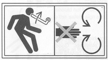
11 Hazard pictorials Danger How to avoid it Nr. Symbol Subject to danger due to insufficient information Read the manual before starting the combine 1 A raised part may fall down Support raised parts before going under them 2 Gap in belt drive Stop the engine and remove the ignition key before removing any guards 3 Getting entangled in moving parts Stop the engine and remove the ignition key before removing any guards and/or reaching into a danger zone 4 Getting entangled in rotating auge Stop the engine and remove the ignition key before removing any guards 5 Getting entangled in rotating auger Do not reach into an opening with the engine running 6 Falling into moving machinery Stop the engine and remove the ignition key before removing any guards 7 Danger caused by flying objects Keep at a safe distance from the combine 8 Kickback or upward motion of arm handle Stop the engine and remove the ignition key before inserting the handle

12 Type Marking When ordering parts or service, quote the type marking and serial number shown on the machine plate of the combine. There is a separate machine plate in cutting table. Quote also table serial number and type marking when ordering parts for cutting table. When ordering engine parts, also quote the engine number. Machine plate of the cutting table Machine plate of the combine Engine serial number Note! Left side of the combine = The side of cabin ladders Right side of the combine = The side of fuel tank
13 Supplement for 8-XP manual This combine has been equipped with Kill Switch which stops the engine after few seconds when the driver has risen from the seat. This circuit has following components: 1. Switch, assembled to driver s seat, S1 2. Time relay, assembled inside the instrument panel, K1 3. Wiring Time relay 2 has been assembled in line between ignition switch and engine injection pump solenoid. Steering current for the relay is broken with the switch 1 assembled to driver s seat. The injection pump solenoid of the engine gets current when ignition switch is on and the driver is sitting. In case the driver rises from his seat for a short time or the seat jumps up because of rough field, the engine runs normally. Time relay keeps current on for 3 4 seconds. This time is long enough to allow all normal driving operations but is short enough to prevent driver to carry out dangerous cleaning or maintaining operations while engine is running. For service reason it may be necessary to keep engine running without driver. In this case put suitable weight about 20 kg to the seat. Make sure that nobody can reach into dangerous areas! Although the time relay is adjustable never adjust it longer delay than 4 second. Check daily before beginning the work that the system operates perfectly
14 Technical specification ISO 6689 standard has been used in measuring. Length with header 6.40 m without header 4,10 m Width 2.50 m Height, - with cab 3.30 m - without cab 3.30 m Ground Clearance 0.36 m Weight*) - with cabin and 2.0 m table kg Front Tyres - wheel track 1.40/1.57 m - size / air pressure 12.4R24 1,1 Bar 360/70R24 1,1 Bar Rear Tyres - wheel track 1.27 m - size / air pressure ,0 Bar Wheel Base 1.90 m Turning Radius 3.50 m Driving Speed I km/h II km/h III km/h Engine: VM Motori D754TE3 Working Width 1.6 / 2.1 / 2.4 m Cutting Width 1.5 / 2.0 / 2.3 m Cutting Height cm Knife, Number of Strokes 460 cycles/min Cylinder - width 0.78 m - diameter 0.50 m - number of rasp bars 7 - number of revolutions r/min - optionally r/min Concave - angle of wrap length 49 cm - area 0.38 m2 - number of rasp bars 12 Separating Areas - straw walkers 1.40 m2 - chaffer 0.70 m2 Return circuit optionally - sieve 0.47 m2 Grain Tank - volume 800 / 1700 litres - unloading height 2.80 / 3.10 m Fuel Tank Volume 140 l Cooling System Volume 14 l Engine Oil 6,8 l Gear Box Oil 3,5 l Hydraulic Oil 25 l Noise level in cabin 82 db(a) (O.E.C.D-1967/6) without cab 88 db(a) The weighted acceleration subjected to operator s arms does not exceed 2,5 m/s2. (ISO-5349) The weighted acceleration subjected to operator s body does not exceed 0,5 m/s2. (ISO-2361) *) Combine in threshing condition, fuel tank filled, with driver (75 kg)
15 Opening the guards To ensure safety, the movable guards of the combine have been equipped with a locking device. They cannot be opened without an appropriate tool. The tool is delivered with every combine. It hangs on a hook on the cabin back wall. The guards are locked automatically when closing. In some guards also an additional fixing device is used. - Unlock the guard on the left side of the cutting table by placing the tool in the hole and turning in direction of the arrow. - Unlock the reel belt drive guard by pushing the latch open with the tool. Before that the rubber fittings have to be opened. The guard can be supported in an open position by means of a support rod. The rod end is placed in the hole of the lower stop bar. - Unlock the side guards of the combine by placing the tool in the hole turning in direction of the arrow. The guard is opened by pulling the lower edge outwards. The guard will be locked to open position automatically. When closing the guard release the stop by lifting the guard slightly and pushing up the stop piece located around the gas spring
16 STRUCTURE AND FUNCTION OF THE PLOT COMBINE This combine have been made for harvesting the seeds of different type of crops specially in experimental plots or smaller fields. The combine can be equipped with several special equipment for to meet customers needs. The cutting and feeding equipment take the crop in for threshing The straw dividers limit the crop to be cut and bring it within the reach of the reel. The reel, together with the crop lifters lift up the laid crop and take it from the cutting knife to the table auger. The table auger gathers the cut crop and feeds it to the crop elevator, which takes the crop forwards to be threshed. The reel is equipped with brush which cleans the front of the table after harvested plot. The air blast from the cleaning fan blows the bottom of the table and upper part of feed conveyor clean. The threshing mechanism separates the grains from the straw The threshing cylinder beats the grain off on the concave. The grain, most chaff and bits of straw go through the concave. The rear beater and the concave extension take the threshed straw material to the straw walkers. The separating and cleaning equipment screens the grains The straw walkers separate the grains from the straw and eject the straw out to the field from the rear of the combine. The grains run along the bottom grooves to the grain pan. The grain pan takes the threshed material to the shaker shoe. The chaff and light stuff are sorted topmost and the grain at the lowest during the transportation. The grain falls through the sieves at the first end of the shaker shoe to the grain conveyor and are transported from there to the top of grain tank. The grains harvested in each plot can be weighed in weighing hopper or it can go direct to the grain tank. The air stream from the fan transports the lighter trash over the shaker shoe end out of the machine. After the straw walkers, the straw is either discharged uncut into the field or taken to the chopper, which cuts and spreads it out. Special options. The combine can be equipped with weighing unit with which it is possible to measure the yield of each plots or bagging unit which allows to take grains into bags or direct to the tank. The combine can be equipped with a special corn header and other parts needed for corn harvesting. For to harvest very brittle crops there is available lower cylinder speed range RPM
17 Cutaway picture of the combine 1. Straw Dividers 2. Reel 3. Cutter Bar 4. Table Auger 5. Crop Elevator 6. Threshing Cylinder 7. Rear Beater 8. Engine 9. Gear Box 10. Concave 11. Grain Pan 12. Fan 13. Grain Conveyor 14. Shaker Shoe 15. Sieve 16. Chopper 17. Weighing 18. Grain tank 19. Straw walkers 20. Straw Alarm
 A Table Height Indicator B Flasher Indicator Switch C Steering Wheel D Brake Pedals E Parking Brake Lever F Table Clutch Control G Instrument Panel H Gear Lever J Traction Speed Control K Grain")
 A Cylinder and Fan Speed Indicator B Control Lights C Table Pressure Indicator D Warning Lights E Warning Light F Air Filter Blockage Indicator G Speedometer and Hour Meter H Thermometer I Fuel")
18 Operators controls and instruments Operator s Platform (Fig. 2) A Table Height Indicator B Flasher Indicator Switch C Steering Wheel D Brake Pedals E Parking Brake Lever F Table Clutch Control G Instrument Panel H Gear Lever J Traction Speed Control K Grain Tank Unloading L Concave Adjustment Wheel M Threshing Clutch Control N Seat Instrument Panel (Fig. 3) A Cylinder and Fan Speed Indicator B Control Lights C Table Pressure Indicator D Warning Lights E Warning Light F Air Filter Blockage Indicator G Speedometer and Hour Meter H Thermometer I Fuel Gauge K Throttle Lever L Fuse Boxes M Ignition Switch, Starter and Electric Stop N Concave Clearance Indicator O Ashtray P Electric Outlet 3 Switches (Fig. 4) A Rotating Flasher (optional) B Emergency Flasher C 4WD Switch (optional) D Cylinder Speed E Fan Speed F Front Working Lights G Rear Working Lights I Head Lights J Cutting Table Height K Reel Height L Change of Speed Indicator Display cyl./ fan M Reel Speed Control N Reel Fore and Aft Control R Horn / Reset of Tank Full Alarm S Vertical Knife Left (optional) T Vertical Knife Right (optional) U Reversing of Cutting Table


19 Signs and Symbols Ignition Lock / Starting Speed Control Lever Stop Control Engage of Cutting Table Oil Pressure Warning Light Grain Tank Unloading Alternator Warning Light Throttle Control Cylinder Speed Concave Clearance Gear Change Decal Horn Button Reel Fore & Aft Control Reel Speed Control Flashers Anti-dazzle Switch Headlights Cleaning Fan Speed Control Cleaning Air Direction Reversing of Cutting Table Working Lights Rotating Flasher Windscreen Wipers Emergency Flasher Cabin Heating Control Return Alarm Air Conditioning Control Straw Alarm Parking Brake Coolant Temperature Alarm Table Height Control Four-Wheel Drive Reel Height Control Engage of Threshing unit Full Grain Tank Grain Elevator Alarm

20 Operation and adjustment Steering Wheel (Fig. 5) To release the steering column locking, depress pedal A and move the steering wheel to the required position. Seat (Fig. 6b) 1. To adjust the fore and aft position, releaselever A and move the seat to the required position. 2. Adjust the height with hand wheel B. 3. Tilt the back rest with hand lever C 4. Tilt the arm rest with roller D. 5. Adjust the height of the seat top position with hand wheel E. 6b
21 Brakes (Fig. 7) While Driving and Turning The mechanical outer shoe brakes operate on the front wheels through the drive shafts. They may be used separately as steering brakes by releasing locking pin A. When driving on the road, the brake pedals must be latched together. 7 Brake (Fig. 7a) (models with no hand brake) By latching the brake pedals together and locking them in their bottom position using lever B, the parking brake is on. The parking brake is only used when parking the combine, and it must be released when moving. Hand brake (Fig. 8) (models equipped with it) The hand brake affects the intermediate shaft in the gear box. Use the brake only when parking, and fully release it before starting. A flashing light on the instrument panel and a steady symbol light warn of an unreleased parking brake. Those lights are on only when ignition is switched on
22 Hydrostatic Traction (Fig. 9) Engine power is transmitted to the hydraulic pump by means of a multi-groove belt. Transmission from the pump to the hydraulic motor of the gear box takes place by means of liquid. Pump output is adjusted steplessly using a drive lever between position 0 and the +/- maximum. There are three gear speed ranges, which are selected using lever A, fig. 9. Ranges 1 and 2 are for threshing and range 3 for driving on the road. Never use range 3 on the field. Gears should be changed on level ground with drive lever B, fig. 9 in neutral. The speed and direction of the combine are controlled using lever B, fig. 9. With the lever in neutral, the combine is stationary if the gear is on and the engine running. The combine will move forward when the drive lever is pushed forward from its neutral position. The further the lever is pushed, the higher the speed. To reverse the combine, pull the lever backward from the neutral position. A combine equipped with hydrostatic transmission must never be parked using only the gear, but the parking brake must always be engaged. A hydraulic engine cannot keep the combine stationary for a long period. Optional Four-Wheel Drive Four-wheel drive is switched on electrically using switch C on the instrument panel, fig. 9. The coupling can be done with the combine moving. Four-wheel drive may be used in speed ranges 1 and 2 only. When towing the combine, the four-wheel drive switch must be off and the engine running to allow the wheel motors to be disengaged. Short-distance towing at a low speed is permitted if the engine and the driving pump cannot be kept running. Switch four-wheel drive off when driving down a steep hill. The combine may rush forward unless the rear wheels grip the ground. Starting the Engine (Fig. 10)with ignition key Have throttle A in position 1, the engine idling, and the gear lever in neutral. Push the traction speed control lever to the right in the middle position. Turn the ignition key to the right. The ignition is switched on and the alternator and oil pressure warning lights come on. When turning the ignition key farther to the right, to the position HS, the engine starts. Should the aforementioned warning lights not go out after starting, stop the engine immediately and find the cause for the warning. In cold weather wait some seconds with ignition key in position 1 before starting. This is for automatic preheating of the engine. With the throttle in position 2, the engine runs at full speed

23 Stopping the Engine For stopping the engine, move the throttle into the idling position and turn the ignition key into Stop position. Do not have the ignition on for a longer period unless the engine is running. The running solenoid in the injection pump may overheat. The ignition key may be turned left from the STOP position by simultaneously pressing the key downwards. This will connect the current to the radio only. Master Switch (Fig. 11) Master Switch controls electricity for the whole combine. There is a master switch for the electrical equipment of the combine. It is located on the left-hand side of the machine, below the hydrostatic pump. The current is connected in position 1. In position 2 the current is switched off and the key can be removed. K12 CAB (fig. K12) Fresh-air Fan Provides Good Ventilation The 4-speed fan is started using switch A. To change the airflow direction, turn nozzles 1 at the front top of the cab. Air coming into the fan is taken through detachable coarse mesh and fine filters. To keep up the fan capacity and to secure the purity of the air, the filters have to be cleaned daily and replaced often enough to prevent harmful impurities and fungi from clogging the filters. In dusty conditions it is necessary to clean the coarse mesh filter several times a day. By opening nozzles 2, cab indoor air can be circulated through the fan, which reduces the need for outdoor air and thus reduces the risk of blocked filters. The windscreen wiper is controlled by switch B. Cover D can be removed and a radio set installed in the space. HEATER Provides Additional Heat from the Engine The air in the cab is heated by a heating element in which the engine coolant circulates. Turn switch E to the right to increase the amount of coolant circulating in the element. This will increase the temperature in the cab. Open nozzles 2, fig. K12, to re-circulate the heated cab air. This will further increase the temperature in the cab. AIR CONDITIONER Cools the Air in the Cab The cab can be equipped with an air conditioner system. Turn switch C to the right to switch on and regulate the cooler. Open nozzles 2 to re-circulate the cooled cab air, which will further cool down the cab. Note! A difference of over 8 o C between indoor and outdoor temperatures is harmful to your health. Keep the cab door closed when the air-conditioning is on

24 Stairs (fig 12c) The stairs to the cab can be lifted up in which position they will not damage the neighbouring plot. They are lifted (and lowered) with handle A in cab with door closed. Moving the stairs is light due to a gas spring. In case the stairs are not lifted up while driving the combine, they shall be locked in their bottom position with locking latch B. Towing (Figs. 13 and 14) Towing the SR 2010 is allowed from designated points only. The combine may be towed from the points marked for that purpose. When towing forward, fasten a link round the front axle, Fig. 13. To tow backward the towline round the rear carrier, fig. 14. Do not fasten the wire round the rear axle. While the combine is being towed the driver shall be in the cab and the engine running to keep power steering working. The brake pedals shall be latched together and gear on neutral position. Four-wheel drive shall be switched off. In case it is impossible to start the engine the towing have to be done very carefully because in this case steering is slow and heavy. When towing on the road statutory traffic regulation shall be followed

25 Threshing equipment Warning Lights (Fig. 15) The alarm system of the combine indicates if: A. Blockage in the grain elevator B. Blockage in the bottom auger D. Blockage in the chaff hood F. Blockage in the air filter G. Grain tank full H. Unloading pipe unlocked I. Engine overheated J. Hand brake engaged In case of alarm, light E on top of the instrument panel blinks and the light on signal panel K or L indicates the place concerned. The grain tank full alarm can be switched off by sounding the horn. 15 Straw Dividers (Fig. 16) Straw dividers have to be adjusted. The straw dividers are fitted on both sides of the cutting table. Their height is adjusted by means of holey slide pieces D. Adjust guide plates A to suit the threshing conditions. The side guide tube is attached to the divider at the front and to the table side at the rear. Alternatively also bow-type of straw dividers are available. Those can be used especially when harvesting short straw crops. Those dividers operates well also when harvesting crops which are very difficult to divide like turnip rape or flax. Space Crop Lifters correctly (Fig. 17) The appropriate number of crop lifters for a 1.5 m table is four, for a 2.0 m table six. Attach the crop lifters with the fixing screws of the knife fingers as shown in the picture. The lifters can be assembled to the place where bolt hole is through the upper plate of table. The crop lifters operate best when the minimum cutting height is 8 to 10 cm. It also helps to avoid the stone to be picked up

26 Reel settings (Figs. 18 and 19) Reel has four adjustable settings Reel height is controlled by switch A, Fig. 18. Reel speed is controlled by switch B. Speed should only be changed when the reel is rotating. Fore and aft adjusting is controlled by switch C. Adjusting of reel angles is done when screw D is slackened, Fig. 19. Especially when harvesting laid crops, it is good to adjust the tines to gather the crop efficiently. The reel is fitted with safety clutch E. It is advisable to check the function of the safety clutch at the beginning of each harvest season. See instructions under Maintenance. Engage the safety stop F, Fig 19, before reaching below lifted reel Cutting Knife in good condition! There are no actual points to be adjusted in the knife during the threshing procedure. In any case, see to it that the knife is in a perfect condition since good threshing result begins with the cutting capacity of the knife. For more precise service and adjusting instructions, see under Maintenance. The spare knife is stored in a box on top of the cutting table
27 Table Auger (Fig. 20) height and finger positions are adjustable Adjust the table auger vertically to suit the lot of straw in the crop being threshed. E.g. in strong rye and turnip rape adjust the clearance between auger and cutting table wider, approx. 30 to 40 mm. To adjust, loosen screws A on both ends of cutting table and the table auger can be lifted or lowered as required. Clearance between table auger and bottom has to be the same on both ends of the table. The normal clearance is 15 mm. After moving table auger, check feed finger adjustment and drive belt tension. Feed finger position is adjusted, when screw E has been loosened, with lever B on the right and end of the cutting table. Minimum acceptable clearance between the bottom and finger tips is 10mm. Crop Elevator Chain (Fig. 21) correct height and tension The elevator has a fixed top roller and a floating bottom roller to enable the elevator to smooth out the flow of crop to the cylinder and to handle a fluctuating feed. Adjust the clearance between the bottom roller and the bottom of the elevator housing by the screws C. Correctly adjusted, there should be a clearance of 0 to 5 mm between the lowest slats and the housing. The elevator chain is adjusted with screws D. Check the tension through the inspection door in the top of the elevator housing. The tension is correct when the deflection midway between the top and bottom rollers is approx. 50 mm. The bottom of the crop elevator can be adjusted depending of the crop harvested. For cereal and small seed it is kept in upper position for good cleaning. For corn it can be lowered to avoid grain damaging

28 Table Auger and Crop Elevator Reverse Drive (Fig. 22) eliminates blockage on the table Blockage in crop feed might stop the table auger and crop elevator. This can be cleared by running them backwards. To do this, disengage the drive to the table with the pedal and press the reverse switch A. The table auger and elevator will rotate in reverse direction, clearing the blockage. NOTE! The reversing will only operate when the table drive have been disengaged and the engine is running. 22 Cutting Table (Figs. 23 to 26) Throw-out clutch and supporting The throw-out clutch for the threshing and feeding mechanism is controlled by a foot pedal on the right-hand side of the operator s platform. Press the front of the pedal to disengage the drive mechanism and press the rear of the pedal to re-engage the mechanism. CAUTION: The cutting mechanism disengaged by the pedal can start running when, for instance, feeding disorders are eliminated from the table. Therefore, always stop the engine before any work is carried out on the table. Before repairing and maintenance beneath the table, raise it to its full height and lock the support over the ram by means of the lever B, Fig. 23, on the left-hand side of the feed conveyor. Do not use the cutting table support during transportation
29 The table height is controlled by switch A, Fig.24. Cutting height is shown on the scale, fig. 25. The cutting table is eased using a gas accumulator, and the easing pressure is shown on gauge A, fig. 26. With the needle in the green field of the gauge, the table fully rests on the gas accumulator. When lowering the table onto the ground, the easing effect of the gas accumulator decreases and the needle goes to the red field. The farther red the needle goes, the more heavily the table lies against the ground, in which case soil or stones get easily onto the table and damage it. When threshing laid-down crops, adjust the table height so that the needle is in the green field or on the border between the green and red where the easing effect of the gas accumulator is still sufficient. When necessary, the colour scale on the table pressure gauge can be adjusted by turning the glass. The needle shall be in the green field, approx. 5 mm from the red field when the cutting table is off the ground at the height of approx cm
30 Engage Threshing Mechanism at engine idling speed only (Fig. 28) Engage the threshing mechanism with lever A. Then the threshing cylinder, straw walkers, grain pan, shaker shoe, grain elevator and straw cutter are started. NOTE! Engage and disengage the threshing mechanism at engine idling speed only. Threshing Cylinder (Fig. 29) Stepless control of cylinder speed The speed of the threshing cylinder can be changed steplessly with switch C. The speed can only be changed with the threshing mechanism running. Cylinder speed is displayed in gauge A on the instrument panel with change switch B in the cylinder position. Recommended settings for the most common crops are displayed on the cab window. Concave (Fig. 30 and 31) Adjusting of the clearance The clearance between the threshing cylinder and concave is steplessly adjusted by means of regulating wheel A on the right hand side of the operator s platform. Turn the wheel anticlockwise for wider clearance and clockwise for smaller clearance. The needle on the scale B gives the clearance C, that is the distance in mm between the first concave beater and cylinder beater. Fig The control mechanism has been designed to keep the ratio between the front and rear clearances constant. The normal ratio is 2:1; the front clearance C is double the rear clearance D, Fig. 31. The concave clearance should be checked at least once at the beginning of each harvesting season. See the settings for adjusting for various crops in the table
31 Concave filler plates remove awns (Fig 32 and 33) The threshing ef fect of concave can be improved by fitting the filler plates A under first concave beaters, Fig 32. Pass the filler plates through the holes in both ends of the concave. The spring keep them fixed. A maximum four plates can be fitted. For assembling filler plates, remove canvas A, (Fig 33) from front end of grain pan. Reassemble canvas after assembling plates. Note! When using filler plates, some grains may remain on the concave after finishing each plots. Do not use filler plates if this kind of mixing of grains is not acceptable. Reversing of the Cylinder In case of blockage in cylinder it can be reversed by a reversing tool delivered with the combine. Fig 33a. The engine shall be stopped and the clutch of threshing unit disengaged. Adjusting the concave to lowest position will help reversing. Possibly the plockage have to be removed also through access doors

32 Straw Walkers (Fig 34) Clean the bottoms. Check the bottom grooves of the three-part straw walkers daily and clean if necessary, especially when working in difficult threshing conditions. With large straw quantities, the extensions of the bottom grooves can be pulled out, to cut down the walker losses. With small quantities of straw, particularly in barley, a lower cleaning capacity is needed, the bottom grooves can be achieved by pushing in the extensions. An alarm on top of the chaff hood gives a sound signal if an excessive accumulation of straw causes a blockage such as on overload of the straw cutter. Then, immediately disengage the threshing mechanism, clear the blockage and find out the cause of the trouble before going on working. NOTE! Always check the operation of the warning device daily, before starting the work in the field. Shaker Shoe Grain Pan (Fig. 35) The shaker shoe and the grain pan have been built compact. There is one adjustable sieve. The opening of sieve lamelles are adjusted by the screw D in the rear of the sieve. To remove sieve slacken the screws A, whereby the locking pegs B move towards the centre and disengaged from the lugs C. The sieve can be pulled out on the slide bars. Shaker Shoe with Return System (Fig 36) The shaker shoe with return system has two sieves. The top sieve is adjustable like a standard one. The bottom sieve is changeable round hole sieve. The sieves with different size of holes are available for different crops. The place for bottom sieve (A) have been built to the top sieve. For to change the bottom sieve also top sieve are removed. The bottom sieve can be removed by loosening bolts B, Fig 36. For special conditions the returning system can be blanked by assembling blanking plates C, Fig 36, to the end of grain bottom of shaker shoe. This guides all grains direct to grain elevator and shortens emptying time of the cleaning unit
 NOTE! Adjustments can only be made with the threshing machinery engaged.")
33 Cleaning Fan (Fig. 37) for providing sufficient air flow The air flow is adjusted by changing the speed the fan by variator. The speed regulating switch has been located on the instrument panel. Fan speed is displayed in gauge A on the instrument panel with change switch L in the fan position. (Fig. 3 and 4.) NOTE! Adjustments can only be made with the threshing machinery engaged. For small seeds requiring less air flow than provided by speed of the fan, open the door A beneath the fan, fig 37. Adjust the air flow direction by regulating lever D Fig 37. When the lever is in its extreme position down, the air is directed forwards and up. By moving the lever upwards, the air direction turns down and backwards. The suggested settings for the air flows and directions for various crops are given in the table. Grain Conveyor Chain (Fig. 39) Grain conveyor chain transports grains to the to the bottom troughs and is then taken to the weighing unit or direct to the grain tank by means of the conveyor chain. When no more grain falls from the shaker shoe, the conveyor chain cleans the bottom trough automatically. An alarm will indicate a drop in the elevator speed because of overload or loose belt. After having cleared a blockage, operate the threshing machinery at low speed for some time before continuing threshing
34 Return auger (Fig 40) Optionally the combine can be equipped with return system. The return auger consists a bottom auger and a blower fan which throws returns back to grain pan. For ease of cleaning, the bottom of auger can be opened. To increase the threshing effect of the fan the smooth bottom part can be replaced with a corrugated one. This will be done by slackening screws A. Weighing Unit (Fig 41a) Weighing unit, if fitted, is located at the top of the grain tank. The grains come from grain conveyor to the weighing hopper, when assembled. Grains drop from the weighing hopper direct to the grain tank. With an optional sample taking devise below the weighing hopper it is possible to take a sample while unloading theweighing hopper. There may be different type of weighing systems depending of final spesification. When harvesting larger fields the grain can be taken straight to tank by keeping the bottom door opened. Bagging unit (Fig 41b) if fitted When the bagging unit have been fitted, the grains can be taken into tank or into bag by turning the guide A, fig 41b. There are places for two bags. The bag which is filled is chosen by turning a guide B. The height of bag holder C is adjusted by changing the bolt D from one hole to another. The Bag holder D can be swung to the left for to open the side guard of the combine for service reason
35 Grain Tank (Fig. 42) The grain tank is filled by the grain conveyor with or without the weighing hopper. An alarm sounds when it is full. The height of the alarm sensor can be adjusted by moving the sensor from one hole to another. This will either advance or postpone the alarm. The grain tank full alarm can be switched off by sounding the horn. The alarm will be activated again when unloading the tank. If it is unavoidable, because of cleaning or maintenance, to work in the grain tank. Stop the engine and remove the ignition key that no unauthorised person is able to start the engine. The bottom auger can be removed for easier cleaning by loosening thumb pin B. Unloading Auger (Figs. 42, 43 and 44) Swinging and function The grain tank is emptied with the unloading auger, with the threshing mechanism engaged. To engage the unloading mechanism pull up lever A (Fig. 43) and to disengage it press the lever down. To bring the unloader auger into the unloading position, lift locking clasp A ( Fig. 44) up and push the pipe into forward position, where it is automatically locked. To return the pipe to the transport position, push lever D (Fig. 42). The pipe is unlocked from the unloading position and automatically locked in the transport position. NOTE! As the unloading pipe is operated with a spring, make sure before releasing the locking that the pipe can move freely
36 Straw Chopper Danger zone (Figs. 45 and 46 ) Always stand well clear of the straw chopper while in operation. Never make adjustments or clean the chopper while the engine is running. Never stand in the danger zone behind the chopper either, when it is rotating. The degree of cutting can be varied by turning the counter knife beam A, Fig. 45. To do this, slacken screws B and C on both sides of the cutter and by means of the lever in the left-hand end of the beam turn it as required. With the counter knives at right angles to the rotor centre, the straw is cut short and cutting absorbs more power. With the counter knives down from the rotor centre, the chaff gets longer and the power demand smaller. In their lowest position, the cutting action is small, but however sufficient and recommended for turnip rape. The distribution pattern is varied by changing the position of the spread hood D after slackening screws E in the holes on both sides of the chopper. In the upper position the chaff is distributed over a wider area, while it is smaller with the spread hood in its lower position. The finer adjustment can be achieved by changing the position of the vanes F. NOTE! Avoid adjusting the spread hood positions so that the chaff spreads into the crop not yet cut as that can block the knife, overload the sieves and result in a poor grain sample in the tank. The chopper can be moved into the out of work position, Fig. 46, as follows: Remove bolts E, fig 46, and turn the spread hood D against the straw hood Remove the drive belt from the pulleys and take it away from the machine. Release the locking screws F both side of the chopper Pull the cutter backwards to the end of the slide bars and lock it by the screws F The chopper is put to operation opposite way. Check proper belt tension after assembling. NOTE! For safety reasons, always take the belt of when the spread hood has been turned against the straw hood
37 Engine, Source of Power See detailed information of engine from separate Engine Owners Manual The engine is a water-cooled four stroke direct injection turbocharger diesel. The drive is transmitted from the engine flywheel through the flexible coupling and poly V-belt to the hydrostatic pump and from there to the threshing machine. Suction Air Filters The engine suction air is cleaned by two-part paper filter. The filter is located in the engine housing behind the engine. On the instrument panel there is a blockage indicator, the glass of which will turn red, if the vacuum in the engine suction channel becomes too high. See cleaning instructions under Maintenance. Fuel Tank should be filled with pure fuel only The volume of the fuel tank is 140 litres. The fuel level is seen in the gauge pipe in the end of the fuel tank. Use Diesel Oil as fuel. It must be pure and waterfree. Before refuelling, remove all impurities around the filler plug A. Never empty the storage tank completely as impurities and water tend to settle on the bottom. Daily checkings Lubricating system It is essential to use correct lubricating oils, which correspond to the characteristics of the engine. See the separate engine instruction book Check the oil level daily before starting. It should never be allowed to drop below the minimum mark nor exceed the maximum mark of the dipstick. A warning light on the instrument panel indicates low oil pressure. Should the oil pressure warning light glow when the engine is running, stop the engine immediately and find the cause of the trouble. Cooling System Liquid and Cleaning When the combine leaves the factory, the engine cooling system has antifreeze added. Do not use ordinary water as coolant because of the risk of corrosion. Check the radiator coolant level daily before starting. The level of coolant shall be about 20mm below lower edge of the filler neck when being cool. The coolant thermometer on the instrument panel indicates the temperature of the engine coolant and in normal working conditions it must be between 75 and 95 degrees centigrade. A signal light on the instrument panel and a flashing warning light reveal the coolant overheating. If the temperature starts to rise, check that the outside of the radiator is not clogged. Use a high pressure hose to blow air from the side of the fan through the radiator or a brush to clean it. But always be careful not to damage the lamellas. To clean the equipment, open protective cover above the radiator. Any impurities are removed through the emptying door below
38 Driving and threshing instructions Before starting the Combine, check that: There are no foreign objects inside the combine The oil levels are correct (engine, gearbox, hydraulic tank) There is coolant in the cooling system There is fuel in the tank The threshing machinery and unloader clutches are in neutral Always before starting warn those nearby with sound signal. Starting the Engine: With the hand throttle lever on idle, and the traction speed control in the middle position pushed to the right, switch on the current on by turning the ignition key to the right. Then the alternator warning light and oil pressure warning light come on, and when turning the key farther to the right, position HS, the engine starts. Should the warning lights not go out after starting the engine, immediately stop the engine. Cold Weather Starting: To start the engine in a temperature below -0 degrees centigrade, turn the ignition key to the position 1 for some seconds for preheating and then start with the key in the position HS. If the engine has not started within some 10 seconds, turn the key to 0 and try again in same way. NOTE! Never start the engine in a temperature below -30 degrees centigrade as then the traction hydraulic oils are too viscous (In case if VG46 oil has been filled the minimum temperature is -15 centigrade.) and the equipment may be damaged. (The maximum allowed viscosity of hydraulic oil is 1500 cst when starting.) NOTE! If the temperature is below 0 degrees centigrade, let the engine idle for some 15 minutes, to allow the hydraulic oil to warm sufficiently. Stopping the Engine: Turn the ignition key to the position STOP. NOTE! Do not stop the engine immediately after threshing. Idle the engine for a few minutes to allow it cool off and the temperature to equalise. Starting off: Select the required speed range by gear lever. When the traction speed control lever is slowly pushed forward, the combine starts mowing forward. Reverse by pulling the traction speed control lever backward. Gear 3 is only for driving on the road when grain tank is empty. Never use gear 3 on the field. Driving on the Road: The brake pedals must be latched together. Lower the speed and brake smoothly as the rear wheels easily rise from the ground when applying the brakes violently. Never drive downhill with the gear in neutral. The grain tank shall be empty, the knife guard mounted, the front lights correctly adjusted and the head lights on. Never drive with full speed when turning. The combine is high machine and it may fall easily
39 Driving in the Field: The steering brakes may be used for reduce turning radius. When reversing, it is not necessary to use the steering brakes. Never use the third gear in the field Soft Field Conditions: To improve the floating capability, the air pressure of the front tyres may be reduced by 20 kpa (0.2 bar). Do not reduce the air pressure of the rear tyres. With reduced tyre pressure, only half-fill the grain tank. When returning to normal harvesting conditions, return to recommended pressures. On Steep Slopes: Increase the tyre pressure by approximately by 30 kpa (0.3 bar) to improve stability of the combine. Only half-fill the grain tank to eliminate the risk of overturning
40 Threshing instructions Choose the Correct Time and Conditions Before starting the harvest make sure that the crop to be threshed is ripe and dry enough. The germinating power of most crops is easily reduced if the threshing moisture exceeds 25%. Moreover, moist crops complicate harvesting and overload the threshing machinery. They also easily stick on the surfaces of the separating equipment and elevators, so that the combine must be cleaned more often than usually. Good Threshing Result with Even Feed Always run the engine at maximum speed. When the machine is in operation, it is important to adjust the forward speed, cutting height and the reel according to crop conditions, to achieve as even a feed as possible into the machine. Do not cut too low. Leafy matter moistens the straw leading to a poor threshing result. Start With the Recommended Settings In the table you will find settings and adjustments for different crops. After adjusting your combine according to those recommended settings, check the sample after a test run at the speed you will use in harvesting. Observe the quality of the sample coming into the tank and the losses in the field. NOTE! When threshing heavy strawed crops without chopper, it is important to observe that the straws come out of the straw walkers without clogging the chaff hood when the combine is stopped. Reel Position in Accordance With Crop For normal standing crops, set the reel in its rear position at such a height that the reel tines lightly strike the crop. Reel speed slightly higher than the combine ground speed, with the crop feeding head first, Fig. 48. For short-strawed crops, lower the reel so that the tines strike just above the knife. The higher the reel speed, the shorter straw is cut with the heads. The reel must pull in the heads toward the combine. For long-strawed standing crops, set the reel in its forward position, the speed less than the combine ground speed so that the heads are pushed forward and the crop is laid butt first to the threshing machinery, Fig. 49. For laid crops, set the reel forward, reel speed higher than the combine ground speed and the reel angled to facilitate the gathering of the crop, the knife cutting below the heads, Fig. 50. When using crop lifters, the reel should feed the cut crop on to the table auger with the reel tines in the normal position
41 Adjust the Straw Dividers To Reduce Table Losses and To Improve Feeding To avoid threshing losses caused by straw dividers, pay special attention to adjusting them according to the conditions and crops. Adjust the height of the dividers with the slide piece so that in laid crops the dividers follow the contours of the field beneath the crop. In standing crops the head of the divider should be set 10 to 15 cm above the knife. Long-strawed reclining or laid crops are lifted by the upper guide plate so that the reel can gather the crop for cutting and conveying onwards to the table auger. The outside guide tube is used in crops with long straw to move the uncut crop a side. Estimation of Threshing Losses 2 per cent is generally considered to be the upper limit of threshing losses. It can be proved as follows: With an estimated yield of 3500 kg/ ha, the weight of 1000 grains is 35 g; when observing the width of the combine, max. 2 grains may be found on the area of 1 sq. dm (a hands-breadth). Sources of grain loss: Shedding in the field before harvesting From the table Unthreshed grain From the shaker shoe From the straw walkers Before readjusting, make a methodical check in the above order to isolate the cause of the loss. Make one adjustment at a time and check the result with a test run. In the Field Before Harvesting, check the crop well in front of the machine to ensure that shedding has not occurred before the machine has touched it. To test for the table loss, stop the machine and reverse it one combine length; the grain loss can easily be seen in the field. Causes of table loss: reel position or speed incorrect local blockage in knife resulting in a pressed or uncut strip in the stubble; cause: a damaged knife or finger
42 Unthreshed Grain Check that the grain is being threshed from heads. With a chopper fitted, examine the heads on the straw before chopping. Cylinder speed should be moderate and concave clearance as wide as possible, to have unbroken grain and straw as well as small loss from the straw walkers. It is not necessary to achieve complete threshing. Unthreshed grain loss can be caused by: cylinder speed too low cylinder-concave clearance too wide uneven feed crop too green in parts damaged cylinder or concave. Shaker Shoe Losses If the sample coming from the sieves (taken on a shovel, for example) shows grain being lost, check for the following: excessive or insufficient fan speed direction of cleaning fan air flow incorrect blocked sieves chauffer sieve not sufficiently open crop too damp too much weed Straw Walker Losses If the sample coming from the straw walkers shows grain being lost, check the following: uneven feed blocked concave and/or straw walkers excessive forward speed cylinder-concave clearance too small too much weed crop too damp Quality of Sample in Tank If there is crushed or cracked grain in the sample, the reason could be: cylinder speed too high cylinder-concave clearance too small blocked concave crop too green in parts If the sample is dirty, the reason could be: insufficient fan speed cleaning fan deflectors incorrectly set chauffer sieve set too far open forward speed too low (inadequate loading of the threshing machinery) crop sparse in places and weedy excessive cylinder speed, cylinder concave clearance too small too much time spent out of the crop (turning etc.)
43 Function Problems If the cylinder winds up and gets clogged, check for: crop too damp or green forward speed too high cylinder-concave clearance too wide cylinder speed too low cylinder bars damaged or worn rear beater damaged If the grain conveyor is clogging, check for: chauffer sieve set too far open insufficient fan speed Cleaning Instructions When Going From One Crop To Another Although the combine has been built to self-cleaning it is necessary to clean it carefully when going to one crop to another. Some grains may be left anyhow. This may happen especially when harvesting in wet condition. Drive the combine to suitable open place. Move gear lever to neutral and engage the parking brake. Stop the engine and remove the ignition key so that no unauthorised person can start it. Do not carry out any cleaning operation while engine running Cleaning with compressed air is recommended, also appropriate brush can be used. Open all cleaning doors. Remove sieve and clean it. Clean the supporting grooves of the sieves in the shaker shoe. Clean the straw walker bottoms Run the combine threshing machinery for 2 to 3 minutes with the cleaning fan at maximum speed and pushing the direction lever to and fro. Lift and lower the cutting table against the ground without starting it. Stop the threshing machinery. Check that the grain pan is empty; if necessary clean it. Check the spaces below the grain conveyor and remove any grain remaining. Shake the chain of the feed conveyor and clean the housing inside and out. Clean up the cutting table. Remove the bottom auger of the grain tank and brush up the bottom furrows. Clean the unloading pipe by agitating and turning the auger by hand to the left while the pipe is unlocked and the grain is running down off the lower pipe end. Fit the parts removed properly and close the doors
44 Average settings for threshing This table only gives average settings. While threshing, adjust the settings according to the harvesting conditions. Crop Cylinder speed RPM Concave clearance (mm) Top sieve opening (mm) Bottom sieve 1 Fan speed (rpm) Air Blast direction Notch Rye Wheat Barley Oats Turnip Rape Timothy *) 3 Meadow fescue *) 2 3 Clover ***) *) Alpha alpha ***) *) Pea **) Soybean **) Maize **) Sun Flower **) ¹ (if return system fitted) *) With open bottom of fan housing **) Use wide space, heavy wire concave ***) Use 3 4 deawning plates in front of concave The normal concave front to rear clearance ratio is 2 to 1. In dry conditions when the straw is extremely brittle, it is better to use a concave ratio of 1.5 to to 1, see fig. 31. In other words, the clearance at the rear of the concave is bigger than in the normal setting. This will reduce straw damage and therefore walker losses. The basic setting is changed by extending the rear supports of the concave as instructed in chapter Maintenance fig. 66. The ratio shall be checked every time the clearance is adjusted using the wheel in the cab. The mechanism always changes the clearance in the ratio of 2 to 1. Return to the basic setting as soon as the conditions get back to normal
45 Service and maintenance SAFETY Safety regulations and instructions Installations and adjustments can only be made by a person with the required skills and qualifications and the necessary knowledge of the machine in question. Installations, adjustments and repairs must be undertaken with the engine stopped and the ignition key off. All the moving parts must be in balance and stopped and, when necessary, locked. Support the cutting table and the reel in their top positions. Ensure that there is no pressurized energy in the fluid systems before opening mechanical or hydraulic couplings. (The gas accumulator for the table, the air conditioning equipment, the radiator, etc.) Double-check that there is no risk of injury when starting the engine either during or after service measures. Ensure that all periodic checks and cleaning are carried out on time in compliance with the instructions so that no such malfunctions may occur which can cause any risk or hazard. When installing, adjusting, servicing or repairing a technical device, without unhampered visibility to all its parts, or on which several people are working, or which is started from a control centre, or which is started from such a place that the whole device can not be seen, it must be ascertained that the device may not be started unintentionally or defectively. This can be guaranteed by locking the starting device in the stop position. When installing, adjusting, servicing or repairing a technical device with energy reserves, no measures are allowed to be taken before it has been ascertained that no hazardous machine movements may occur. When starting a technical device, the operator must ascertain that nobody will be injured. The service and periodic checks of a technical device must be carried out in accordance with the Manufacturer s instructions and operating conditions so that no such malfunctions may occur which can cause any risk or hazard. General Instructions Make sure you are skilled enough to service the combine before undertaking any maintenance work. If not sure, contact a qualified service man. Get acquainted with the combine structure and the following service instructions before undertaking any work. Wear appropriate protective clothing. Use appropriate tools and other equipment. Handle the combine and any work materials in such a manner that there s no risk of injuring yourself or anybody else, or damaging the environment
46 The Functioning of the Combine Is Based on the Condition of the Knife Check that each knife holder touches the knife section lightly. Adjust by bending the holder down, fig. 52. Check the reversing points of the knife, fig. 53. The knife sections should centre in the knife fingers at the inner and outer extremity of its stroke. If adjustments are made, make sure that the knife joint is turned into the right depth at the end of the knife, fig. 55. The final adjustment is made by removing both clasp nuts B of knife drive shaft A, fig. 54, and turning the shaft in the required direction. When turning clockwise, the reversing point is shifted to the left, when turning counter-clockwise, it is shifted to the right. One turn of the shaft shifts the reversing point by some 7.5 mm. Removing the Knife When removing the knife count the number of turns required to unscrew the ball joint. Remove fixing screws A, fig. 55, on the connecting lever and remove the knife. When changing the knife, loosen lock nut B on the ball joint and count the number of turns required to unscrew the ball joint from the knife. Screw the ball joint into the end of the new knife using the same number of turns and check if the reversing point of the knife needs adjusting

47 Check the Knife Fore/Aft and Up/Down Positions. Adjust the height by moving the drive lever in its bearings. The fore/aft direction is adjusted using screw joint A, fig. 55. The up/down position is correct when the bottom surface of the first knife section brushes the cutting surface of the knife finger. The fore/aft position is correct when the knife tang and the joint fixing piece can move freely for the whole length of the stroke without brushing the edges of the groove or the heads of the locking screws on the knife finger. Make sure the knife moves lightly when turning the table auger drive pulley by hand with the table disengaged. Replacing and Aligning of a Knife Section Remove the knife section by knocking out the rivets according to Figs. 56 and 57. Rivet up a new knife section. Use a riveting core to tighten the section to knife tang 1 and shape rivet head 2, fig. 58. Tool R
48 Align the knife sections according to Figs. 59 and 60 when replacing one. Alignment of the Knife Fingers Check the heightwise position of the knife fingers. The heightwise difference between the cutting surfaces of adjacent fingers must not exceed 1 mm. Visual inspection can be made by checking the alignment of the fingers from the side of the table. Straighten or replace bent knife fingers. It is important to remember that the two pairs of knife fingers on the left differ from the other fingers
49 Table Auger Fingers Must Be Straight Straighten or replace a bent finger. To remove the finger, which is necessary in both cases, open the door in the table auger housing and turn the auger until locking screw A can be unscrewed, fig. 61. Place reel supports before undertaking any work! A bent finger wears the guiding bearing quickly, so check the condition of the bearing when replacing a finger. Check the Overload Clutches of the Cutting Table Before Starting Threshing The function of the overload clutches protecting the knife, table auger and reel must be checked annually before starting threshing. The best way to do this is to slacken nut A, fig. 62, which tightens the cup spring pack, so that spring pack B will slacken. After this, turn belt pulley C (and the reel) to ensure that friction plate D is not stuck. Open the clutch, if necessary, and remove any rust from the friction surfaces. After checking, tighten the spring pack to its original measure E. Table width Measure E 1.5 m 12 mm 2.0 m 12 mm 2.3 m 11 mm

50 Removing of the TABLE in the Correct Order Lower the reel into its lowest position. Stop the engine. Disconnect the quick release coupling to the hydraulic piping of the reel and the electric connection on the right side of the crop elevator. Unlock the locking between the lower corner of the crop elevator and the rear of the table, fig. P1. Remove the belt guard on the left-hand side of the crop elevator and slacken the cutting table drive belt by moving jockey pulley A, fig P2. and remove the belt off the drive pulley of sliding coupling shaft. Disconnect the feed cable for the table reverse from the quick release. Disconnect the air hoses from the table on both side of the crop elevator. Place the table support in between the knife fingers in the approximate centre of the knife as shown in fig P3. Have a pallet or another appropriate platform ready onto which the table can be lowered. Lower the table ensuring that the support remains in position and that the table comes away from the crop elevator. Start the engine and let it run at idling. Drive the table on top of the platform and lower it onto the support ensuring that the support remains in position andthat the crop elevator becomes disengaged from the table. When the crop elevator is entirely off the table, reverse the combine checking that the table does not move
51 Cylinder/Concave Clearance Periodically, preferably at the beginning of each harvesting season, check the position of the concave in relation to the threshing cylinder, in other words the cylinder / concave clearance. Use tool No. R for checking, Fig 66. Follow the instructions: Set the concave adjustment lever to position 12 and check the clearance, which should be 12 mm at the front (between the first concave rasp bar and a cylinder rasp bar) and 6 mm at the rear (between the last concave rasp bar and a cylinder rasp bar). If this is not in order, adjust the clearance by nuts B at the lower end of the concave adjusting arm A, Fig. 67. The check measuring should be done in every concave edge
 between nut A and lever B (Fig 69) shall be 6...8mm. To adjust, loosen nut A and turn bushing C to required direction. Cylinder Variator Belt (Fig.")
52 BELT ADJUSTMENT NOTE: Check the tension of all belts after the first day of harvesting. Adjusting Threshing Mechanism Drive Belt (Fig. 68) Engage the threshing mechanism with the engine switched off. The clearance (X) between nut A and lever B (Fig 69) shall be 6...8mm. To adjust, loosen nut A and turn bushing C to required direction. Cylinder Variator Belt (Fig. 69) To tension the belt, tighten anchor bolts A and C (on the housing) and the connecting bolt B (between the variator arms). Then you have to screw the connecting bolt two turns per each turn of the anchor bolts, to retain the transmission ratio of the variator. When tensioning the belt, rotate the pulleys by hand so that the belt moves uniformly on the pulleys. Check the belt tension when variator is about in middle of range. The tension is correct when the measurement of the spring washer set in the lower end of arms is 23+1mm. The arms shall be adjusted so that they do not take a contact to the pulleys by minimum or maximum speed setting. At maximum speed setting the belt shall be even with the pulley edge in the ear beater shaft. At minimum speed setting the belt shall rise mm over the pulley edge in the cylinder shaft. Cutting Table Drive Belt (Fig. 70) Engage the threshing mechanism with the engine switched off. Slacken counter nut A of the coupling arms adjusting nut and turn up the upper nut B until the belt tension is correct. Lock up nut A
 The belt tension is correct when the measurement X is 6..8 mm. To adjust, slacken nut A and turn the bushing B required direction.")

53 Grain Tank Unloader Belt (Fig. 72) Slacken counter nut A on the draw bar and turn nut B to tighten. Lock up nut A. Traction Hydraulics Belt (Fig. 73) The belt tension is correct when the measurement X is 6..8 mm. To adjust, slacken nut A and turn the bushing B required direction. Fan Variator belts (Fig 74) Slacken nut A on the middle shaft of the variator pulleys and nut B. Then rotate Screw C, so that pulleys move in the direction of the arrow and belts are tightened. After adjusting, screw up nuts A and B. After adjusting tightness of belts, check that free control range of pulleys is not too long. Belt shall not rise over pulleys edge at the ends of range. Adjust stop nuts D if needed
 Slacken fixing screws E and D of the pump and crank back the pump to tighten the belt.")
54 Reel Variator Belts (Fig. 75) To tighten the belts slacken nut A at the end of the middle shaft and turn screw B so that the pulleys move upward tightening both belts tighten uniformly. After adjusting, tighten the slackened shaft. Belt of the Working Hydraulics Pump (Fig. 76) Slacken fixing screws E and D of the pump and crank back the pump to tighten the belt. The tension is correct when the deflection is approximately 15 mm when pressing the belt with a thumb midway between the shafts. Spring-loaded Jockey Pulleys Spring-loaded jockey pulleys automatically tension the belts of the straw walkers, table cleaning fan and the grain conveyor. If the belts seem slack, they can be tightened by moving the fastening of the pulley spring to the next notch. Stationary Jockey Pulleys (Fig. 77) To tighten driving belts of the shaker shoe, straw chopper and table auger, slacken the middle shaft A of the jockey pulley and either by screwing nut B or by moving the jockey pulley by means of a suitable lever, tighten the belt as required

55 COMPRESSOR BELT IN THE AIR CONDITIONER Tension is correct when the belt deflects some 5 mm (50N = 5 kg) when pressed with the thumb. To tighten the belt slacken locking nuts A and Turn regulating nut B, fig. P32. Tighten screws A
56 Tightness of V-Belts, generally (Fig. 78) Check by pressing The belt with your thumb midway between the shafts. Shaft distance Deflection a/mm f/mm less than Place the Bows and Belt Supports as They Were Before Changing Check, when changing the driving belts of the threshing machinery, unloading of grain tank and cutting table especially that the belt supports and the bows round the pulleys are re-fitted correctly. Mark the places before removing the parts to ensure re-assembly in the same positions. Tighten the new belts after a few hours of working. Always use original belts because their quality has been tested by the factory and meets the specific requirements. Tightening of the Reel Chain To tighten the reel chain lower the reel on its supporting arms. Grain conveyor Chain (Figs 79) Check the tension of the chain and, if necessary, tighten after first 30 hours of harvesting and thereafter at intervals of about 100 hours. Periodically check the condition of disc sections. To tighten the chain: Slacken the nuts B locking the shaft of the sprocket A (Fig. 79) Using appropriate lever move the sprocket outward so that the tension is correct. Lock the nuts B
on both shaft ends Turn the plate B a quarter turns.")
57 Adjusting of Worn Disc Sections (80a and 80b) If the clearance between a chain disc and the bottom trough is more than 1 mm (with correct tension of the chain) the chain must be adjusted so that it runs closer to the bottom trough. Adjust on both side of the combine. Right side: Slacken nuts A (Fig. 80a)on both shaft ends Turn the plate B a quarter turns. The centre hole in the plate B is eccentric. When the three holes of the plate are in bottom, the chain is its farest from bottom of trough. If the plate is turned a quarter turn, from three to two holes, the chain is moved 1 mm closer to trough bottom. Turning the plate gives total 3 mm adjustment. When the side of plate without holes is at the bottom, no further adjustment of the chain is possible, and the discs must be replaced if the clearance between discs and bottom is wider than 1 mm After adjusting the plates tighten the chain. Left side: Adjust the eccentric shaft of the curve connecting the bottom trough and vertical pipe as follows: Slacken nuts A (Fig. 80b) Turn the eccentric shaft corresponding the right side. The eccentric of shaft is 3 mm and it is in the direction of the lever B. SO turning about 60 degrees moves the chain 1 mm. After adjusting tighten the nuts. The clearance between the discs and bottom trough can be checked after removing the sieve, by looking inside the machine. Changing of Swinging Chopper Knives If rotor knives (or knife) are either worn or damaged, they can be inverted or replaced by new knives. NOTE: In the case of changing only one or some knives because of damage, it is necessary to change also two knives opposite side of the rotor shaft. Otherwise the rotor will start to vibrate because of unbalance. To remove a knife, unscrew lock nut A, Fig. 81, remove the fixing screw of the joint and disassemble the joint
58 Removing a Gib Key by Tool (Fig. 82) To keep a gib key in good condition, use tool set R116007, Fig. 82, for removing it. Removing and Refitting of a Bearing Locked with an Eccentric Ring Removing: Slacken the grub screw in the locking ring and open the eccentric ring by hitting the ring in the opposite direction of shaft rotation with a mandrel. Unscrew the flange locking screws, remove the outer flange and pull the bearing off the shaft. Refitting: Fit the inner bearing flange. Fit the bearing, locking ring and outer bearing flange. Fit the fastening screws of the flanges and tighten by hand. Check the shaft position and tighten the flange screws. Lock the locking ring in the direction of shaft rotation by hitting it with a mandrel. Lock the grub screw on the locking ring. The Correct Direction of the Spring Cotter Notch Note the position of the cotter notch in regard to the load direction, fig. 83. Some couplings have two cotters one inside the other, in which case the notches are on the opposite sides
59 Adjustment of Driving Brakes (Fig. 84 and 85) The brakes must be adjusted occasionally due to wear of the brake bands. The free travel of the pedals has to be 20 to 40 mm. To adjust screw turnbuckles A, Fig. 84, on both sides of the machine. It is very important that the free travel of the pedals is equal so that the brakes latched together do not veer. Do the basic adjustment of the brakes by screw A, Fig. 85. Centre the brake shoes relative to the brake drums by eccentric screws B, for instance after changing the brake bands. Adjustment of Hand Brake The free travel of the hand lever on the toothed arch must not exeed 5 6 teeth. It is adjuted at lower edge of the wire. To adjust, slacken lock nut A, Fig 85a, loosen pin B of the fork and by rotating the fork adjust the direction as required. After adjusting lock the joints. Heating, Ventilation and Air Conditioning of the Cabin Filters have to be cleaned daily. The best way is to use air blast for cleaning. The outer filter element can be also washed when needed. The paper element must be replaced before every harvesting season. The condenser core of the air conditioning located to right side of the engine compartment may be necessary to clean daily, especially in dust conditions. Blow with air blast from inside. Remove chaff from the bottom door of screen chamber. Be careful, do not damage the radiator core. At least ones a year and more often in dusty conditions it is necessary to clean heating and cooling cores, air channels and ventilator fan. This is best to do through access door at top of the cabin by air blast or a vacuum cleaner

60 Checking of Substitute of Air Conditioning (Fig. 86) Checking have to be done before every harvesting season. New environment friendly R134a substitute is more sense to leak as previous one. This may happen especially when combine stands unused for longer period. Some leakage through the shaft sealing is normal. Checking will be done by engaging cooling to operate with full effect. Observe little eye-glass at the top of drier cartridge.,fig 86. There should not flow gas bulbs except just after compressor engaging. The drier cartridge have been placed to the right side of engine compartment in hose coming from condenser to cabin. In case if needed, the filling of air conditioning have to be done by authorised service company. Only R134a substitute can be added. 87a Engine (Fig 87a) (Read the engine instruction manual for more precise maintenance instructions) Oil Change at least After Each Harvesting Season Change the oil at intervals shown in engine instruction book and with each winter storage. The oil has to be drained by an electrical suction pump through the engine dipstick hole (Fig 87a) as follows: Run the engine until the oil reach its normal temperature ( C/ F) Pull out the engine oil dipstick Insert the suction hose into the oil dipstick tube and push it gently down to the lowest position of the oil pan Hold the drain hose to a suitable container Connect the oil pump to the 12V battery Make sure that the poles are connected correctly; red clamp on plus and black clamp on minus Switch on the pump and pump out the oil. Move the suction hose gently up and down to ensure that all oil is drained. Switch off the pump Remove both suction and drain hoses. Clean the pump by pumping some diesel oil or fresh oil. Plug the suction and drain hoses together and store the pump unit protected from dust Refill new oil through the filling hole at the top of the engine. Check the oil level with dip stick. The level should be between the low and high limits of the dip stick. The oil brands and volumes to be used are given in the lubricant table. Used oil and filter are problem waste. They have to be properly disposed. Changing the Engine Oil Filter Replace the oil filter every time the engine oil is changed. For instructions for changing a new filter, see the engine manual.
61 Air Filter (Fig. 87b) The engine suction air is purified by a double-element dry paper filter. The filter housing is located in the engine compartment, on the back wall. The instrument panel has an air filter blockage indicator. The indicator measures the vacuum in the suction channel. The indicator is red when the filter needs cleaning. The indicator will stay in the alarm position even if the engine is switched off. The indicator is released in its on position by pressing the button at the upper end, after the filter has been cleaned. The filter housing cover is fixed with locking clamps and the filter cartridges are under the cover, fig. 87b. Both filters shall be changed every 300 hours and at the beginning of the harvesting season. Outer element shall be cleaned every 50 working hours. Pull the cartridge out of the housing and blow dry compressed air (not exceeding 5 bar) inside the filter. If compressed air is not available, knock the filter head lightly against your palm and turn it. Great care shall be taken not to damage the filter cartridge. After cleaning, the condition of the filter is checked. Direct a strong light to the inside of the filter. The filter cartridge may be cleaned 5-10 times. When refitting the filter, make sure the gaskets are undamaged, mating surfaces clean, and that the filter refits properly. In case the outer filter cartridge is broken, it shall be replaced. The inner filter shall also be replaced as it has become dirty. Do not loosen the inner cartridge unless it needs replacing. The filter protects the suction channel against impurities during service. NOTE: Never run the engine without the air cleaner filter fitted. Cooling System Draining the Cooling System Beware of the hot fluid, Drain the system when engine is cooled down. The cooling system can be drained by opening the drain tap on the side of the engine cylinder block and in the bottom tank of the radiator as well as the radiator filler cap. A rubber or plastic hose can be fitted to the neck of the tap for collecting coolant to a can. Used coolant is problem waste. It have to be properly disposed. Filling the Cooling System Fill the cooling system with coolant with 40 to 60 % of antifreeze added. Before filling the engine must be cold. Remember when filling that the coolant expands considerably when heated, so do not fill up the system. Change the coolant at least every two years, to keep up the anti corrosion capacity. Never use ordinary water as coolant. With the Engine Overheating Let Idle Before Stopping Overheating of the engine is indicated by the signal lamp and a blinking alarm on the instrument panel. If the engine is overheated and the coolant begins to boil, reduce the engine speed immediately to idling. Let the engine idle until the temperature sinks. Never open the filler plug on a hot radiator. Pressurized hot fluid will spurt out and cause serious injuries
62 Gear Box (Fig. 88) Change the oil every 600 h or once a year. The oil is drained by unplugging oil drain A. New oil is poured into filler B. The oil level shall be between the lower end of the filler dipstick and the marker with the cap screwed on. Used oil is problem waste, which shall be disposed of in an appropriate manner. Use an oil type in accordance with the oil table. Check and clean, if necessary, the breather on the cover

63 Electrical system The engine is supplied with an alternator. The main switch or the battery cables must not be disconnected with the engine running. Fuses, Fig 89 Most fuses are located in boxes 1F and 2F on the instrument panel. To gain access to them, remove the box cover from inside the cab. There are two fuse boxes on the instrument panel of the combine. Fuse box 1F: 1. Flashing indicator left 7,5 A 2. Rear light left 7,5 A Parking light left Switch lights, instr. panel 3. Rear light right 10 A Parking light right Switch lights, grain tank light 4. Emergency flasher 15 A 5. Rotating flasher 15 A v out, Radio, Cabin light 7,5 A 8. Head light left short 7,5 A 9. Head light right short 7,5 A 10. Head light left long 7,5 A 11. Head light right long 7,5 A 12. Flashing indicator right 7,5 A 13. Radio 7,5 A 14. Lightswitch 20 A 15. Electrical mainswitch 7,5 A Fuse box 2F: 1. Workinglight unloading, sieve area 15 A 2. Workinglight strawhood 7,5 A 3. Working light, cab 25 A 4. Flasher 15 A Warning lights 5. Control motors 25 A Hydraulic valve control 6. Cabin ventilator 25 A A.C. compressor switch, 4WD 7. Meters 7,5 A 8. Horn 10 A Reversing signal horn 9. Brake lights 7,5 A 10. Radio 7,5 A 11. Engine feed pump solenoid 7,5 A 12. Anti-dazzle switch 7,5 A LH Agro 3 A 15. Air suspended seat 10 A Do not fit an oversized fuse since it may damage hardness and the electrical device in question. If the fuse of one and same accessory blows repeatedly, find the cause of blowing
64 Wiring diagrams
65 - 65 -
66 - 66 -
67 - 67 -
68 - 68 -
69 - 69 -
70 - 70 -
71 - 71 -
72 - 72 -
73 - 73 -
74 ELECTRICAL PARTS X1:1 Unloadingtube back switch X1:2 X1:3 Fuel level X1:4 Coolant temperature X1:5 Strawhood alert X1:6 Switch, returnauger X1:7 Switch, return bottom X1:8 Generator D+ X1:9 Oil pressure, hydraulics safety relay ground X2:1 right blinker X2:2 right back light X2:3 left back blinker X2:4 left blinker X2:5 brake light X2:6 worklight sieve area X2:7 worklight unloadingtube, strawhood in and out side X2:8 motor heat alert X2:9 rotate light back X3:1 blower speed motor X3::2 blower speed motor X3:3 X3:4 treshingdrum speed motor X3:5 treshingdrum speed motor X3:6 grain elevator alert X3:7 unloading tube front alert X3:8 unloading tube front alert X3:9 X4:1 cutting table back X4:2 reverse relay ground X4:3 pickup reel front back motor X4:4 pickup reel front back motor X4:5 pickup reel speed motor X4:6 pickup reel speed motor X4:7 treshing drum limit switch X4:8 X4:9 X5:1 start engine X5:2 main current X5:3 main current X5:4 glow, thermostart X5:5 motor stop solenoid X5:6 back alert X5:7 X5:8 X5:9 X6:1 rotate blinker front X6:2 hand brake X7:1 brake switch X7:2 brake switch X8:1 horn X8:2 horn X8,1:1 X8,1:2 horn horn X9:1 left blinker X9:2 left park light X10:1 left drive light X10:2 left drive long light X11:1 right drive light X11:2 right drive long light X12:1 right blinker X12:2 right park light X13:1 graintank light, cabin interior light X13:2 graintank limit switch X13:3 worklight front X13:4 cabin blower switch,windscreen switch X13:5 switch light windscreen X13:6 radio, ignition +15 X14:1 blinker voltage X14:2 blinker right X14:3 blinker left X14:4 light change voltage X14:5 light change ground X15:1 mechanical transmission X15:2 X15:3 cutting table X15:4 pick- up reel X15:5 free flow X15:6 X15:7 ground X15:8 ground X15:9 ground X16:1 Ac X16:2 X17:1 backing alert X17:2 backing alert X18.1 pickup reel up X18.2 pickup reel switch voltage X18.3 pickup reel down X18.4 cutting table down X18.5 cutting table switch voltage X18.6 cutting table up X19:1 drive speed sensor voltage
75 X19:2 drive speed sensor ground X19:3 drive speed sensor signal X20:1 horn switch X20:2 drive long light switch X20:3 drive light switch X20:4 Switch park light X20:5 Light switch voltage X20:6 horn switch voltage X20:7 blinker switch voltage X20:8 blinker switch right X20:9 blinker switch left X21:1 steering column swithes ground X21:2 steering column swithes voltage X21:3 pickup reel front back motor X21:4 pickup reel front back motor X21:5 pickup reel speed motor X21:6 pickup reel speed motor X21:7 X21:8 X21:9 X22:1 grain tank switch voltage X22:2 switch grain tank X22:3 unloading tube switch steering column X22:4 unloading tube switch X22:5 voltage X22:6 charge light X22:7 oli pressure light X22:8 X22:9 X23:1 right blinker X23:2 right back light X23:3 left back light X23:4 left blinker X23:5 brake light X24:1 left blinker X24:2 X24:3 ground X24:4 right blinker X24:5 right back light X24:6 brake light X25:1 drive speed sensor voltage X25:2 drive speed sensor ground X25:3 threshing drum sensor signal X25:4 fan sensor signal X26:1 brake light X26:2 park light back left X26:3 blinker back left X27:1 brake light right X27:2 park light back right X27:3 blinker back right X28:1 start relay X28:2 main voltage X28:3 charge D+ X28:4 oil pressure X28:5 heat gauge X28:6 main voltage X28:7 glow X28:8 diesel stop solenoid X28:9 heat sensor X29:1 reverce signal X29:2 pickup reel front back X29:3 pickup reel front back X29:4 pickup reel speed X29:5 pickup reel speed X29:6 vertical knife control X29:7 vertical knife control X56:1 air seat voltage X56:2 air seat ground X71:1 Glow, light X80:1 Eta motor diagnostic X80:2 Eta motor oil pressure symbol light X80:3 Eta motor +15 ignition voltage X83:1 LH Agro 500 strawhood alert X83:2 LHAgro 500 alarm rotatelight X83:3 LH Agro 500 grain tank 1/1 X83:4 LH Agro 500 threshing drum speed X83:5 LH Agro 500 fan speed X83:6 LH Agro 500 drive speed X83:7 LH Agro 500 pickup reel speed X83:8 LH Agro 500 pickup reel speed X83:9 LH Agro 500 ground X84:1 LH Agro 500 voltage X84:2 LH Agro 500 chopper limit switch X84:3 LH Agro 500 cutting table limit switch X84:4 LH Agro 500 pickup reel auto/man x84:5 LH Agro 500 external alarm x84:9 LH Agro 500 grain tank full /output X85:1 Rear camera display +12V X85:2 Rear camera display ground X86:1 four speed voltage X86:2 four speed ground X89:1 vertical knife control +12V X89:2 vertical knife control ground
76 X99:1 vertical knife +12V left X99:2 vertical knife +12V X99:3 vertical knife ground X99:4 vertical knife ground X100:1 AC motor condenser +12V X100:2 AC motor condenser ground X102:1 vertical knife +12V right X102:2 vertical knife +12V X102:3 vertical knife ground X102:4 vertical knife ground X103:1 vertical knife +12V left X103:2 vertical knife +12V X103:3 vertical knife ground X103:4 vertical knife ground X104:1 vertical knife +12V right X104:2 vertical knife +12V X104:3 vertical knife ground X104:4 vertical knife ground X105:1 four speed valve voltage X105:2 four speed valve ground X145:1 Diff. lock current X145:2 Diff.lock indication light earth
77 Battery The gas generated by the battery is very explosive. Avoid open fire and sparks in the vicinity of the battery. When servicing the electrical accessories, always disconnect the minus wire of the battery. Charging Condition of the Battery During the harvesting period, the recharging equipment of the engine keeps the battery Charged up. At other times, check the condition of the battery at regular intervals and recharge if necessary. An acid meter can be used for checking. In the table below you can see the charging condition of the battery compared with the acid specific weight. Acid spec. weight (kg/dm3) Charging condition 1,280 fully charged 1, % 1, % 1, % 1,120 empty Do not leave a discharged battery unused for a long time. A low charged battery freezes easily, and exposure to frost will cause extensive damage. If a charging device is available, recharging can also be done at home. Before starting the charging: Disconnect the battery cables. Open the plugs of the cells. Check the fluid level. Use 5 to 10 per cent of the Ah of the battery for charging current. Example: A battery of 100 Ah can be recharged with a 5 to 10 ampere current. Recommended recharging interval 6 to 10 weeks. Cleaning and Other Maintenance of the Battery Clean the battery outside regularly. Clean the oxidated contact faces of the poles and cable lugs. Attach the cable lugs firmly. Coat the outer faces of the lugs and poles with grease. Check the battery fluid level before the harvesting season and before winter storage. Add distilled water if necessary up to the upper fluid level. NOTE: A wrong connection of either battery or alternator damages the alternator. Before electrical welding, disconnect the battery and alternator cables
78 Using Auxiliary Battery If an auxiliary battery is needed for starting, proceed as follows: Check that the voltage of the auxiliary battery is 12 V. Make sure that the battery of the combine has not frozen; a discharged battery freezes in -10 degrees centigrade. Follow carefully the connecting sequence given below: 1. With the auxiliary starting cables connect the plus poles of the batteries (marked with red paint, P or +). 2. Connect the end of the one auxiliary starting cable to the minus pole of the auxiliary battery (marked with blue paint, N or -) and the last free end to the minus pole of the discharged battery. When connecting, do not bend down over the batteries. 3. Start the engine 4. Disconnect the cables in strictly opposite sequence. Fitting of Accessories When fitting the electric accessories, note that the capacity of the alternator is 85 A. The total consumption of a combine with standard equipment is about 50 A, comprising: head lights working lights instrument lamps 4-speed fan in the cab air conditioning 11.6 A 20 A 2.3 A 13.5 A 13.0 A

79 Electrical sensors The Grain Tank Full Alarm The grain tank is filled by the grain elevator, and an alarm sounds when it is full. The height of the alarm sensor can be adjusted by moving the sensor up and down. This will either advance or postpone the alarm. When cleaning or servicing inside the grain tank, the engine must be off and the ignition key removed to make sure the combine cannot be started Elevator Speed Monitor (fig. E2) Alarm limit is set on knob S2. The numbers on the scale refer to a hundred revolutions per minute. Alarm delay is set on knob S1. Green led light L1 is on when the relay is supplied with electricity. Red led light L2 is on when the relay is alarming. Recommended settings are the following: S1 1s S2 3=300 RPM The speed sensor is located at elevator drive shaft behind upper part of the grain tank. Distance a between the and the head of the screw on the sensor ring attached on the shaft shall be mm. fig. E3 The alarm shall function when the threshing machinery clutch is engaged with the engine off and the ignition on. The alarm shall also go off with the threshing machinery rotating when the throttle is adjusted below half the speed. When engaging the threshing machinery, the alarm will be on for a time delay of 10 s although the speed has reached the normal level
C10 C12. Combine Harvester Instruction Book. Sampo Rosenlew Ltd P.O.Box 50 FIN PORI /2015 Englanti
 C10 C12 Combine Harvester Instruction Book Sampo Rosenlew Ltd P.O.Box 50 FIN-28101 PORI 0 814 462 05/2015 Englanti THIS BOOK The purpose of this book is to enable the Operator to familiarize himself with
Combine Harvester Instruction Book. Sampo Rosenlew Ltd P. O. Box 50 FIN PORI FINLAND /2016 Englanti
 2035 2045 2065 2085 2095 Combine Harvester Instruction Book Sampo Rosenlew Ltd P. O. Box 50 FIN-28101 PORI FINLAND 0814334 02/2016 Englanti THIS BOOK utmost importance that the Operator becomes familiar
Comia. Combine Harvester Instruction Book. Sampo Rosenlew Ltd P. O. Box 50 FIN PORI FINLAND /2018 Englanti
 Comia Combine Harvester Instruction Book Sampo Rosenlew Ltd P. O. Box 50 FIN-28101 PORI FINLAND 0815601 4/2018 Englanti THIS BOOK utmost importance that the Operator becomes familiar with the structures,
Comia. Combine Harvester Instruction Book. Sampo Rosenlew Ltd P. O. Box 50 FIN PORI FINLAND /2017 Englanti
 Comia Combine Harvester Instruction Book Sampo Rosenlew Ltd P. O. Box 50 FIN-28101 PORI FINLAND 0814374 01/2017 Englanti THIS BOOK The purpose of this book is to enable the Operator to handle and maintain
John Deere. MODEL: 4400 Combine JD-O-OMH86804
 John Deere MODEL: 4400 Combine THIS IS A MANUAL PRODUCED BY JENSALES INC. WITHOUT THE AUTHORIZATION OF JOHN DEERE OR IT'S SUCCESSORS. JOHN DEERE AND IT'S SUCCESSORS ARE NOT RESPONSIBLE FOR THE QUALITY
productive harvesting subtle power pioneer in cleaning careful separation advanced driving ergonomics
 productive harvesting Efficient cutting table for improved productivity subtle power Same power, less fuel consumption pioneer in cleaning Market s easiest and fastest combine to clean careful separation
2014 Axial Combine Settings Guide
 2014 Axial Combine Settings Guide 1 DROPPING WINDROW SPREADING DISCHARGE DROPPING WINDROW SPREADING DISCHARGE DROPPING WINDROW SPREADING DISCHARGE Header Size DROPPING WINDROW SPREADING DISCHARGE DROPPING
Instrument Panel TABLE OF CONTENTS. Instrument Panel Warning Lights and Indicators Meter Cluster ODOmeter/Trip ODOmeter...
 TABLE OF CONTENTS Instrument Panel... 5-2 Warning Lights and Indicators... 5-3 Meter Cluster... 5-4 ODOmeter/Trip ODOmeter... 5-5 Brake System Related Warning Lights... 5-11 Water Separator Warning Light...
JAGUAR. Post Harvest Check
 JAGUAR Post Harvest Check TABLE OF CONTENTS Introduction Handling... 4 Checklists Cab / Operator's platform... 7 Electric system... 9 Feeder unit... 10 Chopping... 12 Discharge... 14 Gearbox... 17 Chassis...
60 Series Combines By
 Sloan Implement Combine Quick Guide 60 Series Combines By Call Center help line # 217-693-6209 Table of Contents 1. Cover 2. Table of Contents 3. Hydro Handle 4. Armrest Button I.D. 17. Header Calibration
SECTION 1-6 OPERATION OF INSTRUMENTS AND CONTROLS 05 HIGHLANDER_U (L/O 0409) Gauges, Meters and Service reminder indicators
 Gauges, Meters and Service reminder indicators") SECTION 1-6 OPERATION OF INSTRUMENTS AND CONTROLS Gauges, Meters and Service reminder indicators Fuel gauge................................................ 132 Engine coolant temperature gauge...........................
SECTION 1-6 OPERATION OF INSTRUMENTS AND CONTROLS Gauges, Meters and Service reminder indicators Fuel gauge................................................ 132 Engine coolant temperature gauge...........................
FR 28 Forwarder instruction manual
 FR 28 Forwarder instruction manual Sampo Rosenlew Ltd P.O.Box 50 FI 28101 PORI, FINLAND 06/2017 0812481 Englanti Introduction The purpose of this book is to familiarize the operator with the forwarder.
AU DU PONT DE LUTTRE BRUSSELS BELGIUM PHONE: FAX: OPERATING MANUAL. Electric Fully Automatic Floor Saw FS 1218 EX
 AU DU PONT DE LUTTRE 74-1190 BRUSSELS BELGIUM PHONE: 322 34 83 162 FAX: 322 34 83 136 OPERATING MANUAL Electric Fully Automatic Floor Saw FS 1218 EX 2 Important information before you start! When the machine
1.CONTENTS 1. Contents Control location Before riding Safe riding Driving Use genuine spare parts Use
 1.CONTENTS 1. Contents... 1 2. Control location... 3 3. Before riding... 4 4. Safe riding... 4 5. Driving... 5 6. Use genuine spare parts... 5 7. Use of each component... 6 Gauges... 6 Operation of ignition
9895 Combine Parts Catalog EFF. S/N HSC8101
 9895 Combine Parts Catalog EFF. S/N HSC8101 1 FORWARD ALPHABETICAL INDEX The complete alphabetical index appears at the beginning of this publication. It is used to locate major groups, assemblies and
MOTORINI GP 50. User s Manual.
 MOTORINI GP 50 User s Manual www.motorini.co.uk Dear user: Thank you for choosing to buy a Motorini GP 50 This manual provides the correct operation and maintenance methods for safe riding and maintaining
Part 1 OPERATION OF INSTRUMENTS AND CONTROLS
 Part 1 OPERATION OF INSTRUMENTS AND CONTROLS Chapter 1-6 Ignition switch, Transmission and Parking brake Ignition switch with steering lock Automatic transmission Manual transmission Four-wheel drive system
PCBL 1600/1800 POWER WHEELCHAIR MODERN USER'S MANUAL Edition
 PCBL 1600/1800 POWER WHEELCHAIR MODERN USER'S MANUAL Edition 09.2013 mdh sp. z o.o. 90-349 Łódź, ul. Tymienieckiego 22/24 tel. (+48) 42 212 32 08 fax: (+48) 42 674 04 99 www.mdh.pl viteacare@mdh.pl 1 TABLE
Wheel Horse. 44 Snowthrower. for 5xi Lawn and Garden Tractors. Model No & Up. Operator s Manual
 FORM NO. 8 Rev A Wheel Horse Snowthrower for 5xi Lawn and Garden Tractors Model No. 7966 890050 & Up Operator s Manual IMPORTANT: Read this manual, and your tractor manual, carefully. They contain information
STIGA TORNADO 51 S 51 SE PRO 51 S
 STIGA TORNADO 51 S 51 SE PRO 51 S 8211-0225-09 SVENSKA S 1 2 3 1. 2. ADD FULL FULL ADD ADD FULL 0,15 l. 3. LS 45 4. XTE 60 3x 5. LS 45 6. XTE 60 STOP I H 7. 8. 2 S SVENSKA 9. 10. 11. 12. LS 45 0,75 mm
MODELS 1324 & 1624 & 1824
 THE MODELS 1324 & 1624 & 1824 HYDRAULIC TRENCHERS CONGRATULATIONS! You are now the proud owner of a BARRETO trencher. Please take a moment of your time to look over the following information. Familiarize
SECTION 1 3 INSTRUMENTS AND CONTROLS. Gauges, meters and warning lights
 SECTION 1 3 INSTRUMENTS AND CONTROLS Gauges, meters and warning lights Fuel gauge............................................... 22 Engine temperature gauge................................. 22 Tachometer..............................................
Electrical Systems. Introduction
 Electrical Systems Figure 1. Major Components of the Car s Electrical System Introduction Electricity is used in nearly all systems of the automobile (Figure 1). It is much easier to understand what electricity
 3 Protecting Your Xedos Vehicle FUEL REQUIREMENTS EMISSION CONTROL SYSTEM BEFORE DRIVING RUNNING-IN ECONOMICAL OPERATION SPECIAL DRIVING CONDITIONS LABEL INFORMATION 3-2 3-2 3-3 3-4 3-4 3-5 3-8 3-1 3-2
It don t mean a thing If it ain t got the swing
 SWING CHUTE SAND/SALT SPREADER INSTALLATION AND OPERATING INSTRUCTIONS SWING CHUTE SPREADER MODELS: 7, 8, 9, 9.5 & 10 MANUAL FOR SPREADER SERIAL NUMBERS AFTER # 20000 It don t mean a thing If it ain t
D8 - Distributor. D9 - Auxiliary unit belts
 D8 - Distributor l ubricate Lubricate the distributor shaft sparingly (1-2 drops of oil) D9 - Auxiliary unit belts check/adjust Applies to engines which do not have multi-tooth belts Check belt tension.
Finishing Mower Estate 72
 Finishing Mower Estate 72 Owners/Operators Manual & Spare Parts List Issue Date: October 2011 1 Introduction Your FIELDMASTER Estate 72 Finishing Mower has been designed to do a range of work to your satisfaction.
LEXION Demands rise.
 LEXION 770 760 750 740 730 670 Demands rise. LEXION 770 / 770 TT 760 / 760 TT 750 / 750 TT 740 / 740 TT 730 670 Straw Walker Threshing system APS (Accelerated Pre-Separation) MULTICROP concave Drum width
SECTION 1 3 INSTRUMENTS AND CONTROLS. Gauges, meters and service reminder indicators
 SECTION 1 3 INSTRUMENTS AND CONTROLS Gauges, meters and service reminder indicators Fuel gauge............................................... 26 Engine coolant temperature gauge..........................
QT INSTRUCTION MANUAL
 QT INSTRUCTION MANUAL PLEASE READ BEFORE USE Distributed by Qpod Motor Company Tel: 01404 850545 Fax: 01404 851110 www.qpod.co.uk Contents Pg 3 Servicing and Warranty Pg 4 Serial Numbers / Vehicle Keys
HANDLING BIG BALES SAFELY
 HANDLING BIG BALES SAFELY PRE-HARVEST PRECAUTIONS Those big round bales weigh 1,000 to 2,000 pounds. Developing safety awareness begins with the operator's manual. Take time to read through it when the
Stone Burier Attachment. BCS Power Units
 Stone Burier Attachment Manufactured by R2 RINALDI S.r.l. to fit BCS Power Units Operating Instructions Before commissioning the machine, read operating instructions and observe warning and safety instructions.
Vehicle Functions Tires & Suspension Vehicle Systems ABS Brakes Vehicle Performance
 Mod 9 Vehicle Functions Tires & Suspension Vehicle Systems ABS Brakes Vehicle Performance Dashboard Warning Symbols Temperature light or gauge symbol HOT light gauge - warns you when the coolant in the
Commander 15i Container and Pallet Loader. Property of American Airlines
 Commander 15i Container and Pallet Loader Section 2. Operation BEFORE ATTEMPTING TO OPERATE OR MAINTAIN THE VEHICLE, COMPLETELY READ AND UNDERSTAND THE OPERATION AND MAINTENANCE MANUAL, INCLUDING ALL DANGER,,
Maintenance of Pleasureboat Diesel Engine GM Series
 Maintenance of Pleasureboat Diesel Engine GM Series.Safety Precaution for Inspection )Battery Fluid Battery fluid is diluted sulfuric acid. It can blind you if it gets in your eyes, or burn your skin.
Light condition and operation Windshield glass condition Wiper blade condition Paint condition and corrosion Fluid leaks Door and hood lock condition
 GENERAL CHECKS Engine Compartment The following should be checked regularly: Engine oil level and condition Transmission fluid level and condition Brake fluid level Clutch fluid level Engine coolant level
6.0 Vehicles and machinery
 Code of Practice for Preventing Injury and Occupational Ill Health in Agriculture 6.0 Vehicles and machinery 6.1. Risk assessment Farm vehicles and machinery account for the highest proportion of farm
SECTION 1 7 OPERATION OF INSTRUMENTS AND CONTROLS Ignition switch, Transmission and Parking brake
 SECTION 1 7 OPERATION OF INSTRUMENTS AND CONTROLS Ignition switch, Transmission and Parking brake Ignition switch.............................................. 114 Automatic transmission.....................................
S-Series Combine and Front End Equipment Optimization
 S-Series Combine and Front End Equipment Optimization Ready To Harvest for Wheat John Deere Harvester Works Contents Preface.2 Combine/FEE Bundle Recommendations. 3/4 Draper Inspection and adjustments.
Combine harvesters CROP TIGER
 Combine harvesters CROP TIGER 40 30 Threshing system and engine. Efficient drive power: TATA engine (emissions standard BS III) with up to 76 hp and high reserves of torque thanks to greater power at low
Part 1 OPERATION OF INSTRUMENTS AND CONTROLS
 Part 1 OPERATION OF INSTRUMENTS AND CONTROLS Chapter 1-5 Gauges, Meters and Service reminder indicators Fuel gauge Engine coolant temperature gauge Tachometer Odometer and two trip meters Service reminder
D. Instruments and controls
 Operating instructions for the extra and alternative equipment are in section K, of this book, after each extra equipment. D. Instruments and controls NOTE: The places of the switches can vary depending
SERVICE MANUAL (2)
") Terra 128B - 132B SERVICE MANUAL 146 0721 000(2)2003-04 INDEX GENERAL INFORMATION 3 MACHINE LIFTING 3 MACHINE TRANSPORTATION 3 OTHER AVAILABLE MANUALS 3 SAFETY - ACCIDENT PREVENTION 4 GENERAL SAFETY RULES
Terra 128B - 132B SERVICE MANUAL 146 0721 000(2)2003-04 INDEX GENERAL INFORMATION 3 MACHINE LIFTING 3 MACHINE TRANSPORTATION 3 OTHER AVAILABLE MANUALS 3 SAFETY - ACCIDENT PREVENTION 4 GENERAL SAFETY RULES
TABLE OF CONTENTS Pre Trip and Post Trip Inspections
 TABLE OF CONTENTS Pre Trip and Post Trip Inspections Introduction. 11 Pre Trip Inspection.. 12 Circle Check.. 12 Rear of Bus...12 Right Side of Bus...13 Air Brake Procedure...13 Post Trip Inspection. 13
AIR-COOLED DIESEL GENERATOR OWNERʼS MANUAL. This manual contains important safety information. TDG2500E TDGW7000E TDG7000SE TDG4500E
 AIR-COOLED DIESEL GENERATOR OWNERʼS MANUAL This manual contains important safety information. TDG2500E TDGW7000E TDG7000SE TDG4500E TDG8000-3 TDG7000SE-3 TDG7000E TDG8000E TDGW7000SE TDG7000E3 TDGW8000E
HYDRAULIC PALLET TRUCK. MODEL No: PTE550 PART Nos OPERATION & MAINTENANCE INSTRUCTIONS
 HYDRAULIC PALLET TRUCK MODEL No: PTE550 PART Nos 7630171 OPERATION & MAINTENANCE INSTRUCTIONS 0604 Please read these instructions carefully before operating the truck Thank you for purchasing this CLARKE
New Holland TC5040 combines step up in performance and versatility
 New Holland TC5040 2 3 New Holland TC5040 combines step up in performance and versatility Since their introduction in 1992, thousands of customers and operators have found the TC combine range to far exceed
RTV900 Safety Code. Please contact us for further information: Tel: Visit:
 RTV900 Safety Code DEALER S STAMP Please contact us for further information: Tel: 0800 023 1111 Visit: www.kubota.co.uk Email: sales@kubota.co.uk Kubota (UK) Ltd, Dormer Road, Thame, Oxfordshire. OX9 3UN
OPERATIONS MANUAL LEVER CHAIN HOIST
 OPERATIONS MANUAL LEVER CHAIN HOIST IMPORTANT SAFETY INFORMATION Please read, understand and follow all safety information contained in these instructions prior to the use of this hoist. Retain these instructions
SECTION 1 3 INSTRUMENTS AND CONTROLS
 SECTION 1 3 INSTRUMENTS AND CONTROLS Gauges, meters and service reminder indicators Fuel gauge 24 Engine coolant temperature gauge 24 Tachometer 25 Odometer and trip meter 25 Service reminder indicators
Dead zone. Concave. Separation zone Concave sections. Concave whip Rotor whip 3
 Combine» RT490 ~ Versatile RT490 ~ The RT490 is a new 490 hp Class VIII combine from Versatile. True to the heritage of Versatile, the RT490 was designed to be rugged, reliable and simple to maintain and
Part 1 OPERATION OF INSTRUMENTS AND CONTROLS
 Part 1 OPERATION OF INSTRUMENTS AND CONTROLS Chapter 1-5 Gauges, Meters and Service reminder indicators Fuel gauge Engine coolant temperature gauge Oil pressure gauge Voltmeter Tachometer Odometer and
An Actual Driving Lesson Learning to drive an automatic car
 An Actual Driving Lesson Learning to drive an automatic car Where are the controls that I might have to use in my driving: Knowing where the controls are, and being able to locate and use them without
S-Series Combine and Front End Equipment Optimization
 S-Series Combine and Front End Equipment Optimization Ready To Harvest for Canola John Deere Harvester Works 0 Contents Preface..2 S-Series Combine Field Installed Bundles.... 3 Header Field installed
1983 BMW 320i. 1.8L 4-CYL 1983 Engines - 1.8L 4-Cylinder Engines - 1.8L 4-Cylinder
 ENGINE IDENTIFICATION 1.8L 4-CYL 1983 Engines - 1.8L 4-Cylinder For engine repair procedures not covered in this article, see ENGINE OVERHAUL PROCEDURES - GENERAL INFORMATION article in the GENERAL INFORMATION
SENTINEL R *331000* Sweeper Operator Manual. North America / International Rev. 05 ( )
") SENTINEL R Sweeper Operator Manual North America / International www.tennantco.com 331000 Rev. 05 (09-2008) *331000* This manual is furnished with each new model. It provides necessary operation and maintenance
SENTINEL R Sweeper Operator Manual North America / International www.tennantco.com 331000 Rev. 05 (09-2008) *331000* This manual is furnished with each new model. It provides necessary operation and maintenance
INSTALLATION MANUAL AP60B INSTALLATION MANUAL
 INSTALLATION MANUAL 2. TOOLS REQUIRED The following is a list of tools required to properly install the cruise control. While this unit may be installed without some of the tools listed, it is recommended
SECTION 4 IN CASE OF AN EMERGENCY L/C 100_U
 IN CASE OF AN EMERGENCY SECTION 4 If your vehicle will not start................................... 194 If your engine stalls while driving............................. 197 If you cannot increase the engine
Operating and Assembly Manual
 Model 1080 Operating and Assembly Manual Midwest Equipment Manufacturing, Inc. 5225 Serum Plant Road Thorntown, IN 46071 08-02-16 SAFETY RULES Remember, any power equipment can cause injury if operated
COLLECTOR 37 USER MANUAL
 COLLECTOR 37 USER MANUAL A B E F C D H 2 G ENGLISH INTRODUCTION POWERBOSS,Inc. leaders in the production of sweeping machines, are pleased to welcome you as an owner of the Collector 37 sweeper machine.
CAUTION. Start & Stop Procedures. Section 1-2. Engine Oil Level
 Section 1-2 Start & Stop Procedures Before operating this machine, the operator must have: received operator training, a familiarity with this manual, and a complete understanding of all the procedures
BASIC VEHICLE CONTROL CHAPTER 3
 BASIC VEHICLE CONTROL CHAPTER 3 SECTION 1- INSTRUMENTS, CONTROLS, AND DEVICES WHEN YOU ARE READY TO BEGIN YOUR DRIVING EXPERIENCE, YOU MUST KNOW WHAT THE WARNING LIGHTS AND GAUGES ON THE PANEL TELL YOU.
General Knowledge Test E
 General Knowledge Test E 1. If you are convicted of a traffic violation you should notify your employer within thirty (30) days if the following are true: a. The violation occurred in your personal vehicles.
Boring Unit Sitework Systems Attachment
 FORM NO. 6 Boring Unit Sitework Systems Attachment Model No. 0 89000 & Up Operator s Manual English (CE) Contents Page Introduction................................. Safety......................................
PCBL 1610/ 1810 DE LUXE POWER WHEELCHAIR USER'S MANUAL Edition
 PCBL 1610/ 1810 DE LUXE POWER WHEELCHAIR USER'S MANUAL Edition 08.2010 mdh sp. z o.o. 90-349 Łódź, ul tymienieckiego 22/24 tel. (+48) 42 212 32 08 fax: (+48) 42 674 04 99 www.mdh.pl export@mdh.pl 1 TABLE
HYDRAULIC PALLET TRUCKS
 HYDRAULIC PALLET TRUCKS HYDRAULIC PALLET TRUCKS MODEL Nos: PT550 GAL & PT685 GAL PART Nos: 7630234 & 7630236 OPERATION & MAINTENANCE INSTRUCTIONS 0204 Please read these instructions carefully before operating
C6000 SERIES DEUTZ-FAHR C C6205 TS
 C6000 SERIES DEUTZ-FAHR C6205 - C6205 TS C6000 SERIES. Your Work. Your Comfort. Your Combine. New evolutionary horizons. The C6205 arrives to complete the range of combine harvesters with a new design,
B2 Car and it s handling
 1 / 21 CAR AND IT S HANDLING Dashboard Pedals Gears Parking brake Climate control Windscreen wiper Driving lights and indicators Meters Initial preparation Driving Engine and refueling B2 Training -material
2015 Scion iq Quick Reference Guide
 2015 Scion iq Quick Reference Guide 2015 Scion iq This Quick Reference Guide is a summary of basic vehicle operations. It contains brief descriptions of fundamental operations so you can locate and use
WILDFIRE OPERATOR TRAINING MANUAL
 WILDFIRE OPERATOR TRAINING MANUAL 1 WildFire Component Locations Turn Signal Switch Accessory Switch Panel Generator Start/Stop Switch and Hour Meter Fig. 1 Brake Pedal Gas Pedal 2 WildFire Component Locations
Instrument Cluster TABLE OF CONTENTS
 Instrument Cluster TABLE OF CONTENTS Instrument Cluster... - Instrument Cluster (GD)... - Tachometer, Speedometer... - Fuel Gauge, Coolant Temperature Gauge... - Display... - Adjusting the Instrument Cluster
Section 4.3. Machine Operation - Operating Procedures. Before Starting the Engine: General Pre-Start Inspection
 Section 4.3 Machine Operation - Operating Procedures Before Starting the Engine: General Pre-Start Inspection... 4.3.2 Engine Starting Procedure... 4.3.2 Cold Weather Start-Up... 4.3.3 Engine Shutdown
IT S MORE THAN JUST A COMBINE. IT S A COMMITMENT TO YOU AND YOUR SUCCESS. AGCO CERTIFIED PRE-OWNED GLEANER SUPER SERIES MACHINES
 IT S MORE THAN JUST A COMBINE. IT S A COMMITMENT TO YOU AND YOUR SUCCESS. AGCO CERTIFIED PRE-OWNED GLEANER SUPER SERIES MACHINES SUPER SERIES PERFORMANCE CAN BE YOURS. Gleaner combines are renowned for
For cleaning machines, parts & supplies click/visit
 SENTINEL Sweeper Operator Manual TennantTrue Parts North America / International For latest Parts manual or other language Operator manual, visit: www.tennantco.com/manuals 331000 Rev. 11 (2-2016) *331000*
Wheel Horse. 36 Tiller. Model No & Up. Operator s Manual
 FORM NO. 8 9 Rev. A Wheel Horse 6 Tiller for Classic Garden Tractors Model No. 7970 690000 & Up Operator s Manual IMPORTANT: Read this manual carefully. It contains information about your safety and the
RED23305 Owner s Manual
 RED23305 Owner s Manual 5 foot, 3-Point Mounted Snow Blower 270 West Park Avenue Huron, SD 57350 866-526-5682 Serial Number: Date of Purchase: Red Devil Snow Blower See Figure 1. 1. The Red Devil Snow
Adjustable Angled Incline Conveyor Owners Manual with Operating Instructions
 Adjustable Angled Incline Conveyor Owners Manual with Operating Instructions Revision 012211 Table of Contents Basic Conveyor Features 3 Getting Started 4 Setting Up the Incline Conveyor 5 Belt Removal
Service/Inspection Checklist and Report
 500 Series Loadalls (JCB Dieselmax SA, SB, SC, SD and SF Engines) 500 Series Loadalls (JCB Dieselmax SA, SB, SC, SD and SF Engines) 795270 Dealer Stamp Note: Original copy to customer, Photocopy to distributor.
Emergency response guide
 Emergency response guide 20408 DAF Trucks N.V., Eindhoven, The Netherlands. In the interest of continuing product development, DAF reserves the right to change specifications or products at any time without
Quiet Collector. Model No & Up
 FORM NO. -8GB Rev A Quiet Collector Model No. 795-890000 & Up Operator s Manual IMPORTANT: Read this manual, and your tractor manual, carefully. They contain information about your safety and the safety
Brushcutters. Bent Shaft Brushcutter. Straight Shaft Brushcutter BCS260 BCB260
 Brushcutters BCB260 Bent Shaft Brushcutter BCS260 Straight Shaft Brushcutter Please read this instruction manual carefully before operating your new Sanli Brushcutter. Congratulations on choosing a Sanli
Farming machinery (1) Operation of ride-on tractors
 Operation of ride-on tractors") Farming machinery (1) Operation of ride-on tractors Tractors refer to a special type of vehicles that have an independent motor, can move without relying on rails, and can tow objects. The uses and types
Farming machinery (1) Operation of ride-on tractors Tractors refer to a special type of vehicles that have an independent motor, can move without relying on rails, and can tow objects. The uses and types
3. Operating instructions: Minor 200
 1. Technical specifications 3. Operating instructions: Minor 200 Copyright 2015 by Endecotts Ltd. 13 1. Setting up Technical specifications SIEVE SHAKER MODEL: Minor 200 General Information The Minor 200
2016 Quick Reference Guide S67/S68/S96 S77/S78/S97 S88/S98 Models
 2016 Quick Reference Guide S67/S68/S96 S77/S78/S97 S88/S98 Models It is YOUR responsibility to read and understand the safety section in your Operator s Manual and the manual for all attachments before
3/25 Switch, power sunroof 3/26 Control module, driver's seat 3/27 Control module, passenger's seat 3/28 Switch for heated driver's seat 3/29 Switch
 List of Components 1/1 Battery 2/1 Headlight relay with bulb failure sensor 2/2 Foglight relay 2/3 Regulator DIM-DIP 2/4 Intermittent wiper relay, windshield wipers 2/5 Relay, seat belt reminder/ignition
Using the Weigh Wagon
 Using the Weigh Wagon This document does not purport to address all of the hazards. Individuals are responsible for obtaining full safety and hazard training prior to attempting this procedure. Summary
TurfMaker TAILGATE MULCHER
 TurfMaker TAILGATE MULCHER OPERATORS MANUAL AND PARTS LIST FOREWORD Congratulations on your purchase of a TurfMaker Tailgate Mulcher. You will find this to be one of the most versatile and work-saving
T245 HDK. Skid Steer Loader. Owner s and Operator s Manual
 T245 HDK Skid Steer Loader Owner s and Operator s Manual PUBLICATION NO. 47640 August, 2001 THOMAS EQUIPMENT LIABILITY WARRANTY THE WARRANTY IS THE ONLY OBLIGATION OF THOMAS OR A THOMAS DEALER TO THE PURCHASER
Emergency response guide
 Emergency response guide ΛΦ 20426 DAF Trucks N.V., Eindhoven, The Netherlands. In the interest of continuing product development, DAF reserves the right to change specifications or products at any time
TAILGATE SPREADER INSTALLATION & OWNER S MANUAL TABLE OF CONTENTS
 A Division of Northern Star Industries, Inc. P.O. Box 788 Iron Mountain MI 49801-0788 www.bossplow.com SMARTHITCH 1100 TAILGATE SPREADER INSTALLATION & OWNER S MANUAL TABLE OF CONTENTS S & CAUTIONS...
User Guide 1 WAY FM MANUAL TRANSMISSION REMOTE STARTER. Table of Contents. Introduction
 1 WAY FM MANUAL TRANSMISSION REMOTE STARTER User Guide Table of Contents... 1 Introduction... 1 Using the Remote Control... 2 Multi-Level Features (default state)... 2 Remote-Starting Your Vehicle... 3
6-2 Interior equipment
 Interior equipment Interior light... 6-2 Dome light... 6-2 Cargo area light (Station wagon)... 6-2 Map light... 6-2 Sun visors... 6-3 Sun visor extension plate... 6-3 Vanity mirror with light... 6-4 Storage
RONDINI SQTF. The spreader cannot be used for other purposes than those ones for which had been designed.
 RONDINI SQTF 1 - How to use the machine The spreader cannot be used for other purposes than those ones for which had been designed. The liability is null and void in case of damages occurred when the machine
FORD ECOSPORT Quick Reference Guide
 FORD ECOSPORT Quick Reference Guide About This Quick Reference Guide We have created this guide to help you get to know certain features of your vehicle quickly. It only contains basic instructions to
Trench Filler for Compact Utility Loaders
 Form No. 3353-608 Rev A Trench Filler for Compact Utility Loaders Model No. 22472 260000001 and Up Operator s Manual Register your product at www.toro.com Original Instructions (EN) Contents Page Introduction................................
OPERATION AND MAINTENANCE MANUAL SERIES HIGH GRASS MOWER FT
 S.p.A. OPERATION AND MAINTENANCE MANUAL SERIES HIGH GRASS MOWER www.hscmsc.co.uk CONTENTS INTRODUCTION IDENTIFICATION AND TECHNICAL CHARACTERISTICS PACKING AND TRANSPORT SAFETY RULES AND LIMITS ON USE
Preventive maintenance 4
 00 Series Preventive maintenance Preventive maintenance periods Use the procedures in this chapter to maintain your engine in accordance with the preventive maintenance schedule. Check the periods given
STIGA DINO 45 EURO TORNADO
 STIGA DINO 45 EURO TORNADO 45 8211-3389-08 SVENSKA S 1. 2. 1 2 3 4 3. 4. FULL ADD ADD FULL 5. 6. STOP G G 7. 8. EURO 2 S SVENSKA 3 2 1 3x 9. 10. 0,76 mm 0,75 mm 11. 12. 40 Nm 13. 3 SVENSKA S 4 GB ENGLISH
CAUTION. Start & Stop Procedures. Section 4-2. Engine Oil Level
 Section 4-2 Start & Stop Procedures Before operating this machine, the operator must have: received operator training, a familiarity with this manual, and a complete understanding of all the procedures
Jeep Wrangler TJ 4.0 LITER Installation instructions
 www.jeepair.com 2000-2001 Jeep Wrangler TJ 4.0 LITER Installation instructions Important information about your system, and warranty DO NOT ADD ANY OIL TO ANY PART OF THE SYSTEM. DO NOT USE THE SIGHT GLASS