JEEP JK4 STEP SLIDER INSTALLATION BD-SS-100-JK4
|
|
|
- Anna Floyd
- 5 years ago
- Views:
Transcription


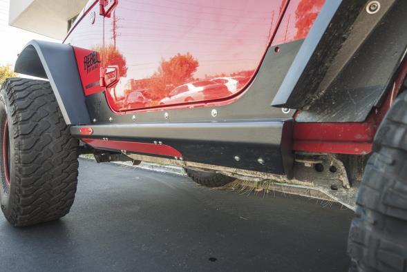
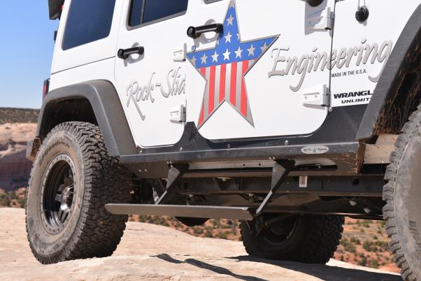
1 JEEP JK4 STEP SLIDER INSTALLATION BD-SS-100-JK4

2 PARTS LIST QTY DESCRIPTION 1 Drivers Side Slider Assembly 1 Passenger Side Slider Assembly 1 Wiring Harness and Fuse 1 Double Sided Sticky Squares and Alcohol Pad 1 Cut Off Switch 1 Anti-Seize Packet 1 Control Box 2 Aluminum Spacers 2 Large Washers 2 Grip Tape Strips 2 130mm Bolts 4 Actuating Magnets and Door Sensors 10 5/16 Washers 10 Aluminum Nutserts 10 5/16 SS Button Head Bolts 10 5/16 Stainless Steel Washers *Optional: 2 LED Light Strips TURN OFF YOUR STEP SLIDERS WHILE WHEELING TO PREVENT DAMAGE
 4) DO NOT REMOVE THESE BOLTS!")
 DO NOT completely tighten the bolts, but leave them loose to reflect the same looseness of the 2 rear bolts so you can fit")
3 STEP SLIDER INSTALLATION 1) Remove the stock rocker guards if equipped 2) Remove the front body bolts on the driver and passenger side (under the front door) 3) Loosen the rear body bolts (under rear passenger doors) 4) DO NOT REMOVE THESE BOLTS! You will need these bolts to support the slider you are about to put into place on the Jeep REAR FRONT 5) Replace the front body bolts on the driver and passenger sides with the 130mm bolt, aluminum spacer, and large washer in same sequence as the picture below indicates a) DO NOT completely tighten the bolts, but leave them loose to reflect the same looseness of the 2 rear bolts so you can fit the slider forks into these slots 6) Move the slider into it s position on the Jeep a) You may want some help so that you can support the weight of the slider b) Take extra care when positioning the slider on the Jeep to prevent any scratching or marring of the painted surface
 Tighten all body mount bolts to help bring the slider into position on the Jeep 10) This will be the final position of the slider so verify it s straight,")
4 7) Insert the 3 slider forks into the 3 body mount bolt slots a) The slider should fit tight to the Jeep s rocker side 8) The top side of the slider should be at a flat 90 degree angle even with the front and rear wheel wells of the Jeep 9) Tighten all body mount bolts to help bring the slider into position on the Jeep 10) This will be the final position of the slider so verify it s straight, level, even on both sides and you are satisfied with the slider s layout 11) Carefully drill a 7/32 pilot hole into the center of the holes on the slider into the Jeep s rocker side **Word from a mechanic: I found that a 3-step drilling procedure worked best. First lightly center punch, then use an 1/8th inch drill for the first pilot hole. All drills tend to walk so the first drill should be small enough to not walk out of the center punch s dimple. After this the sliders can be removed. The next drill size can be your recommended 7/32 but for the life of me I can t figure out what s so critical with this size other than it should be considerably smaller than the finish size of the 17/32 hole. The relatively large final size makes it hard to drill cleanly with a hand drill in the thin metal of the body panel. For those not experienced with this, the drill will tend to draw itself into the hole and stall once it goes through. a) The body sides are very thin metal so let the drill bit do the work. Don t push too hard on the drill or possible sheet metal damages may occur 12) Loosen the body mount bolts and remove the slider from the Jeep a) You may want some help so that you can support the weight of the slider 13) From the center of the pilot hole, step up the hole size using a 17/32 bit to create a finish hole that will be used to install the nutserts 14) Install 5 nutserts per side in the holes that were just drilled into the body of the Jeep a) We suggest using a crimping tool to optimize the integrity of the nutserts to support the slider 15) If no crimping tool is available, follow these instructions a) Install by using a 5/16 x1.125 minimum length bolt with a 3/8 nut b) Put a small amount of grease on the bolt to reduce friction c) Hold the nut steady with an end wrench so the flange of the insert is flush against the body panel d) Tighten the bolt against the nut to crimp the nutsert into place e) If the nutsert is rotating, place a star-lock washer between the 3/8 nut and nutsert f) Once the nutsert is crimped into place completely back out the bolt g) If the nutsert ever breaks loose and spins, repeat the process and crimp it tighter to prevent spinning (Nutserts that have been installed correctly)
 Attach the slider to the rocker face using the 5/16 button head bolts & washers 19) Start from the center of the slider and work out towards the ends 20)")
5 16) Lift the slider into its final position by inserting the 3 forks on the slider onto the 3 body mount bolts and aligning it against the Jeep rocker face 17) Make sure the actuator wire is free from being pinched between the frame 18) Attach the slider to the rocker face using the 5/16 button head bolts & washers 19) Start from the center of the slider and work out towards the ends 20) Apply a small amount of anti-seize to the threads of each bolt 21) You will be using 5 bolts/washers per side a) We recommend tightening the button heads by hand to prevent any damage to the head of the bolt 22) Tighten the body mount bolts beneath the Jeep to fully secure the slider 23) Make sure the spacer is in between the body and the slider on the front body mount 24) The body mount bolts need to be SNUG to the Jeep frame but DO NOT OVER TIGHTEN the body mount bolts. Over tightening these bolts could create a friction point causing the slider to not operate optimally 25) Double check all bolts to verify components and hardware are installed correctly and securely to the Jeep ***Please note: Expect some variance in parts that may require you to adjust the tension of bolts to make parts fit correctly and properly. Once all parts are installed, we suggest then fully tightening all bolts again to fit securely*** WIRING HARNESS INSTALL Step Slider Wiring Diagram Driver Side Wire Color Passenger Side Wire Color Front Door Sensor Orange/Yellow Front Door Sensor Green/Gray Rear Door Sensor Orange/Pink Rear Door Sensor Blue/White Driver LED Light Brown/Tan Passenger LED Light Pink/Tan Driver Actuator Red/Black Passenger Actuator Red/Black


6 **WARNING** REMOVE FUSE FROM WIRING HARNESS PRIOR TO INSTALLATION! CONNECTING THE HARNESS TO THE POWER SOURCE WITH THE FUSE ATTACHED WILL SHORT OUT THE WIRING HARNESS NEVER ALLOW THE DOOR SENSOR TO COME INTO DIRECT CONTACT WITH THE ACTUATING MAGNET. THIS WILL DESTROY THE SENSOR MAKING IT UNUSABLE Remove the B pillar covers on both driver and passenger and driver sides Roll the carpet back underneath the rear seat to expose the floor boards Position the control box under the rear seat on the passenger side It s recommended that you mount the control box under the rear passenger seat because it s out of sight and in a secure location so it will not come into contact with anything or be kicked by a rear seat passenger (see below) Plug the harness into the control box and lay the harness wire into position in the Jeep starting on the rear passenger side You will want to divide the harness between the rear seats, the front passenger seat and finish with the driver door. This will reveal how you will be able to conceal the harness under the carpet when you're done. Once the harness is positioned in its proposed layout you will need to gain access to the slider outside the Jeep to power the slider. Starting on the rear passenger side, locate the drain plug and drill a small hole into it to allow you to run the actuator wires to the slider (see below) Once the actuator is run to the slider you can put some silicon sealant around the drilled hole to prevent any elements from entering, but it s not required

7 Route the actuator wire around the backside of the slider and plug the passenger side red/black connector into the slider Actuator wire must be wired around the backside of slider so it s protected from the elements and will not be severed off during off-road activity Secure wires to minimize slack so they are protected. We recommend pulling the excess back through the hole and storing it under the carpet for protection. *Optional: The pink/tan wire is used if LED light package is being installed. Run these wires down the same hole you ran the actuator wire and and finish installing later. Inside the Jeep, route the rear passenger door sensor wire along the doorframe; and using a sticky pad, mount the sensor underneath the door latch Connect the blue/white wire to the door sensor Place a small piece of electrical tape on the sensor wire to secure (see below) While moving to the front passenger door, run the harness along the side of the Jeep s tub and route the front passenger door sensor wire up the B pillar of passenger door; and using a sticky pad, mount the sensor underneath the door latch Connect the green/grey wire to door sensor Place a small piece of electrical tape on the sensor wire to secure Returning to the backseat, locate the drain plug on the rear driver side and drill a small hole into it to allow you to run the actuator wires to the slider Once the actuator is run to the slider you can put some silicon sealant around the drilled hole to prevent any elements from entering, but it s not required Route the actuator wire around the backside of the slider and plug the driver side red/black connector into the slider Actuator wire must be wired around the backside of slider so it s protected from the elements and will not be severed off during off-road activity Secure wires to minimize slack so they are protected. We recommend zip ties *Optional: The brown/tan wire is used if LED light package is being installed Route the rear driver door sensor wire along the doorframe; and using a sticky pad, mount the sensor underneath the door latch Connect the orange/pink wire to the door sensor on the rear door Place a small piece of electrical tape on the sensor wire to secure Continue to route the harness wires along the lower doorframe on the tub, and just like performed on the passenger side route the door sensor wire along the B pillar up the doorframe and using another sticky pad, mount the sensor below the door hatch. Connect the orange/yellow wire to the door sensor on the front door


8 Place a small piece of electrical tape on the sensor wire to secure Remove the driver side dash panel and drill a 18mm hole in the panel to accommodate the cutoff switch You can mount the cutoff switch in multiple positions. We recommend the dash panel simply for the ease off access (see below) Mount the ground from the cutoff switch to a metal surface behind dash panel (below) ** THE WIRING SCHEMATIC TO THE BACK OF THE CUTOFF IS RED RED BLACK, IF LIGHT STAYS ON SWAP RED UNTIL.** Route the cutoff switch wires by running the POS+ and NEG- wires up the driver side A pillar and plug them into the back of the cutoff switch Route the remaining POS+ and NEG- wires through the firewall on the driver s side into the engine compartment. Make sure there is NO INTERFERENCE with any of the pedal linkage under the dash Route these wires along the firewall up to the battery compartment Secure the wires using the harness attached to the firewall Attach the NEG- to the NEG- side of the battery Attach the POS+ to the POS+ side of the battery Position the actuating magnets on the catch side of each door

9 Make sure the actuating magnets are in perfect line with the sensors **DO NOT allow the magnet and sensor to come into direct contact. This will destroy the sensor making it unusable** Once that proper placement is achieved we recommend using a permanent marker to outline the magnet on the door. Re-check all wires to make sure they are completely secure and free from coming into contact with any moving part to prevent system damage due to a cut wire Reinstall all internal plastic and carpet pieces that were removed. Make sure that all wires are tucked back and out of heavy traffic areas on the floor. Route them toward the furthest back area underneath the rear seat Close all doors Insert the fuse into the holder on the POS+ side of the battery Test all doors to make sure the step deploys each time a door is opened, and retracts when the door is closed MAINTENANCE OF THE STEP SLIDER Please note the slider is a mechanical mechanism that requires maintenance to operate properly. To keep the slider operating at an optimal level it needs to be maintained with lubrication. We recommend using a Teflon based lubrication on the 7 indicated points below to keep the slider operating smoothly. A good rule of thumb is every month. Heavy trail use will increase the frequency in lubrication. LUBRICATE THE HINGE POINTS: 2 - HINGE POINTS ON THE STEP PORTION ON THE BACK SIDE 4 - HINGE POINTS IN THE BODY OF THE SLIDER (ALUMINUM BLOCKS) 1 - LUBRICATE THE MOTOR SHAFT LIGHTLY SO IT CAN TRANSFER THE LUBRICANT TO THE O-RINGS AS IT RETRACTS
10 TROUBLE SHOOTING/FRICTION POINTS The slider is powered by the Jeep s battery when engine is off and powered by the Jeep s engine while the vehicle is running. This will cause the slider to operate at different speeds depending on the Jeep engine is running or not. If you feel the slider is sticking at certain points or the motor is stressing it may be possible a friction point has developed during the install due to a variance in the slider or Jeep construction To identify a friction point that may be stressing the slider motor, look at the slider from outside the jeep and open and shut the Jeep door a couple of times and study the way the slider operates. Look at the slider for wear in the powder coating. The slider leaves our manufacturing facility with a perfect powder coating so if you see a spot on the slider that has scratches or the powder coating shows a blemish; that s a good indication of a friction point. Using a file or other grinding tool to smooth over a small area on the slider can alleviate this problem.
JEEP JK4 STEP SLIDER INSTALLATION BD-SS-100-JK4
 JEEP JK4 STEP SLIDER INSTALLATION BD-SS-100-JK4 PARTS LIST QTY DESCRIPTION 1 Drivers Side Slider Assembly 1 Passenger Side Slider Assembly 1 Wiring Harness and Fuse 1 Double Sided Sticky Squares and Alcohol
JEEP JK4 STEP SLIDER INSTALLATION BD-SS-200-JK4 / BD-SS-201-JK4
 JEEP JK4 STEP SLIDER INSTALLATION BD-SS-200-JK4 / BD-SS-201-JK4 Installaton Instructon RSEI 106 P A R TS L IST QTY DESCRIPTION 1 Drivers Side Slider Assembly 1 Passenger Side Slider Assembly 1 Wiring Harness
TJ YJ LJ STEP SLIDER INSTALLATION
 TJ YJ LJ STEP SLIDER INSTALLATION BD-SS-100-TJ, BD-SS-100-YJ, BD-SS-100-LJ PARTS LIST QTY DESCRIPTION 1 Drivers Side Slider Assembly 1 Passenger Side Slider Assembly 1 Wiring Harness 1 Double Sided Sticky
Ram Step Slider Installation BD-SS-100-RAM,.BD-SS-101-RAM. Installation Instruction RSEI 108
 Ram Step Slider Installation BD-SS-100-RAM,.BD-SS-101-RAM PARTS LIST DESCRIPTION 1 Drivers Side Slider Assembly 1 Passenger Side Slider Assembly 1 Wiring Harness and Fuse 1 Double Sided S cky Squares and
R-SE JK 4 DOOR Step Slider Install Instructions. *If any parts listed are missing or damages please call prior to install.
 R-SE JK 4 DOOR Step Slider Install Instructions Parts List: 1 Divers side slider assembly 1 Passenger side slider assembly 1 wiring harness 1 control box 2 spacers 2 LED lights (optional) 10 SS Button
ROCK-SLIDE ENGINEERING. Auto Step PART# BD-AS-100-JK4 CONGRATULATIONS ON YOUR PURCHASE OF THE AUTO STEP!
 Auto Step PART# BD-AS-100-JK4 CONGRATULATIONS ON YOUR PURCHASE OF THE AUTO STEP! DESIGNED TO BE FUNCTIONAL, TOUGH, AND DURABLE WHILE PERMITTING YOU TO GET IN AND OUT OF YOUR VEHICLE WITH EASE. IMPORTANT
INSTALLATION MANUAL STEP SLIDER BD-SS-200-JK4. Made in the USA. Front Bracket Middle Bracket Rear Bracket. Tools Required
 Made in the USA INSTALLATION MANUAL STEP SLIDER BD-SS-200-JK4 Description Quantity Electric Step Slider (Pair) 2 Front Bracket Middle Bracket Rear Bracket Bump stop plate with VHB backing 2 Wiring harness
2005+ Roll Bar (Mm5RB-20.1 to -20.6) Recommended Center punch 1/8" pilot drill 1-3/4" Hole saw 2" Hole saw
 Recommended Center punch 1/8 pilot drill 1-3/4 Hole saw 2 Hole saw") 3430 Sacramento Dr., Unit D San Luis Obispo, CA 93401 Telephone: 805/544-8748 Fax: 805/544-8645 www.maximummotorsports.com 2005+ Roll Bar (Mm5RB-20.1 to -20.6) Recommended Center punch 1/8" pilot drill
3430 Sacramento Dr., Unit D San Luis Obispo, CA 93401 Telephone: 805/544-8748 Fax: 805/544-8645 www.maximummotorsports.com 2005+ Roll Bar (Mm5RB-20.1 to -20.6) Recommended Center punch 1/8" pilot drill
Stay-IN-Play with Panic Stop Braking
 INSTALLATION INSTRUCTIONS TOWED VEHICLE BRAKING SYSTEM Stay-IN-Play with Panic Stop Braking SMI Manufacturing, Inc. P.O. Box 14040 Evansville, IN 47728 1-800-893-3763 www.smibrake.com SIP0906 Model SIP0603
Installation Instructions
 Installation Instructions Jeep JK Unlimited (2007 Present) Mounting Bracket and Air Line System Kit for ARB On-Board Twin Air Compressor (CKMTA12) Made in the USA Kit Contents: 1 Bracket for ARB Compressor
Your Legal Fuel Tank Source.
 February 23, 2015 IS# 808 Page 1 of 13 THANK YOU FOR PURCHASING A TRANSFER FLOW 40 GALLON TOOLBOX REFUELING SYSTEM. PLEASE READ THE FOLLOWING PROCEDURES CAREFULLY BEFORE STARTING THE INSTALLATION. CAUTION:
POWERED RUNNING BOARDS INSTALLATION MANUAL
 POWE RUNNING BOARDS INSTALLATION MANUAL Level of Difficulty Moderate Parts List 1 Driver / left running board* 1 Passenger / right running board* 4 Mounting bracket, standard 2 Mounting bracket, middle
Dodge Cummins Positive Air Shutoff
 1 INSTALL MANUAL 2010-2012 6.7 Dodge Cummins Positive Air Shutoff P/N# 1036722 P/N# 1036722-M UPLEASE READ ALL INSTRUCTIONS BEFORE INSTALLATION An Information decal has been provided in this kit. This
LoD Offroad. Jeep JK Door Linked Rear Bumper with Tire Carrier Installation Instructions
 LoD Offroad Jeep JK Door Linked Rear Bumper with Tire Carrier Installation Instructions Please read through the instructions before beginning any part of the installation process. Packaging List: 1-Rear
Applicable to the Following Part Numbers. Notes and Maintenance. Torque Specifications. Metric SAE. Use above torque setting unless otherwise noted
 INSTALLATION MANUAL Level of Difficulty Moderate This is the second first of two of two manuals required to complete this installation. The first second manual manual is is included with with your mounting
Toyota Tacoma Winch Mount Bumper Installation Instructions Tools Required: Transmission cooler relocation brackets Torque Wrench
 2016-2017 Toyota Tacoma Winch Mount Bumper Installation Instructions Tools Required: Items Included: Small flat head screw driver Winch Mount Ratchet, 10mm, 12mm, 14mm, 17mm & Skid Plate 19mm sockets Transmission
AMP RESEARCH TECH SUPPORT (Press 2) Monday - Friday, 6:00 AM - 5:00 PM PST
 Monday - Friday, 6:00 AM - 5:00 PM PST") APPLICATION AMP Part # Jeep Wrangler Unlimited (JK) 2007 2017 78122-01A (-Door Only) INSTALLATION TIME 3-5 Hours Professional installation recommended SKILL LEVEL 1 2 3 = Experienced TOOLS REQUIRED q 13
APPLICATION AMP Part # Jeep Wrangler Unlimited (JK) 2007 2017 78122-01A (-Door Only) INSTALLATION TIME 3-5 Hours Professional installation recommended SKILL LEVEL 1 2 3 = Experienced TOOLS REQUIRED q 13
I N S T A L L A T I O N G U I D E
 I N S T A L L A T I O N G U I D E APPLICATION AMP Part # Jeep Wrangler Unlimited (JK) 2007 2017 78122-01A (4-Door Only) INSTALLATION TIME 3-5 Hours Professional installation recommended SKILL LEVEL 1 2
Installation Instructions
 Installation Instructions Jeep JK 2-Door (2011 Present) Mounting Bracket and Air Line System Kit for ARB On-Board Twin Air Compressor (CKMTA12) Made in the USA Kit Contents: 1 Flat Bracket 1 Formed Bracket
C15C C15C. Page 1 of 20
 2 x Lid Front Hinge 1135 8 x M8 Bolt 8 x M8 Washer (3mm Thick) 4 x M6 Large washers 4 x M6 Spring washers 4 x M6 x 40mm Bolts 6 x M6 20mm Bolts 6 x M6 Washers 20 x Screws 2 x Lid mount gas strut bracket
Automatic Roof Hatch Opener
 Automatic Roof Hatch Opener Installation Guide REQUIRED TOOLS (These tools are required to complete the installation) Cordless Drill 1/8 1/4 Drill Bits 1/8 Pin Punch #2 Philips Bit Rachet Sharpie Hammer
INSTALLATION INSTRUCTIONS
 INSTALLATION INSTRUCTIONS FORCE 10 SPORT R1 REAR DISC CONVERSION KIT A126-50 2005-10 Chevrolet Silverado and GMC Sierra Thank you for choosing STAINLESS STEEL BRAKES CORPORATION for your braking needs.
LoD Offroad. Jeep JK Rear Bumper with Tire Carrier Installation Instructions
 LoD Offroad Jeep JK Rear Bumper with Tire Carrier Installation Instructions Please read through the instructions before beginning any part of the installation process. Packaging List: 1-Rear Bumper 1-Tire
LPE C5 Battery Relocation Kit
 LPE C5 Battery Relocation Kit The LPE C5 Corvette battery relocation kit improves vehicle weight distribution by moving weight to the rear of the vehicle. The improved weight distribution increases traction
Installation Instructions
 Installation Instructions Automatic Retracting Running Board Vehicle Application Ford F150 Supercrew 2001-2003 (2004 Heritage) Part Number: 75111-01 www.bestop.com - We re here to help! Visit our web site
CALIFORNIA TRIMMER MOWER MAINTENANCE MANUAL
 CALIFORNIA TRIMMER MOWER MAINTENANCE MANUAL 2 Table of Contents Section 1: General Information Page Handle Assembly Instructions 4 Maintenance All Models 6 Oil Change Procedures All Models 9 Height Adjustment
Before starting installation
 Before starting installation The load rating for these tire-can/tire carriers is a MAXIMUM of 175 lbs. Please be aware that some tire and wheel combinations along with gas cans and hi-lift jacks can exceed
INSTALLATION INSTRUCTIONS
 INSTALLATION INSTRUCTIONS POWER FRONT DISC CONVERSION KIT A126-7 1963-66 CHEVY C10 PICKUP NON-POWER FRONT DISC CONVERSION KIT A126-8 1963-72 CHEVY C10 PICKUP Thank you for choosing STAINLESS STEEL BRAKES
JEEP Wrangler JK/JKU Swing-A-Way Tire Carrier/RotoPpax WARNINGS/CAUTIONS NOTE. INSTALLATION INSTRUCTIONS 2 Door Models 85209
 JEEP Wrangler JK/JKU Swing-A-Way Tire Carrier/RotoPpax 2007-2017 INSTALLATION INSTRUCTIONS Item Kit No. 2 Door Models 85209 4 Door Models 85209 WARNINGS/CAUTIONS These instructions are for both the can
2015+ S550 MUSTANG Battery Relocation Kit WR-BTRYRELOKIT-LH WR-BTRYRELOKIT-RH
 2015+ S550 MUSTANG Battery Relocation Kit WR-BTRYRELOKIT-LH WR-BTRYRELOKIT-RH The Watson Racing Battery Relocation Kit is NOT designed to protect you in the case of an accident, and therefore is INTENDED
INSTALLATION GUIDE. AMP RESEARCH TECH SUPPORT (Press 2) Monday - Friday, 6:00 AM - 5:00 PM PST
 Monday - Friday, 6:00 AM - 5:00 PM PST") INSTALLATION GUIDE APPLICATION AMP Part # Jeep Wrangler Unlimited (JK) 2007 2015 75122-01A (-Door Only) INSTALLATION TIME 3-5 Hours Professional installation recommended SKILL LEVEL 1 2 3 = Experienced
INSTALLATION GUIDE APPLICATION AMP Part # Jeep Wrangler Unlimited (JK) 2007 2015 75122-01A (-Door Only) INSTALLATION TIME 3-5 Hours Professional installation recommended SKILL LEVEL 1 2 3 = Experienced
RIGGING THE FLIGHT CONTROLS
 RIGGING THE FLIGHT CONTROLS Rigging refers to the installation and adjustment of the rods that move flight surfaces in response to inputs from the controls of the helicopter. These rods are cut to length,
Ram 1500 Crew Cab A Ram 2500/3500 Crew Cab A
 I N S T A L L A T I O N G U I D E APPLICATION AMP Part # Ram 1500 Crew Cab 2013-2015 77138-01A Ram 2500/3500 Crew Cab 2013-2015 77138-01A Note:The application works only on the Crew Cab model Vehicles.
INSTALLATION MANUAL. Middle. Def tank. Standard. Middle. Standard. Def tank WARNING. Level of Difficulty CAUTION. Parts List.
 INSTALLATION MANUAL 3025101 Level of Difficulty Moderate This is the second first of two of two manuals required to complete this installation. The first second manual manual is is included with with your
JK REAR BUMPER AND TIRE CARRIER
 JK REAR BUMPER AND TIRE CARRIER Installation Guide AEV30105AA (Updated 5/10/10) Page 1 of 20 Page 2 of 20 EXPLODED VIEW PLEASE READ BEFORE YOU START IN ORDER TO INSTALL THIS PART PROPERLY YOU OR YOUR INSTALLER
STEP SLIDER MOTOR REPLACEMENT INSTALLATION
 STEP SLIDER MOTOR REPLACEMENT INSTALLATION Important Before installation, make sure control box has a serial number on the circuit board. Updated control boxes all have serial numbers. In order to verify,
Classic Light Bar Mustang
 Classic Light Bar 2005-2012 Mustang Note: Read installation instructions before starting. Component List: 1 Light Bar Part #110000 1 Driver Side Bracket w/set Screw Part #115003 1 Passenger Side Bracket
INSTALL MANUAL D o d g e 1 2 v 6 B T A PLEASE READ ALL INSTRUCTIONS BEFORE INSTALLATION.
 PN#1045310 12V Dodge Twin Turbo Kit (I-00273) 1 INSTALL MANUAL BD Twin Turbo Kit 1994-1 9 9 8 D o d g e 1 2 v 6 B T A Part# 1045310 PLEASE READ ALL INSTRUCTIONS BEFORE INSTALLATION. * Picture as shown
I N S T A L L A T I O N G U I D E
 I N S T A L L A T I O N G U I D E APPLICATION MODEL YR PART # Dodge Ram Regular Cab * 1500 2013-2014 76138-01A REV B Dodge Ram Quad Cab * 1500 2013-2014 76138-01A REV B Dodge Ram Crew Cab 1500 2013-2014
Combine Cover Manual
 Combine Cover Manual Installation Instructions Page 26 Operating Instructions Page 7 Warranty Page 7 Trouble Shooting Page 8 10 For Big Top Extension Model s: Case I.H. 8010, 8120 Please forward onto Customer
2015+ HELLCAT 6.2L HEMI System vehicle specific plate system xx
 These installation instructions will guide you through installing the Nitrous Outlet 2015+ Hellcat 6.2L Hemi Vehicle Specific Plate System on your vehicle. Before you get started, remember to never use
Tusk UTV Horn & Signal Kit Installation Instructions
 Tusk UTV Horn & Signal Kit Installation Instructions The Tusk UTV signal kit is designed to be a simple way to provide front and rear turn signals, license plate mount with light, horn, and rearview mirrors
Installation Instructions
 Parts Installation Instructions DESCRIPTION PART # QTY A Alignment Tab PN ESB101 1 B Drill Guide PN ESB102 1 C Actuator Cable Assembly PN ESB103 1 C1 72 Actuator Cable 1 C2 5/16 Jam Nut 1 C3 Star Washer
Roll Bar (MMRB-6.1 to -6.7)
") 3430 Sacramento Dr., Unit D San Luis Obispo, CA 93401 Telephone: 805/544-8748 Fax: 805/544-8645 www.maximummotorsports.com 1994-04 Roll Bar (MMRB-6.1 to -6.7) NOTE: These instructions cover Roll Bars with
3430 Sacramento Dr., Unit D San Luis Obispo, CA 93401 Telephone: 805/544-8748 Fax: 805/544-8645 www.maximummotorsports.com 1994-04 Roll Bar (MMRB-6.1 to -6.7) NOTE: These instructions cover Roll Bars with
INSTALLATION INSTRUCTIONS
 INSTALLATION INSTRUCTIONS FX4 ELITE REAR DISC CONVERSION KITS WITH INTERNAL PARKING BRAKE A110-14, A111-25, A111-29 for FORD 8" & 9" REAR ENDS Thank you for choosing STAINLESS STEEL BRAKES CORPORATION
1464. Interior Installation. Cover Rear Seat Support Cut the vinyl to approximately the size of the rear seat support.
 Chapter 37 (Video Clip 37) - Interior Installation 1464. Interior Installation Cover Rear Seat Support 1465. Cut the vinyl to approximately the size of the rear seat support. 1466. Make a dry fit of the
Thank you for purchasing the Craven Speed FlexPod Complete Gauge Pod Kit For R56, R58, R59, R60 with Refresh Engines (2011+)
") Thank you for purchasing the Craven Speed FlexPod Complete Gauge Pod Kit For R56, R58, R59, R60 with Refresh Engines (2011+) Before You Start Please read instructions completely before installing. These
Thank you for purchasing the Craven Speed FlexPod Complete Gauge Pod Kit For R56, R58, R59, R60 with Refresh Engines (2011+) Before You Start Please read instructions completely before installing. These
LGT-311L Bumper LED Light Kit EZ-Go RXV Installation Instructions
 LGT-311L Bumper LED Light Kit EZ-Go RXV Installation Instructions Caution: Please read through the instructions carefully. Before starting this project, remove the system s positive and negative connections
GM 6.6L (LML) Duramax Positive Air Shutoff 2.5 CAC TUBES
 Duramax Positive Air Shutoff 2.5 CAC TUBES") 8 April 2013 1036713 GM/Chevy Duramax 2011-2013 (LML) Positive Air Shutoff 1 2011-2013 GM 6.6L (LML) Duramax Positive Air Shutoff 2.5 CAC TUBES P/N# 1036713 P/N# 1036713-M UPLEASE READ ALL INSTRUCTIONS
8 April 2013 1036713 GM/Chevy Duramax 2011-2013 (LML) Positive Air Shutoff 1 2011-2013 GM 6.6L (LML) Duramax Positive Air Shutoff 2.5 CAC TUBES P/N# 1036713 P/N# 1036713-M UPLEASE READ ALL INSTRUCTIONS
LGT-312L E-Z-Go TXT Light Bar Bumper Kit Installation Instructions
 LGT-312L E-Z-Go TXT 2014+ Light Bar Bumper Kit Installation Instructions Caution: Please read through the instructions carefully. Before starting this project, remove the system s positive and negative
/ GMC SIERRA 2500 / 3500 START HERE BEFORE YOU BEGIN STEP 2
 2015-2016 CHEVROLET SILVERADO 2500 / 3500 / 2015-2016 GMC SIERRA 2500 / 3500 Z321221 / Z321221-KIT FRONT BUMPER LED LIGHT MOUNTS Parts included - (1) Driver Side Light Mount Bumper Bracket - (1) Passenger
2. With the rear door open remove pull-style clip from the passenger side just below the door latch.
 LoD Offroad FJ Cruiser Rear Bumper with Tire Carrier Installation Instructions 1. Begin with removing factory spare from the rear door. 2. With the rear door open remove pull-style clip from the passenger
WRX/STI Engine Oil Cooler
 2002-14 WRX/STI Engine Oil Cooler 2014-04-21 Thank you for purchasing this PERRIN product for your car! Installation of this product should only be performed by persons experienced with installation of
Perfect Park 7000 Installation & Unloading Instructions Operating Manual
 Perfect Park 7000 Installation & Unloading Instructions Operating Manual 1) Always file a claim with the truck line if the lift has been damaged! (If you don t originally notice the damage, but find some
67-70 Cougar Rack Kit Instructions # &
 67-70 Cougar Rack Kit Instructions # 8011950-01 & 8011940-01 Unisteer offers a limited warranty against all manufacturer defects of their kits and supplied parts. Unisteer will not honor any warranty on
Drag Race Roll Bar (MMRB-6, -7)
") 3430 Sacramento Dr., Unit D San Luis Obispo, CA 93401 Telephone: 805/544-8748 Fax: 805/544-8645 www.maximummotorsports.com 1994-04 Drag Race Roll Bar (MMRB-6, -7) The Maximum Motorsports 6-point Drag Race
3430 Sacramento Dr., Unit D San Luis Obispo, CA 93401 Telephone: 805/544-8748 Fax: 805/544-8645 www.maximummotorsports.com 1994-04 Drag Race Roll Bar (MMRB-6, -7) The Maximum Motorsports 6-point Drag Race
INSTALLATION GUIDE. JK Rear bumper & tire carrier. AEV30105AC Last Updated: 10/11/16 US PATENT: D642,502 ; D
 AEV30105AC Last Updated: 10/11/16 JK Rear bumper & tire carrier US PATENT: D642,502 ; D633.024 INSTALLATION GUIDE PLEASE READ BEFORE YOU START TO GUARANTEE A QUALITY INSTALLATION, WE RECOMMEND READING
Adjustable Light Kits E-Z-Go TXT All Models Installation Instructions
 Adjustable Light Kits E-Z-Go TXT All Models 1996-2013 Installation Instructions Caution: Please read through the instructions carefully. Before starting this project, remove the system s positive and negative
Deuce/Ace Installation Instructions
 HARDWARE KIT: Upper Mounting Plate: 2-7/16" (11mm) X 3.5" bolts 2-7/16" flange nuts 2-2" spacers 2-7/16" trim cap mounting washers 2 - plastic trim caps TOOLS NEEDED: safety glasses wrenches 16mm or 5/8"
D40C HINGE # x Support Plate x M8 Bolt 8 x M8 Washer 6 x M6 20mm Bolts 6 x M6 Washers 19 x Screws
 HINGE # 1017 2 x Support Plate 1018 8 x M8 Bolt 8 x M8 Washer 6 x M6 20mm Bolts 6 x M6 Washers 19 x Screws 2 x Lid mount gas strut bracket 1041 2 x Self tap strut mount 1040 1 x Central Lock bracket 1510
Bottom Mount Seat Mount Installation & Wiring Instructions
 E81/E87/E90/E91/E92/F22/F30/F31/F32/F80/F82/F87 (and other cars with the same sliders) Bottom Mount Seat Mount Installation & Wiring Instructions These instructions assume a basic comfort with crimping
Ford 7.3L Powerstroke Positive Air Shutoff
 24 October 2012 Ford 7.3L 1999.5-2003 Positive Air Shutoff 1 1999.5-2003 Ford 7.3L Powerstroke Positive Air Shutoff P/N# 1036700 P/N# 1036700-M UPLEASE READ ALL INSTRUCTIONS BEFORE INSTALLATION 24 October
INSTALLATION INSTRUCTIONS Mitsubishi Lancer Evolution VIII / IX Fuel Surge Tank Kit Document#
 d INSTALLATION INSTRUCTIONS Mitsubishi Lancer Evolution VIII / IX Fuel Surge Tank Kit Document# 19-0077 Brie Tech Support: info@radiumauto.com CAUTION: Exercise extreme caution when working with the fuel
Deegan 38 HD Rock Sliders w/ LED Rock Lights (07-18 Wrangler JKU)
") Installation Time: 2-3 Hours Deegan 38 HD Rock Sliders w/ LED Rock Lights (07-18 Wrangler JKU) Note: This kit comes with everything you need to wire the lights with a switch in the cab. However, I recommend
Installation Time: 2-3 Hours Deegan 38 HD Rock Sliders w/ LED Rock Lights (07-18 Wrangler JKU) Note: This kit comes with everything you need to wire the lights with a switch in the cab. However, I recommend
INSTALLATION INSTRUCTIONS
 INSTALLATION INSTRUCTIONS REAR DISC BRAKE CONVERSION KIT A126-1 1973-87 CHEVROLET 1/2 TON 2WD Thank you for choosing STAINLESS STEEL BRAKES CORPORATION for your braking needs. Pleases take the time to
General Information. Notations and Conventions. Compatibility Check. Kit Description. Call-Outs. Part Lists Great Plains Manufacturing, Inc.
 Part Lists Great Plains Manufacturing, Inc. 1 Installation Instructions Loup Shaft Monitor Used with Drill models: Compatible with most 1995 and later, two- and three-box drills with 5 8 -inch square main
INSTALLATION GUIDE. AMP RESEARCH TECH SUPPORT (Press 2) Monday - Friday, 6:00 AM - 5:00 PM PST
 Monday - Friday, 6:00 AM - 5:00 PM PST") INSTALLATION GUIDE APPLICATION AMP Part # Jeep Wrangler Unlimited (JK) 2007 up 75121-01A 2-Door INSTALLATION TIME 3-5 Hours Professional installation recommended SKILL LEVEL 1 2 3 = Experienced TOOLS REQUIRED
INSTALLATION GUIDE APPLICATION AMP Part # Jeep Wrangler Unlimited (JK) 2007 up 75121-01A 2-Door INSTALLATION TIME 3-5 Hours Professional installation recommended SKILL LEVEL 1 2 3 = Experienced TOOLS REQUIRED
Installation Guide CLAAS Lexion Combines with 9 inch Elevators
 Installation Guide CLAAS Lexion Combines with 9 inch Elevators 955614_01 4/17 1 Table of Contents System Overview 3 Quick Start Guide 4 Flow Sensor Installation 5 Hydraulic Elevator Adjustment Kit Installation
INSTALLATION INSTRUCTIONS
 INSTALLATION INSTRUCTIONS PERFORMANCE AT THE WHEELS KIT W155-5 CHRYSLER 8 3 /4" & 9 3 /4" REAR AXLES Thank you for choosing STAINLESS STEEL BRAKES CORPORATION for your braking needs. Please take the time
Ford 6.7L Powerstroke Positive Air Shutoff
 8 April 2013 Ford 6.7L 2011-2012 Positive Air Shutoff 1 2011-2012 Ford 6.7L Powerstroke Positive Air Shutoff P/N# 1036703 P/N# 1036703-M UPLEASE READ ALL INSTRUCTIONS BEFORE INSTALLATION BD Engine Brake
½ DODGE CUMMINS
 19 October 2012 2003-04½ Dodge Cummins FlowMAX Lift Pump Kit # 1050305B - 1-2003-04½ DODGE CUMMINS BD FlowMax LIFT PUMP KIT Installation Instructions P/N# 1050305B PLEASE READ ALL INSTRUCTIONS CAREFULLY
GM 6.6L (LLY, LZB, LMM) Duramax Positive Air Shutoff 2.5 CAC TUBES
 Duramax Positive Air Shutoff 2.5 CAC TUBES") 8 April 2013 1036712 GM/Chevy Duramax 2004.5-2010 (LLY,LBZ,LMM) Positive Air Shutoff 1 2005-2010 GM 6.6L (LLY, LZB, LMM) Duramax Positive Air Shutoff 2.5 CAC TUBES P/N# 1036712 P/N# 1036712-M UPLEASE READ
8 April 2013 1036712 GM/Chevy Duramax 2004.5-2010 (LLY,LBZ,LMM) Positive Air Shutoff 1 2005-2010 GM 6.6L (LLY, LZB, LMM) Duramax Positive Air Shutoff 2.5 CAC TUBES P/N# 1036712 P/N# 1036712-M UPLEASE READ
3-5 Hours Professional installation recommended
 I N S T A L L A T I O N G U I D E APPLICATION LENGTH MODEL YR PART # Chevrolet Colorado / GMC Canyon - Crew Cab 72 2015-2016 76153-01A Chevrolet Colorado / GMC Canyon - Extended Cab 65 2015-2016 76153-01A
Tail lights. Headlights
 Revised December 2014 02-017 Light Kit will fit Yamaha G-Series* installation instructions included: tools needed: 2 Headlights 2 Tail Lights Wiring Harness Screws Straps Hazard Switch Phillips Head Screw
Go-ped ESR750 / ESR750EX Rear Brake Installation Instructions
 Go-ped ESR750 / ESR750EX Rear Brake Installation Instructions This kit provides all the parts you need to install a rear brake on your ESR750 or ESR750EX. It will not work on an ESR Sport, or other Go-ped
Lethal Performance Dual FPDM Harness Kit Installation
 Lethal Performance Dual FPDM Harness Kit Installation The Lethal Performance Dual FPDM Harness Kit is a plug-and-play modification. Depending on whether you are using the Lethal Performance wire upgrade
STEALTH. The MOST Versatile and Easiest To Use Towed Vehicle Braking System available! NEED HELP? Call WARNING
 0 STEALTH The MOST Versatile and Easiest To Use Towed Vehicle Braking System available! INSTALLATION manual NEED HELP? Call - -00-0- Read all instructions before installing or operating the Stealth. Failure
Tusk Pannier Racks. Instructions and information KLR
 1 Tusk Pannier Racks Instructions and information KLR650 2008 + Congratulations on your purchase of the Tusk Pannier Racks. These racks are made to handle extreme adventure riding, but work great for the
ITEM QTY CHECK PART NUMBER DESCRIPTION
 PART #21128 2010 Camaro Cold Air Induction Stage II PACKING LIST Before installation, use this check list to make sure all necessary parts have been included. ITEM QTY CHECK PART NUMBER DESCRIPTION 1.
Detroit Speed, Inc. Mini Tubs Camaro/Firebird P/N:
 Detroit Speed, Inc. Mini Tubs 1967-1969 Camaro/Firebird P/N: 040401 The Detroit Speed Mini-Tubs are inner wheel housings designed to accommodate a wider wheel and tire package. They are engineered for
Mustang CDC Lightbar (94-04) - Installation Instructions
 - Installation Instructions") Mustang CDC Lightbar (94-04) - Installation Instructions The below installation instructions work for the following products: Classic Design Concepts Mustang Convertible Lightbar (94-04 Carbon Fiber) Classic
Mustang CDC Lightbar (94-04) - Installation Instructions The below installation instructions work for the following products: Classic Design Concepts Mustang Convertible Lightbar (94-04 Carbon Fiber) Classic
3 October 2016 PN# V Dodge Twin Turbo Kit (I-00274) ½ D o d g e 2 4 v I S B
 ½ D o d g e 2 4 v I S B") 3 October 2016 PN#1045320 24V Dodge Twin Turbo Kit (I-00274) 1 DOWNLOAD ENHANCED INSTALL MANUALS AT dieselperformance.com BD Twin Turbo Kit 1998½- 2 0 0 2 D o d g e 2 4 v I S B Part# 1045320 PLEASE READ
3 October 2016 PN#1045320 24V Dodge Twin Turbo Kit (I-00274) 1 DOWNLOAD ENHANCED INSTALL MANUALS AT dieselperformance.com BD Twin Turbo Kit 1998½- 2 0 0 2 D o d g e 2 4 v I S B Part# 1045320 PLEASE READ
INSTALLATION INSTRUCTIONS
 INSTALLATION INSTRUCTIONS Models: 7105 & 7105TK Dodge Ram 1500 ('02 Current) Ram 2500 & 3500 '03 - Current with stock manual mirrors. IF YOU DO NOT CURRENTLY HAVE MANUAL MIRRORS, THE WRONG SET HAS BEEN
Page 1. File: Motolight caliper one-piece Harley Date: 8/15/2006
 Page 1 Harley-Davidson FL Caliper Mount Installation One-piece mounting brackets You should allow about two to three hours for installation. We suggest you use a well-lighted space for installation. PLEASE
GENUINE PARTS INSTALLATION INSTRUCTIONS
 GENUINE PARTS INSTALLATION INSTRUCTIONS DESCRIPTION: APPLICATION: PART NUMBER: Electronic Tailgate Lock Kit Nissan Titan 999M2-W3005 KIT CONTENTS: Item Qty. Part Description Service Part Number A 1 Electronic
INSTALLATION INSTRUCTIONS
 INSTALLATION INSTRUCTIONS REAR DISC CONVERSION KIT A126-2 1988-98 C1500 2WD 10" REAR DRUM Thank you for choosing STAINLESS STEEL BRAKES CORPORATION for your braking needs. Pleases take the time to read
Ford Torino Small Block Rack Kit Instructions
 1968-69 Ford Torino Small Block Rack Kit Instructions 8012290-01 Unisteer offers a limited warranty against all manufacturer defects of their kits and supplied parts. Unisteer will not honor any warranty
INSTALLATION INSTRUCTIONS JEEP 2011-UP JK SECURITY FULL CONSOLE #274
 INSTALLATION INSTRUCTIONS JEEP 2011-UP JK SECURITY FULL CONSOLE #274 PARTS CHECKLIST Tuffy Console #9 Left Front Mounting Bracket #10 Right Front Mounting Bracket #11 Electronics mounting bracket #12 Divider
INSTALLATION MANUAL AP60B INSTALLATION MANUAL
 INSTALLATION MANUAL 2. TOOLS REQUIRED The following is a list of tools required to properly install the cruise control. While this unit may be installed without some of the tools listed, it is recommended
A B C D E F. Tools Required (supplied by others)
") Page 1 of 17 Parts List Below Deck Automatic Retractable Security Cover Kit (1) Tube End Bearing Plate (A) (1) Rope Reel and Cover Drum Motor Assembly (B) (1) Cover Drum (1) Pulley Support Channel (2)
Page 1 of 17 Parts List Below Deck Automatic Retractable Security Cover Kit (1) Tube End Bearing Plate (A) (1) Rope Reel and Cover Drum Motor Assembly (B) (1) Cover Drum (1) Pulley Support Channel (2)
½ DODGE CUMMINS
 7 April 2009 2003-04½ Dodge Cummins FlowMAX Lift Pump Kit # 1050305-1 - 2003-04½ DODGE CUMMINS BD FlowMax LIFT PUMP KIT Installation Instructions P/N# 1050305 PLEASE READ ALL INSTRUCTIONS CAREFULLY BEFORE
Procharger Stage II Intercooled Supercharger System (11-14 GT)
") Procharger Stage II Intercooled Supercharger System (11-14 GT) Installation Time: Approximately one day. Installed on 2012 Mustang GT 5.0/Manual Required Tools 3/8 Socket Set (Standard and Metric) 1/2
Procharger Stage II Intercooled Supercharger System (11-14 GT) Installation Time: Approximately one day. Installed on 2012 Mustang GT 5.0/Manual Required Tools 3/8 Socket Set (Standard and Metric) 1/2
Backside License Plate Mount for Jeep JK Wrangler
 REQUIRED TOOLS 10mm SOCKET 13mm SOCKET 4mm HEX KEY WIRE CRIMPS WIRE STRIPPERS ELECTICAL TAPE SCREW DRIVER KIT CONTAINS BACKSIDE MOUNT LICENSE PLATE BRACKET WITH LEDS PLASTIC PASS-THROUGH GROMMET STAINLESS
Step 6: Remove and save the MAP sensor for later use. Step 7: Remove the passenger side intercooler pipe and the EGR intake manifold.
 LBZ Twin kit Install Step 1: Disconnect both batteries. Step 2: Drain coolant and oil also remove passenger side inner fender. Step 3: Remove intake box and piping. (Remove and save the MAF sensor in the
Switchback Carrier Rack System
 Switchback Carrier Rack System Installation Instructions 1 Rocky Mountain Westy Ph. (970)310-3441 Introduction Thank you for purchasing the Rocky Mountain Westy Switchback Carrier Rack System. We pride
INSTALLATION INSTRUCTIONS FUEL SURGE TANK KIT
 INSTALLATION INSTRUCTIONS FUEL SURGE TANK KIT BMW E46 3-Series, Excl Convertible Document: 19-0056 Support: info@radiumauto.com Relieve fuel pressure in vehicle before beginingthe installation. Disconnect
Easy Cover. Installation Instructions. Attention Dealers: Please give this owners manual to the customer when the product is delivered.
 Serving the Truck & Trailer Industry Since 944 Easy Cover Attention Dealers: Please give this owners manual to the customer when the product is delivered. Call 00-3-94 www.aeroindustries.com Indianapolis,
05-08 GT. Hellion Power Systems Mustang Kit Instructions
 Hellion Power Systems 05-08 Mustang Kit Instructions 1. Disconnect Battery 2. Drain Radiator, keep fluid for re-installation. 3. Remove air box and inlethoses. 6. Next, underneath, punch oil pan for turbo
Installation Instructions PowerBoard Automatic Retracting Running Board
 Installation Instructions PowerBoard Automatic Retracting Running Board Vehicle Application Chevy Silverado/GMC Sierra Extended Cab Diesel 2011 and newer Part Number: 75147-15 Chevy Silverado/GMC Sierra
Page 1. File: Motolight caliper one-piece Date: 8/14/2006
 Page 1 Caliper Mount Installation One-piece mounting brackets You should allow about two to three hours for installation. We suggest you use a well-lighted space for installation. PLEASE READ ALL THE INSTRUCTIONS.