2004 DRIVELINE/AXLE. Rear Drive Axle - Corvette. Fastener Tightening Specifications Specification Application
|
|
|
- Toby Hunter
- 5 years ago
- Views:
Transcription
1 2004 DRIVELINE/AXLE Rear Drive Axle - Corvette SPECIFICATIONS FASTENER TIGHTENING SPECIFICATIONS Fastener Tightening Specifications Specification Application Metric English Differential Case Bolts 55 N.m 41 lb ft Differential-to-Transmission Bolts and Nuts 50 N.m 37 lb ft Drain Plug 35 N.m 26 lb ft Driveline Support Assembly-to-Engine Flywheel Housing Bolts 50 N.m 37 lb ft Electronic Brake and Traction Control Module (EBTCM) LH Mounting Bracket Bolts 50 N.m 37 lb ft Fill Plug 35 N.m 26 lb ft Left Side Cover Bolts 25 N.m 18 lb ft Negative Battery Cable Bolt 15 N.m 11 lb ft Pinion Housing/Cage Bolts 25 N.m 18 lb ft Pinion Nut 500 N.m 370 lb ft Propeller Input Shaft Bearing Positioning Bolts 35 N.m 26 lb ft Propeller Shaft Hub Clamp Bolt 130 N.m 96 lb ft Rear Cover Bolts and Stud 10 N.m 89 lb in Rear Shock Absorber Lower Mounting Bolt 220 N.m 162 lb ft Rear Suspension Crossmember Mounting Nuts 110 N.m 81 lb ft Right Side Cover Bolts 25 N.m 18 lb ft Ring Gear Bolts 195 N.m 144 lb ft Shift Control Closeout Boot Retaining Nuts 12 N.m 106 lb in Shift Control Mounting Bolts 30 N.m 22 lb ft Transaxle Mount Bracket-to-Differential Bolts 50 N.m 37 lb ft Transaxle Mount-to-Bracket Nuts 59 N.m 43 lb ft Transaxle Mount-to-Rear Suspension Crossmember Nuts 50 N.m 37 lb ft Transmission Oil Cooler Rear Pipe Fitting-to-Junction Fittings at Engine Flywheel Housing 27 N.m 20 lb ft Transmission Shift Rod Clamp Bolt 30 N.m 22 lb ft
2 Transmission Stud Mount Bolts 10 N.m 89 lb in Transmission Stud-to-Mount 42 N.m 31 lb ft Transmission Wiring Harness-to-LH Transmission Case Retaining Bolt 2.5 N.m 22 lb in Vehicle Speed Sensor Bolt 10 N.m 89 lb in REAR AXLE SPECIFICATIONS Rear Axle Specifications Application Differential Case Shim Sizes Pinion Housing/Cage Shim Sizes Specification Metric English 1.0 mm in 1.25 mm in 1.3 mm in 1.4 mm in 1.5 mm in 1.55 mm in 1.6 mm in 1.65 mm in 1.7 mm in 1.75 mm in 1.8 mm in 1.85 mm in 1.9 mm in 1.95 mm in 2.0 mm in 2.05 mm in 2.1 mm in 2.15 mm in 2.2 mm in 2.25 mm in 2.30 mm in 0.2 mm in 0.25 mm in 0.3 mm in 0.5 mm in 1.0 mm in 1.30 mm in 1.35 mm in 1.40 mm in 1.45 mm in 1.50 mm in
3 1.55 mm in 1.60 mm in 1.65 mm in 1.70 mm in 1.75 mm in 1.80 mm in 1.85 mm in 1.90 mm in 1.95 mm in Pinion Rotating Torque N.m lb in Ring Gear/Pinion A1 Nominal Value - All Axles mm in Ring Gear/Pinion A2 Nominal Value Ratio Axles 65.5 mm 2.58 in Ring Gear/Pinion A2 Nominal Value Ratio Axle 74.5 mm 2.93 in Ring Gear/Pinion Backlash mm in REAR AXLE USAGE
4 Fig. 1: Rear Axle Usage Callouts For Fig. 1 Callout 1 GM Part Number 2 Getrag Part Number 3 Serial Number Component Name Available Axle Ratios GM P/N Axle Ratio Transmission
5 (Standard) Manual (Standard) Automatic (Optional) Automatic SPACER AND SHIM SPECIFICATIONS Pinion Shim Calculation Table with an A1 Value Greater Than mm (4.055 in) All Axle Ratios Example Actual Calculations Measurements Measurements - Metric English Metric English B Nominal Value 5.00 mm in 5.00 mm in B1 Measured Value 3.44 mm in - - B2 (B Nominal Value Minus B1 = B2) 1.56 mm in A1 Value (Taken from Ring Gear) mm in - - A Nominal Value mm in mm in B3 (A1 Value Minus A Nominal = B3) 0.03 mm in B mm in - - B mm in - - Pinion Shim Size (B2 Plus B3 = Pinion Shim) 1.59 mm in - - Pinion Shim Calculation Table with an A1 Value Less Than mm (4.055 in) All Axle Ratios Example Actual Calculations Measurements Measurements - Metric English Metric English B Nominal Value 5.00 mm in 5.00 mm in B1 Measured Value 3.44 mm in - - B2 (B Nominal Value Minus B1 = B2) 1.56 mm in A1 Value (Taken from Ring Gear) mm in - - A Nominal Value mm in mm in B3 (A1 Value Minus A Nominal = B3) mm in B mm in - - B mm in - - Pinion Shim Size (B2 Plus B3 = Pinion Shim) 1.53 mm in - - Differential Case Left Side Shim Calculation Table with an A2 Value Greater Than 65.5 mm (2.58 in) 3.15/3.42 Ratio Axles
6 Calculations Example Measurements Actual Measurements - Metric English Metric English C Nominal Value 5.00 mm in 5.00 mm in C1 Measured Value 1.19 mm in - - C2 (C Nominal Value Minus C1 = C2) 3.81 mm 0.15 in A2 Value (Taken from Ring Gear) mm in - - D Nominal Value mm 2.58 in mm 2.58 in C3 (A2 Value Minus D Nominal = C3) 0.03 mm in C mm 0.15 in - - C mm in - - Left Side Case Shim (C2 Plus C3 = Left Side Shim) 3.84 mm in - - Differential Case Left Side Shim Calculation Table with an A2 Value Less Than 65.5 mm (2.58 in) 3.15/3.42 Ratio Axles Example Actual Calculations Measurements Measurements - Metric English Metric English C Nominal Value 5.00 mm in 5.00 mm in C1 Measured Value 1.19 mm in - - C2 (C Nominal Value Minus C1 = C2) 3.81 mm 0.15 in A2 Value (Taken from Ring Gear) mm in - - D Nominal Value mm 2.58 in mm 2.58 in C3 (A2 Value Minus D Nominal = C3) mm in C mm 0.15 in - - C mm in - - Left Side Case Shim (C2 Plus C3 = Left Side Shim) 3.78 mm in - - Differential Case Left Side Shim Calculation Table with an A2 Value Greater Than mm (2.933 in) 2.73 Ratio Axles Example Actual Calculations Measurements Measurements - Metric English Metric English C Nominal Value 5.00 mm in 5.00 mm in C1 Measured Value 1.19 mm in - - C2 (C Nominal Value Minus C1 = C2) 3.81 mm 0.15 in - -
7 - A2 Value (Taken from Ring Gear) mm in - - D Nominal Value mm in mm in C3 (A2 Value Minus D Nominal = C3) 0.03 mm in C mm 0.15 in - - C mm in - - Left Side Case Shim (C2 Plus C3 = Left Side Shim) 3.84 mm in - - Differential Case Left Side Shim Calculation Table with an A2 Value Less Than mm (2.933 in) 2.73 Ratio Axles Example Actual Calculations Measurements Measurements - Metric English Metric English C Nominal Value 5.00 mm in 5.00 mm in C1 Measured Value 1.19 mm in - - C2 (C Nominal Value Minus C1 = C2) 3.81 mm 0.15 in A2 Value (Taken from Ring Gear) mm in - - D Nominal Value mm in mm in C3 (A2 Value Minus D Nominal = C3) mm in C mm 0.15 in - - C mm in - - Left Side Case Shim (C2 Plus C3 = Left Side Shim) 3.78 mm in - - LUBRICATION SPECIFICATIONS Capacities Quantity Application Metric English Differential Lubricant 1.6 liters 1.69 quarts Friction Modifier 0.12 liters 4.0 ounces SEALERS, ADHESIVES, AND LUBRICANTS Sealers, Adhesives, and Lubricants GM Part Numbers Application Type of Material United States Canada Differential Fill Differential Lubricant - Synthetic
8 Differential Fill Friction Modifier Stud Mount Bolts Sealant Transmission Mounting Stud - Case Sealant Left Cover - Flange Sealant COMPONENT LOCATOR REAR AXLE DISASSEMBLED VIEWS Fig. 2: Differential Carrier and Case Assembly Callouts For Fig. 2
9 Callout Component Name 1 Output Shaft Oil Seal - Left 2 Bolt 3 Cover - Left 4 Bearing 5 O-ring 6 Dowel 7 Carrier 8 Vent 9 Oil Seal - Automatic Transmission Only 10 Cover - Automatic Transmission Only 11 O-ring - Automatic Transmission Only 12 O-ring 13 Cover - Right 14 Bolt 15 Output Shaft Oil Seal - Right 16 Differential Case Assembly 17 Bolt 18 Ring Gear 19 Shim(s) 20 Race 21 Bearing 22 Bolt 23 Differential Case - Right 24 Cross Pin 25 Clutch Pack - Right 26 C-Clip 27 Gear and Output Shaft - Right 28 Side Gears 29 Side Gear Washers 30 Gear - Left 31 C-Clip 32 Output Shaft - Left 33 C-Clip 34 Clutch Pack - Left 35 Differential Case - Left 36 Bearing 37 Race 38 Shim(s) 39 Magnet
10 Fig. 3: Drive Pinion Assembly Callouts For Fig. 3 Callout Component Name 1 Stud 2 Bolt 3 Cover - Rear 4 O-Ring 5 Nut 6 Bolt 7 Pinion Housing/Cage - with Bearings and Spacer 8 Pinion 9 Shims 10 Carrier 11 Bolt 12 Vehicle Speed Sensor 13 O-Ring 14 Transmission Stud - Cover 15 Bolt
11 16 Transmission Stud - Case 17 Adapter 18 Washer 19 Drain Plug 20 Washer 21 Lubricant Fill Tag 22 Fill Plug 23 Bearing 24 Race 25 Pinion Housing/Cage 26 Spacer 27 Race 28 Bearing DIAGNOSTIC INFORMATION AND PROCEDURES DIAGNOSTIC STARTING POINT - REAR DRIVE AXLE Begin the system diagnosis by reviewing the Rear Axle Disassembled Views and Rear Drive Axle Description and Operation and Wheel Drive Shafts Description and Operation in Wheel Drive Shafts. Reviewing the description and operation information will help you determine the correct symptom diagnostic procedure when a malfunction exists. Reviewing the description and operation information will also help you determine if the condition described by the customer is normal operation. Refer to Symptoms - Rear Drive Axle in order to identify the correct procedure for diagnosing the system and where the procedure is located. SYMPTOMS - REAR DRIVE AXLE Strategy Based Diagnostics Review the system operations in order to familiarize yourself with the system functions. Refer to Rear Axle Disassembled Views and Rear Drive Axle Description and Operation and Wheel Drive Shafts Description and Operation in Wheel Drive Shafts. All diagnosis on a vehicle should follow a logical process. Strategy based diagnostics is a uniform approach for repairing all systems. The diagnostic flow may always be used in order to resolve a system problem. The diagnostic flow is the place to start when repairs are necessary. For a detailed explanation, refer to Strategy Based Diagnosis in General Information. Visual/Physical Inspection Inspect for aftermarket devices, which could affect the operation of the vehicle. Refer to Checking Aftermarket Accessories in Wiring Systems. Inspect the easily accessible or visible system components for obvious damage or conditions, which could cause the symptom. Check for the correct lubricant level and the proper viscosity. Verify the exact operating conditions under which the concern exists. Note factors such as vehicle speed,
12 road conditions, ambient temperature, and other specifics. Compare the driving characteristics or sounds, if applicable, to a known good vehicle and make sure you are not trying to correct a normal condition. Intermittent Test the vehicle under the same conditions that the customer reported in order to verify the system is operating properly. Symptom List Refer to a symptom diagnostic procedure from the following list in order to diagnose the symptom: Diagnostic Starting Point - Vibration Diagnosis and Correction in Vibration Diagnosis and Correction Diagnostic Starting Point - Automatic Transmission in Automatic Transmission - 4L60-E Transmission Noisy in Manual Transmission - MM6 Symptoms - Propeller Shaft in Propeller Shaft Clutch Noisy in Clutch Noisy in Drive Noisy When Coasting Intermittent Noise Constant Noise Noisy on Turns Rear Axle Lubricant Leak Diagnosis NOISY IN DRIVE Noisy in Drive Cause Correction IMPORTANT: Inspect for the proper gear oil levels prior to performing system diagnosis. Refer to Lubricant Level Inspection - Rear Drive Axle. Worn clutch disc and/or pressure plate assembly Transmission noise Driveline assembly noise Worn axle shaft constant velocity joints Repair or replace as required. Refer to Clutch Noisy in Clutch. Repair or replace as required. Refer to Transmission Noisy in Manual Transmission - MM6 or Diagnostic Starting Point - Automatic Transmission in Automatic Transmission - 4L60-E. Repair or replace as required. Refer to Symptoms - Propeller Shaft in Propeller Shaft. Replace the constant velocity joints as required.
13 Worn, loose, or damaged axle mount and/or bracket Bearing noise within the differential assembly Gear set whine noise within the differential assembly Repair or replace the axle mount and/or bracket as required. A grinding or roar type noise will increase or decrease relative to the vehicle speed. 1. Check for the proper fluid level. Fill as required. 2. If the noise continues, repair or replace the unit as required. A whine type noise will increase or decrease relative to the vehicle speed, approximately km/h (50-60 mph). Typical causes of a gear set whine type noise may include incorrect backlash and/or pinion depth adjustment or worn or scored gear set teeth. NOISY WHEN COASTING INTERMITTENT NOISE 1. Check for the proper fluid level. Fill as required. 2. Repair or replace the unit as required. Noisy When Coasting Cause Correction IMPORTANT: Inspect for the proper gear oil levels prior to performing system diagnosis. Refer to Lubricant Level Inspection - Rear Drive Axle. Worn axle shaft Replace the constant velocity joints as required. constant velocity joints Worn, loose, or Repair or replace the axle mount and/or bracket as required. damaged axle mount and/or bracket Bearing noise within A grinding or roar type noise will increase or decrease relative to the vehicle the differential speed. assembly 1. Inspect for the proper fluid level. Fill as required. 2. If the noise continues, repair or replace the unit as required. Gear set whine noise within the differential assembly A whine type noise will increase or decrease relative to the vehicle speed, approximately km/h (50-60 mph). Typical causes of a gear set whine type noise may include incorrect backlash and/or pinion depth adjustment or worn or scored gear set teeth. 1. Inspect for the proper fluid level. Fill as required. 2. Repair or replace the unit as required.
14 Intermittent Noise Cause CONSTANT NOISE Constant Noise Cause NOISY ON TURNS Noisy on Turns Cause IMPORTANT: Correction IMPORTANT: Inspect for the proper gear oil levels prior to performing system diagnosis. Refer to Lubricant Level Inspection - Rear Drive Axle. Worn, loose, or damaged axle Repair or replace the axle mount and/or bracket as required. mount and/or bracket Incorrect gear oil Replace with the correct gear oil and friction modifier additive. Refer to Sealers, Adhesives, and Lubricants. Correction IMPORTANT: Inspect for the proper gear oil levels prior to performing system diagnosis. Refer to Lubricant Level Inspection - Rear Drive Axle. Low gear oil levels Worn, loose, or damaged axle mount and/or bracket Bearing noise within the differential assembly Gear set whine noise within the differential assembly Faulty oil seals or other type leaks may contribute to lower than required fluid levels. Refer to Rear Axle Lubricant Leak Diagnosis. Fill to the proper level with the correct gear oil and friction modifier additive. Refer to Sealers, Adhesives, and Lubricants and Lubricant Change. Repair or replace the axle mount and/or bracket as required. A grinding or roar type noise will increase or decrease relative to the vehicle speed. 1. Inspect for the proper fluid level. Fill as required. 2. If the noise continues, repair or replace the unit as required. A whine type noise will increase or decrease relative to the vehicle speed, approximately km/h (50-60 mph). Typical causes of a gear set whine type noise may include incorrect backlash and/or pinion depth adjustment or worn or scored gear set teeth. 1. Inspect for the proper fluid level. Fill as required. 2. Repair or replace the unit as required. Correction Inspect for the proper gear oil levels prior to performing system diagnosis. Refer to Lubricant
15 Level Inspection - Rear Drive Axle. Operate the vehicle turning in tight circles in both left and right directions. A chatter type concern may indicate an incorrect type gear oil, lack of the friction modifier additive, or worn friction discs and/or plates. Worn or loose rear axle Repair or replace as required. mount and/or bracket Worn axle shaft constant Replace the constant velocity joints as required. velocity joints Worn wheel bearings Replace the wheel bearings as required. Incorrect gear oil Fill to the proper level with the correct gear oil and friction modifier additive. Refer to Sealers, Adhesives, and Lubricants and Lubricant Change. Worn clutch plates Replace the friction discs and plates as required. REAR AXLE LUBRICANT LEAK DIAGNOSIS Rear Axle Lubricant Leak Diagnosis Cause REPAIR INSTRUCTIONS LUBRICANT CHANGE Draining Procedure Correction IMPORTANT: Upon completion of all repairs, refill the axle with the proper amounts of axle lubricant and friction modifier additive. Refer to Lubricant Change and Lubrication Specifications. Restricted or damaged vent valve assembly Repair or replace the vent valve as required. Worn, scored, or missing drain and/or fill plug sealing Install new sealing washers and tighten the washers plugs per specifications. Damaged speed sensor and/or O-ring seal Replace the speed sensor and/or the O-ring seal as required. Leaking transmission mounting stud Remove the mounting stud, and reseal the threads. Rear cover O-ring seal Replace the rear cover O-ring seal. Left or right side cover O-ring seal Replace the side cover O-ring seal as required. Worn or damaged axle shaft oil seals Replace the axle shaft oil seals as required. Worn or damaged carrier seal plate O-ring or oil seal - Replace the O-ring and oil seal as required. automatic transmission only Housing or side cover porosity Replace the housing and/or the covers as required.
16 Fig. 4: Differential, Drain Plug & Washer 1. Raise and support the vehicle. Refer to Lifting and Jacking the Vehicle in General Information. 2. Clean any dirt from around the differential drain plug. 3. Remove the drain plug and washer from the differential. 4. Drain the fluid. Filling Procedure
17 Fig. 5: Differential, Drain Plug & Washer NOTE: Refer to Fastener Notice. IMPORTANT: Do not operate the vehicle at wide open throttle for a minimum of 480 km (300 miles) after refilling the differential with lubricant and friction modifier. Scoring of the ring and pinion gears may result, leading to differential noise. 1. Install the drain plug and washer to the differential.
18 Tighten: Tighten the differential drain plug to 35 N.m (26 lb ft). Fig. 6: Differential, Fill Plug, Lubricant Tag, & Washer 2. Clean any dirt from around the differential fill plug. 3. Remove the fill plug, lubricant tag, and washer from the differential. 4. Fill the differential with fluid: Fill with synthetic axle lubricant GM P/N (Canadian P/N ). Add approximately 118 ml (4.0 oz) limited-slip differential lubricant additive GM P/N (Canadian P/N ). 5. Check the fluid level to ensure it is even with the bottom of the fill plug hole to no lower than 6 mm (0.25 in) below the opening.
19 6. Install the fill plug, lubricant tag, and washer to the differential. Tighten: Tighten the differential fill plug to 35 N.m (26 lb ft). 7. Lower the vehicle. LUBRICANT LEVEL INSPECTION - REAR DRIVE AXLE Inspection Procedure Fig. 7: Differential, Fill Plug, Lubricant Tag, & Washer 1. Raise and support the vehicle. Refer to Lifting and Jacking the Vehicle in General Information.
20 2. Clean any dirt from around the differential fill plug. 3. Remove the fill plug, lubricant tag, and washer from the differential. 4. Check the differential fluid level. it should be even with the bottom of the fill plug hole to no lower than 6 mm (0.25 in) below the opening. 5. Add new fluid if necessary. Fill with synthetic axle lubricant GM P/N (Canadian P/N ). If necessary, add enough limited-slip differential lubricant additive GM P/N (Canadian P/N ), or equivalent to maintain the original ratio of 1.6 L (1.69 qt) of axle lubricant to 118 ml (4.0 oz) of limited-slip additive. NOTE: Refer to Fastener Notice in Cautions and Notices. 6. Install the fill plug, lubricant tag, and washer to the differential. Tighten: Tighten the differential fill plug to 35 N.m (26 lb ft). 7. Lower the vehicle. AXLE VIBRATION DAMPER REPLACEMENT Removal Procedure
21 Fig. 8: Differential Cover, Damper/Tuned Absorber & Bolts 1. Raise and suitably support the vehicle. Refer to Lifting and Jacking the Vehicle in General Information. 2. Remove the LH rear tire and wheel assembly. Refer to Tire and Wheel Removal and Installation in Tires and Wheels. 3. Remove the damper/tuned absorber mounting bolts. 4. Remove the damper/tuned absorber. Installation Procedure
22 Fig. 9: Differential Cover, Damper/Tuned Absorber & Bolts 1. Install the damper/tuned absorber to the differential. NOTE: Refer to Fastener Notice in Cautions and Notices. 2. Install the damper/tuned absorber mounting bolts. Tighten: Tighten the damper/tuned absorber mounting bolts to 25 N.m (18 lb ft). 3. Install the LH rear tire and wheel assembly. Refer to Tire and Wheel Removal and Installation in Tires
23 and Wheels. 4. Lower the vehicle. TRANSMISSION MOUNT REPLACEMENT Tools Required J Transmission Support Fixture Removal Procedure
24 Fig. 10: Transaxle Mount & Rear Crossmember Nuts CAUTION: Refer to Battery Disconnect Caution in Cautions and Notices. 1. Disconnect the negative battery cable. 2. Raise and suitably support the vehicle. Refer to Lifting and Jacking the Vehicle in General Information. 3. Remove the rear tire and wheel assemblies. Refer to Tire and Wheel Removal and Installation in Tires and Wheels. 4. Remove the rear leaf spring. Refer to Rear Transverse Spring Replacement in Rear Suspension. 5. Remove the transaxle mount to rear crossmember nuts. Fig. 11: View Of Jack Under Front End
25 6. Assemble the J Install the J to a transmission jack. 8. Position and firmly secure the J with the transmission jack to the transmission. 9. Position a transmission jack under the rear suspension crossmember and firmly secure the crossmember to the jack. 10. Using ONLY HAND TOOLS, remove the rear suspension crossmember retaining nuts. 11. Carefully lower the rear crossmember approximately 37 mm (1.5 in).
26 Fig. 12: Transaxle Mount Bracket & Differential Bolts 12. Remove the transaxle mount bracket to differential bolts. 13. Remove the transaxle mount with bracket.
27 Fig. 13: Transaxle Mount & Bracket Nuts 14. Remove the transaxle mount to bracket nuts. Installation Procedure
28 Fig. 14: Transaxle Mount & Bracket Nuts 1. Install the transaxle mount to the transaxle mount bracket. NOTE: Refer to Fastener Notice in Cautions and Notices. 2. Install the transaxle mount to bracket nuts. Tighten: Tighten the transaxle mount to bracket nuts to 59 N.m (43 lb ft).
29 Fig. 15: Transaxle Mount Bracket & Differential Bolts 3. Install the transaxle mount with bracket to the differential. 4. Install the transaxle mount bracket to differential bolts. Tighten: Tighten the transaxle mount bracket to differential bolts to 50 N.m (37 lb ft).
30 Fig. 16: View Of Jack Under Front End 5. SLOWLY raise the rear suspension crossmember (still firmly attached to a transmission jack), to the vehicle frame rails. Guide the transaxle mount studs into the slots in the rear crossmember. 6. Using ONLY HAND TOOLS, install NEW rear suspension crossmember mounting nuts. Tighten: Tighten the rear suspension crossmember mounting nuts to 110 N.m (81 lb ft).
31 Fig. 17: Transaxle Mount-To-Rear Crossmember Nuts 7. Remove the transmission jack from the rear suspension crossmember. 8. Release the J from the transmission, then remove the J and transmission jack. 9. Install the transaxle mount to rear suspension crossmember nuts. Tighten: Tighten the transaxle mount to rear suspension crossmember nuts to 50 N.m (37 lb ft). 10. Install the rear leaf spring. Refer to Rear Transverse Spring Replacement in Rear Suspension.
32 11. Install the rear tire and wheel assemblies. Refer to Tire and Wheel Removal and Installation in Tires and Wheels. 12. Lower the vehicle. 13. Connect the negative battery cable. Tighten: Tighten the negative battery cable bolt to 15 N.m (11 lb ft). 14. Program the transmitters. Refer to Transmitter Programming in Keyless Entry. VEHICLE SPEED SENSOR (VSS) REPLACEMENT Removal Procedure
33 Fig. 18: VSS Electrical Connector 1. Raise and suitably the vehicle. Refer to Lifting and Jacking the Vehicle in General Information. 2. Remove the RH muffler assembly. Refer to Muffler Replacement - Right in Engine Exhaust. 3. Clean any dirt from around the vehicle speed sensor. 4. Disconnect the electrical connector from the vehicle speed sensor (VSS).
34 Fig. 19: VSS & Retaining Bolt 5. Remove the bolt retaining the VSS to the rear differential case. 6. Remove the VSS from the differential case. Installation Procedure
35 Fig. 20: VSS & Retaining Bolt 1. Lubricate the O-ring seal of the VSS with clean engine oil. 2. Install the VSS into the hole on the axle case. NOTE: Refer to Fastener Notice in Cautions and Notices. 3. Install the VSS retaining bolt the differential. Tighten: Tighten the vehicle speed sensor retaining bolt to 10 N.m (89 lb in).
36 Fig. 21: VSS Electrical Connector 4. Connect the electrical connector to the sensor. 5. Install the RH muffler assembly. Refer to Muffler Replacement - Right in Engine Exhaust. 6. Lower the vehicle. DIFFERENTIAL CARRIER COVER AND SEAL REPLACEMENT - LEFT Removal Procedure
37 Fig. 22: Differential Cover, Damper/Tuned Absorber & Bolts 1. Raise and suitably support the vehicle. Refer to Lifting and Jacking the Vehicle in General Information. 2. Remove the LH rear tire and wheel assembly. Refer to Tire and Wheel Removal and Installation in Tires and Wheels. 3. Remove the LH wheel drive shaft. Refer to Wheel Drive Shaft Replacement in Wheel Drive Shafts. 4. Remove the LH muffler assembly. Refer to Muffler Replacement - Left in Engine Exhaust. 5. Drain the fluid from the differential. Refer to Lubricant Change. 6. Remove the damper/tuned absorber bolts. 7. Remove the damper/tuned absorber.
38 Fig. 23: Differential Cover (Left) & Bolts 8. Loosen the nut retaining the transmission to the transmission LH mounting stud. 9. Install a second nut onto the stud. 10. Remove the stud from the differential cover (left). 11. Clean any dirt or debris from around the differential cover (left).
39 Fig. 24: Differential Cover (Left), O-Ring Seal & Bolts 12. Remove the bolts (2) retaining the differential cover (left). 13. Remove the differential cover (left) from the differential. 14. Remove and discard the O-ring seal (4) from the differential side cover. Installation Procedure
40 Fig. 25: Differential Cover (Left), O-Ring Seal & Bolts 1. Clean the O-ring sealing surface on the differential cover (left) and the differential housing. 2. Install a new O-ring seal (4) to the differential cover (left). 3. Install the differential cover (left) to the differential. NOTE: Refer to Fastener Notice in Cautions and Notices.
. Tighten: Tighten the transmission mounting stud to 42 N.m (31 lb ft). 6.")
41 Fig. 26: Differential Cover (Left) & Bolts 4. Install the differential cover (left) retaining bolts. Tighten: Tighten the differential cover (left) bolts to 25 N.m (18 lb ft). 5. Using two nuts installed on the stud, install the transmission mounting stud to the differential cover (left). Tighten: Tighten the transmission mounting stud to 42 N.m (31 lb ft). 6. Remove the second nut from the transmission mounting stud. 7. Tighten the nut retaining the transmission to the transmission LH mounting stud. Tighten: Tighten the differential to transmission nut to 50 N.m (37 lb ft).
42 Fig. 27: Differential Cover, Damper/Tuned Absorber & Bolts 8. Install the damper/tuned absorber to the differential cover (left). 9. Install the bolts mounting the damper/tuned absorber to the differential cover (left). Tighten: Tighten the damper/tuned absorber mounting bolts to 25 N.m (18 lb ft). 10. Fill the differential with the proper fluids and to the proper level. Refer to Lubricant Change. 11. Install the LH muffler assembly. Refer to Muffler Replacement - Left in Engine Exhaust. 12. Install the LH wheel drive shaft. Refer to Wheel Drive Shaft Replacement in Wheel Drive Shafts.
43 13. Install the LH rear tire and wheel assembly. Refer to Tire and Wheel Removal and Installation in Tires and Wheels. 14. Lower the vehicle. DIFFERENTIAL CARRIER COVER AND SEAL REPLACEMENT - RIGHT Tools Required - J Spacers. See Special Tools and Equipment. J Bearing and Race Installer. See Special Tools and Equipment. J Bearing and Race Remover. See Special Tools and Equipment. J Output Shaft Seal Installer. See Special Tools and Equipment. Removal Procedure
44 Fig. 28: Differential Cover (Right) & Bolts 1. Raise and support the vehicle. Refer to Lifting and Jacking the Vehicle in General Information. 2. Remove the RH rear tire and wheel assembly. Refer to Tire and Wheel Removal and Installation in Tires and Wheels. 3. Remove the RH wheel drive shaft. Refer to Wheel Drive Shaft Replacement in Wheel Drive Shafts. 4. Remove the RH muffler assembly. Refer to Muffler Replacement - Right in Engine Exhaust. 5. Drain the fluid from the differential. Refer to Lubricant Change. 6. Clean any dirt or debris from around the differential cover (right). 7. Remove the bolts retaining the differential cover (right). 8. Remove the transmission vent tube retainer (automatic transmission).
45 9. Remove the differential cover (right) from the differential. Fig. 29: Differential Cover (Right), Axle Seal & O-Ring Seal 10. Remove and discard the axle seal (1), and O-ring seal (4) from the differential cover (right).
46 Fig. 30: Differential Cover (Right) & J Install the J into the differential cover (right), in order to remove the bearing race and shims. See Special Tools and Equipment. Position the cover into a hydraulic press.
47 Fig. 31: Bearing Race & Shims 12. Using a hydraulic press, remove the bearing race (1) and shims (2). Mark or tag the shims for assembly.
48 Fig. 32: Measuring Differential Cover Bore Dimension IMPORTANT: Whenever service requires the replacement of the right side differential cover, the covers MUST be measured and the right side shim pack adjusted to compensate for machining tolerances between the two components. Failure to perform this measurement procedure may result in improper differential bearing preload. 13. Use a caliper (2), a straight edge (1), and J (3) in order to measure the NEW differential cover bore dimension. See Special Tools and Equipment. Record the measurement as value A. 14. Use a caliper (2), a straight edge (1), and J (3) in order to measure the old differential cover
49 bore dimension. See Special Tools and Equipment. Record the measurement as value B. 15. Subtract value B from value A. If the computation is a positive value, add shims equal to the value, to the existing shim pack. If the computation is a negative value, subtract shims equal to the value, from the existing shim pack. Installation Procedure Fig. 33: Bearing Race & Shims 1. Install the selected shims (2) and the bearing race (1) to the NEW cover (right).
50 Fig. 34: Pressing Shims & Bearing Race Into Cover Using J & Hydraulic Press 2. Press the shims and bearing race into the NEW cover (right) using the J and a hydraulic press. See Special Tools and Equipment.
51 Fig. 35: Differential Cover (Right), Axle Seal & O-Ring Seal 3. Clean the O-ring sealing surface on the differential cover (right) and the differential housing. 4. Install a new O-ring seal (4) to the differential cover (right).
52 Fig. 36: Differential Cover (Right) & Bolts 5. Install the differential cover (right) to the differential. NOTE: Refer to Fastener Notice in Cautions and Notices. 6. Install the differential cover (right) retaining bolts. Tighten: Tighten the differential cover (right) retaining bolts to 25 N.m (18 lb ft).
53 Fig. 37: Installing Axle Seal Into Differential Using J Install the axle seal into the differential cover (right) using J See Special Tools and Equipment. 8. Install the transmission vent tube retainer onto the vent tube, then position the retainer to receive the retaining bolt (automatic transmission). 9. Fill the rear axle differential with the proper fluids and to the proper level. Refer to Lubricant Change. 10. Install the RH muffler assembly. Refer to Muffler Replacement - Right in Engine Exhaust. 11. Install the RH wheel drive shaft. Refer to Wheel Drive Shaft Replacement in Wheel Drive Shafts. 12. Install the RH rear tire and wheel assembly. Refer to Tire and Wheel Removal and Installation in Tires and Wheels. 13. Lower the vehicle. OUTPUT SHAFT SEAL REPLACEMENT Tools Required J Output Shaft Seal Installer. See Special Tools and Equipment.
54 Removal Procedure Fig. 38: Differential Output Shaft Seal 1. Raise and suitably support the vehicle. Refer to Lifting and Jacking the Vehicle in General Information. 2. Remove the appropriate rear tire and wheel assembly. Refer to Tire and Wheel Removal and Installation in Tires and Wheels. 3. Remove the appropriate drive shaft. Refer to Wheel Drive Shaft Replacement in Wheel Drive Shafts. IMPORTANT: Take care not to damage any sealing surfaces when removing the differential output shaft seal. 4. Remove the differential output shaft seal. Installation Procedure
55 Fig. 39: Installing Axle Seal Into Differential Using J Using the J 46405, install the differential output shaft seal. See Special Tools and Equipment. 2. Install the drive shaft. Refer to Wheel Drive Shaft Replacement in Wheel Drive Shafts. 3. Install the rear tire and wheel assembly. Refer to Tire and Wheel Removal and Installation in Tires and Wheels. 4. Lower the vehicle. DIFFERENTIAL REPLACEMENT (MANUAL TRANSMISSION) Tools Required J Transmission Support Fixture J Hydraulic Clutch Line Separator Removal Procedure
56 Fig. 40: Rear Of Driveline NOTE: NOTE: NOTE: When tilting down the rear of the driveline, observe the clearance between the rear of the engine and the composite dash panel. Do not allow the engine to rest unsupported against the composite dash panel, or vehicle damage may result. When lowering and removing the rear of the driveline, observe the clearance between the rear of the transaxle assembly and the underbody to prevent damage. When tilting down the rear of the driveline, insert a putty knife or similar tool between the shift control bracket on the driveline support assembly and the brake pipe retainer on the driveline tunnel wall to prevent damage.
57 1. Disconnect the negative battery cable. 2. Remove the console. Refer to Console Replacement in Instrument Panel, Gauges and Console. Fig. 41: Shift Control Knob Button CAUTION: Refer to Battery Disconnect Caution in Cautions and Notices.
58 5. Unscrew the shift control knob. 3. Carefully pry off the shift control knob button. 4. Pry the shift control knob retainer out of the slots and remove the retainer. Fig. 42: Gear Shift Knob Removed
59 Fig. 43: Shift Control Boot, Shift Control Lever & IP Accessory Trim Plate 6. Grasp the sides of the shift control boot and apply light pressure in toward the shift control lever to begin to release the shift boot retaining tabs from the IP accessory trim plate. 7. Using light pressure, continue to release the remaining boot retaining tabs.
60 Fig. 44: IP Accessory Trim Plate & Boot 8. Lift the boot away from the trim plate and remove the boot. 9. Remove the IP accessory trim plate. Refer to Trim Plate Replacement - Instrument Panel (I/P) Accessory in Instrument Panel, Gauges and Console.
61 Fig. 45: Shift Control Closeout Boot & Retaining Nuts 10. Remove the shift control closeout boot retaining nuts. 11. Remove the shift control closeout boot. 12. Remove the shift control assembly. Refer to Shift Control Assembly Replacement in Manual Transmission. 13. Remove the left IP lower insulator panel. Refer to Closeout/Insulator Panel Replacement - Left in Instrument Panel, Gauges and Console.
62 Fig. 46: Clutch Master Cylinder Pushrod 14. Remove the clutch master cylinder pushrod retainer. 15. Disconnect the clutch master cylinder pushrod from the clutch pedal.
63 Fig. 47: Clutch Actuator Cylinder Hose 16. Raise and suitably support the vehicle. Refer to Lifting and Jacking the Vehicle in General Information. 17. Remove the clutch actuator cylinder hose from the hose retaining clip (at the rear of the engine).
64 Fig. 48: Identifying White Circular Release Ring 18. Using the J 36221, depress the white circular release ring on the actuator cylinder hose and simultaneously pull lightly on the master cylinder hose to disconnect. 19. Protect both hose coupling ends from dirt and damage.
65 Fig. 49: Driveline Tunnel Closeout Panel & Muffler Assemblies 20. Remove the rear tire and wheel assemblies. Refer to Tire and Wheel Removal and Installation in Tires and Wheels. 21. Remove the catalytic converters. Refer to Catalytic Converter Replacement in Engine Exhaust. 22. Tie off the muffler assemblies to the underbody to support out of the way. 23. Remove the driveline tunnel closeout panel. Refer to Driveline Tunnel Closeout Panel Replacement in Propeller Shaft.
66 Fig. 50: Suspension Knuckle & Lower Ball Joint 24. Remove the rear transverse spring. Refer to Rear Transverse Spring Replacement in Rear Suspension. 25. Support the lower control arm with a straight jack. 26. Disconnect the outer tie rod end from the suspension knuckle. Refer to Tie Rod Replacement (Outer End) or Tie Rod Replacement (Suspension Link) in Rear Suspension. 27. Remove the shock absorber lower mounting bolt. 28. Disconnect the lower ball joint from the suspension knuckle. Refer to Knuckle Replacement in Rear Suspension. 29. Remove the straight jack from the control arm. 30. Repeat steps 25 through 29 for the other side of the vehicle.
67 Fig. 51: View Of J Assemble the J Install the J to a transmission jack. 33. Position and firmly secure the J with the transmission jack to the transmission.
68 Fig. 52: Transaxle Mount & Rear Crossmember Nuts 34. Disconnect the wiring harness and brake pipe clip retainers from the rear suspension crossmember. 35. Remove the differential to transmission lower nut. Removing the nut at this time will aid in separating the differential from the transmission after the driveline has been removed from the vehicle. 36. Remove the transaxle mount to rear crossmember nuts.
69 Fig. 53: View Of Jack Under Front End 37. Position a transmission jack under the rear suspension crossmember and firmly secure the crossmember to the jack. 38. Using ONLY HAND TOOLS, remove the rear suspension crossmember retaining nuts.
70 Fig. 54: Rear Suspension Crossmember 39. With the aid of an assistant, slowly lower the rear suspension crossmember away from the vehicle frame rails and remove the crossmember.
71 Fig. 55: Transaxle Mount Bracket & Differential Bolts 40. Remove the transaxle mount bracket to differential bolts. 41. Remove the transaxle mount with bracket. Removing the transaxle mount will allow for greater stability on a workbench after the driveline is removed.
72 Fig. 56: Muffler Assembly Pipes & Rear Axle Shafts 42. Using a pry bar, CAREFULLY release the axle shafts from the differential. 43. Tie off the axle shafts (1) to the underbody to support out of the way. The muffler assembly pipes toward the rear provide a good location to help support the axle shafts (1).
73 Fig. 57: Wiring Harness & Driveline Support Assembly 44. Release the retainer (1) securing (and positioning) the wiring harness to the L-shaped brackets along the driveline support assembly, then slide the harness up out of the brackets and position out of the way.
74 Fig. 58: VSS Electrical Connector 45. SLOWLY lower the driveline approximately 50 mm (2 in), while simultaneously adjusting the angle of tilt, in order to access the electrical connectors. 46. Disconnect the vehicle speed sensor (VSS) electrical connector.
75 Fig. 59: Wiring Harness Retainer Clip & Differential Rear Cover 47. Disconnect the wiring harness retainer from the stud at the differential rear cover. 48. Disconnect the wiring harness retainer clip from the top of the differential.
76 Fig. 60: Backup Lamp Switch Electrical Connector 49. Disconnect the backup lamp switch electrical connector.
77 Fig. 61: Reverse Lockout Solenoid Electrical Connector 50. Disconnect the reverse lockout solenoid electrical connector.
78 Fig. 62: Gear Select (Skip Shift) Solenoid Electrical Connector 51. Disconnect the gear select (skip shift) solenoid electrical connector.
79 Fig. 63: Transmission Fluid Temperature Sensor Electrical Connector 52. Disconnect the transmission fluid temperature sensor electrical connector, if equipped.
80 Fig. 64: Edge Of Shifter Bracket 53. Insert a putty knife, or similar tool, between the edge of the shifter bracket on the side of the driveline support assembly and the brake pipe retainer on the wall of the driveline tunnel.
81 Fig. 65: Supporting Transmission Using Jackstand 54. SLOWLY lower the driveline, while simultaneously adjusting the angle of tilt, and observe the relationship between the top rear of the differential and the lowest part of the rear compartment panel floor (the center storage compartment between the frame rails); the differential should not be lowered more than approximately EVEN with the specified body point of reference. (The engine positive crankcase ventilation (PCV) pipes which route along the rear of the engine intake manifold will likely contact the dash panel.) 55. Release the wiring harness from the harness retainer along the top of the transmission. 56. Check to be sure that the wiring harness is free from the driveline being removed.
82 Fig. 66: Removing/Installing Driveline Support Assembly To Engine Flywheel Housing Bolts 57. Using a block of wood to protect the engine oil pan, place a jack under the rear of the engine oil pan to support the engine and prevent contact with the composite dash panel. 58. Remove the driveline support assembly to engine flywheel housing bolts. 59. Carefully bend the wiring harness bracket away from the driveline toward the driveline tunnel wall in order to make a clear removal path for the driveline.
83 Fig. 67: Separating Edge Of Driveline Support Assembly & Engine Flywheel Housing Using Flat Bladed Tool IMPORTANT: The aid of an assistant will be necessary for the remaining steps. 60. Have an assistant insert a flat bladed screwdriver, or similar tool, between the edge of the driveline support assembly and the engine flywheel housing, then begin to pry the driveline loose from the engine.
84 Fig. 68: Propeller Input Shaft 61. Have an assistant guide the front of the driveline during the removal of the driveline from the vehicle. 62. SLOWLY lower the driveline, while simultaneously adjusting the angle of tilt and pulling the driveline away from the engine UNTIL the propeller input shaft at the front of the driveline support assembly just clears the engine flywheel housing. 63. SLOWLY lower the driveline completely out of the vehicle.
85 Fig. 69: J & Transmission Jack 64. Position the chainfall, or equivalent lifting device, in a way which will protect the rear exhaust hangers located on the driveline support assembly. 65. Using the lifting device, raise the driveline to relieve the weight from the transmission jack. 66. Disconnect the J from the transmission jack ONLY; the J will provide stability to the driveline components while working on a bench. 67. Position the driveline on a workbench with the lift device still attached. 68. Support the driveline support assembly and the differential for additional balance. 69. Remove the lifting device from the driveline.
86 Fig. 70: Differential, Transmission Bolts & Nuts 70. Remove the differential to transmission bolts and nuts. 71. SLOWLY slide the differential from the transmission. Installation Procedure NOTE: NOTE: When tilting down the rear of the driveline, insert a putty knife or similar tool between the shift control bracket on the driveline support assembly and the brake pipe retainer on the driveline tunnel wall to prevent damage. Ensure that the clutch hydraulic hoses are positioned away from nearby vehicle components or vehicle damage may result.
87 Fig. 71: Differential, Transmission Bolts & Nuts 1. SLOWLY slide the differential to the transmission. NOTE: Refer to Fastener Notice in Cautions and Notices. 2. Install the differential to transmission bolts and nuts. Tighten: Tighten the differential to transmission bolts and nuts to 50 N.m (37 lb ft).
88 The tape is intended to keep the shift rod in position to aid in shift control installation after the driveline Fig. 72: Rubber Band & Transmission Shift Rod 3. Loosely install a rubber band onto the transmission shift rod and position just behind the shift rod clamp. The rubber band will be used to aid in installing the shift control assembly after the driveline has been installed. 4. Using a piece of masking tape, or similar tape which can be easily broken, affix the transmission shift rod to the driveline support assembly and position the rod just to the outside of the mounting boss used for the shift control.
89 6. Using the lifting device, raise the driveline off the workbench and position the driveline with the J onto a transmission jack. has been installed. Fig. 73: J & Transmission Jack 5. Position the chainfall, or equivalent lifting device, in a way which will protect the rear exhaust hangers located on the driveline support assembly. IMPORTANT: The aid of an assistant will be necessary for the following steps until the driveline is installed into the vehicle.
90 7. Connect the J to the transmission jack. Fig. 74: Propeller Input Shaft 8. Remove the lifting device from the driveline. 9. Position the driveline under the vehicle. 10. Begin to raise the driveline at the approximate angle used during removal. 11. Position the wiring harness along the driveline support assembly and LOOSELY install the harness into the harness retaining slots. 12. Have an assistant guide the front of the driveline so the propeller input shaft is just to the rear of the engine flywheel housing, then raise the driveline to the PROPER HEIGHT and the PROPER ANGLE to install to the engine. 13. Have an assistant begin to insert the propeller input shaft into the clutch driven plate hub while maintaining the proper angle of the driveline; if necessary, use a screwdriver to rotate the shaft slightly to bring the splines into alignment.
91 Fig. 75: Edge Of Shifter Bracket 14. Insert a putty knife, or similar tool, between the edge of the shifter bracket on the side of the driveline support assembly and the brake pipe retainer on the wall of the driveline tunnel.
92 Fig. 76: Supporting Transmission Using Jackstand 15. SLOWLY seat the driveline to the engine flywheel housing while maintaining the proper angle of the driveline. 16. Reposition the wiring harness bracket from near the driveline tunnel wall to align with the appropriate driveline support assembly bolt hole.
93 Fig. 77: Driveline Support Assembly To Engine Flywheel Housing Bolts 17. Install the driveline support assembly to engine flywheel housing bolts. Tighten: Tighten the driveline support assembly to engine flywheel housing bolts to 50 N.m (37 lb ft). 18. Install the wiring harness to the wiring harness retainer along the top of the transmission. 19. SLOWLY raise the driveline to approximately 5 cm (2 in) BELOW the final installed height.
94 Fig. 78: Transmission Fluid Temperature Sensor Electrical Connector 20. Connect the transmission fluid temperature sensor electrical connector, if equipped.
 solenoid electrical connector.")
95 Fig. 79: Gear Select (Skip Shift) Solenoid Electrical Connector 21. Connect the gear select (skip shift) solenoid electrical connector.

96 Fig. 80: Reverse Lockout Solenoid Electrical Connector 22. Connect the reverse lockout solenoid electrical connector.
97 Fig. 81: Backup Lamp Switch Electrical Connector 23. Connect the backup lamp switch electrical connector.
98 Fig. 82: Wiring Harness Retainer Clip & Differential Rear Cover 24. Connect the wiring harness clip to the top of the differential. 25. Connect the wiring harness retainer to the stud at the differential rear cover.
99 Fig. 83: VSS Electrical Connector 26. Connect the vehicle speed sensor (VSS) electrical connector.
100 Fig. 84: Transaxle Mount Bracket & Differential Bolts 27. Slowly raise the driveline to final installation height. 28. Remove the putty knife, if still in position. 29. Remove the jack which supported the rear of the engine. 30. Remove the tie-off retainers from the axle shafts. 31. CAREFULLY align and seat the axle shafts to the differential.
101 32. Install the transaxle mount with bracket to the differential. 33. Install the transaxle mount bracket to differential bolts. Tighten: Tighten the transaxle mount bracket to differential bolts to 50 N.m (37 lb ft). Fig. 85: Rear Suspension Crossmember 34. With the aid of an assistant, begin to raise the rear suspension crossmember (still firmly attached to a transmission jack), to the vehicle frame rails. 35. Guide the rear suspension crossmember alignment pins into the alignment holes in the vehicle frame rails, and guide the transaxle mount studs into the mounting holes in the crossmember, then raise the
102 crossmember to seat to the frame rails. Fig. 86: View Of Jack Under Front End 36. Using ONLY HAND TOOLS, install NEW rear suspension crossmember mounting nuts. Tighten: Tighten the rear suspension crossmember mounting nuts to 110 N.m (81 lb ft).
103 Fig. 87: Transaxle Mount & Rear Crossmember Nuts 37. Remove the transmission jack from the rear suspension crossmember. 38. Release the J from the transmission, then remove the J and transmission jack. 39. Install the transaxle mount to rear suspension crossmember nuts. Tighten: Tighten the transaxle mount to rear suspension crossmember nuts to 50 N.m (37 lb ft). 40. Install the differential to transmission lower nut.
104 Tighten: Tighten the differential to transmission lower nut to 50 N.m (37 lb ft). 41. Connect the wiring harness and brake pipe clip retainers to the rear suspension crossmember. Fig. 88: Suspension Knuckle & Lower Ball Joint 42. Support the lower control arm with a jack. 43. Connect the lower ball joint to the suspension knuckle. Refer to Knuckle Replacement in Rear Suspension. 44. Install the shock absorber lower mounting bolt. Tighten: Tighten the rear shock absorber lower mounting bolt to 220 N.m (162 lb ft). 45. Connect the outer tie rod end to the suspension knuckle. Refer to Tie Rod Replacement (Outer End) or Tie Rod Replacement (Suspension Link) in Rear Suspension. 46. Remove the straight jack from the suspension control arm. 47. Repeat steps 41 through 46 for the other side of the vehicle.
105 48. Install the rear transverse spring. Refer to Rear Transverse Spring Replacement in Rear Suspension. Fig. 89: Wiring Harness & Driveline Support Assembly 49. Carefully pull the wiring harness down into the L-shaped brackets along the driveline support assembly, align the harness retainer (locator) (1) to the hole in the forward bracket, then secure in place.
106 Fig. 90: Identifying White Circular Release Ring IMPORTANT: DO NOT rely on an audible click or a visual verification of the clutch hydraulic hose quick connect fitting connection. 50. Connect the clutch actuator cylinder hose to the clutch master cylinder hose. Push together the clutch hydraulic hose quick connect fittings, then pull back on the fittings to verify engagement. 51. Check the clutch hydraulic hoses for twists or kinks.
107 Fig. 91: Clutch Actuator Cylinder Hose 52. Install the clutch actuator cylinder hose to the hose retaining clip (at the rear of the engine). 53. Install the driveline tunnel closeout panel. Refer to Driveline Tunnel Closeout Panel Replacement in Propeller Shaft. 54. Remove the tie-off retainers from the muffler assemblies.
108 55. Install the catalytic converters. Refer to Catalytic Converter Replacement in Engine Exhaust. 56. Install the rear tire and wheel assemblies. Refer to Tire and Wheel Removal and Installation in Tires and Wheels. Fig. 92: Clutch Master Cylinder Pushrod 57. Lower the vehicle. 58. Connect the clutch master cylinder pushrod to the clutch pedal.
109 59. Install the clutch master cylinder pushrod retainer. 60. Install the left IP lower insulator panel. Refer to Closeout/Insulator Panel Replacement - Left in Instrument Panel, Gauges and Console. Fig. 93: Rubber Band & Rear Stud On Top Of Driveline Tunnel 61. Grasp the transmission shift rod and pull up to break the masking tape installed earlier to maintain position during installation. 62. Stretch the rubber band, while still installed onto the transmission shift rod, over the rear stud on top of the driveline tunnel to aid in shift control installation. 63. Install the shift control assembly. Refer to Shift Control Assembly Replacement in Manual Transmission. 64. Break and remove the rubber band.
110 Tighten: Tighten the shift control closeout boot retaining nuts to 12 N.m (106 lb in). Fig. 94: Control Closeout Boot & Retaining Nuts 65. Install the shift control closeout boot. Check that the closeout boot fully seats to the shift control lever seal and the base of the shift control assembly (1). 66. Install the shift control closeout boot retaining nuts.
111 Fig. 95: IP Accessory Trim Plate & Boot 67. Install the IP accessory trim plate. Refer to Trim Plate Replacement - Instrument Panel (I/P) Accessory in Instrument Panel, Gauges and Console. 68. Install the shift control boot over the shift control lever.
112 Fig. 96: Shift Control Boot, IP Accessory Trim Plate & Boot Retaining Tabs 69. Align the shift control boot to the IP accessory trim plate opening, then press to lock the boot retaining tabs. 70. Adjust the shape of the boot for appearance, if necessary.
113 Fig. 97: Gear Shift Knob Removed 71. Screw the shift control knob onto the shift control lever until the knob bottoms out.
114 Fig. 98: Shift Control Knob Button 72. Unscrew the shift control knob just enough to align the retainer slot with the slot on the shift control lever. 73. Install the shift control knob retainer (1) into the slots and seat fully. 74. Install the shift control knob button. 75. Install the console. Refer to Console Replacement in Instrument Panel, Gauges and Console. 76. Connect the negative battery cable. Tighten: Tighten the negative battery cable bolt to 15 N.m (11 lb ft).
115 77. Program the transmitters. Refer to Transmitter Programming in Keyless Entry. 78. Bleed the clutch hydraulic system. Refer to Hydraulic Clutch Bleeding in Clutch. DIFFERENTIAL REPLACEMENT (AUTOMATIC TRANSMISSION) Tools Required J Transmission Support Fixture Removal Procedure Fig. 99: Rear Driveline & Rear Transaxle Assembly NOTE: NOTE: NOTE: Failure to follow the proper removal and installation procedures may result in damage to the engine crankshaft thrust bearing. When tilting down the rear of the driveline, observe the clearance between the rear of the engine and the composite dash panel. Do not allow the engine to rest unsupported against the composite dash panel, or vehicle damage may result. When lowering and removing the rear of the driveline, observe the clearance between the rear of the transaxle assembly and the underbody to prevent damage.
116 Fig. 100: Driveline Tunnel Closeout Panel & Muffler Assemblies CAUTION: Refer to Battery Disconnect Caution in Cautions and Notices. 1. Disconnect the negative battery cable. 2. Raise and suitably support the vehicle. Refer to Lifting and Jacking the Vehicle in General Information. 3. Remove the rear tire and wheel assemblies. Refer to Tire and Wheel Removal and Installation in Tires and Wheels. 4. Remove the catalytic converters. Refer to Catalytic Converter Replacement in Engine Exhaust.
117 5. Tie off the LH muffler assembly to the underbody to support the muffler out of the way. 6. Remove the RH muffler assembly. Refer to Muffler Replacement - Right in Engine Exhaust. 7. Remove the driveline tunnel closeout panel. Refer to Driveline Tunnel Closeout Panel Replacement in Propeller Shaft. Fig. 101: Propeller Input Shaft Front Bearing Positioning Bolts 8. Remove the two plug bolts from the front of driveline support assembly. NOTE: Refer to Fastener Notice in Cautions and Notices.
118 IMPORTANT: The propeller input shaft front bearing positioning bolts are intended to remain torqued to specification and in place UNTIL INSTRUCTED in the installation procedure. IMPORTANT: Failure to use the minimum length fastener specified will prevent proper retention of the propeller input shaft front bearing during disassembly or installation. 9. Install two bolts, M X 55 mm, or longer, in place of the plug bolts. (The long bolts are located to maintain the propeller input shaft front bearing in original position during removal and installation.) Tighten: Tighten the propeller input shaft front bearing positioning bolts to 35 N.m (26 lb ft). Fig. 102: Engine Flywheel Housing Access Plug
119 10. Using a flat bladed screwdriver, remove the engine flywheel housing access plug. Fig. 103: Propeller Shaft Hub Clamp Bolt 11. Loosen the propeller shaft hub clamp bolt (1). Rotate the engine at the flywheel, if necessary for alignment.
120 Fig. 104: Transmission Shift Cable Bracket & Bolts 12. Remove the nuts retaining the transmission shift cable bracket to the transmission.
121 Fig. 105: Transmission Shift Lever 13. Disconnect the transmission shift control cable from the transmission shift lever. Unsnap to release the cable.
122 14. Reposition the transmission shift cable and bracket. Fig. 106: Suspension Knuckle & Lower Ball Joint 15. Remove the rear transverse spring. Refer to Rear Transverse Spring Replacement in Rear Suspension. 16. Support the lower control arm with a straight jack. 17. Disconnect the outer tie rod end from the suspension knuckle. Refer to Tie Rod Replacement (Outer End) or Tie Rod Replacement (Suspension Link) in Rear Suspension. 18. Remove the shock absorber lower mounting bolt. 19. Disconnect the lower ball joint from the suspension knuckle. Refer to Knuckle Replacement in Rear Suspension. 20. Remove the straight jack from the control arm. 21. Repeat steps 18 through 22 for the other side of the vehicle.
123 Fig. 107: Install J To Transmission Jack 22. Assemble the J Install the J to a transmission jack. 24. Position and firmly secure the J with the transmission jack to the transmission.
124 Fig. 108: Transaxle Mount & Rear Crossmember Nuts 25. Disconnect the wiring harness and brake pipe clip retainers from the rear suspension crossmember. 26. Remove the differential to transmission lower nut. Removing the nut at this time will aid in separating the differential from the transmission after the driveline has been removed from the vehicle. 27. Remove the transaxle mount to rear crossmember nuts.
125 Fig. 109: View Of Jack Under Front End 28. Position a transmission jack under the rear suspension crossmember and firmly secure the crossmember to the jack. 29. Using ONLY HAND TOOLS, remove the rear suspension crossmember retaining nuts.
126 Fig. 110: Rear Suspension Crossmember 30. With the aid of an assistant, slowly lower the rear suspension crossmember away from the vehicle frame rails and remove the crossmember.
127 Fig. 111: Transaxle Mount Bracket & Differential Bolts 31. Remove the transaxle mount bracket to differential bolts. 32. Remove the transaxle mount with bracket. Removing the transaxle mount will allow for greater stability on a workbench after the driveline is removed.
128 Fig. 112: LH Axle Shaft & Differential 33. Using a pry bar, CAREFULLY release the axle shafts from the differential. 34. Tie off the axle shafts to the underbody to support the shafts out of the way. The LH muffler assembly pipe toward the rear provides a good location to help support the LH axle shaft (1).
129 Fig. 113: Wiring Harness & Driveline Support Assembly 35. Release the retainer (1) securing (and positioning) the wiring harness to the L-shaped brackets along the driveline support assembly, then slide the harness up out of the brackets and position out of the way.
130 Fig. 114: VSS Electrical Connector 36. SLOWLY lower the driveline approximately 50 mm (2 in), while simultaneously adjusting the angle of tilt, in order to access the electrical connectors. 37. Disconnect the vehicle speed sensor (VSS) electrical connector.
131 Fig. 115: Wiring Harness Retainer Clip & Differential Rear Cover 38. Disconnect the wiring harness retainer from the stud at the differential rear cover. 39. Disconnect the wiring harness retainer clip from the top of the differential.

132 Fig. 116: Transmission Harness 20-Way Connector 40. Disconnect the transmission harness 20-way connector. Depress both tabs on the connector and pull straight up; do not pry the connector.
133 Fig. 117: Park/Neutral Position Switch Electrical Connectors 41. Disconnect the park/neutral position switch electrical connectors. 42. Remove the bolt retaining the transmission wiring harness to the LH side of the transmission case.
134 Fig. 118: Supporting Transmission Using Jackstand 43. SLOWLY lower the driveline, while simultaneously adjusting the angle of tilt, and observe the relationship between the top rear of the differential and the lowest part of the rear compartment panel floor (the center storage compartment between the frame rails); the differential should not be lowered more than approximately EVEN with the specified body point of reference. (The engine positive crankcase ventilation (PCV) pipes which route along the rear of the engine intake manifold will likely contact the dash panel.) 44. Release the wiring harness from the harness retainer along the top of the transmission. 45. Check to be sure that the wiring harness is free from the driveline being removed.
135 Fig. 119: Locating Cooler Fittings 46. Disconnect the transmission oil cooler rear pipes from the junction fittings at the engine flywheel housing, then cap the pipes and plug the junction fittings to prevent contamination.
136 Fig. 120: Removing/Installing Driveline Support Assembly To Engine Flywheel Housing Bolts 47. Using a block of wood to protect the engine oil pan, place a jack under the rear of the engine oil pan to support the engine and prevent contact with the composite dash panel. 48. Remove the driveline support assembly to engine flywheel housing bolts.
137 Fig. 121: Wiring Harness Bracket 49. Carefully bend the wiring harness bracket away from the driveline, toward the driveline tunnel wall in order to make a clear removal path for the driveline.
138 Fig. 122: Separating Edge Of Driveline Support Assembly & Engine Flywheel Housing Using Flat Bladed Tool IMPORTANT: The aid of an assistant will be necessary for the remaining steps. 50. Have an assistant insert a flat bladed screwdriver, or similar tool, between the edge of the driveline support assembly and the engine flywheel housing, then begin to pry the driveline loose from the engine.
139 Fig. 123: Propeller Input Shaft 51. Have an assistant guide the front of the driveline during the removal of the driveline from the vehicle. 52. SLOWLY lower the driveline, while simultaneously adjusting the angle of tilt and pulling the driveline away from the engine UNTIL the propeller input shaft at the front of the driveline support assembly just clears the engine flywheel housing. 53. SLOWLY lower the driveline completely out of the vehicle.
140 Fig. 124:, Driveline Support Assembly And The Differential 54. Position the chainfall, or equivalent lifting device, in a way which will protect the transmission oil cooler rear pipes and the rear exhaust hangers located on the driveline support assembly. 55. Using the lifting device, raise the driveline to relieve the weight from the transmission jack. 56. Disconnect the J from the transmission jack ONLY, the J will provide stability to the driveline components while working on a bench. 57. Position the driveline on a workbench with the lifting device still attached. 58. Support the driveline support assembly and the differential for additional balance. 59. Remove the lifting device from the driveline.
141 Fig. 125: Differential, Transmission Bolts & Nuts 60. Remove the differential to transmission bolts and nuts. IMPORTANT: Use care when separating the differential from the transmission to not damage the transmission output shaft seal in the differential plate. 61. SLOWLY slide the differential from the transmission.
142 Fig. 126: Differential Plate & Differential 62. Remove the differential plate from the differential. Installation Procedure NOTE: Failure to follow the proper removal and installation procedures may result in damage to the engine crankshaft thrust bearing.
143 Fig. 127: Transmission Case & Differential Plate Seal Flush 1. Install the differential plate to the transmission, use care not to damage the transmission output seal in the rear of the plate. 2. Position the square-lip differential plate seal flush with the transmission case.
144 Fig. 128: Differential, Transmission Bolts & Nuts 3. SLOWLY slide the differential to the transmission. NOTE: Refer to Fastener Notice in Cautions and Notices. 4. Install the differential to transmission bolts and nuts. Tighten: Tighten the differential to transmission bolts and nuts to 50 N.m (37 lb ft).
145 Fig. 129:, Driveline Support Assembly And The Differential 5. Position the chainfall, or equivalent lifting device, in a way which will protect the transmission oil cooler rear pipes and the rear exhaust hangers located on the driveline support assembly. IMPORTANT: The aid of an assistant will be necessary for the following steps until the driveline is installed into the vehicle. 6. Using the lifting device, raise the driveline off the workbench and position the driveline with the J onto a transmission jack. 7. Connect the J to the transmission jack.
146 13. Have an assistant begin to insert the propeller input shaft into the propeller shaft hub while maintaining the proper angle of the driveline, if necessary use a screwdriver to rotate the shaft slightly to bring the splines into alignment. Fig. 130: Propeller Input Shaft 8. Remove the lifting device from the driveline. 9. Position the driveline under the vehicle. 10. Begin to raise the driveline at the approximate angle used during removal. 11. Position the wiring harness along the driveline support assembly and LOOSELY install the harness into the harness retaining slots. 12. Have an assistant guide the front of the driveline so the propeller input shaft is just to the rear of the engine flywheel housing, then raise the driveline to the PROPER HEIGHT and the PROPER ANGLE to install to the engine. IMPORTANT: Use care not to use too much force to install the propeller input shaft into the propeller shaft hub. The propeller input shaft front bearing positioning system is designed to withstand an insertion force not greater than 582 N (130 lb).
147 Fig. 131: Supporting Transmission Using Jackstand 14. SLOWLY seat the driveline to the engine flywheel housing while maintaining the proper angle of the driveline.
148 Fig. 132: Wiring Harness Bracket 15. Reposition the wiring harness bracket from near the driveline tunnel wall to align with the appropriate driveline support assembly bolt hole.
149 Fig. 133: Removing/Installing Driveline Support Assembly To Engine Flywheel Housing Bolts 16. Install the driveline support assembly to engine flywheel housing bolts. Tighten: Tighten the driveline support assembly to engine flywheel housing bolts to 50 N.m (37 lb ft). 17. Install the wiring harness to the wiring harness retainer along the top of the transmission. 18. SLOWLY raise the driveline to approximately 50 mm (2 in) BELOW the final installed height.
150 Fig. 134: Locating Cooler Fittings 19. Remove the caps from the transmission oil cooler rear pipes and remove the plugs from the junction fittings at the engine flywheel housing. 20. ALIGN and HAND-START, then tighten ONLY by hand to seat the transmission oil cooler rear pipes to the junction fittings at the engine flywheel housing. Tighten: Tighten the transmission oil cooler rear pipes to junction fittings at engine flywheel housing to 27 N.m (20 lb ft).
151 Fig. 135: Park/Neutral Position Switch Electrical Connectors 21. Install the transmission wiring harness to LH side of transmission case retaining bolt. Tighten: Tighten the transmission wiring harness to LH side of transmission case retaining bolt to 2.5 N.m (22 lb in). 22. Connect the park/neutral position switch electrical connectors.
152 Fig. 136: Transmission Harness 20-Way Connector 23. Connect the transmission harness 20-way connector. Align the arrows on each half of the connector and insert straight down.
153 Fig. 137: Wiring Harness Retainer Clip & Differential Rear Cover 24. Connect the wiring harness clip to the top of the differential. 25. Connect the wiring harness retainer to the stud at the differential rear cover.
154 Fig. 138: VSS Electrical Connector 26. Connect the vehicle speed sensor (VSS) electrical connector.
155 Fig. 139: Transaxle Mount Bracket & Differential Bolts 27. Slowly raise the driveline to final installation height. 28. Remove the jack which supported the engine. 29. Remove the tie-off retainers from the axle shafts. 30. CAREFULLY align and seat the axle shafts to the differential. 31. Install the transaxle mount and bracket to the differential.
156 32. Install the transaxle mount bracket to differential bolts. Tighten: Tighten the transaxle mount bracket to differential bolts to 50 N.m (37 lb ft). Fig. 140: Rear Suspension Crossmember 33. With the aid of an assistant, begin to raise the rear suspension crossmember (still firmly attached to a transmission jack), to the vehicle frame rails. 34. Guide the rear suspension crossmember alignment pins into the alignment holes in the vehicle frame rails, and guide the transaxle mount studs into the mounting holes in the crossmember, then raise the crossmember to seat to the frame rails.

157 Fig. 141: View Of Jack Under Front End 35. Using ONLY HAND TOOLS, install NEW rear suspension crossmember mounting nuts. Tighten: Tighten the rear suspension crossmember mounting nuts to 110 N.m (81 lb ft).
158 Fig. 142: Transaxle Mount & Rear Crossmember Nuts 36. Remove the transmission jack from the rear suspension crossmember. 37. Release the J from the transmission, then remove the J and transmission jack. 38. Install the transaxle mount to rear suspension crossmember nuts. Tighten: Tighten the transaxle mount to rear suspension crossmember nuts to 50 N.m (37 lb ft). 39. Install the differential to transmission lower nut.
159 Tighten: Tighten the differential to transmission lower nut to 50 N.m (37 lb ft). 40. Connect the wiring harness and brake pipe clip retainers to the rear suspension crossmember. Fig. 143: Suspension Knuckle & Lower Ball Joint 41. Support the lower control arm with a jack. 42. Connect the lower ball joint to the suspension knuckle. Refer to Knuckle Replacement in Rear Suspension. 43. Install the shock absorber lower mounting bolt. Tighten: Tighten the rear shock absorber lower mounting bolt to 220 N.m (162 lb ft). 44. Connect the outer tie rod end to the suspension knuckle. Refer to Tie Rod Replacement (Outer End) or Tie Rod Replacement (Suspension Link) in Rear Suspension. 45. Remove the jack from the suspension control arm. 46. Repeat steps 40 through 45 for the other side of the vehicle.
160 47. Install the rear transverse spring. Refer to Rear Transverse Spring Replacement in Rear Suspension. Fig. 144: Wiring Harness & Driveline Support Assembly 48. Carefully pull the wiring harness down into the L-shaped brackets along the driveline support assembly, align the harness retainer (locator) (1) to the hole in the forward bracket, then secure in place.
161 Fig. 145: Transmission Shift Lever 49. Install the transmission shift cable and bracket into position. 50. Connect the transmission shift cable to the transmission shift lever. Press to secure the cable.
162 Fig. 146: Transmission Shift Cable Bracket & Bolts 51. Install the nuts retaining the transmission shift cable bracket to the transmission. Tighten: Tighten the transmission shift cable bracket retaining nuts to 20 N.m (15 lb ft).
163 Fig. 147: Propeller Shaft Hub Clamp Bolt 52. HAND-TIGHTEN the propeller shaft hub clamp bolt (1) until FINGER-TIGHT.
164 Fig. 148: Propeller Input Shaft Front Bearing Positioning Bolts 53. Remove the propeller input shaft front bearing positioning bolts (M X 55 mm) from the driveline support assembly. 54. Install the two plug bolts to the front of the driveline support assembly. Tighten: Tighten the driveline support assembly front plug bolts to 50 N.m (37 lb ft).
165 Fig. 149: Driveline Tunnel Closeout Panel & Muffler Assemblies 55. Install the driveline tunnel closeout panel. Refer to Driveline Tunnel Closeout Panel Replacement in Propeller Shaft. 56. Remove the tie-off retainer from the LH muffler assembly. 57. Install the RH muffler assembly. Refer to Muffler Replacement - Right in Engine Exhaust. 58. Install the catalytic converters. Refer to Catalytic Converter Replacement in Engine Exhaust. 59. Install the rear tire and wheel assemblies. Refer to Tire and Wheel Removal and Installation in Tires and Wheels. 60. Lower the vehicle.
166 63. Start and run the engine at idle until normal operating temperatures are reached. 61. Connect the negative battery cable. Tighten: Tighten the negative battery cable bolt to 15 N.m (11 lb ft). 62. Program the transmitters. Refer to Transmitter Programming in Keyless Entry. IMPORTANT: The following steps MUST be performed in order to provide proper alignment of the propeller shaft hub, the propeller input shaft and the propeller input shaft front bearing. Fig. 150: Propeller Shaft Hub Clamp Bolt
167 (Idle or drive for at least 10 minutes.) 64. Turn off the engine and allow the powertrain to cool to ROOM temperature. 65. Raise the vehicle. 66. Tighten the propeller shaft hub clamp bolt (1). Tighten: Tighten the propeller shaft hub clamp bolt to 130 N.m (96 lb ft). Fig. 151: Engine Flywheel Housing Access Plug 67. Install the engine flywheel housing access plug. 68. Flush the transmission oil cooler. Refer to Automatic Transmission Oil Cooler Flushing and Flow Test (J 45096) or Automatic Transmission Oil Cooler Flushing and Flow Test (J A) in Automatic Transmission - 4L60-E. 69. Lower the vehicle.
168 REAR AXLE - DISASSEMBLE Tool Required J Slide Hammer. See Special Tools and Equipment. J Heat Gun J Bushing and Bearing Remover in J Differential Lifting Tool. See Special Tools and Equipment. J Differential Holding Fixture. See Special Tools and Equipment. J Bearing Race Remover. See Special Tools and Equipment.
169 Fig. 152: Transaxle Mount Bracket & Differential Bolts 1. Remove the differential mount and bolts.
170 Fig. 153: Differential, Drain Plug & Washer 2. Remove the drain plug (1) and washer (2) and allow the fluid to drain.
171 Fig. 154: Fill Plug, Lubricant Tag & Washer 3. Remove the fill plug (3), lubricant tag (2), and washer (1).
172 Fig. 155: Vehicle Speed Sensor & Bolt 4. Remove the vehicle speed sensor and bolt.
173 Fig. 156: Differential Cover (Left), O-Ring Seal & Bolts 5. Remove the cover - left (3) and bolts (2). 6. Remove the O-ring (4) and oil seal (1) from the cover. 7. Remove the magnet (5) from the carrier.
174 9. Install 4 M8 x 1.25 bolts (3). Fig. 157: J & Differential Assembly 8. Install the differential assembly (1) onto the J (2). See Special Tools and Equipment. NOTE: Refer to Fastener Notice in Cautions and Notices.
175 Tighten: Tighten the bolts to 25 N.m (18 lb ft). Fig. 158: Differential Cover (Right), Axle Seal & O-Ring Seal 10. Remove the cover - right (3) and bolts (2) from the differential. 11. Remove the O-ring (4) and oil seal (1) from the cover.
176 Fig. 159: Cover-Rear, Bolts, Bolt/Stud & O-Ring
177 IMPORTANT: Note and mark the location of the cover - rear bolt/stud for assembly. 12. Remove the cover-rear (2), bolts (3), bolt/stud (4), and O-ring (1).
178 Fig. 160: Differential, Transmission Stud Bolts & Mount 13. Install 2 M10 x 1.5 nuts onto the transmission stud (1). Remove the stud from the differential. 14. Remove the bolts (2) and mount (3) from the differential. Note and mark the position and direction of the mount.
179
180 Fig. 161: Output Shaft & C-Clip 15. Remove the C-clip (1) from the output shaft.
181 Fig. 162: J & Differential Case Assembly
182 16. Install the J into the groove of the output shaft in order to remove the differential case assembly. See Special Tools and Equipment. Fig. 163: Pinion Housing/Cage Bolts

183 17. Remove the pinion housing/cage bolts (1). Fig. 164: J & Differential Housing 18. Heat the differential housing, around the pinion housing, using J Heating the housing will ease in pinion removal.
184
185 Fig. 165: Pinion Housing/Cage Assembly, Shims & Differential Housing 19. Remove the pinion housing/cage assembly (2) and shims (1) from the differential housing. Mark or tag the shims for assembly. Locate 2 screwdrivers or pry bars to the flange area of the pinion housing/cage to ease in removal. Fig. 166: Differential Cover (Right) & J Install the J into the cover - right in order to remove the bearing race and shims. See Special Tools and Equipment. 21. Position the cover - right into a hydraulic press.
186 Fig. 167: Bearing Race & Shims 22. Using a hydraulic press, remove the bearing race (1) and shims (2). Mark or tag the shims for assembly.
187 Fig. 168: Install J Into Left Bearing 23. Install the J into the cover - left bearing. 24. Install the J to the. See Special Tools and Equipment. J in order to remove the bearing.
188 Fig. 169: Left Side Cover Output Shaft Bearing 25. Remove the bearing (1).
189 Fig. 170: Install J Into Left Bearing Race 26. Install the J into the differential housing, behind the left bearing race, in order to remove the bearing race and shim. See Special Tools and Equipment. 27. Position the housing into a hydraulic press.
190 Fig. 171: Differential, Housing Race & Shim 28. Using a hydraulic press, remove the race (2) and shim or shims (1) from the differential housing. Mark or tag the shims for assembly. RING GEAR AND DIFFERENTIAL HOUSING DISASSEMBLE Tools Required J Differential Side Bearing Remover. See Special Tools and Equipment. J Side Gear Compressor. See Special Tools and Equipment. J Differential Holding Fixture. See Special Tools and Equipment.
191 Fig. 172: Differential Case Assembly & J Position the differential case assembly onto the J See Special Tools and Equipment.
192 Fig. 173: Ring Gear & Ring Gear Bolts 2. Remove the ring gear bolts (2) and ring gear (1). 3. Discard the ring gear bolts (2).

193 Fig. 174: Install J Onto Right Side Bearing 4. Install the J onto the right differential side bearing. See Special Tools and Equipment. 5. Using the J 42159, J 42162, and a hydraulic press, remove the right side bearing from the differential. See Special Tools and Equipment.
194 Fig. 175: Differential Case Bolts & Case Halves, Right & Left 6. Remove the differential case bolts. 7. Separate the case halves, right and left.
195 Fig. 176: Left Case, Left Output Shaft & Gear 8. Remove the left output shaft and gear from the left case.
196 Fig. 177: Friction Discs & Separator Plates IMPORTANT: Friction discs and separator plates develop specific wear patterns. During disc and plate removal, the components must be retained in the specific order in which they were removed. 9. Remove the left clutch pack from the left case. Remove the separator plates (1). Remove the friction discs (2). Remove the friction disc - thick (3). Remove the bellville washer (4). 10. Tag the clutch pack to indicate the position of the components.
197 Fig. 178: Install J Onto Left Differential Side Bearing 11. Install the J onto the left differential side bearing. See Special Tools and Equipment. 12. Using the J 42159, J 42162, and a hydraulic press, remove the left side bearing from the differential. See Special Tools and Equipment.
198 Fig. 179: Left Output Shaft & C-Clip 13. Remove the C-clip from the left output shaft. Fig. 180: Left Output Shaft & Gear
199 14. Remove the gear from the left output shaft. Fig. 181: Right Differential Case, Bellville Washer & Clutch Pack 15. Using the J and a hydraulic press, compress the bellville washer and clutch pack in order to remove the cross pin from the right differential case. See Special Tools and Equipment.
200 Fig. 182: Right Side Gears, Side Gear Washers & Output Shaft & Gear & Right Differential Case 16. Remove the right side gears (1), side gear washers (2), and output shaft and gear (3) from the right differential case.
201 Fig. 183: Friction Discs, Separator Plates & Bellville Washer IMPORTANT: Friction discs and separator plates develop specific wear patterns. During disc and plate removal, the components must be retained in the specific order in which they were removed. 17. Remove the right clutch pack from the right case. Remove the bellville washer (1). Remove the friction disc - thick (2). Remove the friction discs (3). Remove the separator plates (4). 18. Tag the clutch pack to indicate the position of the components. DRIVE PINION DISASSEMBLE Tools Required J Side Gear Compressor. See Special Tools and Equipment. J Pinion Gear Holder. See Special Tools and Equipment. J Front Pinion Bearing Remover. See Special Tools and Equipment. J Bearing Race Installer/Spanner Wrench. See Special Tools and Equipment.
202 Fig. 184: Removing/Installing Pinion Nut Using J Remove the pinion nut using the J and the J See Special Tools and Equipment.
203 Fig. 185: Housing/Cage Pinion Shaft & Bearing 2. Position the pinion housing/cage into a press. 3. Use the J and a hydraulic press in order to remove the pinion shaft and bearing from the housing/cage. See Special Tools and Equipment.
204 Fig. 186: Nut, Bearing, Spacer & Pinion Shaft & Housing/Cage IMPORTANT: The spacer is specific for the bearing set and must be used in order to achieve the proper bearing preload. The pinion bearings, spacer and housing/cage must be replaced as a set.
205 4. Remove the nut (1), bearing (2), spacer (3), and pinion shaft (5) from the housing/cage (4). Fig. 187: Pinion Shaft, Bearing, J & J Install the J onto the pinion shaft and bearing. See Special Tools and Equipment. 6. Use the J 42162, J 42166, and a hydraulic press in order to remove the bearing from the shaft. See Special Tools and Equipment. DIFFERENTIAL CASE CLEANING AND INSPECTION
206 Differential Case Fig. 188: Differential Case Bolts & Case Halves, Right & Left 1. Clean the differential case components in solvent. 2. Inspect the components for the following: Cracks or other damage Damage to threaded bolt holes Unusual wear, scoring, or grooves in the clutch pack area Scored or damaged case side bearing mounting flanges Gears and Shafts
207 Fig. 189: Right Side Gears, Side Gear Washers & Output Shaft & Gear & Right Differential Case 1. Clean the gears and shafts with solvent. 2. Inspect the gears for the following: Chips or cracks Pitting Heat discoloration Unusual wear Excessive wear or scoring in the side gear (1) pin bores Wear, grooves, or scoring on the side gear pin Scored or worn side gear washers (2) Unusual wear or grooves on the output gear (3) splines Damaged to the ring gear threaded bolt holes Damage to the ring gear vehicle speed sensor reluctor ring lobes
208 Fig. 190: Left Output Shaft & Gear 3. Inspect the shafts for the following: Unusual wear Grooved, worn, or damaged splines Damaged C-clip grooves Clutch Discs and Plates Fig. 191: Friction Material & Plate Friction Surfaces
 Friction plates with uneven wear or worn friction material (2 and 3) If")
209 1. Clean the discs and plates with solvent. 2. Inspect the discs and plates for the following: Unusual wear, scoring, or grooves on the separator plate friction surfaces (1) Friction plates with uneven wear or worn friction material (2 and 3) If any one plate or disk in either the left or right pack show signs of wear or scoring replace the complete pack on both sides. Bent or warped plates or discs Lay the plates and discs on a flat surface and inspect for warpage A worn, scored, or collapsed bellville washer (4) Bearings and Races
210 Fig. 192: Inspecting Bearing Rollers & Races For Pitting, Grooves & Excessive Wear 1. Inspect the bearing rollers and races for the following: Pitting Scoring or grooves Excessive wear or other damage Fig. 193: Inspecting Bearing Rollers & Races For Head Discoloration 2. Inspect the bearing rollers and races for heat discoloration. Heat discoloration ranges from a faint yellow to a dark blue color. This discoloration may result from an overload or improper lubrication. Excessive heat causes softening of the rollers and races. Bearings or races with sign of heat discoloration must be replaced.

211 Fig. 194: Inspecting Bent Cage 3. Inspect for bent bearing cages.
212 Fig. 195: Inspecting For Damaged Bearing Cages 4. Inspect for damaged bearing cages.
213 Fig. 196: Inspecting Left Side Cover Output Shaft Bearing For Worn Needle Bearings 5. Inspect the left side cover output shaft bearing (1) for worn or missing needle bearings. DIFFERENTIAL HOUSING CLEANING AND INSPECTION Differential Carrier
 Broken flanges (2) Restrictions within the internal oil passages Damaged case or cover sealing")
214 Fig. 197: O-Ring Seal Grooves, Threaded Bolt Holes & Broken Flanges 1. Clean the differential carrier in solvent. 2. Inspect for the following: Damage to threaded bolt holes (1) Broken flanges (2) Restrictions within the internal oil passages Damaged case or cover sealing surfaces Damage to the O-ring seal grooves (3) Porosity
 Damage to the axle shaft oil seal bores (2) Restrictions within the internal oil passages Porosity Dents or damage to the")
215 Differential Carrier Covers Fig. 198: Axle Shaft Oil Seal Bores & O-Ring Seal Grooves 1. Clean the covers in solvent. 2. Inspect the covers for the following: Damage to the O-ring seal grooves (1) Damage to the axle shaft oil seal bores (2) Restrictions within the internal oil passages Porosity Dents or damage to the exterior of the cover - rear that may create interference with the pinion shaft
216 Differential Carrier Seal Plate - Automatic Transmission Applications Fig. 199: Transmission Case & Differential Plate Seal Flush 1. Clean the carrier seal plate in solvent. 2. Inspect for the following: Cracks or other damage A damaged oil seal bore A damaged O-ring seal groove Drive Pinion Cleaning and Inspection
217 Fig. 200: Nut, Bearing, Spacer & Pinion Shaft & Housing/Cage 1. Clean the pinion components in solvent. 2. Inspect for the following: Damage to the nut threads or locking area (1)
218 Worn or scored bearings (2) The pinion housing/cage (4) for damaged bolt holes, broken flanges, restrictions within the oil passages, worn or loose bearing races and/or race bores The pinion shaft (5) for damaged threads, worn splines, or worn or scored gear teeth RING GEAR AND DIFFERENTIAL HOUSING ASSEMBLE Tools Required J Side Gear Compressor. See Special Tools and Equipment. J Bearing and Race Installer. See Special Tools and Equipment. J Differential Holding Fixture. See Special Tools and Equipment. Fig. 201: Friction Discs, Separator Plates & Bellville Washer IMPORTANT: Friction discs and separator plates develop specific wear patterns. During disc and plate installation, the components must be installed in the specific order in which they were removed. 1. Install the right clutch pack to the right case. Install the separator plates (4).
219 Install the friction discs (3). Install the friction disc - thick (2). Install the bellville washer (1). Fig. 202: Right Side Gears, Side Gear Washers & Output Shaft & Gear & Right Differential Case 2. Install the right output shaft and gear (3), side gears (1), and washers (2) to the right differential case.
220 Fig. 203: Right Differential Case, Bellville Washer & Clutch Pack 3. Using the J and a hydraulic press, compress the bellville washer and clutch pack in order to install the cross pin to the right differential case. See Special Tools and Equipment.
221 Fig. 204: Pin, Pin Retaining Bolt & 4. Using an M8 bolt for alignment, properly position the cross pin into the right differential case. The hole in the pin (2) must align with the hole in the case. During final assembly of the case halves, the pin retaining bolt (1) must be able to pass through the hole in the cross pin. 5. With the pin and case aligned, release the pressure from the press and remove the J and bolt. See Special Tools and Equipment.
222 Fig. 205: Left Output Shaft & Gear 6. Install the gear to the left output shaft. Fig. 206: Left Output Shaft & C-Clip
223 7. Install the C-clip to the left output shaft. Fig. 207: Left Side Bearing & J Using the J and a hydraulic press, install the left side bearing to the differential. See Special Tools and Equipment.
224 Fig. 208: Friction Discs & Separator Plates IMPORTANT: Friction discs and separator plates develop specific wear patterns. During disc and plate installation, the components must be installed in the specific order in which they were removed. 9. Install the left clutch pack to the left case. Install the separator plates (1). Install the friction discs (2). Install the friction disc - thick (3). Install the bellville washer (4).
225 Fig. 209: Left Case, Left Output Shaft & Gear 10. Install the left output shaft and gear to the left case.
226 Fig. 210: Differential Case Bolts & Case Halves, Right & Left 11. Assemble the case halves. NOTE: Refer to Fastener Notice in Cautions and Notices. 12. Install the case bolts. Tighten: Tighten the bolts to 55 N.m (41 lb ft).
227 Fig. 211: Right Side Bearing & J Using the J and a hydraulic press, install the right side bearing to the differential. See Special Tools and Equipment.
228 Fig. 212: Ring Gear & Ring Gear Bolts 14. Install the ring gear (1) to the differential. Use several bolts to properly align the ring gear to the case. A hammer and brass punch may be used to aid in seating the ring gear onto the differential case. 15. Install the NEW ring gear bolts (2).
229 Fig. 213: Differential Case Assembly & J Position the differential assembly onto the J See Special Tools and Equipment. Tighten: Tighten the ring gear bolts to 195 N.m (144 lb ft). DRIVE PINION SHIM SELECTION Tools Required J Differential Centerline Cylinder. See Special Tools and Equipment. J Shim Gage Assembly. See Special Tools and Equipment.
230 J Holding Strap. See Special Tools and Equipment. J Pinion Housing Centering Spacer. See Special Tools and Equipment. J Differential Holding Fixture. See Special Tools and Equipment. Fig. 214: J & Differential Assembly
231 IMPORTANT: The pinion depth adjustment procedure and shim selection must be performed prior to pinion shaft and housing assembly. 1. Install the differential assembly (1) onto the J (2). See Special Tools and Equipment. NOTE: Refer to Fastener Notice in Cautions and Notices. 2. Install 4 M8 x 1.25 bolts (3). Tighten: Tighten the bolts to 25 N.m (18 lb ft). Fig. 215: Left Bearing Race Bore & J Removed
232 3. Install the J into the left bearing race bore of the differential housing. See Special Tools and Equipment. Fig. 216: Thumbscrew & J Removed 4. Install the J and thumbscrew to the J See Special Tools and Equipment. Tighten the thumbscrew until snug.
233 Fig. 217: Bearing Races & Components 5. Install the bearing races into the pinion housing/cage (4). Refer to Drive Pinion Assemble. 6. Install the J (2), bearings (3 and 6), spacer (5), J (7), and bolt (1) to the pinion housing/cage (4). See Special Tools and Equipment. Tighten the bolt until sung.
234
235 Fig. 218: Differential Housing & Pinion Housing/Cage Assembly 7. Install the pinion housing/cage assembly (1) into the differential housing. The use of M8 x 1.25 dowels or long bolts will ease in pinion housing installation and alignment. Fig. 219: Pinion Housing/Cage Bolts IMPORTANT: ALL of the pinion housing/cage bolts must be installed in order to obtain an accurate measurement and correct shim selection.
236 8. Install the pinion housing/cage bolts (1). Tighten: Tighten the bolts to 25 N.m (18 lb ft). Fig. 220: Feeler Gage 9. Using a feeler gage, measure the distance between the J and the J See Special Tools and Equipment. Record the dimension as B Subtract the B1 value from a B nominal value of 5 mm (0.197 in). Record that calculation as B2. Refer to the applicable calculation tables in Spacer and Shim Specifications.
237 Fig. 221: Locating A1 Value & A2 Value On Side Of Ring Gear 11. Locate the A1 value (1) on the side of the ring gear. IMPORTANT: The A1 value is a manufacturing variation between the ring gear and pinion. The A1 value may be higher, lower, or equal to mm (4.055 in) nominal value. When subtracting the A nominal value from the A1 value, the B3 calculation may compute to a positive, negative, or zero total. 12. Subtract the A nominal value of mm (4.055 in) from the A1 value. Record the calculation as B Add the B2 value to the B3 value for the proper pinion housing shim thickness. The B3 value may be a positive, negative, or zero value. 14. Select shims equal to the calculated value. It may be necessary to round the shim or shims total to obtain the proper size shim pack. If the shim thickness calculation is past the midpoint value, round the number higher to the next decimal value. Refer to Rear Axle Specifications.

238 DIFFERENTIAL SIDE BEARINGS ASSEMBLE Tools Required J Differential Lifting Tool. See Special Tools and Equipment. J Differential Centerline Cylinder. See Special Tools and Equipment. J Shim Gage Assembly. See Special Tools and Equipment. J Depth Gage. See Special Tools and Equipment. J Holding Strap. See Special Tools and Equipment. J Pinion Housing Centering Spacer. See Special Tools and Equipment. J Gage Plate Assembly. See Special Tools and Equipment. J Side Bearing Shim Selector. See Special Tools and Equipment. J Spacers. See Special Tools and Equipment. J Bearing and Race Installer. See Special Tools and Equipment. J Differential Holding Fixture. See Special Tools and Equipment. Fig. 222: Install/Remove J Thumbscrew
239 1. Remove the J and thumbscrew from the J See Special Tools and Equipment. Fig. 223: Left Bearing Race Bore & J Removed 2. Remove the J from the left bearing race bore of the differential housing. See Special Tools and Equipment.
240 Fig. 224: Installing J Into Vice IMPORTANT: Level the tool in order to obtain accurate measurements. 3. Install the J into a vice. See Special Tools and Equipment.
241 Fig. 225: Differential Case & Bearing Race 4. Position the bearing race (2) onto the J (3). See Special Tools and Equipment. 5. Position the differential case (1) onto the J (3) and into the bearing race (2). See Special Tools and Equipment. Rotate the differential, in both directions, in order to seat the bearing to the race.
242 Fig. 226: Installing J Into Bottom Of Bearing Race Bore 6. Install the J (2) into the hole in J (1). See Special Tools and Equipment. Loosen the thumbscrew and allow the rod to contact the bottom of the bearing race bore, machined surface (3). 7. Tighten the thumbscrew. 8. Remove the J from the J See Special Tools and Equipment.
 gage block.")
243 Fig. 227: Installing J Into Oil Passages Of Differential 9. Install the J (2) into one of the two oil passages of the differential (1). See Special Tools and Equipment. The tapered portion of the tool will wedge and be retained into the differential. 10. Rotate the differential until the rod of J is above the J (3) gage block. See Special Tools and Equipment.
 is used when servicing the 3.15 and 3.")
244 Fig. 228: Upper Gage Block & Lower Gage Block 11. The J upper gage block location (1) is used when servicing 2. See Special Tools and Equipment.73 ratio differentials. The lower gage block location (2) is used when servicing the 3.15 and 3.42 ratio differentials.
245 Fig. 229: Measuring Distance Between Rod Of J & Gage Block Using A Feeler Gage 12. Using a feeler gage, measure the distance between the rod of J and the gage block of J See Special Tools and Equipment. Record the measurement as dimension C Subtract C1 value from a C nominal value of 5 mm (0.197 in). Record that calculation as C2. Refer to the applicable calculation table in Spacer and Shim Specifications.
246 Fig. 230: Locating A1 Value & A2 Value On Side Of Ring Gear 14. Locate the A2 value (2) on the side of the ring gear. IMPORTANT: The A2 value is a manufacturing variation between the ring gear and pinion. The A2 value may be higher, lower, or equal to 65.5 mm (2.58 in), 3.15 and 3.42 ratio differentials, or 74.5 mm (2.93 in), 2.73 ratio differential, nominal value. When subtracting the D nominal value from the A2 value, the C3 calculation may compute to a positive, negative, or zero total. 15. Subtract the D nominal value of either 65.5 mm (2.58 in) or 74.5 mm (2.93 in) from the A2 value. Record the calculation as C Add the C2 value to the C3 value for the proper left side differential bearing shim thickness. The C3 value may be a positive, negative, or zero value.
247 Fig. 231: Pinion Housing/Cage Bolts 17. Select shims equal to the calculated value. It may be necessary to round the shim or shims total to obtain the proper shim sizes. If the shim thickness calculation is past the midpoint value, round the number to the next decimal value. Refer to Rear Axle Specifications. 18. Remove the pinion housing/cage bolts (1).
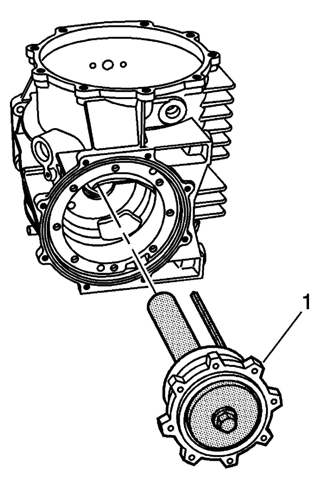
248
249 Fig. 232: Differential Housing & Pinion Housing/Cage Assembly 19. Remove the pinion housing/cage (1) from the differential. Fig. 233: Bearing Races & Components 20. Remove the J , bearings (3 and 6), spacer (5), and J (7) from the pinion housing/cage (4). See Special Tools and Equipment.
 and bearing race (2) to")
250 Fig. 234: Differential, Housing Race & Shim 21. Use the J and a hydraulic press in order to install the selected shims (1) and bearing race (2) to the differential housing. See Special Tools and Equipment.

251 Fig. 235: Differential Case, Differential Housing & J 42155
252 22. Use the J in order to install the differential case into the differential housing. See Special Tools and Equipment.
, and the J 42168-15 (1) onto the differential.")
253 Fig. 236: Right Side Bearing Race, Differential & J Install the right side bearing race (2), and the J (1) onto the differential. See Special Tools and
254 Equipment. Fig. 237: Differential, Cover & Bolts
 and J 42168-16 bolts and spacers to the differential. See Special Tools and Equipment. Position the J 42168-16 bolts and spacers evenly apart.")
255 IMPORTANT: In order to perform the shim selection procedure: The oil seal must be removed from the cover - right. The pinion housing/cage must NOT be installed to the differential case. 24. Install the cover - right (2) and J bolts and spacers to the differential. See Special Tools and Equipment. Position the J bolts and spacers evenly apart. See Special Tools and Equipment. Tighten: Tighten the bolts to 25 N.m (18 lb ft). Fig. 238: Right Side Differential Bearing 25. Insert a feeler gage into the J and measure the gap. See Special Tools and Equipment. The measured dimension is the right side differential bearing shim size.
, cover (2), and tools.")
256 Fig. 239: Differential, Cover & Bolts 26. Remove the bolts (1), cover (2), and tools.
257 Fig. 240: Bearing Race & Shims 27. Install the selected shim (2) and bearing race (1) to the cover - right.
258 Fig. 241: Pressing Shims & Bearing Race Into Cover Using J & Hydraulic Press 28. Install the shim or shims and bearing race into the cover - right using the J and a hydraulic press. See Special Tools and Equipment. Refer to Rear Axle - Assemble. DRIVE PINION ASSEMBLE Tools Required J Pinion Gear Holder. See Special Tools and Equipment. J Bearing and Race Installer. See Special Tools and Equipment. J Bearing Race Installer/Spanner Wrench. See Special Tools and Equipment.
259 Fig. 242: Inner Bearing Race, Pinion Housing/Cage & J IMPORTANT: The spacer is specific for the bearing set and must be used in order to achieve the proper bearing preload. The pinion bearings, spacer and housing/cage must be replaced as a set. 1. Install the inner bearing race into the pinion housing/cage using the J and a hydraulic press, if required. See Special Tools and Equipment.
260 Fig. 243: Outer Bearing Race, Pinion Housing/Cage & J Install the outer bearing race into the pinion housing/cage using the J and a hydraulic press, if required. See Special Tools and Equipment.
261 Fig. 244: Pinion Shaft & J Install the bearing onto the pinion shaft using the J 42170, J 42164, and a hydraulic press. See Special Tools and Equipment.
262 Fig. 245: Nut, Bearing, Spacer & Pinion Shaft & Housing/Cage 4. Assemble the pinion shaft (5), spacer (3), and bearing (2) into the housing/cage (4).
263 Fig. 246: Bearing, Pinion Shaft & J Press the bearing onto the pinion shaft using J 42170, J 42164, and a hydraulic press. See Special Tools and Equipment.
264 7. Using a punch, stake the areas of the nut into the notches in the end of the pinion shaft. 8. Measure the rotating torque of the pinion shaft using the J See Special Tools and Equipment. A properly assembled pinion shaft and bearings should have a rotating torque of N.m (12-25 lb in). Fig. 247: Removing/Installing Pinion Nut Using J NOTE: Refer to Fastener Notice in Cautions and Notices. 6. Install the nut onto the pinion shaft using a torque wrench, J 42172, and J See Special Tools and Equipment. Tighten: Tighten the nut to 500 N.m (370 lb ft).
265 REAR AXLE - ASSEMBLE Tool Required J 8001 Dial Indicator Set. See Special Tools and Equipment. J Output Shaft Seal Installer. See Special Tools and Equipment. J Differential Lifting Tool. See Special Tools and Equipment. J Left Output Shaft Bearing Installer. See Special Tools and Equipment. J Pinion Gear Holder. See Special Tools and Equipment. J Bearing and Race Installer. See Special Tools and Equipment. J Differential Holding Fixture. See Special Tools and Equipment. Fig. 248: Left Side Cover Output Shaft Bearing
266 IMPORTANT: If the pinion assembly components have not been replaced, reuse the original pinion housing shims. If the pinion assembly components have been replaced, refer to Drive Pinion Shim Selection for selection of the proper size shims. 1. Assemble the drive pinion prior to rear axle assembly. Refer to Drive Pinion Assemble. 2. Install the bearing (1) to the cover - left. Fig. 249: Bearing, Left Cover & J Install the bearing into the cover - left using the J and a hydraulic press. See Special Tools and Equipment.
267 Fig. 250: Oil Seal, Left Cover & J Install the oil seal into the cover - left using the J See Special Tools and Equipment.

268 Fig. 251: Oil Seal, Right Cover & J Install the oil seal into the cover - right using the J See Special Tools and Equipment.
269
270 Fig. 252: Pinion Housing/Cage Assembly, Shims & Differential Housing 6. Install the pinion housing assembly (2) and the selected shim or shims (1) to the differential housing. Refer to Drive Pinion Shim Selection for shim selection. The use of M8 x 1.25 dowels or long bolts will ease in pinion housing/cage and shim installation and alignment.
271 Fig. 253: Pinion Housing/Cage Bolts NOTE: Refer to Fastener Notice in Cautions and Notices. 7. Install the pinion housing/cage bolts (1).
272 Tighten: Tighten the bolts to 25 N.m (18 lb ft).
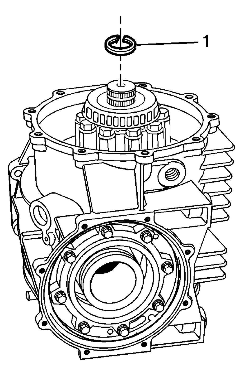
273
274 Fig. 254: Output Shaft & C-Clip 8. Install the C-clip (1) into the groove of the output shaft.
275 Fig. 255: Differential, Transmission Stud Bolts & Mount 9. Apply sealant GM P/N (Canadian P/N ) or equivalent to the threads of the bolts (2)
276 and stud (1). Apply sealant only to the end of the stud that installs into the mount. 10. Install the mount (3) and bolts (2). Tighten: Tighten the bolts to 10 N.m (89 lb in). 11. Install 2 M10 x 1.5 nuts onto the transmission stud (1). Install the stud into the mount. Tighten: Tighten the stud to 42 N.m (31 lb ft).
277 Fig. 256: Differential Cover (Right), Axle Seal & O-Ring Seal 12. Install the O-ring (4) to the groove of the cover - right (3). 13. Install the cover - right and bolts (2). Tighten: Tighten the bolts to 25 N.m (18 lb ft).
278

279 Fig. 257: Transmission Stud & Ring Gear Tooth Surface 14. Install the J 8001 onto the transmission stud. See Special Tools and Equipment. Position the tip of the dial indicator against the center of the ring gear tooth surface. Fig. 258: Splines Of Pinion & J Install the J (1) into the splines of the pinion J will retain the pinion in order to properly measure backlash. See Special Tools and Equipment.
280 Fig. 259: Moving Right Output Shaft In Both Directions 16. Move the output shaft - right in both directions in order to measure the gear backlash. Measure the backlash in two to three locations. Refer to Rear Axle Specifications.
281 Fig. 260: Cover-Rear, Bolts, Bolt/Stud & O-Ring
, bolts (3), bolt/stud (4), and O-ring (1). Tighten: Tighten the bolts and bolt/stud to 10 N.")
282 Fig. 261: J & Differential Assembly IMPORTANT: Note the location of the cover - rear bolt/stud for assembly. 17. Install the cover - rear (2), bolts (3), bolt/stud (4), and O-ring (1). Tighten: Tighten the bolts and bolt/stud to 10 N.m (89 lb in).
283 18. Remove the bolts (3) and the differential assembly (1) from the J (2). See Special Tools and Equipment. Fig. 262: Differential Cover (Left), O-Ring Seal & Bolts 19. Install the O-ring (4) into the groove of the cover - left (3). 20. Install the magnet (5) to the carrier. 21. Apply a continuous 3 mm (0.125 in) bead of sealant GM P/N (Canadian P/N ) or equivalent to the left cover flange (3). 22. Apply sealant around the bolt holes. Keep the sealant away from the O-ring. 23. Install the cover - left (3) and bolts (2). Tighten: Tighten the bolts to 25 N.m (18 lb ft). 24. Clean the excess sealant from the left cover/housing splitline.
284 Fig. 263: Vehicle Speed Sensor & Bolt 25. Install the vehicle speed sensor and bolt. Tighten: Tighten the bolt to 25 N.m (18 lb ft).
 and washer (2).")
285 Fig. 264: Differential, Drain Plug & Washer 26. Install the drain plug (1) and washer (2). Tighten: Tighten the drain plug to 35 N.m (26 lb ft).
, lubricant tag (2), and")
286 Fig. 265: Fill Plug, Lubricant Tag & Washer 27. Install the fill plug (3), lubricant tag (2), and washer (1).

287 Fig. 266: Transaxle Mount Bracket & Differential Bolts 28. Install the transmission mount and bolts. Tighten: Tighten the bolts to 50 N.m (37 lb ft). DESCRIPTION AND OPERATION
288 REAR DRIVE AXLE DESCRIPTION AND OPERATION Getrag Differential Fig. 267: Rear Drive Axle The vehicle is powered by either the LS1 or LS6 5.7 liter V-8 engine, VIN G or S. Motion is transferred from the engine crankshaft/flywheel through the driveline support, propeller shaft, assembly to either the 4L60-E (M30) automatic transmission or the ZF (MM6) 6-speed manual transmission. The splined output shaft of the transmission drives the pinion, which in turn, rotates the ring gear and differential case assembly. The limited slip differential distributes torque/power to the rear wheels via individual axle shaft assemblies. The limited-slip differential is of a conventional separator plate and friction disc type design. The differential housing, side covers, pinion housing, and differential case halves are constructed of cast aluminum. The internal components incorporate a hypoid gear set, ring and pinion, carrier assembly, and pinion housing assembly. The pinion is supported in a pinion housing by tapered roller bearings. The pinion is positioned rearward of the ring gear centerline. Pinion position, ring gear position, and carrier bearing preload are determined by shimming procedures.
289 All models have a 7 5/8 inch ring gear. Each ring gear has specific setup dimensions, A1 and A2 values, stamped onto the side area of the gear. The A1 and A2 values are unique to each ring gear/pinion and are determined during the manufacturers gear/pinion noise and vibration setup and testing. The vehicle speed sensor reluctor ring is incorporated into the outside area of the ring gear. The vehicle speed sensor detects the rotational pulses produced by the reluctor ring and send the signal to the vehicle control module (VCM). The differential assembly is available in three gear ratios. The 3.42 ratio axle is used in all manual transmission applications. The 2.73 ratio axle is standard equipment for automatic transmission applications with an optional 3.15 ratio axle available. SPECIAL TOOLS AND EQUIPMENT SPECIAL TOOLS Special Tools Illustration Tool Number/Description J 8001 Dial Indicator Set J Slide Hammer J Heat Gun
290 J J Bushing and Bearing Remover in J Hydraulic Line Clutch Separator J Transmission Support Fixture
291 Differential Lifting Tool J Left Output Shaft Bearing Installer J Differential Side Bearing Remover J Side Gear Compressor

292 J Pinion Gear Holder J Front Pinion Bearing Remover
2001 Chevrolet CORVETTE
 riveline Support Assembly Replacement (Automatic Transmission) 1 of 21 10/24/2012 8:58 PM 2001 Chevrolet CORVETTE Submodel: Engine Type: V8 Liters: 5.7 Fuel Delivery: FI Fuel: GAS Driveline Support Assembly
DRIVE AXLES. Differentials & Axle Shafts - Corvette
 DESCRIPTION & OPERATION 1998-99 DRIVE AXLES Differentials & Axle Shafts - Corvette A Getrag 625 model differential is used on both the automatic and manual transmissions. Differential carrier and case
MANUAL TRANSMISSIONS. Servicing - Corvette. Transmission Model (RPO Code) Borg-Warner T56 6-Speed (M12)
 Borg-Warner T56 6-Speed (M12)") 2003-04 MANUAL TRANSMISSIONS Servicing - Corvette APPLICATION TRANSMISSION APPLICATION Application Corvette Convertible & Coupe Z06 Transmission Model (RPO Code) Borg-Warner T56 6-Speed (MM6) Borg-Warner
2003-04 MANUAL TRANSMISSIONS Servicing - Corvette APPLICATION TRANSMISSION APPLICATION Application Corvette Convertible & Coupe Z06 Transmission Model (RPO Code) Borg-Warner T56 6-Speed (MM6) Borg-Warner
2007 Hummer H Driveline/Axle Rear Drive Axle - H3. Axle Preload and Backlash Specifications Specification Application
 2007 Driveline/Axle Rear Drive Axle - H3 SPECIFICATIONS AXLE PRELOAD AND BACKLASH SPECIFICATIONS Axle Preload and Backlash Specifications Specification Application Metric English Backlash 0.08-0.25 mm
2007 Hummer H Driveline/Axle Propeller Shaft - H3. Fastener Tightening Specifications Specification Application
 2007 Driveline/Axle Propeller Shaft - H3 SPECIFICATIONS FASTENER TIGHTENING SPECIFICATIONS Fastener Tightening Specifications Specification Application Metric English Bolt - Front Propeller Shaft CV Joint
OVERVIEW: KIT INCLUDES:
 Please visit www.fordracingparts.com for the most current instruction information!!! PLEASE READ ALL OF THE FOLLOWING INSTRUCTIONS CAREFULLY PRIOR TO INSTALLATION. AT ANY TIME YOU DO NOT UNDERSTAND THE
2007 Hummer H Driveline/Axle Wheel Drive Shafts - H3. Fastener Tightening Specifications Specification Application
 2007 Driveline/Axle Wheel Drive Shafts - H3 SPECIFICATIONS FASTENER TIGHTENING SPECIFICATIONS Fastener Tightening Specifications Specification Application Metric English Front Wheel Drive Shaft Nut 260
SUSPENSION 2-1 SUSPENSION TABLE OF CONTENTS
 DN SUSPENSION 2-1 SUSPENSION TABLE OF CONTENTS page ALIGNMENT... 1 FRONT SUSPENSION - 4x2... 6 page FRONT SUSPENSION - 4x4... 14 REAR SUSPENSION... 23 ALIGNMENT TABLE OF CONTENTS page AND OPERATION WHEEL
22-1 GROUP 22 MANUAL TRANSAXLE CONTENTS MANUAL TRANSAXLE... 22A MANUAL TRANSAXLE OVERHAUL... 22B
 22-1 GROUP 22 MANUAL TRANSAXLE CONTENTS............................... 22A OVERHAUL..................... 22B 22A-2 GROUP 22A MANUAL TRANSAXLE CONTENTS GENERAL DESCRIPTION......... 22A-3 DIAGNOSIS 22A-6
Short-throw Shifter Installation Guide
 Short-throw Shifter Installation Guide Removal Procedure 1) Remove the shift control knob. A. Lift up on the rear portion of the shift control closeout boot retaining ring and detach the retaining ring
1 M-3000-H4 F150 4X4 Lowering Kit
 READ INSTRUCTIONS COMPLETELY THROUGH BEFORE STARTING. IT IS RECOMMENDED THAT INSTALLATION BE DONE BY A QUALIFIED MECHANIC. REPLACE ALL STOCK PARTS THAT ARE DAMAGED OR WORN. ALWAYS WEAR EYE PROTECTION.
 Page 1 of 11 2009 Hummer H2 6.2L Eng 1Search Print Date: SHIFT LOCK CONTROL SYSTEM Repair Instructions Automatic Transmission Shift Lock Control Actuator Replacement Removal Procedure NOTE: After assembling
TRANSMISSION AND TRANSFER CASE
 XJ TRANSMISSION AND TRANSFER CASE 21-1 TRANSMISSION AND TRANSFER CASE TABLE OF CONTENTS page AX5 MANUAL TRANSMISSION... 1 NV3550 MANUAL TRANSMISSION... 42 AUTOMATIC TRANSMISSION 30RH... 88 page AW 4 AUTOMATIC
SUSPENSION 2-1 SUSPENSION TABLE OF CONTENTS
 XJ SUSPENSION 2-1 SUSPENSION TABLE OF CONTENTS page ALIGNMENT... 1 FRONT SUSPENSION... 7 page REAR SUSPENSION... 16 ALIGNMENT TABLE OF CONTENTS page AND WHEEL ALIGNMENT...1 DIAGNOSIS AND TESTING SUSPENSION
COMPONENT LOCATOR > DISASSEMBLED VIEWS
 Page 1 of 45 2006 Pontiac Grand Prix 3.8L Eng Base Service Manual: ENGINE MECHANICAL - 3.8L COMPONENT LOCATOR > DISASSEMBLED VIEWS Fig 1: Engine Block Component Views Callout Component Name 100 Engine
SUSPENSION - FRONT Toyota Celica DESCRIPTION ADJUSTMENTS & INSPECTION WHEEL ALIGNMENT SPECIFICATIONS & PROCEDURES WHEEL BEARING
 SUSPENSION - FRONT 1988 Toyota Celica FRONT SUSPENSION Toyota DESCRIPTION Vehicles are equipped with front wheel drive and independent MacPherson strut front suspension. Suspension consists of vertically
REMOVAL & INSTALLATION
 REMOVAL & INSTALLATION AXLE SHAFTS & BEARINGS Removal CAUTION: Failure to turn off air suspension power before raising vehicle may result in unexpected inflation or deflation of air springs. DO NOT reconnect
CLUTCH 6-1 CLUTCH TABLE OF CONTENTS
 PL CLUTCH 6-1 CLUTCH TABLE OF CONTENTS page DESCRIPTION AND OPERATION MODULAR CLUTCH ASSEMBLY....1 CLUTCH CABLE...1 CLUTCH INTERLOCK/UPSTOP SWITCH....1 DIAGNOSIS AND TESTING CLUTCH SYSTEM DIAGNOSIS...2
DIFFERENTIALS & AXLE SHAFTS
 DIFFERENTIALS & AXLE SHAFTS 2001 Chevrolet Camaro 2000-01 DRIVE AXLES General Motors Differentials & Axle Shafts Chevrolet; Camaro Pontiac; Firebird DESCRIPTION & OPERATION Drive axle is a semi-floating,
TRANSMISSION AND TRANSFER CASE
 DR TRANSMISSION AND TRANSFER CASE 21-1 TRANSMISSION AND TRANSFER CASE TABLE OF CONTENTS page MANUAL TRANSMISSION- G56- SERVICE INFORMATION...1 MANUAL TRANSMISSION- GETRAG 238- SERVICEINFORMATION...69 MANUAL
SUSPENSION 2-1 SUSPENSION CONTENTS
 DN SUSPENSION 2-1 SUSPENSION CONTENTS page ALIGNMENT... 1 FRONT SUSPENSION... 5 page REAR SUSPENSION... 13 ALIGNMENT INDEX page GENERAL INFORMATION WHEEL ALIGNMENT... 1 DIAGNOSIS AND TESTING PRE-ALIGNMENT
DIAGNOSIS AND TESTING
 205-02B-1 DIAGNOSIS AND TESTING Rear Drive Axle and Differential Special Tool(s) Dial Indicator Gauge with Holding Fixture 100-002 (TOOL-4201-C) or equivalent 205-02B-1 4 Has the driveline system been
SECTION 5B MANUAL TRANSMISSION TABLE OF CONTENTS
 SECTION 5B MANUAL TRANSMISSION TABLE OF CONTENTS General Description and Operation... 5B-2 Shift Lever... 5B-2 Transmission Assembly... 5B-2 Specifications... 5B-3 Diagnostic Information and Procedures...
The steering column is of a modular construction and features easy to service electrical switches.
 file://c:\tso\tsocache\vdtom_5368\svk~us~en~file=svkb4a01.htm~gen~ref.htm Page 1 of 3 Section 11-04A: Steering Column, Ranger DESCRIPTION AND OPERATION 1997 Ranger Workshop Manual Steering Column NOTE:
REAR DIFFERENTIAL LOCATION INDEX
 2007 DRIVELINE/AXLES Differential - MX-5 Miata REAR DIFFERENTIAL LOCATION INDEX Fig. 1: Identifying Location Of Rear Differential Components DIFFERENTIAL OIL INSPECTION 1. Park the vehicle on level ground
1989 Jeep Cherokee. STEERING COLUMN' '1989 STEERING Jeep Steering Columns STEERING COLUMN STEERING Jeep Steering Columns
 STEERING COLUMN 1989 STEERING Jeep Steering Columns DESCRIPTION All models use collapsible steering columns. All columns have integral ignition switch and locking device. Optional tilt wheel is available
Oil Pan Replacement Buick Regal
 2000 Buick Regal Oil Pan Replacement Removal Procedure Tools Required J 28467-90A Engine Support Adapters J 28467-B Universal Engine Support Fixture J 36462-A Engine Support Adapter Leg Set 1. Disconnect
FRONT AXLE - 9 1/4 AA
 DR FRONT AXLE - 9 1/4 AA 3-45 FRONT AXLE - 9 1/4 AA TABLE OF CONTENTS page FRONT AXLE - 9 1/4 AA DESCRIPTION......................... 45 OPERATION........................... 45 DIAGNOSIS AND TESTING................
'99-03 CHEVROLET/GMC IFS 4WD 6" SUSPENSION SYSTEM P/N INSTALLATION INSTRUCTIONS
 1/16/04 '99-03 CHEVROLET/GMC IFS 4WD 6" SUSPENSION SYSTEM P/N. 10-41099 INSTALLATION INSTRUCTIONS NOTE: Each Lift Kit and options to Lift Kits are packaged separately. Therefore, installation procedures
SECTION 3A FRONT DRIVE AXLE TABLE OF CONTENTS SPECIFICATIONS GENERAL SPECIFICATIONS. Description Drive Shaft Type. CV Joint Axle Housing Type
 SECTION 3A FRONT DRIVE AXLE TABLE OF CONTENTS Specifications........................ 3A-1 General Specifications.................. 3A-1 Fastener Tightening Specifications......... 3A-2 Component Locator...................
A 1 SERVICE SPECIFICATIONS
 A1 A2 Clutch CLUTCH Specifications Pedal height (from asphalt sheet) Release point (from pedal stroke end position) Push rod play at pedal top Pedal freeplay Disc rivet head depth Disc runout Diaphragm
SPECIAL TOOLS Dodge Pickup 5.9L Eng R3500. Fig 1: Identifying Remover C-3985-B (Special Tool) 9/6/13 Printer Friendly View
 9/6/13 Printer Friendly View") Procedures 2003 Dodge Pickup 5.9L Eng R3500 manual transmission SPECIAL TOOLS Fig 1: Identifying Remover C-3985-B (Special Tool) www2.prodemand.com/print/index?content=tabs&module=true&tab=true&terms=true&ymms=false&classname=
Procedures 2003 Dodge Pickup 5.9L Eng R3500 manual transmission SPECIAL TOOLS Fig 1: Identifying Remover C-3985-B (Special Tool) www2.prodemand.com/print/index?content=tabs&module=true&tab=true&terms=true&ymms=false&classname=
DRIVE AXLE - INTEGRAL HOUSING
 DRIVE AXLE - INTEGRAL HOUSING 1993 Toyota Celica 1993 DRIVE AXLES Toyota Differentials & Axle Shafts - Integral Housing Toyota; Celica All-Trac DESCRIPTION Drive axle assembly is a hypoid type with integral
Installation Instructions. QuickSilver Shifter. Fits: GM, Ford, Chrysler Transmissions See Application Guide for Specific Applications Part # 80683
 Installation Instructions QuickSilver Shifter Fits: GM, Ford, Chrysler Transmissions See Application Guide for Specific Applications Part # 80683 WORK SAFELY! For maximum safety, perform this installation
M-5230-V6 Mustang V6 Dual Exhaust Kit INSTRUCTION SHEET
 Please visit www.fordracingparts.com for the most current instruction information.!!! PLEASE READ ALL OF THE FOLLOWING INSTRUCTIONS CAREFULLY PRIOR TO INSTALLATION. AT ANY TIME YOU DO NOT UNDERSTAND THE
2002 F-Super Duty /Excursion Workshop Manual
 Page 1 of 5 SECTION 205-02D: Rear Drive Axle/Differential Ford 10.50-Inch Ring Gear 2002 F-Super Duty 250-550/Excursion Workshop Manual DIAGNOSIS AND TESTING Procedure revision date: 02/02/2005 Rear Drive
M-5230-V6 Mustang V6 Dual Exhaust Kit INSTRUCTION SHEET
 Please contact the Techline for the most current instruction information (800) FORD788.!!! PLEASE READ THE FOLLOWING INSTRUCTIONS CAREFULLY PRIOR TO INSTALLATION!!! OVERVIEW: The use of a floor hoist is
STEERING 19-1 STEERING CONTENTS
 PL STEERING 19-1 STEERING CONTENTS page GENERAL INFORMATION... 1 POWER STEERING PUMP... 9 page STEERING COLUMN... 35 STEERING GEAR... 26 GENERAL INFORMATION INDEX page GENERAL INFORMATION STEERING SYSTEM
1992 Clutch. Eclipse, Expo/Expo LRV, Galant, Mirage, Precis, 3000GT
 Article Text ARTICLE BEGINNING 1992 Clutch Eclipse, Expo/Expo LRV, Galant, Mirage, Precis, 3000GT DESCRIPTION All clutches are single disc type. Pressure plate assembly uses a diaphragm spring to engage
Troubleshooting the Transmission Hydraulic System
 Testing and Adjusting IT28F INTEGRATED TOOLCARRIER POWER TRAIN Testing And Adjusting Introduction Reference: For Specifications with illustrations, refer to SENR5974, IT28F Integrated Toolcarrier Power
MANUAL TRANSAXLE Return to Main Table of Contents
 MANUAL TRANSAXLE Return to Main Table of Contents GENERAL... 2 MANUAL TRANSAXLE CONTROL... 12 SHIFT LEVER ASSEMBLY... 14 MANUAL TRANSAXLE... 15 MANUAL TRANSAXLE ASSEMBLY... 17 FIFTH SPEED SYNCHRONIZER
Parking brake Mechanical brake acting on rear wheels
 11 Brake System 11.1 General SPECIFICATIONS EJTC0010 Master cylinder Type Tandem type I.D. mm(in.) 20.64 mm (0.813 in.) Fluid level warning sensor Provided Brake booster Type Vacuum Boosting ratio 4.0
This file is available for free download at
 This file is available for free download at http://www.iluvmyrx7.com This file is fully text-searchable select Edit and Find and type in what you re looking for. This file is intended more for online viewing
REAR SUSPENSION GROUP CONTENTS GENERAL DESCRIPTION TRAILING ARM REAR SUSPENSION DIAGNOSIS TOE CONTROL ARM...
 34-1 GROUP 34 CONTENTS GENERAL DESCRIPTION 34-2 DIAGNOSIS 34-3 INTRODUCTION TO DIAGNOSIS 34-3 DIAGNOSTIC TROUBLESHOOTING STRATEGY 34-3 SYMPTOM CHART 34-3 SYMPTOM PROCEDURES 34-3 SPECIAL TOOLS 34-5 ON-VEHICLE
BRAKE SYSTEM Nissan 240SX DESCRIPTION BRAKE BLEEDING * PLEASE READ FIRST * BLEEDING PROCEDURES ADJUSTMENTS BRAKE PEDAL HEIGHT SPECS TABLE
 BRAKE SYSTEM 1990 Nissan 240SX 1990 BRAKE SYSTEMS Nissan Disc & Drum Axxess, Maxima, Pathfinder, Pickup, Pulsar NX, Sentra, Stanza, 240SX, 300ZX DESCRIPTION All brake systems are hydraulically operated
REAR SUSPENSION GROUP CONTENTS GENERAL INFORMATION FASTENER TIGHTENING SPECIFICATIONS TRAILING ARM...
 34-1 GROUP 34 CONTENTS GENERAL INFORMATION 34-2 FASTENER TIGHTENING SPECIFICATIONS 34-4 GENERAL SPECIFICATIONS 34-4 SERVICE SPECIFICATIONS 34-5 LUBRICANTS 34-5 DIAGNOSIS 34-6 INTRODUCTION TO DIAGNOSIS
Installation Instructions Z-Gate Shifter
 Installation Instructions Z-Gate Shifter Part Number 80681 1998, 2001 by B&M Racing and Performance Products The B&M Z-Gate shifter can be used in vehicles equipped with most popular three speed automatic
ENGINE REMOVAL & INSTALLATION
 TORQUE VALUES ENGINE MOUNTING = Apply Victory All Purpose Grease 2872187 1. Install all bolts in order A-H Do not tighten. E 41 Nm (30 lb-ft) M8 x 25mm D 111 Nm (82 lb-ft) 12 x 100mm ENGINE INSTALLATION
Return to Instruction Sheet index TCI Installation Instructions for Turbo Hydramatic 350C & 250C
 Page 1 of 6 Return to Instruction Sheet index TCI 326300 Installation Instructions for Turbo Hydramatic 350C & 250C NOTE: This kit was not intended for installation in transmissions that are in poor general
FRONT AXLE GROUP CONTENTS GENERAL DESCRIPTION FRONT AXLE DIAGNOSIS DRIVE SHAFT ASSEMBLY SPECIAL TOOLS...
 26-1 GROUP 26 CONTENTS GENERAL DESCRIPTION 26-2 DIAGNOSIS 26-2 TROUBLESHOOTING STRATEGY 26-2 SYMPTOM CHART 26-3 SYMPTOM PROCEDURES 26-3 SPECIAL TOOLS 26-4 ON-VEHICLE SERVICE 26-6 WHEEL BEARING END PLAY
DRIVE AXLE Volvo 960 DESCRIPTION & OPERATION AXLE IDENTIFICATION DRIVE AXLES Volvo Differentials & Axle Shafts
 DRIVE AXLE 1994 Volvo 960 1994 DRIVE AXLES Volvo Differentials & Axle Shafts 960 DESCRIPTION & OPERATION All 960 station wagon models use type 1041 rear axle assembly. All 960 4-door models use type 1045
COMPONENTS REAR DIFFERENTIAL COMPONENTS
 COMPONENTS REAR DIFFERENTIAL COMPONENTS REMOVAL 1. Drain the differential gear oil. 2. Remove the rear disk brake. 3. Remove the parking brake and cable. 4. Remove the stabilizer bar. 5. Pull out the
REAR AXLE GROUP CONTENTS GENERAL DESCRIPTION DRIVE SHAFT ASSEMBLY REAR AXLE DIAGNOSIS
 27-1 GROUP 27 CONTENTS GENERAL DESCRIPTION 27-2 DIAGNOSIS 27-2 INTRODUCTION 27-2 TROUBLESHOOTING STRATEGY 27-2 SYMPTOM CHART 27-3 SYMPTOM PROCEDURES 27-3 SPECIAL TOOLS 27-8 ON-VEHICLE SERVICE 27-12 TOTAL
BRAKE SYSTEM Return To Main Table of Contents
 BRAKE SYSTEM Return To Main Table of Contents GENERAL... 2 BRAKE PEDAL... 10 MASTER CYLINDER... 13 BRAKE BOOSTER... 16 BRAKE LINE... 18 PROPORTIONING VALVE... 19 FRONT DISC BRAKE... 20 REAR DRUM BRAKE...
SUSPENSION 2-1 SUSPENSION CONTENTS
 ZJ SUSPENSION 2-1 SUSPENSION CONTENTS page ALIGNMENT... 1 FRONT SUSPENSION... 6 page REAR SUSPENSION... 14 ALIGNMENT INDEX page GENERAL INFORMATION WHEEL ALIGNMENT... 1 DIAGNOSIS AND TESTING SUSPENSION
PL TRANSAXLE 21-1 TRANSAXLE TABLE OF CONTENTS NV T350 (A-578) MANUAL TRANSAXLE TH AUTOMATIC TRANSAXLE NV T350 (A-578) MANUAL TRANSAXLE
 MANUAL TRANSAXLE TH AUTOMATIC TRANSAXLE NV T350 (A-578) MANUAL TRANSAXLE") PL TRANSAXLE 21-1 TRANSAXLE TABLE OF CONTENTS page page NV T350 (A-578) MANUAL TRANSAXLE... 1 31TH AUTOMATIC TRANSAXLE... 54 NV T350 (A-578) MANUAL TRANSAXLE TABLE OF CONTENTS page GENERAL INFORMATION
PL TRANSAXLE 21-1 TRANSAXLE TABLE OF CONTENTS page page NV T350 (A-578) MANUAL TRANSAXLE... 1 31TH AUTOMATIC TRANSAXLE... 54 NV T350 (A-578) MANUAL TRANSAXLE TABLE OF CONTENTS page GENERAL INFORMATION
 Page 1 of 7 Section 07-01: Transaxle, Automatic FLC REMOVAL AND INSTALLATION 1992 Tempo/Topaz Workshop Manual Differential In Vehicle Removal Before beginning the Removal procedure, perform the following
PRO RATCHET UNIVERSAL SHIFTER
 Installation Instructions PRO RATCHET UNIVERSAL SHIFTER Fits: GM, Ford and Chryslers w/automatic Transmission See Application Guide for Specific Vehicles Catalog # 80842 WORK SAFELY! For maximum safety,
This file is available for free download at
 This file is available for free download at http://www.iluvmyrx7.com This file is fully text-searchable select Edit and Find and type in what you re looking for. This file is intended more for online viewing
Installation Instructions Sport Shifter
 The B&M Sport Shifter can be used in vehicles equipped with most popular three speed or four speed automatic transmissions. It is equipped with neutral safety and backup light switches, transmission brackets
SISU DP-330 DRIVE GEAR. Maintenance Manual
 SISU DP-330 DRIVE GEAR Maintenance Manual Sisu Axles, Inc. Autotehtaantie 1 PO Box 189 Fin-13101 Hameenlinna Finland Phone +358 204 55 2999 Fax +358 204 55 2900 DP330DG.PDF (3/2007) TABLE OF CONTENTS
1501 Industrial Way N., Toms River, NJ Fax: PACKING LIST MUSTANG LONG TUBE HEADERS (M30000)
") 2/18/04 1501 Industrial Way N., Toms River, NJ 08755 732-349-2109 Fax:732-244-0867 ADVANCED - Installation requires professional-type tools and advanced automotive-service skills. If you lack experience
2/18/04 1501 Industrial Way N., Toms River, NJ 08755 732-349-2109 Fax:732-244-0867 ADVANCED - Installation requires professional-type tools and advanced automotive-service skills. If you lack experience
FRONT AXLE AND SUSPENSION FA 1
 FRONT AXLE AND SUSPENSION FA1 FRONT AXLE AND SUSPENSION FA2 FRONT AXLE AND SUSPENSION Troubleshooting TROUBLESHOOTING Problem Possible cause Remedy Page Wanders/pulls Tires worn or improperly inflated
FRONT AXLE SECTION FAX CONTENTS TRANSMISSION & DRIVELINE FAX-1 SYMPTOM DIAGNOSIS... 2 ON-VEHICLE REPAIR... 7 PRECAUTION... 3
 TRANSMISSION & DRIVELINE SECTION FAX A FRONT AXLE B C FAX CONTENTS E SYMPTOM DIAGNOSIS... 2 NOISE, VIBRATION, AND HARSHNESS (NVH) TROUBLESHOOTING... 2 NVH Troubleshooting Chart...2 PRECAUTION... 3 PRECAUTIONS...
Installation Instructions Right Hand Drive Megashifter
 Installation Instructions Right Hand Drive Megashifter Part Number 80685 1995, 2001, 2006, 2010 by B&M Racing & Performance Products The B&M Right Hand Drive Megashifter is designed specifically for vehicles
2007 Hummer H TRANSMISSION Manual Transmission - Aisin AR5 - H3. Fastener Tightening Specifications Specification Application
 2007 TRANSMISSION Manual Transmission - Aisin AR5 - H3 SPECIFICATIONS FASTENER TIGHTENING SPECIFICATIONS Fastener Tightening Specifications Specification Application Metric English Backup Lamp Switch 44
FRONT AXLE 26-1 CONTENTS GENERAL INFORMATION... 2 HUB AND KNUCKLE ASSEMBLY SERVICE SPECIFICATIONS... 4 DRIVE SHAFT LUBRICANTS...
 26-1 FRONT AXLE CONTENTS GENERAL INFORMATION.................. 2 SERVICE SPECIFICATIONS................. 4 LUBRICANTS.............................. 4 SEALANTS AND ADHESIVES.............. 5 SPECIAL TOOLS...........................
63162K 2015 Chevrolet Colorado 4WD Leveling Kit w/ 1 Rear Lift Kit
 PRO COMP SUSPENSION 63162K 2015 Chevrolet Colorado 4WD Leveling Kit w/ 1 Rear Lift Kit This document contains very important information that includes warranty information and instructions for resolving
EXHAUST SYSTEM AND INTAKE MANIFOLD
 J EXHAUST SYSTEM AND INTAKE MANIFOLD 11-1 EXHAUST SYSTEM AND INTAKE MANIFOLD CONTENTS page EXHAUST SYSTEM... 1 EXHAUST SYSTEM DIAGNOSIS... 2 page SERVICE PROCEDURES... 3 TORQUE SPECIFICATIONS... 10 EXHAUST
MANUAL TRANS OVERHAUL - BORG-WARNER - T56 6-SPEED MANUAL TRANSMISSIONS Borg-Warner T56 (MM6) 6-Speed
 6-Speed") IDENTIFICATION MANUAL TRANS OVERHAUL - BORG-WARNER - T56 6-SPEED 1998 MANUAL TRANSMISSIONS Borg-Warner T56 (MM6) 6-Speed Transmission has 2 identification labels, located on lower left side of case. One
IDENTIFICATION MANUAL TRANS OVERHAUL - BORG-WARNER - T56 6-SPEED 1998 MANUAL TRANSMISSIONS Borg-Warner T56 (MM6) 6-Speed Transmission has 2 identification labels, located on lower left side of case. One
FRONT AXLE SECTION CONTENTS D DRIVELINE/AXLE FAX-1 FAX
 D DRIVELINE/AXLE A SECTION FRONT AXLE B C FAX CONTENTS E PRECAUTIONS... 2 Precautions... 2 PREPARATION... 3 Special Service Tools... 3 Commercial Service Tools... 3 NOISE, VIBRATION, AND HARSHNESS (NVH)
1994 Mazda MX-5 Miata. CLUTCH 1994 Clutch
 CLUTCH 1994 Clutch DESCRIPTION Miata uses a hydraulically operated clutch. HYDRAULIC SYSTEM BLEEDING 1. Remove bleeder screw cap, located at clutch release cylinder. Install vinyl hose onto bleeder screw.
# A: Rear Axle Clunk and/or Chatter Type Noise on Turns (Drain/Refill Rear Differential Fluid) - (Jan 9, 2008)
 - (Jan 9, 2008)") Page 1 of 5 #07-04-20-002A: Rear Axle Clunk and/or Chatter Type Noise on Turns (Drain/Refill Rear Differential Fluid) - (Jan 9, 2008) Subject: Models: Rear Axle Clunk and/or Chatter Type Noise on Turns
Page 1 of 5 #07-04-20-002A: Rear Axle Clunk and/or Chatter Type Noise on Turns (Drain/Refill Rear Differential Fluid) - (Jan 9, 2008) Subject: Models: Rear Axle Clunk and/or Chatter Type Noise on Turns
SECTION 7B3 - MANUAL TRANSMISSION - GEN III V8 ENGINE
 SECTION 7B3 - MANUAL TRANSMISSION - GEN III V8 ENGINE CAUTION: This vehicle will be equipped with a Supplemental Restraint System (SRS). An SRS will consist of either seat belt pre-tensioners and a driver's
1998 Contour/Mystique Workshop Manual
 SECTION 30-01: Automatic Transmission/Transaxle 1998 Contour/Mystique Workshop Manual IN-VEHICLE REPAIR Procedure revision date: 09/14/2001 Main Controls Special Tool(s) Aligner, Selector Shaft 30-S290
1983 BMW 320i. 1.8L 4-CYL 1983 Engines - 1.8L 4-Cylinder Engines - 1.8L 4-Cylinder
 ENGINE IDENTIFICATION 1.8L 4-CYL 1983 Engines - 1.8L 4-Cylinder For engine repair procedures not covered in this article, see ENGINE OVERHAUL PROCEDURES - GENERAL INFORMATION article in the GENERAL INFORMATION
FRONT AXLE SECTION CONTENTS D DRIVELINE/AXLE FAX-1 FAX
 D DRIVELINE/AXLE A SECTION FRONT AXLE B C FAX CONTENTS E PRECAUTIONS... 2 Precautions... 2 PREPARATION... 3 Special Service Tools... 3 Commercial Service Tools... 3 NOISE, VIBRATION, AND HARSHNESS (NVH)
Inspection and Verification, Ranger
 file://c:\tso\tsocache\vdtom_5368\svk~us~en~file=svk53a03.htm~gen~ref.htm Page 1 of 1 Section 05-03A: Wheel Hubs and Bearings, Front Wheels, 4- Wheel Drive DIAGNOSIS AND TESTING 1997 Ranger 4x4 with Dana
FRONT AXLE GROUP CONTENTS DRIVE SHAFT ASSEMBLY GENERAL DESCRIPTION FRONT AXLE DIAGNOSIS SPECIAL TOOLS...
 26-1 GROUP 26 CONTENTS GENERAL DESCRIPTION 26-2 DIAGNOSIS 26-3 TROUBLESHOOTING STRATEGY 26-3 SYMPTOM CHART 26-3 SYMPTOM PROCEDURES 26-4 SPECIAL TOOLS 26-5 ON-VEHICLE SERVICE 26-8 WHEEL BEARING END PLAY
1 Green Pressure Regulator Spring Automatic transmissions operate at temperatures between 150ºF and
 Installation Instructions for 603107 Valve Body Kit C-4 1970 & Later Tools Required Speed Handle or Ratchet 3/8 Drive 1/2 Socket 3/8 Drive 7/16 Socket 3/8 Drive 5/16 Socket 3/8 Drive Small Screwdriver
M Ring and Pinion Installation
 !!! PLEASE READ ALL OF THE FOLLOWING INSTRUCTIONS CAREFULLY PRIOR TO INSTALLATION. Axle Shaft Removal (1994-2012 Mustang typical) STEP 1: STEP 2: Remove the 10 differential housing cover bolts and drain
CLUTCH Toyota Celica DESCRIPTION ADJUSTMENTS CLUTCH PEDAL HEIGHT Clutch. Celica
 CLUTCH 1993 Toyota Celica 1993 Clutch Celica DESCRIPTION The single, dry disc type clutch uses a hydraulically operated master cylinder and a release cylinder mounted on clutch housing. Clutch release
REAR AXLE AND SUSPENSION RA 1
 REAR AXLE AND SUSPENSION RA1 RA2 REAR AXLE AND SUSPENSION Troubleshooting TROUBLESHOOTING Problem Possible cause Remedy Page Wanders/pulls Tires worn or improperly inflated Replace tires or inflate to
1501 Industrial Way N., Toms River, NJ Fax: PACKING LIST MUSTANG GT LONG TUBE HEADERS (M30000)
") ADVANCED - Installation requires professional-type tools and advanced automotive-service skills. If you lack experience with internal engine modifications, an Advanced installation is probably beyond your
ADVANCED - Installation requires professional-type tools and advanced automotive-service skills. If you lack experience with internal engine modifications, an Advanced installation is probably beyond your
FRONT AXLE GROUP CONTENTS ON-VEHICLE SERVICE GENERAL INFORMATION GENERAL SPECIFICATIONS SERVICE SPECIFICATIONS...
 26-1 GROUP 26 CONTENTS GENERAL INFORMATION 26-2 GENERAL SPECIFICATIONS 26-3 SERVICE SPECIFICATIONS 26-4 LUBRICANTS 26-4 DIAGNOSIS 26-4 TROUBLESHOOTING STRATEGY 26-4 SYMPTOM CHART 26-4 SYMPTOM PROCEDURES
TROUBLESHOOTING SPECIAL TOOL ASSEMBLY AND ADJUSTMENT
 1 INDEX Models FD, FE, FF and SG REAR AXLE 10-1 10-108E-07 CHAPTER 10 REAR AXLE Models FD, FE, FF and SG TROUBLESHOOTING...10-2 10 SPECIAL TOOL...10-3 WHEEL HUB AND RELATED PARTS DISASSEMBLY...10-7 INSPECTION...10-9
TSM54/52 MANUAL TRANSMISSION
 3B-1 SECTION 00 3B TSM54/52 MANUAL TRANSMISSION Table of Contents GENERAL INFORMATION... 3B-3 Overview... 3B-3 Specifications... 3B-4 System components... 3B-5 Shifting mechanism... 3B-17 Diagnostic information
SUSPENSION AND AXLE SA 1 SUSPENSION AND AXLE
 SA1 SA2 Troubleshooting TROUBLESHOOTING Problem Possible cause Remedy Front Page Rear Wanders/pulls Tires worn or improperly inflated Wheel alignment incorrect Hub bearing worn Front or rear suspension
CLUTCH 6-1 CLUTCH CONTENTS
 TJ CLUTCH 6-1 CLUTCH CONTENTS page GENERAL INFORMATION CLUTCH COMPONENTS... 1 INSTALLATION METHODS AND PARTS USAGE... 1 DESCRIPTION AND OPERATION CLUTCH OPERATION... 1 DIAGNOSIS AND TESTING DIAGNOSTIC
Engine. Special Tool(s) Compressor, Piston Ring 303-D032 (D81L-6002-C) or equivalent. Compressor, Valve Spring (T93P-6565-AR)
 Compressor, Piston Ring 303-D032 (D81L-6002-C) or equivalent. Compressor, Valve Spring (T93P-6565-AR)") SECTION 303-01C: Engine 5.4L (4V) 2009 Mustang Workshop Manual ASSEMBLY Procedure revision date: 12/12/2008 Engine Special Tool(s) Compressor, Piston Ring 303-D032 (D81L-6002-C) or equivalent Compressor,
SECTION 303-01C: Engine 5.4L (4V) 2009 Mustang Workshop Manual ASSEMBLY Procedure revision date: 12/12/2008 Engine Special Tool(s) Compressor, Piston Ring 303-D032 (D81L-6002-C) or equivalent Compressor,
INSTALLATION INSTRUCTIONS
 INSTALLATION INSTRUCTIONS PERFORMANCE AT THE WHEELS KIT W125-42 GM 10 & 12 Bolt Rear Axles with Staggered or non-staggered Shocks with C-Clips Thank you for choosing STAINLESS STEEL BRAKES CORPORATION
FRONT AXLE SECTION CONTENTS D DRIVELINE/AXLE FAX-1 FAX
 D DRIVELINE/AXLE A SECTION FRONT AXLE B C FAX CONTENTS E PRECAUTIONS... 2 Precautions for Supplemental Restraint System (SRS) AIR BAG and SEAT BELT PRE-TEN- SIONER... 2 Precautions... 2 PREPARATION...
Diagnostic Procedures
 Section 6 Diagnostic Procedures Learning Objectives: 1. Describe manual transmission, transaxle and transfer case component inspection and diagnostic procedures 2. Identify clutch component inspection
TRANSMISSION INSTALLATION CONTENTS
 A REGAL-BELOIT Company TRANSMISSION INSTALLATION CONTENTS RICHMOND 6-SPEED TRANS AM, CAMARO, CHEVELLE, GTO, CUTLASS, WITH T-10/MUNCIE............2 RICHMOND 6-SPEED 1963 TO 1982 CORVETTE WITH T-10 OR MUNCIE..............................3
Installation Instructions Megashifter
 Installation Instructions Megashifter The B&M Megashifter shifter can be used in vehicles equipped with most popular three speed or four speed automatic transmissions. Your B&M Megashifter comes equipped
Hurst VMATIC3 INSTALLATION
 FORM 159 8530 07/12 Hurst VMATIC3 3-Speed & 4-Speed Automatic Shifter Catalog #3838530 2012 by Hurst Performance The Hurst Vmatic3 shifter can be used in vehicles equipped with most popular three speed
2012 MKT Workshop Manual. REMOVAL AND INSTALLATION Procedure revision date: 06/13/2011
 SECTION 205-05: Rear Drive Halfshafts REMOVAL AND INSTALLATION Procedure revision date: 06/13/2011 Halfshaft Special Tool(s) Axle Seal Protector 205-816 Front Hub Remover 205-D070 (D93P-1175-B) or equivalent
DRIVE SHAFT & FRONT AXLE
 DRIVE SHAFT & FRONT AXLE Return To Main Table of Contents GENERAL... 2 DRIVE SHAFT... 6 HUB AND KNUCKLE... 13 FRONT AXLE... 15 GENERAL GENERAL SPECIFICATIONS Drive shaft Joint type Outer Inner Length (Joint
FRONT AXLE Click on the applicable bookmark to selected the required model year
 FRONT AXLE 26-1 FRONT AXLE CONTENTS GENERAL INFORMATION.................. 2 SERVICE SPECIFICATIONS................. 4 LUBRICANTS.............................. 4 SEALANTS AND ADHESIVES.............. 5 SPECIAL
FRONT AXLE SECTION FAX CONTENTS D DRIVELINE/AXLE FAX-1 FAX
 FRONT AXLE D DRIVELINE/AXLE SECTION FAX A FRONT AXLE B C FAX CONTENTS E PRECAUTIONS... 2 Caution... 2 PREPARATION... 3 Special Service Tools (SST)... 3 Commercial Service Tools... 5 NOISE, VIBRATION AND