McCONNEL ROBOCUT REMOTE CONTROLLED MOWER. Operator & Parts Manual. Publication 679 August 2011 Part No Revision:
|
|
|
- Blaise O’Brien’
- 5 years ago
- Views:
Transcription


1 Publication 679 August 2011 Part No Revision: ROBOCUT REMOTE CONTROLLED MOWER Operator & Parts Manual
2 IMPORTANT VERIFICATION OF WARRANTY REGISTRATION DEALER WARRANTY INFORMATION & REGISTRATION VERIFICATION It is imperative that the selling dealer registers this machine with McConnel Limited before delivery to the end user failure to do so may affect the validity of the machine warranty. To register machines go to the McConnel Limited web site at log onto Dealer Inside and select the Machine Registration button which can be found in the Service Section of the site. Confirm to the customer that the machine has been registered in the section below. Should you experience any problems registering a machine in this manner please contact the McConnel Service Department on Registration Verification Dealer Name:... Dealer Address:.. Customer Name:.. Date of Warranty Registration: / /... Dealer Signature:.. NOTE TO CUSTOMER / OWNER Please ensure that the above section above has been completed and signed by the selling dealer to verify that your machine has been registered with McConnel Limited. IMPORTANT: During the initial bedding in period of a new machine it is the customer s responsibility to regularly inspect all nuts, bolts and hose connections for tightness and re-tighten if required. New hydraulic connections occasionally weep small amounts of oil as the seals and joints settle in where this occurs it can be cured by re-tightening the connection refer to torque settings chart below. The tasks stated above should be performed on an hourly basis during the first day of work and at least daily thereafter as part of the machines general maintenance procedure. CAUTION: DO NOT OVER TORQUE HYDRAULIC FITTINGS AND HOSES TORQUE SETTINGS FOR HYDRAULIC FITTINGS HYDRAULIC HOSE ENDS PORT ADAPTORS WITH BONDED SEALS BSP Setting Metric BSP Setting Metric 1/4 18 Nm 19 mm 1/4 34 Nm 19 mm 3/8 31 Nm 22 mm 3/8 47 Nm 22 mm 1/2 49 Nm 27 mm 1/2 102 Nm 27 mm 5/8 60 Nm 30 mm 5/8 122 Nm 30 mm 3/4 80 Nm 32 mm 3/4 149 Nm 32 mm Nm 41 mm Nm 41 mm 1.1/4 190 Nm 50 mm 1.1/4 305 Nm 50 mm 1.1/2 250 Nm 55 mm 1.1/2 305 Nm 55 mm Nm 70 mm Nm 70 mm
3 WARRANTY POLICY WARRANTY REGISTRATION All machines must be registered, by the selling dealer with McConnel Ltd, before delivery to the end user. On receipt of the goods it is the buyer s re sponsibility to check that the Verification of Warranty Registration in the Operator s Manual has been completed by the selling dealer. 1. LIMITED WARRANTIES All machines supplied by McConnel Limited are warranted to be free from defects in material and workmanship from the date of sal e to the original purchaser for a period of 1 2 months, unless a different period is specified All spare parts supplied by McConnel Limited are warranted to be free from defects in material and workmanship from the date of sale to the original purchaser for a period of 6 months The manufacturer will replace or rep air for the p urchaser any part or pa rts found, upon examination at its factory, to be defective under normal use a nd service due to defects in material or workmanship. Returned parts must be complete and unexamined This warranty does not apply to any part of the goods, which has been subjected to improper or abnormal use, negligence, alteration, modification, fitment of non-genuine parts, accid ent damage, or damage resulting from contact with overhead power lines, dam age caused by foreign objects (e.g. stones, iron, ma terial other than vegetati on), failure due to lack of maintenance, use of incorrect oil or lubricants, contamination of the oil, or which has served its normal life. This warranty does not ap ply to any expendable items such as blades, flails, flap kits, skids, soil engaging parts, shields, guards, wear pads or pneumatic tyres Temporary repairs an d consequential loss - i.e. oil, do wntime and associated parts are specifically excluded from the warranty Warranty on hoses is limit ed to 12 months and does not include hoses w hich have suffere d external damage. Only complete hoses may be returned under warranty, any which have been cut or repaired will be rejected Machines must be repaired immediately a problem arises. Continued use of the machine after a problem has occurred can result in furt her component failures, for which McConnel Ltd ca nnot be held liable, and may have safety implications Except as provided herein, no employee, agent, dealer or other person is authorised to give any warranties of any nature on behalf of McConnel Ltd For machine warranty periods in excess of 12 months the follo wing additional exclusions shall apply: 1) Hoses, external seals, exposed pipes and hydraulic tank breathers. 2) Filters. 3) Rubber mountings. 4) External electric wiring All service work, particularly filter c hanges, must be carried out in accordance with the manufacturer s service schedule. Failure to comply will invalidate the warranty. In the event of a claim, proof of the service work being carried out may be required. NB Warranty cover will be invalid if any non-genuine parts have been fitted or used. Use of non-genuine parts may seriously affect the machine s performance and safety. McConnel Ltd cannot be held responsible for any failures or safety implications that arise due to the use of non-genuine parts.
4 2. REMEDIES AND PROCEDURES The warranty is not effective unless the Selling Dealer registers the machine, via the McConnel web site and confirms the registration to the purchaser by completing the confirmation form in the operator s manual Any fault must be reported to an authorised McConnel dealer as soon as it o ccurs. Continued use of a m achine, after a f ault has occurred, can result in further component failure for which McConnel Ltd cannot be held liable Repairs should be undertaken within two days of the failure. Claims submitted for re pairs undertaken more than 2 weeks after a failure ha s occurred, or 2 days after the pa rts were supplied will be rejected, unless the delay has been authorised by McConnel Ltd All claims must be submitted, by an aut horised McConnel Service Dealer, within 30 days of the date of repair Following examination of the claim an d parts the manufacture will pay, at their discretio n, for any valid claim the cost of any parts and an appropriate labour allowance if applicable The submission of a claim is not a guarantee of payment Any decision reached by McConnel Ltd. is final. 3. LIMITATION OF LIABILITY The manufacturer disclaims any express (exc ept as set forth herein) an d implied warranties with respect to the goods including, but not limited to, merchantability and fitness for a particular purpose The manufacturer makes no warranty as to the design, capability, capacity or suitability for use of the goods Except as provi ded herein, the m anufacturer shall have no liability or responsibility to the purchaser or any other person or entity with respect to any liability, loss, or damage caused o r alleged to be caused directly or indirectly by the goods including, but not limited to, any indirect, special, consequential, or incidental damages resulting from the use or operation of the goods or any breach of this warranty. Notwithstanding the above limitations and warranties, the manufacturer s liability hereund er for d amages incurred by the purchase r or others shall not exceed the price of the goods No action arising out of any claimed breach of this warranty or transactions under this warranty may be brought more than one (1) year after the cause of the action has occurred. 4. MISCELLANEOUS The manufacturer may waive compliance with any of the terms of this limited warranty, but no waiver of any terms shall be deemed to be a waiver of any other term If any provision of this limited warranty shall violate any applic able law and is held to be unenforceable, then the invalidity of such provision shall not invalidate any other provisions herein Applicable law may provide rights an d benefits to the purchaser in addition to those provided herein.

 Safety of machinery - Risk assessment, Part 1: Principles Part 2: practical guide and examples of methods.")
5 DECLARATION OF CONFORMITY Conforming to EU Machinery Directive 2006/42/EC We, LIMITED, Temeside Works, Ludlow, Shropshire SY8 1JL, UK Hereby declare that: The Product; Radio Controlled Tracked Mower Product Code; RMOW Serial No. & Date Type Manufactured in; Italy Complies with the required provisions of the Machinery Directive 2006/42/EC The machinery directive is supported by the following harmonized standards; BS EN ISO (2007) Safety of machinery - Risk assessment, Part 1: Principles Part 2: practical guide and examples of methods. BS EN ISO (2010) Safety of mach inery - Part 1: Basic terminology and methodology Part 2: Technical principles. BS EN 349(1993)+ A1 (2008) Safety of machinery - Minimum distances to avoid the entrapment with human body parts. BS EN 953 (1998) Safety of machinery - Guards General requirements for the design and construction of fixed and movable guards. BS EN 982(1996)+ A1 (2008) Safety requirements for fluid power systems and their components. Hydraulics LIMITED operates an IS O 9001:2008 quality management system, certificate number: FM This system is continually assessed by the; British Standards Institution (BSI), Beech House, Milton Keynes, MK14 6ES, UK BSI is accredited by UK Accreditation Service, accreditation number: UKAS 003. The EC declaration only applies if the machine stated above is used in accordance with the operating instructions. Signed... Responsible Person CHRISTIAN DAVIES on behalf of LIMITED Status: General Manager Date: May 2011
6 LIST OF CONTENTS Page No. Operator Section General Information 1 Features & Specifications 2 Safety Information 3 Safety Decals & Warnings 6 Safety Devices & Emergency Stop 7 Machine Delivery 8 Machine Overview 9 Starting the Engine 14 Driving & Manoeuvring 15 Emergency Manual Control Unit 20 Pre-Operation Checks 22 Operation 23 Maintenance 25 Undercarriage Specifications 37 Electrical System Fuses & Relays 38 Troubleshooting 39 Parts Section Chassis Assembly 42 Rubber Tracks 44 Equipment Mounting Assembly 46 Engine Cover Assembly 48 Machine Cover Assembly 50 Diesel Engine Assembly 52 Diesel Engine Components 56 Pumps Assembly 58 Actuator Assembly 60 Reversible Fan System 62 Diesel Fuel Circuit 64 Oil Tank Assembly 66 Electrical Components 68 Electrical Wiring 72 Control Transmitting / Receiving Units Robocut Models 74 Control Transmitting / Receiving Units Robocut PURE Models 76 Intake & Drain Pumps 78 Change Over Valve Circuit 82 Tracks Hydraulic Circuit 84 Hydraulic Rams Circuit 88 Hydraulic Equipment Circuit 90 Flailhead Assembly 92 Rotors & Flails 96 Decal Kit 98 Service Parts 99
7
8 GENERAL INFORMATION Always read this manual before attempting to operate the machine whenever any doubt exists contact your dealer or the McConnel Service Department for advice and assistance. Use only McConnel Genuine Service Parts on McConnel Equipment and Machines DEFINITIONS The following definitions apply throughout this manual: WARNING An operating procedure, technique etc., which can result in personal injury or loss of life if not observed carefully. CAUTION An operating procedure, technique etc., which can result in damage to either machine or equipment if not observed carefully. NOTE An operating procedure, technique etc., which is considered essential to emphasis. LEFT AND RIGHT HAND These terms are applicable to the machine when it is viewed from the rear facing forwards. Note: The illustrations in this manual are for instructional purposes only and may on occasion not show some components in their entirety. In some instances an illustration may appear slightly different to that of your particular model but the general procedure will be the same. E&OA. MACHINE & DEALER INFORMATION Record the Serial Number of your machine on this page and always quote this number when ordering parts. Whenever information concerning the machine is requested remember also to state the make and model of tractor to which the machine is fitted. Machine Serial Number: Machine Model details: Dealer Name: Dealer Address: Dealer Telephone No: Dealer Address: Installation Date: 1
9 FEATURES & SPECIFICATIONS RoboCut 40HP (29kW) 3 Cylinder ISUZU Diesel Engine Tracked Carriage Hydraulically Driven via Piston Pumps Self-Tightening Tracks Remote Controlled Operation (up to 150m range) Rubber Tracks with Removable Riveted Stirrups Rubber Stopper Spike Protection for Transport Potentiometer Speed Control from 0 to 100% Independent Cooling System for Hydraulic Circuits Self-Cleaning Reversible Fan Electronically Controlled, Hydraulically Powered Flail Head Proportional Joystick Speed Control Forwards & Backwards 0 to 7km/h 21 Litre Fuel Tank Capacity 1280mm Carriage Width 1.3m Flail Head capable of cutting materials up to 30mm diameter Machine Weight 1000kg 2

10 SAFETY INFORMATION This machine has the potential to be extremely dangerous - in the wrong hands it can kill or maim; It is therefore imperative that both owner and operator of the machine reads and understands the following section to ensure they are fully aware of the dangers that do, or may exist, and their responsibilities surrounding the use and operation of the machine. The operator of this machine is responsible not only for their own safety but equally for the safety of others who may come into the close proximity of the machine, as the owner you are responsible for both. When the machine is not in use it should be parked on a firm level site with the cutting head resting on the ground and the starting key removed. In the event of any fault being detected with the machine s operation it must be stopped immediately and not used again until the fault has been corrected by a qualified technician. Before starting the machine the operator must read and understand all aspects of use and maintenance of the machine as stated in this manual. The machine must only be used by a responsible adult who is familiar with all aspects relating to safe operation. The machine must not be operated by children or non-authorised persons. Operators must know the meaning of all operation and safety decals on both the machine and the remote control unit. Operators must know the procedure for switching the machine off normally and by using the Emergency Stop. Do not attempt to use the machine if the Emergency Stop switch is damaged or malfunctioning. Never use the machine with safety guarding removed or defective. 3
11 Operators should practice operation on flat open ground to familiarise themselves with driving and manoeuvring the machine before attempting to use it on sloping ground. Operators should practice manoeuvring the machine around obstacles without the flail head running before using the machine for work purposes. Never operate the machine when your vision is blocked by obstacles such as vehicles, buildings, hedges etc.; move to a position where you have an un-interrupted view of the machine. Never operate the machine standing directly in the line of travel. Do not use the machine on sand piles, gravel, or similar materials. Only operate the machine in good light conditions. Never run the machine in an enclosed area or building. Keep the machine clean to avoid build ups of dry materials that could ignite on hot components. Never stand directly below a machine that is operating or parked on a slope. Always operate the joystick control slowly; rapid or jerky movements can cause the machine to rear up causing loss of control. When operating the machine with the flail head running the operator must remain at least 5 metres away from the machine; always switch the flail head off before approaching it. When using the machine the operator should place themselves in a position that provides optimum visibility over the work area. Never leave a running machine unattended; always switch the engine off and remove the ignition key. Always stop and switch the machine off if persons or animals enter the work area, do not restart the machine until they are at a safe distance. Never use the machine to perform tasks it was not designed for. Never ride, or allow others to ride on the machine. Always inspect the work area prior to operation and remove stones, glass, metal, wire or any other foreign objects that are hazardous. Immovable hazards should be marked so they can be avoided. Take extra care when operating the machine on slopes or uneven ground, there is increased risk of objects being thrown from the flail head when working in these conditions. The machine can be used on slopes of up to 50 (maximum) providing the surface is dry and firm. 4
12 Should a machine overturn, a suitable crane or winch should be used to recover it, keep all persons at a safe distance before and during recovery. Do not operate the machine in foggy or frosty conditions as there is increased risk of accidents. Take extra care when working in close proximity to electrical cables; in some circumstances, operating the machine under overhead power lines can result in loss of radio signal causing the engine to deactivate. Do not operate the machine close to vehicles or properties where there is risk of damage by objects accidentally thrown from the flail head. It is the user s responsibility to protect persons in or near the work zone. When servicing or maintaining the machine no one should be allowed beneath it when it is raised unless it is securely supported on suitable ramps or stands. Never attempt to service or maintain the machine whilst it is running; always switch off the engine and remove the starting key. When transporting the machine on another vehicle or trailer the engine must be switched off and the machine chocked and secured using suitable ropes or chains. Check the condition of the flails and fixings on a regular basis; never use the machine with damaged/missing flails or loose fixings. Always clean the machine after use; care must be taken if the machine is hot. Never use solvent based chemicals for cleaning. When operating in excessively dusty conditions work may need to be interrupted on a regular basis to remove any build ups of dust on components that could cause overheating. Always press the Emergency Stop switch before refuelling. Wherever possible refuel the machine before work when the engine is cold. If refuelling during work, switch off the engine and allow it to cool before adding fuel. Test the Emergency Stop switch before each period of work to ensure it functions correctly. Never leave the machine, ignition key and control unit unattended where it could be started and used by un-authorised persons. Any inspection, service or maintenance of the flail head must only be performed with machine switched off and the starting key removed. Always wear safety gloves and glasses when performing service or maintenance on the flail head. Flail head must always be switched off when manoeuvring outside of the work zone. 5

13 SAFETY & WARNING DECALS 1. WARNING: Read the manual first. 2. DANGER: Risk of thrown objects, keep your distance. 3. DANGER: Electrical voltage and harmful substances. 4. DANGER: Acid, read the user and maintenance manual. 5. DANGER: Rotating components, keep clear. 6. DANGER: Hot components, risk of burns. 7. WARNING: Do not lubricate or service moving components, stop the machine first. 8. ADVISORY: Always wear ear defenders and safety glasses when using the machine. 9. ADVISORY: Always wear safety footwear when using the machine. 6
14 SAFETY DEVICES & EMERGENCY STOP Automatic Emergency Safety Features As the RoboCut is operated by remote control and the user is not directly operating the driving elements of the machine specific safety features have been built in to protect the user, third party persons and the machine itself; these are as follows Danger / Risk Situation Machine beyond signal reception area or radio signal blocked. Radio signal failure. Another machine on same frequency operating in the area. Automatic Safety Feature EMERGENCY STOP will activate. EMERGENCY STOP will activate. EMERGENCY STOP will activate. Manual Emergency Safety Feature In addition to the automatic safety features stated above the operator can immediately stop the machine either by pressing the Emergency Stop button located on the remote control unit or by pressing the Emergency Stop button located on the top panel of the machine itself. In all instances stated above, emergency stopping of the machine will take a maximum of 0.2 seconds from execution of the automatic or manual command and the following actions will occur; Engine will be switched off Ignition will be turned off. Machine movement will be halted. Electrical voltage will be deactivated. Entire electrical system will be disabled. In the unlikely event of movement malfunction If machine movements perform in an unexpected or incorrect manner follow the instructions below; 1) Release the forwards/backwards movement joystick the control is equipped with automatic zero position; on release it will automatically return to the central (stop) position, this action activates the track brakes. 2) Press the Emergency Stop button on the control unit. DANGER! Do not approach the machine if it is moving. 3) Press the machine s Emergency Stop button. 4) Turn the ignition key into the off position (anti-clockwise) and remove the key. Contact your Authorised Dealer or McConnel Service do not attempt to operate the machine until advice has been sought. 7

15 MACHINE DELIVERY The machine will be delivered ready for use having been pre-filled with all necessary lubricants and fluids other than fuel. Before use all packaging must be removed and the transport fasteners loosened. The reception antenna will be supplied as a loose item and must be screwed onto the machines receiver prior to use. The standard items supplied will be as follows: Standard Equipment Machine with Mounted Receiver Transmitter and Battery Pack Reserve Battery Pack Battery Charger 12V CA Antenna Belt for the Radio Control Ignition Key Use and Maintenance Manual for Machine Use and Maintenance Manual for Transmitter Use and Maintenance Manual for Engine Machine Lifting Points The photos below shown the machine s lifting points; the lifting eyes are located at each end of the track plates on both sides of the machine. The positions of the lifting points enable the machine to be safely raised using suitable overhead lifting equipment. Note: All equipment used to raise the machine must have a SWL in excess of the total weight of the machine keep all persons at a safe distance from the machine during the lifting procedure. 8
 Left Side View 1.")


16 MACHINE OVERVIEW Component Identification Right Side View 1. Oil Tank 2. Diesel Fuel Tank 3. Track Tensioner Access 4. Track Roller 5. Drive Wheel 6. Alternator (12V) Left Side View 1. Hydraulic Motor 2. Electrics 3. Warning Beacon Mount 4. Water / Oil Radiator 5. Conveyor & Radiator Guard 6. Rubber Tracks 7. Electric Actuator 8. Track Tensioner Access 9. Lubrication Point 10. Hydraulic Ram (Front Hood) Engine Top View 1. Air Filter Clogging Sensor 2. Radio Control Antenna 3. Warning Beacon Mount 4. Engine Oil Filler Plug 5. Air Filter 6. Air Filter Breather 9
 6. Horn 7. Electric Compressor (Self-Cleaning Radiator Fan) 8. Ant-vibration Engine Support 9. Exhaust Pipe 10.")

17 Engine Right Side View 1. Radiator Filler 2. Radio Control Antenna 3. Warning Beacon Mount 4. Emergency Stop Switch 5. Electric Plug for Services (12V) 6. Horn 7. Electric Compressor (Self-Cleaning Radiator Fan) 8. Ant-vibration Engine Support 9. Exhaust Pipe 10. Alternator (12V) 11. Air Filter Engine Left Side View 1. Emergency Stop Switch 2. Warning Beacon Mount 3. Air Filter 4. Radiator Fan Guard 5. Radiator Filler 6. Oil Cooler Input 7. Oil Cooler Output 8. Engine Oil Filler Plug 9. Secondary Fuel Filter 10. Electric Actuator 11. Electric Pump 12. Temperature Gauge (Engine Coolant) 13. Ignition Key 10
 3. Hours Counter (Engine Running Time) 4.")
18 Ignition Panel Components 1. Temperature Gauge (Engine Coolant) 2. LED Lights 1-10 (see symbols below) 3. Hours Counter (Engine Running Time) 4. Ignition Switch Ignition Panel Warning Symbols 11
19 Ignition Panel Warnings WARNING SYMBOL LED LIGHT REFERENCE AUDIBLE WARNING CAUSE REMEDY 1. Yellow LED Light Yes Fuel tank running on reserve. Top up fuel. 2. Red LED Light No Parking brake on. 3. LED Light Yes Hydraulic oil level too low. Check brake release valve pressure. Check for leaks and repair. Replenish hydraulic oil. 4. Red LED Light No Alternator not charging battery. Contact local dealer. 5. Yellow LED Light No Air filter blocked. Disassemble the filter cartridge and clean with compressed air line. 6. Red LED Light Yes Oil filter blocked Replace oil filter cartridge. 7. Yellow LED Light No Pre-heat plugs are on. 8. Red LED Light & 9. Red LED Light Yes Insufficient engine oil pressure. Wait for light to go out before attempting to start engine. Replenish oil if required. If oil level correct seek advice from local dealer. 9. Red LED Light No Engine stop Reset Emergency Switch. 10. Red LED Light Yes Coolant temperature too high. Check coolant level. Clean radiator matrix and protection guard. 12
 8. Emergency Stop Switch 9. Rotor Direction Selector 10. Gear Selector 11. Direction Swap 12. Fan Reverse Control (Radiator Self-Clean) 13.")
20 Radio Control Unit Control Locations & Functions 1. Display 2. Potentiometer Speed Regulator 3. Right Joystick Steering (Left / Right) O Flail Head (Up / Down) 4. Auxiliary #1 5. Auxiliary #2 6. Front Hood 7. Flail Head Pump Control (Rotor Speed) 8. Emergency Stop Switch 9. Rotor Direction Selector 10. Gear Selector 11. Direction Swap 12. Fan Reverse Control (Radiator Self-Clean) 13. Left Joystick Drive (Forward) O Default O Drive Swap Mode Drive (Reverse) switch 11 activated 14. Steering Bios 15. Engine Start 16. Horn 17. Codified Key 18. Engine Stop 19. Engine Revs (-) 20. Battery 21. Engine Revs (+) 13
21 STARTING THE ENGINE Before attempting to start the engine ensure you have read and understood the manual and observe all safety instructions surrounding use of the engine and machine. WARNING! Engine must only be started in open air, never in an enclosed environment. Diesel Engine Starting Observe all Safety Instructions. Ensure machine is in the open air and not in an enclosed environment. Check fuel level and replenish if required. Turn ignition key on the machine clockwise to the first position; pre-heat plug light on the ignition panel will illuminate wait until light goes out before continuing. NOTE: When the ignition key is turned to the first position the machine will perform a sequence of system checks during which time lights on the control panel will be lit or flashing, when the check is complete these lights will stay lit. Start engine by a further turn of the ignition key. Linking Remote Control Unit to Machine To operate the machine remotely the control unit must first be linked to the machine so that command signals can be transmitted and received; the procedure is as follows; NOTE: Ignition key must either be turned to the pre-starting position or the engine running to allow the remote control to link to the machine. Turn on the control unit by rotating the Emergency Stop Switch clockwise the button will spring out to the ON position. Press and hold the horn button down the unit will search for the machine s transmitter and lock onto the signal, the horn will sound to confirm that the units are linked. Release the horn button as soon as the confirmation sound is received. If not already running, the machine can now be started by operation of the start button on the remote controls (refer to controls section) release button as soon as the engine starts. NOTE: If the engine fails to start within 5 seconds release the button and wait for a minute or so before trying again. GENERAL CAUTION! Never operate a starter for excessive uninterrupted periods attempting to start an engine as this can damage or burn out the starter motor. 14
22 DRIVING & MANOUEVERING THE MACHINE Operation of the machine must only be performed by a responsible person who has read the manual and is familiar with the machine controls and all aspects relating to its safe use. It is advisable that all new operators practice using the machine, without the cutting head running, in a safe open area in order to familiarise themselves with the controls and movements of the machine. Forwards & Backwards Travel (Default Mode) Operation of the machine s forward and backwards movements are controlled by using the lefthand joystick (A) on the remote controls; push the lever forwards to move the machine forwards, pull the lever backwards to move the machine backwards. The joystick operates proportionally, therefore; the further the lever is moved the faster the machine travels. The maximum speed available will be determined by gear and potentiometer settings, switch K and dial switch C, details of which are in the following pages. Forwards & Backwards Travel (Direction Swap Mode) Direction Swap Mode is selected by activation of switch L ; this swaps the machines direction of travel on operation of joystick A. The primary function of this feature is for ease of operation when the machine s particular work tool is rear mounted type and requires the machine to be operated in reverse. 15


23 Steering Direction Control The steering direction of the machine is controlled by sideways operation of the right-hand joystick (B); moving the lever to the right will steer the machine to the right and moving the lever to the left will steer the machine left. Steering is achieved by adjusting the speed or the turning direction of the tracks in relation to each other; depending on the intensity of the turn one or other track will decelerate, stop or even reverse causing the machine to change direction, the sharpness of the turn is relative to how far the operation lever is moved. Steering Bios The steering bios feature allows a degree of steer to be pre-set for operating the machine across slopes, adjustment is made using the dial switch D ; rotate the dial either clockwise or anti-clockwise for right or left bios respectively, the further it is rotated the greater the bios. Although steering will still need to be monitored and operated as normal it will be to a much lesser degree. NOTE: When the machine is operating in direction swapped mode (refer to previous page), steering direction control will be swapped so the steering direction lever continues to operate in the same left and right manner to match the selected drive direction, the same will also apply to the steering bios feature. Flail Head (Tool) Height Control The tool height is controlled by forward and backwards operation of the right-hand joystick (B); pushing the lever forwards will lower the tool and pulling the lever backwards will raise the tool. 16


 Once the rotor is running its speed can be increased or decreased as required by subsequent operations of switch J ; each")

24 Flail Head Rotor Controls Operation of the rotor is controlled by using switches I & J. Each of the switches performs a dual function; switch I is for presetting the rotor cutting direction and for switching the rotor off, and switch J is for starting the rotor and adjusting its speed. Refer below for specific details of each function. Selection of Rotor Cutting Direction Switch I is for pre-selection of the rotor cutting direction; move the switch to the up position for uphill cutting or to the down position for downhill cutting - an led light will be illuminated to indicate the direction selected. Starting the rotor is performed by operation of switch J see below. Rotor Start Starting the rotor is by operation of switch J ; set engine speed to run at minimum revs before pressing the switch upwards the switch has a built in time delay to avoid unintentional rotor operation and must be held in position for at least 5 seconds; release the switch as soon as the rotor starts to run. Engine revs can now be increased according to requirements. Rotor Speed (RPM) Once the rotor is running its speed can be increased or decreased as required by subsequent operations of switch J ; each upward or downward operation of the switch will respectively speed up or slow down the rotor by a determined amount. Rotor Stop To stop the rotor, first reduce the rotor speed to its minimum using switch J as described above, then move Switch I into the central off position. Note; in an emergency situation the rotor can be stopped by use of the Emergency Stop button this will immediately switch off and deactivate all machine functions completely, including the engine. Flail Hood Control 17

25 The flail head is equipped with hydraulically operated front hood allowing the operator to remotely adjust its opening position to suit differing materials and conditions. The hood, which is powered by a hydraulic ram, is controlled by up and down operation of switch H ; the switch is self-centering so operation of the hood in either direction only occurs when the switch is held in the up or down on positions, on release of the switch hood operation stops. Engine Speed Control (RPM) The speed of the engine is adjusted using control buttons P and Q ; pressing button P will increase engine revs and pressing button Q will decrease the revs. Gear Control The machine has 2 gears to provide a choice of travel speeds; in addition to the gear selected the travel speed will be managed by operation of the travel joystick which itself is directly proportional to the speed setting of the potentiometer see below. When in work it is recommended that the machine is operated in gear 1 and speed limited especially when working on steep slopes. Gear 2 is primarily for use when driving the machine between work areas on smooth even terrain where it is safe to use higher speed. Potentiometer The potentiometer control (rotational switch C ) determines the maximum travel speed capability of the machine, from 0 100%, when operating the travel joystick - it is in effect an adjustable speed governor. Adjustment is by rotating the switch to the required speed (%) position; the setting chosen will depend on numerous factors but should always be at a setting that allows the operator optimum control of the machine in work. Engine Shutdown Before shutting down the engine all machine movements must be halted, engine revs reduced to minimum and the rotor switched off. Allow the machine to run at this level for about 1 minute to stabilize pressures and temperatures - shutting down the engine is then performed by pressing button N which will stall the engine. When the engine has stopped the procedure is completed by switching off the ignition key on the machine. If the machine is to be left unattended the key should be removed and control unit and key placed in a secure safe location. Engine Start Engine start from the remote control unit is by use of button O refer to Starting Engine section for details of this procedure. 18
 the blades of the fan change")


26 Clean Fix Control Clean Fix is a built in self-clean feature designed to reduce the build up of dirt and dust in the radiator matrix; on activation of the its control switch ( M ) the blades of the fan change angle diverting air flow back through the radiator thus removing dirt and dust particles. Although Clean Fix operates automatically preset periods, the operator control allows the user to override the function to perform additional cleaning cycles when working in dirty or dustier conditions. at Normal fan operation Clean Fix activated air drawn through radiator for cooling air blown through radiator for cleaning 19

27 Manual Control Unit (Emergency Track Operation only) A manual control device for track operation is provided with the machine to allow the operator to bypass the Radio Controller in the event of a controller malfunction. When connected to the machine, this devise will allow the operator to raise and lower the flailhead and manoeuvre the mower in any direction. This feature is primarily for use in an emergency situation to allow transport of the machine in the event of a sudden breakdown or for diagnosing an issue with the controller. When operated in this mode the machine will only travel at minimum speed and all other control features are deactivated. To use this control the unit must first be connected to the electronic ignition box, refer to the following page for details. Manual Controller WARNING! The manual track control is for emergency situations and troubleshooting purposes only never attempt to use this feature for normal work operations. A) Forwards left track B) Backwards left track C) Flailhead (tool) lift D) Flailhead (tool) lower E) Forwards right track F) Backwards right track Manual Controls Operation To manoeuvre the machine; Forward travel is by simultaneous operation of buttons A & E. Right turn is by operation of button A only. Left turn is by operation of button E only. Reverse travel is by simultaneous operation of buttons B & F. Counter-rotation to the right is by simultaneous operation of buttons A & F. Counter-rotation to the left is by simultaneous operation of buttons B & E. Flailhead (tool) lift is by operation of button C. Flailhead (tool) lower is by operation of button D. 20


 Brake Control Module identification (indicated T ) Disconnect the wiring loom plug")
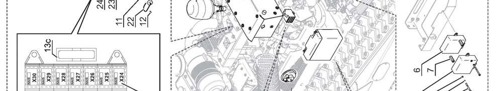
28 Converting the Machine for use with the Manual Control Unit The method of adapting the machine for use with the manual control unit requires attachment of the Control Unit and deactivation of the Brake Control Module; the procedures are as follows; Control Unit Attachment Connect the manual control unit to its connection point on the electronic ignition box, this point is located on the right hand side of the machine as shown in the photos below. Location of connection point for the Manual Control Unit Deactivating the Brake Control Module Under normal operating conditions when using the remote control, movement of the joystick sends a signal to the brake system instructing it to release the brakes. When using the manual control unit the brake controller must be bypassed to allow the brakes to release, this is achieved by disconnecting the wiring loom from the brake control module. The brake control module is located under the bonnet on the right hand side of the machine indicated T in the photographs opposite and below. Remove dust cover and plug unit into the connection point Location of Brake Control Module (T) Brake Control Module identification (indicated T ) Disconnect the wiring loom plug from the Brake Control Module to allow machine operation with Manual Control Note: Failure to disconnect the Brake Control Module will result in the engine stalling when attempting to transport the machine in Manual Control Mode. 21
29 PRE-OPERATION CHECKS WARNING! All checks or inspections of the machine should be performed with the machine parked on firm level ground with the engine switched off and the starting key removed. The following checks should be made daily before using the machine; Check all safety guarding is in good condition and fitted correctly. Check nuts and bolts for tightness, retighten if required. Check flail head for damaged or missing flails replace if required before use. Check oil, coolant and fuel levels, replenish if required. Check filters clean or replace if required. Check radiator matrix is clean clear blockages if required using compressed air. Lubricate machine as per details stated in the maintenance section. Work and Work Area Precautions Always inspect the work area prior to operations; check for and remove foreign bodies such as large stones, metal component, wire and glass etc. which could damage machine component or be ejected by the flail head. Any immoveable object should be visually marked or avoided. Ensure the area is clear of animals and persons. Never manoeuvre the machine into an area where you can no longer see it working. Only work the machine in grass or brushwood that is within its cutting capability; attempting to cut materials beyond the machines capability will damage components. When working on slopes always start at the bottom and work up. Never run the machine down a slope in excess of 50 Never operate the machine on slopes or ground where there is a risk of overturn. 22


.")
30 OPERATION Always wear safety shoes, ear defenders and safety glasses when operating the machine. Always work in good lighting conditions. If necessary, use artificial lighting in compliance with local rules in force. Do not smoke near the machine; oils, fuels and lubricants are flammable. Before moving the machine, ensure that there are no persons, animals, or obstacles in the work zone. Do not change direction whilst moving on kerbs, rocks or surfaces with considerable differences in height (more than 20cm); in these instances always move perpendicular to the obstacles. When reversing uphill, do not steer when transferring from the level surface to the slope, if this is unavoidable, perform the manoeuvre gradually. Do not move along the edge of a slope or on uneven ground with one track in the horizontal position and the other inclined or partially raised (when machine is inclined in excess of 10 ). To avoid risk of track damage, always proceed with both tracks travelling on the same horizontal plane. When the machine manoeuvres over an obstacle, a space is created between the bearing rollers and the track - this can cause the track to come off its seat. The same situation can occur in reverse when a space is created between bearing roller, idler roller, and track. To eliminate this risk, track guides are provided on the front part of the undercarriage. 23


31 If the machines changes direction, and the track cannot move sideways due to the presence of an obstacle, there is a risk that the track can be damaged or come of its seat; wherever possible avoid turning the machine when it is against an obstacle, if unavoidable, make manoeuvres slowly and gradually until clear of the object. If the machine moves in reverse in these conditions, there is risk of the track coming off its seat. If the machine is steered in these conditions, the track will come off its seat. 24
32 MAINTENANCE SECTION Diesel Engine Maintenance For specific service and maintenance information regarding the diesel engine, refer to the engine manufacturer s handbook provided with the machine. Ensure all service and maintenance work on the engine is carried out at the intervals stated in that manual. Maintenance Scheme (General Machine) Every Hour Clean radiator air suction filter. Clean radiator matrix using Clean Fix system or if required using a compressed air line. Clean air intake area around the oil radiator. Clean oil radiator. After Initial 8 Hours - New Machine Check nuts, bolts, pipes and hoses for tightness tighten if required. Check track tension and adjust if required refer to specific section for details. Check hydraulic oil level replenish if required. Clean radiator matrix use compressed air line. Daily Clean radiator using compressed air line. Check hydraulic oil level replenish if required. Check engine oil level replenish if required. Check coolant level replenish if required. Every 50 Working Hours Grease carrying rollers and sliding rollers. Check track tension and adjust if required. After Initial 100 Hours - New Machine Drain and replace hydraulic oil. Replace hydraulic oil filter. Drain and replace engine oil. Replace engine oil filter. Check track tension and adjust if required. Every 100 Working Hours Check alternator belt tension and tighten if required. Replace engine oil. Every 250 Working Hours Drain and replace hydraulic oil. Replace hydraulic oil filter. Drain and replace engine oil. Replace engine oil filter. Replace engine air filter Replace fuel filter 25
33 Maintenance Scheme (Track Components) Daily Checks Check track tension. Check condition of gear motors. Check track condition; replace tracks when there is less than 10mm of tread remaining or sooner if there are visible signs of deep cuts or cracks. Check there are no stones or foreign bodies within the tracks, rollers, gears or sprockets. Monthly Checks Check oil level in gear unit. Check rollers are correctly fastened. Check there is no slack in the bearings. Six Monthly Checks Check wear and tear and overall condition of connections, pinions and lower rollers these must be replaced when they reach their maximum wear limit; refer to wear limits page. Check brakes are working correctly. Check all nuts and bolts for tightness. Periodic Checks Check brakes and safety warning decals are in good condition. Make sure the machine is thoroughly cleaned on a regular basis. Check all fastenings, supports, steel structural parts, welds and pins etc. are in good condition. Ensure paintwork is kept in good condition. Lubricate the tracked undercarriage every 20 working hours. Hydraulic Hoses Hoses and hydraulic connections should be inspected for signs of wear or damage on a regular basis, damaged or worn components must be replaced immediately. The working life of undamaged hoses is approximately six years, they should be replaced after this period. 26


34 Cleaning the Air Filters Grills & Radiator If the machine is running, reduce to minimum revs and allow engine to run for a further minute before switching off remove and pocket the ignition key. Clean outsides of air suction grills before releasing the three rubber hooks and opening the cover. Clean the radiator matrix, inside of the air intake grill and surrounding area using a compressed air line, do not use any tools to clean the radiator that may cause damage to the fins. Close the cover and secure in place with the rubber hooks. Clean air intake grills of the machines front cover to ensure maximum airflow to the engine. Ensure covers are closed and secured correctly to stop dirt getting in. WARNING! If the engine temperature becomes too high a red temperature warning light on the ignition panel will be illuminated to notify the operator where this occurs refer to the engine manufacturer s manual. 27

35 Checking Hydraulic Oil Level The procedure for checking and replenishing the machines hydraulic oil is as follows; Park the machine on a firm level site. Ensure engine is switch off and the key removed and pocketed. Release rubber hooks and raise the front engine cover. Unscrew the dipstick (located under the filler cap), remove and wipe with a clean rag. Replace dipstick without screwing in, then remove again and check the level oil level is correct if the oil reaches the marker on the dipstick. If oil level is too low, top up using PANOLIN HLP SYNTH 46 oil (E2019HLPSE46). When oil level is correct, screw the dipstick back in, close and secure the engine cover. Note: Only use PANOLIN HLP SYNTH 46 oil for topping up and oil changes; failure to use the specified oil will result in a non-compliance of the Warranty. Checking Engine Oil Level The procedure for checking and replenishing the machines engine oil is as follows; Park the machine on a firm level site. Ensure engine is switch off and the key removed and pocketed. Undo the 4 knurled head screws and lower the cover. Remove dipstick and wipe with a clean rag. Replace dipstick then remove again and check the level oil level is correct if the oil reaches the upper marker on the dipstick. If oil level is too low, top up using MOBIL SUPER 3000 X1 5W40 oil (E2022MB05W40). When topping up oil always clean the surrounding area of the filler cap before removal of the cap to avoid the risk of dirt contaminating the oil. When oil level is correct, replace dipstick before raising and securing the cover. Location of engine oil dipstick 28
 The procedure for changing the engine oil and filter is as follows; Park the machine on a firm level site.")

36 Engine Oil Replacement and Filter Change Oil Capacity: 6.1L without filter 6.6L with filter Oil Type: MOBIL SUPER 3000 X1 5W40 (E2022MB05W40) The procedure for changing the engine oil and filter is as follows; Park the machine on a firm level site. Remove drain plug and release the oil into a suitable container ensure the container used has sufficient capacity for the amount of oil. Engine oil drain plug location Once all the oil has been released, replace drain plug and torque to 34.5Nm. Unscrew and remove the engine oil filter Take the new filter and smear some engine oil on the rubber seal before fitting screw the filter hand tight, then turn it approximately a further ¾ of a turn. Remove filler cap and slowly refill with 6.6L of MOBIL SUPER 3000 X1 5W40 engine oil. Replace filler cap and start the engine. Run engine for 5 minutes or so and stop for a further 3 minutes before checking the oil level is correct. NOTE: Used engine oil is both a dangerous waste and a precious raw material; collect it in a suitable container and recycle it. Never pour waste oil into drains or waterways it is harmful and illegal. 29


37 Hydraulic Oil Replacement and Filter Change Hydraulic Oil Tank Capacity: 18 Litres Complete System Capacity: 28 Litres The procedure for changing the hydraulic oil and filter is as follows; Remove the protection plate from the underside of the hydraulic oil tank. Note: Removal of the plate allows access to both the hydraulic tank drain plug and the fuel tank drain plug identify the correct plug before continuing to the next step. Tank protection plate Hydraulic oil tank drain plug Remove drain plug and release the oil into a suitable container. When the oil has drained completely, replace drain plug and refit protection plate. Unscrew and remove the hydraulic oil filter, this is located under the bonnet on the left hand side of the machine the filter can be removed by using either a filter wrench or a hexagonal 19mm spanner. Filter Wrench Hydraulic oil filter location Fit new hydraulic oil filter and tighten securely take care not to over tighten. Note: Always replace filters at the intervals stated in the maintenance schedule using quality original filters as specified and supplied by the manufacturer. Refill the hydraulic oil tank with PANOLIN HLP SYNTH 46 hydraulic oil check using the dipstick until the level is correct. Start engine and allow it to run for 2 minutes. Stop engine and re-check oil level on the dipstick, top up if the level has dropped. Check all components and covers are tightly secured before using the machine. 30 Hydraulic oil tank filler location

38 Hydraulic Distributor Valve The distributor valve that controls the hydraulic functions of the machine is located under the vehicle and is only accessible from beneath the machine. When working on this, or any other item located under the machine, great care must be adopted to ensure the machine is securely positioned before attempting to access or work on the component. WARNING: Never attempt to work under any machine that it not safely supported and chocked using suitable equipment specifically designed for the task and capable of supporting its weight. Access to the valve is gained by removal of the protection plate which is held in position by six bolts. Hydraulic valve protection plate Hydraulic distributor valve 31

39 Fuel Filter Cleaning / Replacement The procedure for cleaning or renewing the fuel filter is as follows; Park the machine on a firm level site, switch the engine off and open the engine cover. Fuel Filter Fuel Supply Tap Close the fuel supply tap located on the filter housing. Place a suitable container under the filter assembly and unscrew the filter bowl securing ring using a filter key. Carefully remove filter bowl using the container underneath to catch spilled fuel - retain sealing ring for subsequent re-attachment. Remove and clean (or renew) the filter element. Clean out the inside of the filter bowl using a clean rag. Re-install the filter and refit the filet bowl ensuring the sealing ring is fitted. Screw the filter bowl securing ring to a point where the sealing ring seats on the housing and tighten further third of a turn. Open tap to restore the fuel supply to the filter. Unscrew the breather screw on the fuel filter by approximately one turn. Place a collecting bowl under the fuel filter. Turn ignition key to position 1, this will switch on the electric fuel pump. Allow the pump to run until fuel (free of bubbles) begins to flow from the breather screw. Screw the breather screw back in. Start the engine. Check components to ensure there is no fuel leakage. WARNING: Do not allow the starter motor to run for more than 30 seconds at a time if the engine fails to start allow at least 2 minutes before re-starting. 32

40 Fuel Filter Water Drain Water will accumulate in the filter bowl that will from time to times need to be purged; the frequency of this task will primarily depend on the quality of the diesel being used. The filter bowl should be regularly inspected, and water drained off as and when required. The procedure for draining the water is as follows; With the engine switched off, place a suitable container under the fuel filter. Open the water drain valve located on the base of the filter bowl. Allow water to run into the container until it is gradually replaced by a flow of fuel. Close the drain valve. Water Drain Valve Priming the Fuel System If at any time the machine runs out of fuel, it will be necessary to prime the fuel system in order to get it running again the procedure for this is as follows; Fill the tank with fuel. Unscrew the breather screw on the fuel filter by approximately one turn. Place a collecting bowl under the fuel filter. Turn ignition key to position 1, this will switch on the electric fuel pump. Allow the pump to run until fuel (free of bubbles) begins to flow from the breather screw. Screw the breather screw back in. Start the engine. WARNING: Do not allow the starter motor to run for more than 30 seconds at a time if the engine fails to start allow at least 2 minutes before re-starting. 33


41 Support Springs The hydraulic rams that position the front mounted flailhead are equipped with support springs, the support pressure offered by the springs can be adjusted to suit differing needs and applications by altering their work position tension. The procedure for adjusting the springs is as follows; Raise the flailhead fully by operation of the hydraulic rams. Remove bolt and washer from the ram rod end and release the chain from the lug. Re-attach the chain selecting an alternative link to either increase or decrease tension. Replace washer and bolt to secure in position. Repeat the process on the opposite ram. Steel Tracks Tracks equipped with steel treads can be supplied as an alternative to the normal all rubber type - the steel tread version has the additional option of being fitted with steel spikes. To fit the spikes remove every second steel tread by removal of the 3 x M8 Allen headed screws, and replace with the steel spike treads using the screws supplied and torque to 70Nm. If a machine is fitted with spikes the operator must avoid driving the machine on any surfaces that would suffer damage from the spikes such roads, car parks, recreation areas etc. unless the machine has been fitted with rubber transport blocks specifically designed to protect surfaces. Transport Blocks Fitment The rubber transport blocks have holes in them that locate on the spikes and are fitted by pushing them onto each set of accessible spikes before slowly driving the machine forward so its weight forces them tightly into place; repeat the process until all the spike sets are fitted with a block. After transportation a lever or large screwdriver will be required to prise the blocks back off the spikes. 34


42 Replacing Tracks Tracks must be changed when only 10mm of tread remains, or before if they show signs of excessive cuts or cracks. The components shown below are constituent parts of the track system illustrated here for identification purposes. Lower Roller Unit Sprocket Assembly Tracked Undercarriage Idler Roller Backstay Rubber Track The procedure for changing the tracks is as follows; WARNING: Never attempt to work on any machine that it not safely supported and chocked using suitable equipment specifically designed for the task and capable of supporting its weight. Ensure suitable safety gear is worn at all times when performing maintenance tasks. Beware, there is pinch risk when working on these components. Raise the machine off the ground to a height of approximately 30-40cm; ensure the machine is stable and suitably supported. Clean undercarriage components and their surrounding area prior to performing maintenance on them. Remove backstay side cover Loosen valve on the tensioner unit to release the grease pressure. Once pressure has been fully released the valve can be removed. Compress the idler roller; this can be done by using your foot to press the track back. Draw the track down and outwards at its mid point on the lower run to pull it off its seating, levering between the track and the idler roller until it is free enough to be removed. Take care to keep clear of the track as it falls to the ground. Installing the new track is basically a reversal of the above tension the track by pumping grease into the tensioner unit to a pressure of 130 Bar. (Max. 150 Bar). 35

43 Track Tension Kit (Optional) A grease tensioner system controls the track tension on the machine. Keeping the tracks correctly tensioned is an important duty that must be carried out at the intervals stated in the maintenance schedule; failure to observe the correct tension can result in the tracks coming off the machine during operations. A Tension Kit, comprising of a grease pump equipped with a manometer, is available as an option for use in correctly checking and setting the pressure. The correct pressure is 130 Bar. (Max. 150 Bar). Track Tension Kit ( ) Wear Limits The track components shown opposite must be replaced when they reach their maximum wear limit, corresponding to 100% in the figures stated below; Lower Rollers Front Cogs Drive Cogs Ø when new 130.0mm 264.0mm 290.0mm Ø at 25% wear 128.0mm 263.0mm 289.0mm Ø at 50% wear 126.0mm 261.5mm 287.5mm Ø at 75% wear 124.0mm 259.5mm 285.5mm Ø at 100% wear 121.0mm 257.0mm 283.0mm Lubrication of Undercarriage Components Components of the tracked undercarriage (rollers, pins, bushings etc.), must be greased every 20 working hours. 36
44 UNDERCARRIAGE SPECIFICATIONS Loading Capacity 1.2T Length 1548mm Axle to axle length 1192mm Track height 479.5mm Crossmember height (from ground) 150mm Fixed undercarriage width 1260mm Number of lower rollers per side (per machine) (8) Number of upper rollers per side (per machine) (2) Track width 230mm Number of links per side (per machine) (94) Chain pitch 72mm Track tensioner pressure (Max) 150Bar Total weight 444kg Hydraulic motor displacement 332cm³ Hydraulic motor pressure (Max) 190Bar Hydraulic flow rate (Max) 39l/min Maximum speed 7km/h Operating temperature range -10/+40 C Maximum operating humidity 95% Brake release pressure range 12-16Bar Maximum gradeability 114% 37
 Fuses & Relays F1 +12V sensors 3 Amp F2 Actuator 3 Amp F3 +12V Park brake 7,5 Amp F4 Hold Solenoid + saftey stopdown 10 Amp F5 Pull Solenoid 30 Amp F6 Unloading Valve 7,5 Amp")
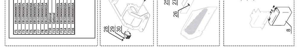
45 ELECTRICAL SYSTEM (Machines Serial No. ROBO onwards) Fuses & Relays F1 +12V sensors 3 Amp F2 Actuator 3 Amp F3 +12V Park brake 7,5 Amp F4 Hold Solenoid + saftey stopdown 10 Amp F5 Pull Solenoid 30 Amp F6 Unloading Valve 7,5 Amp F7 Alternator 5 Amp F8 Horn 15 Amp F9 Manual command 15 Amp F10 Clean Fix fan / Beacon 15 Amp F11 Light warms 5 Amp F12 Fuel pump 7,5 Amp F Hp units 15 Amp F14 +12V Plug 10 Amp F15 Fuse Receiver 7,5 Amp F16 Air filter sensor 3 Amp X95 General fuse 40 Amp X97/R1 Pull Solenoid relay X99/R2 Manual control X97/R2 Air Heater (optional) X99/R3 Beacon lamp X97/R3 Starter relay X99/R4 Clean Fix fan X97/R4 Battery switch X99/R5 Unloading Valve X98/R1 Actuator + X99/R6 Manual comand track R/H X98/R2 Actuator - X99/R7 Manual comand track L/H X98/R3 Horn X100/R1 Check test before start X98/R4 Hyd. oil filter pressure X100/R2 Low fuel level X98/R5 Lower hyd. oil level X100/R3 Engine oil pressure sensor X98/R6 Hold solenoid X100/R4 High water engine temp. X98/R7 Radio-Control switch off X100/R5 Angle sensor (Opt) X99/R1 Radio-Control stop (Link missing) X100/R6 Alternator LED X100/R7 Parking brake relay 38
46 TROUBLESHOOTING Symptom Possible Cause Solution Track damage. Excessive tread wear; Replace track. Loosening/breaking of internal structural steel rope. Track slackens frequently. Faulty tensioner valve. Damaged tensioner seal. Worn tensioner components. Replace valve. Replace seal. Replace worn components. Upper track does not stay in Track slide worn. Replace slide. position. Upper roller worn. Replace upper roller. Lower track does not stay in Lower track guide worn. Replace lower track guide. position. Lower roller worn. Replace lower roller. Track jams when the machine is steering. Oil leakage Excessive noise. Excessive vibration. Overheating Motor runs but gear unit not working. Brake not releasing. Brakes not locking. Material (stones, rocks, earth etc.) trapped between rollers, sprockets, idler roller and track. Hardened seals. Gasket/seals damaged or worn. Internal malfunction. Worn seals. Internal malfunction. Worn seals. Lack of oil. Arduous conditions/hot climate. Brakes binding. Motor wrongly assembled. Internal malfunction. Brake jammed. Lack of brake pressure. Faulty brake seals. Residual pressure in circuit. Worn brake components. Remove material by turning the track in both directions while slackening slightly, raise machine at same time if possible. Clean around component and recheck after a few days. Contact dealer. Contact dealer. Contact dealer. Add oil. Contact dealer. Check brake release pressure. Check coupling between motor and gear unit. Contact dealer. Check braking system. Check brake connections. Contact dealer. Check hydraulic system. Contact dealer. 39
47 40
48 ROBOCUT - Parts Section - 41

49 CHASSIS ASSEMBLY ROBOCUT 42
50 CHASSIS ASSEMBLY ROBOCUT REF. QTY. PART No. DESCRIPTION CHASSIS ASSEMBLY INNER BARREL OUTER BARREL BUSH SPROCKET FORK SPROCKET DRIVE SPROCKET UNDERCARRIAGE HOUSING MOTOR COVER SPRING PIN BUSH COVER PLATE SPACER ROLLER WASHER VALVE HOUSING VALVE VALVE SPRING PIN ROLLER CYLINDRIC HEAD SCREW FLANGED HEAD SCREW FLANGED HEAD SCREW GRUB SCREW LOCK NUT LOCK NUT ROLL PIN COPPER WASHER WASHER KNURLED WASHER BUTTING HEAD FITTING TRACK ROLLER BEARING BEARING CIRCLIP CIRCLIP LH TRACK DRIVE MOTOR RH TRACK DRIVE MOTOR WASHER - Serial No O RING ROLLER SEAL SEAL NUT SCRAPER RING SEAL UPPER ROLLER ASSEMBLY LOWER ROLLER ASSEMBLY 43


51 RUBBER TRACKS ROBOCUT 44
52 RUBBER TRACKS ROBOCUT REF. QTY. PART No. DESCRIPTION RUBBER TRACKS RUBBER TRANSPORT BLOCK BOLT BOLT RUBBER TRACK 250/72/ RUBBER TRACK 280/72/ RIVETED STIRRUP STEEL STIRRUP RUBBER TRACK (MOVEABLE STIRRUPS) 45


53 EQUIPMENT MOUNTING ASSEMBLY ROBOCUT 46
54 EQUIPMENT MOUNTING ASSEMBLY ROBOCUT REF. QTY. PART No. DESCRIPTION EQUIPMENT MOUNTING ASSEMBLY ATTACHMENT MOUNTING FRAME RAM PIN RETAINING COLLAR WASHER RH HOSE SUPPORT BRACKET LH HOSE SUPPORT BRACKET LEFT BULKHEAD FIXING PLATE RIGHT BULKHEAD FIXING PLATE CHAIN BULKHEAD FITTING QR COUPLING QR COUPLING PLUG (Option) QR COUPLING PLUG (Option) HYDRAULIC RAM QR COUPLING PLUG (Option) PLUG (Option) QR COUPLING BULKHEAD FITTING FLANGED HEAD SCREW NUT BOLT NUT CYLINDRIC HEAD SCREW CYLINDRIC HEAD SCREW SPRING FLAT WASHER HOSE CLAMP HOSE CLAMP GREASE NIPPLE SETSCREW FLAT WASHER LOCK NUT FLAT WASHER BAR WASHER GREASE NIPPLE LOCK NUT SCREW BONDED SEAL BONDED SEAL 47
55 ENGINE COVER ASSEMBLY ROBOCUT 48
56 ENGINE COVER ASSEMBLY ROBOCUT REF. QTY. PART No. DESCRIPTION ENGINE COVER ASSEMBLY SIDE MESH CENTRAL LOWER MESH CENTRAL UPPER MESH RADIATOR BONNET AIR FILTER BONNET AIR FILTER BONNET SUPPORT RIGHT SIDE BONNET LEFT SIDE BONNET RADIATOR LEFT SUPPORT RADIATOR RIGHT SUPPORT RADIATOR CLOSING SUPPORT REAR COVER SIDE PROTECTION SUPPORT SCREW CYLINDRIC HEAD SCREW COUNTERSUNK HEAD SCREW HEADLESS SCREW CYLINDRIC HEAD SCREW FLANGED HEAD SCREW FLANGED HEAD SCREW FLANGED HEAD SCREW FLANGED HEAD SCREW AUTOGRIP NUT AUTOGRIP NUT LOCK NUT LOCK NUT BONNET FASTENER WASHER WASHER WASHER WASHER SPRING WASHER ANTI-VIBRATION BLOCK HINGE RADIATOR BONNET COMPLETE 49

57 MACHINE COVER ASSEMBLY ROBOCUT 50
58 MACHINE COVER ASSEMBLY ROBOCUT REF. QTY. PART No. DESCRIPTION MACHINE COVER ASSEMBLY ROLL BAR SUPPORT ROLL BAR BATTERY COVER UPPER BONNET UPPER MESH SIDE MESH FRONT MESH VALVE COVER PLATE TANK COVER PLATE BUSHING OIL SUMP PROTECTION SCREW SCREW HEADLESS SCREW HEX SKT BUTTON HEAD SCREW CYLINDRIC HEAD SCREW FLANGED HEAD SCREW FLANGED HEAD SCREW AUTOGRIP NUT AUTOGRIP NUT LOCK NUT LOCK NUT BONNET FASTENER WASHER WASHER WASHER WASHER WASHER SPRING WASHER SPRING WASHER WASHER (LARGE SERIES) ANTI-VIBRATION BLOCK REMOTE RECEIVER MOUNTING LOCK NUT ANTI-VIBRATION BLOCK ELECTRIC BOX MOUNTING FRAME HEX SKT BUTTON HEAD SCREW WASHER (LARGE SERIES) RUBBER WASHER (LARGE SERIES) ELECTRICAL BOX COVER UPPER BONNET COMPLETE EXTENSION PLATE - Serial No EXTENSION - Serial No WASHER - Serial No LOCK NUT - Serial No HEX HEAD SCREW - Serial No WASHER - Serial No LOCK NUT - Serial No FLANGED HEAD SCREW - Serial No
59 DIESEL ENGINE ASSEMBLY ROBOCUT 52
60 DIESEL ENGINE ASSEMBLY ROBOCUT REF. QTY. PART No. DESCRIPTION DIESEL ENGINE ISUZU ENGINE (40HP) MOTOR BELT AIR FILTER MOUNTING FLANGED HEAD SCREW AUTOGRIP NUT FLANGED HEAD SCREW RADIATOR BRACKET SETSCREW WASHER (LARGE SERIES) ANTI-VIBRATION RUBBER SPACER WASHER (LARGE SERIES) SETSCREW RADIATOR MOUNTING BRACKET AUTOGRIP NUT WASHER HEADLESS SCREW ANTI-VIBRATION MOUNTING SPACER RADIATOR HOSE CLIP AIR FILTER COMPLETE c/w CLIP RADIATOR HOSE LEFT RADIATOR HOSE RIGHT LEFT MESH GUARD FLANGED HEAD SCREW RADIATOR PROTECTION UPPER MESH GUARD RIGHT MESH GUARD SCREW WASHER WASHER ANTENNA BRACKET WASHER SPRING WASHER SETSCREW LIGHT BRACKET CLIP RUBBER HOSE AIR FILTER BRACKET AIR FILTER HOUSING AIR FILTER COVER Continued... 53
61 DIESEL ENGINE ASSEMBLY ROBOCUT 54
62 DIESEL ENGINE ASSEMBLY ROBOCUT REF. QTY. PART No. DESCRIPTION DIESEL ENGINE (Continued) SECONDARY AIR FILTER PRIMARY AIR FILTER FILTER HOUSING CAP RUBBER VALVE CLOGGING SENSOR ALTERNATOR LID FLANGED HEAD SCREW EXHAUST SUPPORT EXHAUST MANIFOLD NUT CLIP EXHAUST SILENCER 55


63 DIESEL ENGINE COMPONENTS ROBOCUT 56
64 DIESEL ENGINE COMPONENTS ROBOCUT REF. QTY. PART No. DESCRIPTION DIESEL ENGINE COMPONENTS OIL SENSOR SOLENOID - ELECTRICAL STOP ALTERNATOR STARTER MOTOR SOLENOID - STARTER MOTOR DIPSTICK SETSCREW WASHER KNURLED WASHER CYLINDRIC HEAD SCREW SILENCING WASHER HEX SKT BUTTON HEAD SCREW REAR ANTI-VIBRATION MOUNTING WASHER WASHER AUTOGRIP NUT ANTI-VIBRATION BLOCK AUTOGRIP NUT LH ENGINE MOUNTING - Serial No ENGINE MOUNTING - Serial No RH ENGINE MOUNTING - Serial No ENGINE MOUNTING - Serial No CYLINDRIC HEAD SCREW FRONT ANTI-VIBRATION MOUNTING ENGINE OIL FILTER FUEL FILTER WATER SENSOR - Serial No WATER SENSOR - Serial No WATER SENSOR - Serial No COPPER WASHER SUCTION STRAINER OIL SUMP FLANGED HEAD SCREW FLANGED HEAD SCREW COPPER WASHER PLUG 57


65 PUMPS ASSEMBLY ROBOCUT 58
66 PUMPS ASSEMBLY ROBOCUT REF. QTY. PART No. DESCRIPTION PUMPS ASSEMBLY FLYWHEEL PUMP ADAPTOR KNURLED WASHER HEX HEAD SCREW FLYWHEEL FLANGED HEAD SCREW PUMP MANIFOLD GROOVED JOINT ROTOR PUMP PUMP CLAMP LOCK WASHER HEX HEAD SCREW TANDEM PISTON PUMP - Serial No TANDEM PISTON PUMP - Serial No CYLINDRIC HEAD SCREW WASHER GEAR PUMP O RING PISTON PUMP HEX HEAD SCREW CONNECTOR 59
67 ACTUATOR ASSEMBLY ROBOCUT 60
68 ACTUATOR ASSEMBLY ROBOCUT REF. QTY. PART No. DESCRIPTION ACTUATOR ASSEMBLY BRACKET COUNTERSUNK HEAD SCREW FLANGED HEAD SCREW ACTUATOR AUTOGRIP NUT WASHER HEX HEAD SCREW FLANGED HEAD SCREW THROTTLE BRACKET ACTUATOR ARM THROTTLE SPRING ACTUATOR SPRING LINKAGE AUTOGRIP NUT 61

69 REVERSIBLE FAN SYSTEM ROBOCUT 62
70 REVERSIBLE FAN SYSTEM ROBOCUT REF. QTY. PART No. DESCRIPTION REVERSIBLE FAN ASSEMBLY REVERSIBLE FAN FLANGE FLANGED HEAD SCREW FLANGED HEAD SCREW BLADE SET FOR FAN (3 BLADES) COMPRESSOR COMPRESSOR PLATE (OUTER) COMPRESSOR PLATE (INNER) FLANGED NUT COMPRESSOR CLAMP WASHER CYLINDRIC HEAD SCREW HOSE CLAMP FAN COMPRESSOR c/w FITTINGS FAN COMPRESSOR FILTER AIR HOSE COMPLETE SAFETY RING GASKET FRONT FLANGE ECCENTRIC PIN SQUARE SEALING RING PISTON SPRING REAR FLANGE CYLINDRIC HEAD SCREW PIPE KIT AIR HOSE 63


71 DIESEL FUEL CIRCUIT ROBOCUT 64
72 DIESEL FUEL CIRCUIT ROBOCUT REF. QTY. PART No. DESCRIPTION DIESEL FUEL CIRCUIT PRIMARY FUEL FILTER FUEL FILTER CAP PRIMARY FILTER CARTRIDGE HEX HEAD SCREW WASHER HOSE CLAMP DIESEL HOSE mm 7A DIESEL HOSE - 870mm 7B DIESEL HOSE - 260mm 7C DIESEL HOSE mm FUEL PUMP FLANGED HEAD SCREW WASHER AUTOGRIP NUT CYLINDRIC HEAD SCREW SPRING WASHER WASHER FUEL LEVEL SENSOR FUEL CAP FLANGED HEAD SCREW PLUG FUEL TANK 65


73 OIL TANK ASSEMBLY ROBOCUT 66
74 OIL TANK ASSEMBLY ROBOCUT REF. QTY. PART No. DESCRIPTION OIL TANK ASSEMBLY OIL TANK FLANGED HEAD SCREW PLUG LEVEL SENSOR OIL CAP / LEVEL OIL FILTER SENSOR BRACKET FILTER CLOGGING SWITCH OIL FILTER HOUSING OIL FILTER ELEMENT 67


75 ELECTRICAL COMPONENTS ROBOCUT (Machine Serial No ) 68
76 ELECTRICAL COMPONENTS ROBOCUT (Machine Serial No ) REF. QTY. PART No. DESCRIPTION ELECTRICAL COMPONENTS Machine Serial No BEACON BEACON CONNECTION CYLINDRIC HEAD SCREW SPRING WASHER WASHER MICROPROCESSOR NUT BATTERY EMERGENCY SWITCH (RED) PLUG 12V CONNECTOR PLUG (FEMALE) COUNTERSUNK SCREW RELAYS / FUSE BOX 13a RELAY WITH DIODE 13b MICRO RELAY 13c FUSE (40A) IGNITION SWITCH WATER TEMPERATURE INDICATOR HOURS COUNTER HEX SKT BUTTON HEAD SCREW LOCK NUT FEMALE CONNECTOR FLANGED HEAD SCREW WASHER AUTOGRIP NUT INJECTION PUMP DELAY PRE AIR HEATER HORN (12V) FLANGED HEAD SCREW NUT AUTOGRIP NUT WASHER (LARGE SERIES) SHUNT BOX FLANGED HEAD SCREW YELLOW LED RED LED ELECTRICAL BOX INSTRUMENT PANEL ELECTRICAL BOX ASSEMBLY 69


77 ELECTRICAL COMPONENTS ROBOCUT (Machine Serial No ) 70
78 ELECTRICAL COMPONENTS ROBOCUT (Machine Serial No ) REF. QTY. PART No. DESCRIPTION ELECTRICAL COMPONENTS Machine Serial No BEACON BEACON CONNECTION CYLINDRIC HEAD SCREW SPRING WASHER WASHER MICROPROCESSOR NUT BATTERY EMERGENCY SWITCH (RED) PLUG 12V FEMALE CONNECTOR HEX SKT BUTTON HEAD SCREW RELAYS / FUSE BOX 13a RELAY WITH DIODE 13b MICRO RELAY 13c FUSE (40A) IGNITION SWITCH PRE AIR HEATER HOURS COUNTER ELECTRICAL BOX ASSEMBLY FLANGED HEAD SCREW WASHER AUTOGRIP NUT ELECTRICAL SYSTEM COMPLETE CONNECTOR PLUG (FEMALE) WASHER LOCK NUT HORN (12V) FLANGED HEAD SCREW NUT LOCK NUT WASHER (LARGE SERIES) SHUNT BOX FLANGED HEAD SCREW ELECTRICAL UNIT ELECTRICAL UNIT ELECTRICAL BOX INJECTION PUMP DELAY WIRING LOOM (CUTTING HEAD) WIRING LOOM (DISTRIBUTOR) BATTERY CABLE (POSITIVE) BATTERY CABLE (NEGATIVE) WIRING LOOM (STARTER/ALTERNATOR) POWER LINE (RECEIVER) 71
79 ELECTRICAL WIRING ROBOCUT 72
80 ELECTRICAL WIRING ROBOCUT REF. QTY. PART No. DESCRIPTION ELECTRICAL WIRING WAY MALE CONNECTOR WAY MALE CONNECTOR WAY MALE CONNECTOR WAY FEMALE CONNECTOR WAY MALE CONNECTOR WAY FEMALE CONNECTOR WAY FEMALE CONNECTOR POLE FEMALE CONNECTOR POLE FEMALE CONNECTOR CONNECTOR RUBBER CABLE SLEEVE WAY CONNECTOR WIRING LOOM (DISTRIBUTOR) WAY CONNECTOR WAY FEMALE CONNECTOR CONNECTOR RUBBER CABLE SLEEVE SLIDE FOR 24-WAY CONNECTOR WIRING LOOM (CUTTING HEAD) BATTERY CABLE (POSITIVE) BATTERY CABLE (NEGATIVE) WIRING LOOM (STARTER MOTOR) WIRING LOOM (RECEIVER) WIRING LOOM COMPLETE 73
81 TRANSMITTING / RECEIVING UNITS ROBOCUT 74
82 TRANSMITTING / RECEIVING UNITS ROBOCUT REF. QTY. PART No. DESCRIPTION CONTROL TRANSMITTING/RECEIVING UNITS AERIAL (ANTENNA) ANTENNA (EUR) ANTENNA (USA) VIBRATION DAMPER KIT MOTHERBOARD (Requires Serial No. of R/C ) ARM CASING (Requires Serial No. of R/C ) ADDRESS KEY (Requires Serial No. of R/C ) WAIST BELT WAIST BELT XXL (Optional) SOCKET PROPORTIONAL JOYSTICK (DUAL AXIS) LOWER CONTROL UNIT (Requires Serial No. of R/C ) TOGGLE SWITCH (ON)-OFF-(ON) TOGGLE SWITCH ON-OFF-ON TOGGLE SWITCH (ON)-ON TOGGLE SWITCH ON-ON TOGGLE SWITCH 2 POLES ON-OFF-ON PUSH-BUTTON (BLACK) STOP PUSH-BUTTON PUSH-BUTTON (GREEN) POTENTIOMETRIC SELECTOR RADIO MODULE (EUR) RADIO MODULE (USA) UPPER CONTROL UNIT (Requires Serial No. of R/C ) CONTROL UNIT FRAME KIT CARD (4 LEDS) JOYSTICK GAITOR CODER CARD (Requires Serial No. of R/C ) BATTERY CHARGER - EUR BATTERY CHARGER - USA (Optional) REMOTE CONTROL BATTERY MANUAL CONTROLLER - Machine Serial No MANUAL CONTROLLER - Machine Serial No TRANSMITTER (EUR) TRANSMITTER (USA - AUS) RADIO R/CONTROL RECEIVER (USA-AUS) RADIO R/CONTROL RECEIVER (EUR) RECEIVER / TRANSMITTER SET (EUR) RECEIVER / TRANSMITTER SET (USA-AUS) 75
83 TRANSMITTING / RECEIVING UNITS (Pure Models) ROBOCUT 76
84 TRANSMITTING / RECEIVING UNITS (Pure Models) ROBOCUT REF. QTY. PART No. DESCRIPTION CONTROL TRANSMITTING/RECEIVING UNITS AERIAL (ANTENNA) ANTENNA (EUR) ANTENNA (USA) SWITCH COVER START KEY CONNECTOR KIT START KEY PROPORTIONAL JOYSTICK (SINGLE AXIS) WAIST BELT WAIST BELT XXL (Optional) SOCKET PROPORTIONAL JOYSTICK (DUAL AXIS) LOWER CONTROL UNIT (Requires Serial No. of R/C ) TOGGLE SWITCH (ON)-OFF-(ON) TOGGLE SWITCH ON-OFF-(ON) TOGGLE SWITCH ON-(ON) TOGGLE SWITCH (ON)-ON TOGGLE SWITCH ON-OFF-ON PUSH-BUTTON (BLACK) STOP PUSH-BUTTON PUSH-BUTTON (GREEN) POTENTIOMETRIC SELECTOR RADIO MODULE (EUR) RADIO MODULE (USA) UPPER CONTROL UNIT (Requires Serial No. of R/C ) CONTROL UNIT FRAME KIT CARD (4 LEDS) JOYSTICK GAITOR CODER CARD (Requires Serial No. of R/C ) BATTERY CHARGER V - USA BATTERY CHARGER - EUR BATTERY CHARGER 110V - USA REMOTE CONTROL BATTERY TRANSMITTER (EUR) TRANSMITTER (USA - AUS) RECEIVER UNIT 870MHZ / TRANSMITTER KEY RECEIVER UNIT 915MHZ / TRANSMITTER KEY REMOTE CONTROL KIT (870MHZ) REMOTE CONTROL KIT (915MHZ) SHOULDER BELT CONNECTOR MANUAL CONTROLLER - Machine Serial No MANUAL CONTROLLER - Machine Serial No


85 INTAKE & DRAIN PUMPS ROBOCUT (Machine Serial No ) 78
86 INTAKE & DRAIN PUMPS ROBOCUT (Machine Serial No ) REF. QTY. PART No. DESCRIPTION INTAKE & DRAIN PUMPS Machine Serial No HYDRAULIC HOSE HYDRAULIC HOSE HYDRAULIC HOSE HYDRAULIC HOSE HYDRAULIC HOSE HYDRAULIC HOSE HYDRAULIC HOSE HYDRAULIC HOSE HYDRAULIC HOSE CONNECTOR CONNECTOR CONNECTOR CONNECTOR CONNECTOR CYLINDRIC HEAD SCREW SPRING WASHER PUMP CONNECTION CHECK COUPLING CHECK COUPLING FEMALE PLUG O RING O RING O RING VALVE BLOCK BRACKET FLANGED HEAD SCREW OIL MANIFOLD VALVE BLOCK FLANGED HEAD SCREW 79


87 INTAKE & DRAIN PUMPS ROBOCUT (Machine Serial No ) 80
88 INTAKE & DRAIN PUMPS ROBOCUT (Machine Serial No ) REF. QTY. PART No. DESCRIPTION INTAKE & DRAIN PUMPS Machine Serial No HYDRAULIC HOSE HYDRAULIC HOSE HYDRAULIC HOSE HYDRAULIC HOSE HYDRAULIC HOSE HYDRAULIC HOSE HYDRAULIC HOSE HYDRAULIC HOSE HYDRAULIC HOSE CONNECTOR CONNECTOR CONNECTOR CONNECTOR CONNECTOR CYLINDRIC HEAD SCREW SPRING WASHER PUMP CONNECTION CHECK COUPLING CHECK COUPLING HEX HEAD SCREW O RING O RING O RING VALVE BLOCK BRACKET FLANGED HEAD SCREW OIL MANIFOLD VALVE BLOCK SPRING WASHER FLAT WASHER 81


 82")

89 CHANGE OVER VALVE CIRCUIT ROBOCUT (Machine Serial No ) 82
90 CHANGE OVER VALVE CIRCUIT ROBOCUT (Machine Serial No ) REF. QTY. PART No. DESCRIPTION CHANGE OVER VALVE CIRCUIT Machine Serial No HYDRAULIC HOSE HYDRAULIC HOSE HYDRAULIC HOSE HYDRAULIC HOSE HYDRAULIC HOSE HYDRAULIC HOSE CONNECTOR CONNECTOR O RING FLANGED HEAD SCREW CHANGE OVER VALVE VALVE PLATE COUNTERSUNK HEAD SCREW WASHER LOCK NUT 83


91 TRACKS HYDRAULIC CIRCUIT ROBOCUT (Machine Serial No ) 84
92 TRACKS HYDRAULIC CIRCUIT ROBOCUT (Machine Serial No ) REF. QTY. PART No. DESCRIPTION TRACKS HYDRAULIC CIRCUIT Machine Serial No HYDRAULIC HOSE HYDRAULIC HOSE HYDRAULIC HOSE HYDRAULIC HOSE HYDRAULIC HOSE HYDRAULIC HOSE HYDRAULIC HOSE HYDRAULIC HOSE HYDRAULIC HOSE HYDRAULIC HOSE HYDRAULIC HOSE HYDRAULIC HOSE CONNECTOR CONNECTOR CONNECTOR TEE FITTING CONNECTOR CONNECTOR CONNECTOR O RING CHECK COUPLING CYLINDRIC HEAD SCREW SPEED-BRAKE VALVE 85


93 TRACKS HYDRAULIC CIRCUIT ROBOCUT (Machine Serial No ) 86
94 TRACKS HYDRAULIC CIRCUIT ROBOCUT (Machine Serial No ) REF. QTY. PART No. DESCRIPTION TRACK HYDRAULIC CIRCUIT Machine Serial No HYDRAULIC HOSE HYDRAULIC HOSE HYDRAULIC HOSE HYDRAULIC HOSE HYDRAULIC HOSE HYDRAULIC HOSE HYDRAULIC HOSE HYDRAULIC HOSE HYDRAULIC HOSE HYDRAULIC HOSE HYDRAULIC HOSE HYDRAULIC HOSE CONNECTOR CONNECTOR CONNECTOR BONDED SEAL CONNECTOR CONNECTOR CONNECTOR O RING CHECK COUPLING CYLINDRIC HEAD SCREW SPEED-BRAKE VALVE HEXAGON SPACER SPRING WASHER WASHER PLUG 87

95 HYDRAULIC RAMS CIRCUIT ROBOCUT 88
96 HYDRAULIC RAMS CIRCUIT ROBOCUT REF. QTY. PART No. DESCRIPTION HYDRAULIC RAMS CIRCUIT HYDRAULIC HOSE HYDRAULIC HOSE HYDRAULIC HOSE HYDRAULIC HOSE CONNECTOR CONNECTOR TEE FITTING 89


97 HYDRAULIC EQUIPMENT CIRCUIT ROBOCUT 90
98 HYDRAULIC EQUIPMENT CIRCUIT ROBOCUT REF. QTY. PART No. DESCRIPTION HYDRAULIC EQUIPMENT CIRCUIT HYDRAULIC HOSE HYDRAULIC HOSE HYDRAULIC HOSE HYDRAULIC HOSE HYDRAULIC HOSE HYDRAULIC HOSE HYDRAULIC HOSE CONNECTOR CONNECTOR O RING O RING 91
99 FLAILHEAD ASSEMBLY ROBOCUT Items # 23 & 39 refer to notes in parts list important information on these components 92
100 FLAILHEAD ASSEMBLY ROBOCUT REF. QTY. PART No. DESCRIPTION FLAILHEAD ASSEMBLY CYLINDER FIXING STIRRUP RUBBER SUPPORT UPPER PROTECTION SUPPORT RAM BRACKET HYDRAULIC RAM HEAD CASING (1.3m) CLAMP STRIP RUBBER FLAP ROTOR (1.3m) ROTOR BEARING SUPPORT HEAD PIVOT BRACKET PIVOT JOINT ROLLER ROLLER BRACKET - R/H ROLLER BRACKET - L/H LEFT SKID WASHER PLATE RIGHT SKID MOTOR MOUNTING PLATE BELT COVER FRONT HOOD SPRING BRACKET (Fits Spring only) SPRING BRACKET (Fits Springs & ) SPRING TENSIONER FIXING SPRING TENSIONER Y-FLAILS KIT (SINGLE STATION) Y-FLAILS KIT (22 STATION) SCREW SCREW SCREW SCREW SCREW SCREW SCREW SCREW SCREW SCREW SCREW NUT SPRING (Item now obsolete use Spring ) SPRING (Not compatible with Spring Bracket ) When replacing the now obsolete early type Spring with the later type Spring the early type Bracket must also be replaced with later type bracket
101 FLAILHEAD ASSEMBLY ROBOCUT Items # 23 & 39 refer to notes in parts list important information on these components 94
102 FLAILHEAD ASSEMBLY ROBOCUT REF. QTY. PART No. DESCRIPTION FLAILHEAD ASSEMBLY LOCK NUT FLANGED NUT LOCK NUT LOCK NUT WASHER WASHER WASHER WASHER SPRING WASHER WASHER WASHER GREASER GREASER BEARING ROLLER BEARING TAPERLOCK BUSH CIRCLIP RETAINING RING CIRCLIP MOTOR CONICAL BUSH PULLEY PULLEY TRAPEZOIDAL TOOTHED BELT OILSEAL OIL SEAL GUIDE FOR OIL SEAL BUSH WASHER SEAL KIT FOR MOTOR
103 ROTORS & FLAILS ROBOCUT 96
104 ROTORS & FLAILS ROBOCUT REF. QTY. PART No. DESCRIPTION ROTORS & FLAILS ASSEMBLY M ROTOR (Y-FLAILS TYPE) STEEL BUSHING Y-FLAIL (6mm) HAMMER FLAIL M ROTOR (HAMMER FLAIL TYPE) BUSHING M ROTOR C/W Y-FLAILS M ROTOR C/W HAMMER FLAILS SCREW SCREW AUTOGRIP NUT AUTOGRIP NUT SINGLE STATION FLAIL KITS Y-FLAILS KIT (6mm Flail) HAMMER FLAIL KIT 22 STATION FLAIL KIT Y-FLAILS KIT (6mm Flail) 97
105 ROBOCUT DECAL KIT ROBOCUT REF. QTY. PART No. DESCRIPTION ROBOCUT DECAL KIT DECAL - MCCONNEL ROUNDEL DECAL - ROBOCUT DECAL - ROBOCUT DECAL - ROBOCUT (OVERLAY) 98
106 SERVICE PARTS - Filters & Filter Cartridges ROBOCUT FUEL FILTER (Part No ) OIL FILTER (Part No ) PRIMARY FUEL FILTER Fitted to Early Models HYDRAULIC OIL FILTER CARTRIDGE (Part No ) Fitted to Later Models HYDRAULIC OIL FILTER CARTRIDGE (Part No ) PRIMARY AIR FILTER CARTRIDGE (Part No ) SECURITY AIR FILTER CARTRIDGE (Part No ) 99
107

108 McConnel Limited, Temeside Works, Ludlow, Shropshire SY8 1JL. England. Telephone: Facsimile:
McCONNEL ROBOCUT REMOTE CONTROLLED MOWER. Operator & Parts Manual Machines 07/13 onwards
 Publication 679 August 2011 Part No. 22674.79 Revision: 11.11.14 REMOTE CONTROLLED MOWER Operator & Parts Manual Machines 07/13 onwards IMPORTANT VERIFICATION OF WARRANTY REGISTRATION DEALER WARRANTY INFORMATION
McCONNEL PASTURATER 2.5M & 3.0M Linkage Mounted Aerators
 Publication 161 February 1991 Part No. 1092850 Revised: 10.06.15 McCONNEL PASTURATER 2.5M & 3.0M Linkage Mounted Aerators Operation & Parts Manual IMPORTANT VERIFICATION OF WARRANTY REGISTRATION DEALER
TWOSE Manure Spreader
 TWOSE OPERATOR MANUAL Publication 668 Part No.22674.68 Twose of Tiverton Limited 6 Chinon Court, Lower Moor Way, Tiverton Business Park, Tiverton, Devon. EX16 6SS. Telephone: (01884) 253691 Fax: (01884)
DITCH KING & DITCH BOSS. Tractor Mounted Digger. Operation & Parts Manual
 Publication 106 (Issue 4) October 1984 Part No. 7118850 Revision: January 1993 DITCH KING & DITCH BOSS Tractor Mounted Digger Operation & Parts Manual IMPORTANT VERIFICATION OF WARRANTY REGISTRATION DEALER
DRUM MOWERS DR165 / DR185 / DR220
 DRUM MOWERS DR165 / DR185 / DR220 INSTRUCTION & PARTS MANUAL Publication 505 Part No.41571.05 Twose of Tiverton Limited 6 Chinon Court, Lower Moor Way, Tiverton Business Park, Tiverton, Devon. EX16 6SS.
Trident 7600HD. Trident 7600HD. Edition June 2014 Part No
 Edition 1.0 - June 2014 Part No. 8999082 1 IMPORTANT VERIFICATION OF WARRANTY REGISTRATION DEALER WARRANTY INFORMATION & REGISTRATION VERIFICATION It is imperative that the selling dealer registers this
LOG CHOP. Hydraulic Wood Guillotine. Owners Illustrated Instruction Book & Parts List
 LOG CHOP Hydraulic Wood Guillotine Owners Illustrated Instruction Book & Parts List Grovebury Road, Leighton Buzzard, Bedfordshire. LU7 4UX. UK. Tel:01525 375157. Fax:01525 385222. Email: enquires@brownsagricultural.co.uk
PART'S MANUAL. Rear Mounted Blade RHINO
 850 Revised 06-10 PART'S MANUAL Rear Mounted Blade Part No. 00787017P An Operator's Manual was shipped with the equipment in the Manual Canister. This Operator's Manual is an integral part of the safe
TWOSE CUTTER GRABS CG10S / CG20S / CG25S / CG30S (Machines 05/07 onwards) Operation & Parts Manual
 Operation & Parts Manual") TWOSE CUTTER GRABS CG10S / CG20S / CG25S / CG30S (Machines 05/07 onwards) Operation & Parts Manual Publication 612 (Rev.05.02.10) IMPORTANT VERIFICATION OF WARRANTY REGISTRATION DEALER WARRANTY INFORMATION
TWOSE CUTTER GRABS CG10S / CG20S / CG25S / CG30S (Machines 05/07 onwards) Operation & Parts Manual Publication 612 (Rev.05.02.10) IMPORTANT VERIFICATION OF WARRANTY REGISTRATION DEALER WARRANTY INFORMATION
1.2M MULTICUT FLAILHEAD
 Publication 666 January 2011 Part No. 22674.66 Revised: 16.12.14 1.2M MULTICUT FLAILHEAD SLIDING HEAD / QUAD DRIVE ROTOR 65HP Build (7354871 & variants) 85HP Build (7354886 & variants) Operator & Parts
Grizzly 52. Tree Cutter. OPERATOR S MANUAL with PARTS LISTING. ALAMO INDUSTRIAL 1502 E. Walnut Seguin, Texas
 Grizzly 52 Tree Cutter Published (06-05) Part No. 02975192 OPERATOR S MANUAL with PARTS LISTING ALAMO INDUSTRIAL 1502 E. Walnut Seguin, Texas 78155 830-379-1480 2005 Alamo Group Inc. An Alamo Group Company
RHD OFFSET SERIES 160/190/225 Flail Mowers
 RHD OFFSET SERIES 160/190/225 Flail Mowers Edition 1.3 - August 2016 Part No. 8999071 1 2 3 4 CE Declaration of Conformity, Conforming to EU Machinery Directive 2006/42/EC We, Spearhead Machinery Ltd,
ROTARY BRUSH CUTTERS THE LEADER OF THE PACK OWNER/OPERATOR SAFETY & INSTRUCTION MANUAL
 72 M-AX ROTARY BRUSH CUTTERS THE LEADER OF THE PACK OWNER/OPERATOR SAFETY & INSTRUCTION MANUAL CONTENTS Page 1. Introduction..................................2 2. Safety Instructions...........................3-4
OPERATIONS MANUAL LEVER CHAIN HOIST
 OPERATIONS MANUAL LEVER CHAIN HOIST IMPORTANT SAFETY INFORMATION Please read, understand and follow all safety information contained in these instructions prior to the use of this hoist. Retain these instructions
2 TONNE TROLLEY JACK
 2 TONNE TROLLEY JACK 61829 IMPORTANT: Please read these instructions carefully to ensure the safe and effective use of this product and save these instructions for future reference. This manual has been
SIP Direct Drive Oil-Lube Air Compressors - Operating & Maintenance Instructions
 SIP Direct Drive Oil-Lube Air Compressors - Operating & Maintenance Instructions Please read and fully understand the instructions in this manual before operation. Keep this manual safe for future reference.
3.25 Ton Heavy Duty Floor Jack
 Please dispose of packaging for the product in a responsible manner. It is suitable for recycling. Help to protect the environment, take the packaging to the local amenity tip and place into the appropriate
RED23305 Owner s Manual
 RED23305 Owner s Manual 5 foot, 3-Point Mounted Snow Blower 270 West Park Avenue Huron, SD 57350 866-526-5682 Serial Number: Date of Purchase: Red Devil Snow Blower See Figure 1. 1. The Red Devil Snow
Trench Filler for Compact Utility Loaders
 Form No. 3353-608 Rev A Trench Filler for Compact Utility Loaders Model No. 22472 260000001 and Up Operator s Manual Register your product at www.toro.com Original Instructions (EN) Contents Page Introduction................................
LOG SPLITTER. Heavy Duty PTO Driven. Owners Illustrated Instruction Book & Parts List
 LOG SPLITTER Heavy Duty PTO Driven Owners Illustrated Instruction Book & Parts List Grovebury Road, Leighton Buzzard, Bedfordshire. LU7 4UX. UK. Tel:01525 375157. Fax:01525 385222. Email: enquires@brownsagricultural.co.uk
Mod: KLD6-12/35XLAS-N
 12/2011 Mod: KLD6-12/35XLAS-N Production code: 1914070 INSTRUCTION MANUAL LOGIC LINE PLUS HOOD Reseller Stamp for Warranty Dear customer, Above all, thank you for choosing our product and we would like
BALLAST ROLLERS INLINE & TANDEM. Publication No:
 BALLAST ROLLERS INLINE & TANDEM Publication No: 5291 08 05 IMPORTANT VERIFICATION OF WARRANTY REGISTRATION DEALER WARRANTY INFORMATION & REGISTRATION VERIFICATION It is imperative that the selling dealer
TC07 TURF CUTTER Operating Instructions
 TC07 TURF CUTTER Operating Instructions Before commissioning the machine, read operating instructions and observe warning and safety instructions. Tracmaster Ltd CAMON TC07 Turf Cutter Manufacturer Details
Operator's Manual. VC-60 & VC-60 Plus Harper Industries, Inc. 7/03 Part No
 Operator's Manual VC-60 & VC-60 Plus 2003 Harper Industries, Inc. 7/03 Part No. 970066 Thank you for purchasing a Harper/Goossen Verti-Cutter. As with all Harper/Goossen products, the Harper/Goossen Verti-Cutter
BOX BLADES PART'S MANUAL SBX/MBX/RO. RHINO 1020 S. Sangamon Ave. Gibson City, IL
 Published 03/6 BOX BLADES PART'S MANUAL SBX/MBX/RO P/N 0078930P An Operator's Manual was shipped with the equipment in the Manual Canister. This Operator's Manual is an integral part of the safe operation
3 TONNE TROLLEY JACK
 3 TONNE TROLLEY JACK 16407 These instructions accompanying the product are the original instructions. This document is part of the product, keep it for the life of the product passing it on to any subsequent
3 Ton Trolley Jack. Please read and fully understand the instructions in this manual before operation. Keep this manual safe for future reference.
 Please dispose of packaging for the product in a responsible manner. It is suitable for recycling. Help to protect the environment, take the packaging to the local amenity tip and place into the appropriate
Heavy-Duty Drywall Dolly Cart
 Heavy-Duty Drywall Dolly Cart Owner s Manual WARNING: Read carefully and understand all ASSEMBLY AND OPERATION INSTRUCTIONS before operating. Failure to follow the safety rules and other basic safety precautions
MOTORINI GP 50. User s Manual.
 MOTORINI GP 50 User s Manual www.motorini.co.uk Dear user: Thank you for choosing to buy a Motorini GP 50 This manual provides the correct operation and maintenance methods for safe riding and maintaining
SLR / SLR-S/N. Instruction Manual. Walrus America Inc
 SLR / SLR-S/N Instruction Manual Walrus America Inc 1. Installation and Connection 1.1. Pump Installation The pump should be sited in a well ventilated and frost-free position. The distance between pumps-motors
Spearhead QHD Flail Mowers. Q2000HD, Q25000HD & Q2800HD Flail Mowers
 Q2000HD, Q25000HD & Q2800HD Flail Mowers 13 th Edition March 2015 1 IMPORTANT VERIFICATION OF WARRANTY REGISTRATION DEALER WARRANTY INFORMATION & REGISTRATION VERIFICATION It is imperative that the selling
Uniprep 2 Rotary scraping tool for pipes mm
 Operating instructions and specifications for Uniprep 2 Rotary scraping tool for pipes 125-500mm Products by innovation not imitation Helping you make the right connections Models covered by this manual:
Section 4.3. Machine Operation - Operating Procedures. Before Starting the Engine: General Pre-Start Inspection
 Section 4.3 Machine Operation - Operating Procedures Before Starting the Engine: General Pre-Start Inspection... 4.3.2 Engine Starting Procedure... 4.3.2 Cold Weather Start-Up... 4.3.3 Engine Shutdown
4400-Lb. Capacity Pallet Jack
 Read carefully and understand all ASSEMBLY AND OPERATION INSTRUCTIONS before operating. Failure to follow the safety rules and other basic safety precautions may result in serious personal injury. Item#
Roller Door Operator
 INSTALLATION INSTRUCTIONS AND OWNERS MANUAL Roller Door Operator IMPORTANT PLEASE READ THESE INSTRUCTIONS CAREFULLY PRIOR TO COMMENCING THE INSTALLATION OF THE OPERATOR UNIT CAUTION This Automatic Opener
FTFR Maintenance and Parts Manual SQ-1 FLOOR TRUSS FINISH ROLLER. Operators Manual
 FTFR Maintenance and Parts Manual SQ-1 FLOOR TRUSS FINISH ROLLER Operators Manual FOREWORD This manual explains the proper maintenance of Square 1 Design Floor Truss Finish Roller as well as the daily
USER MANUAL. CareCo (UK) Ltd, Hubert Road, Brentwood, Essex, CM14 4JE PAGE 1
 Ltd, Hubert Road, Brentwood, Essex, CM14 4JE PAGE 1") by USER MANUAL CareCo (UK) Ltd, Hubert Road, Brentwood, Essex, CM14 4JE PAGE 1 Thank you for purchasing your I-GO product. We are delighted you have chosen I-GO for your mobility needs. CONTENTS Introduction
by USER MANUAL CareCo (UK) Ltd, Hubert Road, Brentwood, Essex, CM14 4JE PAGE 1 Thank you for purchasing your I-GO product. We are delighted you have chosen I-GO for your mobility needs. CONTENTS Introduction
Section 4.3. Machine Operation - Operating Procedures. Before Starting the Engine: General Pre-Start Inspection
 Section 4.3 Machine Operation - Operating Procedures Before Starting the Engine: General Pre-Start Inspection... 4.3.2 Engine Starting Procedure... 4.3.2 Cold Weather Start-Up... 4.3.3 Engine Shutdown
150-Lb. Drywall and Panel Hoist
 150-Lb. Drywall and Panel Hoist Owner s Manual WARNING: Read carefully and understand all ASSEMBLY AND OPERATION INSTRUCTIONS before operating. Failure to follow the safety rules and other basic safety
RC190-GCV160 RC190-BS550
 19 Hover Mower OPERATOR S MANUAL P O W E R E D B Y Models RC190-GCV160 RC190-BS550 California Trimmer 1028 4 th St. SW, Bldg. A Auburn, Washington 98001 CalTrimmer.com Introduction Read this information
USER MANUAL. Your ZINGO DRIFTA 360 warranty must be registered online within 7 days of purchase.
 USER MANUAL Your ZINGO DRIFTA 360 warranty must be registered online within 7 days of purchase. To activate your warranty visit www.tevo.co.za and click the Register your warranty tab at the top of the
DISC HARROW PART'S MANUAL DHP8/10/12. RHINO 1020 S. Sangamon Ave. Gibson City, IL
 DISC HARROW DHP8/10/12 Published 03/16 PART'S MANUAL P/N 00789085P An Operator's Manual was shipped with the equipment in the Manual Canister. This Operator's Manual is an integral part of the safe operation
Wheel Horse. 44 Snowthrower. for 5xi Lawn and Garden Tractors. Model No & Up. Operator s Manual
 FORM NO. 8 Rev A Wheel Horse Snowthrower for 5xi Lawn and Garden Tractors Model No. 7966 890050 & Up Operator s Manual IMPORTANT: Read this manual, and your tractor manual, carefully. They contain information
Sawhorse with Chainsaw Holder
 Sawhorse with Chainsaw Holder Owner s Manual Chainsaw not included. WARNING: Read carefully and understand all ASSEMBLY AND OPERATION INSTRUCTIONS before operating. Failure to follow the safety rules and
Giant Hydraulic Disc Brake System
 Giant Hydraulic Disc Brake System INSTALLATION INSTRUCTI IMPORTANT NOTICE Contact the place of purchase or Authorized Giant Retailer for information on detail of installation and maintenance. Read this
Model E600 Tarping System
 10 Boulder Parkway N. Oxford, MA 01537 866-353-5826 pioneersales@wastequip.com www.pioneercoverall.com Model E600 Tarping System Installation Instructions WARNING: In order to prevent damage, the tarp
RF6 / RF10 / RF18 Installation Instructions
 RF6 / RF10 / RF18 Installation Instructions Thank you very much for purchasing PIAA product. Read this instruction manual thoroughly for proper use of the product. After completing your installation, please
Vertical Stacking System for both Floor and Roof Lines. SQ-1 INTELLIGENT STACKERS. Operators Manual
 Vertical Stacking System for both Floor and Roof Lines. SQ-1 INTELLIGENT STACKERS Operators Manual FOREWORD This manual explains the proper maintenance of Square 1 Design Intelligent Stacking System as
Owner s Manual & Safety Instructions
 Owner s Manual & Safety Instructions Save Save This This Manual Keep Keep this this manual manual for for the the safety safety warnings warnings and and precautions, assembly, assembly, operating, inspection,
LRS 2001 & 2401 QUADSAW & HXF3300 TELEHANDLER FRAME
 LRS 2001 & 2401 QUADSAW & HXF3300 TELEHANDLER FRAME Edition 1.1 2012 LRS 2001 & 2401 QUADSAW & HXF3300 TELEHANDLER FRAME Handbook & Parts Book Please ensure that this manual is handed to the operator before
Instructions for: FOLDING ENGINE CRANE PREMIER 2 TONNE. MODEL No: SPC2000
 Instructions for: FOLDING ENGINE CRANE PREMIER 2 TONNE MODEL No: SPC2000 Thank you for purchasing a Sealey product. Manufactured to a high standard, this product will, if used according to these instructions,
Q20 5th wheel hitch WARNINGS. warning: never exceed your vehicle manufacturer's recommended towing capacity
 Installation instructions warning: never exceed your vehicle manufacturer's recommended towing capacity Q20 5th wheel hitch Table of contents Page# Description 1 Warnings & Precautions 2 Assembly & Installation
Model P-40 & Model P-25 POWER PUSHER
 Power Pusher Description INSTRUCTION MANUAL The Power Pusher provides ram capability by using the spreading power of the POWER HAWK P-16 Rescue Tool. (The Power Pusher may also be used with other spreader
VEHICLE POSITIONING JACK
 VEHICLE POSITIONING JACK Model No: VPJ300 PART NO: 7624100 OPERATING & MAINTENANCE INSTRUCTIONS GC06/12 INTRODUCTION Thank you for purchasing this CLARKE Vehicle Positioning Jack. Before attempting to
Angle Grinder Holder
 Angle Grinder Holder Owner s Manual WARNING: Read carefully and understand all ASSEMBLY AND OPERATION INSTRUCTIONS before operating. Failure to follow the safety rules and other basic safety precautions
110 Volt/12 Volt Portable Inflator
 110 Volt/12 Volt Portable Inflator Owner s Manual WARNING: Read carefully and understand all ASSEMBLY AND OPERATION INSTRUCTIONS before operating. Failure to follow the safety rules and other basic safety
1000-lb Hydraulic Truck Crane
 1000-lb Hydraulic Truck Crane Owner s Manual WARNING: Read carefully and understand all ASSEMBLY AND OPERATION INSTRUCTIONS before operating. Failure to follow the safety rules and other basic safety precautions
1. Contents 1. CONTENTS INTRODUCTION SAFETY WARNINGS POWER TILT STANDARD OPERATING INSTRUCTIONS... 5.
 1. Contents 1. CONTENTS..... 2. INTRODUCTION..... 3. SAFETY WARNINGS..... 4. POWER TILT STANDARD OPERATING INSTRUCTIONS....... 5. POWER SEAT LIFT STANDARD OPERATING INSTRUCTIONS...... 6. POWER TILT / SEAT
GHG190-GCV160 GHG190-BS550
 19 Hover Mower OPERATOR S MANUAL P O W E R E D B Y Models GHG190-GCV160 GHG190-BS550 Greenman Golf & Turf Solutions 1028 4 th St. SW, Bldg. A Auburn, Washington 98001 GreenmanGolfTurf.com Introduction
Air Cushion Hover Mower
 Air Cushion Hover Mower OPERATOR S MANUAL Model RC190-GCV160 Introduction Read this information carefully to learn how to operate and maintain your product properly and to avoid injury and product damage.
POWER TILT ACCESSORY FUZE T50 STELLAR GL STELLAR LEAP OWNER S OPERATION AND MAINTENANCE MANUAL
 POWER TILT ACCESSORY FUZE T50 STELLAR GL STELLAR LEAP OWNER S OPERATION AND MAINTENANCE MANUAL PAGE 2 WARNING Do not install, maintain or operate this equipment without first reading and understanding
TC07 Turf Cutter Operating Instructions
 TC07 Turf Cutter Operating Instructions Before commissioning the machine, read operating instructions and observe warning and safety instructions. Manufacturer Details Tracmaster Ltd Sovereign Centre
DISCAERATOR Primary Cultivators Linkage Mounted & Trailed Models
 Publication 588 March 2009 Part No. 41571.88 Revision 29.06.11 DISCAERATOR Primary Cultivators Linkage Mounted & Trailed Models Operator Manual IMPORTANT VERIFICATION OF WARRANTY REGISTRATION DEALER WARRANTY
Operator s Manual. Nitro 1000 Nitro 1000X. Nitro 750 Nitro 750X. September REV0
 Operator s Manual Nitro 750 Nitro 750X Nitro 1000 Nitro 1000X September.27.2018REV0 Table of Contents Introduction...3 Safety.....4 Equipment Requirements......5 What You Have Received. 5 Serial Number...6
12 Volt Heavy-Duty Air Inflator
 12 Volt Heavy-Duty Air Inflator Owner s Manual WARNING: Read carefully and understand all ASSEMBLY AND OPERATION INSTRUCTIONS before operating. Failure to follow the safety rules and other basic safety
HEAVY DUTY WHEEL LIFTER
 OWNER S MANUAL PRODUCT CODE: BTWD750 HEAVY DUTY WHEEL LIFTER Capacity Lift Arm Lifting Tilt Range Dimensions Net (Max) Spread Range (degrees) (L x W x H) Weight 750kg 533-635mm 60-275mm -2.5-10mm 787x1092x895mm
1200W INVERTER GENERATOR
 1200W INVERTER GENERATOR MODEL NO: IG1200 PART NO: 8877070 OPERATION & MAINTENANCE INSTRUCTIONS LS0117 INTRODUCTION Thank you for purchasing this CLARKE 1200W Inverter Generator. Before attempting to use
1000-LB. MOTORCYCLE LIFT TABLE OWNER S MANUAL
 1000-LB. MOTORCYCLE LIFT TABLE OWNER S MANUAL WARNING: Read carefully and understand all ASSEMBLY AND OPERATION INSTRUCTIONS before operating. Failure to follow the safety rules and other basic safety
Model S-777NA USER MANUAL. Please ensure this manual is read and understood before using the scooter.
 Model S-777NA USER MANUAL Please ensure this manual is read and understood before using the scooter. CONTENTS Introduction 3 Feature Guide 3 Safety Advice 4 Adjustments 5 Tiller Angle Adjustment Seat Swivel
Adjustable Steel Welding Table
 Adjustable Steel Welding Table Owner s Manual WARNING: Read carefully and understand all ASSEMBLY AND OPERATION INSTRUCTIONS before operating. Failure to follow the safety rules and other basic safety
Precision Reel Mowers OPERATOR S MANUAL
 Precision Reel Mowers OPERATOR S MANUAL Models RL205 / RL207 RL255 / RL257 / RL2510 Introduction Read this information carefully to learn how to operate and maintain your product properly and to avoid
Operating and Assembly Manual
 Model 1080 Operating and Assembly Manual Midwest Equipment Manufacturing, Inc. 5225 Serum Plant Road Thorntown, IN 46071 08-02-16 SAFETY RULES Remember, any power equipment can cause injury if operated
5,500 lbs. Pallet Jack
 5,500 lbs. Pallet Jack ATD-7406 Operating Instructions & Parts Manual Capacity 5,500 lbs.! The safety alert symbol is used to alert you to potential personal injury hazards. Obey all safety messages that
Hydraulic Furniture Movers
 Hydraulic Furniture Movers Owner s Manual WARNING: Read carefully and understand all ASSEMBLY AND OPERATION INSTRUCTIONS before operating. Failure to follow the safety rules and other basic safety precautions
SUBMERSIBLE MINI-PUMP
 SUBMERSIBLE MINI-PUMP Model 41287 Set up And Operating Instructions Diagrams within this manual may not be drawn proportionally. Due to continuing improvements, actual product may differ slightly from
Portable Electric/Gas Compressor Operating Instructions
 Portable Electric/Gas Compressor Operating Instructions NOTICE Carefully read this instruction manual before attempting to operate this compressor. MODEL # SERIAL # 1-800-551-2406 TABLE OF CONTENTS Safety
Air-Operated Waste Oil Drainer
 Air-Operated Waste Oil Drainer 20-Gallon Tank Owner s Manual WARNING: Read carefully and understand all ASSEMBLY AND OPERATION INSTRUCTIONS before operating. Failure to follow the safety rules and other
2 Ton - 50 Ton Bottle Jack
 Please dispose of packaging for the product in a responsible manner. It is suitable for recycling. Help to protect the environment, take the packaging to the local amenity tip and place into the appropriate
Deere G & GP Series Snow Wing Installation
 Deere G & GP Series Snow Wing Installation Model: Serial Number: Rev. 10/13 Rylind Manufacturing, Inc. 2801 Youngfield St Suite 250 Golden, CO 80401 Offices: 303-979-3548 Fax: 303-979-4730 www.rylind.com
2000-lb Hand Winch Truck Crane
 2000-lb Hand Winch Truck Crane Owner s Manual WARNING: Read carefully and understand all ASSEMBLY AND OPERATION INSTRUCTIONS before operating. Failure to follow the safety rules and other basic safety
TXJ0500/RR500 1,000-lbs. Truck Bed Roller Dolly
 OWNER S MANUAL TXJ0500/RR500 1,000-lbs. Truck Bed Roller Dolly WARNING: Questions, problems, missing parts? Before returning to your retailer, call our customer service department at 1-888-448-6746, 8
50 TONNE HYDRAULIC PRESS MODEL NO: CSA50FP
 50 TONNE HYDRAULIC PRESS MODEL NO: CSA50FP PART NO: 7615202 OPERATION & MAINTENANCE INSTRUCTIONS WARNING: Read these instructions before using the press GC0516 INTRODUCTION Thank you for purchasing this
04979, 04980, 04981, 04982, 04983, 04984, 39054, 39055, 39056, 39057, 39225, 81459,
 Hydraulic Bottle Jacks 04979, 04980, 04981, 04982, 04983, 04984, 39054, 39055, 39056, 39057, 39225, 81459, 82132. These instructions accompanying the product are the original instructions. This document
Manual Chain Hoist. Owner s Manual
 Manual Chain Hoist Owner s Manual WARNING: Read carefully and understand all ASSEMBLY AND OPERATION INSTRUCTIONS before operating. Failure to follow the safety rules and other basic safety precautions
APCO CRF-100A RUBBER FLAPPER SWING CHECK VALVES
 APCO CRF-100A RUBBER FLAPPER SWING CHECK VALVES Instruction D12043 June 2016 DeZURIK Instructions These instructions provide installation, operation and maintenance information for APCO CRF-100A Rubber
TPAK Series COOLANT PUMP
 TPAK Series COOLANT PUMP Instruction Manual ISO 9001 Certified WALRUS PUMP CO., LTD. EC Declaration of Conformity Manufacturer: Walrus Pump Co., Ltd. Address: No.83-14, Dapiantou, Sanzhi Dist., New Taipei
HEAVY DUTY TROLLEY JACK. Operation Manual
 HEAVY DUTY TROLLEY JACK 4T Operation Manual Make sure to read and fully understand the instruction manual before using this product and keep the manual properly 1 General Description Product Description
20 TONNE HYDRAULIC PRESS MODEL NO: CSA20FBT
 20 TONNE HYDRAULIC PRESS MODEL NO: CSA20FBT PART NO: 7614058 OPERATION & MAINTENANCE INSTRUCTIONS WARNING: Read these instructions before using the press GC0516 INTRODUCTION Thank you for purchasing this
DIGITAL BATTERY TORQUE WRENCH (BC-RAD SELECT) USER GUIDE
 USER GUIDE") DIGITAL BATTERY TORQUE WRENCH (BC-RAD SELECT) USER GUIDE W.CHRISTIE (INDUSTRIAL) LTD CHRISTIE HOUSE, MEADOWBANK ROAD, ROTHERHAM, SOUTH YORKSHIRE, S61 2NF, UK T: +44(0)1709 550088 F: +44(0)1709 550030 E:
DIGITAL BATTERY TORQUE WRENCH (BC-RAD SELECT) USER GUIDE W.CHRISTIE (INDUSTRIAL) LTD CHRISTIE HOUSE, MEADOWBANK ROAD, ROTHERHAM, SOUTH YORKSHIRE, S61 2NF, UK T: +44(0)1709 550088 F: +44(0)1709 550030 E:
USER MANUAL US. Co-pilot. Attendant control
 USER MANUAL US Co-pilot Attendant control Where to find Permobil Permobil Group Head Office Permobil Inc. USA 6961 Eastgate Blvd. Lebanon, TN 37090 USA Phone: 800-736-0925 Fax: 800-231-3256 Email: info@permobilusa.com
Gauge Adapter Instruction Manual
 Instruction Manual MODELS: CF3812, CF3812E, CF3814 & CF4514 CF3812-M1_092017! This is the safety alert symbol. It is used to alert you to potential personal injury hazards. Obey all safety messages that
15,000kg HYDRAULIC BOTTLE JACK
 Product Code: 2013 OWNER S MANUAL PRODUCT CODE: 2013 15,000kg HYDRAULIC BOTTLE JACK Lifting Capacity 15,000kg Max. Lifting Height 447mm Min. Lifting Height 227mm Hydraulic Lift 125mm Screw Adjustment 70mm
Adjustable Angled Incline Conveyor Owners Manual with Operating Instructions
 Adjustable Angled Incline Conveyor Owners Manual with Operating Instructions Revision 012211 Table of Contents Basic Conveyor Features 3 Getting Started 4 Setting Up the Incline Conveyor 5 Belt Removal
Large Hydraulic Bead Breaker
 Large Hydraulic Bead Breaker Owner s Manual WARNING: Read carefully and understand all ASSEMBLY AND OPERATION INSTRUCTIONS before operating. Failure to follow the safety rules and other basic safety precautions
SELF PRIMING CHEMICAL SERVICE PUMPS
 SELF PRIMING CHEMICAL SERVICE PUMPS INSTALLATION AND OPERATING INSTRUCTIONS This Manual covers: SELF PRIMING MODEL RANGE J50ECX TO J250ECX STAINLESS STEEL*, and NON METALLIC SEAL PUMP MODEL: SERIAL NO:
OWNER S OPERATING MANUAL
 OWNER S OPERATING MANUAL MIG 100 GASLESS WELDER TABLE OF CONTENTS Page Safety instructions 3-4 MIG Welders 5 Welder Information 5 Gasless welder set up 6 Operation 6-10 Troubleshooting Guide 11-12 Spare
HYDRAULIC PALLET TRUCK
 HYDRAULIC PALLET TRUCK Models; PT550C & PT685C Part Nos 7630172 & 7630177 OPERATING & MAINTENANCE INSTRUCTIONS GC05/12 INTRODUCTION Thank you for purchasing this CLARKE Pallet Truck. Before attempting
StormPro BA Series Sump Pump
 Page 1 of 8 Marks & Meanings DANGER: Keep the pump equipment out of the reach of children! Warns that the failure to follow the directions given could cause serious risk to individuals or objects. WARNING:
GROUNDSMASTER. 52 Recycler. for 120 Traction Unit. Model No & UP. Operator s Manual
 FORM NO. 8-980 Rev A GROUNDSMASTER 5 Recycler for 0 Traction Unit Model No. 077 79000 & UP Operator s Manual IMPORTANT: Read this manual carefully. It contains information about your safety and the safety
Portable 12V Jump Start Device Powered By KrankingKAP Supercapacitors REV. A
 KrankingKART Mini HD Portable 12V Jump Start Device Powered By KrankingKAP Supercapacitors REV. A Protected by one or more of the following U.S. Patents US 6,819,010 B2 US 6,871,625,B1 US 6,988,475 B2