E-S Allegiant Series Single Swing and Dual Swing Gate Opener
|
|
|
- Darcy Harris
- 5 years ago
- Views:
Transcription


1 Estate Swing brand gate openers are a Sequoia Brands, Inc. product. Please visit for manual updates and other product information This gate opener is low voltage and bolt on specifically designed for homeowner installation. E-S Allegiant Series Single Swing and Dual Swing Gate Opener Do-It-Yourself Installation and Operation Manual 1
 intended for use in a home of one-tofour single family dwelling, or a garage or parking area associated therewith.")


 4 Control box 6 Keypad (not included) 7 Receiver extension (not included) 8 12Vdc flashing lamp (not included) 9 Positive stop (not included) 10")
2 The Estate Swing is only to be used for vehicular swing gates in a Class I setting. Important: Do not turn the shaft of the operator arm until the post and gate brackets are fully installed. Class I: A vehicular gate opener (or system) intended for use in a home of one-tofour single family dwelling, or a garage or parking area associated therewith. The Estate Swing automated system was designed and built for controlling vehicle access. Do not use for any other purpose. Max gate leaf size: 650lbs 650lbs 650lbs IMPORTANT INFO ABOUT GATE The gate and post must be suitable for being automated. Check that the structure is sufficiently strong and rigid, and its dimensions and weights conform to those indicated above. Make sure the gates move smoothly without any irregular friction during entire travel. Make sure the hinges are in good condition. Ball bearing hinges are necessary for automation. Make sure the gate is plumb and level. The gate post must be secured in the ground with concrete. This will prevent alteration of alignments and leveling during installation and during cycles. Gate must not have more than 50% coverage preventing wind from passing through gate. The system displayed below is a recommended standard system. Other approved accessories can be installed. Photo sensors and a flashing light indicating gate movement is recommended for safety purposes. 1,2 Estate Swing Operator 3 Photocells (not included) 4 Control box 6 Keypad (not included) 7 Receiver extension (not included) 8 12Vdc flashing lamp (not included) 9 Positive stop (not included) 10 Charging Control Emergency Release Emergency Release Procedure: 1) Remove the pin as seen to the right. 2) Swing motor off of the gate bracket. 3) Swing gate and opener out of the way of access. Important Notes About Product The gate opener is device of convenience for opening and closing the gate, not a security device. Estate Swing is not responsible for the security of property on which the gate opener is installed. Additional accessories such as gate locks, videocoms, and other devices are available to enhance security, are sold separately, and may or may not be available under the Estate Swing brand. This product is a Do-It-Yourself product. It is intended to be installed, repaired and maintained by a purchasing home owner. Any and all paid labor involved with this product is the sole responsibility of the individual that hired the labor. Properties that contain live stock, children and pets should not allow them direct access to the gate safety zone. Additionally we suggest the following precautions: Install safety edges and photo eyes, do not use any devices that open the gate automatically for vehicles such as loops or exit sensors, install an automatic gate lock and positive stops, do not use auto-reclose or remote access devices - only trigger the gate to move while it is in direct site. Notes: 1) When laying electrical cables, use appropriate rigid and/or flexible tube 2) Do not run any wires in the same conduit as110 AC power that may be in the area. This will cause danger of electrocution. 2


 1/4\" x 2\" Hex Bolt, Lock Washer,")
 Battery lift for larger")

 3/8\" x 1 1/2\" Hex Bolt, Lock washer,")


3 Parts Control box with control board Single Gate Opener Kit with Transformer Charging Setback Templates... I Warning Sign Gate Bracket Gate Bracket Hardware 2) 3/8" x 2" Caniage Bolt, Lock washer, Washer, Nut l) 1/4" x 2" Hex Bolt, Lock Washer, Washer, Nut I) Clevis pin 1) Cotter PinJ Remote transmitter 0 () Battery lift for larger batteries r I,, Operator Arm Battery Harness wire with two 2 Post "L" Shape brackets Post "Boomerang" bracket Post Bracket Assembly Hardware: I) 3/8" x 1 1/2" Hex Bolt, Lock washer, Washer, Nut l) 5/16" x l 1/2" Hex Bolt, Lock Washer, Washer, Nut] Additional items for Dual Gate Opener Kit No transformer Secondary motor wire Charge Controller Alternate items for Solar Kits., /1 loose ends for you to attach to battety connectors (not included) Transformer with spade connectors for wire Secondary wire junction and box No charge controller unless 20 Watt panel or above Control box for solar application Solar panel with mounting post, hardware and wire


 1-1/4 and 4) 7/8 knockouts.")
4 Needed Tools and Parts Checklist Check off the items as you account for them and if you need to purchase an item add it to the shopping list side on the right Power Drill with 3/8, 1/4 and 5/16 inch bits Crescent Wrench Flat Head Screwdriver Hacksaw/Sawzall Phillips Head Screwdriver Small Flathead Screwdriver C-Ring Pliers Tape Measure Level Wire Strippers C-clamps 3/8, 1/4, 5/16 Drill Bits Multi-meter (troubleshooting) Digital camera / cell phone camera (troubleshooting) Shopping List Group Size U1 12V35 AH AGM Battery Available at auto parts stores, battery stores, and some hardware stores. Max dimensions 9H x 11.5Wx7D Different batteries have different lugs or spades, purchase connectors that crimp to wire for the battery you are buying. Positive post, bracket or door stop. This would differ depending on your gate. It is an object for the gate to close against. This is recommended for a tight closed position. 16 gauge, 2 conductor stranded direct burial low voltage wire Needed for wired accessories, the transformer to the control box, the solar panel to the control box. 4-3/8 Carriage Bolts, Lock Washers and Nuts This is for attaching your brackets to your post. If you have a block column purchase 3/8 anchors instead. Purchase the bolts at the length needed to pass through your post. Water tight connectors / Wire strain reliefs When running wire into your control box, the holes the wires pass through should be secured to prevent water / elements of nature from entering. The number of strain reliefs would be determined by the number of wires entering the box. Box has 2) 1-1/4 and 4) 7/8 knockouts. 4 - #10 Self-drilling Metal Screws Or other appropriate hardware. This is for attaching the control box to the post or fence. Outdoor Dome Plug Cover Or electrical box if you are using a transformer to charge the battery and the receptacle is outdoors. Receptacles and transformers must always be kept dry. 4
5 Installing the control board into the control box 5


6 Determine Pull or Push to Open Operation The next steps will be split with pull to open on left and push to open on right PULL TO OPEN: This means the gate operator is mounted on the inside of the property and pulls your gate in towards the property. The majority of installations are pull to open. PUSH TO OPEN: This operation is commonly used if your driveway slopes up after the gate, preventing it from swinging in. This installation can also be used if you have columns too large to accommodate pull to open setbacks. This means the gate operator is mounted on the inside of the property and pushes your gate out away from the property. 6


7 Determine the setback needed Below are 2 common examples of Pull to Open setback mountings. These are not the only options for mounting. Below are 2 common examples of Push to Open setback mountings. These are not the only options for mounting. A B Degree Open A B Degree Open Use one of the rows to the right Use one of the rows to the right There are 5 factors to keep in mind when finding the setback mounting: 1) The (A) measurement is perpendicular from the gate in the CLOSED position. 2) If Pull to open setback is not achievable, typically on columns. Re-positioning of the hinges or Push-To-Open operation may be required to achieve clearance. 3) The brackets do not and must not move after installation. 4) The "L" shape brackets can be mounted anywhere on the post or column. The only location of importance is the boomerang bracket that the gate opener attaches to matches the setback on this page. 5) Use the setback for the degree you are trying to open. Do not use the 110 degree setback to only open 90. 7


 to the gate.")
8 Installation 1. Place one corner of the setback template on the center of the hinge of the gate. Direct it so it is perpendicular from the closed gate. Use the correct setback template for your degree of opening. 1. Place one corner of the setback template on the center of the hinge of the gate. Direct it so it is perpendicular from the closed gate. Use the correct setback template for your degree of opening. 2. Place the boomerang template on the other corner of the setback template. Pivot the boomerang bracket template to the post so it sits on an L shape bracket that you hold on the post or column. Mark the boomerang bracket template for trimming. Trim the boomerang bracket to match the template. 2. Place the boomerang template on the other corner of the setback template. Pivot the boomerang bracket template to the post so it sits on an L shape bracket that you hold on the post or column. Mark the boomerang bracket template for trimming. Trim the boomerang bracket to match the template. 3. Find the height for the post bracket assembly. Place a level on the bottom of a suitable cross member for the mounting the gate opener (minimum 1 foot off ground level) to the gate. Mark the post with a line at this level. 3. Find the height for the post bracket assembly. Place a level on the bottom of a suitable cross member for the mounting the gate opener (minimum 1 foot off ground level) to the gate. Mark the post with a line at this level. 8


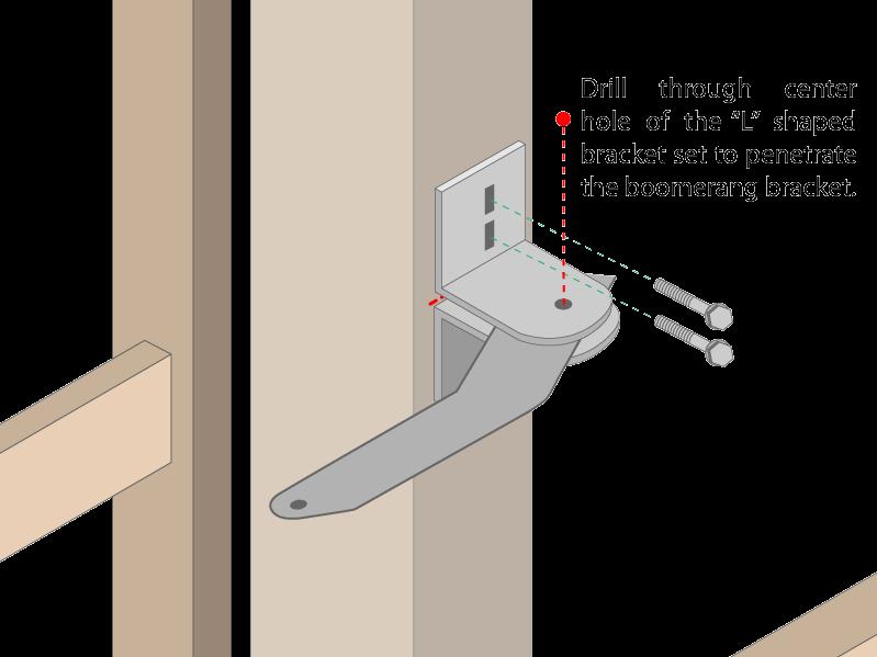
9 4. Place one of the L shape brackets with the top lined up with the line drawn on the post in step 3. The side of post the bracket will be on was determined in step 2 when lining up the boomerang bracket. Drill two holes using a 3/8 drill bit and attach with the appropriate 3/8 bolt, washer, lock washer and nut. 4. Place one of the L shape brackets with the top lined up with the line drawn on the post in step 3. The side of post the bracket will be on was determined in step 2 when lining up the boomerang bracket. Drill two holes using a 3/8 drill bit and attach with the appropriate 3/8 bolt, washer, lock washer and nut. 5. Place the trimmed boomerang bracket on top of the L shape bracket mounted in step 4. Then place firmly atop the boomerang bracket the second L shape bracket. Mount the second L shape bracket using 3/8 holes and hardware. After mounting of the second L shape, pivot the sandwiched boomerang bracket to match the setback and drill the boomerang bracket through hole of the L shape using a 3/8 drill bit. 6. Insert the 3/8 bolt and secure the boomerang in place after checking once again it is positioned to match the setback using a lock washer, washer, and nut. Locate a part of the L shape brackets that when drilled through will also pass through the boomerang bracket. Drill using a 5/16 bit and secure using the 5/16 bolt, lock washer, washer and nut. 5. Place the trimmed boomerang bracket on top of the L shape bracket mounted in step 4. Then place firmly atop the boomerang bracket the second L shape bracket. Mount the second L shape bracket using 3/8 holes and hardware. After mounting of the second L shape, pivot the sandwiched boomerang bracket to match the setback and drill the boomerang bracket through hole of the L shape using a 3/8 drill bit. 6. Insert the 3/8 bolt and secure the boomerang in place after checking once again it is positioned to match the setback using a lock washer, washer, and nut. Locate a part of the L shape brackets that when drilled through will also pass through the boomerang bracket. Drill using a 5/16 bit and secure using the 5/16 bolt, lock washer, washer and nut. 9


10 7. With the gate in the OPEN position, attach the gate opener to the post bracket assembly and gate bracket. Swing the arm over to the gate and mark the holes. For the gate bracket. NEVER turn the shaft of the gate opener, it is located in the correct open retracted position from factory. 8. Prior to drilling the holes for your gate bracket, place a level on the shaft of the gate opener to check levelness. Drill the two oblong holes with a 3/8 drill bit and secure using 3/8 carriage bolts, lock washers, washers and nuts. Recheck the open position, at this point it is adjustable by the length of the oblong holes. After the location is confirmed drill a 1/4 hole through the center hole of the gate bracket to lock its horizontal position. Secure with a 1/4 hex bolt, lock washer, washer, and nut. 7. With the gate in the CLOSED position, attach the gate opener to the post bracket assembly and gate bracket. Swing the arm over to the gate and mark the holes. For the gate bracket. NEVER turn the shaft of the gate opener, it is located in the correct closed retracted position from factory. 8. Prior to drilling the holes for your gate bracket, place a level on the shaft of the gate opener to check levelness. Drill the two oblong holes with a 3/8 drill bit and secure using 3/8 carriage bolts, lock washers, washers and nuts. Recheck the open position, at this point it is adjustable by the length of the oblong holes. After the location is confirmed drill a 1/4 hole through the center hole of the gate bracket to lock its horizontal position. Secure with a 1/4 hex bolt, lock washer, washer, and nut. 9. Secure the arm in place with a cotter pin on the gate side and a C clip on the post side. 9. Secure the arm in place with a cotter pin on the gate side and a C clip on the post side. 10
 and at least 3 feet from ground level.")
 1-1/4 and 4) 7/8 knockouts in the bottom. Remove the needed knockouts using a screwdriver and pliers. Push the screwdriver through an edge, grab and twist using the pliers.")


. - 1 ¾ Tee - 1 ¾ Plug. - 1 ¾ male galvanized pipe X female hose fitting (usually in Brass). - Large hammer.")

11 Mount the control box and run wires from the gate opener(s) into the box 10. Find a location for the control box within 5 feet of the operator arm (or primary operator arm for a dual gate opener) and at least 3 feet from ground level. Level the box on the post, column or fence and mount using 4) #10 self drilling screws or other hardware appropriate for the surface the control box is being mounted to. 11. The box has 2) 1-1/4 and 4) 7/8 knockouts in the bottom. Remove the needed knockouts using a screwdriver and pliers. Push the screwdriver through an edge, grab and twist using the pliers. Insert a water tight connector. Run the wire from the gate operator through the connector to the location of the control board. Connections for a dual gate Mount the dual connection box on the secondary side of the gate on the post. Feed the secondary wire into the box and the secondary motor wire into the box. Place the connector strip in the box and match color to color on the connection strip. TIP: If junction box is located in a high moisture area, apply petroleum jelly on to the terminal block to protect from moisture. Running wire under the driveway Needed: - Narrow shovel. - ¾ water pipe no more that 5 in length (you would need a total number of pipes that would equal your driveway width plus 1 ). - ¾ electric rigid pipe couplings (one for each joint in the water pipe). - 1 ¾ Tee - 1 ¾ Plug. - 1 ¾ male galvanized pipe X female hose fitting (usually in Brass). - Large hammer. All the above items could be found in a local home supply store. Dig a trench perpendicular to the driveway approximately 6 to 8 inches deep and 6 long Hook up a typical garden hose assembled to the first length of pipe as shown Turn on water and push the pipe under the driveway, matching the pitch of the driveway. If you hit a rock use the hammer to force the pipe past the rock. Attach additional pieces of pipe to the initial length by removing the tee and using the coupling to add the additional length of pipe, reassemble the tee and repeat the above steps until only 6 inches of pipe is sticking out from under the driveway. On the opposite side of the driveway look for a wet spot or water bubbling up, dig to find the end of the pipe. This process is good for driveways up to 24 in width. 11


12 Wire the Operator Arm(s) to the Control Board The green terminal strips on the control board are easily removed for wiring. Simply pull straight out on the terminal strip to remove it from the board. It will slide right off. Slide it back on when you are finished with your wiring connections. Single Gate Dual Gate 12. Connect the wires from the operator arm to the control board as seen above. 12. Connect the wires from the operator arms to the control board as seen above. 13. If not using a photo eye leave the factory installed jumper between the terminals PHOTO and GND installed. If using a photo eye it is best to leave the jumper installed until after programming is finished and accessories are being installed. 12
 OFF: Single gate opener (1 motor) DP 3 ON: Gate lock terminals active OFF: Gate lock terminals inactive Power Connection 15.")


13 14. Set dip switches into the correct position for your gate opener: DP 1 ON: Auto-Close on (the gate will reclose from the open position after a time set in the programming section) OFF: Auto-Close off DP 2 ON: Dual gate opener (2 motors) OFF: Single gate opener (1 motor) DP 3 ON: Gate lock terminals active OFF: Gate lock terminals inactive Power Connection 15. Crimp the battery connectors (not included) to the battery wire. The only power connected to the Estate Swing E-S Allegiant control board will be the battery* (not included). Important: Please respect polarity when attaching the battery terminals. Do not cross wires. Connect the factory installed spade connectors to the control board as seen in diagram below. *A Group Size 24 Deep Cycle Marine battery is required for this system. The battery size may be increased for power storage. Note: Deep cycle marine batteries are available at auto part stores, home stores, and battery stores. If the battery sitting in the bottom of the control box no longer leaves room for wires to be fed into the box, set the battery atop the battery lifts. 16. Connect the charging controls to the battery. See below for connection details Transformer / Charge board: Transformer can be located up to 200 feet from the battery using 16 gauge 2 conductor wire. Connect positive and negative of transformer to positive and negative of solar terminals of charge board. Connect positive and negative of battery to positive and negative battery terminals of charge board. Respect polarity. Out terminals are not used. Charge board can be placed on top of battery. Transformer must be in an indoor location or under a plug cover. 20 Watt or Higher / Charge board: Connect positive and negative of battery to positive and negative battery terminals of charge board. Respect polarity. Charge Board Control Board 20 Watt or Control Board 5 Watt or 5 and 10 Watt solar panel Connect the positive and negative of the solar panel directly to the battery respecting polarity. Solar panels can be placed up to 200 feet away using 16 gauge 2 conductor wire. Solar panels must be in full sun and directed south. 10 Watt 13


14 Programming Piston Extended Position For SINGLE GATE Pull to Open: 17. Remove sticker on end of the arm. Press/release the SET button. P1 will show on the display. Press add to select PC for push to close. 18. Press/release the SET button repeatedly until display returns to dots. For SINGLE GATE Push to Open: 17. Remove sticker on end of the arm. Press/release the SET button. P1 will show on the display. Press add to select PO for push to open. 18. Press/release the SET button repeatedly until display returns to dots. 19. Press/hold the SET button until U1 is on the display. 19. Press/hold the SET button until U1 is on the display. 20. The gate opener is in programming mode. Press/hold DEC button. The piston will slowly extend as you hold DEC button. Release the DEC button when the gate reaches the closed position. If DEC button is released it can be pressed again to close further. If gate is over closed press/hold ADD button to retract piston. 21. When closed position is correct press/ release the set button. Then press/release ADD button. The gate will slowly open to the full open position. Once open it will automatically close at full speed. Once closed, the programming is complete. 20. The gate opener is in programming mode. Press/hold DEC button. The piston will slowly extend as you hold DEC button. Release the DEC button when the gate reaches the open position. If DEC button is released it can be pressed again to open further. If gate is past open press/hold ADD button to retract piston. 21. When open position is correct press/ release the set button. Then press/release ADD button. The gate will slowly open to the full closed position. Once closed it will automatically open at full speed. Once open, the programming is complete. *Note: If reprogramming rather than programming for the first time read programming note in trouble shooting section first. 14


15 Programming Piston Extended Position For DUAL GATE Pull to Open: 17. Remove sticker on end of the arm. Press/release the SET button. P1 will show on the display. Press Add to select PC for push to close. 18. Press/release the SET button repeatedly until display returns to dots. 19. Press/hold the SET button until U1 is on the display. 20. The gate opener is in programming mode. Press/hold DEC button. The secondary piston will slowly extend as you hold DEC button. Release the DEC button when the gate reaches the closed position. If DEC button is released it can be pressed again to close further. If gate is over closed press/hold ADD button to retract piston. Press/release SET button and U2 will show on display. Repeat step 20 and secondary piston will close 21. When closed position is correct press/release the set button. Then press/ release ADD button. The gates will slowly open to the full open position. Once open it will automatically close at full speed. Once closed, the For DUAL GATE Push to Open: 17. Remove sticker on end of the arm. Press/release the SET button. P1 will show on the display. Press Add to select PO for push to open. 18. Press/release the SET button repeatedly until display returns to dots. 19. Press/hold the SET button until U1 is on the display. 20. The gate opener is in programming mode. Press/hold DEC button. The secondary piston will slowly extend as you hold DEC button. Release the DEC button when the gate reaches the open position. If DEC button is released it can be pressed again to open further. If gate is past open press/hold ADD button to retract piston. Press/release SET button and U2 will show on display. Repeat step 20 and secondary piston will close 21. When open position is correct press/ release the set button. Then press/release ADD button. The gates will slowly close to the full open position. Once closed it will automatically open at full speed. Once open, the programming is complete. *Note: If reprogramming rather than programming for the first time read programming note in trouble shooting section first. 15


16 22. Set the parameters to match the needed settings. Press/release the SET button to access the parameters. Press/release the ADD or DEC buttons to review or change the individual parameter settings. Press/release the SET button to move to the next parameter. 23. Program remote transmitters to the board. Press/ release the learn button. Learn LED will illuminate. P1 is setting pull or push to open. P0 = Push to open, PC = Pull to open P2 is setting primary leaf force. The lower the number the easier the gate will reverse directions when it meets resistance. This number may have to be changed to a higher setting if your gate is obstructing unexpectedly. The number should be set to the highest number during initial setup and reduced to the point of reliable operation that takes into account change in gate resistance through out the year. The options are P3 is setting secondary leaf force. Note: this parameter will only show if Dip Switch 2 is UP. The lower the number the easier the gate will reverse directions when it meets resistance. This number may have to be changed to a higher setting if your gate is obstructing unexpectedly. The number should be set to the highest number during initial setup and reduced to the point of reliable operation that takes into account change in gate resistance through out the year. The options are P4 is setting a delay between leafs if you have overlapping gates or a gate lock. Note: this parameter will only display if DIP Switch 2 is UP. The motor wired into the primary terminals (1) open first if there is a delay and closes second. It is recommended to have a delay of 3 seconds to avoid any jamming issues between leafs. P5 is release time for the gate lock. Note: this parameter will only display if DIP Switch 3 is UP and professional board is installed. This option determines the length of time 12VDC will be sent out of terminals E_LOCK. The options are 1-4 seconds. P6 is delay for automatic re-close from the open position. Note: this parameter will only display if DIP Switch 1 is UP. This option needs to be turned on using the dip switch on the board. The options are 0-99 seconds. 24. Press/hold a button on a remote transmitter until the learn LED flashes. Repeat step 24 with other buttons on the remote or buttons on other remotes. NOTES ABOUT REMOTES: You can program up to 400 codes into the receiver. This could mean 1 button on 400 different remotes or this could mean all 4 buttons on 100 remotes or anything in between. Some choose to program all 4 buttons to a single receiver if they are not using multiple gates to eliminate pressing the incorrect button on the remote. To do so follow the programming above with each button of the remote. You can erase all programmed codes by holding Learn 1 until the Learn LED comes ON and then turns OFF. 25. The gate opener is now installed and operational via remote transmitter. Please review the troubleshooting / control board overview section following this page for more information on your gate opener. Also review this area for more information on optional accessory installation /16 16
17 Allegaint troubleshooting guide Symptom troubleshooting Gate is moving slowly during operation. Check the battery voltage at rest. Check the battery voltage under load. Battery Voltage should be between volts at rest. The battery voltage under load should not drop more than 1 volt. If the voltage checks out good then check the LS parameter, the speed may be set too low. If a transformer or solar panel and charge controller are being used to trickle charge the battery. check output voltage of the transformer or solar panel. Solar panel output voltage.will vary with the amount of sunlight. Make sure the solar panel is in direct sunlight for at least minutes before testing the voltage.the solar panel should be putting out 12-18VDC in direct sunlight. The output voltage of the transformer will be anywhere from 18-21VAC or 18-21VDC *Depending one what transformer is being used* 17
18 The Estate swing 12V charge controller output voltage will be Volts. Control board is displaying * PH* Safety jumper is not present between PHOTO and GND terminals, place safety jumper in GND and PHOTO on the photocell terminal block. If a safety device is being used instead of a safety jumper. Check the connections of the safety device make sure the metal tab in the terminal is not crimped on the insulation of the wire. If all connections are good check the alignment of the photo eye if misaligned realign the photo eye. Gate operator stops then reverses but does not return to fully closed or open position. Check for any obstructions in the path of the gate. Check the P2 (Force) setting, if a single gate application is being used. Check both the P2 and P3 setting if a dual gate application is being used. The setting may be too low to operate the gate. Increase the setting in small increments if lower than 25. * refer to page 15 for description of parameter* If the P2 or P3 (force) setting is higher than 25 Then check the mounting brackets * refer to page 6 of the manual* to confirm that the brackets are mounted according to your degree of opening, could be 90, 100, or 110 degrees. Gate should be level. 18
19 Any gate over a 100 pounds should have greased ball bearing hinges. The gate should have 50% wind capacity if not obstruction can occur. Gate operator stops moving during programming Disconnect the power and confirm that the 1st and 3rd dip switch are in the down (off) position If using a single application confirm that the 2nd dip switch is in the down (off) position. If using a dual application confirm that the 2nd dip switch is in the up (on) position Gate operator only moves in one direction Check the 3.5 Amp fuse for continuity, it is located on the left hand side of the control board. Gate operator opens randomly Check for any loose connections from any accessories being used ( exit wand, external receiver, push button, hardwired keypads ext..) If all connections are good then start to disconnect any accessories one by until the issue stops. If the issue stops then the last accessory disconnected will mostly likely be causing the issue. 19


20 Electrical multi-meter Items needed for troubleshooting If you call in for technical support or warranty support: Before any control board or motor will be permitted to be sent in for testing or warranty you will be required to digital photos to the technician. 20
21 21
EstateSwing.com. Plug-in Option. E-S 1000H Series INSTRUCTION MANUAL
 EstateSwing.com Plug-in Option E-S 1000H Series INSTRUCTION MANUAL Estate Swing Summary of Functions The Estate Swing is only to be used for vehicular swing gates in a Class I setting. Class I: A vehicular
Buffalo America C Column Mountable Gate Opener WARNING
 Column Mountable Gate Opener WARNING Read all instructions before beginning installation or use of this gate opener. This operator exerts a high level of force. Exercise caution at all times and stay clear
EstateSwing.com. Plug-in Option. E-S 1000H Series INSTRUCTION MANUAL
 EstateSwing.com Plug-in Option E-S 1000H Series INSTRUCTION MANUAL Estate Swing Summary of Functions The Estate Swing is only to be used for vehicular swing gates in a Class I setting. Class I: A vehicular
Instruction Manual for the. E-SL 450 Series
 Instruction Manual for the E-SL 450 Series Estate Slide Summary of Functions The Estate Slide is only to be used for vehicular Slide gates in a Class I setting. Class I: A vehicular gate opener (or system)
Instruction Manual for the. E-SC 1600 / E-SC 1602 Series
 Instruction Manual for the E-SC 1600 / E-SC 1602 Series WARNING - Read all instructions before beginning installation or use of this gate opener. This operator exerts a high level of force. Exercise caution
E-SL 450BD Series INSTRUCTION MANUAL WARNING USER DRIVEN MANUAL*
 USER DRIVEN MANUAL* Any feedback, changes, or advice we are glad to hear it. Please contact us at support@estateswing.com WARNING Read all instructions before beginning installation or use of this gate
Installing the gate post bracket with the cardboard arm template
 ......... Installing the gate post bracket with the cardboard arm template... Installing gate posts brackets and arms for Push-to-Open or Pull-to-Open gates... Connection of Power Source 240Vac or Solar...
Installing the gate post bracket with the cardboard arm template
 ......... Installing the gate post bracket with the cardboard arm template... Installing gate posts brackets and arms for Push-to-Open or Pull-to-Open gates... Connection of Power Source 240Vac or Solar...
Installation Manual for Heavy Duty Carriage Door Opener
 Installation Manual for Heavy Duty Carriage Door Opener (Directive 89/392/EEC, Annex II, Part B) CE DECLARATION OF CONFORMITY OF MACHINES Declares that: Estate Swing (USA) mod operator Is built to be integrated
AUTOMATIC GATE OPENER
 AUTOMATIC GATE OPENER INSTALLATION MANUAL Model G750 For Single Gates AUTOMATIC GATE OPENER Installation Manual GATE OPENER CLASS CATEGORIES* The Zareba Automatic Gate Opener is intended for use with vehicular
AUTOMATIC GATE OPENER
 AUTOMATIC GATE OPENER Part # 7001282.001 Rev.A INSTALLATION MANUAL Model G752 For Double Gates AUTOMATIC GATE OPENER Installation Manual GATE OPENER CLASS CATEGORIES* The Zareba Automatic Gate Opener is
JEEVES. JEEVES Installation Manual. Installation Manual The Easiest Do-It-Yourself Dumbwaiter on the Market
 1 888-323-8755 www.nwlifts.com JEEVES Installation Manual The Easiest Do-It-Yourself Dumbwaiter on the Market This manual will cover the installation procedure step-by-step. The installation of this dumbwaiter
AgriWheel Single Gate Kit Low Voltage & Solar. Installation & Operating Instructions
 AgriWheel Single Gate Kit Low Voltage & Solar Installation & Operating Instructions Thank you for purchasing you AgriWheel system. Please remove the lids from both the machine and control box and remove
Model 1550 Single Swing Gate Model 1650 Dual Swing Gate
 Gate Operators, Inc. Model 1550 Single Swing Gate Model 1650 Dual Swing Gate Swing Gate Operator CONTENTS Safety Precautions... 2 Applications... 3 Pre-Installation Checklist... 4 Parts Identification...
Instruction Manual for the
 Instruction Manual for the E-S 1600 / E-S 1602 Series Manufactured by (Directive 89/392/EEC, Annex II, Part B) CE DECLARATION OF CONFORMITY OF MACHINES Manufacturer: FAAC S.p.A. Address: Via Benini, 1
APOLLO Gate Operators, Inc.
 APOLLO Gate Operators, Inc. Model 3500ETL/3600ETL Commercial Swing Gate Operator INSTALLATION MANUAL 01/08 CONTENTS IMPORTANT SAFETY INSTRUCTIONS. 3 Applications... 4 Pre-Installation Checklist... 5 Parts
GENERAL SAFETY... 3 PARTS LIST...
 Rev 17a 1 GENERAL SAFETY... 3 PARTS LIST... 4 GTR100... 4 GTR058... 5 TECHNICAL SPECIFICATIONS... 6 FEATURES:... 6 QUICK INSTALLATION GUIDE... 7 GATE ARM INSTALLATION... 8 BEFORE YOU START... 8 INSTALLATION
MNBRATKIT MidNite Brat Solar Charging Kit
 1 pc MNBRAT 20/30-amp PWM Charge Controller 1 pc MNBIGBABY Breaker Box 3 pcs 1-10A 1-20A 1-30A MNEPV- PV, Battery and Load Breakers 2 pcs 2 pcs 9-161-1 Strain Relief 9-162-1 Lock Nut 2-4 Hole Strain Reliefs
Gate Operators, Inc. Model 7100UL Residential & Medium Duty Commercial Slide Gate Operator INSTALLATION MANUAL
 Gate Operators, Inc. Model 7100UL Residential & Medium Duty Commercial Slide Gate Operator INSTALLATION MANUAL 10-04-00 CONTENTS Safety Precautions... 2 Applications... 3 Pre-Installation Checklist...
DS1U GATE OPENER INSTALLATION AND OWNERS MANUAL
 DS1U GATE OPENER INSTALLATION AND OWNERS MANUAL A 12 V BATTERY IS REQUIRED TO OPERATE OPENER AND IS NOT INCLUDED! YOU MUST PURCHASE A 12 V AUTOMOTIVE OR MARINE BATTERY BEFORE INSTALLING OR PURCHASE OUR
APOLLO Gate Operators, Inc.
 APOLLO Gate Operators, Inc. Model BA12 12 VOLT DC BARRIER ARM OPERATOR INSTALLATION MANUAL 0707 CONTENTS IMPORTANT SAFETY INSTRUCTIONS... 3 Applications... 4 Pre-Installation Checklist... 5 Operator Installation...
Table of Contents. Safety Instructions page 2
 Table of Contents Safety Instructions -------------------------------------------------------------------- page 2 Caution Signs and Labels ----------------------------------------------------------- page
Installation Manual for the
 Installation Manual for the 352 E-Z GATE OPENER UL325 SERIES WARNING! This equipment is similar to other gate or door equipment and meets or exceeds Underwriters Laboratory Standard 325 (UL 325). However,
Installation Manual CS9100-LED. Professional Series Landscape Lighting System
 Installation Manual CS9100-LED Professional Series Landscape Lighting System LED Landscape Lighting System pg. 1 READ THESE INSTRUCTIONS ENTIRELY BEFORE BEGINNING INSTALLATION! Congratulations on your
Installation Manual CS9300-LED. Professional Series Landscape Lighting System
 Installation Manual CS9300-LED Professional Series Landscape Lighting System CS9300 Professional Series LED Landscape Lighting System pg. 1 READ THESE INSTRUCTIONS ENTIRELY BEFORE BEGINNING INSTALLATION!
Installation Manual for the MM362-D AUTOMATIC GATE OPENER WARNING!
 Installation Manual for the MM362-D AUTOMATIC GATE OPENER WARNING! This equipment is similar to other gate or door equipment and meets or exceeds Underwriters Laboratory Standard 325 (UL 325). However,
Installation Manual. Post Bracket Assembly. Gate Bracket. 12 Volt automotive or marine type battery in weather proof housing (not included).
.") Installation Manual MM360 Receiver Gate Swings Evenly and Freely Hung Firmly and Plumb Warning Sign Post Bracket Assembly Single Gate Opener 120 Volt indoor Transformer (surge protector not supplied) Gate
Installation Manual MM360 Receiver Gate Swings Evenly and Freely Hung Firmly and Plumb Warning Sign Post Bracket Assembly Single Gate Opener 120 Volt indoor Transformer (surge protector not supplied) Gate
INSTALLATION M ANUAL
 INSTALLATION MANUAL Table of Contents UL Listings Installing the Warning Sign / Precautions Methods of Installation / Compact Installation Mounting the Secondary Entrapment / Welding Gate Arn Mounting
Instruction Manual for the. E-SL 1800 Series. Warning! Read all instructions before beginning installation or use of this door opener.
 Instruction Manual for the E-SL 1800 Series Warning! Read all instructions before beginning installation or use of this door opener. This operator exerts a high level of force. Exercise caution at all
Table of Contents. General Safety Preparation for Installation Parts List Optional Accessories Part List... 5
 REV 12a Table of Contents General Safety....... 2 Preparation for Installation....... 3 Parts List....... 4 Optional Accessories Part List...... 5 Technical Specifications & Feature...... 5 Installation
Installation Instructions
 Instructions Created by an: DIY Underhood LED Lighting Kit (SKU# DIY-E-UHLK) Installation Instructions NOTICE: This Under Hood Light Kit was installed on a 2002 Toyota Tacoma. However, these instructions
Installation Manual for the. Automatic Gate Operator
 Installation Manual for the Automatic Gate Operator Series + L I S T E D 75 for Vehicular Swing Gates WARNING! READ ALL INSTRUCTIONS CAREFULLY AND COMPLETELY before attempting to install and use this automatic
Product Manual Manuel du Produit Manual del Producto
 L Product Manual Manuel du Produit Manual del Producto SOLW2 / SOLW6 / SOLWLR / SOLWH06 / SOLWH12 / SOLWSL2 / SOL30X4 / SOLW88X10 / SOLTRANS88 1.330.274.8317 www.atlanticwatergardens.com Introduction Thank
A B C D E F. Tools Required (supplied by others)
") Page 1 of 17 Parts List Below Deck Automatic Retractable Security Cover Kit (1) Tube End Bearing Plate (A) (1) Rope Reel and Cover Drum Motor Assembly (B) (1) Cover Drum (1) Pulley Support Channel (2)
Page 1 of 17 Parts List Below Deck Automatic Retractable Security Cover Kit (1) Tube End Bearing Plate (A) (1) Rope Reel and Cover Drum Motor Assembly (B) (1) Cover Drum (1) Pulley Support Channel (2)
Installation and Maintenance Manual
 Installation and Maintenance Manual Swing Gate Operator Model HL410-21 & HL410L-21 2 Contents Contents Parts & Components 3 Specifications & Capacities 4 Safety Information 6 Installer 6 End User 7 General
Featuring. Manufactured by
 Featuring Manufactured by (Directive 89/392/EEC, Annex II, Part B) CE DECLARATION OF CONFORMITY OF MACHINES Manufacturer: FAAC S.p.A. Address: Via Benini, 1 40069 Zola Predosa Bologna Italy Declares that:
Midnite Kid Basic Solar Charging Kit
 What does my kit come with? 1pc MNKID-B 30-amp MPPT Charge Controller 1pc MNBIGBABY- 4 position breaker box 2 pcs MNEPV30- PV and battery breaker 1 pc GFP63 Ground Fault Protection Breaker 2pcs each Strain
Installation and Set Up Instructions
 SL 2000 DC2 SLIDING GATE MOTOR KIT Solar Powered and 12V Low Voltage Installation and Set Up Instructions Unit 27 / 49 Corporate Boulevard Bayswater Vic 3153 Phone 1800 111 930 Email info@gforceautogates.com.au
Installation Manual. Gate Swings Evenly and Freely Hung Firmly and Plumb Warning Sign. Horizontal Support
 Installation Manual MM362 Control Box Gate Swings Evenly and Freely Hung Firmly and Plumb Warning Sign 120 Volt indoor Transformer Post Bracket First Gate Opener Gate Bracket Gate Bracket Second Gate Opener
Installation Manual for the. Automatic Gate Opener System for Single Swing Gates Only
 Installation Manual for the 250 E-Z GATE OPENER UL325 SERIES 1-800-543-GATE (4283) www.mightymule.com Automatic Gate Opener System for Single Swing Gates Only WARNING! This equipment is similar to other
Installation and Service Manual
 RESIDENTIAL PLATFORM LIFTS RPL400 / RPL600 Installation and Service Manual WARNING! STRICT ADHERENCE TO THESE INSTALLATION INSTRUCTIONS IS REQUIRED to promote the safety of those installing this product,
Installation/Owners Manual
 Installation/Owners Manual PATRIOT I Single Swing Gate Operator PATRIOT II Dual Swing Gate Operator Heavy Duty Battery Powered Solar or AC Charged WARNING TO REDUCE THE RISK OF INJURY OR DEATH 1. READ
Installation Manual FM402 WARNING!
 Installation Manual FM402 WARNING! This equipment is similar to other gate or door equipment and meets or exceeds Underwriters Laboratory Standard 325 (UL 325). However, gate equipment has hazards associated
Instructions for MB832 Manual Barrier Ver0614
 Instructions for MB832 Manual Barrier Ver0614 Read all the instructions before starting It is recommended that Locktite Blue brand thread sealant be used for all arm and pivot bolts as added protection
HYPPOETL HYPPO DUALETL 12 VOLT DC Swing Gate Operator
 HYPPOETL HYPPO DUALETL 12 VOLT DC Swing Gate Operator Manufactured by NICE SpA INSTALLATION MANUAL 08/10 CONTENTS IMPORTANT SAFETY INSTRUCTIONS... 3 Applications...... 4 Pre-Installation Checklist... 5
TO AVOID DOING IRREPARABLE DAMAGE TO DRIVE CIRCUITRY NEVER APPLY AC POWER DIRECTLY TO LED LIGHTBOXES!
 INSTALLATION MANUAL TO AVOID DOING IRREPARABLE DAMAGE TO DRIVE CIRCUITRY NEVER APPLY AC POWER DIRECTLY TO LED LIGHTBOXES! 4949 South 110 th Street Greenfield, WI 53228 Phone: (800) 610-6053 Fax: (414)
Automatic Gate Openers Gate Opener Accessories
 Automatic Gate Openers Gate Opener Accessories PRODUCT OFFERINGS Standard Installation Single Gate Operators Dual Gate Operators Accessories Driveway Alarm Frequently Asked Questions 3 4 5 6 10 11 2 www.mightymule.com
Safety Installation Information Single Gate Opener Parts List...4. Dual Gate Opener Parts List...5. Technical Specifications & Features...
 Table of Contents ` Safety Installation Information..... 2-3 Single Gate Opener Parts List.........4 Dual Gate Opener Parts List........5 Technical Specifications & Features...........6-7 Installation
IMPORTANT: Before you install the automatic gate lock be sure your gate is level, moves freely on hinges, and is free from binding and/or dragging.
 Before You Start... IMPORTANT: Before you install the automatic gate lock be sure your gate is level, moves freely on hinges, and is free from binding and/or dragging. For the GTO Automatic Gate Lock work
CE DECLARATION OF CONFORMITY OF MACHINES. Warnings for the installer General safety obligations
 Featuring (Directive 89/392/EEC, Annex II, Part B) CE DECLARATION OF CONFORMITY OF MACHINES Manufacturer: FAAC S.p.A. Address: Via Benini, 1 40069 Zola Predosa Bologna Italy Declares that: Domoswing mod
Installation Manual. CS9300 Professional Series Landscape Lighting System
 Installation Manual CS9300 Professional Series Landscape Lighting System CS9300 Professional Series Landscape Lighting System pg. 1 READ THESE INSTRUCTIONS ENTIRELY BEFORE BEGINNING INSTALLATION! Congratulations
INSTALLATION INSTRUCTIONS
 28 INSTALLATION INSTRUCTIONS SECTION - AIR SPRING SECTION 2 - AIR ACCESSORY 2-5 ! IMPORTANT PLEASE DON T HURT YOURSELF, YOUR KIT OR YOUR VEHICLE. TAKE A MINUTE TO READ THIS IMPORTANT INFORMATION. This
Instruction Manual for the. Heavy Duty Series Carriage Door Instructions. Warning!
 Instruction Manual for the Heavy Duty Series Carriage Door Instructions Warning! Read all instructions before beginning installation or use of this door opener. This operator exerts a high level of force.
Sliding Gate Opener User s Manual
 Gat Model: Sliding Gate Opener User s Manual GA2500 Gate1Access, LLC. www.gate1access.com Email: support@gate1access.com 1 Thank you for purchasing GA2500 gear rack drive sliding gate opener. We are sure
Instruction Manual for the
 Instruction Manual for the Heavy Duty Series Carriage Door Instructions Manufactured by (Directive 89/392/EEC, Annex II, Part B) CE DECLARATION OF CONFORMITY OF MACHINES Manufacturer: FAAC S.p.A. Address:
Motorized Skylight Installation Instructions
 Motorized Skylight Installation Instructions Getting Started A few simple tools are required: - Measuring tape - Power drill, drill bits - Hex head and/or Phillips driver bit - Pencil Additional fasteners
2904 Power Supply Installation Instructions I-EA00041
 FEATURES Controls an opening with electrified locking device and automatic door operator Separate inputs for activation switch on entry and exit sides of opening Separate 24 VDC outputs for fail safe and
ELECTRO-MECH SCOREBOARD CO.
 ELECTRO-MECH SCOREBOARD CO. MM-338 FOOTBALL SCOREBOARD OWNER S HANDBOOK Thank you for choosing an Electro-Mech Scoreboard for your athletic complex. We are confident that your new scoreboard will give
Installation and Set Up Instructions
 Model FG 5-7 / SW 5-7 / DSW 5-7 Swing Gate Motor Kit Solar powered and 12V Low Voltage Installation and Set Up Instructions Unit 27 / 49 Corporate Boulevard Bayswater Vic 3153 Phone 1800 111 930 Email
The USAutomatic Electric Gate Lock Assembly works with most types of gates and mounting applications.
 USAUTOMATIC ELECTRIC GATE LOCK Part Number 070510 Installation Manual The USAutomatic Electric Gate Lock works with an automatic gate operator to securely lock the gate into position without having to
Installation Manual for the
 UL325 SERIES 1-800-543-GATE (4283) www.mightymule.com 1. KEEP CLEAR! Gate may move at any time. 2. Do not allow children to operate gate or play in gate area. 3. This gate is for vehicles only. Pedestrians
Installation Manual for the. Automatic Gate Opener System FOR DUAL SWING GATES
 Installation Manual for the AUTOMATIC GATE OPENER Automatic Gate Opener System FOR DUAL SWING GATES WARNING! READ ALL INSTRUCTIONS CAREFULLY AND COMPLETELY before attempting to install and use this automatic
Installation/Owners Manual
 Installation/Owners Manual Ranger I Single Swing Gate Operator Ranger II Dual Swing Gate Operator Heavy Duty Battery Powered Solar or AC Charged WARNING TO REDUCE THE RISK OF INJURY OR DEATH 1. READ AND
Alliance Towel Dispensing System. Operation Manual
 Alliance Towel Dispensing System Operation Manual Alliance Towel Dispensing System Table of Contents Safety Information... page 2 Mounting Instructions... page 3 Towel Loading Instructions... page 7 Settings...
WARNING. Important Notice
 CAL (Color AquaLuminator ) Light and Return Water Flow for Above Ground Pools Owners Manual IMPORTANT SAFETY INSTRUCTIONS READ AND FOLLOW ALL INSTRUCTIONS SAVE THESE INSTRUCTIONS Table of Contents SECTION
Installation Manual. for installing the GTO/PRO SW-3200XL with the GTO/PRO SW-3000XL in a dual application FOR PROFESSIONAL INSTALLATION ONLY!
 Installation Manual for installing the GTO/PRO SW-3200XL with the GTO/PRO SW-3000XL in a dual application DC-SERIES DC-SERIES FOR PROFESSIAL INSTALLATI LY! WARNING! This equipment is similar to other gate
Detroit Speed, Inc. Electric Headlight Door Kit Corvette P/N: &
 Detroit Speed, Inc. Electric Headlight Door Kit 1968-82 Corvette P/N: 122006 & 122007 The Detroit Speed Inc. Electric Headlight Door Kit replaces the stock vacuum actuated system on all 1968-82 Corvettes.
Actuator Arm and Control Box Mounting
 Actuator Arm and Control Box Mounting To wire this operator and complete the installation, refer to a specific control box Wiring/Owner s manual. 6002 Vehicular Swing Gate Operator 6002-065-Y-1-13 Copyright
SKC400U SLIDING GATE OPENER OWNER S MANUAL
 SKC400U SLIDING GATE OPENER OWNER S MANUAL IMPORTANT SAFTEY INFORMATION Installing the SKC400U Gate Opener requires wiring of standard 110V electrical lines. This should only be performed by a trained
Vehicular Swing Gate Operator. Nice. Titan 912L. The Titan 912L Gate Operator is intended for use with vehicular swing
 Vehicular Swing Gate Operator Nice Gate Operators Titan 912L The Titan 912L Gate Operator is intended for use with vehicular swing gates. The Titan 912L Gate Operator can be used in Class I, Class II and
Installation/Owners Manual PATRIOT RSL Vehicular Slide Gate Operator Heavy Duty Battery Powered Solar or AC Charged
 Installation/Owners Manual PATRIOT RSL Vehicular Slide Gate Operator Heavy Duty Battery Powered Solar or AC Charged WARNING TO REDUCE THE RISK OF INJURY OR DEATH 1. READ AND FOLLOW ALL INSTRUCTIONS 2.
Installation Manual E8-400 E8-500 E Solar or Electric Systems
 Installation Manual E8-400 E8-500 E8-600 Solar or Electric Systems 1 WARNING Important Safety Information Gate equipment has hazards associated with its use and therefore by installing this product the
INSTALLATION MANUAL. Thunderstone Manufacturing LLC 3400 West O Street Lincoln, NE (Fax)
") INSTALLATION MANUAL August 7 th 2018 43 /48 /50 2011 and Older Timpte STD/Split 36 Style Hopper Trailers with Roller Bearing Doors Kit #101533 for 96w & Kit #101534 for 102w Thunderstone Manufacturing
INSTALLATION MANUAL August 7 th 2018 43 /48 /50 2011 and Older Timpte STD/Split 36 Style Hopper Trailers with Roller Bearing Doors Kit #101533 for 96w & Kit #101534 for 102w Thunderstone Manufacturing
Installation and Set Up Instructions
 SL SLIDING GATE MOTOR KIT Solar Powered and 12V Low Voltage Installation and Set Up Instructions Unit 27 / 49 Corporate Boulevard Bayswater Vic 3153 Phone 1800 111 930 Email info@gforceautogates.com.au
ELECTRO-MECH SCOREBOARD CO.
 ELECTRO-MECH SCOREBOARD CO. MP-140 BASEBALL SCOREBOARD OWNER S HANDBOOK Thank you for choosing an Electro-Mech Scoreboard for your athletic complex. We are confident that your new scoreboard will give
DIAMOND. Installation Manual. DUAL Gate Operator System
 Installation Manual DIAMOND DUAL Gate Operator System WARNING! This equipment is similar to other gate or door equipment and meets or exceeds Underwriters Laboratory Standard 325 (UL 325). However, gate
Package Contents. Mounting Hardware
 Securitron Magnalock Corp. www.securitron.com Tel 800.624.5625 techsupport@securitron.com M680BDCX MAGNALOCK SERIES Installation Instructions Table of Contents Specifications 2 Configuring Options 3 Installation
M670/M680BD MAGNALOCK SERIES Installation Instructions
 Securitron www.securitron.com Tel 800.624.5625 techsupport@securitron.com M670/M680BD MAGNALOCK SERIES Installation Instructions Page 1 Rev. D, 12/14 Table of Contents Package Contents... 3 Mounting Hardware...
3 Year SENTRY 300 S / 300 D. Installation/Owners Manual. High Quality Low Voltage Vehicular Swing Gate Opener
 SENTRY 300 S / 300 D High Quality Low Voltage Vehicular Swing Gate Opener Battery Powered Solar or AC Charged Installation/Owners Manual 3 Year Warranty Designed to open all types of gates in all kinds
Installation Manual SINGLE GATE SYSTEM
 -800-543-GATE (483) www.mightymule.com Can Cause Injury or Death Installation Manual E-Z GATE OPENER 500 UL35 SERIES C L I S T E D US E-Z GATE OPENER 500! WARNING MOVING GATE SINGLE GATE SYSTEM! WARNING
INSTALLATION GUIDES OUTDOOR LIVING
 S OUTDOOR LIVING TABLE OF CONTENTS 12 Volt 12 Watt DC Transformer Page 2 12 Volt 50 Watt DC Smart Transformer Page 3 12 Volt 50 Watt Smart Transformer Control Page 4-5 Waterproof Dimmer For 12W Transformer
INDEX. Safety Instructions page 2
 INDEX Safety Instructions ------------------------------------------------------------------------ page 2 Safety Label Diagram --------------------------------------------------------------------- page
INSTALLATION INSTRUCTIONS
 2807 INSTALLATION INSTRUCTIONS SECTION - AIR SPRING SECTION 2 - AIR ACCESSORY -6 ! IMPORTANT PLEASE DON T HURT YOURSELF, YOUR KIT OR YOUR VEHICLE. TAKE A MINUTE TO READ THIS IMPORTANT INFORMATION. This
Combine Cover Manual
 Combine Cover Manual Installation Instructions Page 26 Operating Instructions Page 7 Warranty Page 7 Trouble Shooting Page 8 10 For Big Top Extension Model s: Case I.H. 8010, 8120 Please forward onto Customer
Instructions for 2-row monitoring only
 Installation Instructions for CaseIH cotton picker models: Instructions for 2-row monitoring only CAUTION: Ensure the model numbers shown above correspond to the machine model. If you receive the incorrect
Ram 1500 Crew Cab A Ram 2500/3500 Crew Cab A
 I N S T A L L A T I O N G U I D E APPLICATION AMP Part # Ram 1500 Crew Cab 2013-2015 77138-01A Ram 2500/3500 Crew Cab 2013-2015 77138-01A Note:The application works only on the Crew Cab model Vehicles.
UGP-712 Vehicular swing gate operator
 Vehicular swing gate operator INSTALLATION INSTRUCTION MANUAL PLATINUM ACCESS SYSTEMS Installation Instructions & Safety Information Manual Vehicular Swing Gate Operator Class I, Class II, Class III, and
Installation Manual for the. Automatic Gate Operator
 Installation Manual for the Automatic Gate Operator WARNING! This equipment is similar to other gate or door equipment and meets or exceeds Underwriters Laboratory Standard 325 (UL 325). However, gate
PowerMaster MODEL MBG. Installation Manual U L R UL 325 AND UL 991 LISTED MEDIUM DUTY BARRIER GATE OPERATOR TABLE OF CONTENTS
 PowerMaster TABLE OF CONTENTS MODEL MBG MEDIUM DUTY BARRIER GATE OPERATOR Important Safety Information...... 3 System Designer Safety Instructions.......4 Installer Safety Instructions....... 5 Installation
TMT Boxer 24v slider motor installation notes from EasyGate
 TMT Boxer 24v slider motor installation notes from EasyGate Install Physical Gate Stops Physical Gate Stops MUST be installed at each end of your gate. If the Limit Switch on the boxer motor fails to stop
MODEL MSW Medium Duty Swing Gate Operator
 INSTALLATION AND OWNER S MANUAL MODEL MSW Medium Duty Swing Gate Operator UL 325 and UL 991 Listed 22-1/4 16-1/2 19-1/2 16 20'' LENGTH X 14-3/4'' WIDTH 2 O.D. PIPE (BY OTHERS) Serial #: Date Installed:
Part# JL AIR IT UP 4 Tire On Board Air Delivery System. (Requires External Air Source)
") Part# 18-1819 JL AIR IT UP 4 Tire On Board Air Delivery System (Requires External Air Source) The most up-to-date instructions always visit www.updownair.com www.updownair.com 833-226-4863 I M P O R T
Part# 18-1819 JL AIR IT UP 4 Tire On Board Air Delivery System (Requires External Air Source) The most up-to-date instructions always visit www.updownair.com www.updownair.com 833-226-4863 I M P O R T
Conflicts: Highlander without sunroof
 Toyota Highlander (Sunroof) 2011-8.5 Overhead Video Part Number: 00016-00125; Fit Kit-00016-00125-02 Accessory Code: ED9 Conflicts: Highlander without sunroof Kit Contents: Item # Qty. Component Description
Photoelectric. Sensors Invisible Light Beam Protection Area
 COMMERCIAL PROTECTOR SYSTEM MODELS CPS-U AND CPS-UN4 To prevent possible SERIOUS INJURY or DEATH from a closing gate or door: Entrapment protection devices MUST be installed per the operator owner's manual.
Instruction Manual for the. E-SC 1600 / E-SC 1602 Series. Manufactured by
 Instruction Manual for the E-SC 1600 / E-SC 1602 Series Manufactured by (Directive 89/392/EEC, Annex II, Part B) CE DECLARATION OF CONFORMITY OF MACHINES Manufacturer: FAAC S.p.A. Address: Via Benini,
LA400 & LA400-S O W N E R ' S M A N U A L MEDIUM DUTY SWING GATE OPERATOR. Large Metal Control Box (XLM) Optional 2 YEAR WARRANTY
 Optional 2 YEAR WARRANTY") LA400 & LA400-S MEDIUM DUTY SWING GATE OPERATOR O W N E R ' S M A N U A L Large Metal Control Box (XLM) Optional Serial # Primary Arm Serial # Secondary Arm Serial # Control Box Installation Date The LA400
LA400 & LA400-S MEDIUM DUTY SWING GATE OPERATOR O W N E R ' S M A N U A L Large Metal Control Box (XLM) Optional Serial # Primary Arm Serial # Secondary Arm Serial # Control Box Installation Date The LA400
Model A Turn Signal Kit Installation Guide
 Model A Turn Signal Kit Installation Guide Creative Connections, Inc. Consumer Hot Line: 888-471-LOGO 770-476-7322 In Atlanta, GA http://www.logolites.com P/N: 100-005/K 2008 Creative Connections, Inc.
Easy Cover. Installation Instructions. Attention Dealers: Please give this owners manual to the customer when the product is delivered.
 Serving the Truck & Trailer Industry Since 944 Easy Cover Attention Dealers: Please give this owners manual to the customer when the product is delivered. Call 00-3-94 www.aeroindustries.com Indianapolis,
access
 184 Table of Contents Access Garage door Motors Dexxo Pro 800 RTS... 188 Dexxo Pro 1000 RTS... 189 Dexxo Optimo RTS... 190 Receiver Axroll NS... 191 Freeroll ESE RTS, RTS receiver for roller garage doors...
Part # Galaxie Level 1 Complete Air Suspension System
 350 S. St. Charles St. Jasper, In. 47546 Ph. 812.482.2932 Fax 812.634.6632 www.ridetech.com Part # 12160199 60-64 Galaxie Level 1 Complete Air Suspension System Front Components: 1 12162409 Front RQ Series