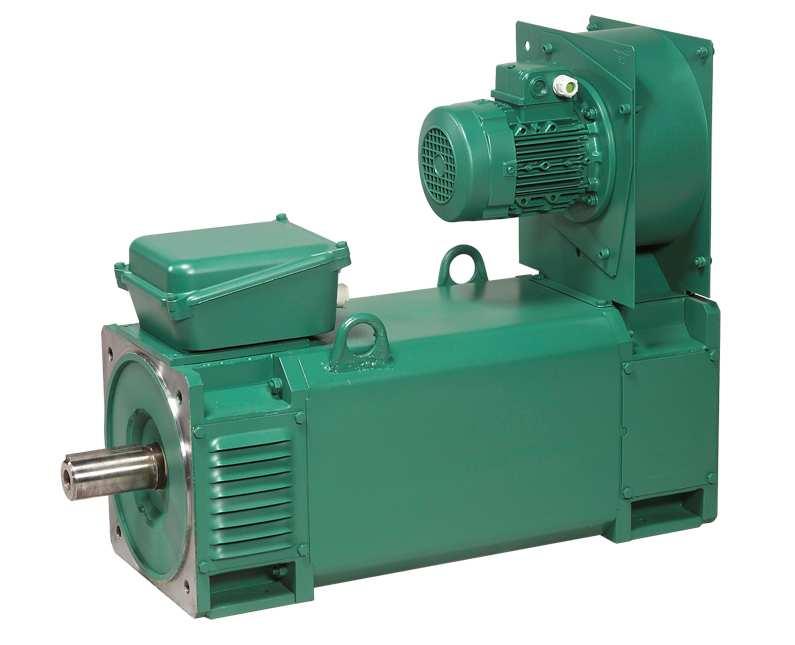
CPLS Drip-proof 3-phase induction motors
|
|
|
- Erin Peters
- 5 years ago
- Views:
Transcription


1 Installation and maintenance

2 IMPORTANT These symbols appear in this document whenever it is important to take special precautions during installation, operation, maintenance or servicing of the motors. It is essential that electric motors are installed by experienced, qualified and authorised personnel. In accordance with the main requirements of EEC Directives, the safety of people, animals and property should be ensured when fitting the motors into machines. Particular attention should be given to equipotential ground or earthing connections. Before touching the motor, you must read the UTE C standard with regard to operator protection as well as any current laws and regulations affecting the safety of personnel. LEROY-SOMER cannot be held responsible for any problems arising from failure to comply with the instructions in this manual. The following preliminary precautions must be taken before working on any stationary device: Mains voltage disconnected and no residual voltage present Careful examination of the causes of the stoppage (jammed transmission - loss of phase - cut-out due to thermal protection - lack of lubrication, etc.) Dear Customer, You have just acquired a LEROY-SOMER motor. This motor benefits from the experience of one of the largest manufacturers in the world, using state-of-the-art technology in automation, specially selected materials and rigorous quality control. As a result, the regulatory authorities have awarded our motor factories the ISO Edition 2000 international certificate. We thank you for making this choice, and would ask you to read the contents of this manual. By observing a few essential rules, you will ensure problem-free operation for many years. LEROY-SOMER NOTE: LEROY-SOMER reserves the right to modify the characteristics of its products at any time in order to incorporate the latest technological developments. The information contained in this document may therefore be changed without notice. Copyright 2005: LEROY-SOMER This document is the property of LEROY-SOMER. It may not be reproduced in any form without prior authorization. All brands and models have been registered and patents applied for. 1
3 SOMMAIRE 1 - RECEIPT MARKING STORAGE ASSEMBLY CHECKING THE INSULATION LOCATION COUPLING ELECTRICAL GUIDELINES MAIN CONNECTIONS STARTUP ROUTINE MAINTENANCE CHECKING THE BEARINGS GREASING PREVENTIVE MAINTENANCE TROUBLESHOOTING GUIDE CORRECTIVE MAINTENANCE GENERAL INFORMATION DISMANTLING THE MOTOR BEFORE REASSEMBLING REASSEMBLY NOMENCLATURE INDEX
 and after a visual check, turn the motor by hand to detect any malfunction. 1.")
4 1 - RECEIPT On receipt of your motor, check that it has not suffered any damage in transit. If there are obvious signs of knocks, contact the carrier (you may able to claim on their insurance) and after a visual check, turn the motor by hand to detect any malfunction. 1.1 Marking As soon as you receive the motor, check that the nameplate on the machine conforms to your order. Nameplate example: Definition of symbols used on nameplates: Legal mark of conformity of product to the requirements of European Directives. 0710M01584: Motor serial number 07 : Year of production 10 : Week of production M01584 : Manufacturing order Mot.3~ : Three-phase A.C. motor : Series 112 : Frame size L : Housing symbol Kg : Weight IP23 : Index of protection cl. F : Insulation class F 40 C : Maximum ambient temperature for operation (IEC ) S : Duty V : Supply voltage Hz : Supply frequency Min-1 : Revolutions per minute (rpm) kw : Rated output power Cos φ : Power factor A Bearings DE NDE : Rated current : Drive end : Non drive end g* : Quantity of grease at each regreasing (in g) h* : Greasing interval (in hours) * Permanently greased bearings if not informed 3

5 1.2 - Storage Prior to commissioning, machines should be stored: - Away from humidity: for relative humidity greater than 90% the machine insulation can drop very quickly and become virtually non-existent at around 100%; check the anti-rust protection on unpainted parts. For very long storage periods the motor can be placed in a sealed package (for example heatshrunk plastic) containing sachets of desiccant. - Protected from frequent significant temperature variations to prevent any condensation during storage. - If the area is subject to vibration, try to reduce the effect of this vibration by placing the motor on a damping support (rubber plate or similar) and turn the rotor a fraction of a turn once a fortnight to prevent the bearing rings from becoming marked. Even if the motor has been stored in the correct conditions, some checks must be carried out before it is started up Greasing Bearings that cannot be regreased Maximum storage: 3 years. After this time, replace the bearings (see section 6.1). Bearings that can be regreased Greases used by LEROY-SOMER 2 - ASSEMBLY Checking the insulation Before starting the motor, it is advisable to check the insulation between the phases and earth, and between phases. This check is essential if the motor has been stored for longer than 6 months or if it has been kept in a damp atmosphere. This measurement must be carried out using a megohmmeter at 500 V DC (do not use a magnetoelectric system). It is better to carry out an initial test at 30 or 50 volts and if the insulation is greater than 1 megohm, carry out a second test at 500 volts for 60 seconds. The insulation value must be at least 10 megohms in cold state. If this value cannot be achieved, or if the motor may have been splashed with water or salt spray, or kept for a long period in a very humid place or if it is covered with condensation, it is advisable to dry the stator for 24 hours in a drying oven at a temperature of between 110 C and 120 C. If it is not possible to place the motor in a drying oven: - Switch on the motor, with the rotor locked, at 3- phase A.C. voltage reduced to approximately 10% of the rated voltage, for 12 hours (use an induction regulator or a reduction transformer with adjustable outlets). - Or supply the 3 phases in series with a D.C. current, with the voltage at 1 to 2% of the rated voltage (use a D.C. generator with independent excitation or batteries for motors of less than 22kW). - NB: The A.C. current must be monitored using a clamp ammeter, and the D.C. current using a shunt ammeter. This current must not exceed 60% of the rated current. It is advisable to place a thermometer on the motor housing: if the temperature exceeds 70 C, reduce the indicated voltage or current by 5% of the original value for every 10 difference. While it is drying, all the motor orifices must be open (terminal box) Warning: If the high voltage test, carried out at the factory before despatch, needs to be repeated, it should be performed at half the standard voltage. ie: 1/2 (2U+1000V). motors are lubricated with EXXON UNIREX N3 grease used as standard. (Grade 3). Prior to commissioning for all motors: Rotate the motor at no load (no mechanical load) for 2 to 5 minutes, checking that there is no abnormal noise. If there is any abnormal noise, see section 5. Before testing at no load and without coupling, secure the key! 4
6 2.2 - Location All motors of the range are IP23. The motor will have to be installed under shelters not to be exposed to bad weather. As standard, the cooling method of these motors is IC06. It means that the cooling fluid is taken from the ambient fluid (air) and rejected in the same way. This fluid circulates thanks to a system independent of the speed of the motor. It is therefore necessary to respect following recommendations: The motor must be installed in a ventilated place, with clearance for the air inlet and outlet. Obstruction (clogging) - even accidental - of the ventilation circuit has an adverse effect on motor operation. It is also necessary to check that the hot air is not being recycled. If it is, pipes must be provided for the intake of cold air and expulsion of hot air, in order to prevent abnormal motor temperature rise. Except contrary mention on the order, the motor is dimensioned for an environment standardized according to EN so as: - altitude : 1000 m or less. - Temperature between +5 and +40 C. The seals should be able to withstand the forces engaged during normal motor operation, as well as a possible over-torque of 2 times the rated torque. For the motor range, standard mounting positions are B3 and B35. Consult the plant for any other mounting position. Motor is fitted with lifting rings mounted diagonally on each flanges. They are designed to lift the motor only and must not be used to lift the motor mounted on the driven equipment. If it is necessary, use a lifting bar system to protect both ventilation and accessories. Note: Never stand on the motor Coupling Preparation Turn the motor by hand before coupling to detect any possible fault due to handling. Remove any protection from the shaft extension. Ensure there is easy access to the terminal box and interventions gates. Positioning The motor must be mounted in the position specified on the order, on a base which is rigid enough to prevent distortion and vibration. Moving the motor For made-to-order motors with roller bearings, in exceptional circumstances when the motor has to be moved after the coupling device has been fitted, the rotor must be immobilised. 5
 must be balanced accordingly.")
 and must be protected against direct contact.")
7 Balancing Rotating machines are balanced in accordance with standard ISO 8821: - Half-key when the shaft extension is marked H: standard - No key when the shaft extension is marked N - Full key when the shaft extension is marked F Thus any coupling element (pulley, coupling sleeve, slipring,etc...) must be balanced accordingly. Motor with 2 shaft extensions: If the second shaft extension is not used, in order to comply with the balancing class, the key or half-key must be fixed firmly in the keyway so that it is not thrown out during rotation (H or F balancing) and must be protected against direct contact. Precautions All measures must be taken to ensure protection against the risks which arise when there are rotating parts (coupling sleeve, pulley, belt etc). Beware of back driving when the motor is switched off. The appropriate precautions must be taken: - On pumps: install a non-return valve. - On mechanical devices: install a backstop or a holding brake, etc Tolerances and adjustments The standard tolerances are applicable to the mechanical characteristics given in our catalogues. They comply fully with the requirements of IEC standard Users must adhere strictly to the instructions provided by the transmission device supplier. - Avoid impacts, which could damage the bearings. Use a spanner and grease the tapped hole of the shaft extension with a special lubricant (e.g. molykote grease) to make it easier to fit the coupling. The hub of the transmission device must be: - Fully in contact with the shoulder of the shaft. - Longer than the shaft extension (2 to 3 mm) so that it can be tightened using a screw and washer. If it is not, a spacer ring must be inserted without cutting the key (if this ring is large, it must be balanced). If there is a second shaft extension, it must only be used for direct coupling and the same recommendations must be followed. Warning: If the 2nd shaft extension is smaller than the main one, do not exceed half the rated torque. Inertia flywheels must not be mounted directly onto the shaft extension, but installed between end shields and connected by a coupling sleeve. Direct connection onto the machine When mounted directly on the motor shaft extension of the moving device (pump or fan turbine), check that this device is perfectly balanced and that the radial force or the axial thrust are within the limits indicated in technical catalogue. Direct connection using a coupling sleeve Selection of the coupling sleeve should take account of the rated torque to be transmitted and the safety factor dependent on the starting conditions for the electric motor. The machines must be carefully aligned, so that any lack of concentricity and parallelism in the two coupling halves is compatible with the recommendations of the coupling sleeve manufacturer. Both coupling halves should be provisionally assembled to assist moving them in relation to one another. Adjust the parallel plane of both shafts using a gauge. Measure the distance between the two coupling surfaces at one point on the circumference. Rotate them 90, 180 and 270 in relation to this initial position, and measure each time. The difference between the two extremes of the value "x" must not exceed 0.05 mm for standard coupling To perfect this adjustment and at the same time check the concentricity of the two shafts, mount 2 gauges, as shown in the diagram, and slowly turn both shafts. 6

8 The deviations registered by either shaft will indicate the need for either an axial or radial adjustment if the deviation exceeds 0.05 mm. Direct connection using a rigid coupling sleeve Both shafts must be aligned so as to adhere to the tolerances of the coupling sleeve manufacturer. Maintain the minimum distance between the shaft extensions to allow for expansion of the motor shaft. If this is not possible, consult LEROY-SOMER. Transmission via belt pulleys The user can choose the diameter of the pulleys. Cast iron pulleys with a diameter over 315 are not recommended for rotation speeds of 3000 rpm and more. Flat belts cannot be used for rotation speeds of 3000 rpm and more. Positioning the belts So that the belts can be correctly positioned, allow for possible adjustment of approximately 3% with respect to the calculated distance E. Force must never be used when fitting the belts. For notched belts, position the notches in the pulley grooves. Aligning the pulleys Φ (mm) A (mm) < Check that the motor shaft is completely parallel and aligned with that of the receiving pulley. Adjusting the tension of the belts Adjusting the tension of the belts must be carried out very carefully in line with the recommendations of the belt supplier. Reminder: - Tension too great = unnecessary force on the end shields which could lead to premature wear of the bearing unit (end shield-bearings) and eventually break the shaft. - Tension too weak = vibration (wearing of the bearing unit) Electrical guidelines Electric motors are industrial products. They must therefore be installed by qualified and experienced personnel. The safety of people, animals and property must be ensured when fitting or building the motors into a machine: please refer to current standards. motors range is designed to be inverter fed. For an optimum and safe functioning, respect the starting-up and protection procedures described in the inverter user guide. Earthing It is essential to earth the motor in order to protect workers. Conform to the current standards and legislation when connecting the earth wires. Built-in thermal protection The motors can be equipped with optional heat sensors; these sensors can be used to monitor temperature rises at "hot spots" in order to detect an overload or faulty cooling (or at strategic points) and thus safeguard the installation. It must be emphasized that these sensors cannot be used to carry out direct adjustments to the motor operating cycle Built-in direct thermal protection For low rated currents, bimetallic strip-type protection may be used. The line current passes through the strip, which shuts down or restores the supply circuit as necessary. The design of this type of protection allows for manual or automatic reset. 7
9 - NRT: nominal running temperature - The NRTs are chosen according to the position of the sensor in the motor and the temperature rise class. - PTO or PTF, in the control circuits - PTC, with relay, in the control circuits - PT 100 or Thermocouples, with reading equipment or recorder, in the control board of the installation for continuous surveillance. Alarm and Safety All protective equipment may be backed up by another type of protection (with a different NRT). The first device will then act as an alarm (light or sound signals given without shutting down the power circuits), and the second device will be the safety system (shutting down the power circuits). Protection against condensation: Space heaters Identification: 1 red label A glass fibre flexible resistor is fixed on 1 or 2 coil end turns. This resistor heats the machines when stopped and thus prevents condensation inside the machines. Power supply: 230V single-phase unless otherwise specified by the customer. 8
10 3-phase forced ventilation wiring The forced ventilation motor must be earthed. The earth terminal is inside the terminal box. It is indicated by the symbol: Encoder wiring When using incremental encoders in industrial environments containing high-current installations or electronic speed control systems, certain wellknown basic rules must be observed. Equipment must be connected by qualified personnel. Basic rules Use shielded cables. For links greater than 10 metres in length, use cables with several shielded twisted pairs reinforced with external shielding. We recommend the use of conductors with a minimum standard cross-section of 0.14 mm2 (recommended cable type: LIYCY 0.14 mm²) Separate the encoder connection cables as far as possible from any power cables and avoid parallel routing. Distribute and connect the 0 V and the shielding of cables in star. Earth the shielding using cables with a minimum cross-section of 4 mm². Never connect a shielding to the ground at its 2 ends. Ideally a shielded cable should be earthed at the user end for the encoder signals (cubicle, PLC, counter). Check the continuity of the shielding when using connectors or connection boxes. Precaution during connection Switch off the power supply before performing any connection operation (connection or disconnection, with or without connectors) at the encoder or cubicle end. For reasons of synchronisation, power up and power down the encoders and any associated electronic devices simultaneously. On the first power-up, check that the supply + terminal is supplying the required voltage before connection. Use stabilised power supply sources. Power supplies via transformers providing 5 V (or 24 V) rms, followed by rectifiers and filter capacitors, MUST NOT BE USED, as in reality the resulting DC voltages are: For 5V: 5 2 = 7.07 V For 24V: 24 2 = V 9
 on the top of the motor near the drive end, the terminal box is made up of IP 55 components and is fitted with a cable gland in accordance with the table below.")
11 2.5 - Main connections. This section is valid only for the motors without the CPS system (optional). For motors equipped with this system, please refer to the specific system CPS user guide. Terminal box Placed as standard (A) on the top of the motor near the drive end, the terminal box is made up of IP 55 components and is fitted with a cable gland in accordance with the table below. If required, the terminal box may be fitted in a different position (On the left or right as seen from the drive end). Terminal box positions Cable gland The standard position of the cable gland is on the right, seen from the drive end except particular request on the order. Check that the cable entry radius of curvature prevents water from entering the cable gland. The standard cable glands are plastic. On request, they can be of brass, or of marine type Cable gland position Adapt the cable gland and its reducer if present to the diameter of the cable being used. In order to preserve the motor terminal box's original IP55 protection, it is essential to tighten the cable gland seal correctly (so that it cannot be unscrewed by hand). When there are several cable glands and some are not being used, ensure that they are always covered and tighten them so that they also cannot be unscrewed by hand. Gland table for the motors range: Gland type Cable min. Dia. (mm) Tightening capability Cable Max. Dia. (mm) ISO 16 (accessories) 5 10 ISO ISO ISO ISO ISO ISO

12 Cross-section of the power supply cables The voltage drop in cables (standard NFC ) will be much more important than the current will be high. The voltage drop should therefore be calculated for the starting current to see if this is suitable for the application The chart below can be used to select the conductors according to the length of the supply cables and the starting current, in order to limit the voltage drop to 3% maximum. This table does not allow the installer to dispense with checking the protective systems. 11

13 Connections for a block of 6 terminals. The motors are fitted with a block of 6 terminals complying with standard NFC , with the terminal markings complying with EN (or NFC ). Direction of rotation When the motor is powered by U1, V1, W1 or 1U, 1V, 1W from a direct mains supply L1, L2, L3, it turns clockwise when seen from the drive end. If 2 phases of the power supply are changed over, the motor will run in an anti-clockwise direction. If the motor is fitted with accessories (thermal protection or space heater), these should be connected on screw dominos or terminal blocks with labelled wires (see section 2.4). Mains connection The cables must be fitted with connectors suitable for the cable cross-section and the terminal diameter. They must be crimped in accordance with the connector supplier s instructions. Connection must be carried out with connector resting on connector (see diagrams below): Tightening torque (Nm) on the terminal block nuts: Steel M6 M8 M10 M12 M14 terminals Earth terminal: Inside the terminal box: - Shaft height 132 mm It is made of a stub, inside the terminal box. - Shaft height 160 mm It is located on a boss inside the terminal box. It is indicated by the symbol: On the flange, side of the terminal box: It is made of a labelled thread on the flange. The motor must be earthed, and conform to current regulations (protection of people). When closing the box, ensure that the seal is correctly positioned. As a general rule, check that no nut, washer or other foreign body has fallen into or come into contact with the winding Startup The engine is designed to function at the speeds, which are reproduced on the nameplate - Do not exceed the maximum mechanical speed indicated in the technical catalogue. - Respect voltage and frequency indicated on the nameplate. Do not deviate from ±5% of the extremes plated voltages and ±1% of frequency). 12
14 3 - ROUTINE MAINTENANCE Checks after start-up After approximately 50 hours operation, check that the screws fixing the motor and the coupling device are still tight. In the case of chain or belt transmission, check that the voltage is correctly adjusted. Ventilation To ensure correct motor operation, take steps to prevent dust and foreign bodies from clogging forced ventilation and DE shield louvers. For forced ventilations equipped with standard or vinyl filters (optional in both cases), it is necessary to clean the filter periodically (having disassembled it), with compressed air, according to the pollution of ambient air. If the clogging of the filter is too important, replace it. Cleaning Dry cleaning (vacuuming or compressed air) is recommended. Cleaning must always be carried out at low pressure to avoid dust and particles getting under the seals. Precaution: check that the motor is totally sealed (terminal box, etc) before carrying out any cleaning operation. Wet cleaning (water hose or high pressure cleaner) is to be avoided Checking the bearings As soon as you detect any of the following on the motor: - A noise or abnormal vibration - Abnormal heating of the bearing when it is correctly greased, the state of the bearings must be checked. Damaged bearings must be replaced as soon as possible to prevent worse damage to the motor and the equipment being driven. When one bearing needs to be replaced, the other bearing must also be replaced. The seals should be changed routinely when the bearings are changed. The drive end shield (D.E.) bearing must be freely mounted to allow for expansion of the rotor shaft Greasing As standard, all motors of the range are equipped with sealed bearings (Shields without grease nipple). For specific applications, such as high speeds or heavy loads, motors can be equipped with open ball bearings or cylindrical roller bearings. In this case the shields are fitted with grease nipples Tecalemit- Hydraulic M8 x 125. As standard, the bearings are lubricated with EXXON UNIREX N3 grease, and we recommend that it is used for subsequent lubrication. Avoid mixing greases. -The interval of time between two successive regreasings can depend of additional parameters like ambient temperature or type of grease (if not EXXON UNIREX N3) The lubrication intervals, quantity and quality of grease, are indicated on the motor nameplate. Even in the event of prolonged storage or downtime, the interval between 2 greasing operations should never exceed 2 years. Regreasing Always begin by cleaning the waste grease channel. When using the grease shown on the nameplate, remove the covers and clean the grease nipple heads. Efficient greasing only really occurs with the motor running, which ensures that the new grease is well distributed in the bearing. If greasing cannot be carried out with the motor running (mainly for safety reasons): - Stop the motor - Inject only half the amount of grease shown on the nameplate - Turn the motor for a few minutes - Add more grease until the quantity indicated is reached. Note: When using a different type of grease to that indicated but of similar quality, the motor must be dismantled and the bearings and accessories cleaned (carefully clean the grease inlet and outlet channels) to remove the old grease before regreasing. Then proceed as indicated in paragraph 6 (corrective maintenance). Too much grease causes the bearing to overheat (statistics show that more bearings are damaged through too much grease than too little grease). The new grease must be recently manufactured and must not contain any impurities (dust, water, etc). 13
15 End shields with lifetime greased bearings The grease lifetime depend of: - Its characteristics (soap nature, basic oils, etc) - Operational parameters: rotation speed (rpm), ambient temperature) - Pollution factor The configuration and the size of these bearings allow an important lifetime for grease and machines. Opposite diagrams gives lifetime, according to the rotation speed of motor and ambient temperature. End shields with grease nipples: Lifetime L 10h (000 s of hours) Regreasing intervals (ball bearings*) in hours according with rotation speed: (For a horizontal shaft) Motor Frame size Rotation speed lower or equal to 1000 rpm 1500 rpm 2000 rpm 3000 rpm Quantity of grease to be topped up (g) *: for rolling bearings divide the values by 2. These intervals of regreasing are valid for EXXON UNIREX N3 grease and an end shields temperature of 90 C. If the end shields temperature is different, multiply data by correction factor Kt, given on diagram: For a vertical shaft machine, the regreasing interval must be reduced by 20% compared with given values. 14
16 4 - PREVENTIVE MAINTENANCE Please consult LEROY-SOMER who, in its continuous search for ways to help customers, has evaluated numerous methods of preventive maintenance. The diagram and table below give the recommended equipment to use and the ideal positions to take measurements of all parameters which can affect the operation of the machine, such as eccentricity, vibration, state of bearings, structural problems, electrical problems, etc. 15
17 5 - TROUBLESHOOTING GUIDE Incident Possible cause Remedy Abnormal noise Noisy motor Originating in motor or machine being driven? Mechanical cause: if the noise persists after switching off the power supply - Vibrations Uncouple the motor from the equipment being driven and test the motor on its own Check that the key conforms to the type of balancing (see section 2.3) - Damaged bearings - Change the bearings - Mechanical friction - Check: ventilation, coupling Electrical cause: if the noise stops after switching off the power supply - Check the power supply at the motor terminals - Normal voltage and 3 phases balanced - Check the connection of the terminal block and the tightening of the connectors - Abnormal voltage - See inverter documentation - Unbalanced phase - Check the winding resistance Motor heats up abnormally - Faulty ventilation - Check the environment - Cleaning ventilation louvers (filters) - Check electric connections of forced ventilation motor. If necessary, check heat sensors operation (optional) - Faulty supply voltage - Check - Overload - Check the current consumption against the one indicated on the motor nameplate - Partial short-circuit - Check the electrical continuity of the windings and/or the installation - Unbalanced phase - Check the winding resistance Motor does not start At no load : - Mechanical locking - Broken power supply line On load - Unbalanced phase When switched off: - Check that the shaft rotates freely by hand - Check the fuses, electrical and thermal protection, starting device. When switched off: - Check the direction of rotation (phase order) - Check the resistance and continuity of the windings - Check the electrical protection. 16

18 6 - CORRECTIVE MAINTENANCE General information First switch off and lock the power supply. Open the terminal box; identify the wires and their position. - Disconnect the power supply wires. - Uncouple the motor from the driven device. Always use an extractor to remove devices mounted on the shaft end of the motor. - Using a bronze drift, remove the shields (5) and (13) by tapping gently on it. (During this operation, support the shields with a lifting system) - Recover the preloading washer and/or set ring(s). Beware that their position is different at the front and at the rear. Note their position. - Remove circlips and/or bearings set ring (on the shaft) if any. - Take the rotor out of the stator (1) taking care not to damage the winding. - Remove the shaft key. - Take out the bearings (3) and (15) using a bearing remover, while protecting the shaft end with a washer. Take care not to knock the running surfaces of the shaft Before reassembling Stator: - Any dust must be removed from the stator: if the winding needs to be cleaned, a suitable liquid must be used: dielectric and inert on the insulation and the external finish. - Check the insulation (see section 2.1) and if necessary, dry it out. - Clean the spigots thoroughly, and remove all traces of impact on the mating surfaces if necessary. Rotor: - Clean and check the bearing running surfaces. If there is any damage, renew the running surfaces or change the rotor. - Check the condition of the threads, keys and their housing Dismantling the motor It is advisable to mark the shields in relation to the stator. - Label the cables and connections in the terminal box. - Disconnect them. - Remove the encoder: unplug the connector and unlock the encoder driving ring. - Slide out the encoder. - Remove the 4 screws retaining the forced ventilation (11) and remove it. - Open the terminal box (10). - Remove the terminal block (7). - Remove the terminal box (8) and then the terminal box plate (6). (It will make the reassembly easier) - Unscrew the 4 nuts retaining the shields (5) and (13). - Remove the 4 screws of the front and/or rear bearing inner flange if any. Shields, bearing cases: - Clean off any traces of dirt (old grease, accumulated dust, etc). - Clean the bearing housings and the spigot. - If necessary, apply anti-flash varnish inside the end shields. - Clean the grease caps and the grease valves carefully. Mounting the bearings on the shaft The reference numbers for the bearings to be used are indicated on the motor nameplate. This operation is extremely important, as the slightest indentation of a ball on the bearing tracks would cause noise and vibration. Lightly lubricate the running surfaces of the shaft. There are several ways of mounting the bearings correctly: - Cold state: The bearings must be mounted without any impact, using a spanner (do not use a hammer). The force applied must not be transferred to the bearing track. You should therefore use the internal 17
. 6.")
19 cage for support (taking care not to press on the seal shield for dust and damp protected bearings). - Hot state: Heat the bearing to between 80 and 100 C in a dryer, an oven or on a heating plate. (A blowtorch must never be used for heating, just as an oil bath must not be used for heating permanently greased bearings) Reassembly Be careful to put the stator in its original position to keep shields centred and aligned with the stack of laminations. - Mount the terminal box (8). - Mount the terminal block (7). - Plug the stator connection cables. The tightening torque of the nuts is given Mount the forced ventilation (11) - Mount the encoder and check the run-out of the encoder shaft end. It must be lower than 0.03mm. (A greater value could damage the encoder quickly.) - Insert the shaft end key. Tightening the tie rods/studs They must be tightened diagonally, to the torque indicated (see below). While reassembling always ensure that seals are well positioned. Do not hesitate to replace them if needed. - See 6.1 before reassembling. - If necessary, insert the inner bearing flanges and set ring(s) on the shaft. - Screw a rod tie into one of the bearing flange(s) threads to ensure the angular position of the flange while mounting the shields. - Mount new bearings on the shaft; see section 6.1 mounting bearings. - Mount circlip(s). - Insert the rotor into the stator (1) taking care not to damage the winding. - If the motor has tie rods, insert them through the stator. - Insert the preload washer with some grease in the bearing case of the DE shield (5). Do not forget set ring(s) (if any), and position the shield on the stator (1) with a lifting system - Get all connections cables (stator and eventually accessories) through DE shield. - Position the NDE shield (13) on his rod/stud without forgetting the set ring(s), if any. - Slightly tighten the nuts to maintain the shields in position. - Check out angular alignment of each shield with stator. (An angular defect could affect the free rotation of the rotor once mounted on its base). - Tighten diagonally the shields fixing nuts up to the indicated torque (See next ). The lifting equipment can be removed. - Tighten the bearing flange(s) screws, if any. - Check that the rotor turns freely by hand (that there is no axial play if there is a locked end shield). - Mount the terminal box plate (6). Φ T min (Nm) T max (Nm) 112 M M M M Before starting-up the motor: - Grease the bearings, if needed. It is advisable to test the motor at no load - If necessary, repaint the motor. - Mount the transmission device on the motor shaft extension and reinstall the motor on the machine to be driven. - Reconnect all the power supply wires in accordance with the diagram or markings made before dismantling. 18
 14 Maintenance door 15 Non drive end")
20 6.5 - Nomenclature N Pièce 01 Stator 02 Inner DE flange bearing retainer (If any) 03 Drive end bearing 04 Ventilation louver 05 Drive end shield (DE) 06 Terminal box plate 07 Terminal block 08 Terminal box 09 Terminal box seal 10 Terminal box lid 11 Forced ventilation 12 Forced ventilation plate 13 Non drive end shield (NDE) 14 Maintenance door 15 Non drive end bearing 19
21 7 - SPARE PARTS When ordering spare parts, you must indicate the complete motor type, its serial number and the information given on the nameplate (see section 1). Part numbers can be found on the exploded views and their descriptions in the parts list (section 6.4) To ensure that our motors operate correctly and safely, we recommend the use of original manufacturer spare parts. In the event of failure to comply with this advice, the manufacturer cannot be held responsible for any damage. 20
22 8 - INDEX Balancing... 6 Belts... 7 Built-in thermal protection... 7 Cable gland Connections Coupling... 5, 6 Coupling sleeve... 6 Direction of rotation Dismantling the motor Encoder... 9 Forced ventilation... 9 Greasing Inertia flywheels... 6 Insulation... 4 Location... 5 Main connections Mains connection Manutention... 5 Positioning... 5 Pulleys... 7 Reassembly Receipt... 3 Space heaters... 8 Storage... 4 Terminal blocks Terminal box Tie rods Tightening Troubleshooting Ventilation... 5, 13
23 Notes :


24
Installation and maintenance CPLS. Drip-proof 3-phase induction motors. Part number: 4240 en / c
 Installation and maintenance CPLS Drip-proof 3-phase induction motors Part number: IMPORTANT These symbols appear in this document whenever it is important to take special precautions during installation,
Induction motors for the navy MNI - MNIHS
 This manual is to be given to the end user Installation and maintenance IMPORTANT These symbols appear in this document whenever it is important to take special precautions during installation, operation,
3946 en / a. This manual is to be given to. the end user. HPM x44. A.C. motor. Installation and maintenance
 This manual is to be given to the end user Installation and maintenance To ensure that the LEROY-SOMER motor you have just purchased is entirely satisfactory, it is essential to adhere to the following
PV4 - PIV6. Submersible multistage centrifugal electro-pumps. Installation and maintenance. This manual is to be given to the end user
 Réf. 3483 GB - 4.33/a - 09.2001 This manual is to be given to the end user PV4 - PIV6 Submersible multistage centrifugal Installation and maintenance PV4 - PIV6 1 - GENERAL PV4 and PIV6 series should be
Mounting & Maintenance Instructions OMT1 & OMT2 Motors
 Mounting & Maintenance Instructions OMT1 & OMT2 Motors Seite 1 von 10 Inhalt Seite 1 General information 3 2 Delivery 3 3 Mounting 3 4 Coupling 3 4.1 Direct coupling 3 4.2 Indirect coupling 4 4.2.1 Flat
Monocellular centrifugal electro-pumps
 Réf. 2100 - O33 / a - 5.95 This manual must be given to the end user LS Monocellular centrifugal electro-pumps Installation and maintenance 1 - GENERAL The LS range of monobloc electro-pump units should
Installation and maintenance guide LSK. D.C. motors. Reference: 5703 en / a
 Installation and maintenance guide LSK D.C. motors Reference: CONTENTS PAGES PAGES 1 - TOOLS... 3 2 - HANDLING... 3 3 - LOCATION... 3 9 - DISMANTLING... 6 9.1 - Procedure... 6 9.2 - Dismantling the armature
MOUNTING & MAINTENANCE INSTRUCTIONS FOR
 9 Pages / Page 1 MOUNTING & MAINTENANCE INSTRUCTIONS FOR THREEPHASE INDUCTION MOTORS - TYPES DM1 / DMA1 / DMA2 TABLE OF CONTENTS page 1 General information 2 2 Delivery 2 3 Mounting 2 4 Coupling 2 4.1.
COMPABLOC. Cb Cb Cb 1504 Installation and maintenance. These instructions should be given to the end user GN
 Réf. 3092-4.33 / a - 2.99 8 7 32 08 67 32 84 68 96 These instructions should be given to the end user 4 80 64 70 30 3 3 39 8 44 66 92 2 4 3 3 309 42 COMPABLOC - Installation and maintenance GN 0090 INSTALLATION
SERVO MOTORS BRUSHLESS SERVO MOTORS OPERATING INSTRUCTIONS 2016
 SERVO MOTORS BRUSHLESS SERVO MOTORS OPERATING INSTRUCTIONS 2016 3009/16 en Ed.02.2016 Read these Operating Instructions before performing any transportation, installation, commissioning, maintenance or
ASYNCHRONOUS MOTORS THREE-PHASE MOTORS SINGLE-PHASE MOTORS BRAKE MOTORS INSTRUCCIONES DE SERVICIO OPERATING INSTRUCTIONS 2016
 ASYNCHRONOUS INSTRUCCIONES DE SERVICIO MOTORS THREE-PHASE MOTORS SINGLE-PHASE MOTORS BRAKE MOTORS OPERATING INSTRUCTIONS 2016 3006/16 en Ed.02.2016 Read these Operating Instructions before you transport,
1. SPECIFICATION. Altitude of motor installation. Information: Resistance and temperature specifications of the PTC thermistor / posistor/.
 1. SPECIFICATION 5 GENERAL INFORMATION Motors with parameters according to the data sheet comply with the requirements of the IEC 60034-1 standard, and IEC 60034-30 class efficiency IE2 Motor versions:
Three-phase induction motors
 Installation & maintenance Three-phase induction motors LS / LSES, aluminium motors FLSES, cast iron motors PLSES, IP23 drip-proof motors Part number: IMPORTANT These symbols appear in this document whenever
SERVO MOTORS BRUSHLESS SERVO MOTORS ATEX ZONE 2-22 OPERATING INSTRUCTIONS 2016
 SERVO MOTORS BRUSHLESS SERVO MOTORS ATEX ZONE 2-22 OPERATING INSTRUCTIONS 2016 3010/16 en Ed.10.2016 Read these Operating Instructions before performing any transportation, installation, commissioning,
A6C A5C-B6C B5C B5H A6C A5C B6C B5C B5H. Model. Up to kw. Power. Up to V. Voltages. Model IP55. Frame Pole 2, 4, 6, 8 and 10
 A6C A5C-B6C B5C B5H Model Power Voltages Model IP55 A6C A5C B6C B5C B5H Up to 2.400 kw Up to 11.000 V LV A6C - B6C - A5C - B5C MV B5H Frame 71 560 Pole 2, 4, 6, 8 and 10 Cooling IC 411 ( IC 416 optional)
BAH series Use and Maintenance Manual
 Page 1 of 15 BAH 225-280 series Use and Maintenance Manual Page 2 of 15 We would like to thank you for trusting us and buying our product. Field of application Before starting the motor, it s necessary
VEM motors Thurm GmbH
 VEM motors Thurm GmbH Installation, Operating and Maintenance Instructions Single-Phase Squirrel-Cage Induction Motors, Standard Version March 2005 1. General To avoid damage to the motors and equipment
LSPX-FLSPX ZONE 21 LS-FLS ZONE 22
 Installation and maintenance LSPX-FLSPX ZONE 21 LS-FLS ZONE 22 3-phase induction motors for atmospheres containing explosive dust Part number: INSTALLATION AND MAINTENANCE INSTALLATION AND MAINTENANCE
INTRODUCTION GENERAL GUIDELINES ATTACHING THE DRIVE PARTS
 INTRODUCTION Kretzschmar DC motors are of substantialy designed and manufactured to high standards. These motors will work satisfactorily for many years as long as they are maintained following the instructions.
Heavy duty slurry pumps
 USERS MANUAL Heavy duty slurry pumps TOYO PUMPS EUROPE Edition 27.07.2007 SAFETY INSTRUCTIONS TOYO PUMPS EUROPE Users manual for Toyo pumps type «DP..-6 30~40HP» This users manual will help you to maintain
THREE PHASE AND SINGLE PHASE ASYNCHRONOUS ELECTRIC MOTORS OPERATION AND MAINTENANCE BOOKLET Rev
 MORATTO S.R.L. Electrical Machinery I 31030 PERO DI BREDA (Treviso) Italy Via A Volta, 2 Tel. +390422904032 fax +39042290363 www. moratto.it - moratto@moratto.it THREE PHASE AND SINGLE PHASE ASYNCHRONOUS
FLSD. Installation guide and maintenance. 3-phase induction motors for atmospheres containing explosive gases and dust
 Installation guide and maintenance FLSD 3-phase induction motors for atmospheres containing explosive gases and dust Part number: IMPORTANT These symbols appear in this document whenever it is important
Operating Instruction
 Operating Instruction Drive element LEWA - ecosmart type LCA with manual stroke adjustment, motor mounted vertically Table of contents 1 General information / safety 1.1 Important preliminary information
Series E4F E5F
 Three Phase Induction Motors With Rotors Wound for Hoists Series E4F 160-315 E5F 355-400 ASI NT 003.1 I N D E X Use 2 Electrical Tolerances 9 Mechanical Tolerances 9 General Characteristics 2 Technical
Maximum operating temperature for standard motors = 110 C. Shut down temperature in case of a malfunction = 115 C.
 Section 3 Maintenance & Troubleshooting General Inspection Lubrication & Bearings Type of Grease WARNING: UL rated motors must only be serviced by authorized Baldor Service Centers if these motors are
BoWex FLE-PA. BoWex FLE-PAC. KTR-N Sheet: Edition: EN 1 of BoWex FLE-PA / FLE-PAC Operating/Assembly instructions
 1 of 17 is a torsionally rigid flange coupling. It is able to compensate for shaft misalignment, for example caused by manufacturing inaccuracies, thermal expansion, etc. BoWex FLE-PA BoWex FLE-PAC Drawn:
INSTRUCTION AND REPAIR MANUAL MODELS 341A, 342A AND 344A 6
 SECTION 6 ITEM 0 DATED JUNE 1998 SUPERSEDES ITEMS 1, 2, DATED MARCH 1992 INSTRUCTION AND REPAIR MANUAL MODELS 1A, 2A AND A 6 NOTE This repair manual is applicable to pump Models 1A, 2A and A. All photos
Chapter 5 FOUNDATION. 2010, The McGraw-Hill Companies, Inc. 2010, The McGraw-Hill Companies, Inc.
 Chapter 5 FOUNDATION 1 FOUNDATION - A rigid foundation is essential for minimum vibration and proper alignment between motor and load. Concrete makes the best foundation, particularly for large motors
Heavy duty slurry pumps
 USER S MANUAL Heavy duty slurry pumps TOYO PUMPS EUROPE Edition 27.07.2007 SAFETY INSTRUCTIONS TOYO PUMPS EUROPE User s manual for Toyo pumps type «GR..-2 3~10HP» This user s manual will help you to maintain
This manual is to be given to. the end user P.M.G. / ALTERNATORS. Installation and maintenance
 A B C This manual is to be given to the end user Installation and maintenance This manual concerns the PMG which you have just purchased. We wish to draw your attention to the contents of this maintenance
RADEX -N Composite Operating/Assembly instructions
 1 of 14 RADEX -N is a torsionally stiff flexible steel lamina coupling. It is able to compensate for shaft misalignment, for example caused by thermal expansion, etc. note ISO 101. Drawn: 0.05.15 Kb/Wig
CONTENTS 1 GENERAL 2 STANDARDS. 3 TECHNICAL FEATURES 3.1 Basic Technical Data 3.2 Standard Accessories 3.3 Tolerances
 CONTENTS 1 GENERAL 2 STANDARDS 3 TECHNICAL FEATURES 3.1 Basic Technical Data 3.2 Standard Accessories 3.3 Tolerances 4 MOTOR DESIGN 4.1 Stator Casing 4.2 Stator Core with Winding 4.3 Stator Winding 4.4
INSTALLATION OPERATION & MAINTENANCE INSTRUCTIONS For THREE-PHASE INDUCTION MOTORS TYPE HJN / HJA
 INSTALLATION OPERATION & MAINTENANCE INSTRUCTIONS For THREE-PHASE INDUCTION MOTORS TYPE HJN / HJA Fig.1 Types of mounting GENERAL INFORMATION This manual concerns standard three-phase TEFC induction motors,
ASYNCRONOUS MOTORS OPERATING INSTRUCTIONS 2018
 ASYNCRONOUS MOTORS THREE-PHASE MOTORS OPERATING INSTRUCTIONS 2018 3003/18 en Ed.07.2018 Read these Operating Instructions before you transport, install, commission, maintain or repair industrial motors
F O R M. Installation and Maintenance Manual for FCR Equipped Motors and Gearmotors. 9055E Revised October 2015
 Installation and Maintenance Manual for FCR Equipped Motors and Gearmotors Power Transmission Solutions Regal Beloit America, Inc. 7120 New Buffington Road Florence, KY 41042 Application Engineering: 800
CONTENTS 1 GENERAL 2 STANDARDS. 3 TECHNICAL FEATURES 3.1 Basic Design Data 3.2 Standard Accessories 3.3 Tolerances
 CONTENTS 1 GENERAL 2 STANDARDS 3 TECHNICAL FEATURES 3.1 Basic Design Data 3.2 Standard Accessories 3.3 Tolerances 4 MOTOR DESIGN 4.1 Stator Casing 4.2 Stator Core with Winding 4.3 Stator Winding and Insulation
CPLS Asynchronous motors for variable frequency. 95 Nm to 2900 Nm
 95 Nm to 2900 Nm Introduction The range of IP23 protection CPLS asynchronous motors was designed for fixed and variable speed applications when there is little space available or (and) there is a wide
Bearing Handling. 15. Bearing Handling Bearing storage Installation
 15. Bearing Handling Bearings are precision parts and, in order to preserve their accuracy and reliability, care must be exercised in their handling. In particular, bearing cleanliness must be maintained,
Installation Operation Maintenance. LSSN Butterfly Valve AGA Approved 50MM - 150MM. QAD#IM6055.REVA
 LSSN Butterfly Valve Installation Operation Maintenance Licence Number: 5326 www.challengervalves.com.au 1 Index 1. INTRODUCTION 1.1 Design Features 3 1.2 Flange and Pipe Compatibility 4 1.3 Operating
SAI GM Series Piston Hydraulic Motor Crankshaft Design Radial Piston Motors
 SAI GM Series Piston Hydraulic Motor Crankshaft Design Radial Piston Motors www.chinawinches.cn (Dimension: inch) Brief Performance Table of Sai GM Series Piston Hydraulic Motor (Full range GM05- GM9 series)
Energy Saving Three Phase Motors
 e-drive Energy Saving Three Phase Motors IEC frames 56 to 400 Outputs 0.09 to 630 IE2 MEPS2006 Type: AHE Aluminium Motors Type: HE Cast-Iron Motors 1 When you need all the features of a premium quality
Installation and Operating Instructions Electric Vibrators HV/VFL Series
 Installation and Operating Instructions Electric Vibrators HV/VFL Series Original Instruction Würges Vibrationstechnik GmbH Daimlerstraße 9 D-86356 Neusäß Telephone +49 821 463081 Telefax +49 821 463084
 AUTOGARD SERIES 820 TORQUE LIMITER Installation and Maintenance Manual DB0009 Issue 11 21 Feb 2017 British Autogard Ltd 2 Wilkinson Rd., Love Lane Industrial Estate, Cirencester, Glos., GL7 1YT UK Tel.
PACKING, HANDLING, TRANSPORTING AND STORING MOTORS
 PACKING, HANDLING, TRANSPORTING AND STORING MOTORS Make sure that the shaft of the motor is not loaded in any way and is protected from knocks. Axial loads or shocks may easily damage the bearings inside
AGN 076 Alternator Bearings
 Application Guidance Notes: Technical Information from Cummins Generator Technologies AGN 076 Alternator Bearings BEARING TYPES In the design of STAMFORD and AvK alternators, the expected types of rotor
LSN - FLSN. Installation guide and maintenance. 3-phase induction motors for atmospheres containing explosive gases and dust
 Installation guide and maintenance LSN - FLSN 3-phase induction motors for atmospheres containing explosive gases and dust Part number: LSN - FLSN THREE-PHASE INDUCTION MOTORS FOR ATMOSPHERES CONTAINING
LSA R Air/air heat exchanger - AREP - 4 pole ALTERNATORS - Ex II 3 G. Installation and maintenance. This manual is to be given to.
 474 132 1 This manual is to be given to the end user LSA R 49.1 Air/air heat exchanger - AREP - 4 pole Installation and maintenance This manual concerns the alternator which you have just purchased. The
MOTOR INSTALLATION. Knowledge of proper installation techniques is vital to the effective operation of a motor
 MOTOR INSTALLATION Knowledge of proper installation techniques is vital to the effective operation of a motor I. Foundation Rigid foundation is essential for minimum vibration and proper alignment between
SECTION MOTOR REQUIREMENTS for HVAC
 PART 1 GENERAL 1.1 SECTION INCLUDES A. Single-phase electric motors B. Three-phase electric motors 1.2 REFERENCES SECTION 23 05 13 MOTOR REQUIREMENTS for HVAC A. ABMA 9 - Load Ratings and Fatigue Life
INTER PLANT STANDARD STEEL INDUSTRY. Corresponding IS does not exist
 INTER PLANT STANDARD STEEL INDUSTRY IPSS SPECIFICATION FOR ac ROLLER TABLE MOTORS (Second Revision) Corresponding IS does not exist IPSS:1-03-007-14 Formerly : IPSS:1-03-007-03 0. FOREWORD 0.1 This Inter
Installation and maintenance guide D.C. MOTORS. Reference: 5702 en / a
 Installation and maintenance guide D.C. MOTORS Reference: CONTENTS 1 - RECEIPT...3 2 - STORAGE...3 2.1 - Storage area...3 2.2 - Long-term storage... 3 - ENVIRONMENT...3 4 - COMMISSIONING... 3-4 4.1 - Installation...3
1LG0 Low-voltage Motors
 Low-voltage motors up to 315kW Catalog D81.5.1 1LG Low-voltage Motors Answers for industry. 1 Table of Contents Overview 3 Motor standards 5 Mechanical design 6 Electrical design 1 Converter fed application
INSTRUCTION MANUAL INDUSTRIAL PERISTALTIC PUMPS MODEL RBT-70
 INSTRUCTION MANUAL INDUSTRIAL PERISTALTIC PUMPS MODEL RBT-70 This manual forms an integral part of the pump and must accompany it until its demolition. The series FMP peristaltic pump is a machine destined
SINGLE PHASE TEFC CAGE MOTORS
 SINGLE PHASE TEFC CAGE MOTORS 2 SINGLE PHASE TEF CAGE MOTORS Mechanical protection: IP 54 Voltage: 220 V, 50 Hz Type Output power P N kw Rated speed n N min -1 Efficiency % Power factor cos Rated current
Ordering information. When placing an order, specify motor type, size and product code according to the following example.
 Ordering information When placing an order, specify motor type, size and product code according to the following example. Example Motor type M3AA 112 MB Pole number 4 Mounting arrangement (IM-code) IM
The EFL 2000/1 & 2 User Guide Test Sieve Shaker. Contents
 The EFL 2000/1 & 2 User Guide Test Sieve Shaker ISSUE 04-02 Contents Description Page 1 Setting Up: 2-8 Unpacking 2 Assembly 3 Clamping Assembly 4 Electrical Connections 5 Sieve Stacking 6 8 Operating
Installation and Operational Instructions for EAS - HTL housed overload clutch Sizes 01 3 Type 490._24.0
 Please read these Operational Instructions carefully and follow them accordingly! Ignoring these Instructions may lead to malfunctions or to clutch failure, resulting in damage to other parts. Contents:
Vacuum Circuit-Breakers, Type HVX kv, of cassette design, cassette with motor drive
 Vacuum Circuit-Breakers, Type HVX 12 24 kv, of cassette design, cassette with motor drive Operating Instructions No. 531 321, Edition 09/00 Table of Contents 1 General 4 1.1 Operating Conditions 4 2 Design,
TABLE DES MATIERES INTRODUCTION SAFETY TRANSPORT, HANDLING AND STORAGE INSTALLATION AND OPERATION... 7
 MANUEL D INSTRUCTIONS 1 TABLE DES MATIERES INSTRUCTIONS MANUAL INTRODUCTION... 4 1. SAFETY... 5 2. TRANSPORT, HANDLING AND STORAGE... 6 3. INSTALLATION AND OPERATION... 7 3.1 Operating conditions... 7
2.- HANDLING OF VALVES BEFORE ASSEMBLY 3.- FITTING THE VALVE TO THE REST OF THE ASSEMBLY 5.- PERIODICAL INSPECTION OF THE VALVE AND MAINTENANCE
 Page 1 of 16 CONTENTS 1.- INTRODUCTION 2.- HANDLING OF VALVES BEFORE ASSEMBLY 3.- FITTING THE VALVE TO THE REST OF THE ASSEMBLY 4.- OPERATION OF A BALL VALVE 5.- PERIODICAL INSPECTION OF THE VALVE AND
A E. P.M.G. range. Low Voltage Alternators - 4 pole. Installation and maintenance
 A E This manual concerns the P.M.G. alternator which which you you have have just just purchased. We wish to draw your attention to the contents of this maintenance manual. SAFETY MEASURES Before using
INSTALLATION, OPERATION AND MAINTENANCE INSTRUCTIONS
 INSTALLATION, OPERATION AND MAINTENANCE INSTRUCTIONS Contents Section 1. General Observations... 2 2. Operation... 4 3. Control During Operation... 5 4. Trouble Shooting... 6 5. Maintenance... 7 Please
HIGH FUEL PRESSURE LINE
 16 07 HIGH FUEL PRESSURE LINE High Pressure Pump Description This pump generates high fuel pressure and is driven by timing chain (radial plunger principle). This pump pressurizes the fuel to approx. 1600
INTRODUCTION WARNING SIGNS AND THEIR MEANINGS
 INTRODUCTION FMI-series frameless motors by Rozum Robotics are designed to provide motion as part of a motion system. Available in a range of sizes (stator dia. 41, 51, 75 mm), FMI motors are suitable
Installation Procedures
 For the precision ball and roller bearings supplied by MRC Bearings, skill and cleanliness while handling, mounting and dismounting are necessary to ensure satisfactory bearing performance. As precision
DELPHI THREE PHASE MOTORS
 DELPHI THREE PHASE MOTORS Technical manual Technical Manual delphi series motors rev. 06 Page 1 OF 19 Technical characteristics Rotomotive motors are built according to international standard regulations
230V 60Hz LINE FUSES AM CLASS:
 CONTENTS pag. 1. GENERAL 15 2. APPLICATIONS 15 3. PUMPED FLUIDS 15 4. TECHNICAL DATA AND RANGE OF USE 15 5. MANAGEMENT 16 5.1. Storage 16 5.2. Dimensions and weights 16 6. WARNINGS 16 6.1. Skilled personnel
Chapter 5 Part B: Ignition system - transistorised type
 5B 1 Chapter 5 Part B: Ignition system - transistorised type Contents Coil - testing........................................... 9 Distributor - overhaul..................................... 7 Distributor
Maintenance Instructions
 General Note These instructions contain information common to more than one model of Bevel Gear Drive. To simplify reading, similar models have been grouped as follows: GROUP 1 Models 11, 0, 1,, (illustrated),,
OPERATING MANUAL. Black Bruin Hydraulic Rotators
 OPERATING MANUAL All information given in this manual is current and valid according to the information available at the time of publication. Sampo Hydraulics Ltd. reserves the rights to implement changes
Fletcher Moorland Ltd. Electric Motor Repair Specification
 Fletcher Moorland Ltd Electric Motor Repair Specification Fletcher Moorland promotes best practice and reliability throughout its business. As an SKF certified rebuilder for electric motors we ensure each
Electrical Motors. Witt&Sohn AG Oct-14
 Electrical Motors CONTENT Electrical Motors 1. General 2. Insulation Classes 3. Nameplate Rating vs. Real Performance 4. Motor Power Cable 5. Motor Bearings 6. Space Heater 7. Sensors 2 General Basic components:
High Frequency SineWave Guardian TM
 High Frequency SineWave Guardian TM 380V 480V INSTALLATION GUIDE FORM: SHF-IG-E REL. January 2018 REV. 002 2018 MTE Corporation High Voltage! Only a qualified electrician can carry out the electrical installation
Below, you can see the warning symbols used throughout the manual and their meaning.
 FMI60201 Frameless motors INTRODUCTION FMI-series frameless motors by Rozum Robotics are designed to provide motion as part of a motion system. Available in a range of sizes (dia. 40, 50, 60, 75 mm), FMI
Installation & Operation Manual
 Installation & Operation Manual Thank you for purchasing our AS4795.1 Butterfly Valve. Before installing or operating, please carefully read this manual to know thoroughly how to install or operate. The
FCR asynchronous brake motors LS FCR. General information
 General information LIFTING USE : U.L. Enclosed three-phase asynchronous brake motors, LS series with failsafe brake, according to IEC 34, 72, EN 50281. Single speed : 0.55 to 15, frame size from 80 to
Mod: KLD6-12/35XLAS-N
 12/2011 Mod: KLD6-12/35XLAS-N Production code: 1914070 INSTRUCTION MANUAL LOGIC LINE PLUS HOOD Reseller Stamp for Warranty Dear customer, Above all, thank you for choosing our product and we would like
ODP SERIES PREMIUM INDUSTRIAL OPEN DRIP PROOF MOTORS C280M to C355LB Frame. Australian Version October 2013
 ODP SERIES PREMIUM INDUSTRIAL OPEN DRIP PROOF MOTORS C280M to C355LB Frame Australian Version October 2013 ODP SERIES (OPEN DRIP PROOF) PREMIUM INDUSTRIAL OPEN DRIP PROOF MOTORS, C280M TO C355LB FRAME
MARLEY ENGINEERED PRODUCTS OPERATING INSTRUCTIONS AND PARTS LIST
 MARLEY ENGINEERED PRODUCTS OPERATING INSTRUCTIONS AND PARTS LIST TUBE AXIAL DUCT FANS INDUSTRIAL PROPELLER FANS INDUSTRIAL ROOF EXHAUSTERS HEAVY DUTY MAN/PRODUCT COOLERS WARNING BY ACCEPTANCE OF THIS MERCHANDISE,
MAKING MODERN LIVING POSSIBLE. Quick Setup VLT FCM 300 Series. Phone: Fax: Web: -
 MAKING MODERN LIVING POSSIBLE Quick Setup VLT FCM 300 Series Factory setting Motors type B14 & B34 mounting Reset (pushbutton) Start Jog Speed reference Fig. 1 - Reset to be closed short time for resetting
THREE PHASE ASYNCHRONOUS ELECTRIC MOTORS OPERATING MANUAL. (Original Instructions)
") THREE PHASE ASYNCHRONOUS ELECTRIC MOTORS OPERATING MANUAL (Original Instructions) MES Elektromekanik Dokum San. ve Tic. A.S. G.O. Paşa Mah. 1.Cad No : 125 2. Org. San. Bolgesi 59500 Cerkezkoy / Tekirdag
THREE PHASE ASYNCHRONOUS ELECTRIC MOTORS OPERATING MANUAL (Original Instructions) MES Elektromekanik Dokum San. ve Tic. A.S. G.O. Paşa Mah. 1.Cad No : 125 2. Org. San. Bolgesi 59500 Cerkezkoy / Tekirdag
Installation, Maintenance and Operation Manual
 Installation, Maintenance and Operation Manual Radius, LLC 4922 Technical Drive Milford, MI 48381 Contents 1. Before operating actuator.. 3 2. About EW actuators 4 1) Internal & external component 2) Internal
INSTALLATION AND MAINTENANCE INSTRUCTIONS FOR THREE PHASE INDUCTION MOTORS. Frames 143T - 449T
 INSTALLATION AND MAINTENANCE INSTRUCTIONS FOR THREE PHASE INDUCTION MOTORS Frames 143T - 449T RECEIVING 1. Check nameplate data. 2. Check whether any damage has occurred during transportation. 3. After
Radius, LLC Electric quarter turn actuator EW series Installation, Maintenance and Operating Manual
 Radius, LLC Electric quarter turn actuator EW series Installation, Maintenance and Operating Manual Models EW-880, 1400, 2100, 3100, 4400, 7000, 9700, 13000, 17000, 26500 EW-IMO-04 Radius, LLC 4922 Technical
INSTRUCTION & INSTALLATION
 INSTRUCTION & INSTALLATION MANUAL MODELS: CCL-eHOME T1C16 CCL-eHOME T1C32 CCL-eHOME T2C16 CCL-eHOME T2C32 WALLBOX ehome SERIES WALLBOX ehome Instruction and Installation manual This document is copyrighted,
PERFORMANCE DATA 3-PHASE INDUCTION MOTOR
 ISSUED October 28, 2013 TYPE AETACF PERFORMANCE DATA 3-PHASE INDUCTION MOTOR ENCLOSURE TEFC CATALOG# GV0/74C NAMEPLATE INFORMATION OUTPUT FRAME RATED INS. POLE VOLTAGE HZ HP KW SIZE AMBIENT CLASS 3/4 0.56
Maintenance Information
 Form 16575334 Edition 1 April 2005 Electric Screwdrivers EL, EP and ET 34V DC Series Maintenance Information Save These Instructions WARNING Maintenance procedures have the potential for severe shock hazard
VALIADIS S.A. HELLENIC MOTORS
 Explosion proof motors MAK 56-250 (MAKe 63-250) series Groups IIB and IIC Ex db / Ex db e (EPL) executions Gb or Ex tb IIIC (EPL) Db II 2 G, II 2D, 2GD SAFETY INSTRUCTIONS Safety Instructions MAK and MAKe
SERIES G3DB/AG3DB ELEVATOR
 TM INSTRUCTIONS AND PARTS LIST SERIES G3DB/AG3DB ELEVATOR WARNING This manual, and GENERAL INSTRUCTIONS MANUAL, CA-1, should be read thoroughly prior to pump installation, operation or maintenance. SRM00059
Installation and Service Instructions for Self Adjust Brakes 82,000 Series
 Spring-Set Disc Brakes P/N 8-078-9-00 effective 0// Installation and Service Instructions for Self Adjust Brakes 8,000 Series Current revision available @ www.rexnord.com/stearns Figure Tools required
Squirrel Cage Induction Motors MA - A4 - BB - B4 - B5 SERIES SIZES. MarelliMotori ASI.CT.033.2
 Marine Motors Three Phase Squirrel Cage Induction Motors MA - A4 - BB - B4 - B5 SERIES 63-400 SIZES MarelliMotori ASI.CT.033.2 CONTENTS Page STANDARDS 5 ESSENTIAL AND NON-ESSENTIAL SERVICE 5 CLASSIFICATION
INSTALLATION/OPERATION/MAINTENANCE INSTRUCTIONS FOR ARCHON MODELS WD2010L, WD2010, WD2010H WASHDOWN STATIONS. ARCHON Industries, Inc.
 ARCHON Industries, Inc. Washdown Stations Models WD2010L, WD2010, WD2010H Installation / Operation / Maintenance Instructions 1 This manual has been prepared as an aid and guide for personnel involved
OPERATING AND MAINTENANCE MANUAL. Primary Current Injection Test Set. 750ADM-H mk2
 OPERATING AND MAINTENANCE MANUAL Product: Type: Primary Current Injection Test Set 750ADM mk2 750ADM-H mk2 DESIGNED AND MANUFACTURED BY: T & R Test Equipment Limited 15-16 Woodbridge Meadows, Guildford,
Operating manual Separator
 Operating manual Separator Sheet no. AS/4.1.141.1.1 issue 20.08.2014 Contents Section Title Page 0 Introduction... 1 1 Intended use......1 2 Marking of the fitting... 1 3 Safety instructions... 2 4 Transport
Installation and Operational Instructions for ROBATIC -clutch Types _.0 and _.0 Sizes 3 7
 Please read these Installation and Operational Instructions carefully and follow them accordingly! Ignoring these Instructions may lead to malfunction or to clutch failure, resulting in damage to other
LSPXMV FCR Atmospheres containing explosive dust FCR asynchronous brake motors. General information
 General information GENERAL USE : U.G. Enclosed three-phase brake asynchronous motors, LSPXMV series with failsafe brake, according to IEC 6003, 60072, EN 50281. Single speed : 0.25 to 11, frame size from
6 Litre Oil-Less Air Compressor
 Operator s Manual 6 Litre Oil-Less Air Compressor WARNING! Before using this appliance, read the Operator s manual and follow all its safety rules and instructions. SPECIFICATION HWKAC1 1.1 kw / 1.5 HP
Maintenance Guide COMPABLOC Reference: 5060 en / c
 en Maintenance Guide COMPABLOC 3 Reference: 56 en -. / c GENERAL WARNING This document is an addition to the general manual ref. 55 (recommendations), ref. 3, ref. 3 (Atex specific recommendations), and
DRIVE AXLE Volvo 960 DESCRIPTION & OPERATION AXLE IDENTIFICATION DRIVE AXLES Volvo Differentials & Axle Shafts
 DRIVE AXLE 1994 Volvo 960 1994 DRIVE AXLES Volvo Differentials & Axle Shafts 960 DESCRIPTION & OPERATION All 960 station wagon models use type 1041 rear axle assembly. All 960 4-door models use type 1045
Electromagnetic single disc clutches E210 and E220
 SM307gb - rev 11/04 S E R V I C E Electromagnetic single disc clutches E210 and E220 M A N U A L WARNER ELECTRIC EUROPE Rue Champfleur, B.P. 20095, F- 49182 St Barthélemy d Anjou Cedex Tél. +33 (0)2 41