MAKE OF AUTOMOBILE: TYPE: 508 PISTON DISPLACEMENT: NUMBER OF VALVES: FIRING ORDER: TRANSMISSION TYPE ( MT / AT ) VEHICLE CATEGORIES M or N
|
|
|
- Shanna Atkins
- 5 years ago
- Views:
Transcription
 VSI-2.1 DI LPG INJECTION SYSTEM: BOSCH MED 17.4.")
1 MAKE OF AUTOMOBILE: Peugeot TYPE: 508 PISTON DISPLACEMENT: 1600cc NUMBER OF VALVES: 16v ENGINE NUMBER: EP6CDT 115kW FIRING ORDER: TRANSMISSION TYPE ( MT / AT ) MT VEHICLE CATEGORIES M or N M TYPE VSI INJECTOR 63cc KN9 VERSION ( LPG ) VSI-2.1 DI LPG INJECTION SYSTEM: BOSCH MED MODEL YEAR: 2012 SYSTEM APPROVAL NUMBER ( R115 ) LOCATION SYSTEM STICKER right side, centre door post ENGINE SET NUMBER 358/120001/A NUMBER : 076/ DATE : Copyright Prins Autogassystemen B.V VERSION NR : B
2 TABLE OF CONTENTS General instructions...2 Required equipment / tools / materials for installing a complete system...3 Vehicle check...3 Base diagram...4 VSI approval numbers...5 Mounting and connection points...6 Mounting the reducer...7 Water connections...8 Overpressure / MAP connection...9 Mounting the inlet manifold couplings Mounting the VSI injector rail Mounting the Prins filter unit LPG hoses Hose routing Hose & wiring routing to tank Hose & wiring routing to tank Mounting the AFC Mounting the injection module / fuse holder Mounting the fuel selection switch / CAN connection Petrol gauge reset module / Grommet Electrical connections Electrical connections Electrical connections Electrical connections petrol gauge reset module (2 options) Checklist after installation FOR EXPLANATION AND CIRCUIT DIAGRAMS SEE : INSTALLATION MANUAL GENERAL PART 1 / 2 EXPLANATION OF SYMBOLS : = IMPORTANT, CAUTION
3 PAGE 2 076/ General instructions The installation of the system shall be done in accordance with the installation manual provided by Prins Autogassystemen. This manual is based on Dutch regulations, always install the system in accordance to the local regulations. Always download the general manual 1/2 from our website for basic instructions and diagrams. Always disconnect the battery when installing the LPG system. Make sure the ignition key is outside the car. Be aware of central door locking, radio / telephone memory code, alarm system. Do not place the main fuse into the fuse holder before having completed the installation of the VSI system. The VSI computer has to be activated by means of the diagnosis software. In the unlikely event the VSI computer fails, it will automatically switch over to petrol. Never disconnect the VSI computer connector, unless you have removed the main fuse. When installing the VSI wiring harness, ensure that it does not run near any of the ignition components. Solder and insulate all electrical connections. The wires in the loom are provided with numbers and text. The text on the wire explains the function of the wire. The wire harness is not model specific, therefore is it may be necessary to adjust the length of the wires. Ensure maximum care is taken when connecting wiring. Make professional joints using solder and shrink sleeve. Do not stretch the wiring harness. No component of the LPG-system shall be located within 100 mm of the exhaust or similar heat source, unless such components are adequately shielded against heat. Remove any internal burrs, after having shortened the LPG pipe. (This guarantees the maximum flow through the pipe without pollution.) If holes have to be drilled (wear safety glasses) for installing brackets, etc., the drilled holes must always be treated with an anti-corrosion agent, after the chips have been removed ( especially when mounting a exterior filler into body work). After having completed the installation, check the whole system for gas leakage; use a gas leak detection device. Also check for leak of engine coolant, petrol and air. Fitting and maintenance is only allowed by Prins Autogassystemen selected LPG engineers. Failure to follow the instructions in this manual can result in a poor or non-working gas installation or a dangerous situation. For maintenance instructions and filter registration see owner manual. Prins Autogassystemen is not responsible for any damages to people or objects as a result of changes to Prins products. Check our website regularly for diagrams, certificates, updates, info-bulletins and product information. Please fill in the warranty card completely and return it within 8 days after installation. 2
4 PAGE 3 076/ Required equipment / tools / materials for installing a complete system - Complete workshop toolbox ( wrenches, screwdrivers, cutters, pliers, ratchet, sockets ) - Car lift - Portable computer : operating on Windows 98,W2000 or XP. Internal memory : 16 Mb or more Memory HD space : 5MB Screen : 256 colours, advise colours 16 bits or more Com port : 1 free COM port 1 or COM port 2 with a 9 or 25 pins connector - Vehicle fuel system scan tool or OBD scan tool Prins ( part nr. 099/99928 ) - Exhaust gas analyser - Multimeter - Oscilloscope - Prins VSI diagnostic software - Prins VSI serial interface - Prins VSI break out box ( part nr. 080/70090 ) - Torque wrench ( 10Nm ) - Portable light - Assortment drill bits 4 to 12 mm - Assortment cutters ( ø 20, 30, 50, 70 mm ) - Punching tool ø 70 mm - Round file - Portable drill or pneumatic drill - Thread cutting device ( male M6x1, M8x1, M10x1 ) - Pipe-flaring tool ( for 6 and 8 mm copper pipe ) - Air gun - Vacuum cleaner - Hot air gun - Allan spanner for inlet couplings 3,5mm ( part nr. 099//9970 ) - Reducer adjustment tool ( part nr. 099/9960 ) - Molex extraction tool for VSI switch connector ( part nr. 090/9929 ) - Soldering iron, soldering tin - Wire-stripping pliers - Adhesive tape - Adhesive sealant - Thread locking compound - Anti-corrosion agent / black body coating - Gas leak detection device or foam leak spray - Shrink sleeves - Engine coolant Vehicle check - Check the vehicle drivability on petrol - Check the fuel system for error codes ( scan tool ) - Check if the catalytic converter is in good condition ( exhaust gas analyzer ) - Check the condition of the ignition system ( spark plugs, cables, coil ) 3

5 PAGE 4 076/ Base diagram 4


6 PAGE 5 076/ VSI approval numbers Reducer VSI LPG Prins : E4-67R Lock-off valve OMB : E8-67R Lock-off valve Valtek : E4-67R Injector rail Prins : LPG E4-67R CNG E4-110R Filter unit T1 / T2 Prins : LPG E4-67R CNG E4-110R Filter unit Keihin : LPG E4-67R CNG E4-110R Injector Keihin : LPG E4-67R CNG E4-110R Prins ECU : E4-67R E4-110R LPG hoses Tubithor : LPG E13-67R CNG E13-110R Rubia : LPG E4-67R CNG E4-110R
 C : Injector rail J : - interruption petrol injector D : VSI Computer K :")

7 PAGE 6 076/ Mounting and connection points A : Reducer H : Engine speed signal RPM B : Filter unit I : Lambda signal (not connected) C : Injector rail J : - interruption petrol injector D : VSI Computer K : Overpressure coupling E : Injection module L : R115 Approval sticker F : Water connections M : grommet G : + ignition N : MAP signal P : High Pressure petrol sensor signal R115 approval sticker : Right side centre door post 6


8 PAGE 7 076/ Mounting the reducer Mount bracket on original threaded rods. Mount reducer to bracket. Also mount the M5 bolt to the lock-off valve. 7


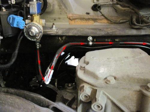
9 PAGE 8 076/ Water connections Cut original heater hose and connect the hoses with two connection pipes. Cut the original hose on the left side on the engine. Mount the 2 water couplings. Mount the hoses from the reducer to the water coupings. 8


10 PAGE 9 076/ Overpressure / MAP connection Drill a hole Ø5mm into the manifold and cut M6x1 thread into the hole for the MAP / overpressure coupling. Mount coupling with a locking compound. Connect hoses with Y-piece to reducer. Mount hose to MAP / overpressure coupling. Mount hose to reducer. 9


11 PAGE / Mounting the inlet manifold couplings Remove the inlet manifold. Drill 4 holes of 9 mm in the inlet manifold. Cut M10x1 thread in these holes. Place the VSI couplings with a lock compound in the inlet manifold. Watch out that the lock compound doesn t come inside the VSI couplings. Install hoses and place the inlet manifold back on the engine. Mount the VSI couplings to the inlet manifold. Mount the nylon hoses to the couplings. 10


12 PAGE / Mount the injection rail with the bracket. Mounting the VSI injector rail Mount bracket on original bolt from valve cover. Mount rail to bracket. Cut nylon hoses on right length and connect them to the rail with 6mm LPG hose. Beware of the order of the injectors. Cilinder 1 is located on the gear box side. 11

13 PAGE / Mounting the Prins filter unit Filter replacement must be recorded in the service book supplied Mount the filter with the supplied clamp & bolt to the injector rail bracket. LPG hoses Hose (Ø..mm) From component To component Hose length (cm) 16 Reducer Keihin filter unit Prins filter unit VSI injector rail 9 5 Reducer overpressure Y-piece 15 5 Reducer MAP connection Y-piece 10 5 Y-piece Inlet manifold coupling ( vacuum ) VSI injector 1 Nylon hose cyl VSI injector 2 Nylon hose cyl VSI injector 3 Nylon hose cyl VSI injector 4 Nylon hose cyl Nylon hoses through inlet couplings (cut on length later) 37,5 General info. Cut the LPG hoses on length. Cut the nylon hoses on length, make sure that the inlet of the nylon hose faces the injector outlet. Please observe that there is no damage or fouling to the hoses. 12


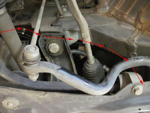
14 PAGE / Hose routing Connect 16mm LPG hose to reducer. Hose routing. Connect hose to filter. Connect 11mm hose from filter to injector rail. 13
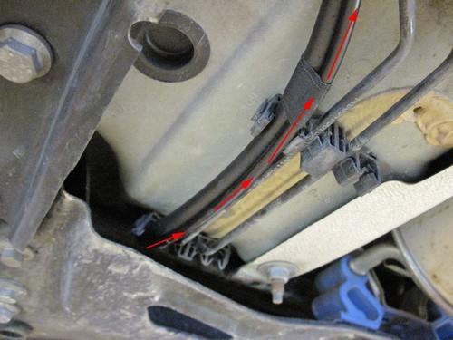
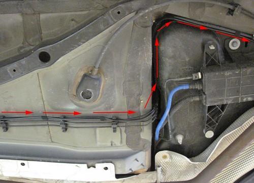
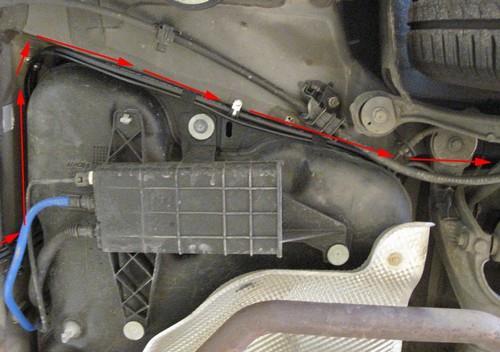
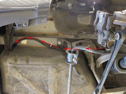
15 PAGE / Hose & wiring routing to tank 1 Mount fuel line connection. Hose & wiring routing. 14
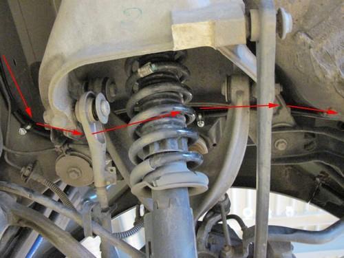
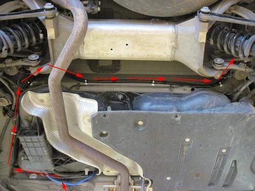
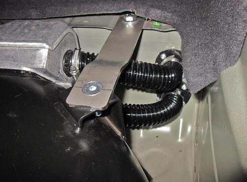
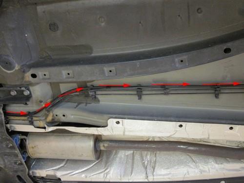
16 PAGE / Hose & wiring routing to tank 2 15


17 PAGE / Mounting the AFC Mount the plastic AFC clip to the reducer bracket with quick clips (3x). Mount the AFC to the plastic clip. Mounting the injection module / fuse holder Mount the injection module and the fuse holder to the bracket Mount the bracket to the original bolt in front of the battery. 16


18 PAGE / Mounting the fuel selection switch / CAN connection When mounting the switch, only push on its sides. Pushing the switch in the centre may result in damage to the switch. See general manual for programming the selection switch Drill hole 8,3mm and mount switch. EOBD connector. Wiring routing under bonnet. Wiring routing inside passenger room. 17


19 PAGE / Also see electrical connections. Petrol gauge reset module / Grommet Place reset module behind bonnet release. Ground under bonnet release. +15 and +30 on 16 pin grey connector on BCM underneath dashboard. Connection to fuel gauge in doorstep. Grommet for wire transit in left wheel arch. 18


20 PAGE / Electrical connections Driver room 51 CAN1 High 70 CAN1 Low Yellow Green Connect to EOBD diagnose connector Pin : 6 Pin : 14 3-pole micro connector 66 Ground fuel switch 3 +12V fuel switch 49 LIN fuel switch Brown-black Red-white Yellow Connect the 3-pole connector to the Prins fuel selection switch Ignition Red - grey Make a connection to ignition + / contact +. Do not place the fuse in the holder before having completed the installation of the LPG system. Wire colour : Green Wire location : BCM, grey 16p connector, pin 8 19
21 PAGE / Electrical connections Check and measure the wiring in case of changes in the cars wiring colours. Insulate not used wires. Wire number / code Wire colour Connection 32 Ground sense Brown 1 Ground battery Brown Connect to the ' ' of the battery; use a ring terminal or solder: Wire colour : Black Wire location : - (ground) battery 4 +12V Battery Red Do not place the fuse in the holder before having completed the installation of the LPG system. Wire colour : Red Wire location : + Battery G INJ OUT 1 White - yellow G + INJ 1 red G INJ OUT 2 Green - yellow Connector VSI-injector to cylinder G + INJ 2 red G INJ OUT 3 Pink - yellow Connector VSI-injector to cylinder G + INJ 3 red G INJ OUT 4 Blue - yellow Connector VSI-injector to cylinder G + INJ 4 red 22 LSS1 Purple Make a connection to the High Pressure Pump Actuator Wire colour : White Wire location : Petrol ECU, brown connector 53p, pin 45 Extend the LSS1 wire with an insulated / not used wire V Sensor 37 C ground 18 AD1 17 AD2 25 DAC1 Red blue (not used) Brown - black (not used) Blue - white Blue green Green - white Connector VSI-injector to cylinder 1. Gear box side!! For measuring the inlet manifold pressure (MAP). Wire colour : Yellow Wire location : Petrol ECU, brown 53p connector, pin 21 High pressure petrol sensor signal interruption. Sensor side. ECU side. Wire colour : Yellow Wire location : Petrol ECU, grey connector 32p, pin A3 63 Ground shift Blue orange Make a connection to boost pressure sensor. Wire colour : White Wire location : Petrol ECU, brown connector 53p, pin 13 8 RPM engine speed Purple - white For measuring the engine speed. Wire colour : Yellow Wire location : Petrol ECU, grey connector 32p, pin A2 38 AD7 10 DAC2 Blue light blue Green Boost sensor signal interruption. Sensor side. ECU side. Wire colour : Light blue Wire location : Petrol ECU, grey connector 32p, pin B4 20 AD3 Blue pink Make a connection to first lambda sonde. Wire colour : Yellow Wire location : Petrol ECU, brown connector 53p, pin Wake-up Grey red Make a connection +5V boost sensor. Wire colour : Blue Wire location : Petrol ECU, brown connector 53p, pin 38 Insulate not used wires 19 AD4 Blue Insulate 56 DI2 Yellow green Insulate Insulate additional not used wires 20
22 PAGE / Electrical connections Check and measure the wiring in case of changes in the cars wiring colours. For measuring the petrol injectors : Interrupt each petrol injector control wire (injector min) Each VSI wire has a petrol injector / cylinder number printed on the wire, connect this wire to the corresponding petrol injector / cylinder. Connect the bicoloured VSI measuring wire to the ecu side, ( wire code: ecu-lo ). Connect the corresponding full coloured VSI wire to the petrol injector side ( wire code: inj-lo ). See diagrams: Installation manual general part 1 / 2. Attention: Each bicoloured measuring wire corresponds to a specific LPG injector and petrol injector / cylinder number. Do not interchange the wires. Cylinder 1 is located at the gear box side!! Connect to 32p GREY connector on petrol ECU. VSI measure wire nr. : VSI wire inj / ecu 1 Petrol injector cyl. 1 VSI wire inj / ecu 2 Petrol injector cyl. 2 VSI wire inj / ecu 3 Petrol injector cyl. 3 VSI wire inj / ecu 4 Petrol injector cyl. 4 Module wire pos. H1 ECU HIGH A ( cil. 1-4 ) Module wire pos. H2 ECU HIGH B ( cil. 2-3 ) Full coloured / Bicoloured Module position white / white-yellow B2 / A2 green / green-yellow A1 / C2 pink / pink-yellow E1 / F2 blue / blue-yellow D1 / D2 red-yellow H1 red-green H2 Interrupt petrol injector wire Colour : White Location : E4 Colour : White Location : C4 Colour : White Location : F4 Colour : White Location : D4 Colour : Orange Location : F1 Colour : Orange Location : C1 21

23 PAGE / Electrical connections Connectors in wiring loom 2-pole blue connector 15 T-ECT 34 Ground T-ECT 4-pole connector 35 Ground Psys 14 T-Gas 9 +5 Volt sensor 16 Psys 2-pole connector V reducer lock-off 31 C Ground 4-pole connector 46 Service TxD 65 Service RxD 68 Ground PDT Grey Brown - black Brown - black Grey Red - blue green Yellow - green Brown - black Grey Grey Brown - black For measuring the engine coolant temperature ( Tect ). Connect the connector to the reducer temperature sensor. For measuring gas pressure and gas temperature. Connect the connector to the filter unit sensor. Connect the connector to the reducer lock-off valve. Diagnose connector. Tank wiring loom 2 +12V Tank relay 12 Tank level IN 26 Ground tank relay Wiring loom link 45 C ground V switched 64 AD5 red blue black Brown black Red white Blue - grey Connect to the tank lock-off. Connect the tank level gauge. Connect to the tank lock-off. Connection from AFC connector A to connector B Optional: 3-pole connector 11 + manometer 12 tank level in 33 ground manometer red blue brown Cut off connector and insulate wires 22
24 PAGE / Electrical connections petrol gauge reset module (2 options) 23
25 PAGE / Checklist after installation 1. Connect the serial interface wire and run the VSI diagnosis program. Install the VSI fuse, and program the switch. Turn the ignition key in the accessory position. When working on the car, beware of moving and rotating parts in the engine compartment. 2. When commissioning the LPG system, you must activate the VSI computer with the diagnosis software. When the VSI computer has not been activated, it will keep generating error code 160. To activate the VSI computer, select function F11 (activate ECM). 3. Check whether the program in the VSI computer matches with the car ( dedicated engine set ): Refer with F2 to the box number and car description in the diagnosis software and compare these with the set number. 4. The system will switch over to LPG as soon as the temperature of the coolant (T-ect) becomes higher than the parameter T-min set and when the TSO-cold time is expired. 5. Check all components and connections for any gas leakage ( use a LPG leak detector device or a fluid detection like soap. Caution for moving and rotating parts in the engine compartment! 6. Let the engine run warm on petrol >80 C. Check if the evaporator heats up. Check the engine signals, petrol injection time, RPM, ECT, lambda, MAP signal, petrol pressure signal. Let the engine run idle on LPG. Adjust the evaporator pressure. Refer to the parameter list ( or F2 : ID box) for the idle level value set. Adjust the evaporator pressure in such a way that the pressure measured ( P-sys ) equals the idle level value. Turn the socket-head screw at the front of the evaporator to adjust the pressure. An error code will be generated whenever the pressure variation is to high. Seal the evaporator with the sticker included in the delivery after having adjusted the pressure. 7. Use the diagnosis software to check again all input and output signals. 8. Check the system for error codes and solve these, if required. Check the petrol MMS for EOBD error codes. Place the protection connector on the VSI communication connector. 9. Make a test drive and check the drivability on LPG and petrol. 24
MANUFACTURER Explorer Sport ENGINE DISPLACEMENT NUMBER OF VALVES FIRING ORDER VEHICLE CATEGORIES TRANSMISSION
 MANUFACTURER Ford TYPE Explorer Sport ENGINE DISPLACEMENT 3500cc NUMBER OF VALVES 24v ENGINE CODE / NUMBER 3.5L GTDi Ecoboost FIRING ORDER 1 4 2 5-3 - 6 VEHICLE CATEGORIES M TRANSMISSION AT VERSION AFC-2.1
MANUFACTURER TYPE F-150 ENGINE DISPLACEMENT NUMBER OF VALVES FIRING ORDER VEHICLE CATEGORIES TRANSMISSION
 MANUFACTURER Ford TYPE F-150 ENGINE DISPLACEMENT 3500cc NUMBER OF VALVES 24v ENGINE CODE / NUMBER - OUTPUT 3.5L EcoBoost 2015 365hp FIRING ORDER 1-4-2-5-3-6 VEHICLE CATEGORIES M TRANSMISSION AT VERSION
MODEL YEAR: 2010 SYSTEM APPROVAL NUMBER ( R115 ) R ENGINE SET NUMBER 349/ (.06 /.07 )
 R ENGINE SET NUMBER 349/ (.06 /.07 )") MAKE OF AUTOMOBILE: TYPE: IX35 PISTON DISPLACEMENT: 2000 NUMBER OF VALVES: 16 ENGINE NUMBER: G4KD TRANSMISSION TYPE ( MT / AT ) MT VEHICLE CATEGORIES M or N M TYPE VSI INJECTOR ( COLOUR ) Orange VERSION
MAKE OF AUTOMOBILE: TYPE: IX35 PISTON DISPLACEMENT: 2000 NUMBER OF VALVES: 16 ENGINE NUMBER: G4KD TRANSMISSION TYPE ( MT / AT ) MT VEHICLE CATEGORIES M or N M TYPE VSI INJECTOR ( COLOUR ) Orange VERSION
ENGINE DISPLACEMENT 2000 NUMBER OF VALVES 16 ENGINE SET NUMBER
 MANUFACTURER Subaru TYPE Forester ENGINE DISPLACEMENT 2000 NUMBER OF VALVES 16 ENGINE CODE / NUMBER FA20 DIT VEHICLE CATEGORIES M TRANSMISSION AT VERSION Direct LiquiMax-2.1 PETROL ECU MANUFACTURER / CODE
MAKE OF AUTOMOBILE: MODEL YEAR: 2004 SYSTEM APPROVAL NUMBER ( R115 ) ENGINE SET NUMBER 336/
 ENGINE SET NUMBER 336/") MAKE OF AUTOMOBILE: TYPE: A4 PISTON DISPLACEMENT: 1800 NUMBER OF VALVES: 20V ENGINE NUMBER: BFB TRANSMISSION TYPE ( MT / AT ) AT VEHICLE CATEGORIES M or N M TYPE VSI INJECTOR ( NUMBER + COLOR ) YELLOW
MAKE OF AUTOMOBILE: TYPE: A4 PISTON DISPLACEMENT: 1800 NUMBER OF VALVES: 20V ENGINE NUMBER: BFB TRANSMISSION TYPE ( MT / AT ) AT VEHICLE CATEGORIES M or N M TYPE VSI INJECTOR ( NUMBER + COLOR ) YELLOW
MAKE OF AUTOMOBILE: MODEL YEAR: 2007 SYSTEM APPROVAL NUMBER ( R115 ) R ENGINE SET NUMBER 349/
 R ENGINE SET NUMBER 349/") MAKE OF AUTOMOBILE: KIA TYPE: CARENS PISTON DISPLACEMENT: 2000 NUMBER OF VALVES: 16 ENGINE NUMBER: G4KA TRANSMISSION TYPE ( MT / AT ) MT VEHICLE CATEGORIES M or N M TYPE VSI INJECTOR ( COLOUR ) ORANGE
MAKE OF AUTOMOBILE: KIA TYPE: CARENS PISTON DISPLACEMENT: 2000 NUMBER OF VALVES: 16 ENGINE NUMBER: G4KA TRANSMISSION TYPE ( MT / AT ) MT VEHICLE CATEGORIES M or N M TYPE VSI INJECTOR ( COLOUR ) ORANGE
MAKE OF AUTOMOBILE: ENGINE SET NUMBER 348/
 MAKE OF AUTOMOBILE: TYPE: CIVIC PISTON DISPLACEMENT: 1800 NUMBER OF VALVES: 16 ENGINE NUMBER: R18A TRANSMISSION TYPE ( MT / AT ) MT VEHICLE CATEGORIES M or N M TYPE VSI INJECTOR ( COLOR ) ORANGE VERSION
PISTON DISPLACEMENT: NUMBER OF VALVES: 16. TRANSMISSION TYPE ( MT / AT ) VEHICLE CATEGORIES M or N TYPE VSI INJECTOR ( COLOUR ) VERSION ( LPG / CNG )
 VEHICLE CATEGORIES M or N TYPE VSI INJECTOR ( COLOUR ) VERSION ( LPG / CNG )") MAKE OF AUTOMOBILE: TYPE: Ram PISTON DISPLACEMENT: 5700cc NUMBER OF VALVES: 16 ENGINE NUMBER: 5.7V8 Hemi 290kW TRANSMISSION TYPE ( MT / AT ) AT VEHICLE CATEGORIES M or N M TYPE VSI INJECTOR ( COLOUR )
MAKE OF AUTOMOBILE: TYPE: Ram PISTON DISPLACEMENT: 5700cc NUMBER OF VALVES: 16 ENGINE NUMBER: 5.7V8 Hemi 290kW TRANSMISSION TYPE ( MT / AT ) AT VEHICLE CATEGORIES M or N M TYPE VSI INJECTOR ( COLOUR )
ENGINE DISPLACEMENT NUMBER OF VALVES 16 VEHICLE CATEGORIES
 MANUFACTURER Dacia TYPE Duster ENGINE DISPLACEMENT 1200cc NUMBER OF VALVES 16 ENGINE CODE / NUMBER H5F (TCe125) VEHICLE CATEGORIES M TRANSMISSION MT (6-speed) VERSION AFC-2.1 PETROL ECU MANUFACTURER /
MAKE OF AUTOMOBILE: 316 / 318i E46 NUMBER OF VALVES:
 MAKE OF AUTOMOBILE: TYPE: 316 / 318i E46 PISTON DISPLACEMENT: 1800 2000 cc NUMBER OF VALVES: 16V ENGINE NUMBER: N42B18A / N42B20A TRANSMISSION TYPE ( MT / AT ) MT VEHICLE CATEGORIES M or N M TYPE VSI INJECTOR
MODEL YEAR: 2009 SYSTEM APPROVAL NUMBER ( R115 ) R ENGINE SET NUMBER 350/
 R ENGINE SET NUMBER 350/") MAKE OF AUTOMOBILE: TYPE: PRIORA 2170 / 2172 PISTON DISPLACEMENT: 1600 NUMBER OF VALVES: 16 ENGINE NUMBER: 21126 TRANSMISSION TYPE ( MT / AT ) MT VEHICLE CATEGORIES M or N M TYPE VSI INJECTOR (COLOR )
MAKE OF AUTOMOBILE: TYPE: PRIORA 2170 / 2172 PISTON DISPLACEMENT: 1600 NUMBER OF VALVES: 16 ENGINE NUMBER: 21126 TRANSMISSION TYPE ( MT / AT ) MT VEHICLE CATEGORIES M or N M TYPE VSI INJECTOR (COLOR )
MAKE OF AUTOMOBILE: PISTON DISPLACEMENT: 1300
 MAKE OF AUTOMOBILE: TYPE: YARIS PISTON DISPLACEMENT: 1300 NUMBER OF VALVES: 16 VVT-I ENGINE NUMBER: 2SZ-FE TRANSMISSION TYPE ( MT / AT ) AT VEHICLE CATEGORIES M or N M TYPE VSI INJECTOR ( NUMBER + COLOR
MAKE OF AUTOMOBILE: ENGINE SET NUMBER 366/
 MAKE OF AUTOMOBILE: TYPE: SORENTO PISTON DISPLACEMENT: 3300 NUMBER OF VALVES: 24 ENGINE NUMBER: G6DB TRANSMISSION TYPE ( MT / AT ) MT VEHICLE CATEGORIES M or N M TYPE VSI INJECTOR ( NUMBER + COLOR ) 180/30340
MODEL YEAR: SYSTEM APPROVAL NUMBER ( R115 ) R ENGINE SET NUMBER 354/
 R ENGINE SET NUMBER 354/") MAKE OF AUTOMOBILE: MERECEDES TYPE: E200 W211 PISTON DISPLACEMENT: 1796 NUMBER OF VALVES: 16 ENGINE NUMBER: M271 TRANSMISSION TYPE ( MT / AT ) AT VEHICLE CATEGORIES M or N M TYPE VSI INJECTOR ( NUMBER
MAKE OF AUTOMOBILE: MERECEDES TYPE: E200 W211 PISTON DISPLACEMENT: 1796 NUMBER OF VALVES: 16 ENGINE NUMBER: M271 TRANSMISSION TYPE ( MT / AT ) AT VEHICLE CATEGORIES M or N M TYPE VSI INJECTOR ( NUMBER
MAKE OF AUTOMOBILE: MODEL YEAR: 2007 SYSTEM APPROVAL NUMBER ( R115 ) VSI-LPG 10 ENGINE SET NUMBER 364/
 VSI-LPG 10 ENGINE SET NUMBER 364/") MAKE OF AUTOMOBILE: TYPE: FABIA PISTON DISPLACEMENT: 1400 NUMBER OF VALVES: 16 ENGINE NUMBER: BUD TRANSMISSION TYPE ( MT / AT ) MT VEHICLE CATEGORIES M or N M TYPE VSI INJECTOR ( NUMBER + COLOR ) 180/30410
MAKE OF AUTOMOBILE: TYPE: FABIA PISTON DISPLACEMENT: 1400 NUMBER OF VALVES: 16 ENGINE NUMBER: BUD TRANSMISSION TYPE ( MT / AT ) MT VEHICLE CATEGORIES M or N M TYPE VSI INJECTOR ( NUMBER + COLOR ) 180/30410
PISTON DISPLACEMENT: 1200 NUMBER OF VALVES: ENGINE NUMBER: TRANSMISSION TYPE ( MT / AT ) VEHICLE CATEGORIES M or N TYPE VSI INJECTOR (COLOUR )
 VEHICLE CATEGORIES M or N TYPE VSI INJECTOR (COLOUR )") MAKE OF AUTOMOBILE: VOLKSWAGEN TYPE: POLO PISTON DISPLACEMENT: 1200 NUMBER OF VALVES: 8V ENGINE NUMBER: BZG TRANSMISSION TYPE ( MT / AT ) MT VEHICLE CATEGORIES M or N M TYPE VSI INJECTOR (COLOUR ) BLUE
MAKE OF AUTOMOBILE: VOLKSWAGEN TYPE: POLO PISTON DISPLACEMENT: 1200 NUMBER OF VALVES: 8V ENGINE NUMBER: BZG TRANSMISSION TYPE ( MT / AT ) MT VEHICLE CATEGORIES M or N M TYPE VSI INJECTOR (COLOUR ) BLUE
MAKE OF AUTOMOBILE: TYPE: V 70 PISTON DISPLACEMENT: 2521 NUMBER OF VALVES:
 MAKE OF AUTOMOBILE: TYPE: V 70 PISTON DISPLACEMENT: 2521 NUMBER OF VALVES: 20V ENGINE NUMBER: B5254T TRANSMISSION TYPE ( MT / AT ) AT VEHICLE CATEGORIES M or N PASSENGER CAR ( M ) TYPE VSI INJECTOR (COLOUR
MODEL YEAR: 2007 SYSTEM APPROVAL NUMBER ( R115 ) R ENGINE SET NUMBER 350/
 R ENGINE SET NUMBER 350/") MAKE OF AUTOMOBILE: TYPE: KALINA 1117/ 1118 / 1119 PISTON DISPLACEMENT: 1600 NUMBER OF VALVES: 8 ENGINE NUMBER: 21114 TRANSMISSION TYPE ( MT / AT ) MT VEHICLE CATEGORIES M or N M TYPE VSI INJECTOR ( NUMBER
MAKE OF AUTOMOBILE: TYPE: KALINA 1117/ 1118 / 1119 PISTON DISPLACEMENT: 1600 NUMBER OF VALVES: 8 ENGINE NUMBER: 21114 TRANSMISSION TYPE ( MT / AT ) MT VEHICLE CATEGORIES M or N M TYPE VSI INJECTOR ( NUMBER
MAKE OF AUTOMOBILE: PISTON DISPLACEMENT: 2700 NUMBER OF VALVES:
 MAKE OF AUTOMOBILE: DODGE TYPE: JOURNEY PISTON DISPLACEMENT: 2700 NUMBER OF VALVES: 24V ENGINE NUMBER: 2.7V6 EER TRANSMISSION TYPE ( MT / AT ) AT VEHICLE CATEGORIES M or N M TYPE VSI INJECTOR ( COLOR )
ENGINE DISPLACEMENT NUMBER OF VALVES ENGINE SET NUMBER VEHICLE CATEGORIES. Direct LiquiMax-2.0 PETROL ECU MANUFACTURER / CODE Bosch MED 17.
 MANUFACTURER VOLVO TYPE V60 / V70 T4F ENGINE DISPLACEMENT 1600cc NUMBER OF VALVES 16v ENGINE CODE / NUMBER B4164T2 VEHICLE CATEGORIES M TRANSMISSION MT/AT VERSION Direct LiquiMax-2.0 PETROL ECU MANUFACTURER
MAKE OF AUTOMOBILE: PISTON DISPLACEMENT: 8300 NUMBER OF VALVES: 20 TRANSMISSION TYPE ( MT / AT ) TYPE VSI INJECTOR (COLOR ) VERSION ( LPG / CNG )
 TYPE VSI INJECTOR (COLOR ) VERSION ( LPG / CNG )") MAKE OF AUTOMOBILE: TYPE: PISTON DISPLACEMENT: 8300 NUMBER OF VALVES: 20 ENGINE NUMBER: SRT V10 Viper TRANSMISSION TYPE ( MT / AT ) AT TYPE VSI INJECTOR (COLOR ) YELLOW VERSION ( LPG / CNG ) LPG INJECTION
MAKE OF AUTOMOBILE: TYPE: PISTON DISPLACEMENT: 8300 NUMBER OF VALVES: 20 ENGINE NUMBER: SRT V10 Viper TRANSMISSION TYPE ( MT / AT ) AT TYPE VSI INJECTOR (COLOR ) YELLOW VERSION ( LPG / CNG ) LPG INJECTION
MAKE OF AUTOMOBILE: ENGINE SET NUMBER 337/
 MAKE OF AUTOMOBILE: TYPE: NITRO PISTON DISPLACEMENT: 3700 NUMBER OF VALVES: 12V ENGINE NUMBER: V6 TRANSMISSION TYPE ( MT / AT ) AT VEHICLE CATEGORIES M or N M TYPE VSI INJECTOR ( NUMBER + COLOR ) 180/30330
MAKE OF AUTOMOBILE: GRAND CHEROKEE PISTON DISPLACEMENT: 5700 NUMBER OF VALVES: 16
 MAKE OF AUTOMOBILE: TYPE: GRAND CHEROKEE PISTON DISPLACEMENT: 5700 NUMBER OF VALVES: 16 ENGINE NUMBER: 5.7V8 HEMI TRANSMISSION TYPE ( MT / AT ) AT VEHICLE CATEGORIES M or N M TYPE VSI INJECTOR ( NUMBER
Megane Estate ENGINE DISPLACEMENT NUMBER OF VALVES VEHICLE CATEGORIES
 MANUFACTURER Renault TYPE Megane Estate ENGINE DISPLACEMENT 1200cc NUMBER OF VALVES 16v ENGINE CODE / NUMBER H5F (TCe115) VEHICLE CATEGORIES M TRANSMISSION MT(6) VERSION AFC-2.1 PETROL ECU MANUFACTURER
Prins autogassystemen b.v. Veldhoven
 Prins autogassystemen b.v. Veldhoven MOUNTING INSTRUCTION ENGINE CONVERSION SET MAKE OF AUTOMOBILE: TYPE: ASTRA PISTON DISPLACEMENT: 2000 cc MT NUMBER OF VALVES: 16V ENGINE NUMBER: X20XEV INJECTION SYSTEM:
MAKE OF AUTOMOBILE: ENGINE SET NUMBER 345/ NUMBER : 076/ DATE : VERSION NR : B
 MAKE OF AUTOMOBILE: TYPE: LOGAN PISTON DISPLACEMENT: 1600 NUMBER OF VALVES: 8 ENGINE NUMBER: K7M 710 TRANSMISSION TYPE ( MT / AT ) MT VEHICLE CATEGORIES M or N ( M ) TYPE VSI INJECTOR ( NUMBER + COLOR
MAKE OF AUTOMOBILE: NUMBER : 076/ DATE : Copyright Prins Autogassystemen B.V VERSION NR : B
 MAKE OF AUTOMOBILE: Ford TYPE: Mondeo PISTON DISPLACEMENT: 2000 NUMBER OF VALVES: 16 ENGINE NUMBER: AOBA TYPE VSI INJECTOR ( COLOR ) Yellow MODEL YEAR: 2010 ENGINE SET NUMBER 347/1810500.07 NUMBER : 076/0703201
MAKE OF AUTOMOBILE: PISTON DISPLACEMENT: 1600 NUMBER OF VALVES: 16
 MAKE OF AUTOMOBILE: TYPE: MERIVA PISTON DISPLACEMENT: 1600 NUMBER OF VALVES: 16 ENGINE NUMBER: Z16XEP TRANSMISSION TYPE ( MT / AT ) MT VEHICLE TYPE M TYPE VSI INJECTOR ( NUMBER + COLOR ) 180/30430 ORANGE
MAKE OF AUTOMOBILE: PISTON DISPLACEMENT: NUMBER OF VALVES: ENGINE NUMBER: TRANSMISSION TYPE ( MT / AT ) VEHICLE CATEGORIES M or N PERSONEN AUTO ( M )
 VEHICLE CATEGORIES M or N PERSONEN AUTO ( M )") MAKE OF AUTOMOBILE: TYPE: WRANGLER PISTON DISPLACEMENT: 4000 cc NUMBER OF VALVES: 12 v ENGINE NUMBER: M3 TJ TRANSMISSION TYPE ( MT / AT ) MT VEHICLE CATEGORIES M or N PERSONEN AUTO ( M ) TYPE VSI INJECTOR
MAKE OF AUTOMOBILE: TYPE: WRANGLER PISTON DISPLACEMENT: 4000 cc NUMBER OF VALVES: 12 v ENGINE NUMBER: M3 TJ TRANSMISSION TYPE ( MT / AT ) MT VEHICLE CATEGORIES M or N PERSONEN AUTO ( M ) TYPE VSI INJECTOR
Universal instructions CNG Tank-sets. MODEL year 2011 SET Number. NUMMER : DATE : Copyright Prins Autogassystemen B.V VERSIE NR : DB
 Universal instructions CNG Tank-sets Make universal MODEL year 2011 SET Number all NUMMER : DATE : 2011-09-12 TABLE OF CONTENTS... 1 Required equipment / tools / materials for installing a complete system...
Required equipment / tools / materials for installing a complete system. Vehicle check
 2-2017 Table of contents Required equipment / tools / materials for installing a complete system 3 Vehicle check 3 General instructions 4 Tightening moments 5 Direct LiquiMax Gen1 & Gen2 components 6 Approval
MAKE OF AUTOMOBILE: MODEL YEAR: 2013 SYSTEM APPROVAL NUMBER ( R115 ) R MANUAL NUMBER: 076/ DATE
 R MANUAL NUMBER: 076/ DATE") MAKE OF AUTOMOBILE: Dacia TYPE: Lodgy TANK CAPACITY: 59 Liter Stako toroidal TANK LOCATION Spare Wheel Room / Underneath MODEL YEAR: 2013 SYSTEM APPROVAL NUMBER ( R115 ) R115-000013 BOOT SET NUMBER 345/070002/A
MAKE OF AUTOMOBILE: Dacia TYPE: Lodgy TANK CAPACITY: 59 Liter Stako toroidal TANK LOCATION Spare Wheel Room / Underneath MODEL YEAR: 2013 SYSTEM APPROVAL NUMBER ( R115 ) R115-000013 BOOT SET NUMBER 345/070002/A
MAKE OF AUTOMOBILE: MODEL YEAR: SYSTEM APPROVAL NUMBER ( R115 ) E4-115R /-17 / DLM-LPG 01/10 MANUAL NUMBER: 076/ DATE
 E4-115R /-17 / DLM-LPG 01/10 MANUAL NUMBER: 076/ DATE") MAKE OF AUTOMOBILE: HYUNDAI TYPE: ix35 TANK CAPACITY: 74 Liter Fuel Module Stako toroidal TANK LOCATION SPARE WHEEL ROOM MODEL YEAR: 2010 SYSTEM APPROVAL NUMBER ( R115 ) E4-115R-0000-04/-17 / DLM-LPG 01/10
MAKE OF AUTOMOBILE: HYUNDAI TYPE: ix35 TANK CAPACITY: 74 Liter Fuel Module Stako toroidal TANK LOCATION SPARE WHEEL ROOM MODEL YEAR: 2010 SYSTEM APPROVAL NUMBER ( R115 ) E4-115R-0000-04/-17 / DLM-LPG 01/10
MAKE OF AUTOMOBILE: MODEL YEAR: 2010 SYSTEM APPROVAL NUMBER ( R115 ) BOOT SET NUMBER 947/
 BOOT SET NUMBER 947/") MAKE OF AUTOMOBILE: FORD TYPE: MONDEO TANK CAPACITY: 61 Liter WvM toroidal TANK LOCATION SPARE WHEEL ROOM MODEL YEAR: 2010 SYSTEM APPROVAL NUMBER ( R115 ) R115-0000** BOOT SET NUMBER 947/1810501 NUMBER:
MAKE OF AUTOMOBILE: FORD TYPE: MONDEO TANK CAPACITY: 61 Liter WvM toroidal TANK LOCATION SPARE WHEEL ROOM MODEL YEAR: 2010 SYSTEM APPROVAL NUMBER ( R115 ) R115-0000** BOOT SET NUMBER 947/1810501 NUMBER:
DATE : VERSION NR :
 DATE : 07032006 VERSION NR : B Table of contents General instructions 2 Introduction 3 Overview VSI system 4 Approval numbers VSI components 4 The ucer 5 The injector rail 6 The filter unit 7 The VSI computer
MAKE OF AUTOMOBILE: GRAND VOYAGER STOW`N GO MODEL YEAR: NUMBER: 076/ Copyright Prins Autogassystemen B.V DATE:
 MAKE OF AUTOMOBILE: CHRYSLER TYPE: GRAND VOYAGER STOW`N GO TANK CAPACITY: 2X 36Liter Stako toroidal TANK LOCATION FRONT SEAT ROOM MODEL YEAR: NUMBER: 076/3211036 Copyright Prins Autogassystemen B.V. 2008
WORLD LEADER IN ALTERNATIVE FUEL SYSTEMS CALIBRATION PARAMETERS
 WORLD LEADER IN ALTERNATIVE FUEL SYSTEMS CALIBRATION PARAMETERS VSI-2.0 LPG UNIVERSAL KIT Version: Back V2.4 to Parameter 03-2018 Overview Page 1 of 53 Copyright Prins Autogassystemen B.V. 2018 Back to
Fuel injection system, servicing
 24-1 Fuel injection system, servicing Component locations overview 1 - Oxygen sensor 1 before Three Way Catalyst G39 2 - Oxygen sensor 2 after Three Way Catalyst G130 3 - Engine Coolant Temperature sensor
Installation Instructions General Motors 8.1 Sequential Vapor Injection (S.V.I.) System 7500/6500 Series Trucks model year.
 System 7500/6500 Series Trucks model year.") Installation Instructions General Motors 8.1 Sequential Vapor Injection (S.V.I.) System 7500/6500 Series Trucks 2003-2005 model year. Technocarb Equipment (2004) Ltd. 4-30435 Progressive Way Abbotsford,
Installation Instructions General Motors 8.1 Sequential Vapor Injection (S.V.I.) System 7500/6500 Series Trucks 2003-2005 model year. Technocarb Equipment (2004) Ltd. 4-30435 Progressive Way Abbotsford,
Nero 6600H/6601H. Installation Guide. Commercial Vehicle Productivity and Security. Antenna Configuration
 Commercial Vehicle Productivity and Security The 6600H/6601H is a versatile and economical GPS tracking beacon designed for fleet management needs in all commercial vehicles. The H designation in the model
Installation And Programming Manual of OPTIMA Eco Tec and OPTIMA Pro Tec OBD/CAN
 v1.03 [EN] Installation And Programming Manual of OPTIMA Eco Tec and OPTIMA Pro Tec OBD/CAN ALEX Zambrowska 4A, 16-001 Kleosin Poland tel./fax: +48 85 664 84 40 www.optimagas.pl e-mail: service@optimagas.pl
1998 ENGINE PERFORMANCE. General Motors Corp. - Basic Diagnostic Procedures - 5.7L
 INTRODUCTION 1998 ENGINE PERFORMANCE General Motors Corp. - Basic Diagnostic Procedures - 5.7L The following diagnostic steps will help prevent overlooking a simple problem. This is also where to begin
Installation instructions
 Service Installation instructions Audi A4/A5 (B8 series) 2008 Engine sound system For scope of delivery 8T0.071.901* Audi Genuine Accessories Service Department. Technical Information Service Contents
PowerJet Sequential Injection INDEX. 1 Introduction 1.1 Features of the Software. 2- Software installation
 INDEX 1 Introduction 1.1 Features of the Software 2- Software installation 3 Open the program 3.1 Language 3.2 Connection 4 Folder General - F2. 4.1 The sub-folder Error visualization 5 Folder Configuration
LAMBDA SENSOR CONTROLLER
 LAMBDA SENSOR CONTROLLER INSTALLATION & PROGRAMMING MANUAL version : V1.77 -V1.79 Manufacturer: AC Spółka Akcyjna. 15-182 Białystok, ul. 27 Lipca 64, Poland tel. +48 85 7438148, fax +48 85 653 8649 www.ac.com.pl,
TELORVEK EFI 5.0 Coyote Sequential Fuel Injection System Part # CY-11
 Page #1 TELORVEK EFI 5.0 Coyote Sequential Fuel Injection System Part # CY-11 WIRING INSTRUCTIONS Thank you for purchasing the absolute finest of wiring kits for the Ford Motor Co. Coyote modular engine.
INDEX 1 Introduction 2- Software installation 3 Open the program 4 General - F2 5 Configuration - F3 6 - Calibration - F5 7 Model - F6 8 - Map - F7
 SET UP MANUAL INDEX 1 Introduction 1.1 Features of the Software 2- Software installation 3 Open the program 3.1 Language 3.2 Connection 4 General - F2 4.1 The sub-folder Error visualization 5 Configuration
Alternative Fuel Engine Control Unit
 1999 Chevrolet/Geo Cavalier (CNG) Alternative Fuel Engine Control Unit Table 1: AF ECU Function Parameters The (AF ECU) controls alternative fuel engine operation. The control unit monitors various engine
Using the Gratec Gasoline software
 Using the Gratec Gasoline software The Gratec Software is a sophisticated yet user friendly program in which configures the Gratec CNG or LPG system to perform with your vehicle. Software version 2.002
3.4L V6 SUPERCHARGER 7 TH INJECTOR KIT
 Part Number: 00602-17620-260 00602-17620-261 00602-17620-263 00602-17620-264 00602-17620-274 00602-17620-275 00602-17620-276 Section I Installation Preparation Kit Contents Item # Quantity Reqd. Description
VT Commodore LPG installation utilising an LPG Memcal and Apexus Quick-kit.
 VT Commodore LPG installation utilising an LPG Memcal and Apexus Quick-kit. Description of components and operation LPG/Petrol Changeover switch The LPG change-over switch is mounted in the instrument
DieselBlend LPG. a Westport Fuel Systems company
 a Westport Fuel Systems company DieselBlend LPG Prins Autogassystemen B.V., specialized in alternative fuel systems, developed a new dual-fuel system for heavy-duty applications: Prins Dieselblend LPG
Preparing and programming of ESGI 2 LPG supply system manual
 Preparing and programming of ESGI 2 LPG supply system manual Part II Instruction of preparing and programming the ESGI system 1 Technical data of the central unit Vs Power supply voltage 0...16V V i_an
16A. STARTING - CHARGING Starter: Removal - Refitting REFITTING 16A-11 K4M II - REMOVAL OPERATION III - FINAL OPERATION
 STARTING - CHARGING Starter: Removal - Refitting 16A K4M II - REMOVAL OPERATION III - FINAL OPERATION JR5 a Clip: -the gearbox control cable sleeve stops on the gearbox, - the control cables onto the gearbox.
MegaSquirt III for Gen 3 HEMI. Hardware Install THE FOLLOWING SENSOR PART NUMBERS APPLY TO ALL HARNESSES FOR ENGINES 2004 TO CURRENT:
 MegaSquirt III for Gen 3 HEMI MegaSquirt controllers are experimental devices intended for educational purposes. MegaSquirt controllers are not for sale or use on pollution controlled vehicles. Check the
G - TESTS W/CODES - 2.2L
 G - TESTS W/CODES - 2.2L 1994 Toyota Celica 1994 ENGINE PERFORMANCE Toyota 2.2L Self-Diagnostics Celica INTRODUCTION If no faults were found while performing F - BASIC TESTING, proceed with self-diagnostics.
Malfunction Criteria and Threshold Value Adaptive value. Secondary Parameters with Enable Conditions. >50.8 S Engine load 9-45% Delta fuel adaptation
 DTC Error Message P0171 System Too Lean (Bank 1) Diagnostic Procedure Check fuel pump delivery and quantity. Refer to page 126. Check Fuel pressure regulator and residual pressure. Refer to Fuel Injection
Wiring for OMS/Mid-engine layout
 Wiring for OMS/Mid-engine layout Coil connectors Crank sensor Coolant temperature sensor Cam sensor Connector for fuel pump Connector for joining new wiring harness to existing Suzuki wiring will need
EVAP system, servicing
 Page 1 of 65 20-130 EVAP system, servicing EVAP system components 1 - Cap nut 10 Nm 2 - Cover 3 - Stud For EVAP canister 15 Nm 4 - Sealing piece 5 - Bleed line To EVAP canister purge regulator valve -
NATEF ENGINE PERFORMANCE CHECKLIST Name Date Period
 NATEF ENGINE PERFORMANCE CHECKLIST Name Period For every task in Engine Performance the following safety requirement must be strictly enforced: Comply with personal and environmental safety practices associated
C FORD F250 / F L POWERSTROKE DIESEL WITH AUTOMATIC TRANSMISSIONS ONLY
 EXHAUST BRAKES C40019 1999-2003 FORD F250 / F350 7.3L POWERSTROKE DIESEL WITH AUTOMATIC TRANSMISSIONS ONLY Getting Started Thank you and congratulations on your purchase of a Pacbrake exhaust retarder.
Technical Installation Guide
 Technical Installation Guide ID Technical Document: DT_IS_GAI-005 Rev. Date Review n. Issued by Reviewed/ Approved 0 13/04/2007 First Issue Technical office ROS 1 19/02/2009 Second Issue Technical office
HOWELL INSTALLATION MANUAL. Throttle Body Fuel Injection Harness
 HOWELL ENGINE DEVELOPMENTS, INC. FUEL INJECTION APPLICATIONS INSTALLATION MANUAL Throttle Body Fuel Injection Harness Howell Engine Developments, Inc. 6201 Industrial Way Marine City, MI 48039 Phone: 810-765-5100
Audi A4 Current Flow Diagram No. 44 / 1 Edition
 Page 1 of 16 Audi A4 Current Flow Diagram No. 44 / 1 Edition 05.2003 1.8 l - Fuel injection engine (110 kw - Motronic - 4 cylinder), engine code AVJ from model year 2002 1.8 l - Fuel injection engine (120
VERSUS Installation manual Contents:
 VERSUS Installation manual Contents: 1. INTRODUCTION - SGI ECU VERSUS... 2 1.1. Initial recommendations... 2 1.2. Scheme no 1: General scheme of VERSUS system installation (4 cyl. engine sample)... 3 2.
Fitting Instructions: Street Triple from VIN and Street Triple R from VIN A
 English Fitting Instructions: Street Triple from VIN 560477 and Street Triple R from VIN 560477 A9808113 Thank you for choosing this Triumph genuine accessory kit. This accessory kit is the product of
Idle Timer Controller - ITC Freightliner MT45 Contact InterMotive for additional vehicle applications
 An ISO 9001:2008 Registered Company System Operation Idle Timer Controller - ITC805 2013-2018 Freightliner MT45 Contact InterMotive for additional vehicle applications The ITC805 system shuts down idling
2002 ENGINE PERFORMANCE. Self-Diagnostics - RAV4. Before performing testing procedures, check for any related Technical Service Bulletins (TSBs).
.") 2002 ENGINE PERFORMANCE Self-Diagnostics - RAV4 INTRODUCTION NOTE: Before performing testing procedures, check for any related Technical Service Bulletins (TSBs). To properly diagnosis and repair this
2002 ENGINE PERFORMANCE Self-Diagnostics - RAV4 INTRODUCTION NOTE: Before performing testing procedures, check for any related Technical Service Bulletins (TSBs). To properly diagnosis and repair this
Chapter 4 Part D: Fuel and exhaust systems - Magneti Marelli injection
 4D 1 Chapter 4 Part D: Fuel and exhaust systems - Magneti Marelli injection Contents Accelerator cable - removal and..................... 11 Air cleaner element - renewal..............................
Engine Cranks But Does Not Run
 Page 1 of 5 2000 GMC Truck GMC K Sierra - 4WD Sierra, Silverado, Suburban, Tahoe, Yukon (VIN C/K) Service Manual Engine Engine Controls - 4.8L, 5.3L, and 6.0L Diagnostic Information and Procedures Engine
PIMP Ford 5.0 Harness Installation Manual. Part Number: PM-75
 PIMP Ford 5.0 Harness Installation Manual Part Number: PM-75 Ron Francis Wiring 200 Keystone Rd Suite 1 Chester, PA 19013 800-292-1940 www.ronfrancis.com Pre-Installation Notes: This system is designed
Nissan R35 GTR 12 injector driver kit
 Nissan R35 GTR 12 injector driver kit This kit requires ECUtek software tuned vehicles running Phase 5 RaceRom configured for 12 injector operations. This in conjunction with the ASNU driver kit allows
VERSUS GAS USA 1/1/2013
 GRATEC: ALTERNATIVE FUELS DIVISION INSTALLATION MANUAL VERSUS GAS Premium Sequential Systems VERSUS GAS USA 1/1/2013 This manual will guide you step by step through the installation process of your new
ENGINE MANAGEMENT SYSTEM. System Sensors
 ENGINE MANAGEMENT SYSTEM System Sensors Throttle position sensor - Used to relay throttle position information to the ECU. Throttle opening angle is used by the ECU to determine fuelling and ignition requirements
Cannondale Diagnostic Tool Manual
 Cannondale Diagnostic Tool Manual For vehicles (ATV & Motorcycles) equipped with the MC1000 Engine Management System Software CD P/N 971-5001983 Data Cable P/N 971-5001984 POTENTIAL HAZARD Running the
Congratulations on purchasing the Edge Juice/Attitude system for the Dodge Cummins Diesel.
 Getting Started About the Juice Congratulations on purchasing the Edge Juice/Attitude system for the Dodge Cummins Diesel. The Juice/Attitude system features an intelligent module (Juice) that acts as
TELORVEK II RJ-32 Big Block RamJet Fuel Injection System
 Page #1 TELORVEK II RJ-32 Big Block RamJet Fuel Injection System This wiring system is compatible with the GM Performance part big block Ramjet 502 engine. The harness is designed to dress up the appearance
F - BASIC TESTING Volvo 850 INTRODUCTION PRELIMINARY INSPECTION & ADJUSTMENTS VISUAL INSPECTION MECHANICAL INSPECTION
 F - BASIC TESTING 1995 Volvo 850 1995 ENGINE PERFORMANCE Volvo - Basic Diagnostic Procedures 850 INTRODUCTION NOTE: In this article, Engine Control Module (ECM) may also be referred to as Engine Control
Oxygen sensor control,
 Page 1 of 46 24-71 Oxygen sensor control, checking Oxygen sensor and oxygen sensor control before catalytic converter, checking Special Tools and Equipment VAG1526A VAG1594A VAG1598/31 VAS5051 with VAG5051/1
Idle Timer Controller - ITC515-A Ford Transit Contact InterMotive for additional vehicle applications
 An ISO 9001:2008 Registered Company Idle Timer Controller - ITC515-A 2015-2018 Ford Transit Contact InterMotive for additional vehicle applications Overview The ITC515-A system will shut off gas or diesel
МАЪРУЗА 2. ИЁД ёниш камерасини сиқиш даражасини аниқлаш Compression Test of the Combustion Chamber
 МАЪРУЗА 2 ИЁД ёниш камерасини сиқиш даражасини аниқлаш Compression Test of the Combustion Chamber Made by JPI and based recommendation prof.gabriel Anghelache Content 1. Introduction 2. Compression Tests
EMISSION CONTROL EMISSION CONTROLS
 EMISSION CONTROL EMISSION CONTROLS Emissions control systems on Land Rover vehicles work closely with fuel system controls to reduce airborne pollutants. Improper operation of these systems can lead to
INSTALLATION INSTRUCTIONS
 INSTALLATION INSTRUCTIONS Accessory Application Publications No. AII 36765 S 2008 RIDGELINE Issue Date JUN 2007 PARTS LIST Relay Fog Light Kit P/N 08V31-SJC-100 Right fog light 15 Wire ties Left fog light
INSTALLATION MANUAL. Middle. Def tank. Standard. Middle. Standard. Def tank WARNING. Level of Difficulty CAUTION. Parts List.
 INSTALLATION MANUAL 3025101 Level of Difficulty Moderate This is the second first of two of two manuals required to complete this installation. The first second manual manual is is included with with your
Parts and Accessories Installation Instructions
 Parts and Accessories Installation Instructions 5 224 B Installation Kit Headlight Cleaning System Mini (R5/R53) LHD and RHD Installation time approx. 1.5-2 hours, which can vary according to the condition
REC-11+ REMOTE RECEIVER UNIT
 Resetting The Programmable Features The installer may quickly and easily return all 17 programmable features back to the factory settings. Changing individual features were explained in detail in the previous
Cylinder head, removing and
 Page 1 of 35 15-2 Cylinder head, removing and installing Note: Replace cylinder head bolts. Always replace self-locking nuts, bolts as well as gaskets and O-rings. After installing a replacement cylinder
BASIC DIAGNOSTIC PROCEDURES
 BASIC DIAGNOSTIC PROCEDURES 2001 Chevrolet Camaro 2001 ENGINE PERFORMANCE Basic Diagnostic Procedures - Cars Except Metro & Prizm MODEL IDENTIFICATION MODEL IDENTIFICATION Body Code (1) Model C... Park
SBD FUEL INJECTION ASSEMBLY AND SET UP INSTRUCTIONS TAPER THROTTLE KIT 2.0L 16V
 SBD FUEL INJECTION ASSEMBLY AND SET UP INSTRUCTIONS TAPER THROTTLE KIT 2.0L 16V INTRODUCTION SBD would like to thank you for choosing the taper throttle injection kit. The kit was originally developed
Installation Instructions Vario Compact ABS (VCS)
") Installation Instructions Vario Compact ABS (VCS) 1 Installation Instructions Vario Compact ABS (VCS) Installation of the Vario Compact ABS developed by WABCO is very easy and requires very little effort.
Installation Instructions Vario Compact ABS (VCS) 1 Installation Instructions Vario Compact ABS (VCS) Installation of the Vario Compact ABS developed by WABCO is very easy and requires very little effort.
Passat Fitting Locations No. 208 / 1 Edition
 Sivu 1/11 Passat Fitting Locations No. 208 / 1 Edition 02.2007 Relay and fuse assignment From May 2002 Relay locations on 13 position additional relay carrier above relay plate 1 - Radiator fan relay -
Idle Timer Controller - A-ITC620-A Chevrolet Express/GMC Savana
 An ISO 9001:2008 Registered Company Idle Timer Controller - A-ITC620-A1 2009-2018 Chevrolet Express/GMC Savana Contact InterMotive for additional vehicle applications Introduction The A-ITC620-A1 is an
900 Installation instructions. SCdefault
 12 788 439 1 SCdefault 900 Installation instructions SITdefault Timer kit MONTERINGSANVISNING INSTALLATION INSTRUCTIONS MONTAGEANLEITUNG INSTRUCTIONS DE MONTAGE Accessories Part No. Group Date Instruction
ADDITIONAL SUPPLEMENT FOR MITSUBISHI L200 2,5D - 02 VALID FOR CARS WITH STT EMTEC SYSTEM
 Valid: 03-12-17 Replaces: 03-04-02 ADDITIONAL SUPPLEMENT FOR MITSUBISHI L200 2,5D - 02 VALID FOR CARS WITH STT EMTEC SYSTEM General description Design drawings and Part lists. 60-01 Specification.. 60-02
2014 Prins Autogassystemen B.V. World leader in alternative fuel systems
 World leader in alternative fuel systems VSI-2.0 DI LPG introduction The Prins VSI-2.0 DI LPG system based on the vapour sequential technology (including Keihin injectors) is currently suitable for the
1. Connect the Honda PGM Tester or an OBD II scan tool to the 16P Data Link Connector (DLC) located behind the right side of the center console.
 located behind the right side of the center console.") Troubleshooting Procedures I. How To Begin Troubleshooting When the Malfunction indicator Lamp (MIL) has been reported on, or there is a driveability problem, use the appropriate procedure below to diagnose
Troubleshooting Procedures I. How To Begin Troubleshooting When the Malfunction indicator Lamp (MIL) has been reported on, or there is a driveability problem, use the appropriate procedure below to diagnose
ENGINE CONTROL SECTION EC CONTENTS
 ENGINE CONTROL SECTION EC CONTENTS PRECAUTIONS... EC-3 On Board Diagnostic (OBD) System of Engine... EC-3 Precaution... EC-3 PREPARATION... EC-6 Special Service Tools... EC-6 DESCRIPTION... EC-7 Description...
MegaSquirt III for LS Style Engines. Hardware Install. 1. Disconnect and remove the battery from the vehicle.
 MegaSquirt III for LS Style Engines MegaSquirt controllers are experimental devices intended for educational purposes. MegaSquirt controllers are not for sale or use on pollution controlled vehicles. Check
20-pin ECU Technical Specs. Engine Control Unit. (ECU) Technical Spec ECOTRONS LLC COPY RIGHTS ECOTRONS ALL RIGHTS RESERVED
 Technical Spec ECOTRONS LLC COPY RIGHTS ECOTRONS ALL RIGHTS RESERVED") Engine Control Unit (ECU) Technical Spec ECOTRONS LLC COPY RIGHTS ECOTRONS ALL RIGHTS RESERVED Note: If you are not sure about any specific details, please contact us at info@ecotrons.com. Product: Part#:
Engine Control Unit (ECU) Technical Spec ECOTRONS LLC COPY RIGHTS ECOTRONS ALL RIGHTS RESERVED Note: If you are not sure about any specific details, please contact us at info@ecotrons.com. Product: Part#:
Electric wiring kit for towbars / 13-pin / 12 Volt / ISO 11446
 Transit/Tourneo Custom (V6) EURO5 Transit Van/ Chassis (V6) EURO5 Part No: Electric wiring kit for towbars / -pin / Volt / ISO 446 This electric kit has to be installed by a professional workshop or a