2005+ Roll Bar (Mm5RB-20.1 to -20.6) Recommended Center punch 1/8" pilot drill 1-3/4" Hole saw 2" Hole saw
|
|
|
- Aubrie Gwendoline Hancock
- 5 years ago
- Views:
Transcription
 Recommended Center punch 1/8\" pilot drill 1-3/4\" Hole saw 2\" Hole saw Read all instructions before beginning work.")
, and can be skipped if door bars are not being installed. The latest version, high quality COLOR instructions are available online at www.")
: 6 hours Tools Required T-47 Torx Bit Standard assortment of hand tools 8mm socket or wrench 10mm deep socket (door bar models only) 13mm")
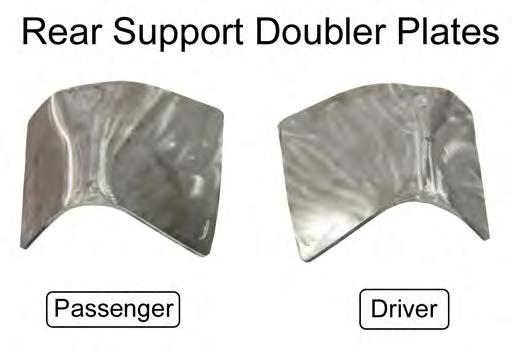
1 3430 Sacramento Dr., Unit D San Luis Obispo, CA Telephone: 805/ Fax: 805/ Roll Bar (Mm5RB-20.1 to -20.6) Recommended Center punch 1/8" pilot drill 1-3/4" Hole saw 2" Hole saw Read all instructions before beginning work. Following instructions in the proper sequence will ensure the best and easiest installation. Some steps are intended for roll bars equipped with door bars. These steps will be indicated with the words (DB ONLY), and can be skipped if door bars are not being installed. The latest version, high quality COLOR instructions are available online at Check the bottom of your installation instructions for the date and compare it to the copy available online. Installation Time (does not include welding and painting): 6 hours Tools Required T-47 Torx Bit Standard assortment of hand tools 8mm socket or wrench 10mm deep socket (door bar models only) 13mm wrench and socket 15mm wrench and socket 9/16" wrench and socket Torque wrench Drill 7/16" drill bit (more than one may be useful) Floor jack 2 jack stands (4 for door bar models) Straight-edge or long ruler Hacksaw or Wood Saw Mm5RB-20.1to20.6r1.indd 1 Preparation The vehicle must be safely supported on jack stands and have the rear wheels removed. For roll bars with the door bar option, the entire vehicle must be supported on jack stands to gain access to the plastic panel covering the fuel filter. The MM Support Brackets are shipped unpainted. We recommend painting the brackets prior to the actual installation so they don t have to be removed once correctly positioned. Unpack the roll bar and remove the supplied hardware and mounting plates/brackets. Verify that the items in the hardware list are present. Identified below are the main components of the kit: Copyright 2011 Maximum Motorsports, Inc.
2 (Following components for door bar models) Copyright 2011 Maximum Motorsports, Inc. 2 Mm5RB-20.1to20.6r1.indd


3 Interior Removal/Preparation 1. If currently installed, remove the front seats. Slide the seats forward to remove the two seat track covers. 4. Tip the seat back, to disconnect the wiring harness connectors for the air bag module and seat. Carefully pull the seats out of the car and place aside. 2. Next, remove the two rear hex nuts using a 15mm socket. 5. Disconnect the battery ground cable by using an 8mm socket. 3. Slide the seats all the way back to remove the two front hex bolts using a 13mm socket. 6. Remove the rear seat cushion. Push rearward on the two seat cushion release tabs while lifting up at the front to remove the rear cushion assembly. Mm5RB-20.1to20.6r1.indd 3 Copyright 2011 Maximum Motorsports, Inc.

 snap-in")


 push-pin retainers on each panel; one is located at the")

4 7. Remove the rear seat backrests. Using a 13mm socket, unscrew the hex bolt on the lower, outboard corner of each backrest. 10. Remove the door scuff plates. Pull up at the ends and middle of the plates to disengage the three (4) snap-in retainers. 8. Pull the release strap to pivot the backrests down and slide the backrests off of the center pivot bracket to remove them from the car. 9. Remove the T-47 Torx bolts holding the safety belts to the rocker panels. 11. Remove the rear quarter panels. There are three (3) push-pin retainers on each panel; one is located at the front of the seat bulkhead and two are at the rear seat backrest. Carefully pull the rear half of the panels inwards to disengage the snap-in retainers located below the quarter window, and then pull the panels forward. NOTE: Take care to avoid tearing the sound-deadening mat located beneath the panels. Copyright 2011 Maximum Motorsports, Inc. 4 Mm5RB-20.1to20.6r1.indd


5 13. (DB ONLY) Remove the two push-pins retaining the carpet to the rear seat bulkhead. 12. (DB ONLY) Remove both front plastic kick panels. Pull the portion closest to the firewall inboard to disengage the push-pin retainer, and then pull the panels rearward. NOTE: The passenger side panel may have an alarm switch connected to it. Be sure to remove the switch before pulling the panel out of the vehicle. 14. (DB ONLY) Pull the driver and passenger sides of the carpet up and fold them over the center console to protect it during the remaining installation. Use the provided zip-tie to hold the two halves of the carpet together. Mm5RB-20.1to20.6r1.indd 5 Copyright 2011 Maximum Motorsports, Inc.


6 NOTE: If present, disconnect the wiring harness connected to the seat belt so that the carpet can be folded over the center console. 15. Relocate the wiring harness in the area adjacent to each B-pillar. Unfasten the harness retaining clips from the vehicle and pull the harness inboard to clear the factory support brackets. If necessary, more slack can be achieved by disconnecting the harness where it plugs into each of the seatbelt retractors. 16. Unbolt and remove the two factory support brackets that connect the B-pillar to the rear seat bulkhead. Each bracket has seven 13mm hex head sized bolts and two 15mm hex head sized bolts. 17. Scrape away any excess seam sealer around the factory support bracket mounting area. NOTE: There is a release clip that must be disengaged on the inboard face of the seatbelt retractor electrical connector on some vehicles. Use a small screwdriver to pop the release clip up, away from the connector. Copyright 2011 Maximum Motorsports, Inc. 6 Mm5RB-20.1to20.6r1.indd


. 21.")
7 MM Support Bracket Installation There will be gaps due to vehicle production tolerances between the MM Support Bracket and the vehicle. These gaps must be minimized to 1/8 or less around the B-pillar mounting holes. Extra washers are provided to accomplish this task. Use the following steps to correctly position the driver and passenger side brackets. Below is a picture identifying the individual holes: 20. Check the gap between the bracket and the vehicle at H8. Use the provided 3/8 G8 washers to close the gap to 1/8 or less. When satisfied, insert one of the factory mounting bolts into the hole to prevent the washers from being dislodged. NOTE: It may be helpful to tape the washers to the end of a small screwdriver to aid in sliding them into position. 18. Starting on the driver side, set the MM Support Bracket into position. The bracket should be resting against the b-pillar and the front of the rear seat bulkhead. 19. Check the gap between the bracket and the vehicle at Hole 2 (H2). Use the provided 3/8 G8 washers to close the gap to 1/8 or less. When satisfied, insert one of the factory mounting bolts into the hole to prevent the washers from being dislodged. 21. Install the remaining mounting bolts into the Support Bracket and tighten them by hand. Take note that H6 and H7 use the larger, 15mm hex head bolts. NOTE: Small gaps are acceptable, as the vehicle and the MM Support Bracket will conform to each other as the mounting bolts are tightened. 22. Using a wrench, tighten, but do not torque, all of the bolts in numerical order from H1 to H9 so that the bracket can be properly seated against the vehicle. 23. Following the same numerical order, torque the 13mm hex size bolts to 17lb-ft (23Nm) and the 15mm hex size bolts to 48lb-ft (65Nm). 24. Repeat Steps for the passenger side bracket. Mm5RB-20.1to20.6r1.indd 7 Copyright 2011 Maximum Motorsports, Inc.


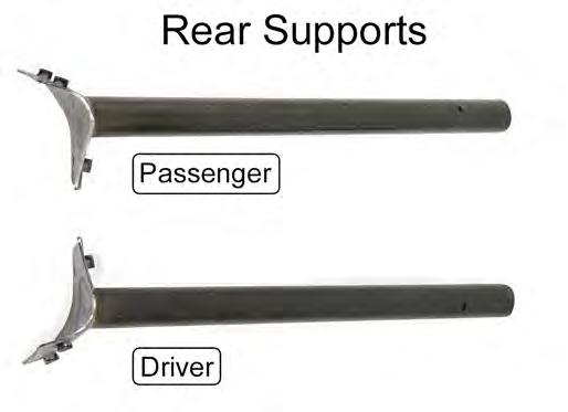
8 Main Hoop Installation 25. Slide the Driver and Passenger Side Rear Supports onto the Rear Support Spuds and secure them with the provided 3/8 x 2 ¼ long bolts and 3/8 Nylock nuts. Only hand tighten, do NOT torque them yet. 28. Remove the sound deadening material within the outline using a chisel or other scraping device. Once done, reinstall the Roll Bar into the vehicle. 26. Place the Roll Bar into the vehicle by tilting the hoop forward and passing it through the passenger side door. Once the Roll Bar is in the vehicle, tilt it rearwards and place it onto the MM Support Brackets and the Rear Support Mounting Pads on the inner corner of each rear wheel well. NOTE: Make sure that the hoop is as far forward in the vehicle as possible when tilting in rearwards into position. By keeping the hoop forward, it will allow the rear support pads to clear the plastic trim panels on the upper half of the b-pillars. 29. Loosely secure the hoop to the MM Support Brackets using the provided 3/8 G8 washers and 3/8-16 x 1 G5 bolts. 27. Trace an outline of the Rear Support Mounting Pads onto the driver and passenger side wheel well, and then remove the roll bar from the vehicle. Copyright 2011 Maximum Motorsports, Inc. 8 Mm5RB-20.1to20.6r1.indd
 Slide the Door Bars onto the Door Bar Spuds on the Main Hoop.")


 Center the Roll Bar in the vehicle by closing the doors and checking to see if both Door Bars are touching the door panel near the Door Bar Spuds.")
9 NOTE: In some cases, it may be necessary to enlarge the holes in the Main Hoop Mounting Pads to provide clearance for the mounting bolts. 32. Temporarily tighten the bolts that secure the hoop to the MM Support Brackets. 30. (DB ONLY) Slide the Door Bars onto the Door Bar Spuds on the Main Hoop. Use two of the provided 3/8-16 x 2 ¼ long bolts and 3/8-16 Nylock nuts to loosely secure the bars in place. The Door Bar Mounting Pads should touch the rocker panel and rest flat on the raised bosses on the floor. 33. With both Rear Support Mounting Pads in their proper position (resting firmly against each rear wheel well), tighten the two bolts holding the Rear Supports to the Main Hoop so that the Rear Supports can NOT move. NOTE: If there is excess sound deadening material beneath the Door Bar Mounting Pad, it will not rest flat against the floor pan. Use a chisel or other scraping device to remove the excess material as needed. 31. (DB ONLY) Center the Roll Bar in the vehicle by closing the doors and checking to see if both Door Bars are touching the door panel near the Door Bar Spuds. If they are both touching, the Roll Bar is centered. If they do not touch, reposition the hoop so that the gaps between each Door Bar and each door panel are equal on each side of the car. NOTE: Make sure to double check that the Door Bar Mounting Pads are touching the rocker panel and resting flat on the floor once the doors have been closed. Mm5RB-20.1to20.6r1.indd 9 Copyright 2011 Maximum Motorsports, Inc.


10 34. Mark the position of the four mounting holes in each Rear Support Mounting Pad onto the wheel well using a center punch. 35. (DB ONLY) Mark the position of the four mounting holes in each Door Bar Mounting Pad onto the floor pan using a center punch. 37. Hold the Driver Side Rear Support Doubler Plate up into position against the bottom of the wheel well, centered under the four mounting holes. NOTE: One of the mounting holes is located beneath the Door Bar Tubing on each pad. Use a marker or small metal scribe to mark the hole location. 36. Remove the Roll Bar from the vehicle and drill the four holes marked on each wheel well out to a 7/16 diameter. Use ~1/8 diameter pilot drill to start the holes. 38. With the doubler plate held in position, have someone mark the location of the mounting holes from the inside of the vehicle using a center punch or marker. Copyright 2011 Maximum Motorsports, Inc. 10 Mm5RB-20.1to20.6r1.indd


11 39. Drill out the holes in the doubler plates to 7/16 diameter and set them aside for later installation. 42. (DB ONLY) CAREFULLY drill down from above, the four holes marked for each Door Bar Mounting Pad out to a 7/16 diameter. 40. Repeat Steps for the Passenger Side Rear Support Doubler Plate. NOTE: Skip to Step 43 if you do NOT have door bars with your roll bar NOTE: There ARE fuel and brake lines directly beneath the driver side Door Bar Mounting Pad. Place the Door Bar Doubler Plate between the underside of the floor pan and the lines (as a shield) when drilling to prevent puncturing the lines. Door Bar Mounting Holes 41. (DB ONLY) Remove the plastic trim panel on the underside of the floor pan, beneath the driver seat, that protects the fuel/brake lines and fuel filter. Use a 10mm deep socket to remove the two hex nuts and two 10mm hex head bolts, and pliers to remove the one push-pin that secures the panel. Mm5RB-20.1to20.6r1.indd 11 Copyright 2011 Maximum Motorsports, Inc.


12 Plastic Quarter Panel Modifications The plastic quarter panels have to be modified to allow the Roll Bar and Rear Supports to pass through. Use the following steps to properly trim the panels. 43. Using a straight edge, mark a line down the plastic quarter panel that is aligned with the center of the vertical groove, towards the front of the armrest. If no groove is present, mark a line parallel to the front of the panel, approximately 4.75 rearward. 45. Using a 1-3/4 hole saw, cut a hole in the center of the flat, 3/8 forward of the marked line. 44. At the bottom of the quarter panel, extend the line across the horizontal flat. Add a mark about 3/8 forward of the line, centered side-to-side on the flat section. Copyright 2011 Maximum Motorsports, Inc. 12 Mm5RB-20.1to20.6r1.indd


13 46. Cut the plastic quarter panel into two pieces, along the line that was drawn, using a wood saw or other cutting device. 51. Set the Roll Bar back in its mounting position and slide the PVC tube down until it contacts the plastic quarter panel. Rotate the PVC tube so that the end is parallel to the face of the panel. 47. Repeat for both sides. 48. Install the rear half of the driver side plastic quarter panel. 49. Remove the Driver Side Rear Support from the Main Hoop and place the hoop into the vehicle. 52. Use a marker to trace around the PVC tube, the location where the Rear Support will pass through the plastic panel. 50. Place the supplied PVC tube onto the Driver Side Rear Support Spud. 53. Remove the rear half of the plastic panel from the vehicle and hole saw through the location marked for the Rear Support. Use a 2 hole saw if available, if not a 1-3/4 hole saw can be used and the opening can be filed out larger. Mm5RB-20.1to20.6r1.indd 13 Copyright 2011 Maximum Motorsports, Inc.


14 55. Repeat Steps for the passenger side of the vehicle with the Driver Side Rear Support installed and the Passenger Side Rear Support removed. Welding the Rear Supports 54. Cut a vertical line from the bottom of the plastic panel up to the rearward edge of the hole. This will allow the panel to be slid onto the rear support during installation. Use sandpaper or a file to remove any burrs from the edge of the plastic panel. 56. With both Rear Supports attached, place the Roll Bar back into its mounting position and verify that all of the holes for the Main Hoop and Rear Support Mounting Pads line up with the holes in the vehicle. We highly recommend inserting all of the mounting bolts to guarantee that the holes line up. 57. Tighten the bolts holding the Rear Supports to the Rear Support Spuds so that the supports cannot move. 58. Remove the Roll Bar from the vehicle, with the Rear Supports firmly attached. 59. Have a certified/professional welder weld the Rear Supports to the Main Hoop. NOTE: To ensure structural integrity and safety, make sure the Rear Supports are welded to the Main Hoop, and not simply to the Rear Support Spuds. The Rear Support Spuds are merely a locating device to aid installation; they are NOT a structural part of the Roll Bar. NOTE: If desired, remove the bolts from the Rear Supports and plug weld the holes shut once the supports have been welded to the main hoop. Copyright 2011 Maximum Motorsports, Inc. 14 Mm5RB-20.1to20.6r1.indd


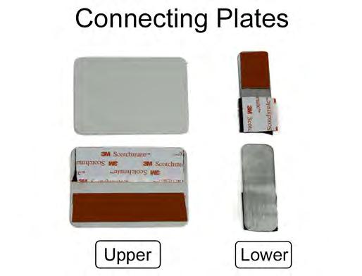
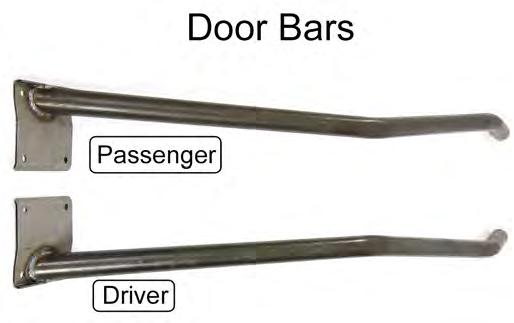
15 Painting the Roll Bar 60. We recommend painting or powder coating the roll bar and its components to protect them from rust. NOTE: If the barrel shaped portion of the door bar mounting spuds are painted or powder coated, the INNER DIAMETER OF THE DOOR BAR MAY NEED TO BE ENLARGED slightly so that the Door Bar may slide over the spud. Use a round file or sandpaper to help enlarge the inner diameter. Quarter Panel Connecting Plates 61. Clean the back of both halves the plastic quarter panels along the cut line at the large flat area near the top, and the bottom flat area. Use acetone or isopropyl alcohol to remove any grease or mold release. NOTE: Hold the Connecting Plates in position and use a scribe to mark the outline of the Connecting Plates onto the panels. Only this area needs to be cleaned. 62. Open ONE of the provided 3M Adhesion Promoter applicator packets and coat the areas cleaned in the previous step using the foam applicator. Once the areas have been coated, allow the adhesion promoter to dry for 1-2 minutes. NOTE: The temperature must be 70 F or higher for the best results. 63. Remove the plastic backing from the foam tape strips on the Connecting Plates. Adhere the Connecting Plates to the upper and lower prepped areas of the rear half of each quarter panel. Press down firmly for a few seconds on each Connecting Plate to help the adhesive stick. 64. Repeat Steps for the forward half of the plastic panels using the remaining 3M Adhesion Promoter packet. 65. Remove the plastic backing from the Velcro strips and align the two pieces of the quarter panel together. Once aligned, press down firmly for a few seconds on each Connecting Plate to help the adhesive stick. 66. Let the panels sit for about 30 minutes before any further handling. If the temperature is below 70 F, allow extra time for the adhesive to cure, or place the panels indoors. 67. Separate the front and rear halves of the quarter panels by CAREFULLY pulling them apart at the Velcro. Mm5RB-20.1to20.6r1.indd 15 Copyright 2011 Maximum Motorsports, Inc.
 to protect them from scratches during installation. 72.")


 push-pin retainers on each panel located at the rear seat backrest. Be sure to engage the snap-in retainers located below the quarter window. 75.")
16 Final Installation NOTE: Have at least two people help when setting the Roll Bar into its final position, and be patient. 68. Wrap the Rear Support tubes with something (such as tape, paper, or cloth) to protect them from scratches during installation. 72. Reinstall all the mounting hardware for the Main Hoop and Rear Supports before tightening any of the bolts. The Main Hoop uses 3/8-16 x 1 long bolts with a 3/8 G8 washer under the bolt head. The Rear Supports use 3/8-16 x 3/4 long bolts and 3/8 G8 washers beneath the bolt heads. 69. Place the Roll Bar into the vehicle so that the Rear Support Mounting Pads are resting on/near the MM Support Brackets and the Main Hoop Pads are on the floor pan. 70. Install the rear half of the plastic quarter panels onto each of the Rear Supports by carefully spreading the vertical slit until the panels can slide onto the Rear Supports. 71. Lift the Roll Bar, along with the plastic panels, into position. 73. Torque the bolts to 33 lb-ft. 74. Attach the back half of the rear plastic quarter panels to the vehicle. There are two (2) push-pin retainers on each panel located at the rear seat backrest. Be sure to engage the snap-in retainers located below the quarter window. 75. Place the wiring harness back into the stock location and reconnect the harness to the seat belt retractors (if disconnect in Step 14). 76. (DB ONLY) Unfold the carpet from the center console and place it back into position. Reinstall the two push-pins located on the rear seat bulkhead. Copyright 2011 Maximum Motorsports, Inc. 16 Mm5RB-20.1to20.6r1.indd

 Remove the Door Bars. 83. Reconnect the battery. 84. Reinstall the front seats; installation is the opposite of removal in Step 1. Torque the bolts and nuts to 35 lb-ft (48Nm). 85.")
17 77. Attach the front half of the rear plastic quarter panels. Install the 1 push-pin retainer to secure each quarter panel to the rear seat bulkhead. NOTE: Installation is easier if the panel is correctly positioned before the Velcro is stuck together. To do this, cover the Velcro strips with paper (temporarily secure the paper to the panel using tape); position the panel; then remove the paper. Press the two Velcro strip halves together. 82. (DB ONLY) Remove the Door Bars. 83. Reconnect the battery. 84. Reinstall the front seats; installation is the opposite of removal in Step 1. Torque the bolts and nuts to 35 lb-ft (48Nm). 85. (DB ONLY) Install the Door Bars using 3/8-16 x 2 ¼ long bolts and 3/8-16 Nylock nuts. Do not tighten the bolts yet. 86. (DB ONLY) Secure the Door Bar Doubler Plates using the following hardware: Use 3/8-16 x 1" long bolts, 3/8-16 Nylock nuts, and 3/8 G8 washers beneath the bolt heads and nuts for the two outboard mounting holes. Use 3/8-16 x 1-1/4 long bolts, along with the provided Half-Round Spacers, 3/8-16 Nylock nuts, and 3/8 G8 washers beneath the bolt heads and nuts for the two inboard mounting holes. 78. Reinstall the safety belts to the rocker panels and torque the T-47 Torx bolts to 30 lb-ft (40Nm). 79. Reinstall the rear seat backrest cushions. Torque the two 13mm hex head backrest bolts to 17 lb-ft (23Nm). NOTE: MM Roll Bars with a Fixed Harness Mount and/or a Diagonal Brace do not allow the rear seats to fold down. Make sure to install the seat backrest cushions in the upright position before tightening the mounting bolts. 80. Reinstall the rear lower seat cushion. 87. (DB ONLY) Torque the entire Door Bar mounting 81. (DB ONLY) Temporarily install the Door Bars hardware to 33 lb-ft. onto the Door Bar Spuds and trim a hole in the carpet for each Door Bar. Mm5RB-20.1to20.6r1.indd 17 Copyright 2011 Maximum Motorsports, Inc.
 to avoid any contact with the bolt heads. This can be done by bending them slightly.")
18 88. (DB ONLY) The outboard brake line will touch the heads of the Door Bar mounting hardware. Wrap the provided spiral wrap onto the brake line where it makes contact with the mounting hardware. Use the remaining two Zip-ties to secure the wrap to the line. NOTE: We recommend repositioning the line(s) to avoid any contact with the bolt heads. This can be done by bending them slightly. Models with door bars include: 1 Roll Bar 2 Rear Support (D & P) 2 Door Bar (D & P) 2 Support Bracket (D & P) 2 Rear Support Doubler Plate (D & P) 2 Door Bar Mounting Plate 1 PVC Template 2 Upper Connecting Plate 2 Lower Connecting Plate 4 Half Round Washer 8 3/8-16 x 3/4 Bolt 12 3/8-16 x 1 Bolt 4 3/8-16 x 1-1/4 Bolt 4 3/8-16 x 2-1/4 Bolt 60 3/8 G8 Washer 12 3/8-16 Nylock Nut 2 3M Adhesion Promoter Packet 1 Spiral Wrap (6 Long) 3 Zip-tie Models without door bars include: 89. (DB ONLY) Install the plastic trim panel removed in Step 41 that protects the fuel/brake lines and fuel filter. Torque the 10mm hex head bolts and nuts to 5 lb-ft (7Nm). 90. (DB ONLY) Set the forward half of the carpet back into position. 91. (DB ONLY) Install the plastic kick panels and secure each one with a plastic push-pin. NOTE: Reinstall the alarm switch into the passenger side kick panel if it was removed in Step Install the door scuff plates. 93. Reinstall the rear wheels and safely lower the vehicle to the ground. Torque the lug nuts to the manufacturers recommend value. 1 Roll Bar 2 Rear Support (D & P) 2 Support Bracket (D & P) 2 Rear Support Doubler Plate (D & P) 1 PVC Template 2 Upper Connecting Plate 2 Lower Connecting Plate 8 3/8-16 x 3/4 Bolt 8 3/8-16 x 1 Bolt 2 3/8-16 x 2-1/4 Bolt 44 3/8 G8 Washer 2 3/8-16 Nylock Nut 2 3M Adhesion Promoter Packet 1 Zip-tie NOTE: Roll bar padding must be installed on any areas of the Roll Bar that the vehicle occupants may possibly contact during an accident. This includes any parts of the Roll Bar that the occupants hands, arms, legs, and feet may contact, as well as the head. Copyright 2011 Maximum Motorsports, Inc. 18 Mm5RB-20.1to20.6r1.indd
2005+ Drag Race Roll Bar (Mm5RB-20)
") 3430 Sacramento Dr., Unit D San Luis Obispo, CA 93401 Telephone: 805/544-8748 Fax: 805/544-8645 www.maximummotorsports.com 2005+ Drag Race Roll Bar (Mm5RB-20) Note that the NHRA DOES allow the door bars
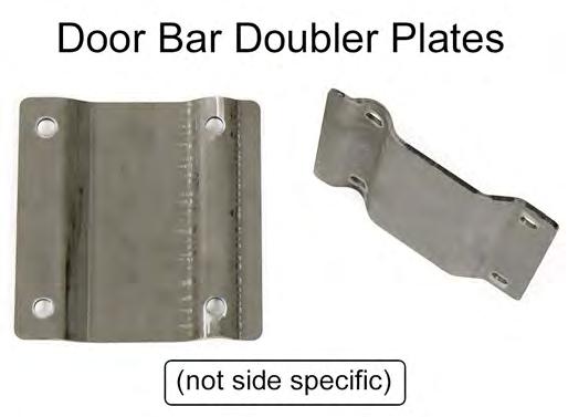
3430 Sacramento Dr., Unit D San Luis Obispo, CA 93401 Telephone: 805/544-8748 Fax: 805/544-8645 www.maximummotorsports.com 2005+ Drag Race Roll Bar (Mm5RB-20) Note that the NHRA DOES allow the door bars
Roll Bar (MMRB-6.1 to -6.7)
") 3430 Sacramento Dr., Unit D San Luis Obispo, CA 93401 Telephone: 805/544-8748 Fax: 805/544-8645 www.maximummotorsports.com 1994-04 Roll Bar (MMRB-6.1 to -6.7) NOTE: These instructions cover Roll Bars with
3430 Sacramento Dr., Unit D San Luis Obispo, CA 93401 Telephone: 805/544-8748 Fax: 805/544-8645 www.maximummotorsports.com 1994-04 Roll Bar (MMRB-6.1 to -6.7) NOTE: These instructions cover Roll Bars with
Drag Race Roll Bar (MMRB-6, -7)
") 3430 Sacramento Dr., Unit D San Luis Obispo, CA 93401 Telephone: 805/544-8748 Fax: 805/544-8645 www.maximummotorsports.com 1994-04 Drag Race Roll Bar (MMRB-6, -7) The Maximum Motorsports 6-point Drag Race
3430 Sacramento Dr., Unit D San Luis Obispo, CA 93401 Telephone: 805/544-8748 Fax: 805/544-8645 www.maximummotorsports.com 1994-04 Drag Race Roll Bar (MMRB-6, -7) The Maximum Motorsports 6-point Drag Race
Convertible MM Roll Bar (MMRB-10.1 to -10.7)
") 3430 Sacramento Dr., Unit D San Luis Obispo, CA 93401 Telephone: 805/544-8748 Fax: 805/544-8645 www.maximummotorsports.com 1983-93 Convertible MM Roll Bar (MMRB-10.1 to -10.7) The Maximum Motorsports RB-10.1
3430 Sacramento Dr., Unit D San Luis Obispo, CA 93401 Telephone: 805/544-8748 Fax: 805/544-8645 www.maximummotorsports.com 1983-93 Convertible MM Roll Bar (MMRB-10.1 to -10.7) The Maximum Motorsports RB-10.1
Roll Bar (MMRB-1.1 to 1.7)
") 3430 Sacramento Dr., Unit D San Luis Obispo, CA 93401 Telephone: 805/544-8748 Fax: 805/544-8645 www.maximummotorsports.com 1979-93 Roll Bar (MMRB-1.1 to 1.7) The Maximum Motorsports RB-1.1 to -1.7 Roll
3430 Sacramento Dr., Unit D San Luis Obispo, CA 93401 Telephone: 805/544-8748 Fax: 805/544-8645 www.maximummotorsports.com 1979-93 Roll Bar (MMRB-1.1 to 1.7) The Maximum Motorsports RB-1.1 to -1.7 Roll
Deuce/Ace Installation Instructions
 HARDWARE KIT: Upper Mounting Plate: 2-7/16" (11mm) X 3.5" bolts 2-7/16" flange nuts 2-2" spacers 2-7/16" trim cap mounting washers 2 - plastic trim caps TOOLS NEEDED: safety glasses wrenches 16mm or 5/8"
Classic Light Bar Mustang
 Classic Light Bar 2005-2012 Mustang Note: Read installation instructions before starting. Component List: 1 Light Bar Part #110000 1 Driver Side Bracket w/set Screw Part #115003 1 Passenger Side Bracket
INSTALLATION INSTRUCTIONS
 INSTALLATION INSTRUCTIONS Document# 19-0038 2004+ Lotus Elise (Series 2) Rear Clamshell Removal Kit Safely support the vehicle. This is a two-person job. Allow 1 to 2 hours for initial disassembly. Have
Mustang Classic LightBar Instructions
 1994-2004 Mustang Classic LightBar Instructions Note: Read installation instructions before starting. Component List: 1 LightBar 4 Poly Plugs 4 LightBar Bolts 4 LightBar Washers 2 LightBar Rivets 2 Light
MM Tubular K-Member, (Mm5KM-7)
") 3430 Sacramento Dr., Unit D San Luis Obispo, CA 93401 Telephone: 805/544-8748 Fax: 805/544-8645 www.maximummotorsports.com MM Tubular K-Member, 2005-14 (Mm5KM-7) This Kit Contains Congratulations on purchasing
3430 Sacramento Dr., Unit D San Luis Obispo, CA 93401 Telephone: 805/544-8748 Fax: 805/544-8645 www.maximummotorsports.com MM Tubular K-Member, 2005-14 (Mm5KM-7) This Kit Contains Congratulations on purchasing
IRS Racing Brake Kit (MMBAK-15, -16)
") 3430 Sacramento Dr., Unit D San Luis Obispo, CA 93401 Telephone: 805/544-8748 Fax: 805/544-8645 www.maximummotorsports.com IRS Racing Brake Kit (MMBAK-15, -16) Floating rotors (MMBAK-16 ONLY) can move
3430 Sacramento Dr., Unit D San Luis Obispo, CA 93401 Telephone: 805/544-8748 Fax: 805/544-8645 www.maximummotorsports.com IRS Racing Brake Kit (MMBAK-15, -16) Floating rotors (MMBAK-16 ONLY) can move
2015 Mustang Lightbar (All Models) CDC#
 CDC#") 2015 Mustang Lightbar (All Models) CDC# 1511-7000-01 Components: 1 CDC Lightbar Note: READ instructions before starting installation!!! CDC Part# Driver side bracket 0511-6001-05 Passenger side bracket
2015 Mustang Lightbar (All Models) CDC# 1511-7000-01 Components: 1 CDC Lightbar Note: READ instructions before starting installation!!! CDC Part# Driver side bracket 0511-6001-05 Passenger side bracket
RPM Rollbar Installation Instructions Ford Mustang 05-11
 RPM Rollbar Installation Instructions Ford Mustang 05-11 IMPORTANT READ BEFORE STARTING INSTALLATION Check for backing plate clearance between the undercarriage and fuel lines directly below area where
MM Caster/Camber Plates, (MMCC7989)
") 3430 Sacramento Dr., Unit D San Luis Obispo, CA 93401 Telephone: 805/544-8748 Fax: 805/544-8645 www.maximummotorsports.com MM Caster/Camber Plates, 1979-89 (MMCC7989) IMPORTANT: The bearing used in our
3430 Sacramento Dr., Unit D San Luis Obispo, CA 93401 Telephone: 805/544-8748 Fax: 805/544-8645 www.maximummotorsports.com MM Caster/Camber Plates, 1979-89 (MMCC7989) IMPORTANT: The bearing used in our
US Patent You will find many features that set our Caster/Camber Plates apart from the rest.
 3430 Sacramento Dr., Unit D San Luis Obispo, CA 93401 Telephone: 805/544-8748 Fax: 805/544-8645 www.maximummotorsports.com US Patent 6485223 Read all instructions before beginning work. Following instructions
Severe Duty Oil Filter Relocation Kit (OC-9)
") 3430 Sacramento Dr., Unit D San Luis Obispo, CA 93401 Telephone: 805/544-8748 Fax: 805/544-8645 www.maximummotorsports.com Severe Duty Oil Filter Relocation Kit (OC-9) Filter Mount Installation 4. Remove
3430 Sacramento Dr., Unit D San Luis Obispo, CA 93401 Telephone: 805/544-8748 Fax: 805/544-8645 www.maximummotorsports.com Severe Duty Oil Filter Relocation Kit (OC-9) Filter Mount Installation 4. Remove
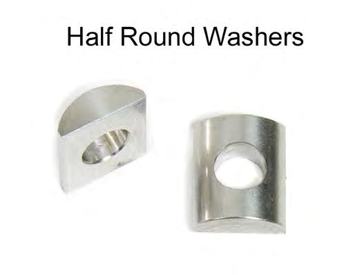
INSTALLATION INSTRUCTIONS
 Rear Vision System Tailgate Emblem Camera Mirror Display 2009-Current Ford F-150 and 2010-Current Super Duty (Kit part number 1008-9527) Kit Contents: Mirror Tailgate Emblem Mount with Camera Interior
4.6L Oil Filter Relocation Kit, (OC-7)
") 3430 Sacramento Dr., Unit D San Luis Obispo, CA 93401 Telephone: 805/544-8748 Fax: 805/544-8645 www.maximummotorsports.com 4.6L Oil Filter Relocation Kit, 2003-04 (OC-7) Filter Mount Installation 4. Remove
3430 Sacramento Dr., Unit D San Luis Obispo, CA 93401 Telephone: 805/544-8748 Fax: 805/544-8645 www.maximummotorsports.com 4.6L Oil Filter Relocation Kit, 2003-04 (OC-7) Filter Mount Installation 4. Remove
991 ROLL BAR INSTALLATION:
 991 ROLL BAR INSTALLATION: We highly recommend CMS roll bars be fitted by shops with experience in installing roll bars. 1. Move power seats to a location where the four bolts can be removed and remove
MUSTANG TIGER CAGE INSTRUCTIONS MANUAL PAGE 1
 2005-2011 MUSTANG TIGER CAGE INSTRUCTIONS MANUAL PAGE 1 Thank you for purchasing our 2005-2011 Mustang Tiger Cage. Please read through all of the instructions first and then start installing the kit. We
INSTALLATION INSTRUCTIONS 97 FORD EXPEDITION
 INSTALLATION INSTRUCTIONS 97 FORD EXPEDITION 1. Read the instructions completely and carefully before you begin. Check the kit for proper contents (refer to the part s list and the picture diagrams). Before
Standard Duty Oil Filter Relocation Kit (OC-8)
") 3430 Sacramento Dr., Unit D San Luis Obispo, CA 93401 Telephone: 805/544-8748 Fax: 805/544-8645 www.maximummotorsports.com Standard Duty Oil Filter Relocation Kit (OC-8) Filter Mount Installation 4. Remove
3430 Sacramento Dr., Unit D San Luis Obispo, CA 93401 Telephone: 805/544-8748 Fax: 805/544-8645 www.maximummotorsports.com Standard Duty Oil Filter Relocation Kit (OC-8) Filter Mount Installation 4. Remove
INSTALLATION INSTRUCTIONS
 Rear Vision System Liftgate Emblem Camera Mirror Display 2009-2012 Ford Flex (Kit part number 1008-9527) Kit Contents: Mirror Liftgate Emblem Mount with Camera Interior (shorter) Harness Chassis (longer)
Installation Instructions
 Installation Instructions Jeep JK Unlimited (2007 Present) Mounting Bracket and Air Line System Kit for ARB On-Board Twin Air Compressor (CKMTA12) Made in the USA Kit Contents: 1 Bracket for ARB Compressor
Ground Effects, P/N: (V6), (V8)
, (V8)") , P/N: 92248596 (V6), 92248560 (V8) 3. Open trunk and remove 3 scrivets per side. Retain. Remove LH and RH tail lamp access cover. Retain. Refer to Figure 1. NOTE: Installation is made easier with the
, P/N: 92248596 (V6), 92248560 (V8) 3. Open trunk and remove 3 scrivets per side. Retain. Remove LH and RH tail lamp access cover. Retain. Refer to Figure 1. NOTE: Installation is made easier with the
Front seats. j a t CAUTION! Before beginning repairs on the electrical system: Obtain the anti-theft radio security code. Switch the ignition off.
 j a t Front seats 72-1 CAUTION! Before beginning repairs on the electrical system: Obtain the anti-theft radio security code. Switch the ignition off. Search Advanced Search Disconnect the battery Ground
Roush Side Rocker Panel Splitters (10-13 All)
") Required tools: Jack stands (2) Floor jack (1 is required but 2 is preferred) Pliers Small Phillips screw driver Drill ¼ Drill bit T15 Torx bit (for some models of vehicle) Hacksaw (for some models of
Required tools: Jack stands (2) Floor jack (1 is required but 2 is preferred) Pliers Small Phillips screw driver Drill ¼ Drill bit T15 Torx bit (for some models of vehicle) Hacksaw (for some models of
MM Brake Line Kit for Fox-IRS Swap (MMBAK-21)
") 3430 Sacramento Dr., Unit D San Luis Obispo, CA 93401 Telephone: 805/544-8748 Fax: 805/544-8645 www.maximummotorsports.com MM Brake Line Kit for Fox-IRS Swap (MMBAK-21) Supplemental Installation Notes
3430 Sacramento Dr., Unit D San Luis Obispo, CA 93401 Telephone: 805/544-8748 Fax: 805/544-8645 www.maximummotorsports.com MM Brake Line Kit for Fox-IRS Swap (MMBAK-21) Supplemental Installation Notes
Detroit Speed, Inc. Rear QUADRAlink Conversion Kit Camaro/Firebird P/N:
 Detroit Speed, Inc. Rear QUADRAlink Conversion Kit 1982-92 Camaro/Firebird P/N: 041721 The Detroit Speed Inc. QUADRAlink Conversion Kit, eliminates the factory torque arm configuration. It features no-compromise
GENUINE PARTS INSTALLATION INSTRUCTIONS
 GENUINE PARTS INSTALLATION INSTRUCTIONS DESCRIPTION: APPLICATION: PART NUMBER: KIT-CARBON FIBER REAR SPOILER INFINITI Q50 T99J1 J5000 KIT CONTENTS: Item A B C D Qty. 1 4 1 1 Part Description Spoiler Assembly
JEEP Wrangler JK/JKU Swing-A-Way Tire Carrier/RotoPpax WARNINGS/CAUTIONS NOTE. INSTALLATION INSTRUCTIONS 2 Door Models 85209
 JEEP Wrangler JK/JKU Swing-A-Way Tire Carrier/RotoPpax 2007-2017 INSTALLATION INSTRUCTIONS Item Kit No. 2 Door Models 85209 4 Door Models 85209 WARNINGS/CAUTIONS These instructions are for both the can
INSTALLATION INSTRUCTIONS
 INSTALLATION INSTRUCTIONS Accessory Application Publications No. SYSTEM S2000 AII 26324 Issue Date OCT 2004 PARTS LIST Headrest Speaker System P/N 08A54-S2A-100 3 Small wire ties 2 Headrest speakers 9
Standard Duty Oil Filter Relocation Kit (OC-3)
") 3430 Sacramento Dr., Unit D San Luis Obispo, CA 93401 Telephone: 805/544-8748 Fax: 805/544-8645 www.maximummotorsports.com Standard Duty Oil Filter Relocation Kit (OC-3) Read all of the instructions before
3430 Sacramento Dr., Unit D San Luis Obispo, CA 93401 Telephone: 805/544-8748 Fax: 805/544-8645 www.maximummotorsports.com Standard Duty Oil Filter Relocation Kit (OC-3) Read all of the instructions before
Mustang Shaker
 2005-2009 Mustang Shaker CDC #110050 ( 05/ 06) or 0711-7000-01 ( 07/ 09) Component Check List: Quantity/Description Part # CDC Installer 1 - Engine Cover Assembly 114050 1 - Aluminum Shaker Scoop 183020
PPM-5203 TJ/LJ FRONT CAGE KIT Version 1.1
 POLY PERFORMANCE MFG. 870 INDUSTRIAL WAY, SAN LUIS OBISPO, CA (805) 242-0397 PPM-5203 TJ/LJ FRONT CAGE KIT Version 1.1 GENERAL NOTES: These instructions are also available on our website; www.synergysuspension.com.
2. Remove front wheels.
 Read all instructions before beginning work. Following instructions in the proper sequence will ensure the best and easiest installation. Thank you for purchasing Maximum Motorsports Caster/Camber Plates.
C15C C15C. Page 1 of 20
 2 x Lid Front Hinge 1135 8 x M8 Bolt 8 x M8 Washer (3mm Thick) 4 x M6 Large washers 4 x M6 Spring washers 4 x M6 x 40mm Bolts 6 x M6 20mm Bolts 6 x M6 Washers 20 x Screws 2 x Lid mount gas strut bracket
Before starting installation
 Before starting installation The load rating for these tire-can/tire carriers is a MAXIMUM of 175 lbs. Please be aware that some tire and wheel combinations along with gas cans and hi-lift jacks can exceed
MM Panhard Bar, Mustang (MMPBA)
") 3430 Sacramento Dr., Unit D San Luis Obispo, CA 93401 Telephone: 805/544-8748 Fax: 805/544-8645 www.maximummotorsports.com MM Panhard Bar, 1979-98 Mustang (MMPBA) Important Note for Customers with Baer
3430 Sacramento Dr., Unit D San Luis Obispo, CA 93401 Telephone: 805/544-8748 Fax: 805/544-8645 www.maximummotorsports.com MM Panhard Bar, 1979-98 Mustang (MMPBA) Important Note for Customers with Baer
Installation Instructions
 Installation Instructions Jeep JK 2-Door (2011 Present) Mounting Bracket and Air Line System Kit for ARB On-Board Twin Air Compressor (CKMTA12) Made in the USA Kit Contents: 1 Flat Bracket 1 Formed Bracket
2010 Mustang V6 Shaker CDC #
 - - Incomplete 2010 Mustang V6 Shaker CDC # 1011-7002-01 Component Check List: Quantity/Description Part # Engine Cover Assembly 1011-6000-01 1 Engine Cover w/ Upper Air Tube 0511-2100-01 1 Aluminum Shaker
YARIS 4-DOOR 2007 INTERIOR LIGHT UPGRADE
 Document # 3999 4/26/06 4-DOOR 2007 INTERIOR LIGHT UPGRADE Preparation Part Number: 00016-52060 Code: IL1 Kit Contents Item # Quantity Reqd. Description 1 1 12 Light Guide 2 1 7 Light Guide 3 1 Hardware
INSTALLATION INSTRUCTIONS
 INSTALLATION INSTRUCTIONS Accessory S P/N 08V67-SJC-101 Application 2012 RIDGELINE Publications No. AII 12006 Issue Date NOV 2011 PARTS LIST Back-up sensor harness 3 Wire ties with small clips (2 Not used)
INSTALLATION INSTRUCTIONS
 Rear Vision System Tailgate Emblem Camera Aftermarket Display 2009-Current Ford F-150 and 2010-Current Super Duty (Kit part number 1008-6509) Kit Contents: Tailgate Emblem Mount with Camera Chassis Harness
INSTALLATION INSTRUCTIONS
 INSTALLATION INSTRUCTIONS Accessory S P/N 08V67-SJC-101 Application 2010 RIDGELINE Publications No. AII 42117 Issue Date AUG 2009 PARTS LIST Back-up sensor harness 3 Wire ties with small clip (2 Not used)
TIP-OUT GLASS WINDSHIELD KIT
 TIP-OUT GLASS WINDSHIELD KIT P/N 2881108 APPLICATION Verify accessory fitment at Polaris.com. BEFORE YOU BEGIN Read these instructions and check to be sure all parts and tools are accounted for. Please
INSTALLATION INSTRUCTIONS
 INSTALLATION INSTRUCTIONS Accessory Application Publications No. CD CHANGER ATTACHMENT KIT 2005 CIVIC SI AII 27936 Issue Date AUG 2004 PARTS LIST CD Changer Attachment Kit (sold separately): P/N 08B26-S5T-100
INSTALLATION INSTRUCTIONS
 INSTALLATION INSTRUCTIONS Accessory Application Publications No. AII 27336 ODYSSEY Issue Date SEP 2004 PARTS LIST 15 Black wire ties Backup Sensor Attachment Kit P/N 08V67-SHJ-100A Backup sensor control
Hard Bar Sport, M1/M2 Hard Core Hardtop, M2 Sport, and Xtreme Installation Instructions
 HARDWARE KIT: Hard Bar Sport, M1/M2 Hard Core Shoulder Harness Guide Relocation Assemblies: 2-3/8" X 1" grade 8 bolts 4-3/8" flat washers 2-3/8" lock nuts 2 - brass bushings 2 - plastic trim caps 2-3/8"
INSTALLATION INSTRUCTIONS JEEP 2011-UP JK SECURITY FULL CONSOLE #274
 INSTALLATION INSTRUCTIONS JEEP 2011-UP JK SECURITY FULL CONSOLE #274 PARTS CHECKLIST Tuffy Console #9 Left Front Mounting Bracket #10 Right Front Mounting Bracket #11 Electronics mounting bracket #12 Divider
TOYOTA FJ CRUISER 2007 AUXILIARY LIGHTS Preparation
 TOYOTA FJ CRUISER 2007 AUXILIARY LIGHTS Preparation Part Number: PT297-35061 Kit Contents Item # Quantity Reqd. Description 1 2 Driving Lamp Assembly 2 1 Switch Harness 3 1 Lamp Harness 4 2 Stone Shield
Prepare to install kit
 4. Park the vehicle on a clean, dry, flat, level surface and block the tires so the vehicle cannot roll in either direction. Prepare to install kit 2011-2012 JEEP WRANGLER (JK) SPORT CAGE INSTALLATION
Detroit Speed, Inc. QUADRA Link Rear Suspension Nova P/N:
 Detroit Speed, Inc. QUADRA Link Rear Suspension 1968-1974 Nova P/N: 041704 The Detroit Speed Inc., QUADRA Link rear suspension system is a great way to upgrade from an original leaf spring rear suspension.
In area - A -, a proper seal must be made against the top of the window glass.
 Door window, adjusting Page 1 of 3 Audi > B3 > 1994-1998 Body Exterior, Interior 61 - Convertible top, checking and adjusting Door window, adjusting Sections C-C and D-D. Adjust door window so that window
Rear Vision System Tailgate Emblem Camera Aftermarket Display 2009-Current Ford F-150 and 2010-Current Super Duty (Kit part number )
") Rear Vision System Tailgate Emblem Camera Aftermarket Display 2009-Current Ford F-150 and 2010-Current Super Duty (Kit part number 1008-6509) Kit Contents: Tailgate Emblem Mount with Camera Chassis Harness
Rear Vision System Tailgate Emblem Camera Aftermarket Display 2009-Current Ford F-150 and 2010-Current Super Duty (Kit part number 1008-6509) Kit Contents: Tailgate Emblem Mount with Camera Chassis Harness
 INSTALLATION INSTRUCTIONS Accessory Application Publications No. 2009 CIVIC HYBRID All 40191 Issue Date AUG 2008 PARTS LIST Rear under spoiler 2 Step bolts 4 Self-tapping screws TOOLS REQUIRED Phillips
Detroit Speed, Inc. Mini Tubs Camaro/Firebird P/N:
 Detroit Speed, Inc. Mini Tubs 1967-1969 Camaro/Firebird P/N: 040401 The Detroit Speed Mini-Tubs are inner wheel housings designed to accommodate a wider wheel and tire package. They are engineered for
Installation Instructions Z-Gate Shifter
 Installation Instructions Z-Gate Shifter Part Number 80681 1998, 2001 by B&M Racing and Performance Products The B&M Z-Gate shifter can be used in vehicles equipped with most popular three speed automatic
Toyota Prius Interior Light Upgrade
 Toyota Prius 2012- Interior Light Upgrade Part Number 00016-00095 Accesory Code: IL2 Conflicts Kit Contents Item # Quantity Reqd. Description 1 1 Y Adapter 2 1 Wire harness 3 1 Hardware Kit 4 2 White Light
850 TETHER SWITCH KIT
 850 TETHER SWITCH KIT P/N 2883823 APPLICATION Verify accessory fitment at Polaris.com. BEFORE YOU BEGIN Read these instructions and check to be sure all parts and tools are accounted for. Please retain
Z-Gate Universal Shifter
 Installation Instructions Z-Gate Universal Shifter Fits: GM, Ford, Lincoln and Chrysler Transmissions See Application Guide for Specific Applications Part #80681 Rev 06/01/2018 WORK SAFELY! For maximum
INSTALLATION INSTRUCTIONS
 Rear Vision System Tailgate Handle Camera Mirror Display 2004-2014 Ford F-150 and 2008-2015 Ford Super Duty (Kit part numbers 9002-9521) Kit Contents: Mirror Tailgate Handle with camera and harness Interior
Read and understand all instructions and warnings prior to installation of product and operation of vehicle.
 #F9378 Installation Instructions 1998-2000 Ford Ranger 3" Body Lift Kit Read and understand all instructions and warnings prior to installation of product and operation of vehicle. Zone Offroad Products
Detroit Speed, Inc. Mini Tubs Camaro/Firebird P/N:
 Detroit Speed, Inc. Mini Tubs 1967-1969 Camaro/Firebird P/N: 040401 The Detroit Speed Mini-Tubs are inner wheel housings designed to accommodate a wider wheel and tire package. They are engineered for
Detroit Speed, Inc. Mini-Tub Kit Chevy Nova, Oldsmobile Omega, Pontiac Ventura P/N: &
 Detroit Speed, Inc. Mini-Tub Kit 1968-74 Chevy Nova, Oldsmobile Omega, Pontiac Ventura P/N: 041207 & 041208 Item Component Quantity 1 DSE Mini Tubs 1968-74 X-Body 2 2 Rear Upper Shock Crossmember 1 3 Upper
TOYOTA COROLLA ILLUMINATED DOOR SILLS Preparation
 Preparation Part Number: PT942-02140 Kit Contents Item # Quantity Reqd. Description 1 1 Illuminated Scuff plate, Front Right Hand 2 1 Illuminated Scuff plate, Front Left Hand 3 1 Door Scuff plate, Rear
2. With the rear door open remove pull-style clip from the passenger side just below the door latch.
 LoD Offroad FJ Cruiser Rear Bumper with Tire Carrier Installation Instructions 1. Begin with removing factory spare from the rear door. 2. With the rear door open remove pull-style clip from the passenger
MM Rear Coil-Over Kit - Bilstein Shocks (MMCO-3)
") 3430 Sacramento Dr., Unit D San Luis Obispo, CA 93401 Telephone: 805/544-8748 Fax: 805/544-8645 www.maximummotorsports.com MM Rear Coil-Over Kit - Bilstein Shocks (MMCO-3) Read all instructions before
3430 Sacramento Dr., Unit D San Luis Obispo, CA 93401 Telephone: 805/544-8748 Fax: 805/544-8645 www.maximummotorsports.com MM Rear Coil-Over Kit - Bilstein Shocks (MMCO-3) Read all instructions before
INSTALLATION INSTRUCTIONS
 INSTALLATION INSTRUCTIONS Accessory Application Publications No. UNDER 2007 CIVIC SI All 33529 Issue Date AUG 2006 PARTS LIST Rear under spoiler Clip Rubber washer 6 Flange bolts 6 Flange nuts TOOLS REQUIRED
TOYOTA HIGHLANDER RUNNING BOARD HIGHLANDER HV Preparation
 Preparation Part Number: PT738-48080 Kit Contents Item # Quantity Reqd. Description 1 1 Driver Side Running Board 2 1 Passenger Side Running Board 3 4 /Middle Mount Bracket 4 2 Rear Mount Bracket 5 2 Rear
Detroit Speed, Inc. Second Generation Camaro/Firebird Mini-Tub Kit Camaro/Firebird P/N: ,
 Detroit Speed, Inc. Second Generation Camaro/Firebird Mini-Tub Kit 1970-1981 Camaro/Firebird P/N: 041222, 041223 The Detroit Speed Second Generation Camaro/Firebird Rear Mini-Tub Kit is designed to accommodate
INSTALLATION INSTRUCTIONS
 INSTALLATION INSTRUCTIONS Accessory Application Publications No. All 30482 S 2006 PILOT Issue Date P/N 08F23-S9V-100A SEP 2005 PARTS LIST Left front trim piece Right front trim piece Left rear trim piece
PRELIMINARY INSTALLATION INSTRUCTIONS. PARTS LIST Left front trim piece
 INSTALLATION INSTRUCTIONS Accessory Application Publications No. All 30482 S 2006 PILOT Issue Date P/N 08F23-S9V-100A SEP 2005 PARTS LIST Left front trim piece Right front trim piece Left rear trim piece
Airbags, servicing. Airbag system, safety precautions WARNING!
 Page 1 of 75 69-40 Airbags, servicing Airbag system, safety precautions Checking, removing, installing and servicing may ONLY be performed by qualified personnel. Never perform tests using a test light
FULL LENGTH HEADERS/ CATTED HEAD PIPES
 INSTALLATION INSTRUCTIONS INS232 2016-2018 CAMARO 6.2L V8 FULL LENGTH HEADERS/ CATTED HEAD PIPES Part #4044 and 40440 Special Tools required: 10mm, 12mm, 13mm, 15mm Socket and Wrenches, Pliers, Saw, Welder
Z1 Motorsports 370Z/G37 Oil Cooler Kit Installation Manual
 Z1 Motorsports 2877 Carrollton Villa Rica Hwy Carrollton GA 30116 770.838.7777 Z1 Motorsports 370Z/G37 Oil Cooler Kit Installation Manual For 19, 25 and 34 Row Oil Cooler Kits Parts Included: 1 SETRAB
REARSIGHT PART NUMBER: Code: MC1 RECOMMENDED SEQUENCE OF APPLICATION
 Document # 3848 REVISION A 1/26/06 2006 TOYOTA TACOMA REARSIGHT PART NUMBER: 00016-00050 Code: MC1 RE V I S I O N A KIT CONTENTS ITEM QTY DESCRIPTION 1 1 MIRROR/MONITOR 2 1 REAR CAMERA ASSEMBLY 3 1 CAMERA
INSTALLATION INSTRUCTIONS
 INSTALLATION INSTRUCTIONS Accessory Application Publications No. 2004 S2000 AII 26323-31611 Issue Date DEC 2005 PARTS LIST Rear defroster switch Hardtop 3-Pin subharness (If equipped, not used) 4-Pin subharness
JEEP JK4 STEP SLIDER INSTALLATION BD-SS-100-JK4
 JEEP JK4 STEP SLIDER INSTALLATION BD-SS-100-JK4 PARTS LIST QTY DESCRIPTION 1 Drivers Side Slider Assembly 1 Passenger Side Slider Assembly 1 Wiring Harness and Fuse 1 Double Sided Sticky Squares and Alcohol
MM Caster Camber Plates, (Mm6CC-10)
") 3430 Sacramento Dr., Unit D San Luis Obispo, CA 93401 Telephone: 805/544-8748 Fax: 805/544-8645 www.maximummotorsports.com MM Caster Camber Plates, 2015+ (Mm6CC-10) Read all instructions before beginning
3430 Sacramento Dr., Unit D San Luis Obispo, CA 93401 Telephone: 805/544-8748 Fax: 805/544-8645 www.maximummotorsports.com MM Caster Camber Plates, 2015+ (Mm6CC-10) Read all instructions before beginning
Installation Guide for Rough Country 30 in. Chrome Series LED Light Bar w/ Hood Mounting Brackets
 Installation Guide for Rough Country 30 in. Chrome Series LED Light Bar w/ Hood Mounting Brackets Installation Time: 1 Hour Tools Required Trim removal tool (plastic or wood to prevent scratches on the
Maximum Motorsports Caster/Camber Plates (03-04 Cobra) - Installation Instructions
 - Installation Instructions") Maximum Motorsports Caster/Camber Plates (03-04 Cobra) - Installation Instructions The below installation instructions work for the following products: Maximum Motorsports Caster/Camber Plates (03-04 Cobra)
Maximum Motorsports Caster/Camber Plates (03-04 Cobra) - Installation Instructions The below installation instructions work for the following products: Maximum Motorsports Caster/Camber Plates (03-04 Cobra)
TOYOTA YARIS XM SATELLITE RADIO Preparation (Sedan & Hatchback)
") Preparation (Sedan & Hatchback) Part Number: Mounting Kit PT546-52096 Tuner Assy 86180-0W031 Tuner Assy Kit Contents (86180-0W031) Item # Quantity Reqd. Description 1 1 Tuner Assy, Stereo Component Mounting
Preparation (Sedan & Hatchback) Part Number: Mounting Kit PT546-52096 Tuner Assy 86180-0W031 Tuner Assy Kit Contents (86180-0W031) Item # Quantity Reqd. Description 1 1 Tuner Assy, Stereo Component Mounting
Coil-Over Kit, MMD-RC0xxxx Shock (MMCO-20)
") 3430 Sacramento Dr., Unit D San Luis Obispo, CA 93401 Telephone: 805/544-8748 Fax: 805/544-8645 www.maximummotorsports.com Coil-Over Kit, MMD-RC0xxxx Shock (MMCO-20) Supplemental Installation Notes OEM
3430 Sacramento Dr., Unit D San Luis Obispo, CA 93401 Telephone: 805/544-8748 Fax: 805/544-8645 www.maximummotorsports.com Coil-Over Kit, MMD-RC0xxxx Shock (MMCO-20) Supplemental Installation Notes OEM
Scion xb Interior Light Upgrade Part Number: Accessory Code: YI1
 Scion xb 2008 - Interior Light Upgrade Part Number: 00016-00065 Accessory Code: YI1 Kit Contents Item # Quantity Reqd. Description 1 2 12 and 9 rod 2 1 Wire harness 3 1 Hardware Kit 4 2 White Light Engines
OIL COOLER KIT INSTALLATION INSTRUCTIONS PART NUMBER D
 OIL COOLER KIT INSTALLATION INSTRUCTIONS PART NUMBER D570-0904 APPLICATION: 2011-2012 E90 335i/xi (N55 engine) with BMW standard bumper and with stock oil cooler Congratulations for being selective enough
MM Rear Coil-Over Kit - Koni Single and Double Adjustable Shocks (MMCO-5)
") 3430 Sacramento Dr., Unit D San Luis Obispo, CA 93401 Telephone: 805/544-8748 Fax: 805/544-8645 www.maximummotorsports.com MM Rear Coil-Over Kit - Koni Single and Double Adjustable Shocks (MMCO-5) Read
3430 Sacramento Dr., Unit D San Luis Obispo, CA 93401 Telephone: 805/544-8748 Fax: 805/544-8645 www.maximummotorsports.com MM Rear Coil-Over Kit - Koni Single and Double Adjustable Shocks (MMCO-5) Read
Installation Instructions QUICKSILVER CONSOLE SHIFTER Fits: Chevelle / El Camino
 WORK SAFELY! For maximum safety, perform this installation on a clean, level surface and with the engine turned off. Place blocks or wedges in front of and behind both rear wheels to prevent movement in
INSTALLATION INSTRUCTIONS FUEL SURGE TANK KIT
 INSTALLATION INSTRUCTIONS FUEL SURGE TANK KIT BMW E46 3-Series, Excl Convertible Document: 19-0056 Support: info@radiumauto.com Relieve fuel pressure in vehicle before beginingthe installation. Disconnect
Installation Instructions. QuickSilver Shifter. Fits: GM, Ford, Chrysler Transmissions See Application Guide for Specific Applications Part # 80683
 Installation Instructions QuickSilver Shifter Fits: GM, Ford, Chrysler Transmissions See Application Guide for Specific Applications Part # 80683 WORK SAFELY! For maximum safety, perform this installation
JEEP JK4 STEP SLIDER INSTALLATION BD-SS-100-JK4
 JEEP JK4 STEP SLIDER INSTALLATION BD-SS-100-JK4 PARTS LIST QTY DESCRIPTION 1 Drivers Side Slider Assembly 1 Passenger Side Slider Assembly 1 Wiring Harness and Fuse 1 Double Sided Sticky Squares and Alcohol
INSTALLATION INSTRUCTIONS
 INSTALLATION INSTRUCTIONS Accessory Application Publications No. AII 26031 2004 ODYSSEY Issue Date AUG 2003 NOTE: You cannot install the subwoofer in a vehicle equipped with both an under seat Navigation
MM Heavy Duty Torque-arm (MMTA-3 & -4) Engine Torque Table 4.56: : :
 Engine Torque Table 4.56: : :") 3430 Sacramento Dr., Unit D San Luis Obispo, CA 93401 Telephone: 805/544-8748 Orders Only: 800/839-0928 Fax: 805/544-8645 The ultimate rear suspension for your Mustang is now available from Maximum Motorsports.
3430 Sacramento Dr., Unit D San Luis Obispo, CA 93401 Telephone: 805/544-8748 Orders Only: 800/839-0928 Fax: 805/544-8645 The ultimate rear suspension for your Mustang is now available from Maximum Motorsports.
MM Brake Hose Kit (MMBK13R)
") 3430 Sacramento Dr., Unit D San Luis Obispo, CA 93401 Telephone: 805/544-8748 Fax: 805/544-8645 www.maximummotorsports.com MM Brake Hose Kit (MMBK13R) Read all instructions before beginning work. Following
3430 Sacramento Dr., Unit D San Luis Obispo, CA 93401 Telephone: 805/544-8748 Fax: 805/544-8645 www.maximummotorsports.com MM Brake Hose Kit (MMBK13R) Read all instructions before beginning work. Following
Toyota Venza Interior Light Upgrade
 Toyota Venza 2011 - Interior Light Upgrade Part Number 00016-00095 Accesory Code: IL2 Conflicts Kit Contents Item # Quantity Reqd. Description 1 1 Y Adapter 2 1 Wire harness 3 1 Hardware Kit 4 2 White
READ AND UNDERSTAND ALL INSTRUCTIONS AND WARNINGS PRIOR TO INSTALLATION OF SYSTEM AND OPERATION OF VEHICLE.
 #9378 Installation Instructions 3 Body Lift Kit 1998-2000 Ranger READ AND UNDERSTAND ALL INSTRUCTIONS AND WARNINGS PRIOR TO INSTALLATION OF SYSTEM AND OPERATION OF VEHICLE. SAFETY WARNING BDS Suspension
GENUINE PARTS INSTALLATION INSTRUCTIONS
 GENUINE PARTS INSTALLATION INSTRUCTIONS DESCRIPTION: APPLICATION: PART NUMBER: Electronic Tailgate Lock Kit Nissan Titan 999M2-W3005 KIT CONTENTS: Item Qty. Part Description Service Part Number A 1 Electronic
TOYOTA YARIS HATCHBACK INTERIOR LIGHT UPGRADE Preparation
 Preparation Part Number PTS21-52062-08 NOTE: Part number of this accessory may not be the same as the part number show Kit Contents Item # Quantity Reqd. Description 1 1 12 Light Guide 2 1 7 Light Guide
TOYOTA COROLLA ILLUMINATED DOOR SILLS Preparation
 Preparation Part Number: PT942-02140 Kit Contents Item # Quantity Reqd. Description 1 1 Illuminated Scuff plate, Front Right Hand 2 1 Illuminated Scuff plate, Front Left Hand 3 1 Door Scuff plate, Rear
RMK HANDLEBAR KIT P/N ; ; APPLICATION BEFORE YOU BEGIN KIT CONTENTS. Verify accessory fitment at Polaris.com.
 RMK HANDLEBAR KIT P/N 2883835; 2883836; 2883837 APPLICATION Verify accessory fitment at Polaris.com. BEFORE YOU BEGIN Read these instructions and check to be sure all parts and tools are accounted for.