Service Manual. Fuller Medium Heavy Transmissions TRSM0226 October 2007
|
|
|
- Jessie Barrett
- 5 years ago
- Views:
Transcription
1 Service Manual Fuller Medium Heavy Transmissions TRSM0226 October 2007
, of the auxiliary.")
2 RT-906 SERIES Twin Countershaft ROADRANGER Transmissions 6 forward speeds - 2 reverse speeds Six forward speeds are obtained with a 3-speed section and a 2-speed range or auxiliary section. The 3 speeds of the front section are used once through low range of the auxiliary, and once through the high range (direct), of the auxiliary. With the ROADRANGE design, all 6-speeds are controlled with one lever which is shifted through a 3-position shift pattern. A range control valve on the gear shift lever is used to pre-select the range shifts which are automatic and synchronized. The range shift air cylinder is built into the transmission. The RT-906 series is of twin countershaft design, engineered and developed by Fuller. Splitting torque through the transmission reduces gear tooth pressures and wear... promotes longer transmission life. The floating mainshaft gears of the twin countershaft design eliminates gear bushings and sleeves. Conical clutching teeth are standard on these constant mesh transmissions, providing smooth shifts and help preventing gear clash. FLOATING GEAR PRINCIPLE

3 GEAR RATIOS SPECIFICATIONS RT-906 % STEPS SPEEDS: 6 Forward, 2 Reverse 6TH % 5TH TH % RANGE SHIFT 52% 3RD % 2ND ST % Hi Reverse 2.73 Low Reverse TORQUE CAPACITY: 900 LB.-FT. CLUTCH HOUSING SIZE: SAE No. 1 or No. 2 POWER TAKE-OFF: Openings - Two SAE standard, short length, for 6/8 pitch gears. Right Side - Regular duty type, 6-bolt. Bottom - Heavy duty type, 8-bolt. Drive Gear Speeds- Right Side: 45 tooth gear turning at.700 engine speed. Bottom: 47 tooth gear turning at.700 engine speed. WEIGHT: 565 lbs. LENGTH: 30 7/8 from face of clutch housing to end of splines on tailshaft. OIL CAPACITY: 26 pints

4 In the following instructions, it is assumed that the driver is familiar with motor trucks and tractors, and that he can coordinate the necessary movements of the shift lever and clutch pedal to make progressive and selective gear engagements in either direction, up or down. OPERATION GENERAL INSTRUCTIONS Always use first speed gear to start vehicle. Use normal double clutching procedures between shifts. Range shifts are automatic after pre-selection. Range shifts are made only when shifting from 3rd to 4th or from 4th to 3rd. Use a light touch when shifting, do not slam or jerk lever. When shifting into 1st or Reverse with vehicle standing still, quickly engage and disengage clutch, if necessary, to complete gear engagement. SHIFT PATTERN Six forward speeds are obtained with only three gear shift lever positions, use three positions in low range and repeat pattern in high range. USE RANGE CONTROL BUTTON ONLY AS DESCRIBED Don t shift from high range to low range at high vehicle speeds. Don t make range shifts with the vehicle moving in reverse gear. STOP SIGN OR SLOW SIGN When slowing down for a stop or slow sign, shift down through the individual steps. By following this procedure, the compression of the engine will slow the vehicle. The life of chassis and trailer brakes are thus prolonged.


5 UP SHIFT Let s step into the cab. A. Move the gear shift lever to the neutral position. B. Start the engine. C. Wait for the vehicle s air system to reach normal line pressure. D. Now, check the range control button, this MUST be in a down position. If it is in the UP position, push it down and transmission will shift to low range. E. Start the vehicle and shift progressively through 1st and 2nd and to 3rd, using normal double clutching procedures. F. When in 3rd and READY FOR THE NEXT UPWARD SHIFT, pull the range control button up and move the lever to the 4th speed position. As the shift lever passes through neutral, the transmission will automatically shift from low range to high range. G. With the transmission now in high range, shift progressively to 5th and 6th. DOWN SHIFT A. When shifting down, move the shift lever from 6th to 5th and to 4th. B. When in 4th and READY FOR THE NEXT DOWN- WARD SHIFT, push the range control button down and move the shift lever to the 3rd speed position. As a shift lever passes through neutral, the transmission will automatically shift from high range to low range. C. With the transmission in low range, shift downward from 3rd to 2nd and to 1st.
6 LUBRICATION Proper lubrication procedures are the key to a good allround maintenance program. If the oil is not doing its job, or if the oil level is ignored, all the maintenance procedures in the world are not going to keep the transmission running or assure long transmission life. Oil is important, because here are some of the things it must do: Provide a protective film - to protect surface of heavily loaded parts such as gear teeth and bearings, thus preventing metal to metal contact which causes scoring, scuffing and seizure. Act as a coolant - to dissipate heat. Have sufficient fluidity - to follow, coat and cushion all loaded surfaces. First 3,000-5,000 miles ( Km) Every 5,000 miles (8045 Km) Every 50,000 miles (80,450 Km) First 30 hours First 40 hours Every 500 hours LUBRICATION CHANGE AND INSPECTION HIGHWAY USE Change transmission oil on new units. Inspect oil level. Check for leaks. Change transmission oil. OFF-HIGHWAY Change transmission oil on new units. Inspect oil level. Check for leaks. Change transmission oil where severe dirt conditions exist. Be chemically stable - to withstand heat and agitation without separation, gumming-up, oxidizing or corroding. Be non-foaming - to prevent excessive foam and increased volume under severe conditions. Be free of sediment and water - to prevent sludge and rust. Fuller Transmissions are designed so that the internal parts operate in a bath of oil circulated by the motion of gears and shafts. Grey iron parts have built-in channels where needed, to help lubricate bearings and shafts. Thus, all parts will be amply lubricated if these procedures are closely followed: 1. Maintain oil level. Inspect regularly. 2. Change oil regularly. 3. Use the correct grade and type of oil. 4. Buy from a reputable dealer. Every 1,000 hours Miscellaneous Lubricants Change transmission oil (Normal offhighway use). Change Oil Filter Element, If So Equipped, At Each Oil Change. RECOMMENDED LUBRICANTS ON-HIGHWAY VEHICLES TYPE GRADE TEMPERATURE Heavy Duty Engine Oil MIL-L- 2104C, or MIL-L-46152, or API-SE, or API-CC Mineral Gear Oil R and O Type Heavy Duty Engine Oil MIL-L- 2104C, or MIL-L-46152, or API-SE, or API-CC SAE 50 or SAE 40 SAE 30 SAE 90 SAE 80W OFF-HIGHWAY SAE 50 or SAE 40 SAE 30 Above + 10 F. (-12.5 C.) Below + 10 F. Above + 10 F. Below + 10 F. Above + 10 F. Below + 10 F. Special Recommendation - For extreme cold weather where temperature is consistently below 0 F. Heavy Duty Engine Oil MIL-L- 2104C, or MIL-L-46152, or API-SE, or API-CC SAE 20W Below 0 F. (-18 C.) O-Rings and Surfaces - Dowing Corning #200 Silicone, 30,000 Centistokes. Union Carbide L-45 Silicone, 30,000 Centistokes.

7 Lubrication Proper Oil Level Make sure oil is level with filler opening. Because you can reach oil with your finger does not mean oil is at proper level. Draining Oil Drain transmission while oil is warm. To drain oil, remove the drain plug at bottom of case. Clean the drain plug before re-installing. Refilling Clean area around filler plug and remove plug from side of case. Fill transmission to the level of the filler opening. If transmission has two filler openings, fill to level of rear opening on single countershaft models; fell to level of both openings on twin countershaft models. The exact amount of oil will depend on the transmission inclination and model. In every instance, fill to the level of the filler opening. Do not over fill. This will cause oil to be forced out of the case through mainshaft openings. Adding Oil It is recommended that types and brands of oil should not be intermixed because of possible incompatibility. Operating Temperature It is important that the transmission operating temperature does not exceed 250 F. (120 C.) for an extended period of time. Operating temperatures above 250 F. will cause breakdown of the oil and shorten transmission life. The following conditions in any combination can cause operating temperatures of over 250 F: (1) Operating consistently at roadspeeds under 20 MPH, (2) High engine RPM, (3) High ambient temperature, (4) Restricted air flow around transmission, (5) Exhaust system too close to transmission, (6) high horsepower, over-drive operation. High operating temperatures may require more frequent oil changes. External cooler kits are available to keep the transmission operating temperature under 250 F. when the conditions described above are encountered. If the transmission operating angle is more than 12 degrees, improper lubrication can occur. The operating angle is the transmission mounting angle in the chassis plus the percent of upgrade (expressed in degrees). The above chart illustrates the safe percent of upgrade on which the transmission can be used with various chassis mounting angles. For example: If you have a 4 degree transmission mounting angel, then 8 degrees (or 14 percent of grade) is equal to the limit of 12 degrees. If you have a 0 degree mounting angle, the transmission can be operated on a 12 degree (21 percent) grade. Anytime the transmission operating angle of 12 degrees is exceeded for an extended period of time the transmission should be equipped with an oil pump or cooler kit to insure proper lubrication. Note on the chart the effect low oil levels can have on safe operating angles. Allowing the oil level to fall ½ below the filler plug hole reduces the degree of grade by approximately 3 degrees (5.5) PROPER LUBRICATION LEVELS ARE IMPORTANT!
8 IMPORTANT: Read this section before starting the detailed disassembly procedures. GENERAL PRECAUTIONS FOR DISASSEMBLY It is assumed in the detailed disassembly instructions that the lubricant has been drained from the transmission, the necessary linkage and air lines removed and the transmission has been removed from the chassis. Removal of the gear shift lever housing assembly is included in the detailed instructions; however, this assembly must also be removed from transmission before removing unit from vehicle. 1. BEARINGS - Carefully wash and relubricate all bearings as removed and protectively wrap until ready for use. Remove bearings with pullers designed for this purpose. 2. SNAP RINGS - Remove snap rings with pliers designed for this purpose. Rings removed in this manner can be reused. 3. INPUT SHAFT - The clutch or input shaft can be removed without removing the countershafts or mainshaft or drive gear. 4. CLEANLINES - Provide a clean place to work. It is important that no dirt or foreign material enters the unit during repairs. The outside of the unit should be carefully cleaned before starting the disassembly. Dirt is abrasive and can damage bearings. 5. WHEN DRIVING - Apply force to shafts, housings, etc., with restraint. Movement of some parts is restricted. Do not apply force after the part being driven stops solidly. Use soft hammers and bars for all disassembly work.

9 A. To Remove the Range Shift Air System DISASSEMBLY INSTRUCTIONS I. SHIFTING CONTROLS


 5.")


10 1. Disconnect the range control air lines from ai valve. 4. Remove air lines from air valve. 2. Disconnect air lines from range control valve. (unscrew ball grip from lever) 5. Remove hose clamp, air filter and regulator assembly from transmission. 3. Remove control valve from gear shift lever. 6. Remove air lines from range shift cylinder.


11 7. remove the air shift valve. 9. Remove spring and actiating pin. 8. Remove alignment sleeve from air valve. 10. Remove air valve adapter plate.


12 B. TO DISASSEMBLE THE GEAR SHIFT LEVER HOUSING ASSEMBLY 1. Remove gear shift lever housing assembly. 2. Remove tension springs. 3.Remove washer and lever. 4. Remove nut and pivot pin if necessary.

13 C. To Disassemble the Shift Bar Housing Assembly


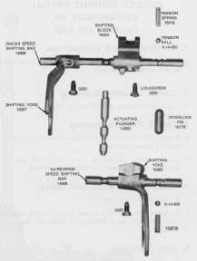
14 1. Remove Shift Bar Housing. 4. Remove actuating Plunger. 2. Remove two springs; remove ball under each spring. 5. Remove 1st-reverse speed shift bar and yoke. 3. Remove 2nd-3rd speed shift bar. 6. remove interlock pin from boss as last bar is withdrawn.


15 II. COMPANION FLANGE, AUXILIARY, AND CLUTCH HOUSING REMOVAL


16 3. Remove capscrews which attach auxiliary section to case; use puller screws to break gasket seal. 5. Remov bolts and nuts which attach clutch housing to case. 4. Pull auxiliary section straight to the rear and from transmission case. 6. Remove clutch housing from transmission. NOTE:Transmission can also be set vertically to remove the auxiliary section. Block undre clutch housing tp prevent damage to drive gear shaft, and lift the auxiliary upward and from transmission case.

17 III. FRONT SECTION A. To remove and Disassemble the Auxiliary Drive Gear Assembly


18 1. Remove large snap ring from ID of auxiliary drive gear. 4. remove the rear coupling snap ring from groove in mainshaft. 2. Insert puller screws and remove quill support plate from gear. 5. Remove lockwire and capscrews, insert puller screws and pull the auxiliary drive gear assembly from case bore. 3. Remove coupling gear from splines of mainshaft and bore of gear. 6. Remove auxiliary drive gear bearing nut, left-hand thread. Press retainer ring and bearing from drive gear.


19 B. To Remove and Disassemble the left Reverse Idler Gear Assembly


20 NOTE: To remove the left reverse idler gear, the reverse gear on the mainshaft must be moved forward to provide the necessary clearance. 4. remove oil plugand attach impact puller, theaded 1/2-13; pull shaft from gear. 1. Remove snap ring from ID of the reverse gear. 5. Remove reverse idler gear and washer from case. 2. Move reverse gear as far forward as possible on the shaft. 6. Remove bearing inner sleeve from gear; press bearing inner race from gear if necessary. 3. Remove retaining nut and washer from idler shaft threads. 7. Re-insert shaft through bearing and install thrust washer, retainer washer and nut on thread end; use as puller to remove bearing. Make sure nut is fully threaded on shaft.

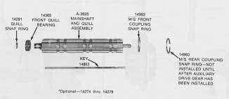
21 C. To Remove and Disassemble the Mainshaft Assembly


22 4. Pull key from mainshaft to free washers, spacers and gears. 1. Lift mainshaft assembly from case. 5. remove washers,spacers and gears from mainshaft. if necessary, remove snap rings from ID of gears. 2. Remove the front coupling snap ring from groove in mainshaft. 6. Place mainshaft in vise and remove snap ring from front quill. 3. Remove the reverse gear spacer. 7. Pull roller bearing from front quill.


23 D. To Remove the Countershaft Bearings 1. Remove snap ring from rear of right countershaft. 2. Remove the bearing retainer plate from front of right countershaft.


24 3. Move countershaft to the rear as far as possible, this will move rear bearing to the rear and partially unseat front bearing. 6. Use exposed snap ring to pull front bearing from countershaft 4. Block between rear bearing and case and move countershaft forward to unseat rear bearing. NOTE: It may be necessary to use soft bar and punch from inside case to move rear bearing to the rear far enough to clear case bore. 5. Front bearing snap ring will be exposed when countershaft is moved forward as shown in step Remove bearings from left countershaft in the same manner as bearings were removed from right countershaft.


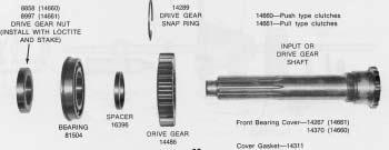
25 E. To Remove and Disassemble the drive Gear Assembly 1. Turn out capscrews and remove the front bearing cover. 2. Tap drive gear assembly forward and remove snapring from drive gear bearing.


26 3. Remove drive gear by moving to inside of case and working past countershafts. 6. press shaft through gear and bearing; Remove snapring from ID of drive gear if necessary. 4. Relieve drive gear bearing nut at points where peened into shaft. 5. Turn drive gear bearing nut from shaft, left-hand thread.


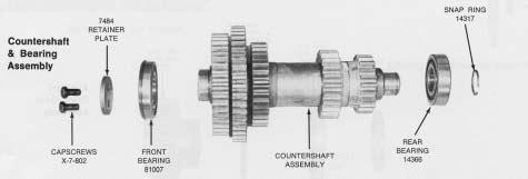
27 F. To Remove and Disassemble the Countershaft Assembly 1. Remove the right and left countershaft asemblies from case. 2. Remove snap ring from rear of countershaft.


28 3. Press the reverse and 1st speed gear from countershaft. 5. Remove spacer from countershaft. 4. Remove rear key from keyway in countershaft. 6. Press the 2nd speed gear, PTO gear, and drive gear from countershaft.


29 F. Countershaft Disassembly, Continued NOTE: Both countershafts are identical, except for the number of teeth on the PTO gears, thus they are Disassembled in the same manner. 7. Remove front key from keyway in countershaft. Remove front spacer from countershaft. G. To Remove and Disassemble the Right Reverse Idler Gear Assembly See page 20 for exploded view of left reverse idler gear assembly whitch is exactly the same as the right reverse idler gear assembly. 1. Remove the retaining nut and washer from the reverse idler gear shaft. 2. Use puller to remove shaft. Remove parts in the same manner as shown for the left reverse idler gear assembly, page 20.
30 IV.AUXILIARY SECTION


31 A. To Remove and Disassemble the Range shift Cylinder Assembly 1. Remove cover from range shaft air cylinder. 2. Turn nut from air cylinder shifting bar


32 3. Use air to remove piston from cylinder. Do not stand in back of piston. 6. Remove the shifting yoke and shift cylinder 7. Remove snap ring from bore in shift cylinder; this will free wasker and O-ring installed under snap ring 4. Remove Yoke lockscrews 5. Remove shifting bar from housing and yoke hub.


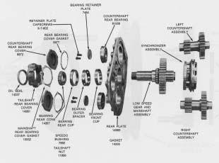
33 B. To Remove and Disassemble the Countershaft Assemblies 1. turn out capscrews and remove the countershaft rear bearing covers. 2. Cut lockwire and remove the bearing retainer plates.


34 3. Move countershafts forward to unseat from bearings. (NOTE: blocking under synchronizer assembly in addition to blocking under rear plate) Bearings are removed from rear plate by tapping evenly to the rear. 5. Press drive gears from countershafts, remove keys from shafts if necessary. 4. Remove snap rings from countershafts.


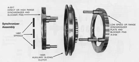
35 C. To Remove and Disassemble the Synchronizer Assembly 2. pull direct synchronizer from blocker pins of low speed synchronizer. Place cloth over ring during removal as springs direct ring will be released at arrow locations. 1. Remove synchronizer assembly from output shaft as a complete unit. 3.Remove sliding clutch gear from low speed synchronizer.


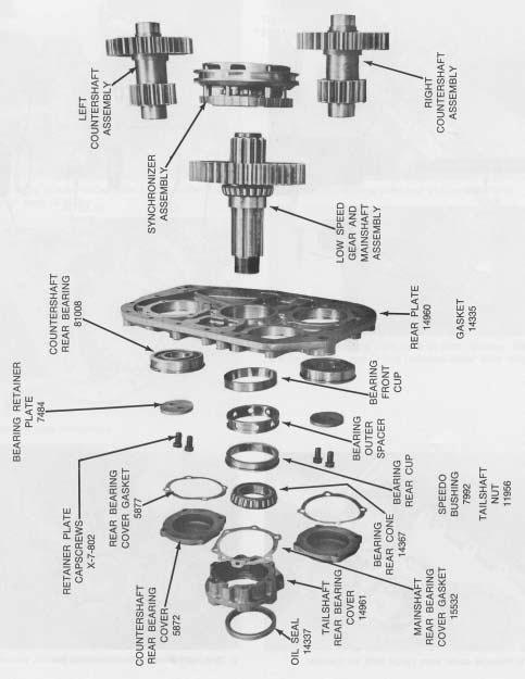
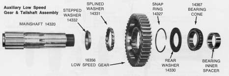
36 D. To Remove and Disassemble the Low Speed Gear and Tailshaft Assembly 3. Turn out capscrews and remove the rear bearing cover. If necessary, remove oil seal from cover. 1. Remove low speed gear and output shaft as a complete unit by moving forward and through bearing. (NOTE blocking under rear plate) 4. Remove the bearing rear cone. 2. Use gear as a base to press bearing from output shaft and free the gear and washers. If necessary, remove snap ring from gear. remove splined washer and stepped washer from shaft. 5. Remove the two bearing cups and outer spacer from bore.

37 GENERAL PRECAUTIONS FOR REASSEMBLY IMPORTANT: Read this section before starting the detailed reassembly procedures. Make sure that interiors of case and housings are clean. It is important that dirt be kept out of transmission during reassembly. Dirt is abrasive and can damage polished surfaces of bearings and washers. Use certain precautions, as listed below, during reassembly. 1.GASKETS - Use new gaskets throughout the transmission as it is being rebuilt. Make sure all gaskets are installed, as omission of gasket can result in oil leakage or misalignment of bearing covers (See Location of Gaskets heading). 2. CAPSCREWS - To prevent oil leakage, use shellac on all capscrews. See torque rating chart for recommended torque. 3. ASSEMBLY - Refer to the assembly illustration, pages 27-34, as a guide to reassembly. 6.BEARINGS - Use of flanged-end bearing drivers is recommended for the installation of bearings. These drivers apply equal force to both races of bearing, preventing damage to balls and races and maintaining correct bearing alignment with shaft and bore. If tubular or sleeve type driver is used, apply force only to inner race. 7. UNIVERSAL JOINT COMPANION FLANGE - Pull the companion flange tightly into place with the mainshaft nut, using ft. lbs. of torque. Make sure the speedometer gear is not used, a replacement spacer of the same width must be used. Failure to pull the yoke or flange tightly into place will permit the shaft to move axially with resultant damage to rear bearing. 4. INITIAL LUBRICATION - Coat all thrust washers and splines of shafts with Lubriplate during installation to provide initial lubrication, preventing scoring and galling. 5. AXIAL CLEARANCES - Maintain the following axial clearances: Mainshaft Forward Speed Gears Mainshaft Reverse Speed Gear Reverse Idler Gear Mainshaft


38 RASSEMBLY INSTRUCTIONS I. AUXILIARY SECTION A. To Reassemble and Install the Low Speed Gear and Tailshaft Assembly 3. Install snap ring in ID of low speed gear. 1. Install stepped washer on auxiliary mainshaft. 4. Install low speed gear on shaft. 2. Install splined washer on shaft and against stepped washer. 5. Install rear washer on shaft.


39 6. Install front cone of rear bearing on shaft; seat against washer. (heating of bearing cones will facilitate installtion. Use heat lamps and do not heat over 275 degrees F. 9. Tap all three units, front cup, outer spacer and rear cup evenly into bore until lip on rear seats on housing. 10. Place rear plate on shaft and frontbearing cone. 7. Install bearing inner spacer on shaft and against bearing cone. 11. Install bearing rear cone on shaft and into rear cup. 8. Place front cup of bearing partially in rear bore, taper to the inside. 12. Install the rear bearing cover. make sure oil seal has been installed in rear bearing cover.


40 B. To Reassemble and Install the Synchronizer Assembly 1. Install sliding clutch gear on pins of the lowspeed synchronizer. 3. Place direct synchronizer over pins of the low speed synchronizer with springs aganst the low speed blocker pins. 4. Compress springs to fully seat direct synchronizer on pins of low speed synchronizer. 2. Install the three springs in direct synchronizer. 5. Install synchronizer assembly on splines of output shaft.


41 C. To Reassemble, Time and Install the Countershaft Assembly NOTE: Both countershafts are assembled in the same manner. 1. Install keys in keyways of auxiliary countershaft and press drive gear on eachshaft; long hubagainst shaft sholder. 3. Mark timing teeth on countershaft low speed gears. Each tooth is aligned with keyway and stamped with an O. 2. Install snap ring on front of each countershaft. 4. Mark two tining teeth on each sideof low speed gear,directly opposite. mark any two adjacent teeth; then mark the two adjacent teeth which aredirectly opposite the first set of marked.


42 5. Place countershafts into position and time gears by meshing marked tooth on each countershaft between the two marked teeth on low speed gear. (rear plate is placed on blocking, approximately 8 high. Blocking must also be placed under synchronizer assembly). 7. Install bearing retainer plates on countershafts. Tighten and wire securely. 8. Install rear bearing covers, tighten capscrews securely. 6. Install rear bearings on countershafts and into rear bores.


43 D. To Reassemble and Install the range Shift Cylinder Assembly 1. Install O-ring in bore of range shift air cylinder. 4. Install shift cylinder and position shifting yoke in sliding clutch and cylinder housing 2. Install washer in shift cylinder agsinst O-ring. 5. Install the shifting bar; align notches with capscrew bores in yoke. 3. Install snap ring in shift cylinder to secure washer and O-ring. 6. Install yoke lockscrews, tighten and wire securely. Correctly position cylinder and install capscrews which attach cylinder to rear plate.


44 7. Install O-ring in ID of piston. 10. Install elastic stop nut on shifting bar. 8. Install O-ring on OD of piston. 11. Install shift cylinder cover. 9. Install piston on shifting bar and into cylinder bore.


45 II. FRONT SECTION A. To Reassemble and Install the Right Reverse Idler Gear Assembly Before starting the assembly, check to make sure all three magnetic discs are placed in the bottom of the case. These can be installed with 3M Brand adhesive, no. EC Install plug in reverse idler shaft. 4. Press needle bearing in bore of reverse idler gear. 2. Install cup on reverse ilder shaft. 5. Install reverse idler gear and thrust washer on shaft as shaft is inserted into bore. make sure needle bearing in gear seats on inner race evenly before completeing installation of shaft. 3. Install bearing inner raceon shaft and against cup. 6. Install elastic stop nut and retainer washer on shaft. (if desired the auxiliary countershaft front bearing can now be installed in the right reverse idler bore).

 on countershaft, long hub to the rear. 2.")


46 B. To Reassemble and install the Countershaft Assemblies Except for the number of teeth on the power take-off gears, the countershafts are identical and assembled in the same manner. 1. Install the countershaft front spacer. 3. Press the drive gear (3rd speed) on countershaft, long hub to the rear. 2. Install the front key in countershaft. 4. press the power tak-off gear on shaft, bullet nose of teeth to the rear. The left-side countershaft takes a 47 tooth PTO gear; the right -side countershaft takes a 45-tooth gear; After installing PTO gear on countershaft, mark assembly either left or right to correspond with installed PTO gear.


47 B. Countershaft Assemblies, Continued 5. Press 2nd speed gearon countershaft, long hub to the rear. 7. Press 1st speed gear on countershaft, long hubto the rear. 6. Install spacer on countershaft and install the rear key in keyway in countershaft; groove in spacer towards front of shaft. 8. press the reverse gear on countershaft, long hub to the front.

 into position in case.")


48 9. Install snap ring in groove at rear of countershaft. 12. Place the right countershaft assembly (45-Tooth PTO gear) into position in case. Do not install bearings. 10. mark timing tooth on each countershaft drive gear. Tooth is aligned with keyway and is stamped with an O. 13. Countershafts in position in case. 11. Place the left countershaft assembly (47 tooth PTO gear) into position in case. Do not install bearings.


49 C. To Reassemble and Install the Drive Gear Assembly 1. Install snap ring in ID of drive gear. 4. Drive gear bearing installed on shaft; a press fit. 2. Install drive gear on splines of shaft, snap ring of gear towards the front. 5. Apply grade AVV loctite sealant to threads of drive gear nut. Also apply sealant to threads of shaft. 3. Install spacer on shaft.


50 8. Mark drive gear teeth for timing, two adjacent teeth plus two adjacent teeth directly opposite. 6. Install the drive gear bearing nut, Left hand thread. Use ft.lb. of torque. Note: If torque wrench is not available, torque can be approximated by multiplying the pounds of pull times the length of wrench handle. Foe example: If there are 150 pounds of pull on a wrench with a two-foot handle, multiply 150 X 2 which equals 300 ft. lb. of torque. Ordinary pull scales can be used to measure pounds of pull. 9. Insert clutch shaft through bore from inside case, working drive gear past countershaft gears to seat bearing in front bore. 7. Peen nut into the two slots of shaft. To hasten the hardening of loctite, place the assembly under heat lamps 10to 15 minutes. 10. Install snap ring on drive gear bearing.


51 D. To Install the Countershaft Bearing and Tim the Gearing 1. Center front of left countershaft in case bore. 4. Install front bearing on left countershaft. make sure timing teeth are still in mesh. 2. Mesh the timing tooth of left coountershaft with timing teeth of drive gear. 5. Install the snap ring on rear of left countershaft. 3. Install rear bearing on left countershaft and into case bore. 6. Install the bearing retainer plate on front of left countershaft. Tighten and wire securely.


52 7. Mesh timing tooth of right countershaft with the two timing teeth on drive gear. 10. Install the snap ring on rear of right countershaft. 8. With front of shaft centered to bore, Install the rear bearing on right countershaft and in case bore. 11. Install the bearing retainer plate on right countershaft. Tighten and wire securely. 9. Install the front bearing on right countershaft and in case bore. 12. Install the drive gear bearing cover.
 limits are: Forward speed gears--.005 to.")


53 E. To Reassemble and install the mainshaft Assembly For referance purposes, the gear washerers are intenally splined and contain a square keyway. The gear spacers are externally splined to engage splines of gears. There is one washer and one spacer for each gear. Axial Clearnce (end play) limits are: Forward speed gears to.012 Reverse speed gear to.038 Washers are used to obtain the correct limits; six thicknesses are available as follows: PART NO. LIMITS COLOR CODE White Green Orange Purple Yellow Black 1. Install snap ring in ID of all mainshaft gears except the reverse speed gear. Always use the low limit washer (14274) in the Reverse, 1st speed gear positions and 2nd speed gear stop position (see assembly procedures). In most cases, when setting up the reverse gear clearance, the low limit washer will give the correct clearance. However, if desired, this clearance can be measured befor the mainshaft assembly is installed in the case. This is done by securing the reverse gear in opsition on mainshaft with the reverse gear snap ring and the front coupling snap ring; then, secure auxiliary drive gear assembly in position at rear of mainshaft with the rear coupling snap ring. 2. Install the reverse gear washer on shaft, flat side down, and insert key through keyway in washer. (use low limit washer). 3. Install the first-reverse sliding clutch on shaft.


54 4. Install the first speed gear washer, flat side up, engaging keyway with key. (use low limit washer). 6. Install the first speed gear on shaft and splines of spacer. The key is to be moved upwards to engage each part (except gears) as it is placed on mainshaft. 7. Install the first speed gear stop, mpve key up to lock in position. 5. Install the first speed gear spacer, flat side next to washer.


. 10. Install 2nd speed gear stop. 9.")

55 Mainshaft Assembly, Continued 8. Install the first speed gear stop washer flat side down, engaging keyway with key. (use washer to obtain correct end play. Use feeler gauge between hub of gear and stop to obtain reading). 10. Install 2nd speed gear stop. 9. Install the 2nd speed gear stop washer, flat side up engaging keyway with key. ( use Low limit washer.) 11. Install the 2nd speed gear, clutching teeth up.


56 12. Install the 2nd speed gear spacer into hubof gear, flat side up. 15. Install sliding clutch gear on mainshaft. 13. Install the 2nd speed gear washer in hub of gear, flat side down. 16. Install bearing on front of shaft. Photo shows special tool which seats bearing without changing quill location. 17. Install snap ring on quill to secure bearing. 14. turn the 2nd speed gear washer untill washer splines align with splines of shaft; lock with long key. (use washer to obtain correct end play. take reading with feeler gauge between gear hub and gear stop.)


57 18. Install reverse gear on mainshaft and aganst 1st speed gear, snap ring groove to the rear. 21. From inside case, insert rear of mainshaft through rear bearing bore; lower assembly into position. 19. Install the reverse gear, splined spacer on shaft and aganst washer, flat side towards washer. 22. Align 1st and 2nd speed gear teeth on mainshaft with those on countershaft; move assembly forward to seat quill bearing in drive gear pocket. 20. Install the front coupling snap ring on mainshaft to secure long key. 23. Mainshaft assembly correctly positioned


58 F. To Assemble and Install the Left Reverse Idler gear Assembly 1. Install plug in reverse Idler gear 5. seat shaft in bore; make sure needle bearing is aligned with bearing sleeve. 2. Install cup and bearing inner sleeve on shaft. 6. Install washer and retainer nut on threads of shaft. 3. press needle bearing into bore of reverse idler gear. 4. Place thrust washer and gear into position in case and insert shaft through gear and into boss. 7. Move the mainshaft reverse gear to the rear into mesh with reverse idler gears and install snap ring in ID of gear.


59 G. To Reassemble and Install the Auxiliary Drive Gear Assembly 1. Place retainer ring on auxiliary drive gear. 5. Install auxiliary drive gear assembly into case bore and over rear of mainshaft. Do not burr the face or edge of the tapered synchronizer surface. 2. Press bearing on drive gear 6. Install the six capscrews to attach retainer ring to case. wire capscrews in groups of three. 3. Apply loctite Grade AVV sealant to threads of auxiliary drive gear nut and drive gear. 4. Install bearing Nut, left-hand thread. 7. Pull mainshaft to the rear and install the mainshaft coupling snap ring in groove in mainshaft and groove in key.


60 8. Install the coupling gear in bore of auxiliary drive gear and splines of mainshaft. 10. Install the snap ring in auxiliary drive gear. 9. Install the rear quill support plate, flat side to the rear.


61 III. Clutch Housing, Auxiliary Section, and Compaion Flange Installation 1. Install Gasket and clutch housing on studs in front of housing; pilot on front bearing cover. 3. Recheck front section to make sure all parts have been installed: seat auxiliary countershaft front bearing in reverse idler bores if not previously installed, check to make sure both snap rings are installed on countershafts, check dowel pins, check for snap ring in ID of auxiliary drive gearr. 2. Install plain washers and nuts on six studs; Install shakeproof washers and four bolts. Use correct Torques: Nuts ft.lbs. Bolts ft.-lbs.


62 4. Install the auxiliary section on front section. Place a chain hoist on auxiliary assembly to properly balance and hold its weight. move the auxiliary section evenly onto rear of transmission. The two countershaft drive gears will mesh with the auxiliary drive gear, and front of countershaft will seat in the two bearing installed in the front section. move the assembly evenly, rotating drive gear if necessary, to properly mesh gears. Install attaching capscrews and tighten securely. 5. Install the speedometer drive gear on hub of flange or yoke. if speedometer gear is not used, install a replacment spacer of the same width. NOTE: Auxiliary section can also be installed by setting front section vertically on wood blocks and by lowering the auxiliary evenly on transmission. 6. Lock transmission by engaging two gears with the sliding clutch gears; install flange or yoke on splines of output shaft and secure with nut, using correct troque of ft.lb..


63 IV. Shifting Controls A. To Assemble and Install the Shifting Bar Housing Assembly 3. Install the interlock pin. 1. Install the first-reverse shifting bar yoke. Install lockscrew, tighten and wire securely 4. Install the second-third speed shifting bar Install lockscrews, tighten and wire securely. 2. Install the actuating plunger. 5. Install the two tension balls in bores at bar locations.l


64 6. Install tension springs. Install the orage spring in 1streverse rail position; green spring 2n-3rd position. 7. Install the shifting bar housing on transmission, fitting yoke forks into slots in sliding clutch gears. Shifting bar housing correctly assembled


65 B. To Reassemble and install the Gear Shift Lever Housing Assembly 1. install lockwasher and nut on gear shift lever pivot pin. 4. Seat the tension spring under lugs in housing. Insert shows spring correctly seated. 2. Install gear shift lever in housing, inserting pivot pin in slot in pivot ball of lever. 3. Place the tension spring washer in housing. 5. Install the gear shift lever housing on shifting bar housing, fitting lever into shifting slots in housing.


66 C. To Install the Range Shift Air System 1. Air valve and fittings. See page 12 for part numbers. 5. Install the air valve and gasket; use air to move piston either all the way forward or to the rear before installing air valve. 2. Install gasket and the air valve adapter plate. This takes two x caoscrews, and two x capscrews with x washers. Make sureadapter plate is perfectly aligned with bore in case. 6. Install the high range air line between port in range cylinder cover and rear port in air valve. 3. Install the actuating pin and spring in bore. 4. Install the alignment sleeve in air valve. 7. Install the Low range air line between port in range cylinder and front port to air valve.


67 C. Range Shift Air Syatem, Continued 8. Secure bracket to air regulator with hexagonal nut. Nipple is installed in air filter and bracket attached loosely with the two capscrews; nut and washer are placed on nipple and regulator threaded on nipple. 10. View of filter and regulator assembly properly installed and with hose clamped in position. 9. Install supply air line in output port of air regulator and install filter and regulator assembly on transmission. 11. Connect the supply air line from regulator to the tee in air valve.


68 12. Install the range control valve on gear shift lever with clamp. Position control valve so that top of button in up position is aproximately 6 below top of lever. Install ball grip. 14. install the white supply port of air valve. 13. Install the range control air lines valve. Black line is connected to the out port, and the white line is connected to the in or supply port. 15. Install the black air line at hex-end air port on air valve.l
69 AIR SYSTEM

70 RANGE SHIFT AIR SYSTEM Operation This system consiste of an air filter, regulator, air valve,control valve, shift cylinder, fittings and connecting lines. See page 70. Constant regulated air is supplied to the botton port of the air valve located on the side of the transmission. it is also supplied to the in port of the control valve on gear shift lever. With the control button down, air passes through the control valve and to the end port of the air valve. This aligns the actuating piston in air valve for low rangeporting, allowing air from the constant supply to flow through the low range port in front, side of air valve and to the low range port in the shift cylinder, located in the auxiliary section. Air on this port moves the range shift piston and bar to the rear to engage the low range gear. With the control button up, the control valve is closed and air is removed from the end port of air valve. This aligns the actuating piston in air valve for high range porting, allowing air from the constant supply to flow through the high range port inrear, side of air valve and to the high range port in the shift cylinder cover. Air on this port moves the range shift piston and bar forward to engage the high range gear. When the control button is moved from one positon to another, air from the previously charged line exhausts through the breather in air valve.

71 Air Valve Operation With the range control button up the control valve shuts off the air supply to the end cap. Thus, the constant air entering at the constant supply port forces the piston to the rear. The cinstant air also flows through a channel in the center of the piston and to an external port which is aligned with the high range port of the air valve. With the conrtrol button down the control valve opens and supplies air to the end cap. Since the piston area is larger on this end of the piston, it is forced in the oposite direction. The external air port in the piston is now aligned with the low range port of the air valve Exploded view of air valve. Part Numbers, which are subject to change, are FULLER part numbers. The alignment sleeve is not part of the assembly, but must be installed in the housing for proper pre-select operation. The four O-rings are indacated by circled numbers. if any of these are defective, there will be a constant air leak out of the exhaust on the air valve. In normal operation, exhaust will accure only for an instant as the range shfit is made. The following chart is to be used as a guide to determine defective O-rings. Defective O-rings RESULTS 1 Constant leak through exhaust in low range only. 2 or 3 Constant leak through exhaust in both ranges. 4 Constant leak through exhaust in high range; steady but low volume leak through exhaust in low range. To Disassemble Air Valve 1. Turn out the two capscrews and remove the side cap from valve body. 2. Remove the insert valve from piston and remove O-ring from the insert valve. 3. Remove the spring from the piston. 4. Turn end cap from valve body and withdraw piston from bore. 5. Remove the two O-rings from piston. 6. Remove the nylon plug from piston and remove O-ring fromplug.

72 Control Valve Operation Control Valve Operation If the o-rings or parts in the control valve are defective there will be a constant air leak out the exhaust located on bottom of control valve. A defective insert valve O-ring will result in a constant leak through exhaust in both ranges and valve will not make range shifts. A defective housing O-ring will result in a constant, low volume leak through exhaust in low range only. If the slide is assembled backwards, there will be a constant leak through exhaust in high range. When installing slide in control valve make sure that slot in slide faces the outlet port. To Disassemble the Control Valve 1. Place control vale with rear housing (outlet side) on bench and remove the four screws to separate front and rear housings. 2. Remove the slide and the two position balls and springs. 3. remove the flat metal seal from outlet side and remove the O-ring from body. 4. Remove the valve insert from front housing and remove the O-ring from the valve insert. 5. Remove te wave washer installed under valve insert. 6. Remove the two felt wipers from valve housing. Punch out roll pin and remove control button from slide. Qty. Table 1: Air Valve O-ring Sizes, III. C Part No. Location ID Width Valve Insert and Plug.208.o Piston Piston
73 Table 2: Control Valve O-ring Sizes, III. D Qty. Part No. Location ID Width Valve Insert Housing


74 Air Regulator Disassembly 1. Mount the air regulator in vise to bring slight pressure against body and end cap. 2. Back off the large lockring which attaches the end cap to body. 3. Slowly loosen vise against the spring pressure of regulator and remove the partsfrom end cap of regulator. 4. Remove the rubber diphragm and plate from body of regulator. 5. Remove snap ring, washer and small spring from input piston. 6. Push the piston out through the input port of regulator. 7. Remove seal from piston bore.. Air Filter The air filter contains a replaceable filter which can be removed by turning out the bolt at the top of the filter and disengaging the body from cover. The filter should be serviced every 10,000 miles, or more often under high humidity conditions. Air Valve Pre-Selection An actuating pin protruding from the shifting bar housing prevents the actuating piston in the air valve from moving while the gear shift lever is in a gear position and releases the pistion when the lever is moved to or through neutral. See detailed installation of air valve for installation precaution concerning the actuating pin.


75 Range Shift- Air System Operation


76 Range Shift Air System- Troubleshooting


77 Range Shift Air System- Troubleshooting To Check Control valve Correct Control Valve Operation


78 For Correct Operation (Normal Line Pressure, Engine Off)

79 Range Shift Air System- Troubleshooting
80 Inspection Before reassembling the transmission, the individual parts should be carefully checked to eliminate those damaged from previous service. This inspection procedure should be carefully followed to insure the maximum of wear life from the rebuilt unit. The cost of a new part is generally a small fraction of the total cost of downtime and labor, should the use of a questionable part make additional repairs necessary before the next regularly scheduled overhaul. Recommended inspection procedures are set forth in the following checklist: A. Bearings 1. Wash all bearings in clean solvent. Check balls, rollers and races for pits and spalled areas. Replace bearings which are pitted or spalled. 2. Lubricate bearings which are not spalled or pitted and check for axial and radial clearances. Replace bearings with excessive clearances. 3. Check fits of bearings in case bores. If outer races turn freely in the bores, the case should be replaced. B. Gears 1. Check operating gear teeth for pitting on the tooth faces. Gears with pitted teeth should be replaced. 2. Check all engaging gear teeth. Gears with teeth worn, tapered or reduced in length from clashing in shifting should be replaced. 3. Check axial clearances of gears. Where excessive clearance is found, check gear snap ring, washer, spacer and gear hub for excessive wear. Maintain axial clearance of mainshaft forward speed gears,.005 minimum on reverse gear. C. Splines 1. Check splines on all shafts for wear. If sliding clutch gears, companion flange or clutch hubs have worn into the sides of the splines, the shafts in this condition should be replaced. D. Thrust Washers 1. Check surfaces of all thrust washers. Washers scored or reduced in thickness should be replaced. E. Reverse Gear and Shaft 1. Check bearing sleeve for wear from action of roller bearings. F. Gray Iron Parts 1. Check all gray iron parts for cracks and breaks. Replace or repair parts found to be damaged. Heavy casting may be welded or brazed providing the cracks do not extend into bearing bores or bolting surfaces. G. Clutch Release Parts 1. Check clutch release parts. Replace yokes worn at cam surfaces and bearing carrier worn at contact pads. 2. Check pedal shafts. Replace those worn at bearing surfaces. H. Shifting Bar Housing Assembly 1. Check yokes and blocks for wear at pads and lever slot. Replace worn parts. 2. Check yokes for alignment. 3. Check yokes for excessive wear; replace worn yokes. 4. Check lockscrews in yokes and blocks. Tighten and rewire those found loose. 5. If housing has been dismantled, check neutral notches of shifting bars for wear from interlock balls. Bars indented at points adjacent to the neutral notch should be replaced.
81 I. Gear Shift Lever Housing Assembly 1. Check spring tension on shift lever. Replace tension spring and washer if lever moves too freely. 2. If housing is dismantled, check pivot or spade pin and corresponding slot in lever for wear. Replace both parts if worn. 5. J. Bearing Covers 1. Check covers for wear from thrust of adjacent bearing. Replace covers worn and grooved from thrust of bearing outer race. 2. Check bores of covers for wear. Replace those worn oversize. K. Oil Return Threads and Seals 1. Check oil return in front bearing cover. If sealing action of threads has been destroyed by contact with input shaft, replace cover. 2. Check oil seal in mainshaft rear bearing cover. If sealing action of lip has been destroyed, replace seal. L. Sliding Clutches 1. Check all yokes and yoke slots in sliding clutches for extreme wear or discoloration from heat. 2. Check engaging teeth of sliding clutches for partial engagement pattern. M. Front Bearing Cover 1. Check inside hub of from bearing cover for wear caused by backing off of drive gear bearing nut. Reassemble Precautions Make sure that interiors of case and housings are clean. It is important that dirt be kept out of transmission during reassembly. Dirt is abrasive and can damage polished surfaces of bearings and washers. Use certain precautions, as listed below, during reassembly. 1. GASKETS - Use new gaskets throughtout the transmission as it is being rebuilt. Make sure all gaskets are installed, as omission of gasket can result in oil leakage or misalignment of bearing covers (See Location of Gaskets heading). 2. CAPSCREWS - To prevent oil leakage, use thread sealant on all capscrews. 3. ASSEMBLY - Refer to the disassembly illustration as a guide to reassembly. 4. INITIAL LUBRICATION - Coat all thrust washers and splines of shafts with Lubriplate during installation to provide initial lubrication, preventing scoring and galling.
82 TORQUE RATINGS CAPSCREWS AND NUTS Recommended torque ratings, location and size of capscrews and nuts are listed below. caoscrew lenghts are given for referance purposes as a guide for installation at proper locations. Correct torque application is extremely important to assure long transmission life and dependable performance. Over-tightening or under-tightening can result in poor installation and, in many instances, eventually cause damage to transmission gears, shafts,or bearings. Do not torque capscrews dry. Table 1: CAPSCREWS Qty. Part No. Size Location Torque Rating Foot-Pounds 2 x-8s-429 1/4-20x 3/4 Air filter to bracket x x /4-20x 5/8 Air valve adapter plate x-8-410* 1/4-20x 78 Air valve adapter plate, rear x x-8-411* 1/4-20x1 3/4 Air Valve x x-8s-601 3/8-16x 3/4 PTO cover, small 18-23** 2 x-8l-601 3/8-16x 3/4 Air filter bracket to case x /8-16x 1 Auxiliary drive gear bearing retainer x-8l-604 3/8-16x1 1/4 Frontbearing cover x-8l-604 3/8-16x1 1/4 Shift bar housing x-8l-604 3/8-16x1 1/4 gear shift lever huosing x-8l-604 3/8-16x1 1/4 Auxiliary countershaft rear bearing covers x-8l-604 3/8-16x1 1/4 Auxiliary range shift cylinder to rear plate x-8l-604 3/8-16x1 1/4 Auxiliary range shift cylinder cover x-8l-609 3/8-16x1 3/4 Rear plate to case x-8-614* 3/8-16x 2 Auxiliary housing x x-8-616* 3/8-16x 2 3/4 Rear bearing cover (5) x (1) x-3-605, Bottom right x-8-700* 7/16-14x 1 1/4 PTO cover, large x x /2-13x 11/2 Clutch housing x x /2-13x 3 1/2 Clutch housing x x /2-20x 1 Countershaft front bearing retainer x /2-20 x 1 Auxiliary countershaft rear bearing retainer x /2-20 x 2 Range shift yoke *THESE CAPSCREWS REQUIRE LOCKWASHERS. Those not starred have lockwashers as part of the capscrew assembly, or do not require lockwashers. ** ft.lb. when used with oil filter.
83 NUTS Table 1: Qty. Part No. Size Location Torque Rating Foot-Pounds 1 x /8-24 Gear shift lever pivot pin x /8-18 Clutch housing. (Aluminum to case x /8-18 Reverse Idler Shaft x /8-18 case-vertical Mtg. Studs x /8-18 Case to Clutch Housing (cast Iron) x /8-18 Range cylinder shift bar Output Shaft GASKETS Table 2: Part No. Location Part No. Location Aux. rear bearing cover Clutch housing 5877 Aux. countershaft rear bearing cover (2) Auxiliary housing to case Range shift cylinder Shift bar housing Range shift cylinder cover 1642 Gear shift lever housing 1684 PTO cover, Small Air valve adapter plate PTO cover, Large Air Valve Front bearing cover Reverse switch hole plug PLUGS Table 3: Part No. Size Location Part No. Size Location x /8-27 Air valve x /4 P Filter hole x /2-14 heat gauge bore /2-13 Reverse idler shafts x /4-18 Shift bar housing /16-18 reverse switch hole x /4-14 Drain hole

84 Preventive Maintenance Check Chart
85 Preventive Maintenance Check Chart Checks without Partial Disassembly of Chassis or cab 1. Air System and Connections a. Chech for leaks, worn air lines, loose connections for looseness. 2. Clutch housing Mounting a. Chack all capscrews in bolt circle of clutch housing for looseness. 3. Clutch Release Bearing a. Remove hand hole cover and check radial and axial clearances in release bearing. b. check relative position of thrust surface of release bearing with thrust sleeve on push type clutches. 4. Clutch Pedal Shaft and Bores a. Pry upwards to check for wear. b. If excessive movement is found, remove clutch release mechanism and check bushings in bores and wear on shafts. Checks With Driveline Dropped 9. Universal joint Companion Flange Nut a. Check for tightness. Tighten to recommeneed torque. Checks With Universal Joint comoanion Flange Removed 10. Output Shaft a. Check splines for wear from movement and chuching action of the universal joint companion flange. b. Pry upward against output shaft to check radial clearance in mainshaft rear bearing. 11. Mainshaft Rear Bearing Cover a. Check oil seal for wear. 5. Gear Lubricant a. Change at specified service intervals. b. Use only gear oils as recommended. See lubricantion section. 6. Filler and Drain Plugs a. Remove filler plug and check level of lubricant at specified intervials. Tighten filler and drain plugs securely. 7. Gear Shift Lever a. Check for looseness and free play in housing. If lever is loose in housing, proceed with check no Gear Shift Lever Housing Assembly a. Remove air lines at air valve and remove the gear shift lever housing assembly from transmission. b. Check tension spring and washer for set and rear. c. Check the gear shift lever pivot pin and pivot pin slot for wear. d. Check bottom end of gear shift lever for wear and check slot of yokes and blocks in shfit bar housing for wear at contact points with shift lever.


86 Parts Referance


87 Parts Reference

88 Parts Reference


89 Parts Reference

90 Parts Reference
Service Manual. Fuller Medium Heavy Transmissions TRSM0201 October 2007
 Service Manual Fuller Medium Heavy Transmissions TRSM0201 October 2007 Model Designations...2 Description...3 Specifications...4 Lubrication...5 Conversion to Overdrive...6 Clutch Shaft Replacement...6
Service Manual. Fuller Mechanical Transmissions TRSM0992 October 2007
 Service Manual Fuller Mechanical Transmissions TRSM0992 October 2007 Introduction Warnings and Precautions Before starting a vehicle always be seated in the driver s seat, place the transmission in neutral,
Service Manual. Fuller Heavy Duty Transmissions TRSM0515 October 2007
 Service Manual Fuller Heavy Duty Transmissions TRSM0515 October 2007 TABLE OF CONTENTS Timing Description Operations Lubrication Preventive Maintenance Torque Recommendations Air System Precautions Disassembly
Transmission Overhaul Procedures-Bench Service
 How to Assemble the Lower Reverse Idler Gear Assembly Special Instructions In 1996 Eaton changed the reverse idler system design. In the nut design, the reverse idler bearing was lubricated through a hole
Transmission Overhaul Procedures-Bench Service
 How to Install the Auxiliary Countershaft Assembly Special Instructions To make auxiliary section assembly easier, you can make an auxiliary section fixture out of a 2" x 12" piece of wood. 3' 1' 3" 4.56"
Service Manual. Fuller Heavy Duty Transmissions TRSM0250 October 2007
 Service Manual Fuller Heavy Duty Transmissions TRSM0250 October 2007 TABLE OF CONTENTS FOREWORD........................................ MODEL DESIGNATIONS AND SPECIFICATIONS.......... LUBRICATION......................................
Fuller Heavy Duty Transmissions TRSM0503 October 2007
 Service Manual Fuller Heavy Duty Transmissions TRSM0503 October 2007 RTX-12510 RTX-12515 RTXF-12510 RTXF-12515 Table of Contents Model Designations..............................3 Description....................................4
Service Manual. Fuller Heavy Duty Transmissions. Fuller Heavy Duty Transmissions. October 2007 TRSM0300. More time on the road
 Fuller Heavy Duty Transmissions More time on the road Service Manual Fuller Heavy Duty Transmissions TRSM0300 October 2007 RTO-11607L RTO-11607L RTO-11607LL RTO-11607LL RTOF-11607L RTOF-11607LL TABLE
Fuller Mid-Range Transmissions TRDR0100
 Driver Instructions Video Instruction Available Instructional videos are available for download at no charge at roadranger.com Videos are also available for purchase. To order, call 1-888-386-4636. Ask
Fuller Mid-Range Transmissions TRSM0160 October 2007
 Service Manual Fuller Mid-Range Transmissions TRSM0160 October 2007 FS-5106A FS-6206A Before starting a vehicle always be seated in the drivers seat, place the transmission in neutral, set the parking
For the most current information, visit the Roadranger web site at
 Eaton Fuller Heavy Duty Transmissions 8 - Speed Direct Drivers Instructions TRDR-0310 March 2004 For the most current information, visit the Roadranger web site at www.roadranger.com Warnings Warnings
MANUAL TRANS OVERHAUL - BORG-WARNER - T56 6-SPEED MANUAL TRANSMISSIONS Borg-Warner T56 (MM6) 6-Speed
 6-Speed") IDENTIFICATION MANUAL TRANS OVERHAUL - BORG-WARNER - T56 6-SPEED 1998 MANUAL TRANSMISSIONS Borg-Warner T56 (MM6) 6-Speed Transmission has 2 identification labels, located on lower left side of case. One
IDENTIFICATION MANUAL TRANS OVERHAUL - BORG-WARNER - T56 6-SPEED 1998 MANUAL TRANSMISSIONS Borg-Warner T56 (MM6) 6-Speed Transmission has 2 identification labels, located on lower left side of case. One
SECTION 5B MANUAL TRANSMISSION TABLE OF CONTENTS
 SECTION 5B MANUAL TRANSMISSION TABLE OF CONTENTS General Description and Operation... 5B-2 Shift Lever... 5B-2 Transmission Assembly... 5B-2 Specifications... 5B-3 Diagnostic Information and Procedures...
Telephone (925) Fax (925) Lawrence Drive,Livermore, California
 Fax (925) Lawrence Drive,Livermore, California") Telephone (925) 454-9500 Fax (925) 454-9501 151 Lawrence Drive,Livermore, California 94551 www.fabcoautomotive.com Fabco Automotive Corporation Transfer Case Service Manual Model TC-33 625 320 Copyright
Telephone (925) 454-9500 Fax (925) 454-9501 151 Lawrence Drive,Livermore, California 94551 www.fabcoautomotive.com Fabco Automotive Corporation Transfer Case Service Manual Model TC-33 625 320 Copyright
Service Manual. Fuller Heavy Duty Transmissions
 Fuller Heavy Duty Transmissions More time on the road Service Manual Fuller Heavy Duty Transmissions TRSM0430 July 2010 RT-8608L RTF-8608L RTO-11608LL RTO-14608LL RTOF-11608LL RTOF-14608LL RTX-11608LL
Fuller Heavy Duty Transmissions TRSM0660 October 2007
 Service Manual Fuller Heavy Duty Transmissions TRSM0660 October 2007 RTLO-14613B RTLOF-14613B TABLE OF CONTENTS FOREWORD............. MODEL DESIGNATIONS AND LUBRICATION............ OPERATION.............
Telephone (925) Fax (925) Lawrence Drive, Livermore, CA
 Fax (925) Lawrence Drive, Livermore, CA") Telephone (925) 454-9500 Fax (925) 454-9501 151 Lawrence Drive, Livermore, CA 94551 www.fabcoautomotive.com SERVICE MANUAL TC-140 TRANSFER CASE TWO SPEED, TC-141 SINGLE SPEED Table of Contents I. TC-140
Telephone (925) 454-9500 Fax (925) 454-9501 151 Lawrence Drive, Livermore, CA 94551 www.fabcoautomotive.com SERVICE MANUAL TC-140 TRANSFER CASE TWO SPEED, TC-141 SINGLE SPEED Table of Contents I. TC-140
Service Manual. Fuller Heavy Duty Transmissions TRSM0880 October 2007
 Service Manual Fuller Heavy Duty Transmissions TRSM0880 October 2007 For parts or service call us Pro Gear & Transmission, Inc. 1 (877) 776-4600 (407) 872-1901 parts@eprogear.com 906 W. Gore St. Orlando,
Eaton Fuller Heavy Duty Transmissions
 Eaton Fuller Heavy Duty Transmissions 13 Speed Models Driver Instructions TRDR-0630 May 2004 For the most current information, visit the Roadranger web site at www.roadranger.com General Information Warnings
Fuller Automated Transmissions TRSM0020 October 2007
 Service Manual Fuller Automated Transmissions TRSM000 October 007 RT-09A-AT RT-09A-ATR RT-09A-ATS RT-09A-AT RT-409A-ATS RTO-09A-AT RTO-09A-ATS RTO-09B-AT RTO-09B-ATE RTO-09B-ATR RTO-09B-ATS RTO-09A-AT
1984 Dodge W250 PICKUP
 1984 Dodge W250 PICKUP Submodel: Engine Type: V8 Liters: 5.2 Fuel Delivery: CARB Fuel: GAS Dana 44 MODELS THROUGH 1984 2. Raise and safely support the vehicle, then remove the wheel hub and bearings as
Eaton Fuller Advantage Heavy-Duty Manual Transmissions TRSM0970 EN-US
 Service Manual Eaton Fuller Advantage Heavy-Duty Manual Transmissions TRSM0970 EN-US January 2016 FA(F)-9810B FA(F)-11810B FA(F)-12810B FA(F)-13810B FA(F)-14810B FA(F)-15810B FAO(F)-11810C FAO(F)-12810C
MANUAL TRANSMISSION SECTION MT CONTENTS TRANSMISSION/TRANSAXLE MT-1 SERVICE INFORMATION POSITION SWITCH...13 Checking...13
 TRANSMISSION/TRANSAXLE SECTION MT A B MANUAL TRANSMISSION MT D CONTENTS E SERVICE INFORMATION... 2 PRECAUTIONS... 2 Service Notice or Precaution...2 PREPARATION... 3 Special Service Tool...3 Commercial
3.2 DRIVE TORQUE HUB. Roll, Leak and Brake Testing SECTION 3 - CHASSIS & TURNTABLE. 3-2 JLG Lift
 3.2 DRIVE TORQUE HUB Roll, Leak and Brake Testing 10 LUG PATTERN Torque-Hub units should always be roll and leak tested before disassembly and after assembly to make sure that the unit's gears, bearings
MANUAL TRANSAXLE Return to Main Table of Contents
 MANUAL TRANSAXLE Return to Main Table of Contents GENERAL... 2 MANUAL TRANSAXLE CONTROL... 12 SHIFT LEVER ASSEMBLY... 14 MANUAL TRANSAXLE... 15 MANUAL TRANSAXLE ASSEMBLY... 17 FIFTH SPEED SYNCHRONIZER
Parts List PL_TR-TO-10_0714
 Torque Transfer Solutions TR-TO-10 Series 10-Speed Twin Counter Shaft Manual Transmission Parts List PL_TR-TO-10_0714 14700 Helm Ct. Plymouth, MI 48170 U.S.A. (800) 401-9866 www.tremec.com Copyright 2014
SPECIAL TOOLS Dodge Pickup 5.9L Eng R3500. Fig 1: Identifying Remover C-3985-B (Special Tool) 9/6/13 Printer Friendly View
 9/6/13 Printer Friendly View") Procedures 2003 Dodge Pickup 5.9L Eng R3500 manual transmission SPECIAL TOOLS Fig 1: Identifying Remover C-3985-B (Special Tool) www2.prodemand.com/print/index?content=tabs&module=true&tab=true&terms=true&ymms=false&classname=
Procedures 2003 Dodge Pickup 5.9L Eng R3500 manual transmission SPECIAL TOOLS Fig 1: Identifying Remover C-3985-B (Special Tool) www2.prodemand.com/print/index?content=tabs&module=true&tab=true&terms=true&ymms=false&classname=
Service Manual. Fuller Mid Range Transmissions TRSM0195 October 2007
 Service Manual Fuller Mid Range Transmissions TRSM0195 October 2007 Caution - Before towing the vehicle, be sure to lift the rear wheels off the ground or disconnect the driveline to avoid damage to the
TC20 Chain Driven Power Take-Off Overhaul Instructions
 TC20 Chain Driven Power Take-Off Overhaul Instructions Table of Contents Section Page Introduction 4 Ordering Repair Parts 4 General Information 5 Special Tools 6 Disassembly See Page 2 Reassembly See
SUZUKI SQ 416/420/625 M.Y TRANSMISSION SERVICE MANUAL - MANUAL - AUTOMATIC - TRANSFER - DIFFERENTIALS
 SUZUKI SQ 416/420/625 M.Y 1998-2005 TRANSMISSION SERVICE MANUAL - MANUAL - AUTOMATIC - TRANSFER - DIFFERENTIALS WARNING/CAUTION/NOTE IMPORTANT Please read this manual and follow its instructions carefully.
2001 Dodge RAM 3500 PICKUP
 1 of 76 9/14/2012 7:02 PM 2001 Dodge RAM 3500 PICKUP Submodel: Engine Type: L6 Liters: 5.9 Fuel Delivery: FI Fuel: DIESEL Subarticles MANUAL- NV3500 - DISASSEMBLY MANUAL- NV3500 - DISASSEMBLY MANUAL -
MANUAL TRANSMISSION MUA 5C (4X2, 4X4) AND TREMEC T5R(4X2)
 AND TREMEC T5R(4X2)") MANUAL TRANSMISSION 7B 1 RODEO TRANSMISSION MANUAL TRANSMISSION MUA 5C (4X2, 4X4) AND TREMEC T5R(4X2) CONTENTS Service Precaution...................... 7B 2 General Description..................... 7B
MANUAL TRANSMISSION 7B 1 RODEO TRANSMISSION MANUAL TRANSMISSION MUA 5C (4X2, 4X4) AND TREMEC T5R(4X2) CONTENTS Service Precaution...................... 7B 2 General Description..................... 7B
 Page 1 of 15 Transmission, Model S5-42 ZF Model S5-42 ZF Disassembly NOTE: For 4x4 and F-Super Duty vehicles, skip to Step 5. 1. Attach the transmission to the Bench Mounted Holding Fixture T57L-500-B
Fuller Heavy-Duty Transmissions TRSM1500 EN-US May 2017
 Service Manual Fuller Heavy-Duty Transmissions TRSM1500 EN-US May 2017 RT-8908LL RTO-11707LL RTO-11708LL RTOF-11707LL RTOF-11708LL RTOF-14708LL RTX-11708LL RTX-14708LL RTXF-11708LL RTXF-14708LL RTO-11707DLL
Maintenance Instructions
 General Note These instructions contain information common to more than one model of Bevel Gear Drive. To simplify reading, similar models have been grouped as follows: GROUP 1 Models 11, 0, 1,, (illustrated),,
UltraShift PLUS Automated Transmissions TRSM0940 EN-US
 Service Manual UltraShift PLUS Automated Transmissions TRSM0940 EN-US April 2016 UltraShift PLUS Linehaul Active Shifting (LAS) UltraShift PLUS Vocational Active Shifting (VAS) UltraShift PLUS Multipurpose
Maintenance Information
 80234313 Edition 1 June 2006 Air Grinder, Die Grinder, Sander and Belt Sander Series G1 (Angle) Maintenance Information Save These Instructions WARNING Always wear eye protection when operating or performing
FSO Transmission. Service Manual. Eaton Fuller Light Duty Transmissions. 3rd Ed. 03/10
 FSO-4505 Service Manual Transmission Eaton Fuller Light Duty Transmissions 3rd Ed. 03/10 General Information 1 Input Shaft Bearing Cover 2 Gear Shift Lever Housing 3 Main Section 4 Shifting System 5 Rear
TRANSMISSION AND TRANSFER CASE
 DR TRANSMISSION AND TRANSFER CASE 21-1 TRANSMISSION AND TRANSFER CASE TABLE OF CONTENTS page MANUAL TRANSMISSION- G56- SERVICE INFORMATION...1 MANUAL TRANSMISSION- GETRAG 238- SERVICEINFORMATION...69 MANUAL
1994 Mitsubishi Eclipse GS
 APPLICATIONS CHRYSLER MOTORS MANUAL TRANS OVERHAUL - MITSUBISHI W5M & W6M SERIES MANUAL TRANSMISSIONS Mitsubishi W5M31, TRANSMISSION APPLICATIONS (CHRYSLER MOTORS) Vehicle Application Transmission Model
Service Manual. Fuller Mid Range Transmissions TRSM0197 October 2007
 Service Manual Fuller Mid Range Transmissions TRSM0197 October 2007 Caution - Before towing the vehicle, be sure to lift the rear wheels off the ground or disconnect the driveline to avoid damage to the
Maintenance Information
 80234313 Edition 2 May 2014 Air Grinder, Die Grinder, Sander and Belt Sander Series G1 (Angle) Maintenance Information Save These Instructions Product Safety Information WARNING Failure to observe the
DISASSEMBLY. Transmission. 2. Remove the 4 clutch housing bolts. Separate the clutch housing from the transmission.
 308-03A-1 DISASSEMBLY Transmission 308-03A-1 Special Tool(s) Puller, Bearing 205-D064 (D84L-1123-A) or equivalent Remover/Installer, Front Wheel Hub 204-069 (T81P-1104-C) 2. Remove the 4 clutch housing
TSM54/52 MANUAL TRANSMISSION
 3B-1 SECTION 00 3B TSM54/52 MANUAL TRANSMISSION Table of Contents GENERAL INFORMATION... 3B-3 Overview... 3B-3 Specifications... 3B-4 System components... 3B-5 Shifting mechanism... 3B-17 Diagnostic information
TRANSMISSION AND TRANSFER CASE
 XJ TRANSMISSION AND TRANSFER CASE 21-1 TRANSMISSION AND TRANSFER CASE TABLE OF CONTENTS page AX5 MANUAL TRANSMISSION... 1 NV3550 MANUAL TRANSMISSION... 42 AUTOMATIC TRANSMISSION 30RH... 88 page AW 4 AUTOMATIC
TRANSFER CASE Mitsubishi Montero APPLICATION DESCRIPTION TESTING 4WD INDICATOR CONTROL UNIT (MONTERO) DETECTION SWITCH
 DETECTION SWITCH") TRANSFER CASE 1993 Mitsubishi Montero 1991-94 TRANSFER CASES Mitsubishi Dodge; Ram-50 Mitsubishi; Pickup, Montero APPLICATION TRANSFER CASE APPLICATIONS TABLE Application (1) Transmission Model Dodge 1991-93
TRANSFER CASE 1993 Mitsubishi Montero 1991-94 TRANSFER CASES Mitsubishi Dodge; Ram-50 Mitsubishi; Pickup, Montero APPLICATION TRANSFER CASE APPLICATIONS TABLE Application (1) Transmission Model Dodge 1991-93
MANUAL TRANSMISSION SECTION MT CONTENTS C TRANSMISSION/TRANSAXLE MT-1
 MANUAL TRANSMISSION C TRANSMISSION/TRANSAXLE SECTION MT A B MANUAL TRANSMISSION MT D CONTENTS E PRECAUTIONS... 2 Caution... 2 Precautions for Battery Service... 2 PREPARATION... 3 Special Service Tools...
REMOVAL & INSTALLATION
 REMOVAL & INSTALLATION AXLE SHAFTS & BEARINGS Removal CAUTION: Failure to turn off air suspension power before raising vehicle may result in unexpected inflation or deflation of air springs. DO NOT reconnect
Telephone (925) Fax (925) Lawrence Drive, Livermore, CA
 Fax (925) Lawrence Drive, Livermore, CA") Telephone (925) 454-9500 Fax (925) 454-9501 151 Lawrence Drive, Livermore, CA 94551 www.fabcoautomotive.com Fabco Automotive Corp. TC-35 TRANSFER CASE Service Manual TABLE OF CONTENTS Title Page with Index
Telephone (925) 454-9500 Fax (925) 454-9501 151 Lawrence Drive, Livermore, CA 94551 www.fabcoautomotive.com Fabco Automotive Corp. TC-35 TRANSFER CASE Service Manual TABLE OF CONTENTS Title Page with Index
Maintenance Information
 45528270 Edition 1 June 2007 Barring Motor T480 Series Maintenance Information Save These Instructions WARNING Always wear eye protection when operating or performing maintenance on this Barring Motor.
Valtek Auxiliary Handwheels and Limit Stops
 Valtek Auxiliary s and Limit Stops Table of Contents Page 1 General information 2 Installation 2 Side-mounted handwheels, size 25 and 50 (linear actuators) 3 Side-mounted handwheels, size 100 and 200 (linear
Service Manual. Fuller Mid Range Transmissions TRSM0194 October 2007
 Service Manual Fuller Mid Range Transmissions TRSM0194 October 2007 Caution - Before towing the vehicle, be sure to lift the rear wheels off the ground or disconnect the driveline to avoid damage to the
2008 F-Super Duty Workshop Manual
 13. Remove the mainshaft rear bearing cover. Inspect the mainshaft rear bearing cup for wear and damage. Install a new one as needed. Remove and discard the mainshaft rear bearing cover oil seal. 14. Remove
1989 Jeep Cherokee. STEERING COLUMN' '1989 STEERING Jeep Steering Columns STEERING COLUMN STEERING Jeep Steering Columns
 STEERING COLUMN 1989 STEERING Jeep Steering Columns DESCRIPTION All models use collapsible steering columns. All columns have integral ignition switch and locking device. Optional tilt wheel is available
Maintenance Information
 04581245 Edition 2 May 2014 Air Grinder, Die Grinder and Sander Series G2 (Angle) Maintenance Information Save These Instructions Product Safety Information WARNING Failure to observe the following warnings,
CHASSIS CONTENTS EXTERIOR PARTS 6-1 FRONT WHEEL 6-2 FRONT BRAKE 6-6 HANDLEBARS 6-12 REAR WHEEL 6-30 REAR BRAKE 6-34 REAR SHOCK ABSORBER 6-36
 CHASSIS CONTENTS EXTERIOR PARTS 6-1 FRONT WHEEL 6-2 FRONT BRAKE 6-6 HANDLEBARS 6-12 FRONT FORK ( ) 6-14 FRONT FORK ( ) 6-20 STEERING 6-27 REAR WHEEL 6-30 REAR BRAKE 6-34 REAR SHOCK ABSORBER 6-36 6 SWING
This file is available for free download at
 This file is available for free download at http://www.iluvmyrx7.com This file is fully text-searchable select Edit and Find and type in what you re looking for. This file is intended more for online viewing
CHAPTER 7 TRANSMISSION (MFO6S)
") 1 page INDEX1 Model SG1J (MF06S) TRANSMISSION 7-1 7-142E-07 CHAPTER 7 TRANSMISSION (MFO6S) Model SG1J 1 Models FE, FF and SG2J 1 Model FD 7 TROUBLESHOOTING...7-2 SPECIAL TOOLS...7-5 REMOVAL...7-7 GEAR
1 page INDEX1 Model SG1J (MF06S) TRANSMISSION 7-1 7-142E-07 CHAPTER 7 TRANSMISSION (MFO6S) Model SG1J 1 Models FE, FF and SG2J 1 Model FD 7 TROUBLESHOOTING...7-2 SPECIAL TOOLS...7-5 REMOVAL...7-7 GEAR
TRANSMISSION 6.7 GENERAL HOME. See Figure The transmission is a five-speed constantmesh type housed in an extension of the crankcase.
 TRANSMISSION 6.7 GENERAL See Figure 6-45. The transmission is a five-speed constantmesh type housed in an extension of the crankcase. Mainshaft Neutral Mainshaft st Gear b06x6x Countershaft 4 Out 5 Countershaft
TRANSMISSION AND TRANSFER CASE
 TJ TRANSMISSION AND TRANSFER CASE 21-1 TRANSMISSION AND TRANSFER CASE TABLE OF CONTENTS page MANUAL TRANSMISSION - NSG370...1 AUTOMATIC TRANSMISSION - 42RLE...37 page TRANSFER CASE - NV231...165 TRANSFER
Contents How To Use The Illustrated Parts List... 3 AUXILIARY DRIVE GEAR... 4 CASE (AUX)... 5 CASE (FRONT)... 7 COUNTERSHAFT & BRGS(AUX)...
... 5 CASE (FRONT)... 7 COUNTERSHAFT & BRGS(AUX)...") RT-6610 July 2011 Contents How To Use The Illustrated Parts List... 3 AUXILIARY DRIVE GEAR... 4 CASE (AUX)... 5 CASE (FRONT)... 7 COUNTERSHAFT & BRGS(AUX)... 9 COUNTERSHAFT ASSY... 10 FILTER REGULATOR...
RT-6610 July 2011 Contents How To Use The Illustrated Parts List... 3 AUXILIARY DRIVE GEAR... 4 CASE (AUX)... 5 CASE (FRONT)... 7 COUNTERSHAFT & BRGS(AUX)... 9 COUNTERSHAFT ASSY... 10 FILTER REGULATOR...
MANUAL TRANSMISSION SECTION MT CONTENTS C TRANSMISSION/TRANSAXLE MT-1
 MANUAL TRANSMISSION C TRANSMISSION/TRANSAXLE SECTION MT A B MANUAL TRANSMISSION MT D CONTENTS E PRECAUTIONS... 2 Caution... 2 PREPARATION... 3 Special Service Tools... 3 Commercial Service Tools... 5 NOISE,
DISASSEMBLY AND ASSEMBLY
 205-03-1 Front Drive Axle/Differential Ford 8.8-Inch Ring Gear 205-03-1 DISASSEMBLY AND ASSEMBLY Axle Front Drive Special Tool(s) 2-Jaw Puller 205-D072 (D97L-4221-A) Special Tool(s) Carrier Bearing Replacer
REMOVAL TF REMOVE TRANSFER INDICATOR SWITCH (a) Remove the switches and gaskets. HINT: Indicator switch:
 Remove the switches and gaskets. HINT: Indicator switch:") 20 NO. 1 NO. 2 F043499 REMOVAL 1. DISCONNECT CABLE FROM NEGATIVE BATTERY TERMINAL CAUTION: Wait at least 90 seconds after disconnecting the cable from the negative (-) battery terminal to prevent airbag
20 NO. 1 NO. 2 F043499 REMOVAL 1. DISCONNECT CABLE FROM NEGATIVE BATTERY TERMINAL CAUTION: Wait at least 90 seconds after disconnecting the cable from the negative (-) battery terminal to prevent airbag
Illustrated Parts List
 More time on the road Illustrated s List RTO-660 November 0 Contents How To Use The Illustrated s List... AUXILIARY DRIVE GEAR... 4 CASE (AUX)... 5 CASE (FRONT)... 7 COUNTERSHAFT & BRGS(AUX)... 9 COUNTERSHAFT
AUTOMATIC TRANSMISSIONS Mitsubishi F3A20 Series TRANSMISSION APPLICATION TABLE
 Article Text ARTICLE BEGINNING AUTOMATIC TRANSMISSIONS Mitsubishi F3A20 Series APPLICATION TRANSMISSION APPLICATION TABLE Vehicle Application Transmission Model Colt 3-Speed (1990-94)... F3A21 Colt Vista
Hudson-Essex. Service Manual Supplement. Hudson Cars 750,001 up
 1 9 2 6 Hudson-Essex Service Manual 1927 Supplement Hudson Cars 750,001 up Hudson Rear Axle (Cars numbered 750,001 and upward) Brakes (Cars numbered 750,001 and upward) See page 18 Transmission Group
1999 F-150/250 Workshop Manual
 Page 1 of 30 SECTION 205-03: Front Drive Axle/Differential Ford 8.8-Inch Ring Gear 1999 F-150/250 Workshop Manual DISASSEMBLY AND ASSEMBLY Procedure revision date: 01/08/2003 Axle Front Drive Special Tool(s)
2001 F-650/750 Workshop Manual
 26. Pack the reverse idler gear bearings with lubricant. Use Moly number 2 lubricant or equivalent. 27. Install the following: 1. Assemble the reverse idler gear and bearings onto the idler shaft. 2. Position
HOLINGER RD6-S GEARBOX MANUAL
 HOLINGER RD6-S GEARBOX MANUAL Rev A. Date: 03/11 Holinger Engineering Gearbox Manual Page 1 FOREWORD The Holinger RD6-S is a sequential-shift dog-change gearbox primarily designed for use in front-engine,
SISU DP-330 DRIVE GEAR. Maintenance Manual
 SISU DP-330 DRIVE GEAR Maintenance Manual Sisu Axles, Inc. Autotehtaantie 1 PO Box 189 Fin-13101 Hameenlinna Finland Phone +358 204 55 2999 Fax +358 204 55 2900 DP330DG.PDF (3/2007) TABLE OF CONTENTS
MANUAL TRANSAXLE SECTIONMT CONTENTS IDX. Shift Control Components...34
 MANUAL TRANSAXLE SECTIONMT GI MA EM LC EC CONTENTS FE PREPARATION...3 Special Service Tools...3 Commercial Service Tools...5 NOISE, VIBRATION AND HARSHNESS (NVH) TROUBLESHOOTING...6 NVH Troubleshooting
CLUTCH Nissan 240SX DESCRIPTION PEDAL HEIGHT & FREE PLAY ADJUST CLUTCH ASSEMBLY R & I Clutch. Pathfinder, Pickup, 240SX, 300ZX
 CLUTCH 1990 Nissan 240SX 1990 Clutch Pathfinder, Pickup, 240SX, 300ZX DESCRIPTION Clutch is of dry, single disc type, with a diaphragm spring type pressure plate. Clutch release bearing is prelubricated.
CHASSIS CONTENTS EXTERIOR PARTS 6-1 FRAME COVER 6-2 REAR FRAME COVER 6-4 FRONT WHEEL 6-6 FRONT BRAKE 6-10 HANDLEBARS 6-17 FRONT FORK 6-19
 CHASSIS CONTENTS EXTERIOR PARTS 6- FRAME COVER 6- REAR FRAME COVER 6-4 FRONT WHEEL 6-6 FRONT BRAKE 6-0 HANDLEBARS 6-7 FRONT FORK 6-9 STEERING 6-6 REAR WHEEL 6-3 REAR BRAKE 6-39 6 REAR SHOCK ABSORBER 6-43
DIFFERENTIALS & AXLE SHAFTS
 DIFFERENTIALS & AXLE SHAFTS 2001 Chevrolet Camaro 2000-01 DRIVE AXLES General Motors Differentials & Axle Shafts Chevrolet; Camaro Pontiac; Firebird DESCRIPTION & OPERATION Drive axle is a semi-floating,
PROPELLER SHAFT & DIFFERENTIAL CARRIER SECTIONPD CONTENTS
 PROPELLER SHAFT & DIFFERENTIAL CARRIER SECTIONPD CONTENTS PREPARATION...2 PROPELLER SHAFT...5 On-Vehicle Service...6 Removal and Installation...7 Inspection...7 Disassembly...7 Assembly...8 ON-VEHICLE
1988 Chevrolet Pickup V SUSPENSION - FRONT (4WD)' 'Front Suspension - "V" Series 1988 SUSPENSION - FRONT (4WD) Front Suspension - "V" Series
' 'Front Suspension - V Series 1988 SUSPENSION - FRONT (4WD) Front Suspension - V Series") 1988 SUSPENSION - FRONT (4WD) Front Suspension - "V" Series DESCRIPTION NOTE: Vehicle serial numbers used in this article has been abbreviated for common reference to Chevrolet and GMC models. Chevrolet
1988 SUSPENSION - FRONT (4WD) Front Suspension - "V" Series DESCRIPTION NOTE: Vehicle serial numbers used in this article has been abbreviated for common reference to Chevrolet and GMC models. Chevrolet
MANUAL TRANSMISSION SECTIONMT CONTENTS IDX FS5W71C. ASSEMBLY...24 Gear Components...24
 MANUAL TRANSMISSION SECTIONMT GI MA EM LC EC CONTENTS FE FS5W71C PREPARATION...3 Special Service Tools...3 Commercial Service Tools...5 NOISE, VIBRATION AND HARSHNESS (NVH) TROUBLESHOOTING...6 NVH Troubleshooting
Contents How To Use The Illustrated Parts List... 3 CASE... 4 COUNTERSHAFT ASSY... 7 INPUT SHAFT... 8 KITS & ASSEMBLIES... 9 LEVER ASSY...
 FSO-8406A July 2011 Contents How To Use The Illustrated Parts List... 3 CASE... 4 COUNTERSHAFT ASSY... 7 INPUT SHAFT... 8 KITS & ASSEMBLIES... 9 LEVER ASSY... 10 MAINSHAFT ASSY... 12 MISCELLANEOUS... 14
DRIVE AXLE Nissan 240SX DESCRIPTION & OPERATION AXLE RATIO & IDENTIFICATION AXLE SHAFT & BEARING R & I DRIVE SHAFT R & I
 DRIVE AXLE 1990 Nissan 240SX 1990 DRIVE AXLES Rear Axle - R200 240SX, 300ZX DESCRIPTION & OPERATION The axle assembly is a hypoid type gear with integral carrier housing. The pinion bearing preload adjustment
DRIVE AXLE Volvo 960 DESCRIPTION & OPERATION AXLE IDENTIFICATION DRIVE AXLES Volvo Differentials & Axle Shafts
 DRIVE AXLE 1994 Volvo 960 1994 DRIVE AXLES Volvo Differentials & Axle Shafts 960 DESCRIPTION & OPERATION All 960 station wagon models use type 1041 rear axle assembly. All 960 4-door models use type 1045
D-15/G-15 Maintenance
 D-15/G-15 Maintenance NOTE: The numbers in parentheses are the Reference Numbers on the exploded view illustrations found later in this manual and in the Parts Manual. Daily Check the oil level and the
CAUTION: Do not clean, wash or soak transmission seals in cleaning solvents. Dry all parts with compressed air.
 «1993 Thunderbird/Cougar Table of Contents» «Group 07: TRANSMISSION» «Section 07-03: Transmission, Manual--M5R2» «CLEANING AND INSPECTION» Transmission Cleaning CAUTION: Do not clean, wash or soak transmission
MANUAL TRANSMISSIONS Mitsubishi F4M20, F5M20, F5M30 & KM200 Series TRANSMISSION APPLICATION
 Article Text ARTICLE BEGINNING MANUAL TRANSMISSIONS Mitsubishi F4M20, F5M20, F5M30 & KM200 Series APPLICATION TRANSMISSION APPLICATION Vehicle Application Transmission Model Chrysler Motors (2WD) 4-Speed
Contents How To Use The Illustrated Parts List... 3 CASE... 4 COUNTERSHAFT ASSY... 6 INPUT SHAFT... 7 KITS & ASSEMBLIES... 8 LEVER ASSY...
 FS-4005A July 2011 Contents How To Use The Illustrated Parts List... 3 CASE... 4 COUNTERSHAFT ASSY... 6 INPUT SHAFT... 7 KITS & ASSEMBLIES... 8 LEVER ASSY... 9 MAINSHAFT ASSY... 11 MISCELLANEOUS... 12
TRANSMISSION 6.7 GENERAL HOME. See Figure The transmission is a five-speed constantmesh type housed in an extension of the crankcase.
 TRANSMISSION 6.7 GENERAL See Figure 6-46. The transmission is a five-speed constantmesh type housed in an extension of the crankcase. b06x6x Neutral st Gear Mainshaft Mainshaft 4 5 4 5 Countershaft Out
Contents How To Use The Illustrated Parts List... 3 AUXILIARY DRIVE GEAR... 4 CASE (AUX)... 5 CASE (FRONT)... 7 COUNTERSHAFT & BRGS(AUX)...
... 5 CASE (FRONT)... 7 COUNTERSHAFT & BRGS(AUX)...") RTX-16709B July 2011 Contents How To Use The Illustrated Parts List... 3 AUXILIARY DRIVE GEAR... 4 CASE (AUX)... 5 CASE (FRONT)... 7 COUNTERSHAFT & BRGS(AUX)... 9 COUNTERSHAFT ASSY... 10 FILTER REGULATOR...
RTX-16709B July 2011 Contents How To Use The Illustrated Parts List... 3 AUXILIARY DRIVE GEAR... 4 CASE (AUX)... 5 CASE (FRONT)... 7 COUNTERSHAFT & BRGS(AUX)... 9 COUNTERSHAFT ASSY... 10 FILTER REGULATOR...
Inspection and Verification, Ranger
 file://c:\tso\tsocache\vdtom_5368\svk~us~en~file=svk53a03.htm~gen~ref.htm Page 1 of 1 Section 05-03A: Wheel Hubs and Bearings, Front Wheels, 4- Wheel Drive DIAGNOSIS AND TESTING 1997 Ranger 4x4 with Dana
CLUTCH CONTENTS SERVICE DIAGNOSIS. (a) Worn or damaged disc assembly. (b) Grease or oil on disc facings. (c) Improperly adjusted cover assembly.
 Worn or damaged disc assembly. (b) Grease or oil on disc facings. (c) Improperly adjusted cover assembly.") CLUTCH CONTENTS -GROUP 6 Page CLUTCH HOUSING ALIGNMENT... 6 CLUTCH PEDAL FREE PLAY 1 CLUTCH RELEASE BEARING 5 CLUTCH RELEASE FORK... 5 CLUTCH SERVICING 2 PILOT BUSHING CRANKSHAFT TO TRANSMISSION DRIVE
CLUTCH CONTENTS -GROUP 6 Page CLUTCH HOUSING ALIGNMENT... 6 CLUTCH PEDAL FREE PLAY 1 CLUTCH RELEASE BEARING 5 CLUTCH RELEASE FORK... 5 CLUTCH SERVICING 2 PILOT BUSHING CRANKSHAFT TO TRANSMISSION DRIVE
LoMax 205 CASE & 3:1 GEAR SET. Manufactured by JB CONVERSIONS, INC. Phone: Installation Instructions for the GM NP205 Transfer Case
 LoMax 205 CASE & 3:1 GEAR SET Part No. 2800 Instruction Rev: 2007.08.16 Manufactured by JB CONVERSIONS, INC. Phone: Installation Instructions for the GM NP205 Transfer Case Kit Components: 1. (1) 42x25
Illustrated Parts List
 More time on the road Illustrated s List FS-5005A November 2012 Contents How To Use The Illustrated s List... CASE... 4 COUNTERSHAFT ASSY... 8 INPUT SHAFT... 10 KITS & ASSEMBLIES... 11 LEVER ASSY... 12
Maintenance Manual MM Transfer Cases. MTC-4208X/XL/XP/XLEV, MTC-4210X/XL/XP/XLEV and MTC-4213X Series Revised 09-16
 Maintenance Manual MM-0861 Transfer Cases MTC-4208X/XL/XP/XLEV, MTC-4210X/XL/XP/XLEV and MTC-4213X Series Revised 09-16 Service Notes About This Manual This manual provides maintenance and service procedures
2005 Toyota RAV AUTOMATIC TRANSMISSIONS U240E & U241E Overhaul
 2001-05 AUTOMATIC TRANSMISSIONS U240E & U241E Overhaul APPLICATION CAUTION: Flush oil cooler and oil cooler lines prior to transaxle installation. Oil cooling system contamination may cause premature transaxle
Service Manual. Example Part Number. Motor Supplier. Motor Number. Model. Bail Boss. Ratio. Shaft
 Service Manual 50 Series Digger models Example Part Number 50 05 f 54 Model Ratio Shaft Bail Boss Motor Supplier Motor Number This service manual is effective: S/N: 58670 to current date: 9-003 to CURRENT
Installation Instructions for the Tera low range Dana 20 (LOW20)
") Installation Instructions for the Tera low range Dana 20 (LOW20) Tera Manufacturing, Inc. 5251 South Commerce Dr. Murray, Utah 84107 Phone/801.288.2585 Fax/801.288.2571 www.teraflex.biz Attention: Verify
Installation Instructions for the Tera low range Dana 20 (LOW20) Tera Manufacturing, Inc. 5251 South Commerce Dr. Murray, Utah 84107 Phone/801.288.2585 Fax/801.288.2571 www.teraflex.biz Attention: Verify
Fuller Heavy Duty Transmissions. More time on the road. Service Manual. Fuller Heavy Duty Transmissions TRSM0917
 Fuller Heavy Duty Transmissions More time on the road Service Manual Fuller Heavy Duty Transmissions TRSM0917 October 2007 Table of Contents Applications Why Oil Cooling...................... 1 Why Operating
Illustrated Parts List
 More time on the road Illustrated s List T-11605A November 2012 Contents How To Use The Illustrated s List... 3 CASE (FRONT)... 4 COUNTERSHAFT ASSY... 7 INPUT SHAFT & DRIVE GEAR... 9 ISOLATORS... 11 KITS
Contents How To Use The Illustrated Parts List... 3 AUXILIARY DRIVE GEAR... 4 CASE (AUX)... 5 CASE (FRONT)... 7 COUNTERSHAFT & BRGS(AUX)...
... 5 CASE (FRONT)... 7 COUNTERSHAFT & BRGS(AUX)...") RTOX-14613 July 2011 Contents How To Use The Illustrated Parts List... 3 AUXILIARY DRIVE GEAR... 4 CASE (AUX)... 5 CASE (FRONT)... 7 COUNTERSHAFT & BRGS(AUX)... 9 COUNTERSHAFT ASSY... 10 FILTER REGULATOR...
RTOX-14613 July 2011 Contents How To Use The Illustrated Parts List... 3 AUXILIARY DRIVE GEAR... 4 CASE (AUX)... 5 CASE (FRONT)... 7 COUNTERSHAFT & BRGS(AUX)... 9 COUNTERSHAFT ASSY... 10 FILTER REGULATOR...
CHASSIS CONTENTS EXTERIOR PARTS 7-1 FRONT WHEEL 7-2 FRONT BRAKE 7-6 HANDLEBARS 7-13 FRONT FORK 7-15 STEERING 7-23 REAR WHEEL 7-26 REAR BRAKE 7-30
 CHASSIS CONTENTS EXTERIOR PARTS 7- FRONT WHEEL 7-2 FRONT BRAKE 7-6 HANDLEBARS 7-3 FRONT FORK 7-5 STEERING 7-23 REAR WHEEL 7-26 REAR BRAKE 7-30 REAR SHOCK ABSORBER 7-32 SWING ARM 7-33 7 7- CHASSIS EXTERIOR
Amarillo PUMP DRIVES (250 HP THROUGH 350 HP) INSTRUCTIONS FOR REPAIRING MODELS 250, 300, and 350
 INSTRUCTIONS FOR REPAIRING MODELS 250, 300, and 350") Amarillo PUMP DRIVES (250 HP THROUGH 350 HP) INSTRUCTIONS FOR REPAIRING MODELS 250, 300, and 350 Amarillo Right Angle Pump Drives, if properly installed and maintained, should provide years of service
Amarillo PUMP DRIVES (250 HP THROUGH 350 HP) INSTRUCTIONS FOR REPAIRING MODELS 250, 300, and 350 Amarillo Right Angle Pump Drives, if properly installed and maintained, should provide years of service