INSTRUCTIONS For Installation
|
|
|
- Walter Hodges
- 5 years ago
- Views:
Transcription

1 S&C Switch Onerators - TyDe CS-PA NSTRUCTONS For nstallation TABLE OF CONTENTS i Section Page Number Section Page Number NTRODUCTON... 1 NSPECTON SCHEDULE AND PROCEDURES NSTALLATON....3 CHECKNG SWTCH OPERATOR AND MANUAL OPERATON....5 CRCUT-SWTCHER POSTONS ADJUSTMENTS... 8 NTRODUCTON The equipment covered by this publication must be selectedforaspecificapplicationand it must be installed, operated, and maintained by qualified persons who are thoroughly trained and who understand any hazards that may be involved. This publication is written only for such qualified persons and is not intended to be a substitute for adequate training and experience in safety procedures for this type of equipment. Break Style, rated 345 kv and 500 kv, with six gaps. t is not intended for operation of any other devices. High-speed, high-torque power operation of six-gap Center-Break Style Mark V Circuit-Switchers, by means ofs&c Switch Operator-Qpe CS-2A, is required to provide two-time duty-cycle fault-closing ratings ' (345-kv Circuit-Switchers only) of 40,000 amperes rms three-phase symmetrical, 102,000 amperes peak; opening and closing without hesitation under 1 %-inch ice formation; close interphase simultaneity; long life of fault-closing contacts under normal operating duties; The S&C Switch Operator-Me CS-2A is a high-speed, and avoidance of excessive switching transients due high-torque operator expressly designed for power to prolonged Or prestrike arcing. operation of S&C Circuit-Switchers-Mark V, Center- r top) _. SWTCH OPERATORS-TyDe Application High-Voltage Device sac Style and Rating of High-Voltage Device CS-ZAO Motor Accel- Maximum and Control Time, Voltage Minimum Locked-Rotor at Rated Current, Control Voltage, Seconds@ Amperes nch-lbs. Schematic Wiring Catalog erating Torque Operating Number Diagram Drawlng Number Mark V* Center-Break. Clrcuit-Swltcher 345 without and 5oo kv, 125 v dc R1 -B CDR-3130R1 6 gaps Shunt-Trlp Device S&C Mark V* Center-Break: Circult-Switcher 345 and 5oo kv, 125 v dc R1 -B CDR3129R2 with Shunt-Trip 6 gaps Devlce Type CS-2A Swtch Operators rotate clockwise to open (as viewed Switch Operator Catalog Number 38&llRl-B, 2.1 seconds for Switc from the Number Catalog Based on minimum battery and external control wire-size The Type CS-2A Switch Operator is also suitable for use with requirements specified in S&C Data Bulletin , operating time equlvalent models of Mark 1 Circuit-Switchers. Supersedes lnstructlon Sheet dated '1993 NSTRUCTON SHEET 71 gm51 0 S&C ELECTRC COMPANY Page Chicago 1 of 12 S&C ELECTRC CANADA LTD. September 0 Toronto 7,1993
2 ~~ ~~ ~~ ~~ ~~ S&C Switch Operators - Type CS-PA NTRODUCTON - Continued S&C Switch Operators--Type CS-2A include the following features as standard: Built-in internal decoupling mechanism, operable by integral external selector handle, with padlocking provisions. Laminated safety-plate window permits visible air-gap verification of complete disengagement of output shaft. Open-close control switch, mounted inside the enclosure. Removable manual operating handle, stored inside the enclosure door. Mechanical position indicators for both switch operator and Circuit-Switcher open and closed positions. Non-reset electric operation counter. Laminated safety-plate window for inspection of built-in internal decoupling mechanism and of mechanical position indicators. Foolproof recoupling. mpossible with positionindicating drums to couple the switch operator and the Circuit-Switcher unsynchronized. Fingertip precision adjustment of output-shaft rotation using self-locking spring-biased cams. 0 Eight-pole auxiliary switch, coupled to motor, with fingertip precision adjustment of individual contacts using self-locking spring-biased cams. Antifriction bearings throughout; tapered roller bearings for all high-torque gear-train shafts. Two-pole pull-out fuseholder for space-heater circuit; two-pole pull-out fuseholder and series disconnect switch for motor-control circuit. Weatherproof, dustproof enclosure, equipped with 120/240-volt ac space heater, factory-connected for 240-volt ac operation. Can readily be field reconnected for 120-volt ac operation. Tamper-resistant design-welded enclosure; bailled louvers; gasketed, flanged door openings; cam-action door latch; provisions for padlocking. 0 Foul-weather accessibility to interior of enclosure. Access is by door rather than by removal of entire enclosure. Switch operator catalog numbers are suffied with one or more letters. The first letter following the catalog number, -B, designates the motor and control voltage, 125 volts dc. Other suffix letters which may be added to the switch operator catalog number indicate the inclusion of optional accessories as follows: ACCESSORES tem Sulfix Added lo Switch Operator Catalog Number Space Heater Thermostat -K Key nterlock wtth Switch, locks Clrcult-Switcher open and disconnects motor-control Posltion-lndicatlng Lamps (one red, one green), mounted inslde the enclosure circuit -L Extra (individually Auxiliary Swltch adjustable contacts), 4-PST (coupled to motor) -Q Duplex Receptacle and Convenlence-Llght Lampholder with Extra Auxiliary Switch (individually adjustable contacts), 8-PST (coupled to Circult-Switcher) -w Switch -V NSTRUCTON SHEET Page 2 of 12 September 7,1993 COMPANY ELECTRC S&C S&C ELECTRC LTD. CANADA Chicago Toronto

3 NSTALLATON ~ Step 1 Mount the switch operator as indicated on the erection drawing. Do not install the vertical shaft until so directed in Step 5. Step 2 Mark the conduit-entrance location for the controlcircuit wiring on the conduit-entrance plate in the bottom of the switch operator enclosure. See Figure 1. Remove the conduit-entrance plate and cut out the necessary opening. (f Circuit-Switcher is equipped with the optional S&C Shunt-Trip Device, an entrance cutout for an additional one-inch-diameter conduit should also be made at this time.) Replace the conduit-entrance plate and make up the entrance fittings. Apply sealing compound (provided with each switch operator) when replacing the conduitentrance plate. Verify that the entrance fittings are properly sealed to prevent water ingress. step 3 f Circuit-Switcher is equipped with the optional shunttrip device, install the one-inch-diameter conduit between adjacent shunt-trip solenoid housings and between one solenoid housing and the switch operator. Refer to S&C nstruction Sheet e step 4 0 To avoid accidental energizing of the operator after the external connections have been completed, remove the motor-circuit two-pole pull-out fuseholder. See Figure l. Reinsert the fuseholder only when preparation for electrical operation is under way. Connect the external control-circuit wiring (including space-heater source leads) to the terminal blocks of the switch operator in accordance with the wiring diagram furnished. Unauthorized changes should not be made in the wiring of this switch operator. Should a controlcircuit revision appear desirable, it should be made only on the authority of a revised wiring diagram which has been approved by both the user and S&C Electric Company Observe recommended minimum wire-size requirements for the control-circuit wiring, and the shunttrip device wiring where applicable, as shown in S&C Data Bulletin and on the switchoperator schematic wiring diagram furnished. Note: Wiring must be cmplete and adequate control voltage must be available at the switch operator before checkcyut by an S&C factmy specialist. step 5 nstall the vertical shaft as follows: (a) Bring the switch operator output shaft to the same position (open or closed) as that of the Circuit- Switcher, as explained in detail under MANUAL, OPERATON. (b) Attach the vertical shafto the hexagonal shaft that extends downward from the center Circuit- Switcher pole-unit, using one of the two flexible couplings provided. (c) Attach the lower end of the vertical shaft to the switch operator output shaft, using the other flexible coupling. t may be necessary to rotate the switch operator output shaft slightly to match its hexagonal faces with those of the coupling. As a result, the alignment arrow on the Circuit-Switcher mechanical positionindicating drum may be somewhat off-center with respect to the opening through which it appears. See Figure 3. Disregard this for the moment. After the travel-limit switch has been adjusted (Steps 9 and lo), the arrow may require a final centering, instructions for which are given in Step 12. (d) Attach the braidless vertical-shaft grounding device as follows: First mount the contact-shoe-and-support assembly to a suitable mounting angle, at least 5% inches above the top of the switch operator output shaft. (S&C Mounting Pedestals incorporate this mounting angle.) Next, loosely attach the contact-sleeve-andweather-shield assembly to the vertical shaft and slide it down to a position where the contact shoes are fully engaged with the contact sleeve. Tighten the attachment bolts equally so that the two sections pull together evenly. NSTRUCTON SHEET S&C ELECTRC COMPANY Page 0 Chicago 3 of 12 S&C ELECTRC LTD. CANADA September Toronto 7,1993
 nstructions for")
 Key interlock (Catalog Number Suffix -L ) i Extra auxiliary switch, 8-PST")

 nstruction manual holder Space-heater circuit two-pole pull-out fuseholder Spare fuses")

4 S&C Switch Operators - Type CS-PA NSTALLATON - Continued par-switch operator output shaft Duplex receptacle and convenience-light lampholder switch (Catalog Number Suffix -V ) nstructions for adjustment of travel-limit switch Position-indicating lamps (Catalog Number Suffix -M ) Control switch Operation counter LZEZ~ls) Key interlock (Catalog Number Suffix -L ) i Extra auxiliary switch, 8-PST (Catalog Number Suffix -W ) coupled to Circuit-Switcher ;h. ^ :::.:.. Motor..-_ _.._ Travel-limit switch and auxiliary switch, -PST -.i Extra auxiliary switch, 4-PST (Catalog Number Suffix -a ) coupled to motor Manual operating handle (in storage position) nstruction manual holder Space-heater circuit two-pole pull-out fuseholder Spare fuses (6) Termhial block Filter / Motor-circuit Motor-circuit two-pole disconnect switch Pull-out fuseholder loor gasket Cdnduit-entrance plate Figure 1. nternal views 01 switcn operator NSTRWCTON SHEET Page4of 12 S&C ELECTRC COMPANY Chicago - September 7,1993 S&C ELECTRC CANADA LTD. Toronto


 is rendered inoperative.")


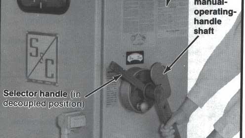
5 1 MANUAL OPERATON Before proceeding further, the user should become familiar with the operation of the manual operating handle and the selector handle as described on the switch operator nameplate on the right-hand side of the enclosure and in Steps 6, 7, and 8 below. See Figures 2 and 3. Step 6 To decouple: To permit electrical operation, testing or exercising of the switch operator without affecting the position of the Circuit-Switcher, or to permit manual operation of the Circuit-Switcher, an internal decoupling mechanism is provided. The selector handle, for external operation of the built-in internal decoupling mechanism, is located on the right-hand side of the switch operator enclosure. See Figure 2. Pull the latch knob to release the selector handle and rotate it counterclockwise approximately 100 degrees to the decoupled position. Release the latch knob to lock the handle in position. Moving the selector handle to its decoupled position releases the switch operator motor and gear train from the switch operator output shaft, and connects the manual-operatinghandle shaft to the output shaft. When the selector handle is in the decoupled position, the shunt-trip device (when this option is provided) is rendered inoperative.* Electrical testing of the operator may be performed in its decoupled position. Do not, however, operate electrically while the switch operator is in the coupled position until the adjustments described in Steps 9, 10, and 11 are completed. Visual inspection, through the observation window, will verify whether the internal decoupling mechanism is in the coupled or decoupled position. See Figure 3. The selector handle may be padlocked in either position. * Only the shunt-trip device is rendered inoperative. The switch operator can still be opened through the user s protective-relay circuit. Thus elective checkout of the system protective scheme is possible at any time..,.,. 1. L Clr&-Switchel rkhanlcal L posltton-indicatlng drum nternal decoupling - mechantsm (in coupled position) c Swftch operator mechanlcal posltlon-indl- catlng drum Observation *wndow al nternal,decouphng mechanism (in ld decoupled position) Selector handle (in coupled position) Figure 2. Selector nanale operatlon. Figure 3. Decoupling mechanism and mechanical position indicators. S&C ELECTRC COMPANY Chicago S&C ELECTRC CANADA LTD. Toronto NSTRUCTON SHEET Page 5 of 12 September 7,1993


6
7 1 MANUAL OPERATON - Continued Step 8 To couple: Determine the position of the switch operator output shaft, and the switch operator motor and gear train, by observing the mechanical positionindicating drums which appear in the two openings inside the enclosure at the upper left. See Figure 3. The upper drum is coupled to the switch operator output shaft. The green and red arrows on this drum indicate open and closed positions, respectively, of the Circuit-Switcher. The switch operator motor and gear train can be coupled to the Circuit-Switcher power train when they are in the same relative position as indicated by the matching pairs of green or red arrows. Approximate alignment of matching pairs of red or green arrows can be accomplished by manual operation of the Circuit-Switcher as explained in Step 6, or by electrical operation of the switch operator. When arrows are in approximate alignment, obtain precise alignment by turning the handwheel provided on the motor shaft. See Figure 5. Opening the handwheelaccess cover automatically releases the motor brake and opens the motor-contactor control circuit. When the matching pairs of red or green arrows are in precise alignment, pull the latch knob on the selector handle and rotate the handle clockwise. Release the latch knob to lock the selector handle in the coupled position. NSTRUCTON SHEET S&C ELECTRC COMPANY Page Chicago 7 of 12 S&C ELECTRC CANADA LTD. September Toronto 7,1993

, which governs the extent of output-shaft rotation in the opening and closing directions, includes six contacts that are operated by cam-actuated")
.")
 Remove the manual operating handle and move the cover for the manual-operating-handle shaft to the closed position. The selector handle itself must remain in the decoupled position.")

 To make this adjustment, lower the closing-stroke travel-limit disc (see Figure 6A) approximately 3/16 inch and rotate the disc clockwise to increase travel, or counterclockwise to decrease travel.")
8 S&C Switch Operators - Type CS-PA ADJUSTMENTS Be sure that the mechanics of coupling, decoupling, and manual operation, as explained in Steps 6, 7, and 8, are thoroughly understood. Now proceed with the adjustments of the travel-limit switch, as described in Steps 9, 10, and 11. To preclude possible damage to the power train, do not electrically operate the switch operator while the selector handle is in the coupled position until after completion of Step 11. The travel-limit switch (coupled to the motor), which governs the extent of output-shaft rotation in the opening and closing directions, includes six contacts that are operated by cam-actuated rollers. Positioning of the cams to properly engage the rollers is facilitated by the travel-limit discs (upper one is the openingstroke travel-limit disc; lower one is the closing-stroke travel-limit disc). step 9 Closing-stroke acijustxuent: (a) With the selector handle in the decoupled position, attach the manual operating handle and crank the Circuit-Switcher to itsfully closed position. (b) Remove the manual operating handle and move the cover for the manual-operating-handle shaft to the closed position. The selector handle itself must remain in the decoupled position. (c) Electrically operate the switch operator to open, and then to close. (d) Observe the red arrows on the upper and lower position-indicating drums. Adjust the travel-limit switch so that, at the completion of the closing stroke, the red arrows are vertically aligned. (Arrows will not necessarily be centered with respect to the openings through which they appear.) To make this adjustment, lower the closing-stroke travel-limit disc (see Figure 6A) approximately 3/16 inch and rotate the disc clockwise to increase travel, or counterclockwise to decrease travel. Then raise the disc and make sure it is engaged. Repeat the electrical open-close operations of the switch operator, and make disc adjustments as required, until vertical alignment of the red arrows is obtained. Step 10 Opening-stroke acijustment: (a) With the selector handle in the decoupled position, attach the manual operating handle and crank the Circuit-Switcher to its fully open position. (b) Remove the manual operating handle and move the cover for the manual-operating-handle shaft to the closed position. The selector handle itself must remain in the decuupled position. Figure 6A. Adjusting travel-limit switch. Figure 6B. Adjusting auxiliary switch. 7 lg15 10 NSTRUCTON SHEET Page 8 of 12 September 7,1993 S&C ELECTRC COMPANY Chicago S&C ELECTRC CANADA LTD. Toronto ---- _... -.

 To make this adjustment, raise the opening-stroke travel-limit disc (see Figure 6A) approximately 3/16 inch and rotate the disc clockwise to decrease travel, or counterclockwise to increase travel.")


.")
9 (c) Electrically operate the switch operator to close, and then to open. (d) Observe the green arrows on the upper and lower position-indicating drums. Adjust the travel-limit switch so that, at the completion of the opening stroke, the green arrows are vertically aligned. (Arrows will not necessarily be centered with respect to the openings through which they appear.) To make this adjustment, raise the opening-stroke travel-limit disc (see Figure 6A) approximately 3/16 inch and rotate the disc clockwise to decrease travel, or counterclockwise to increase travel. Then lower the disc and make sure it is engaged. Repeat the electrical close-open operations of the switch operator, and make disc adjustments as required, until vertical alignment of the green arrows is obtained. The preceding adjustments (Steps 9 and 10) were made to effect a close approximation of the proper travel of the switch operator. Those adjustments were a necessary preliminary to the precise adjustments described in Step 11, which will achieve complete opening and closing of the Circuit-Stitcher. Therefore, attention must now be directed to the drive-shaft cranks, located in each of the Circuit-Switcher poleunit bases, at the interphase shaft point. The driveshaft cranks may be observed through the open bottoms of the bases (with the perforated bottom panels removed). Step 11 Place the selector handle in the coupled position and operate the switch operator electrically to open and close the Circuit-Switcher. Observe the position of the Circuit-Switcher driveshaft cranks in both the open and closed positions. See Figure 7. The drive-shaft cranks are now not likely to reach their respective stops in either the open or closed position. This is because the travel-limit switch was adjusted to limit the motor travel in the decoupled (or no-load) condition. Drive-shaft crank Crank stops (bpen and closed) Figure 7. Drive-shaft crank stops on each Circuit-Switcher pole-unit. Slotted holes for precise positioning of arrow tabs Alignment arrows. Socket-head/ lock screws Figure 6. Resetting positlon-indicating drums. 7 NSTRUCTON SHEET S&C ELECTRC COMPANY Chicago Page 9 of 12 S&C ELECTRC CANADA LTD. Toronto September 7,1993

10 ~ S&C Switch Operators - Type CS-2A ADJUSTMENTS - Continued Carefully retard the travel-limit discs (asdescribed in Steps 9 and 10) to increase travel, in either the opening or closing direction as required, until the Circuit-Switcher drive-shaft cranks come to rest firmly against their corresponding stops in both the open and closed positions. Operate the Circuit-Switcher several times while making these final adjustments to ensure that the drive-shaft crank of each pole-unit attains a definite overtoggle stance in both the open and closed positions. As the drive-shaft cranks strike their stops, there should be no tendency to bounce. Bouncing indicates that the cranks on the three pole-units are not striking their stops simultaneously. Should this be observed, adjustment should be made in accordance with the Circuit-Switcher instruction sheet furnished. Step 12 Operate the switch operator electrically to close the Circuit-Switcher. Observe the red alignment arrows on the mechanical position-indicating drums. f these arrows are not in close vertical alignment, loosen the round-headed screws which secure the arrow tabs to the mechanical position-indicating drums, and adjust the arrow tabs as required to obtain vertical alignment (arrows need not be centered in the openings through which they appear). Tighten the round-headed screws. Operate the switch operator electrically to open the Circuit-Switcher. Adjust the green alignment arrows as described above. n the unlikely event that the adjustment range of the arrow tabs is not sufficient to obtain vertical alignment of the arrows, unbolt and remove the cover for the mechanical position-indicating drums and the decoupling mechanism. Open the two-pole motorcircuit disconnect switch. Then loosen the two sockethead lock screws located on the drums about two inches on either side of the red arrows. See Figure 8. Rotate the outer rings of the drums as required, and then tighten the socket-head lock screws. Replace the cover and make any further adjustments of the arrow tabs as described above. Step 13 The auxiliary switch, which is permanently coupled to the motor, includes eight contacts (terminals 11 through 26). (f the optional position-indicating lamps are included, six contacts are available.) These contacts are provided so that external circuits can be established to monitor switching operations. Each contact is operated by a cam-actuated roller. The cams are individually adjustable in 4.5-degree increments and can be positioned so that roller engagement occurs at the desired point in the operating cycle. The standard configuration for the auxiliary switch consists of four al contacts (terminals 11 through 18) and four bl contacts (terminals 19 through 26). Thus, with the switch operator in the open position, the al contacts are open and the bl contacts are closed. Conversely, with the switch operator in the closed position, the al contacts are closed and the bl contacts are open. Any auxiliary-switch contact being used must be checked for proper engagement a m the switchoperator travel-limit discs have been adjusted. Check the auxiliary-switch contacts for both the open and closed positions of the switch operator. To adjust the auxiliary-switch contacts, refer to Figure 6B and proceed as follows: (a) With the selector handle in the coupled position, operate the switch operator to the fully closed position. (b) Open the two-pole motor-circuit disconnect switch. (c) Determine which al contacts are not in the closed position. A contact is closed if its roller is disengaged from a cam and, conversely, a contact is open if its roller is engaged by a cam. (d)for the al contacts that are not in the closed position, raise (or lower) the corresponding cam toward its adjacent spring until the cam is separated from the teeth of the inner gear. Rotate the cam until it is in a position so that when lowered NSTRUCTON SHEET Page 10 of 12 S&C ELECTRC COMPANY Chicago September S&C 7,1993 ELECTRC LTD. CANADA Toronto
 the cam making sure that the teeth are in mesh with the inner gear and that the cam is disengaged from the roller. (e) Close the motor-circuit disconnect switch.")
11 ADJUSTMENTS - Continued (or raised) it will be disengaged from the roller. Lower (or raise) the cam making sure that the teeth are in mesh with the inner gear and that the cam is disengaged from the roller. (e) Close the motor-circuit disconnect switch. (f) Operate the switch operator to the fully open position. Open the motor-circuit disconnect switch and, if necessary, adjust the cams as described in (d) above until all bl contacts are in the closed position. (g) Close the motor-circuit disconnect switch and operate the switch operator. Both sets of contacts should now be correctly positioned for both open and closed positions of the Circuit-Switcher. Sufficient adjustment is available to provide correct positioning of both sets of contacts. Since each cam can be individually adjusted in 4.5-degree increments, any al contact can be changed to a bl contact, or vice versa. Also, because of the many positions to which the cams can be adjusted, the various rollers can be engaged or disengaged to respectively open or close their contacts simultaneously, sequentially, randomly, or in various combinations. Adjustment of the auxiliary switch for other than the standard contact configuration is left to the user. Remember that the motor-circuit disconnect switch should be open when adjusting these contacts. (Switch operators having catalog numbers with the suffi -Q are equipped with an extra auxiliary switch, terminals 27 through 34, having four contacts-two al and two b1 -which may be adjusted as described in (a) through (g) above. See Figure 6B.) step 14 Switch operators having catalog numbers with the suffi -W are equipped with an extra auxiliary switch which is permanently coupled to the Circuit-Switcher. The suffi -W auxiliary switch consists of eight contacts (terminals 35 through 50). These contacts are provided so that external circuits can be established to monitor Circuit-Switcher operation. Each contact is operated by a cam-actuated roller and the cams are individually adjustable in 4.5-degree increments. The standard configuration for the suffi -W extra auxiliary switch consists of four a2 contacts (terminals 35 through 42) and four b2 contacts (terminals 43 through 50). Thus, with the Circuit- Switcher in the fully closed position, the a2 contacts should be closed and the b2 contacts should be open. Conversely, with the Circuit-Switcher in the fully open position, the a2 contacts should be open and the b2 contacts should be closed. See Figure 6B. Any suffi -W auxiliary-switch contact being used must be checked for proper operation after satisfactory electrical operation of Circuit-Switcher has been achieved. Check the auxiliary-switch contact engagement for both the open and closed positions of the Circuit-Switcher. Adjustment of the suffix -W extra auxiliary switch is identical to the adjustment performed for the auxiliary switch and the suffw -Q extra auxiliary switch. Therefore, if adjustment of the suffi -W auxiliary switch is needed, refer to Step 13 and Figure 6B. 1 NSPECTON SCHEDULE AND PROCEDURES To assure continued proper performance of Circuit- Switcher and Type CS-2A Switch Operator, they should be inspected in accordance with S&C s recommended schedule and procedures contained in S&C nstruction Sheet (These procedures, incidentally, take the place of the annual exercising which has, up until the October 28,1985 issuance of nstruction Sheet , been recommended for Circuit-Switcher and its operator.) The Type CS-2A Switch Operator may be conveniently decoupled from the Circuit-Switcher, thereby permitting elective exercising of the operator at any time without requiring an outage or switching to an alternate source; when the switch operator is in the decoupled position, the shunt-trip device-if furnished-is rendered inoperative, thereby permitting checkout of the system protective scheme. NSTRUCTON SHEET 7 1 Q S&C ELECTRC COMPANY Page Chicago 11 of 12 S&C ELECTRC CANADA LTD. September Toronto 7,1993
12 SBC Switch Operators - Type CS-PA CHECKNG SWTCH OPERATOR AND CRCUT-SWTCHER POSTONS Do not assume that the switch operator position necessarily indicates the open or closed position of the Circuit-Switcher. Upon completion of an opening or closing operation (electrical or manual), check to be sure that the following conditions exist: 0 The mechanical position-indicating drums for both Circuit-Switcher and switch operator show a matched pair of green alignment arrows for a Circuit- Switcher open position, or a matched pair of red alignment arrows for a Circuit-Switcher closed position. See Figure 3. Also note the positionindicating lamps, Figure 1, if furnished. 0 The Circuit-Switcher disconnect blades on each poleunit are fully open or fully closed. Then tag and padlock the switch operator in accordance with standard system operating procedures. n all cases, make certain that the switch operator is padlocked before kalking away. Correct operation of the Circuit-Switcher depends on charging and latching the stored-energy source within each brain as the disconnect blades move to the fully open position and the interrupters close. The interrupter target located on the side of each brain housing appears yellow when the interrupters are open. The target appears gray (normal) when the interrupters are closed. Because the interrupters are closed as the Circuit- Switcher blades move to the fully open position, the target appears yellow only briefly during the opening operation. The target should not appear yellow when Circuit-Switcher is in the fully open or fully closed position. nterruptershould never be in the open (unlatched) position when the disconnect blades are in the closed position. To close the interrupters, Circuit-Switcher must be completely opened and then reclosed. For this reason, the switch operator incorporates a control circuit that causes it to return automatically to the open position whenever power is restored while the switch operator is at any position between fully open and fully closed. Such action takes place regardless of the direction in which the switch operator was operating prior to loss of voltage. This control circuit is a built-in safety feature to prevent Circuit-Switcher from being closed from a partially open position after the interrupters have tripped open. To restore to normal operation So that the switch operator is ready for normal operation of Circuit-Switcher by remote automatic or supervisory control, be sure that the following conditions exist: 0 The selector handle is in the coupled position. 0 The two-pole motor-circuit disconnect switch is closed. The switch operator is tagged and padlocked in accordance with standard system operating procedures. 71 Sm5 10 NSTRUCTON SHEET Page 12 of 12 September 7,1993 S&C ELECTRC COMPANY 0 Chicago S&C ELECTRC LTD. CANADA 0 Toronto
INSTRUCTIONS. 1 Schematic. I Device ' I. S8C Switch Operators - Type CS-24. For Operation
 Number 38840R1-B. The NSTRUCTON S8C Switch Operators - Type CS-24 NSTRUCTONS For Operation CAUTON: The equipment covered by this publication must be operated and maintained by qualified persons who are
INSTRUCTIONS. S&C Switch Operators - Type CS-1 A. For Operation INTRODUCTION
 S&C Switch Operators - Type CS-1 A NSTRUCTONS For Operation NTRODUCTON CAUTON: The equipment covered by this puelication must be operated and maintained by qualified persons who are thoroughly trained
S&C Switch Operators Types AS-1A and AS-10
 S&C Switch Operators Types AS-1A and AS-10 Page 1 of 11 S&C Switch Operators - Types AS-1A and AS-10 Types AS-1A and AS-10 Switch Operators are high-speed operators expressly designed for power operation
INSTRUCTIONS For Installation
 S&C Switch Operators - Types LS- and LS-2 NSTRUCTONS For nstallation TABLE OF CONTENTS i Section Page Number Section Page Number NTRODUCTON... 1 NSPECTON SCHEDULE AND PROCEDURES....16 NSTALLATON... 3 CHECKNG
Specifications. S&C Switch Operators Types AS-1A and AS-10a. Conditions of Sale
 a Specifications Conditions of Sale STANDARD: Seller s standard conditions of sale set forth in Price Sheet 150 apply. SPECIAL TO THIS PRODUCT: INCLUSIONS: S&C Switch Operators Types AS-1A and AS-10 are
INSTRUCTIONS. S&c Circuit-Switchers - Mark v Grounding Switches - 70,000 Amperes Momentary Outdoor Transmission I INTRODUCTION INSTRUCTION SHEET 7 1 1
 S&c Circuit-Switchers - Mark v Grounding Switches - 70,000 Amperes Momentary With 90-degree opening blades NSTRUCTONS - - - - - - - - - - - - - - For Field Assembly and nstallation NTRODUCTON CAUTON: The
INSTRUCTIONS. Operating Lever4 Maximum Operating
 S&C Switch Operators - Type CS-10 NSTRUCTONS 1 NTRODUCTON CAUTON: The equipment covered by this publication must be operated and maintained by qualified persons who are thoroughly trained and who understand
INSTRUCTIONS For Field Assembly and Installation
 S&C Line-Rupters" Outdoor Transmission (115 kv through 230 kv) I For Line and Cable Switching INSTRUCTIONS For Field Assembly and Installation ITABLE OF CONTENTS I Section Page Number Section Page Number
I TABLE OF CONTENTS I INTRODUCTION. S&C Switch Operators - Type AS-1A. Qualified Persons. For Installation
 S&C Switch Operators - Type AS-1A For nstallation TABLE OF CONTENTS Section Page Number NTRODUCTON... 1 SAFETY NFORMATON LJnderst,anding Safety-Alert Messages.... 4 Following Safety nstructions... 4 Replacement
INSTRUCTIONS For Field Assembly and Installation
 nteger Style NSTRUCTONS For Field Assembly and nstallation [TABLE OF CONTENTS Section Page Number Section Page Number NTRODUCTON... 1 NSTALLATON... 7 BEFORE STARTNG NSTALLATON....5 FNA1,CHECKS... 10 1
Horizontal Circuit Switchers
 > Transformer Protection > CIRCUIT SWITCHERS C A T A L O G B U L L E T I N General Application Southern States Types CSH and CSH-B Horizontal Circuit Switchers provide an economical, versatile, space saving
Horizontal Circuit Switchers
 > Transformer Protection > CIRCUIT SWITCHERS C A T A L O G B U L L E T I N General Application Southern States Types CSH and CSH-B Horizontal Circuit Switchers provide an economical, versatile, space saving
Instructions for Installation
 S&C Circuit-Switchers Mark VI Outdoor Transmission 69 kv through 138 kv Option U, User-Furnished Mounting Structure Instructions for Installation TABLE OF CONTENTS Section Page Section Page INTRODUCTION
Installation. S&C Circuit-Switchers Mark VI 69-kV 51-inch Phase Spacing Single Pedestal Design Outdoor Transmission.
 S&C Circuit-Switchers Mark VI 69-kV 51-inch Phase Spacing Single Pedestal Design Outdoor Transmission Installation Table of Contents Section Page Section Page Introduction Qualified Persons....2 Read this
Interrupter Replacement INSTRUCTIONS. For Replacement of Interrupters. A Cypo.qdated is the S&C trademark for devices employing the S&C Cypoxfl
 - - - S&C Alduti-Rupters Switches* Outdoor and ndoor Distribution nterrupter Replacement NSTRUCTONS - ~~~ - ~~ ~~ For Replacement of nterrupters [TABLE OF CONTENTS Page Section Section Number Page NTRODUCTON...
INSTRUCTIONS For Field Assembly and Installation
 S%C Circuit-Switchers - Mark V Outdoor Transmission Vertical-Break Style 34.5 kv through 161 kv NSTRUCTONS For Field Assembly and nstallation TABLE OF CONTENTS Section Page Number Section Page Number NTRODUCTON....l
S&C Vista Underground Distribution Switchgear
 S&C Vista Underground Distribution Switchgear Pad-Mounted, Vault-Mounted, and UnderCover Styles Instructions For Installation and Operation of Portable Motor Operator TABLE OF CONTENTS Section Page Section
Instructions for Installation and Operation
 S&C Alduti-Rupter Switches Outdoor Distribution Three-Pole Vertical-Break Style Reciprocating Operating Mechanism 25/34.5 kv and 34.5 kv Instructions for Installation and Operation TABLE OF CONTENTS Section
INSTRUCTIONS. Section Page Number Section Page Number REMOVING THE MECHANICAL ANTIPARALLELING S&C ELECTRIC COMPANY 0 Chicago
 SBC Source-Transfer PMH Pad-Mounted Gear Outdoor Distribution (14.4 kv and 25 kv) Replacing Type AT-1 2 Control With Micro-AT Control n Gear Having Rl or R2 Supplement to the Catalog Number TABLE OF CONTENTS
PAD-MOUNT SWITCHGEAR 15kV 25kV 35kV
 PAGE 1 TYPE PSI PAD-MOUNT SWITCHGEAR 15kV 25kV 35kV INSTRUCTIONS For Installation and Operation INTRODUCTION... 1 Receiving... 1 Handling... 1 Storage... 1 GENERAL DESCRIPTION... 1 SAFETY FEATURES... 1
Introduction CAUTION. S&C Power Operated Metal-Enclosed Switchgear Outdoor Distribution (4.16 kv, through 34.5 kv)
") S&C Power Operated Metal-Enclosed Switchgear Outdoor Distribution (4.16 kv, through 34.5 kv) Inspection Recommendations for Switchgear with Type AT-3 Source- Transfer Controls Table of Contents Section
S&C Power Operated Metal-Enclosed Switchgear Outdoor Distribution (4.16 kv, through 34.5 kv) Inspection Recommendations for Switchgear with Type AT-3 Source- Transfer Controls Table of Contents Section
Instructions for Installation and Operation
 S&C Alduti-Rupter Switches Three-Pole Side-Break Heavy-Duty Style Reciprocating Operating Mechanism 34.5 kv Instructions for Installation and Operation TABLE OF CONTENTS Section Page Section Page INTRODUCTION
S&C Mini-Rupter Switches Application The Standard Mounting Arrangement Scheme for S&C Mini-Rupter Switches Typical ED, reduced from full 11 size.
 S&C Mini-Rupter es Indoor Distribution (4.16 kv through 25 kv) Selecting Standard Mounting Arrangements for Manually Operated Styles Application The Standard Mounting Arrangement Scheme for S&C Mini-Rupter
Introduction CAUTION CAUTION. S&C Power Operated Metal-Enclosed Switchgear Indoor and Outdoor Distribution (4.16 through 34.5 kv)
") S&C Power Operated Metal-Enclosed Switchgear Indoor and Outdoor Distribution (4.16 through 34.5 kv) Inspection Recommendations for Switchgear Equipped with Type AT-2 Source-Transfer Controls Table of Contents
S&C Power Operated Metal-Enclosed Switchgear Indoor and Outdoor Distribution (4.16 through 34.5 kv) Inspection Recommendations for Switchgear Equipped with Type AT-2 Source-Transfer Controls Table of Contents
S&C Circuit-Switchers Mark VI Installed on S&C Mounting Pedestals 84- through 102-inch Phase Spacing Outdoor Transmission (69 kv through 138 kv)
") S&C Circuit-Switchers Mark VI Installed on S&C Mounting Pedestals 84- through 102-inch Phase Spacing Outdoor Transmission (69 kv through 138 kv) Installation Table of Contents Section Page Section Page
S&C Circuit-Switchers Mark VI Installed on S&C Mounting Pedestals 84- through 102-inch Phase Spacing Outdoor Transmission (69 kv through 138 kv) Installation Table of Contents Section Page Section Page
INSTRUCTIONS I INTRODUCTION I TABLE OF CONTENTS. %!kc TypeAT-2,TypeAT-3,orTypeAT-12Source- S8C Type AT Source-Transfer Controls I Field Replacement
 S8C Type AT Source-Transfer Controls Field Replacement NSTRUCTONS TABLE OF CONTENTS Section Page Number Section Page Number NTRODUCTON... 1 RE LACNG TYPE AT-2 SOURCE-TRANSFER CONTROL N REPLACNG TYPE AT-2
Typical Specification
 Engineered to Order Built to Last Typical Specification VAULT VRPFI, TWO POSITION, ROTARY PUFFER SWITCHGEAR PART 1- GENERAL 1.1 DESCRIPTION A. The switch shall consist of manually operated load interrupting,
DESIGN GUIDELINES LOW VOLTAGE SWITCHGEAR PAGE 1 of 5
 DESIGN GUIDELINES LOW VOLTAGE SWITCHGEAR PAGE 1 of 5 1.1. APPLICABLE PUBLICATIONS 1.1.1. Publications listed below (including amendments, addenda, revisions, supplements, and errata), form a part of this
SPECIFICATION BULLETIN
 SPECIFICATIONS Conditions of Sale STANDARD: Seller s standard conditions of sale set forth in Price Sheet 150 apply, except as modified under WARRANTY QUALIFICATIONS on page 3. SPECIAL TO THIS PRODUCT:
Three-Phase Pole Mounted Recloser
 Three-Phase Pole Mounted Recloser Page 1 of 8 Table of Contents 1 GENERAL... 3 2 CONSTRUCTION... 3-5 3 BUSHINGS... 5 4 LINE CONNECTOR... 5 5 TOOLS....5 6 NAMEPLATES..6 7 PAINT... 6 8 EXTERNAL HARDWARE
Indoor or Outdoor 2400 to 14,400 Volts 600 to 14,400 Kvac, 3 Phase, 60 Hz
 c February, 1979 Supersedes DB 39-485, pages 1-4, dated November, 1973 Mailed to: E, D, C/2001, 2002/DB Benefits There are many capacitor applications in which factors such as physical location, personnel
Installation Instructions For Motor Control Center (MCC) Units
 Units") s Page 1 of 8 Installation Instructions December, 2013 Installation Instructions For Motor Control Center (MCC) Units Hazardous voltage. Will cause death or serious injury. Always de-energize and ground
s Page 1 of 8 Installation Instructions December, 2013 Installation Instructions For Motor Control Center (MCC) Units Hazardous voltage. Will cause death or serious injury. Always de-energize and ground
ME Switchgear with Vacuum Circuit Breaker and Auto-jet II Switch with Ground Position
 LET S BE PACIFIC November 0 Volume Number 5 ME Switchgear with Vacuum Circuit Breaker and Auto-jet II Switch with Ground Position Federal Pacific has the capability to engineer, fabricate and assemble
S&C Manual PME Pad-Mounted Gear
 S&C Manual PME Pad-Mounted Gear Outdoor Distribution,. kv and 5 kv S&C Manual PME Pad-Mounted Gear... Featuring Elbow-Connected Encased Components. S&C Manual PME Pad-Mounted Gear brings in-air insulation,
SUBSTATION VACUUM CIRCUIT BREAKER (15.5KV)
") SUBSTATION VACUUM CIRCUIT BREAKER (15.5KV) For more than four decades, Myers Power Products has led the switchgear market in quality for the electric industry, delivering highly reliable products for utilities
SUBSTATION VACUUM CIRCUIT BREAKER (15.5KV) For more than four decades, Myers Power Products has led the switchgear market in quality for the electric industry, delivering highly reliable products for utilities
SUBSTATION VACUUM CIRCUIT BREAKER (38KV)
") SUBSTATION VACUUM CIRCUIT BREAKER (38KV) For more than four decades, Myers Power Products has led the switchgear market in quality for the electric industry, delivering highly reliable products for utilities
SUBSTATION VACUUM CIRCUIT BREAKER (38KV) For more than four decades, Myers Power Products has led the switchgear market in quality for the electric industry, delivering highly reliable products for utilities
SUBSTATION VACUUM CIRCUIT BREAKER (25.8 / 27KV)
") SUBSTATION VACUUM CIRCUIT BREAKER (25.8 / 27KV) For more than four decades, Myers Power Products has led the switchgear market in quality for the electric industry, delivering highly reliable products
SUBSTATION VACUUM CIRCUIT BREAKER (25.8 / 27KV) For more than four decades, Myers Power Products has led the switchgear market in quality for the electric industry, delivering highly reliable products
The steering column is of a modular construction and features easy to service electrical switches.
 file://c:\tso\tsocache\vdtom_5368\svk~us~en~file=svkb4a01.htm~gen~ref.htm Page 1 of 3 Section 11-04A: Steering Column, Ranger DESCRIPTION AND OPERATION 1997 Ranger Workshop Manual Steering Column NOTE:
www. ElectricalPartManuals. com
 Instructions for Parcel-Line Type DH-P Circuit Breakers with Post Insulator Type Pole Units (Supplements I. B. 32-253-2) Westinghouse Electric Corporation Switchgear Division, East Pittsburgh, Pa. 15112
Cleaning Flooded Gear
 S&C Manual PMX Modular Metal-Enclosed Switchgear Outdoor Distribution (13.8 kv and 25 kv) Cleaning Flooded Gear Table of Contents Section Page Section Page Introduction.... 2 Safety Information Understanding
S&C Series 2000 Circuit-Switchers Outdoor Transmission 69 kv through 230 kv
 S&C Series 2000 Circuit-Switchers Outdoor Transmission 69 kv through 230 kv Why do power users choose the Series 2000 Circuit-Switcher over any other circuit-switcher? Series 2000 Circuit-Switcher advances
Series 70 24V On/Off Electric Actuator Operation and Maintenance Manual
 Series 70 Operation and Maintenance Manual TABLE OF CONTENTS 1. Definition of Terms............................................. 1 2. Safety................................................... 1 3. Storage..................................................
INSTRUCTIONS For Field Replacement
 SLC Source-Transfer PMH Pad-Mounted Gear Outdoor Distribution (14.4 kv and 25 kv) Replacing Type AT-12 Control With Micro-ATT Control In Gear Having R4 Supplement to the Catalog Number INSTRUCTIONS For
www. ElectricalPartManuals. com INSTRUCTIONS "INERTEEN AND OIL INSULATED FEEDER SWITCHES DESCRIPTION INSTALLATION MAINTENANCE
 r \ FIG. 1. Cutaway View of Typical Switch. I.L. 46-723-1 DESCRIPTION INSTALLATION MAINTENANCE INSTRUCTIONS THE INERTEEN AND OIL INSULATED FEEDER SWITCH provides complete switching facilities in a minimum
COOPER POWER SERIES. Types D and DV recloser installation instructions. Reclosers MN280030EN
 Reclosers MN280030EN Effective December 2015 Supersedes S280-20-1 February 1979 Types D and DV recloser installation instructions COOPER POWER SERIES DISCLAIMER OF WARRANTIES AND LIMITATION OF LIABILITY
INSTRUCTIONS I INTRODUCTION. S&C Switches Indoor Distribution (4.8 kv through 34.5 kv) I INSTRUCTION SHEET
 I INSTRUCTION SHEET") S&C Alduti-Rupter@ Switches ndoor Distribution (4.8 kv through 34.5 kv) NSTRUCTONS For nstallation NTRODUCTON CAUTON: The equipment covered by this publication mustbeselected for a specific application
S&C Alduti-Rupter@ Switches ndoor Distribution (4.8 kv through 34.5 kv) NSTRUCTONS For nstallation NTRODUCTON CAUTON: The equipment covered by this publication mustbeselected for a specific application
Replacement of 600-Ampere Bushing and 200-Ampere Bushing-Well Adapters
 S&C Vista SD Underground Distribution Switchgear Pad-Mounted and Vault-Mounted Style Outdoor Distribution (17.5 kv and 29 kv) With Visi-Gap Load Interrupter Switches and Visi-Gap Fault Inetrrupters Replacement
Vacuum Circuit Breaker Type VAD-3
 Instruction Bulletin Bulletin 6055-11 Vacuum Circuit Breaker Type VAD-3 4.76 kv, 29 ka (250 MVA) 4.76 kv, 41 ka (350 MVA) 8.25 kv, 33 ka (500 MVA) 15.0 kv, 18 ka (500 MVA) 15.0 kv, 28 ka (750 MVA) 15,0
Reproduction or other use of this Manual, without the express written consent of Vulcan, is prohibited.
 SERVICE MANUAL ELECTRIC BRAISING PANS (30 & 40 GALLON) VE30 VE40 ML-126849 ML-126850 VE40 SHOWN - NOTICE - This Manual is prepared for the use of trained Vulcan Service Technicians and should not be used
Surepowr Series 100 Installation Manual
 Surepowr Series 100 Installation Manual Safety First In the maintenance and operation of mechanical equipment, safety is the basic factor which must be considered at all times. Through the use of the proper
ABB Automation, Inc. Substation Automation & Protection Division Coral Springs, FL Allentown, PA
 ABB Automation, Inc. Substation Automation & Protection Division Coral Springs, FL Allentown, PA Instruction Leaflet I.L. 41-661.1B Effective: June 1997 Supersedes I.L. 41-661.1A, Dated February 1994 Type
Publication No.: PSG
 TABLE OF CONTENTS PAGE 1.0 SCOPE...2 2.0 STANDARDS...2 3.0 DESIGN REQUIREMENTS...2 3.01 Service Conditions... 2 3.02 Ratings... 3 3.03 Resistors... 3 3.04 Interrupter... 4 3.05 SF 6 Gas System... 4 3.06
Installation and Operation
 S&C Omni-Rupter Switches Outdoor Distribution 14.4 kv and 25 kv Three-Pole Side-Break Integer Style Hookstick-Operated Vertical and Tiered-Outboard Mounting Configurations Installation and Operation Table
TM-1620 OPERATING INSTRUCTIONS AND OWNERS MANUAL
 TM-1620 OPERATING INSTRUCTIONS AND OWNERS MANUAL tracopackaging.com 800-284-WRAP 620 SOUTH 1325 WEST OREM, UT. PHONE 800-284-WRAP (9727) IMPORTANT: READ ALL INSTRUCTIONS BEFORE OPERATING EQUIPMENT Your
C. Figure 1. CA-16 Front View Figure 2. CA-16 Rear View
 Figure 1. CA-16 Front View Figure 2. CA-16 Rear View 2 2.1. Restraint Elements Each restraint element consists of an E laminated electromagnet with two primary coils and a secondary coil on its center
Westinghouse Electric Corporation Distribution and Control Business Unit Assemblies Division Bloomington, Indiana
 Supersedes Descriptive Bulletin, pages 1-8, dated January, 1976 Mailed to: E, D, C/38-000F Westinghouse Electric Corporation Distribution and Control Business Unit Assemblies Division Bloomington, Indiana
Cleaning Flooded Gear
 S&C Manual Metal-Enclosed Switchgear Indoor and Outdoor Distribution (4.16 kv through 34.5 kv) Cleaning Flooded Gear Table of Contents Section Page Section Page Introduction.... 2 Safety Information Understanding
Your Global Flow Control Partner. Series 70 24V On/Off Electric Actuator Operation and Maintenance Manual
 Your Global Flow Control Partner Series 70 Table of Contents 1. Definition of Terms.......................................2 2. Safety............................................. 2 3. Storage............................................2
WARNING. TYPE PSI/II PAD-MOUNT SWITCHGEAR with Non-Loadbreak Fuse Mountings 15kV 25kV INSTRUCTIONS. Qualified Persons. For Installation and Operation
 PAGE 1 TYPE PSI/II PAD-MOUNT SWITCHGEAR with Non-Loadbreak Fuse Mountings 15kV 25kV QUALIFIED PERSONS...1 SAFETY INFORMATION...2 INTRODUCTION...3 Receiving...3 Handling...3 Storage...3 GENERAL DESCRIPTION...3
Installation and Operation
 S&C Series 2000 Circuit-Switchers Outdoor Transmission Model 2030 With Vertical Interrupters and Without Disconnect 69 kv through 230 kv Installation and Operation Table of Contents Section Page Section
SUREPOWR TM SERIES -SURE 49 FIELD INSTALLATION INSTRUCTIONS
 SUREPOWR TM SERIES -SURE 49 FIELD INSTALLATION INSTRUCTIONS Safety First In the maintenance and operation of mechanical equipment, SAFETY is the basic factor which must be considered at all times. Through
Power & High Voltage Joslyn Hi-Voltage Overhead Reclosers & Switches H-220. Series HVI Hi-Velocity Interrupter Attachment
 Use load interrupter attachments to enable loop sectionalizing, line dropping, load breaking and transformer-magnetizing current interruption. Increase the capability of your disconnect switches by adding
ABB Power T&D Company Inc. Relay Division Coral Springs, FL Allentown, PA. Non-Directional, Single Phase Adjustable Time Delay Device No.
 September, 1990 Supersedes Descriptive Bulletin 41-100, pages 1-4, dated June, 1989 Mailed to: E, D, C/41-100A Hi-Lo co induction-disc type overcurrent relays are activated when the current in them exceeds
Valtek Auxiliary Handwheels and Limit Stops
 Valtek Auxiliary s and Limit Stops Table of Contents Page 1 General information 2 Installation 2 Side-mounted handwheels, size 25 and 50 (linear actuators) 3 Side-mounted handwheels, size 100 and 200 (linear
SUREPOWR TM SERIES -SURE 24/25 FIELD INSTALLATION INSTRUCTIONS
 SUREPOWR TM SERIES -SURE 4/5 FIELD INSTALLATION INSTRUCTIONS Safety First In the maintenance and operation of mechanical equipment, SAFETY is the basic factor which must be considered at all times. Through
INSTRUCTIONS For Installation
 S&C Mini-Rupter@Switches ndoor Distribution (4.16 kv through 25 kv) NSTRUCTONS For nstallation NTRODUCTON CAUTON: The equipment covered by this publication mustbeselected for a specific application and
ProTrip Conversion Kits. For GE Types AK-15, AK-25, and AKU- 25 Low-Voltage Power Circuit Breakers INTRODUCTION. DEH Installation Instructions
 DEH 40026 Installation Instructions g ProTrip Conversion Kits For GE Types AK-15, AK-25, and AKU- 25 Low-Voltage Power Circuit Breakers INTRODUCTION GE Conversion Kits are designed for upgrading existing
TYPE PSI/II PADMOUNT SWITCHGEAR 15KV 25KV
 Cutler Hammer SECTION PB-1A-110 PAGE 1 Replaces April, 1996 TYPE PSI/II PADMOUNT SWITCHGEAR 15KV 25KV The PSI/II Padmount is the second generation of switchgear in the PSI switchgear family. The PSI/II
Descriptive bulletin. Medium voltage load interrupter switchgear Reliable, low maintenance and economical for distribution applications
 Descriptive bulletin Medium voltage load interrupter switchgear Reliable, low maintenance and economical for distribution applications General overview Reliable, low maintenance and economical Load Interrupter
Digitrip Retrofit System for ITE K-3000, K-3000 S, K-4000 and K-4000 S Breakers
 Supersedes IL 33-858-4 Dated 05/02 Digitrip Retrofit System for ITE K-3000, K-3000 S, K-4000 and K-4000 S Breakers Digitrip Retrofit System for ITE K-3000, Digitrip Retrofit System for ITE K-3000, K-3000
ROLLER GATES. Waterman Industries of Egypt. Roller gates are nominated for heavy duty service where large loads and sizes are going to be encountered.
 ROLLER GATES Roller Gates are ideally suited for controlling water in any large openings such as may be found in power plants, water and sewage treatment facilities, flood control projects, irrigation
S&C Type FVR Substation Circuit Breaker
 S&C Type FVR Substation Circuit Breaker 15 kv to 38 kv, 200 kv BIL, 1200 A, Class 6065 Instructions for Installation 60553014 S&C ELECTRIC COMPANY Specialists in Electric Power Switching and Protection
VOLTAGE CONNECTOR CORCOM S VOLTAGE SELECTING AND FUSED CONNECTOR
 IMCO.US MADE IN USA VOLTAGE CONNECTOR CORCOM S VOLTAGE SELECTING AND FUSED CONNECTOR Developed for the manufacturer who markets his products worldwide, the Voltage Connector eliminates the need for internal
Installation. S&C Omni-Rupter Switches Outdoor Distribution 14.4 kv and 25 kv
 S&C Omni-Rupter Switches Outdoor Distribution 14.4 kv and 25 kv Three-Pole Side-Break Integer Style Hookstick-Operated Vertical and Tiered-Outboard Mounting Configurations Catalog Number Supplement R3
OPERATION INSTRUCTONS MODEL SG 05.1 SG Quarter-Turn Actuators
 OPERATION INSTRUCTONS MODEL SG 05.1 SG 12.1 Quarter-Turn Actuators AUMA Actuators, Inc. USA 100 Southpointe Boulevard Canonsburg, PA 15317 724-743-2862 Fax: 724-743-4711 www.auma-usa.com email: mailbox@auma-usa.com
COOKSON OWNER'S MANUAL
 COOKSON OWNER'S MANUAL FDO-A10 INDUSTRIAL DUTY FIRE DOOR OPERATOR R L I S T E D 3040233 US CONTROL PANEL SERIAL# OPERATOR SERIAL# 9001.DWG ECN 0959 REV 4 SPECIFICATIONS MOTOR TYPE:...INTERMITTENT HORSEPOWER:...1/8
SecoVac * Ground & Test Device
 GE Industrial Solutions DEH-50007 Installation, Operation and Maintenance Manual SecoVac * Ground & Test Device For 5kV-15kV IEEE Metal-clad Switchgear Table of Contents 1. Introduction...6 Safety Precautions...6
TRINETICS CSD SERIES OIL SWITCH INSTALLATION INSTRUCTIONS
 TRINETICS CSD SERIES OIL SWITCH INSTALLATION INSTRUCTIONS 33220900 DECEMBER 2011 Caution: The equipment covered by these installation instructions should be installed and serviced only by properly trained
ichards MANUFACTURING COMPANY, SALES, INC. 517 LYONS AVENUE, IRVINGTON, NJ Phone Fax
 Network Protector Instruction Manual Type 316NP ichards MANUFACTURING COMPANY, SALES, INC. 517 LYONS AVENUE, IRVINGTON, NJ 07111 Phone 973-371-1771 Fax 973-371-9538 IM 1232-001B DISCLAIMER OF WARRANTIES
IB PowlVac ITE-HK Remote Racking Device
 IB-51802 PowlVac ITE-HK Remote Racking Device for use with ITE-HK 5kV & 15kV Circuit Breakers and PowlVac ITE-HK 5kV & 15kV Replacement Circuit Breakers Powered by Safety PowlVac ITE-HK Remote Racking
THE BULLETIN 509 ASSEMBLY GUIDE - Features and Benefits
 m 5 PRODUCT BULLETIN w DATA 509 I THE BULLETIN 509 ASSEMBLY GUIDE - and Publication 509-2.1 -June, 1990 Supersedes Publication MC- 130 Dated September, 1979 Allen-Bradley quality is more than a slogan.
Installation Instructions
 Page 6300-S-1 Installation Instructions 1. Read complete instructions before proceeding and do not discard packing materials until any/all loose items are located. Also, make sure that the installation
SL-6 & SL-6A. I UNION SWITCH & SIGNAL l[ml 645 Russell Street Batesburg, SC Service Manual Field and Shop Maintenance
 I UNION SWITCH & SIGNAL l[ml 645 Russell Street Batesburg, SC 29006 Service Manual 3011 SL-6 & SL-6A Outlying Switch Lock Field and Shop Maintenance April, 1979 A-79-500-1496-3 1979, Union Switch & Signal
TRI-SERVICE ELECTRICAL WORKING GROUP (TSEWG) 03/05/09 TSEWG TP-11: UFC N BEST PRACTICES
 03/05/09 TSEWG TP-11: UFC N BEST PRACTICES") TSEWG TP-11: UFC 3-500-10N BEST PRACTICES UFC 3-500-10N was developed by NAVFAC and was used as the starting point for the tri-services development of UFC 3-500-10, Design: Electrical Engineering. UFC
TSEWG TP-11: UFC 3-500-10N BEST PRACTICES UFC 3-500-10N was developed by NAVFAC and was used as the starting point for the tri-services development of UFC 3-500-10, Design: Electrical Engineering. UFC
Installation And Operation
 S&C Series 2000 Circuit-Switchers Outdoor Transmission Model 2020 With Vertical Interrupters and Side-Break Power-Operated Disconnect 69 kv through 138 kv Installation And Operation Table of Contents Section
SAVE THESE INSTRUCTIONS FOR FUTURE REFERENCE IMPORTANT SAFEGUARDS READ AND FOLLOW ALL SAFETY INSTRUCTIONS
 Champ Fluorescent Luminaires DMVFB Auxiliary Series - 52, 64, & 84 Watt Installation & Maintenance Information SAVE THESE INSTRUCTIONS FOR FUTURE REFERENCE IF 1713 IMPORTANT SAFEGUARDS READ AND FOLLOW
The EFL 2000/1 & 2 User Guide Test Sieve Shaker. Contents
 The EFL 2000/1 & 2 User Guide Test Sieve Shaker ISSUE 04-02 Contents Description Page 1 Setting Up: 2-8 Unpacking 2 Assembly 3 Clamping Assembly 4 Electrical Connections 5 Sieve Stacking 6 8 Operating
CITY OF LOMPOC UTILITIES DEPARTMENT ELECTRICAL DIVISION SPECIFICATION NO. ELE-112 SUBSTATION CLASS VACUUM CIRCUIT BREAKERS OCTOBER 2008
 CITY OF LOMPOC UTILITIES DEPARTMENT ELECTRICAL DIVISION SPECIFICATION NO. ELE-112 SUBSTATION CLASS VACUUM CIRCUIT BREAKERS OCTOBER 2008 SPECIFICATION NO: ELE_112_R1.doc Page 1 of 3 Rev. 10/28/2008 SPECIFICATION
Installation and Service Instructions for Self Adjust Brakes 81,000 Series
 Spring-Set Disc Brakes P/N -07-9-00 effective 07/0/0 Installation and Service Instructions for Self Adjust Brakes,000 Series Current revision available @ www.stearns.rexnord.com Tools required for installation
2.0 CONSTRUCTION AND OPERATION 3.0 CHARACTERISTICS K. CO (HI-LO) Overcurrent Relay
 Overcurrent Relay") 41-100K 2.0 CONSTRUCTION AND OPERATION The type CO relays consist of an overcurrent unit (CO), either an Indicating Switch (ICS) or an ac Auxiliary Switch (ACS) and an Indicating Instantaneous Trip unit
41-100K 2.0 CONSTRUCTION AND OPERATION The type CO relays consist of an overcurrent unit (CO), either an Indicating Switch (ICS) or an ac Auxiliary Switch (ACS) and an Indicating Instantaneous Trip unit
MODEL 520 REMOTE START ENGINE MANAGEMENT SYSTEM
 MODEL 520 REMOTE START ENGINE MANAGEMENT SYSTEM DSE 520 ISSUE 4 4/4/02 MR 1 TABLE OF CONTENTS Section Page INTRODUCTION... 4 CLARIFICATION OF NOTATION USED WITHIN THIS PUBLICATION.... 4 1. OPERATION...
Heavy Duty Miniature Quick-Change Applicator (Side-Feed Type) with Mechanical or Air Feed Systems
 with Mechanical or Air Feed Systems") Heavy Duty Miniature Quick-Change Applicator (Side-Feed Type) with Mechanical or Air Feed Systems Instruction Sheet 408-8040 30 NOV 17 Rev H Ram Assembly Ram Post Locking Screw Stock Drag Drag Release
Heavy Duty Miniature Quick-Change Applicator (Side-Feed Type) with Mechanical or Air Feed Systems Instruction Sheet 408-8040 30 NOV 17 Rev H Ram Assembly Ram Post Locking Screw Stock Drag Drag Release
Product Specification Guide. Title: Southern States 362 kv RLSwitcher Vertical Interrupter Style Reactor Switcher
 TABLE OF CONTENTS PAGE 1.0 SCOPE... 2 2.0 STANDARDS... 2 3.0 DESIGN REQUIREMENTS... 2 3.01 Service Conditions... 2 3.02 Ratings... 2 3.03 Interrupter... 3 3.04 SF6 Gas System... 4 3.05 Terminal Pads...
S&C Circuit-Switcher Mark VI Outdoor Transmission (69 kv through 138 kv)
") Outdoor Transmission (69 kv through 138 kv) Construction Guide This publication sets forth the data required for the user to design a support structure or pedestals for a Mark VI Circuit-Switcher; the
Outdoor Transmission (69 kv through 138 kv) Construction Guide This publication sets forth the data required for the user to design a support structure or pedestals for a Mark VI Circuit-Switcher; the
C1000 Series Automatic Cap Bank
 C1000 Series Automatic Cap Bank Metal Enclosed - Medium Voltage Capacitors Assemblies Fixed / Auto Medium Voltage 5, 15, 25 and 35 kv Class Customized to your specifications The Reactive Power Solution
OPERATIONS/PARTS MANUAL FOR PATTERSON'S WWP40E P-L/R ELECTRIC WINCH.
 DOC # A0000298 / A0000299 Patterson Company 870 Riversea Road Pittsburgh, PA 15233 Phone: 800-322-2018 FAX: 412-322-2785 OPERATIONS/PARTS MANUAL FOR PATTERSON'S WWP40E-7.5-14-208-P-L/R ELECTRIC WINCH.
Specifications. S&C Mini-Rupter Switches Indoor Distribution (4.16 kv through 25 kv) Manually Operated Styles
 Manually Operated Styles") Indoor Distribution (4.16 kv through 25 kv) Manually Operated Styles Specifications Conditions of Sale STANDARD: Seller s standard conditions of sale set forth in Price Sheet 150 apply, except as modified
Indoor Distribution (4.16 kv through 25 kv) Manually Operated Styles Specifications Conditions of Sale STANDARD: Seller s standard conditions of sale set forth in Price Sheet 150 apply, except as modified
ELECTRICAL GROUNDING SAFETY PROGRAM
 ELECTRICAL GROUNDING SAFETY PROGRAM PURPOSE / SCOPE The purpose of this program is to ensure the proper installation, maintenance, inspection, and testing of equipment grounding conductors on construction
Instruction Bulletin. Jockey Pump Controller
 Instruction Bulletin Jockey Pump Controller Installation Start Up Service This instruction bulletin is a guide for personnel involved with maintenance, engineering and approval of Fire Pump equipment and
1ZSC ABH en, Rev. 1. Motor-drive mechanisms, types BUE and BUL2 Maintenance guide
 1ZSC000498-ABH en, Rev. 1 Motor-drive mechanisms, types BUE and BUL2 Maintenance guide Original instruction The information provided in this document is intended to be general and does not cover all possible