INDEX UNIT- IV MECHANISM FOR CONTROL (1) Introduction (2) Principle of Working (3) Classification of governors (4) Height of governor (5) Sleeve lift
|
|
|
- Abraham Phelps
- 5 years ago
- Views:
Transcription
1 INDEX UNIT- IV MECHANISM FOR CONTROL (1) Introduction (2) Principle of Working (3) Classification of governors (4) Height of governor (5) Sleeve lift (6) Isochronism s (7) Stability (8) Hunting (9) Sensitiveness (10) Characteristics and qualities of centrifugal governor (11) Watt governor (12) Porter governor (13) Proell governor (14) Hartnell governor (15) Hartung governor (16) Wilson Hartnell governor (17) Pickering governor (18) Difference between a flywheel and a governor (19) Gyroscope (20) Description and diagram (2 1) Effect of the Gyroscopic Couple on an Aero plane (22) Effect of gyroscopic couple (23) Effect of gyroscopic couple on ship (24) Effect of Gyroscopic Couple on a Naval Ship during pitching (25) Effect of Gyroscopic couple on a Naval Ship during Rolling (26) Effect of Gyroscopic couple on a 4 - wheel drive (27) Example Problems 1
 admitted, so as to maintain a near constant speed whatever the load or fuel supply conditions. It uses the principle of proportional control.")
2 Governor (1) Introduction: UNIT- IV MECHANISM FOR CONTROL A centrifugal governor is a specific type of governor that controls the speed of an engine by regulating the amount of fuel (or working fluid) admitted, so as to maintain a near constant speed whatever the load or fuel supply conditions. It uses the principle of proportional control. It is most obviously seen on steam engines where it regulates the admission of steam into the cylinder(s). It is also found on internal combustion engines and variously fuelled turbines, and in some modern striking clocks. (2) Principle of Working: Power is supplied to the governor from the engine's output shaft by (in this instance) a belt or chain (not shown) connected to the lower belt wheel. The governor is connected to a throttle valve that regulates the flow of working fluid (steam) supplying the prime mover (prime mover not shown). As the speed of the prime mover increases, the central spindle of the gover nor r otates at a faster rate and the kinetic energy of the balls increases. This allows the two masses on lever arms to move outwards and upwards against gravity. If the motion goes far enough, this motion causes the lever ar ms to pull down on a thrust bearing, which moves a beam linkage, which reduces the aperture of a throttle valve. The rate of working-fluid entering the cylinder is thus reduced and the speed of the pr ime mover is controlled, preventing over speeding. Mechanical stops may be used to limit the range of throttle motion, as seen near the masses in the image at right. 2
 Classification of governors: Governors are classified based upon two different principles. These are: 1. Centrifugal governors 2.")
3 The direction of the lever arm holding the mass will be along the vector sum of the reactive centrifugal force vector and the gravitational force. (3) Classification of governors: Governors are classified based upon two different principles. These are: 1. Centrifugal governors 2. Inertia governors Centrifugal governors are further classified as (4) Height of governor It is the vertical distance between the centre of the governor halls and the point of intersection between the upper arms on the axis of spindle is known as governor height. It is generally denoted by h. (5) Sleeve lift The vertical distance the sleeve travels due to change in the equilibrium Speed is called the sleeve lift. The vertical downward travel may be termed as Negative lift (6) Isochronism s This is an extreme case of sensitiveness. When the equilibrium speed is constant for all radii of rotation of the balls within the working range, the governor is said to be in isochronism s. This means that the difference between the maximum and minimum equilibrium speeds is zero and the sensitiveness shall be infinite. (7) Stability Stability is the ability to maintain a desired engine speed without Fluctuating. Instability results in hunting or oscillating due to over correction. Excessive stability results in a dead-beat governor or one that does not correct sufficiently for load changes. 3

4 (8) Hunting The phenomenon of continuous fluctuation of the engine speed above and below the mean speed is termed as hunting. This occurs in over- sensitive or isochronous governors. Suppose an isochronous governor is fitted to an engine running at a steady load. With a slight increase of load, the speed will fall and the sleeve will immediately fall to its lowest position. This shall open the control valve wide and excess supply of energy will be given, with the result that the speed will rapidly increase and the sleeve will rise to its higher position. As a result of this movement of the sleeve, the control valve will be cut off; the supply to the engine and the speed will again fall, the cycle being repeated indefinitely. Such a governor would admit either more or less amount of fuel and so effect would be that the engine would hunt. (9) Sensitiveness A governor is said to be sensitive, if its change of speed s from no Load to full load may be as small a fraction of the mean equilibrium speed as possible and the corresponding sleeve lift may be as large as possible. Suppose 1 = max. Equilibrium speed 2 = min. equilibrium speed = mean equilibrium speed = ( 1+ 2)/2 Therefore sensitiveness = ( 1-2)/2 (10) Characteristics and qualities of centrifugal governor: For satisfactory performance and working a centrifugal governor should possess The following qualities. a. On the sudden r emoval of load its sleeve should reach at the top most position at Once. b. Its response to the change of speed should be fast.. Its sleeve should float at some intermediate position under normal operating Conditions. d. At the lowest position of sleeve the engine should develop maximum power. e. It should have sufficient power, so that it may be able to exert the required force At the sleeve to operate the control & mechanism (11) Watt governor: 4
5 The simplest form of a centrifugal governor is a Watt governor, as shown in Fig. It is basically a conical pendulum with links attached to a sleeve of negligible mass. The arms of the governor may be connected to the spindle in the following three ways: 1. The pivot P, may be on the spindle axis as shown in Fig. (a). 2. The pivot P, may be offset from the spindle axis and the arms when produced intersect at O, as shown in Fig. (b). 3. The pivot P, may be offset, but the arms cross the axis at O, as shown in Fig. (c). Let m = Mass of the ball in kg, w = Weight of the ball in Newton s = m.g, T = Tension in the arm in Newton s, ω = Angular velocity of the arm and ball about the spindle axis in rad/s, r = Radius of the path of rotation of the ball i.e. horizontal distance from the centre of the ball to the spindle axis in meter s, FC = Centrifugal force acting on the ball in Newton s = m.ω2.r, and h = Height of the governor in meter s. It is assumed that the weight of the arms, links and the sleeve are negligible as compared to the weight of the balls. Now, the ball is in equilibrium under the action ofhe centrifugal force (FC) acting on the ball, 2. The tension (T) in the arm, 3. The weight (w) of the ball. Taking moments about point O, we have FC h = w r = m.g.r or m.ω2.r.h = m.g.r or h = g /ω2... (i) When g is expressed in m/s2 and ω in rad/s, then h is in metres. If N is the speed in r.p.m., then ω = 2π N/60 Note: We see from the above expression that the height of a governor h, is inversely proportional to N2. Therefore at high speeds, the value of h is small. At such speeds, the change in the value of h corresponding to a small change in speed is insufficient to enable a governor of this type to operate the mechanism to give the necessary change in the fuel supply. This governor may only work satisfactorily at relatively low speeds i.e. from 60 to 80 r.p.m. 5

6 (12) Porter governor The Porter governor is a modification of a Watt s governor, with central load attached to the sleeve as shown in Fig. (a). The load moves up and down the central spindle. This additional downward force increases the speed of revolution required to enable the balls to rise to any predetermined level. Consider the forces acting on one-half of the governor as shown in Fig. (b). Let m = Mass of each ball in kg, w = Weight of each ball in Newton s = m.g, M = Mass of the central load in kg, W = Weight of the central load in Newton s = M.g, r = Radius of rotation in metres, h = Height of governor in metres, N = Speed of the balls in r.p.m., ω = Angular speed of the balls in rad/s ω = 2π N/60rad/s, Though there are several ways of determining the relation between the height of the governor (h) and the angular speed of the balls ( ), yet the following two methods are important from the subject point of view : 1. Method of resolution of forces ; and 2. Instantaneous centre method. 6

 The weight of ball (w = m.")
7 1. Method of resolution of forces Considering the equilibrium of the forces acting at D, we have Again, considering the equilibrium of the forces acting on B. The point B is in equilibrium under the action of the following forces, as shown in Fig (b). (i) The weight of ball (w = m.g), (ii) The centrifugal force (FC), (iii) The tension in the arm (T1), and (iv) The tension in the link (T2). Resolving the forces vertically, 7
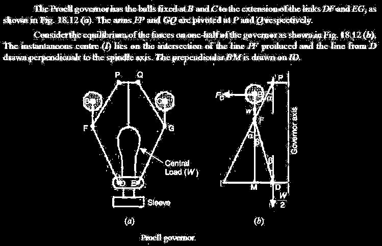
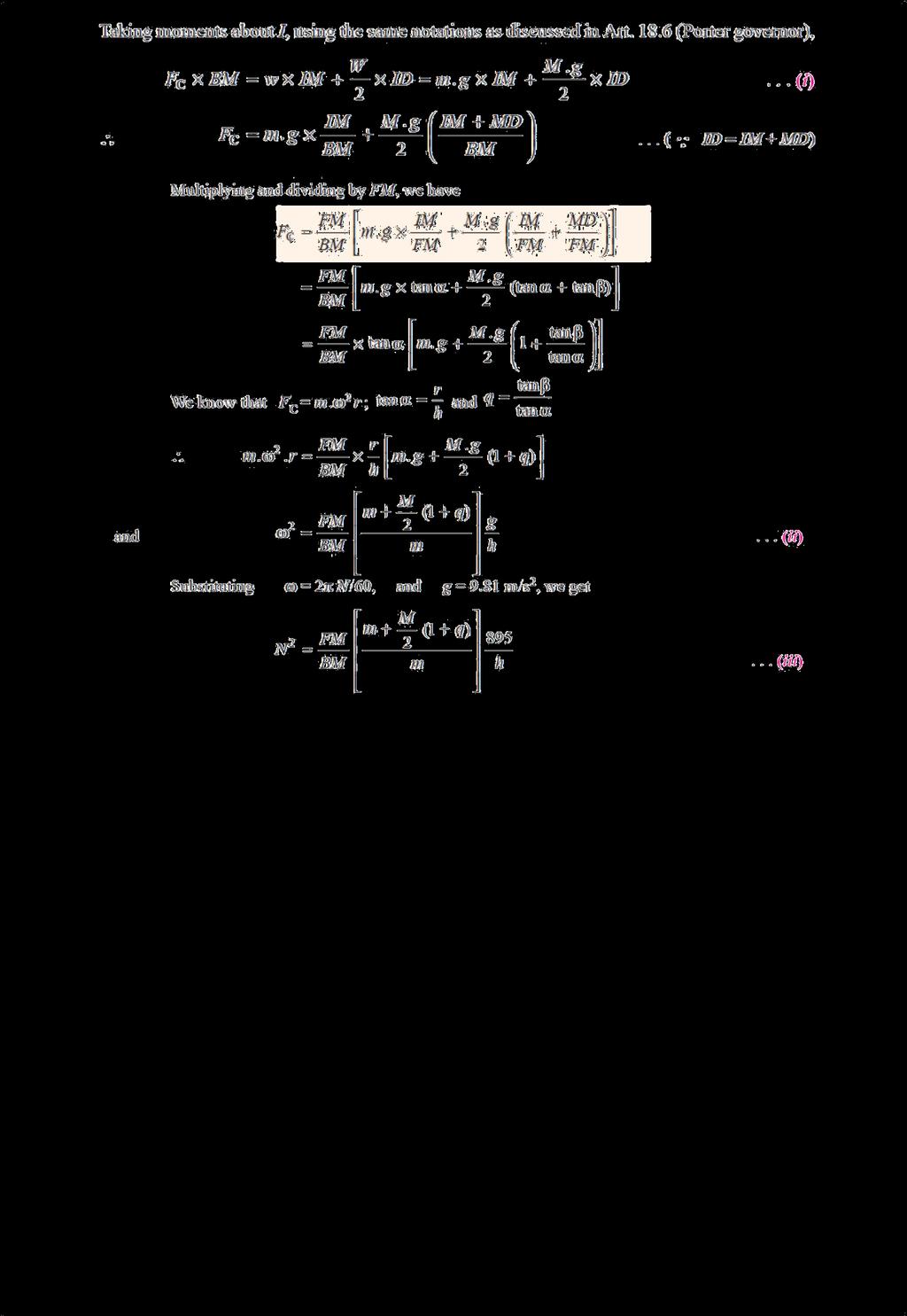
8 (13)Proell governor: 8

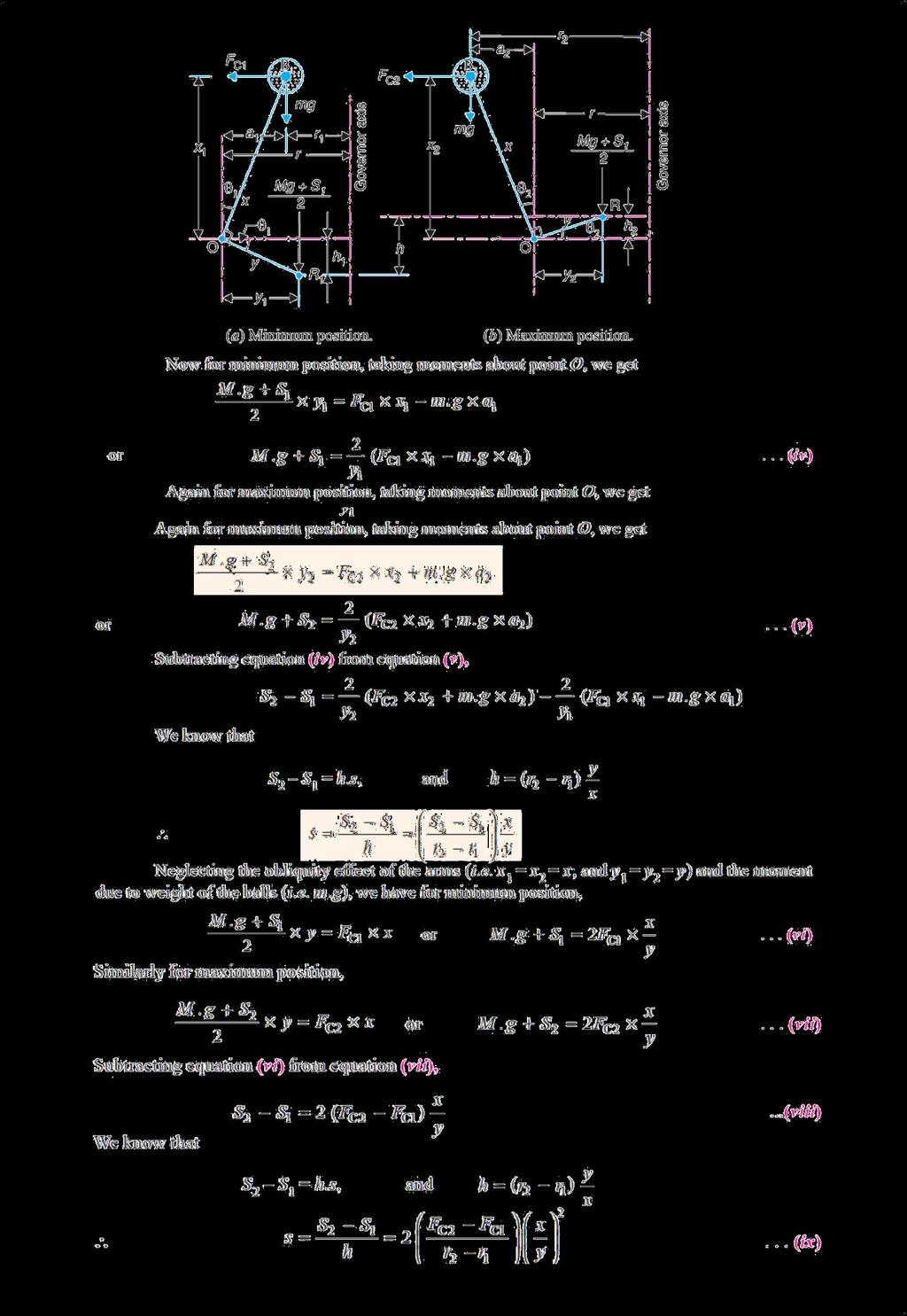
9 (14) Hartnell governor: A Hartnell governor is a spring loaded governor as shown in Fig It consists of two bell crank levers pivoted at the points O,O to the frame. The frame is attached to the governor spindle and therefore rotates with it. Each lever carries a ball at the end of the vertical arm OB and a roller at the end of the horizontal arm OR. A helical spring in compression provides equal downward forces on the two rollers through a collar on the sleeve. The spring force may be adjusted by screwing a nut up or down on the sleeve. Let m = Mass of each ball in kg, M = Mass of sleeve in kg, r1 = Minimum radius of rotation in metres, r2 = Maximum radius of rotation in metres, ω1 = Angular speed of the governor at minimum radius in rad/s, ω2 = Angular speed of the governor at maximum radius in rad/s, S1 = Spring force exerted on the sleeve at ω1 in Newton s, S2 = spring force exerted on the sleeve at ω2 in Newton s, FC1 = Centrifugal force at ω1 in Newton s = m (ω1)2 r1, FC2 = Centrifugal force at ω2 in Newton s = m (ω2)2 r2, s = Stiffness of the spring or the force required to compress the spring by one mm, x = Length of the vertical or ball arm of the lever in metres, y = Length of the horizontal or sleeve arm of the lever in metres, and r = Distance of fulcrum O from the governor axis or the radius of rotation when the governor is in mid-position, in metres. 9
, the compression of the spring or the lift of sleeve h1 is given by 10")
10 Consider the forces acting at one bell crank lever. The minimum and maximum position is shown in Fig. Let h be the compression of the spring when the radius of rotation changes from r1 to r2. For the minimum position i.e. when the radius of rotation changes from r to r1, as shown in Fig (a), the compression of the spring or the lift of sleeve h1 is given by 10
11 11
.")

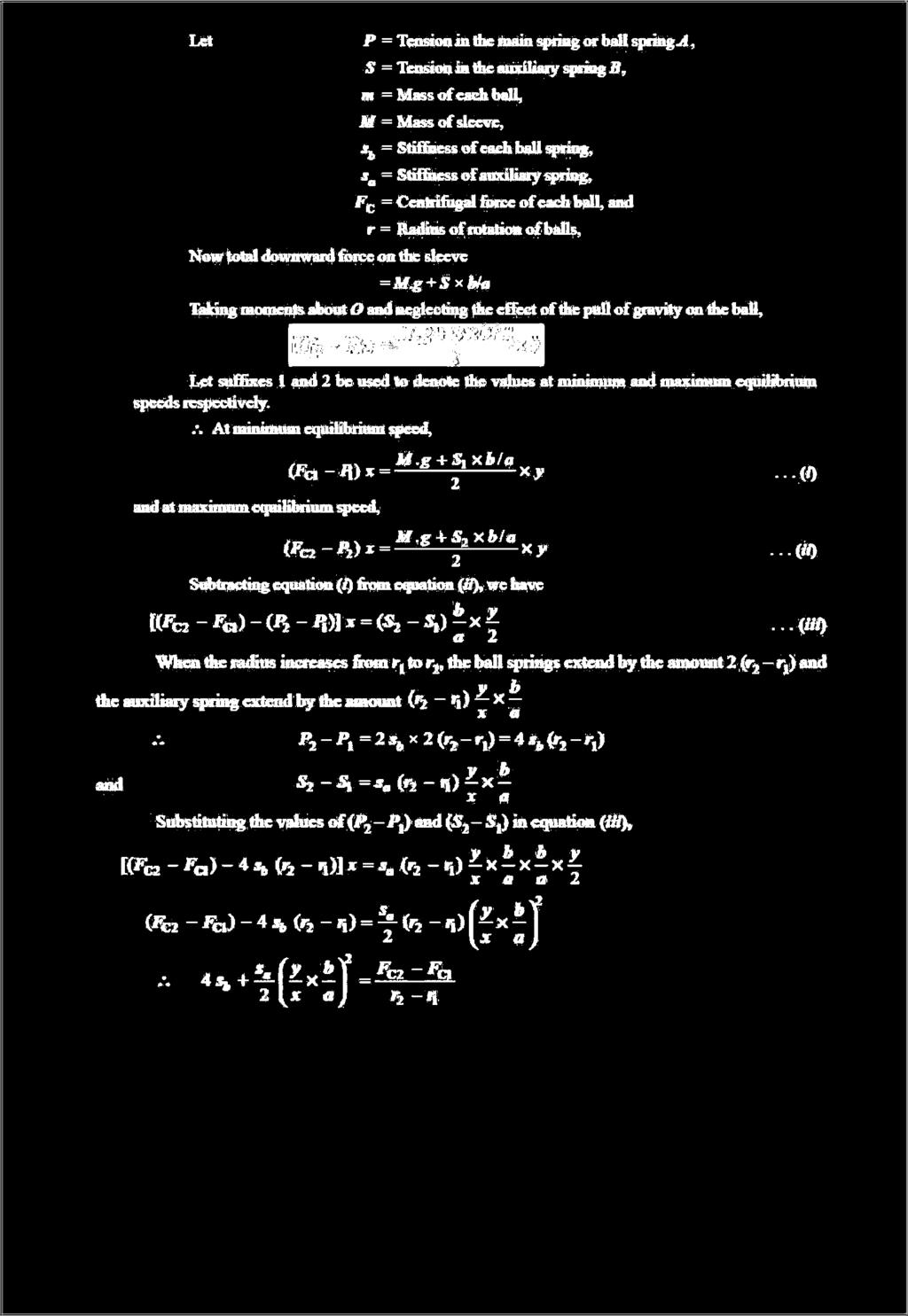
12 (15) Hartung governor: A spring controlled governor of the Hartung type is shown in Fig (a). In this type of governor, the vertical arms of the bell crank levers are fitted with spring balls which compress against the frame of the governor when the rollers at the horizontal arm press against the sleeve. (16) Wilson Hartnell governor: 12
13 13

14 (17) Pickering governor: 14

15 (19) Gyroscope A gyroscope is a device for measuring or maintaining orientation, based on the principles of conservation of angular momentum. A mechanical gyroscope is essentially a spinning wheel or disk whose axle is free to take any orientation. This orientation changes much less in response to a given external torque than it would without the large angular momentum associated with the gyroscope's high rate of spin. Since external torque is minimized by mounting the device in gimbals, its orientation remains near ly fixed, regardless of any motion of the platform on which it is mounted. Gyroscopes based on other operating principles also Exit, such as the electronic, microchip-packaged MEMS gyroscope devices found in consumer electronic devices, solid state ring laser s, fiber optic gyroscopes and the extremely sensitive quantum gyroscope. Applications of gyroscopes include navigation (INS) when magnetic compasses do not work (as in the Hubble telescope) or are not precise enough (as in ICBMs) or for the stabilization of flying vehicles like radio-controlled helicopters or UAVs. Due to higher precision, gyroscopes are also used to maintain direction in tunnel mining. (20) Description and diagram: Diagram of a gyro wheel. Reaction arrows about the output axis (blue) correspond to forces applied about the input axis (green), and vice versa. Within mechanical systems or devices, a conventional gyroscope is a mechanism comprising a rotor journal led to spin about one axis, the journals of the rotor being mounted in an inner gimbal or ring, the inner gimbal is journal led for oscillation in an outer gimbal which is jour nal led in another gimbal. So basically there ar e three gimbals. The outer gimbal or ring which is the gyroscope frame is mounted so as to pivot about an axis in its own plane determined by the support. This outer gimbal possesses one degree of rotational fr eedom and its axis possesses none. The next inner gimbal is mounted in the gyroscope frame (outer gimbal) so as to pivot about an axis in its own plane that is always perpendicular to the pivotal axis of the gyr oscope frame (outer gimbal). This inner gimbal has two degrees of rotational fr eedom. Similarly, next innermost gimbal is attached to the inner gimbal which has 15

16 three degree of rotational freedom and its axis posses two. The axle of the spinning wheel defines the spin axis. The rotor is journeyed to spin about an axis which is always perpendicular to the axis of the innermost gimbal. So, the rotor possesses four degrees of rotational freedom and its axis possesses three. The wheel responds to a force applied about the input axis by a reaction force about the output axis. The behavior of a gyroscope can be most easily appreciated by consideration of the front wheel of a bicycle. If the wheel is leaned away from the vertical so that the top of the wheel moves to the left, the forward rim of the wheel also turns to the left. In other words, rotation on one axis of the turning wheel produces rotation of the third axis. (21) Effect of the Gyroscopic Couple on an Aeroplane (22) EFFECT OF GYROS COPIC COUPLE This couple is, therefore, to raise the nose and dip the tail of the aero plane. Notes1. When the aero plane takes a right turn under similar Conditions as discussed above, the effect of the reactive Couple will be to dip the nose and raise the tail of the aero plane. 2. When the engine or propeller rotates in anticlockwise direction when viewed from the rear or tail end and the aero plane takes a left turn, then the effect of reactive gyroscopic couple will be to dip the nose and raise the tail of the aero plane. 16

17 3. When the aero plane takes a right turn under similar Conditions as mentioned in note 2 above, the effect of Reactive gyroscopic couple will be to raise the nose and dip the of the aero plane. 4. When the engine or propeller rotates in clockwise direction when viewed from the front and the aero plane takes a left turn, then the effect of reactive gyr oscopic couple will be to raise the tail and dip the nose of the aero plane. 5. When the aero plane takes a right turn under similar conditions as mentioned in note4 above, the effect of reactive gyroscopic couple will be to raise the nose and dip the tail of the aero plane. (23) Effect of gyroscopic couple on ship The top and front views of a naval ship are shown in fig. The for e end of the ship is called bow and the rear end is known as ster n or aft. The left hand and the right hand sides of the ship, when viewed from the stern are called port and star board respectively. We shall now discuss the effect of gyroscopic couple in the naval ship in the following three cases: 1. Steering 2. Pitching, and 3. Rolling 17
18 (24) Effect of Gyroscopic Couple on a Naval Ship during Steering and pitching Steering is the turning of a complete ship in a curve towards left or right, while it moves forward, considers the ship taking a left turn, and rotor rotates in the clockwise direction when viewed from the stern, as shown in Fig. below. The effect of gyroscopic couple on a naval ship during steering taking left or right turn may be obtained in the similar way as for an aero plane as discussed in Art. When the rotor of the ship rotates in the clockwise direction when viewed from the stern, it will have its angular momentum vector in the direction ox as shown in Fig. A1. As the ship steers to the left, the active gyroscopic couple will change the angular momentum vector from ox to ox. The vector xx now represents the active gyroscopic couple and is perpendicular to ox. Thus the plane of active gyroscopic couple is perpendicular to xx and its direction in the axis OZ for left h and tu rn is clockwise as shown in Fig below. The reactive gyroscopic couple of the same magnitude will act in the opposite direction (i.e in anticlockwise direction). The effect of this reactive gyroscopic couple is to raise the bow and lower the stern. Notes 1. When the ship steers to the right under similar condition as discussed above, the effect of the reactive gyroscopic couple, as shown in Fig. B1, will be to raise the stern and lower the bow. 2. When the rotor rotates in the anticlockwise direction, when viewed from the stern and the ship is steering to the left, then the effect of reactive gyroscopic couple will be to lower the bow and raise the stern. 3. When the ship is steering to the right under similar conditions as discussed in note 2 above, then the effect of reactive gyroscopic couple will be to raise the bow and lower the stern. 4. When the rotor rotates in the clockwise direction when viewed from the bow or fore end and the ship is steering to the left, then the effect of reactive gyroscopic couple will be to raise the stern and lower the bow. 5. When the ship is steering to the righ t under similar conditions as discussed in note 4 above, then the effect of reactive gyroscopic couple will be to raise the bow and lower the stern. 18
19 6. The effect of the reactive gyroscopic couple on a boat propelled by a turbine taking left or right turn. (25) Effect of Gyroscopic Couple on a Naval Ship during Rolling: We know that, for the effect of gyroscopic couple to occur, the axis of precession should always be perpendicular to the axis of spin. If, however, the axis of pr ecession becomes parallel to the axis of spin, there will be no effect of the gyroscopic couple acting on the body of the ship. In case of rolling of a ship, the axis of precession (i.e. longitudinal axis) is always parallel to the axis of spin for all positions. Hence, there is no effect of the gyroscopic couple acting on the body of a ship. 19
Introduction. Types of Governors. The governors may, broadly, be classified as. 1. Centrifugal governors, and 2. Inertia governors.
 TOM Governor Assi. Professor Mechanical Engineering Department Introduction The function of a governor is to regulate the mean speed of an engine, when there are variations in the load e.g. when the load
UNIT - III GYROSCOPE
 UNIT - III GYROSCOPE Introduction 1When a body moves along a curved path, a force in the direction of centripetal acceleration (centripetal force ) has to be applied externally This external force is known
VTU EDUSAT PROGRAMME -17 DYNAMICS OF MACHINES (10 ME 54) Unit-7 ADARSHA H G GYROSCOPE
 Unit-7 ADARSHA H G GYROSCOPE") VTU EDUSAT PROGRAMME -17 DYNAMICS OF MACHINES (10 ME 54) 1.0 INTRODUCTION Unit-7 GYROSCOPE Gyre is a Greek word, meaning circular motion and Gyration means the whirling motion. A gyroscope is a spatial
VTU EDUSAT PROGRAMME -17 DYNAMICS OF MACHINES (10 ME 54) 1.0 INTRODUCTION Unit-7 GYROSCOPE Gyre is a Greek word, meaning circular motion and Gyration means the whirling motion. A gyroscope is a spatial
B.TECH III Year I Semester (R09) Regular & Supplementary Examinations November 2012 DYNAMICS OF MACHINERY
 Regular & Supplementary Examinations November 2012 DYNAMICS OF MACHINERY") 1 B.TECH III Year I Semester (R09) Regular & Supplementary Examinations November 2012 DYNAMICS OF MACHINERY (Mechanical Engineering) Time: 3 hours Max. Marks: 70 Answer any FIVE questions All questions
1 B.TECH III Year I Semester (R09) Regular & Supplementary Examinations November 2012 DYNAMICS OF MACHINERY (Mechanical Engineering) Time: 3 hours Max. Marks: 70 Answer any FIVE questions All questions
III B.Tech I Semester Supplementary Examinations, May/June
 Set No. 1 III B.Tech I Semester Supplementary Examinations, May/June - 2015 1 a) Derive the expression for Gyroscopic Couple? b) A disc with radius of gyration of 60mm and a mass of 4kg is mounted centrally
R10 Set No: 1 ''' ' '' '' '' Code No: R31033
 R10 Set No: 1 III B.Tech. I Semester Regular and Supplementary Examinations, December - 2013 DYNAMICS OF MACHINERY (Common to Mechanical Engineering and Automobile Engineering) Time: 3 Hours Max Marks:
LABORATORY MANUAL DYNAMICS OF MACHINE LAB
 LABORATORY MANUAL DYNAMICS OF MACHINE LAB Sr. No Experiment Title 1 To Perform Experiment On Watt And Porter Governors To Prepare Performance Characteristic Curves, And To Find Stability & Sensitivity
smartworld.asia UNIT III Clutches: Friction clutches- Single Disc or plate clutch, Multiple Disc Clutch, Cone Clutch, Centrifugal Clutch.
 SYLLABUS UNIT I PRECESSION : Gyroscopes, effect of precession motion on the stability of moving vehicles such as motor car, motor cycle, aero planes and ships. Static and dynamic force analysis of planar
MLR Institute oftechnology
 MLR Institute oftechnology Dundigal, Hyderabad - 500 043 MECHANICAL ENGINEERING Assignment Questions DYNAMICS OF MACHINERY Course Title Course Code 55012 Regulation R13 Course Structure Lectures Tutorials
Jahangirabad Institute Of Technology Assistant Prof. MD Gulfaraz Alam Dynamics of Machines Semester VI, MASTER SCHEDULE. Monday, January 18
 Jahangirabad Institute Of Technology Assistant Prof. MD Gulfaraz Alam Dynamics of Machines Semester VI, 2015-16 MASTER SCHEDULE Class 1 Monday, January 18 Unit-I Introduction Week 1 Class 3 Wednesday,
Theory of Machines. CH-1: Fundamentals and type of Mechanisms
 CH-1: Fundamentals and type of Mechanisms 1. Define kinematic link and kinematic chain. 2. Enlist the types of constrained motion. Draw a label sketch of any one. 3. Define (1) Mechanism (2) Inversion
INSTITUTE OF AERONAUTICAL ENGINEERING (Autonomous) Dundigal, Hyderabad
 Dundigal, Hyderabad") INSTITUTE OF AERONAUTICAL ENGINEERING (Autonomous) Dundigal, Hyderabad -500 043 MECHANICAL ENGINEERING TUTORIAL QUESTION BANK Course Name Course Code Class Branch : DYNAMICS OF MACHINERY : A50317 : III
INSTITUTE OF AERONAUTICAL ENGINEERING (Autonomous) Dundigal, Hyderabad -500 043 MECHANICAL ENGINEERING TUTORIAL QUESTION BANK Course Name Course Code Class Branch : DYNAMICS OF MACHINERY : A50317 : III
Machines and mechanisms
 Machines and mechanisms Contents: 1. Basics and Kinematics of Mechanism 2. Cam and Follower 3. Governor 4. Gear and Gear Train 5. Inertia Force Analysis Basics and Kinematics Mechanism: 1. A rigid body
SYLLABUS. osmania university. Force Analysis of Four-Bar and Slider Crank Mechanisms. CHAPTER - 2 : DYNAMIC FORCE ANALYSIS
 Contents i SYLLABUS osmania university UNIT - I CHAPTER - 1 : STATIC TIC FORCE ANALYSIS Force Analysis of Four-Bar and Slider Crank Mechanisms. CHAPTER - 2 : DYNAMIC FORCE ANALYSIS Force Analysis of Four-Bar
Chapter 15. Inertia Forces in Reciprocating Parts
 Chapter 15 Inertia Forces in Reciprocating Parts 2 Approximate Analytical Method for Velocity and Acceleration of the Piston n = Ratio of length of ConRod to radius of crank = l/r 3 Approximate Analytical
St.MARTIN S ENGINEERING COLLEGE Dhulapally, Secunderabad
 St.MARTIN S ENGINEERING COLLEGE Dhulapally, Secunderabad-500 014 Subject: Kinematics of Machines Class : MECH-II Group A (Short Answer Questions) UNIT-I 1 Define link, kinematic pair. 2 Define mechanism
B.Tech. MECHANICAL ENGINEERING (BTMEVI) Term-End Examination December, 2012 BIMEE-007 : ADVANCED DYNAMICS OF MACHINE
 Term-End Examination December, 2012 BIMEE-007 : ADVANCED DYNAMICS OF MACHINE") No. of Printed Pages : 5 BIMEE-007 B.Tech. MECHANICAL ENGINEERING (BTMEVI) Term-End Examination 01601 December, 2012 BIMEE-007 : ADVANCED DYNAMICS OF MACHINE Time : 3 hours Maximum Marks : 70 Note : Attempt
No. of Printed Pages : 5 BIMEE-007 B.Tech. MECHANICAL ENGINEERING (BTMEVI) Term-End Examination 01601 December, 2012 BIMEE-007 : ADVANCED DYNAMICS OF MACHINE Time : 3 hours Maximum Marks : 70 Note : Attempt
DYNAMICS LABORATORY. AIM: To apply the knowledge gained in kinematics and dynamics of machines to real system.
 DYNAMICS LABORATORY AIM: To apply the knowledge gained in kinematics and dynamics of machines to real system. OBJECTIVES: To supplement the principles learnt in kinematics and Dynamics of Machinery. To
Chapter 15. Inertia Forces in Reciprocating Parts
 Chapter 15 Inertia Forces in Reciprocating Parts 2 Approximate Analytical Method for Velocity & Acceleration of the Piston n = Ratio of length of ConRod to radius of crank = l/r 3 Approximate Analytical
Moments. It doesn t fall because of the presence of a counter balance weight on the right-hand side. The boom is therefore balanced.
 Moments The crane in the image below looks unstable, as though it should topple over. There appears to be too much of the boom on the left-hand side of the tower. It doesn t fall because of the presence
The University of Melbourne Engineering Mechanics
 The University of Melbourne 436-291 Engineering Mechanics Tutorial Twelve General Plane Motion, Work and Energy Part A (Introductory) 1. (Problem 6/78 from Meriam and Kraige - Dynamics) Above the earth
Simple Gears and Transmission
 Simple Gears and Transmission Simple Gears and Transmission page: of 4 How can transmissions be designed so that they provide the force, speed and direction required and how efficient will the design be?
INDEX. UNIT I - Force Analysis
 INDEX UNIT I - Force Analysis (1) Introduction (2) Newton s Law (3) Types of force Analysis (4) Principle of Super Position (5) Free Body Diagram (6) D Alemberts Principle (7) Dynamic Analysis of Four
FRICTION DEVICES: DYNAMOMETER. Presented by: RONAK D. SONI Assistant Professor Parul Institute of Technology, Parul University
 FRICTION DEVICES: DYNAMOMETER Presented by: RONAK D. SONI Assistant Professor Parul Institute of Technology, Parul University DYNAMOMETER A dynamometer is a brake but in addition it has a device to measure
Code No: R Set No. 1
 Code No: R05310304 Set No. 1 III B.Tech I Semester Regular Examinations, November 2007 KINEMATICS OF MACHINERY ( Common to Mechanical Engineering, Mechatronics, Production Engineering and Automobile Engineering)
Simple Gears and Transmission
 Simple Gears and Transmission Contents How can transmissions be designed so that they provide the force, speed and direction required and how efficient will the design be? Initial Problem Statement 2 Narrative
2. a) What is pantograph? What are its uses? b) Prove that the peaucellier mechanism generates a straight-line motion. (5M+10M)
 What is pantograph? What are its uses? b) Prove that the peaucellier mechanism generates a straight-line motion. (5M+10M)") Code No: R22032 R10 SET - 1 1. a) Define the following terms? i) Link ii) Kinematic pair iii) Degrees of freedom b) What are the inversions of double slider crank chain? Describe any two with neat sketches.
Code No: R22032 R10 SET - 1 1. a) Define the following terms? i) Link ii) Kinematic pair iii) Degrees of freedom b) What are the inversions of double slider crank chain? Describe any two with neat sketches.
KINEMATICS OF MACHINARY UBMC302 QUESTION BANK UNIT-I BASICS OF MECHANISMS PART-A
 KINEMATICS OF MACHINARY UBMC302 QUESTION BANK UNIT-I BASICS OF MECHANISMS PART-A 1. Define the term Kinematic link. 2. Classify kinematic links. 3. What is Mechanism? 4. Define the terms Kinematic pair.
2. Write the expression for estimation of the natural frequency of free torsional vibration of a shaft. (N/D 15)
") ME 6505 DYNAMICS OF MACHINES Fifth Semester Mechanical Engineering (Regulations 2013) Unit III PART A 1. Write the mathematical expression for a free vibration system with viscous damping. (N/D 15) Viscous
ME 6505 DYNAMICS OF MACHINES Fifth Semester Mechanical Engineering (Regulations 2013) Unit III PART A 1. Write the mathematical expression for a free vibration system with viscous damping. (N/D 15) Viscous
Fatima Michael College of Engineering & Technology
 DEPARTMENT OF MECHANICAL ENGINEERING STAFF NAME: Mr.M. BEJU MOHAN M.E., SUBJECT: ME6505-DYNAMICS OF MACHINES QUESTION BANK YEAR/SEM: III/V UNIT-I (FORCE ANALYSIS) PART-A (2 marks) 1. State the principle
Attention is drawn to the following places, which may be of interest for search:
 F01B MACHINES OR ENGINES, IN GENERAL OR OF POSITIVE-DISPLACEMENT TYPE, e.g. STEAM ENGINES (of rotary-piston or oscillating-piston type F01C; of non-positive-displacement type F01D; internal-combustion
Balancing of Reciprocating Parts
 Balancing of Reciprocating Parts We had these forces: Primary and Secondary Unbalanced Forces of Reciprocating Masses m = Mass of the reciprocating parts, l = Length of the connecting rod PC, r = Radius
Main Governor and Speed Changer
 ,, Supersedino l. B. 6008 Westinghouse Steam Turbines- I. B. 6008 (Rev. 1) Main Governor and Speed Changer Figure 1 shows the governor, which is of the vertical shaft, fly ball type, in which the revolving
Unit V HYDROSTATIC DRIVE AND ELECTRIC DRIVE
 Unit V HYDROSTATIC DRIVE AND ELECTRIC DRIVE HYDROSTATIC DRIVE In this type of drives a hydrostatic pump and a motor is used. The engine drives the pump and it generates hydrostatic pressure on the fluid.
Suspension systems and components
 Suspension systems and components 2of 42 Objectives To provide good ride and handling performance vertical compliance providing chassis isolation ensuring that the wheels follow the road profile very little
Introduction. Kinematics and Dynamics of Machines. Involute profile. 7. Gears
 Introduction The kinematic function of gears is to transfer rotational motion from one shaft to another Kinematics and Dynamics of Machines 7. Gears Since these shafts may be parallel, perpendicular, or
Additional examination-style questions
 1 Figure 1 shows a remote-control camera used in space for inspecting space stations. The camera can be moved into position and rotated by firing thrusters which eject xenon gas at high speed. The camera
Prop effects (Why we need right thrust) Torque reaction Spiraling Slipstream Asymmetric Loading of the Propeller (P-Factor) Gyroscopic Precession
 Torque reaction Spiraling Slipstream Asymmetric Loading of the Propeller (P-Factor) Gyroscopic Precession") Prop effects (Why we need right thrust) Torque reaction Spiraling Slipstream Asymmetric Loading of the Propeller (P-Factor) Gyroscopic Precession Propeller torque effect Influence of engine torque on aircraft
Prop effects (Why we need right thrust) Torque reaction Spiraling Slipstream Asymmetric Loading of the Propeller (P-Factor) Gyroscopic Precession Propeller torque effect Influence of engine torque on aircraft
Westingh'ouse Steam Turbines-I. B (Rev. 3) GOVERNOR, GOVERNING VALVE
 GOVERNOR, GOVERNING VALVE") Supersedes l. B. 697 (Rev. 2) Westingh'ouse Steam Turbines-I. B. 697 (Rev. 3) GOVERNOR, GOVERNING VALVE AND OIL PUMP This governor mechanism comprises a vertical shaft centrifugal weight governor a gear
Supersedes l. B. 697 (Rev. 2) Westingh'ouse Steam Turbines-I. B. 697 (Rev. 3) GOVERNOR, GOVERNING VALVE AND OIL PUMP This governor mechanism comprises a vertical shaft centrifugal weight governor a gear
Question 2: Around the bar magnet draw its magnetic fields. Answer:
 Chapter 13: Magnetic Effects of Electric Current Question 1: What is the reason behind the compass needle is deflected when it is brought close to the bar magnet? Compass needles work as a small bar magnet;
Homework # Physics 2 for Students of Mechanical Engineering
 Homework #10 203-1-1721 Physics 2 for Students of Mechanical Engineering Part A 3. In Fig. 34-41 below, the magnetic flux through the loop shown increases according to the relation B = (6 mwb/s 2 )t 2
AP Physics B: Ch 20 Magnetism and Ch 21 EM Induction
 Name: Period: Date: AP Physics B: Ch 20 Magnetism and Ch 21 EM Induction MULTIPLE CHOICE. Choose the one alternative that best completes the statement or answers the question. 1) If the north poles of
UNIT-I (FORCE ANALYSIS) PART-B (FORCE ANALYSIS)
 PART-B (FORCE ANALYSIS)") DHANALAKSHMI SRINIVASAN INSTITUTE OF RESEACH AND TECHNOLOGY DEPARTMENT OF MECHANICAL ENGINEERING QUESTION BANK ME2302 DYNAMICS OF MACHINERY III YEAR/ V SEMESTER UNIT-I (FORCE ANALYSIS) PART-B (FORCE ANALYSIS)
DHANALAKSHMI SRINIVASAN INSTITUTE OF RESEACH AND TECHNOLOGY DEPARTMENT OF MECHANICAL ENGINEERING QUESTION BANK ME2302 DYNAMICS OF MACHINERY III YEAR/ V SEMESTER UNIT-I (FORCE ANALYSIS) PART-B (FORCE ANALYSIS)
Angular Momentum Problems Challenge Problems
 Angular Momentum Problems Challenge Problems Problem 1: Toy Locomotive A toy locomotive of mass m L runs on a horizontal circular track of radius R and total mass m T. The track forms the rim of an otherwise
1.half the ladybug's. 2.the same as the ladybug's. 3.twice the ladybug's. 4.impossible to determine
 1. A ladybug sits at the outer edge of a merry-go-round, and a gentleman bug sits halfway between her and the axis of rotation. The merry-go-round makes a complete revolution once each second. The gentleman
TM1004 Gyroscope. User Guide. TecQuipment Ltd 2013
 TM1004 Gyroscope User Guide TecQuipment Ltd 2013 Do not reproduce or transmit this document in any form or by any means, electronic or mechanical, including photocopy, recording or any information storage
MECA0492 : Vehicle dynamics
 MECA0492 : Vehicle dynamics Pierre Duysinx Research Center in Sustainable Automotive Technologies of University of Liege Academic Year 2017-2018 1 Bibliography T. Gillespie. «Fundamentals of vehicle Dynamics»,
MAGNETIC EFFECTS ON AND DUE TO CURRENT-CARRYING WIRES
 22 January 2013 1 2013_phys230_expt3.doc MAGNETIC EFFECTS ON AND DUE TO CURRENT-CARRYING WIRES OBJECTS To study the force exerted on a current-carrying wire in a magnetic field; To measure the magnetic
Hours / 100 Marks Seat No.
 17412 16117 3 Hours / 100 Seat No. Instructions (1) All Questions are Compulsory. (2) Answer each next main Question on a new page. (3) Illustrate your answers with neat sketches wherever necessary. (4)
1. (a) Discuss various types of Kinematic links with examples. (b) Explain different types of constrained motions with examples.
 Discuss various types of Kinematic links with examples. (b) Explain different types of constrained motions with examples.") Code No: RR310304 Set No. 1 III B.Tech I Semester Supplementary Examinations, February 2007 KINEMATICS OF MACHINERY ( Common to Mechanical Engineering, Mechatronics and Production Engineering) Time: 3
Code No: RR310304 Set No. 1 III B.Tech I Semester Supplementary Examinations, February 2007 KINEMATICS OF MACHINERY ( Common to Mechanical Engineering, Mechatronics and Production Engineering) Time: 3
DHANALAKSHMI COLLEGE OF ENGINEERING
 DHANALAKSHMI COLLEGE OF ENGINEERING (Dr.VPR Nagar, Manimangalam, Tambaram) Chennai - 601 301 DEPARTMENT OF MECHANICAL ENGINEERING III YEAR MECHANICAL - VI SEMESTER ME 6601 DESIGN OF TRANSMISSION SYSTEMS
BIMEE-007 B.Tech. MECHANICAL ENGINEERING (BTMEVI) Term-End Examination December, 2013
 Term-End Examination December, 2013") No. of Printed Pages : 5 BIMEE-007 B.Tech. MECHANICAL ENGINEERING (BTMEVI) Term-End Examination December, 2013 0 0 9 0 9 BIMEE-007 : ADVANCED DYNAMICS OF MACHINE Time : 3 hours Maximum Marks : 70 Note
No. of Printed Pages : 5 BIMEE-007 B.Tech. MECHANICAL ENGINEERING (BTMEVI) Term-End Examination December, 2013 0 0 9 0 9 BIMEE-007 : ADVANCED DYNAMICS OF MACHINE Time : 3 hours Maximum Marks : 70 Note
Physics 2. Chapter 10 problems. Prepared by Vince Zaccone For Campus Learning Assistance Services at UCSB
 Physics 2 Chapter 10 problems 10.6 A machinist is using a wrench to loosen a nut. The wrench is 25cm long, and he exerts a 17-N force at the end of the handle. a) What torque does the machinist exert about
ME6401 KINEMATICS OF MACHINERY UNIT- I (Basics of Mechanism)
") ME6401 KINEMATICS OF MACHINERY UNIT- I (Basics of Mechanism) 1) Define resistant body. 2) Define Link or Element 3) Differentiate Machine and Structure 4) Define Kinematic Pair. 5) Define Kinematic Chain.
ME6401 KINEMATICS OF MACHINERY UNIT- I (Basics of Mechanism) 1) Define resistant body. 2) Define Link or Element 3) Differentiate Machine and Structure 4) Define Kinematic Pair. 5) Define Kinematic Chain.
(POWER TRANSMISSION Methods)
") UNIT-5 (POWER TRANSMISSION Methods) It is a method by which you can transfer cyclic motion from one place to another or one pulley to another pulley. The ways by which we can transfer cyclic motion are:-
UNIT-5 (POWER TRANSMISSION Methods) It is a method by which you can transfer cyclic motion from one place to another or one pulley to another pulley. The ways by which we can transfer cyclic motion are:-
CHENDU COLLEGE OF ENGINEERING & TECHNOLOGY DEPARTMENT OF MECHANICAL ENGINEERING QUESTION BANK IV SEMESTER
 CHENDU COLLEGE OF ENGINEERING & TECHNOLOGY DEPARTMENT OF MECHANICAL ENGINEERING QUESTION BANK IV SEMESTER Sub Code: ME 6401 KINEMATICS OF MACHINERY UNIT-I PART-A 1. Sketch and define Transmission angle
American International Journal of Research in Science, Technology, Engineering & Mathematics INDIA
 American International Journal of Research in Science, Technology, Engineering & Mathematics Available online at http://www.iasir.net ISSN (Print): 2328-3491, ISSN (Online): 2328-3580, ISSN (CD-ROM): 2328-3629
CHAPTER 11 FLIGHT CONTROLS
 CHAPTER 11 FLIGHT CONTROLS CONTENTS INTRODUCTION -------------------------------------------------------------------------------------------- 3 GENERAL ---------------------------------------------------------------------------------------------------------------------------
428 l Theory of Machines
 428 l heory of Machines 13 Fea eatur tures es 1. Introduction. 2. ypes of Gear rains. 3. Simple Gear rain. 4. ompound Gear rain. 5. Design of Spur Gears. 6. Reverted Gear rain. 7. picyclic Gear rain. 8.
Fundamentals of steam turbine systems
 Principles of operation Fundamentals of steam turbine systems - The motive power in a steam turbine is obtained by the rate of change in momentum of a high velocity jet of steam impinging on a curved blade
Department of Mechanical Engineering University of Engineering & Technology Lahore(KSK Campus).
.") Department of Mechanical Engineering University of Engineering & Technology Lahore(KSK Campus). LAB DATA Lab Incharge: Engr. Muhammad Amjad Lab Assistant: Abbas Ali Lay-Out of Mechanics of Machines Lab
Department of Mechanical Engineering University of Engineering & Technology Lahore(KSK Campus). LAB DATA Lab Incharge: Engr. Muhammad Amjad Lab Assistant: Abbas Ali Lay-Out of Mechanics of Machines Lab
Effortless Water Lifting Bucket Elevator Biswa Bihari Rath 1, Nabnit Panigrahi 2
 Effortless Water Lifting Bucket Elevator Biswa Bihari Rath 1, Nabnit Panigrahi 2 1 Assistant Professor, Gandhi Institute For Technology, Bhubaneswar, Odisha India 2 Dean Research, Gandhi Institute For
ELECTRO MAGNETIC INDUCTION
 6 ELECTRO MAGNETIC INDUCTION 06.01 Electromagnetic induction When the magnetic flux linked with a coil or conductor changes, an emf is developed in it. This phenomenon is known as electromagnetic induction.
Product design: Mechanical systems
 Product design: Mechanical systems Recall Mechanisms can: change direction of movement, e.g. from clockwise to anticlockwise or from horizontal to vertical; change type of movement, e.g. from rotating
distance travelled circumference of the circle period constant speed = average speed =
 Lecture 6 Circular motion Instantaneous velocity and speed For an object travelling in the uniform circular motion, its instantaneous velocity is not constant because the direction of the object is continuously
10/29/2018. Chapter 16. Turning Moment Diagrams and Flywheel. Mohammad Suliman Abuhaiba, Ph.D., PE
 1 Chapter 16 Turning Moment Diagrams and Flywheel 2 Turning moment diagram (TMD) graphical representation of turning moment or crank-effort for various positions of the crank 3 Turning Moment Diagram for
10/29/2013. Chapter 9. Mechanisms with Lower Pairs. Dr. Mohammad Abuhiba, PE
 Chapter 9 Mechanisms with Lower Pairs 1 2 9.1. Introduction When the two elements of a pair have a surface contact and a relative motion takes place, the surface of one element slides over the surface
CH16: Clutches, Brakes, Couplings and Flywheels
 CH16: Clutches, Brakes, Couplings and Flywheels These types of elements are associated with rotation and they have in common the function of dissipating, transferring and/or storing rotational energy.
THEORY OF MACHINES FRICTION CLUTCHES
 THEORY OF MACHINES FRICTION CLUTCHES Introduction A friction clutch has its principal application in the transmission of power of shafts and machines which must be started and stopped frequently. Its application
ELECTRICITY: ELECTROMAGNETISM QUESTIONS
 ELECTRICITY: ELECTROMAGNETISM QUESTIONS The flying fox (2017;3) Sam has a flying fox (zip line) that he wants to use in the dark. Sam connects a 12.0 V battery to a spotlight, using two 1.60-metre-long
L15 Dynamics & Vibration Laboratory
 LABORATORY PLANNING GUIDE L15 Dynamics & Vibration Laboratory Content Covered subjects according to the curriculum... 2 Main concept... 3 Initial training provided for laboratory personnel... 3 Requirements
Mechanisms and Structures. Mechanical Systems. Levers. Basic Forces
 Mechanisms and Structures Mechanical Systems Levers Basic Forces Pupil Name Teacher Class Page 1 MECHANICAL SYSTEMS Our every day lives are made much easier by a variety of mechanical systems that help
Lectures on mechanics
 Lectures on mechanics (lesson #3) francesco.becchi@telerobot.it LESSONS TIME TABLE (pls. take note) 28/11 h9/12- mech components 1 (3h) 4/12 h9/12 mech components 2 (3h) 11/12 h9/12 mech technologies (3h)
Instantaneous Centre Method
 Instantaneous Centre Method The combined motion of rotation and translation of the link AB may be assumed to be a motion of pure rotation about some centre I, known as the instantaneous centre of rotation.
LESSON Transmission of Power Introduction
 LESSON 3 3.0 Transmission of Power 3.0.1 Introduction Earlier in our previous course units in Agricultural and Biosystems Engineering, we introduced ourselves to the concept of support and process systems
Motional EMF. F = qvb
 Motional EMF When a conducting rod moves through a constant magnetic field, a voltage is induced in the rod. This special case of electromagnetic induction arises as a result of the magnetic force that
KINEMATICS OF REAR SUSPENSION SYSTEM FOR A BAJA ALL-TERRAIN VEHICLE.
 International Journal of Mechanical Engineering and Technology (IJMET) Volume 8, Issue 8, August 2017, pp. 164 171, Article ID: IJMET_08_08_019 Available online at http://www.iaeme.com/ijmet/issues.asp?jtype=ijmet&vtype=8&itype=8
12/25/2015. Chapter 20. Cams. Mohammad Suliman Abuhiba, Ph.D., PE
 Chapter 20 Cams 1 2 Introduction A cam: a rotating machine element which gives reciprocating or oscillating motion to another element (follower) Cam & follower have a line constitute a higher pair. of
Gyro Forces An Issue?
 Magnetal has patented solu/ons for unique passive magne/c bearings that enables- and improves high speed opera/on Gyro Forces An Issue? Magnetal AB Kine3c Energy 2 Flywheel (FW) Gyroscopic Forces An issue
TYPICAL EXPERIMENTS Centers of gravity. Force triangle. Force polygon and Bow s Notation. Non- concurrent forces.
 MM 500-001 BASIC PANEL The panel is made from a perforated stainless steel sheet mounted on two supports with adjustable footings. The panel can be tilted, put in portrait or landscape position. Accessories
Steam Engine Valves and Reversing Gears
 612 l Theory of Machines 17 Features 1. Introduction. 2. D-slide Valve. 3. Piston Slide Valve. 4. Relative Positions of Crank and Eccentric Centre Lines. 5. Crank Positions for Admission, Cut off, Release
CLASSIFICATION OF ROLLING-ELEMENT BEARINGS
 CLASSIFICATION OF ROLLING-ELEMENT BEARINGS Ball bearings can operate at higher speed in comparison to roller bearings because they have lower friction. In particular, the balls have less viscous resistance
Distance: ±2000mm 1 Eden Court, Leighton Buzzard,
 Smart Rotary Motion (Product No 3280) Ranges: Angular position: 0-360 degrees Resolution: 0.1 degree Angular velocity (revs.): ±4 revolutions per second Resolution: 0.01 rev. Angular velocity (rads.):
Service Instruction. Introduction of fuel injection pumps with tight governor control. Fig 1
 Service Instruction Note DIESEL SEP 2002 Based on UK DT319 (EN) SIN 508 DPG PUMPS (DPA) EQUIPMENT: SUBJECT: Pumps 3230F560T, 3349F250T, 3340F260T, 3260F530T and 3340F280T fitted to gen set and constant
All levers are one of three types, usually called classes. The class of a lever depends on the relative position of the load, effort and fulcrum:
 Página 66 de 232 Mechanisms A mechanism is simply a device which takes an input motion and force, and outputs a different motion and force. The point of a mechanism is to make the job easier to do. The
Module 2 : Dynamics of Rotating Bodies; Unbalance Effects and Balancing of Inertia Forces
 Module 2 : Dynamics of Rotating Bodies; Unbalance Effects and Balancing of Inertia Forces Lecture 3 : Concept of unbalance; effect of unbalance Objectives In this lecture you will learn the following Unbalance
Page 1 of 19. Website: Mobile:
 Question 1: Why does a compass needle get deflected when brought near a bar magnet? A compass needle is a small bar magnet. When it is brought near a bar magnet, its magnetic field lines interact with
CHAPTER 1 MECHANICAL ARRANGEMENT
 CHAPTER 1 CHAPTER 1 MECHANICAL ARRANGEMENT CONTENTS PAGE Basic Principals 02 The Crankshaft 06 Piston Attachment 08 Major Assemblies 10 Valve Gear 12 Cam Drive 18 Mechanical Arrangement - Basic Principals
The Sommerfeld number is also a dimensionless parameter used extensively in the design of
 Critical Pressure of the Journal Bearing The pressure at which the oil film breaks down so that metal to metal contact begins, is known as critical pressure or the minimum operating pressure of the bearing.
Intext Exercise 1 Question 1: Why does a compass needle get deflected when brought near a bar magnet?
 Intext Exercise 1 Why does a compass needle get deflected when brought near a bar magnet? A compass needle is a small bar magnet. When it is brought near a bar magnet, its magnetic field lines interact
Planetary Roller Type Traction Drive Unit for Printing Machine
 TECHNICAL REPORT Planetary Roller Type Traction Drive Unit for Printing Machine A. KAWANO This paper describes the issues including the rotation unevenness, transmission torque and service life which should
ISO 8855 INTERNATIONAL STANDARD. Road vehicles Vehicle dynamics and road-holding ability Vocabulary
 INTERNATIONAL STANDARD ISO 8855 Second edition 2011-12-15 Road vehicles Vehicle dynamics and road-holding ability Vocabulary Véhicules routiers Dynamique des véhicules et tenue de route Vocabulaire Reference
Physics 12 Circular Motion 4/16/2015
 Circular Motion Name: 1. It is possible to spin a bucket of water in a vertical circle and have none of the water spill when the bucket is upside down. How would you explain this to members of your family?
A Practical Guide to Free Energy Devices
 A Practical Guide to Free Energy Devices Part PatD11: Last updated: 3rd February 2006 Author: Patrick J. Kelly Electrical power is frequently generated by spinning the shaft of a generator which has some
Rotational Kinematics and Dynamics Review
 Rotational Kinematics and Dynamics Review 1. The Earth takes slightly less than one day to complete one rotation about the axis passing through its poles. The actual time is 8.616 10 4 s. Given this information,
Chapter seven. Gears. Laith Batarseh
 Chapter seven Gears Laith Batarseh Gears are very important in power transmission between a drive rotor and driven rotor What are the functions of gears? - Transmit motion and torque (power) between shafts
Code No: R Set No. 1
 Code No: R05222106 Set No. 1 II B.Tech II Semester Supplimentary Examinations, Aug/Sep 2007 MECHANISMS AND MECHANICAL DESIGN (Aeronautical Engineering) Time: 3 hours Max Marks: 80 Answer any FIVE Questions
UNIT-1 Drive Characteristics
 UNIT-1 Drive Characteristics DEFINITION: Systems employed for motion control are called as DRIVES Drives may employ any of the prime movers such as diesel or petrol engine, gas or steam turbines, steam
APPLICATION OF A NEW TYPE OF AERODYNAMIC TILTING PAD JOURNAL BEARING IN POWER GYROSCOPE
 Colloquium DYNAMICS OF MACHINES 2012 Prague, February 7 8, 2011 CzechNC APPLICATION OF A NEW TYPE OF AERODYNAMIC TILTING PAD JOURNAL BEARING IN POWER GYROSCOPE Jiří Šimek Abstract: New type of aerodynamic
Autonomous Mobile Robot Design
 Autonomous Mobile Robot Design Topic: Propulsion Systems for Robotics Dr. Kostas Alexis (CSE) Propulsion Systems for Robotics How do I move? Understanding propulsion systems is about knowing how a mobile