GM A-Body CHEVELLE GTO / LEMANS CUTLASS / SKYLARK / GS T56 MAGNUM 6-SPEED INSTALLATION MANUAL
|
|
|
- Cornelius Virgil Ray
- 5 years ago
- Views:
Transcription

1 GM A-Body CHEVELLE GTO / LEMANS CUTLASS / SKYLARK / GS T56 MAGNUM 6-SPEED INSTALLATION MANUAL FOLLOW FACTORY SERVICE MANUAL (FSM) RECOMMENDED SAFETY PRECAUTIONS. TRANSMISSION REMOVAL AND INSTALLATION IS A LABOR INTENSIVE JOB, WHICH CAN RESULT IN SERIOUS INJURY OR DEATH IF CAUTION IS NOT TAKEN. PLEASE BE CAREFUL PERFORMING THIS JOB, OR HAVE A PROFESSIONAL PERFORM THE JOB FOR YOU. REFER TO FSM FOR ADDITIONAL DETAILS OF THE PROCEDURES BELOW, AS REQUIRED. The material herein is the intellectual property of Silver Sport Transmissions ( SST ) and is to be used by SST customers or their authorized installers for the sole purpose of installing SST-supplied transmissions and related parts. Under no circumstances shall the manual or any portion thereof be copied, duplicated, distributed or incorporated in any written or printed document without the express written approval of Silver Sport Transmissions.
2 Before you start: Test drive the vehicle, if possible, before you begin. Pay attention to noise and vibration and record your observations. At the end of the installation, perform another test drive to compare results. It is also a good idea to measure engine driveline angle and driveshaft operating angles for your existing transmission to use as a comparison to the new angles after the T56 Magnum is installed. You should also verify the parts you received. Compare the received items to the detailed invoice provided in your shipment. PLEASE READ ALL INSTRUCTIONS BEFORE INSTALLATION In addition to these instructions, you should receive the following instructions based on your order, if applicable: 1. All kits MAA Inspection and Correction of Bellhousing to Crankshaft Runout 2. Hydraulic throw out bearing kit Hydraulic Kit Instructions for GM MAG (FTE style) or MAG (RAM style). 3. MAA T56 Magnum Installation General Guidelines NOTE: Transmission must be test shifted before installation. Due to jostling during shipping, some transmissions will not shift properly when removed from the box. Please make sure that the gear selector will move into each of the shift gate positions while rotating the input shaft and checking for output shaft rotation. If the input shaft will not turn, slide a clutch disc over the input shaft and jerk the clutch disc left and right to break it free. If this does not correct the issue, call Silver Sport Transmissions at for assisstance. THIS CANNOT BE CORRECTED WITH THE TRANSMISSION INSTALLED IN THE CAR! TEST SHIFT FIRST! A. REMOVE EXISTING EQUIPMENT 1. Disconnect negative (-) battery cable. 2. Place transmission in neutral. Remove shifter knob and boot. 3. Remove console. Note location and orientation of all components and wiring. 4. Remove front seats and carpet. 5. Remove engine cooling fan and fan shroud. 6. Remove breather assembly & ignition cluster cover/distributor cap from engine. 7. Raise car securely on lift or jack stands. 8. Loosen exhaust at manifold pipe. 9. Unbolt starter and set aside. 10. Remove drive shaft at rear differential pinion yoke and remove from car. 11. Remove bell housing dust cover/inspection cover. 12. Remove linkage pin & clip at torque arm to clutch fork. 13. Remove shifter assembly. 14. Remove speedometer cable. 15. Remove exhaust pipes as required for working clearance and permit engine to drop. 16. Unbolt transmission isolator and remove crossmember. 2
3 17. Loosen brake cable lines and secure for working clearance. 18. Disconnect backup switch wiring. 19. Secure rear of engine with hydraulic jack. 20. Secure transmission (jack recommended) and unbolt 4 speed transmission from bellhousing, then move rearward in vehicle and remove. 21. Remove manual transmission bellhousing, clutch pressure plate and clutch disk. 22. Remove manual transmission clutch fork and release bearing from bellhousing. Inspect release bearing, fork, and pivot ball stud for wear. Contact Silver Sport Transmissions for replacement or repair. 23. Inspect flywheel ring gear teeth (no cracks, chips, wear), and friction surface (no cracks). Silver Sport Transmissions strongly suggests removing flywheel and having it surfaced, then dynamically balanced at a reputable automotive machine shop unless the engine was externally balanced with the flywheel installed. 24. Remove the manual transmission pilot bushing. B. TUNNEL MODIFICATION Because the T56 Magnum transmission is much larger than factory original manual or automatic transmission, major tunnel modification will be required to install the T56 Magnum transmission to the proper driveline angle to obtain acceptable driveshaft operating angles. It is important to use the Silver Sport Transmission supplied tunnel cutting template and the body metal supplied in the kit. Using the following directions, the T56 Magnum can be installed and still retain use of the original factory manual console if desired. 1. Cutout sheet 1 of the tunnel cutting template and construct the template as per the instructions printed on template TMG Position the completed template over the original tunnel with it positioned front to back to align with the FACTORY SEAM in the floor and located driveline center line. 2. Tape template to floor. See Fig Mark area to cut. 3. Carefully cut the areas marked and remove template. Remove console front mounting bracket from the cut tunnel section for reattaching to new tunnel body metal. See Fig 4-1 for top view of finished tunnel hole cut with T56 Magnum installed (reference only). Fig 3-1. Tunnel cut template. 3


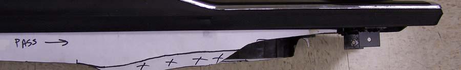
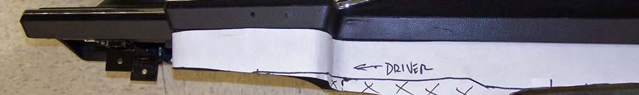
4 Fig 4-1. Tunnel hole cut. 4. Cutout the body metal bend line paper pattern from sheet 2 of the tunnel cutting template. Align it over the flat tunnel body sheet metal BMG and tape it in place. Mark the end points of the bend lines thru the (4) small window cutouts and along the front edge of the body metal. 5. Remove the paper pattern and draw or scribe bend lines between endpoints. 6. Form the new tunnel body metal by bending along the marked bend lines to create an arch in the metal and bend tabs A-A and B-B as shown on template. The body metal will need to be custom fitted to match the contour around the newly cut opening in your tunnel. The final shape of new tunnel body metal should look similar to pictures shown in Figs 4-2 and 4-3 (Pictures are shown with shifter hole cutout added after body metal has been prepared and fitted for final attachment to your tunnel. Step 10a on page 5 will detail how to locate cut hole.) Fig 4-2. Driver side iso view of formed body metal Fig 4-3. Pass side iso view of formed body metal 7. The new body metal must be correctly located in vertical direction to provide required clearance to top surface of T56 Magnum shifter assembly. Temporarily install new crossmember XMG with rear edge of perch area located 31.5 from rear face of block. It is not necessary to bolt crossmember into place for this step. 8. Adjust fit of new body metal over your cut tunnel opening to obtain a vertical distance of 9.25 from top surface of crossmember perch area to bottom surface of the new body metal formed tunnel as shown in Fig 5-1. (Picture is shown with shifter hole cutout added after body metal has been prepared and fitted for final attachment to your tunnel attachment. Step 10a on page 5 will detail how to locate cut hole.) 4


 on driveline centerline and mark tower center location on top surface along")


5 Fig Once the new body metal has been formed and fitted to your tunnel, a trial fit for T56 Magnum clearance should be done before permanently attaching the new tunnel body metal. 10. Temporarily attach bell housing, without clutch components, to the engine. a. From engine RFB, measure 23.5 (if using 5.95 deep QT bell housing) or 24.3 (if using 6.3 deep GM bell housing plus 0.5 adapter plate) or 17.5 from front mounting face of T56 Magnum) on driveline centerline and mark tower center location on top surface along both sides of the tunnel hole cut. b. Attach formed tunnel body metal to floor using pop rivets, screws, or Cleco fasteners. Be sure to maintain vertical height of 9.25 as detailed per Step 8 from page 4. c. Cutout and tape shifter hole cut template TMG on tunnel body metal by locating on driveline centerline with shift tower center locating hole aligned with center location marked on both sides of tunnel hole cut as located by Step 10a. See Fig. 6-1 d. Mark and cut shifter hole opening in tunnel. e. The final shift handle connection joint will be positioned in the same location as the original factory shifter handle to allow handle to fit in factory boot and console opening. 5


6 See Step 10a 33 Fig 6-1. Fig Temporarily install T56 Magnum transmission to bell housing using bolts from Hardware Pack HWG-PACK A T56. For added clearance for offset shifter stub to clear tunnel hole when transmission is being installed, place transmission into 5 th or REV gear. 12. NOTE: DO NOT REMOVE SHIFTER TOWER FROM SHIFTER BASE PLATE to gain clearance for installation. Shift stub seal in shifter base plate could be damaged or not properly fitted on lower stub lever if tower is reinstalled on shifter base plate. 13. Attach isolator mount to transmission using Hardware Pack HWG-PACK H. Using jack, raise rear of engine/transmission as far as possible to allow crossmember to be installed. 14. The new Magnum crossmember is too long to fit under the transmission and be able to rotate mount ends above side frame rails. Install new crossmember with the pre-attached end mount positioned on driver side of car. See Fig 6-3. Rotate opposite end up toward the passenger side frame rail (See Fig 6-4) and install passenger side end mount above the frame rail mounting surface with (2) bolts supplied. Fig Fig

7 15. Position crossmember perch area under isolator and lower transmission to rest on crossmember. Keep transmission secured to jack there is no need to install the crossmember to isolator bolts for this clearance fit check. 16. Verify 1/8-1/4 minimum clearance between T56 Magnum and tunnel. 17. Verify shift tower clearance of 1/4" to passenger side of the shifter hole in tunnel. 18. This would be a good time to take the driveline measurement per the driveline instruction sheet so that the new SST driveshaft can be ordered. See MAA form in the customer info pack. 19. Remove bell housing, crossmember (remove passenger side end mount to clear frame rail), and the transmission in order to gain access to complete final tunnel installation. 20. Attach new tunnel body to car using rivets, screws, or by welding. 21. Attach original front console mounting bracket on driveline centerline top of new tunnel body metal located 33 from the (2) holes in rear console mounting bracket. See Fig Apply body sealer LORD Fuser 803DTM Metal Sealer or equivalent around perimeter joint to prevent water intrusion. Paint exposed sheet metal surfaces for corrosion protection. C. INSTALL NEW EQUIPMENT Before installing, please note that Oldsmobile crankshafts on factory automatic cars were not machined to accept a pilot bearing. The crankshaft will need to be machined or you could purchase an adapter and shorten the input shaft. 1. Clean all mating engine surfaces and dowel pins. Verify dowel pin full diameter exposed length is greater than 3/8 to assure that Quick Time bell housing will be accurately positioned with the Quick Time engine block installed. Reposition or replace with longer dowel pins if necessary. 2. If using Quick Time bell housing, be sure to install engine block plate prior to installing flywheel. Install new flywheel and flywheel bolts torqued to factory spec. Be sure to tighten bolts in alternating pattern sequence. 3. Install new pilot bearing assembly into crankshaft using a socket of similar diameter to the bearing and a rubber mallet. The side with the needle roller bearing grease seal faces the transmission. Gently tap bearing fully into crankshaft until bearing face is flush with crankshaft face. Pilot bearing is designed to be light press fit ( press). Replace or modify pilot bearing if necessary. CHEVROLET PILOT BRG. PONTIAC PILOT BRG. (TRANSMISSION SIDE SHOWN) 7

8 4. Using clutch alignment tool, attach clutch disc and pressure plate to flywheel. Install each bolt only finger tight on the first round, then incrementally tighten each one in an alternating sequence until all are snug. Torque each one in the same sequence to 35 lb.-ft. 5. Lower rear of engine as far as possible (required for new transmission installation). 6. With the bellhousing still removed from the engine, install clutch fork and release bearing in the bellhousing if using mechanical clutch linkage. The tips of the clutch fork and the spring fingers on the rear side of the clutch fork both fit inside the groove on the release bearing. 7. Install bellhousing to engine, while making sure there are no hoses, cables, or wires caught between the bellhousing and engine block. Torque the fasteners to the specification found in your factory service manual or Quick Time instructions. 8. It will be easier to add ATF fluid at this point before completing the final installation of T56 Magnum transmission. See MAA The fill plug is on the left side of the transmission midway up the case. Use pipe sealant - but do not over tighten the tapered pipe plug until head is flush with boss. Be sure to use shipping plug installed into rear seal to prevent fluid loss during installation. NOTE: DO NOT REMOVE SHIFTER TOWER FROM SHIFTER BASE PLATE to add ATF fluid. Shift stub seal in shifter base plate could be damaged or not properly fitted on stub lever if tower is reinstalled on shifter base plate. 9. At this point either install the clutch pedal rod, Z bar mounts, Z bar, retainer springs, and pushrod. If using a SST Hydraulic system (available separately) follow instructions provided, MAG When installing T56 Magnum transmission, use caution when inserting the input shaft into the clutch disc and pilot bearing. Do not allow weight of transmission to rest on assembly until fully engaged (doing so can misalign disc or damage pilot bearing). 11. DO NOT UNDER ANY CIRCUMSTANCES use the transmission-tobellhousing bolts to draw/pull the transmission up to the bellhousing! This could damage the input shaft of the transmission and is not covered by Silver Sport Transmissions Warranty. If the transmission will not slide up to the bellhousing, there is a problem. Stop and call Silver Sport Transmissions for a consultation. NOTE: If the transmission stops approximately 1/2 away from seating fully against the bellhousing, install and finger-tighten bellhousing to transmission bolts. Connect clutch linkage and depress pedal lightly while pushing transmission forward to facilitate alignment of clutch disk to input shaft and pilot bearing. DO NOT force the transmission into engagement damage to the pilot bearing may result. Tighten bellhousing to 12. Once engine the transmission bolts once the is transmission fully seated by is seated hand against the the bellhousing, bellhousing. fasten with bolts provided (HWG-PACK A T56). 8
. 15.")
9 13. Raise up engine/transmission until transmission contacts the top of the tunnel. 14. If not already installed after tunnel clearance check, attach rubber isolator mount to transmission using M x 30 bolts and lock washers (HWG-PACK H). 15. Repeating the same procedure as before for installing crossmember (Section B Step 13), place your crossmember on the frame rails so that perch mounting slots lines up with the new isolator mount holes. Lower transmission fully onto crossmember, and attach to mount with hardware pack HWG-PACK B. Confirm no interference to car body or noise will occur as the driveline moves under load. 16. Crossmember end mount holes should line up to use the next to rear set of holes on frame rail. If not, mark location of new holes required for attaching the crossmember to the frame. Drill holes as needed on each frame rail along the same centerline as the factory holes. 17. Attach the crossmember to the frame using your original hardware. For BOP cars, also reuse the original rubber end mount bracket and hardware. 18. Remove shipping plug, and insert slip yoke fully until touching transmission seal rubber dust boot. Set driveshaft into position at differential and seat u-joints into differential pinion yoke. Make certain all parts are clean and properly assembled. 19. Install straps and torque to factory specs: 17 lb-ft for 1310/1330 U-bolts (excessive torque can distort bearing cap leading to premature failure). Double check your assembly. 20. This would be a good time to double check driveline operating angles to confirm front and rear angles are within recommended values. Adjust as necessary. 21. Install E-brake cables. Adjust tension per factory specs. 22. Reinstall bell housing dust cover/inspection cover and starter. 23. Connect clutch linkage - do not preload release bearing. Adjust linkage as required. 24. Splice backup light harness into original harness. The backup light switch is on the right side of the main case. 25. The reverse lockout solenoid needs to be wired to be energized when shifting into REV. This can be done in one of two ways: a. Wire solenoid pigtail into the brake light circuit so the reverse lockout solenoid is energized when the brakes are applied. The reverse solenoid is at the rear of the transmission near the top of the extension housing. One wire from the reverse lockout solenoid pigtail must be grounded and can be connected to the crossmember. b. Wire solenoid pigtail into the optional ELAP-T56RLO lockout control module. See instructions included with the module kit. 26. Re-install and tighten exhaust. 27. Install new speedo cable per MAA Wrap tape around speedometer cable ends to prevent damage and keep them clean while routing new speedometer cable to transmission. Remove rubber plug from the speedometer cable port on left side (see photo right) and install new speedometer cable with gear, clip and o-ring (HWA-PACK S) into transmission case. Install cable retainer bolt and tighten bolt to 4 lb.-ft. Connect cable to speedometer. NOTE ORIENTATION OF RETAINING CLIP 9


10 29. You are now ready to install shifter patch panel with body seal, and seal panel on the tunnel area. a. Place shifter opening patch panel BMG over T56 Magnum shifter with the opening around the shifter tower. Opening must be centered around tower. Adjust bend of panel if needed to conform to tunnel shape on driver side. b. Using a marking pen, draw outline of the patch panel and mark the (5) 3/16 dia holes plus (2) 1/8 dia holes at front and passenger side around the edge of the shift tower opening for drilling. See Fig c. Remove patch panel and drill (7) 7/64 dia holes for #8 sheet metal attachment screws. Use caution on drill depth for holes adjacent to front and rear of shift tower do not drill into shifter mount plate. d. Apply bead of Permatex Black Silicon Adhesive Sealant #81158 (or equivalent) to top surface of tunnel console within the previously marked outline of patch panel. Press patch panel into place to form tight bond with tunnel. e. Install (5) #8 x 3/8 lg sheet metal screws provided (HWG-PACK C3S) to secure patch panel to tunnel. See Fig Do NOT over tighten screws. (Sheet metal screws are used to allow easy removal for future transmission or clutch service). f. Install shift tower to body seal, TRS , with open flange up. Press lower lip of body seal down into gap between shift tower and patch panel opening. See Fig g. Install seal panel BMG-04003, sandwiching the lip of the body seal between the patch and seal panels, and attach with (4) sheet metal screws. Do NOT overtighten screws. See Fig h. Apply bead of the sealant around perimeter of the shift tower to complete the tunnel sealing system. See Fig Fig Fig


11 Fig Fig Fig Fig

12 30. Install front carpet and seat(s). 31. Before console can be installed, it may be necessary to trim bottom edges to lay on carpet over your modified tunnel. The amount of trim required will vary with each application but should be approx. 1 in X d out areas shown in pictures (see Fig and Fig.11-4 ) of an example paper pattern attached to driver and passenger sides of a 1967 Chevelle console. 32. Install console. 33. Install new 6 speed shift pattern plate. 34. Bolt on upper shift handle with 3/8-24 x 1 bolts and washers provided (HWA-PACK L). Use medium strength threadlock compound. Torque to 25 lb.-ft. Confirm shifter motion through all gears. 35. Reconnect battery negative (-) cable. 36. Install shifter boot and retainer ring, and/or console if equipped. 37. Connect throttle linkage to carburetor. 38. Install distributor cap and breather. 39. Tighten fan shroud if it was loosened earlier. 40. Reconnect the negative (-) battery cable. QUALITY CHECK It is important you confirm your work: 1. All bolts tightened to specifications 2. Full fill of Dexron III oil in transmission. Do not over tighten plug until head is flush with boss. This is tapered pipe plug. 3. Driveshaft fully assembled at both ends. Minimum 1/4 clearance around moving parts. 4. Shifter operates smoothly through all gears. 5. No vibration at idle speed, upper RPM or highway speed. Silver Sport Transmissions is dedicated to your satisfaction and enjoyment of this product. Please send us pictures of your car along with a testimonial of how you rate this product. We will be posting many customer feedback letters and pictures on our web-site and catalogs. 12
13 D. FINAL INSPECTION AND START UP PROCEDURE Start engine and let idle for 2 minutes. Slowly rev engine in neutral and listen for odd noises. Feel for vibration in driveline. With clutch disengaged, shift through all gears. Do not shift into reverse at RPM higher than idle. Test drive at low speeds and low RPMs. Gradually test higher RPMs, then higher speeds. If you experience a vibration at cruising speeds, it may be necessary to adjust the rear end angle to achieve the correct driveshaft angle. Please refer to factory manuals for measurement and adjustment methods. If you experience a vibration at zero speed, as you rev up engine with clutch released, a faulty flywheel/clutch plate balance may exist. If vibration occurs when depressing the clutch pedal only a release bearing may be faulty. Reverse is synchronized and uses a reverse lockout solenoid wired into the brake light wiring to ensure the vehicle is stopped prior to engaging reverse. Drive easy for 500 miles break-in period. CONTACT INFORMATION Change oil at 30,000 miles. Spare parts are available from SST SILVER SPORT TRANSMISSIONS or an authorized TREMEC distributor STOCK CREEK BOULEVARD ROCKFORD, TENNESSEE E. SPECIFICATIONS Do not exceed input torque 700 lb-ft in 4 th gear Phone: (865) Toll Free: (888) Fax: (865) Gear ratios: CLOSE WIDE 1 st st nd nd rd rd th th th th th th SILVER SPORT TRANSMISSIONS IS DEDICATED TO YOUR SATISFACTION AND ENJOYMENT OF THIS PRODUCT. PLEASE SEND US PICTURES OF YOUR CAR ALONG WITH A TESTIMONIAL OF HOW YOU RATE THIS PRODUCT. WE WILL BE POSTING MANY CUSTOMER FEEDBACK LETTERS AND PICTURES ON OUR WEBSITE AND BROCHURES. ENJOY YOUR SILVER SPORT TRANSMISSION SYSTEM! 13
CORVETTE (Factory Manual Conversion)
") 1968 1979 CORVETTE (Factory Manual Conversion) T56 MAGNUM 6-SPEED INSTALLATION MANUAL FOLLOW FACTORY SERVICE MANUAL (FSM) RECOMMENDED SAFETY PRECAUTIONS. TRANSMISSION REMOVAL AND INSTALLATION IS A LABOR
1968 1979 CORVETTE (Factory Manual Conversion) T56 MAGNUM 6-SPEED INSTALLATION MANUAL FOLLOW FACTORY SERVICE MANUAL (FSM) RECOMMENDED SAFETY PRECAUTIONS. TRANSMISSION REMOVAL AND INSTALLATION IS A LABOR
CAMARO/FIREBIRD
 CAMARO/FIREBIRD 1967-1969 TKO 5-SPEED MANUAL TO MANUAL TRANSMISSION CONVERSION INSTALLATION MANUAL FOLLOW FACTORY SERVICE MANUAL (FSM) RECOMMENDED SAFETY PRECAUTIONS. TRANSMISSION REMOVAL AND INSTALLATION
GM B-BODY IMPALA
 GM B-BODY IMPALA 1965-1970 TKO 5-SPEED MANUAL TO MANUAL TRANSMISSION CONVERSION INSTALLATION MANUAL FOLLOW FACTORY SERVICE MANUAL (FSM) RECOMMENDED SAFETY PRECAUTIONS. TRANSMISSION REMOVAL AND INSTALLATION
CHEVROLET NOVA
 CHEVROLET NOVA 1962-1967 TKO 5-SPEED MANUAL TO MANUAL TRANSMISSION CONVERSION INSTALLATION MANUAL FOLLOW FACTORY SERVICE MANUAL (FSM) RECOMMENDED SAFETY PRECAUTIONS. TRANSMISSION REMOVAL AND INSTALLATION
CAMARO/FIREBIRD
 CAMARO/FIREBIRD 1970-1981 TKO 5-SPEED MANUAL TO MANUAL TRANSMISSION CONVERSION INSTALLATION MANUAL FOLLOW FACTORY SERVICE MANUAL (FSM) RECOMMENDED SAFETY PRECAUTIONS. TRANSMISSION REMOVAL AND INSTALLATION
CHEVELLE / CUTLASS
 CHEVELLE 1968-1972 442 / CUTLASS 1970-1972 TKO 5-SPEED MANUAL TO MANUAL TRANSMISSION CONVERSION INSTALLATION MANUAL FOLLOW FACTORY SERVICE MANUAL (FSM) RECOMMENDED SAFETY PRECAUTIONS. TRANSMISSION REMOVAL
TKO 5-SPEED MANUAL TO MANUAL
 GENERAL INSTALLATION (MANUAL TRANS) TKO 5-SPEED MANUAL TO MANUAL TRANSMISSION CONVERSION INSTALLATION MANUAL FOLLOW FACTORY SERVICE MANUAL (FSM) RECOMMENDED SAFETY PRECAUTIONS. TRANSMISSION REMOVAL AND
MOPAR B-BODY
 MOPAR B-BODY 1962-1970 TKO 5-SPEED MANUAL TO MANUAL TRANSMISSION CONVERSION INSTALLATION MANUAL FOLLOW FACTORY SERVICE MANUAL (FSM) RECOMMENDED SAFETY PRECAUTIONS. TRANSMISSION REMOVAL AND INSTALLATION
C2 CORVETTE (Factory Manual Conversion)
") 1963 1967 C2 CORVETTE (Factory Manual Conversion) T56 MAGNUM 6-SPEED INSTALLATION MANUAL FOLLOW FACTORY SERVICE MANUAL (FSM) RECOMMENDED SAFETY PRECAUTIONS. TRANSMISSION REMOVAL AND INSTALLATION IS A LABOR
1963 1967 C2 CORVETTE (Factory Manual Conversion) T56 MAGNUM 6-SPEED INSTALLATION MANUAL FOLLOW FACTORY SERVICE MANUAL (FSM) RECOMMENDED SAFETY PRECAUTIONS. TRANSMISSION REMOVAL AND INSTALLATION IS A LABOR
CORVETTE TKO 5-SPEED MANUAL TO MANUAL TRANSMISSION CONVERSION INSTALLATION MANUAL
 CORVETTE 1968 1982 TKO 5-SPEED MANUAL TO MANUAL TRANSMISSION CONVERSION INSTALLATION MANUAL FOLLOW FACTORY SERVICE MANUAL (FSM) RECOMMENDED SAFETY PRECAUTIONS. TRANSMISSION REMOVAL AND INSTALLATION IS
CORVETTE TKO 5-SPEED MANUAL TO MANUAL TRANSMISSION CONVERSION INSTALLATION MANUAL
 CORVETTE 1963-1967 TKO 5-SPEED MANUAL TO MANUAL TRANSMISSION CONVERSION INSTALLATION MANUAL FOLLOW FACTORY SERVICE MANUAL (FSM) RECOMMENDED SAFETY PRECAUTIONS. TRANSMISSION REMOVAL AND INSTALLATION IS
MOPAR E-BODY MOPAR B-BODY
 MOPAR E-BODY 1970-1974 MOPAR B-BODY 1971-1974 TKO 5-SPEED MANUAL TO MANUAL TRANSMISSION CONVERSION INSTALLATION MANUAL MAM-01001 MOPAR E-BODY 1970-1974, B-BODY 1971-1974 TKO Installation Manual, Rev A
CORVETTE TKO 5-SPEED MANUAL TO MANUAL TRANSMISSION CONVERSION INSTALLATION MANUAL
 CORVETTE 1984 1988 TKO 5-SPEED MANUAL TO MANUAL TRANSMISSION CONVERSION INSTALLATION MANUAL FOLLOW FACTORY SERVICE MANUAL (FSM) RECOMMENDED SAFETY PRECAUTIONS. TRANSMISSION REMOVAL AND INSTALLATION IS
GM C10 TRUCK HYDRAULIC MOUNT INSTALLATION INSTRUCTIONS
 GM C10 TRUCK HYDRAULIC MOUNT INSTALLATION INSTRUCTIONS The material herein is the intellectual property of Silver Sport Transmissions ( SST ) and is to be used by SST customers or their authorized installers
FORD F-100 TRUCK
 FTE Style Bearing RAM Style Bearing FORD F-100 TRUCK 1973-79 HYDRAULIC MOUNT INSTALLATION INSTRUCTIONS The material herein is the intellectual property of Silver Sport Transmissions ( SST ) and is to be
CAMARO / FIREBIRD 1970½
 CAMARO / FIREBIRD 1970½ - 1981 4-SPEED ELECTRONICALLY CONTROLLED AUTOMATIC TRANSMISSION INSTALLATION MANUAL MAG-02006 A41 F2 CAMARO_FIREBIRD Installatin Manual_revD 3/23/17 FOLLOW FACTORY SERVICE MANUAL
CAMARO / FIREBIRD
 CAMARO / FIREBIRD 1967-1969 4-SPEED ELECTRONICALLY CONTROLLED AUTOMATIC TRANSMISSION INSTALLATION MANUAL MAG-02001 A41 F1 Camar/Firebird Installatin Manual_revF 10/04/16 FOLLOW FACTORY SERVICE MANUAL (FSM)
MOPAR A-Body B-Body E-Body
 MOPAR 67-76 A-Bdy 66-74 B-Bdy 70-74 E-Bdy 4-SPEED ELECTRONICALLY CONTROLLED AUTOMATIC TRANSMISSION INSTALLATION MANUAL MAM-02001 A41 MOPAR A, B, & E-Bdy Installatin Manual_revP 09/25/14 FOLLOW FACTORY
TRANSMISSION INSTALLATION CONTENTS
 A REGAL-BELOIT Company TRANSMISSION INSTALLATION CONTENTS RICHMOND 6-SPEED TRANS AM, CAMARO, CHEVELLE, GTO, CUTLASS, WITH T-10/MUNCIE............2 RICHMOND 6-SPEED 1963 TO 1982 CORVETTE WITH T-10 OR MUNCIE..............................3
HYDRAULIC KIT INSTRUCTIONS FOR GM - MUNCIE
 HYDRAULIC KIT INSTRUCTIONS FOR GM - MUNCIE BEFORE INSTALLING TRANSMISSION IN CAR, YOU MUST CHECK THE HYDRAULIC BEARING CUSHION MEASUREMENT!!! SEE PAGE 7 OF INSTALLATION MANUAL FOR INSTRUCTIONS ON MEASURING
Installation Instructions COMPETITION/PLUS SHIFTER Ford Mustang MT82 6-Speed Manual Transmission Catalog#
 Installation Instructions COMPETITION/PLUS SHIFTER 2015-2017 Ford Mustang MT82 6-Speed Manual Transmission Catalog# 3916037 Rev. 00 WORK SAFELY! For maximum safety, perform this installation on a clean,
Powerglide Automatic Floor Mount Shifter Installation Instructions
 Powerglide Automatic Mount Installation Instructions Building American Quality With A Lifetime Warranty! TOLL FREE 1-877-469-7440 (865) 966-2269 FAX (865) 671-1999 tech@lokar.com www.lokar.com Powerglide
GM Floor Mount Automatic Transmission Shifter Installation Instructions
 GM Mount Automatic Transmission Shifter Installation Instructions Building American Quality With A Lifetime Warranty! TOLL FREE 1-877-469-7440 tech@lokar.com www.lokar.com GM Mount Automatic Transmission
Chrysler 727, 904, 518 Floor Mount Automatic Transmission Shifter Installation Instructions
 Chrysler 727, 904, 518 Mount Automatic Transmission Shifter Installation Instructions Building American Quality With A Lifetime Warranty! TOLL FREE 1-877-469-7440 tech@lokar.com www.lokar.com Release Button
Borg & Beck Clutch Information
 Borg & Beck Clutch Information After the clutch is bolted to the flywheel, under no circumstance should the release lever, or the release lever plate if equipped, be pulled away from the flywheel against
Ford C4 and C6 Floor Mount Automatic Transmission Shifter Installation Instructions
 Ford C4 and C6 Mount Automatic Transmission Shifter Installation Instructions Building American Quality With A Lifetime Warranty! TOLL FREE 1-877-469-7440 tech@lokar.com www.lokar.com Ford C4 and C6 Mount
LAKEWOOD/QUICKTIME SAFETY BELLHOUSING INSTALLATION INSTRUCTIONS
 LAKEWOOD/QUICKTIME SAFETY BELLHOUSING INSTALLATION INSTRUCTIONS Congratulations on your purchase of the finest quality steel bellhousing available today. 100% Manufactured in the USA! Please understand
SECTION 5B MANUAL TRANSMISSION TABLE OF CONTENTS
 SECTION 5B MANUAL TRANSMISSION TABLE OF CONTENTS General Description and Operation... 5B-2 Shift Lever... 5B-2 Transmission Assembly... 5B-2 Specifications... 5B-3 Diagnostic Information and Procedures...
 www.clubsuprafrance.com CLUTCH 1996 Toyota Supra 1995-96 Clutch Supra DESCRIPTION The single, dry-type disc clutch uses a hydraulicallyoperated master cylinder with a clutch release cylinder mounted on
Technical Support (707)
") Installation Instructions CONSOLE MEGASHIFTER Fits: 1982-1992 Camaro & Firebird w/automatic Transmission *except 1988-1992 Firebird Formula Model Catalog # 80692 WORK SAFELY! For maximum safety, perform
Installation Instructions CONSOLE MEGASHIFTER Fits: 1982-1992 Camaro & Firebird w/automatic Transmission *except 1988-1992 Firebird Formula Model Catalog # 80692 WORK SAFELY! For maximum safety, perform
1 M-3000-H4 F150 4X4 Lowering Kit
 READ INSTRUCTIONS COMPLETELY THROUGH BEFORE STARTING. IT IS RECOMMENDED THAT INSTALLATION BE DONE BY A QUALIFIED MECHANIC. REPLACE ALL STOCK PARTS THAT ARE DAMAGED OR WORN. ALWAYS WEAR EYE PROTECTION.
ADVANCE ADAPTERS INC. P/N: JEEP TJ & (XJ 84-01) ATLAS 4 SPEED CABLE SHIFTER units built after 5/1/12
 ATLAS 4 SPEED CABLE SHIFTER units built after 5/1/12") Paso Robles, CA 93447 PAGE 1 OF 9 Telephone: (800) 350-2223 Fax: (805) 238-4201 Page Rev. Date: 05-12-15 KIT CONSISTS OF: No. Qty Part No. Description 1 1 302051 BASE- TWIN STICK MOUNT 2 1 302080 STUD
Paso Robles, CA 93447 PAGE 1 OF 9 Telephone: (800) 350-2223 Fax: (805) 238-4201 Page Rev. Date: 05-12-15 KIT CONSISTS OF: No. Qty Part No. Description 1 1 302051 BASE- TWIN STICK MOUNT 2 1 302080 STUD
63162K 2015 Chevrolet Colorado 4WD Leveling Kit w/ 1 Rear Lift Kit
 PRO COMP SUSPENSION 63162K 2015 Chevrolet Colorado 4WD Leveling Kit w/ 1 Rear Lift Kit This document contains very important information that includes warranty information and instructions for resolving
CLUTCH 6-1 CLUTCH TABLE OF CONTENTS
 PL CLUTCH 6-1 CLUTCH TABLE OF CONTENTS page DESCRIPTION AND OPERATION MODULAR CLUTCH ASSEMBLY....1 CLUTCH CABLE...1 CLUTCH INTERLOCK/UPSTOP SWITCH....1 DIAGNOSIS AND TESTING CLUTCH SYSTEM DIAGNOSIS...2
Installation Instructions INDY SHIFTER Fits: Mustang Fastback & Convertible with MT-82 Transmission Catalog #
 Installation Instructions INDY SHIFTER Fits: 2015-2018 Mustang Fastback & Convertible with MT-82 Transmission Catalog # 3916036 Watch our installation video on YouTube WORK SAFELY! For maximum safety,
Ford AOD-4R70W-AODE Cable Operated Shifter Installation Instructions
 Ford AOD-4R70W-AODE Cable Operated Shifter Installation Instructions Building American Quality With A Lifetime Warranty! TOLL FREE 1-877-469-7440 tech@lokar.com www.lokar.com Ford AOD-4R70W-AODE Cable
JEEP TJ & (XJ 84-01) ATLAS 2 SP.
 ATLAS 2 SP.") KIT CONSISTS OF: No. Qty Part No. Description 4320 Aerotech Center Way, Page 1 of 9 1 1 302051-RLE BASE- TWIN STICK MOUNT 42RLE 2 1 302080 STUD BOLT 1/2"-13 X 7 (XJ) 3 1 303120 SERRATED LOCK NUT 1/2" X
KIT CONSISTS OF: No. Qty Part No. Description 4320 Aerotech Center Way, Page 1 of 9 1 1 302051-RLE BASE- TWIN STICK MOUNT 42RLE 2 1 302080 STUD BOLT 1/2"-13 X 7 (XJ) 3 1 303120 SERRATED LOCK NUT 1/2" X
Photo 1. Shift pattern gate plate
 Installation Instructions MAGNUM GRIP STREET BANDIT SHIFTER Fits: GM, Chrysler, and Ford Automatic Transmissions See Application Guide for Specific Vehicles Catalog # 81050 WORK SAFELY! For maximum safety,
DODGE DAKOTA 3 BODY LIFT INSTALLATION INSTRUCTIONS KIT # 60153
 DODGE DAKOTA 3 BODY LIFT INSTALLATION INSTRUCTIONS 2003-04 KIT # 60153 Installation of a Performance Automotive Group body lift kit will change the vehicle s center of gravity and handling characteristics
700-R4, 4L60, and 4L60E Automatic Trans Mount Shifter Installation Instructions
 700-R4, 4L60, and 4L60E Automatic Trans Mount Installation Instructions Building American Quality With A Lifetime Warranty! TOLL FREE 1-877-469-7440 tech@lokar.com www.lokar.com 700-R4, 4L60, and 4L60E
Short-throw Shifter Installation Guide
 Short-throw Shifter Installation Guide Removal Procedure 1) Remove the shift control knob. A. Lift up on the rear portion of the shift control closeout boot retaining ring and detach the retaining ring
Transmission Overhaul Procedures-Bench Service
 How to Assemble the Lower Reverse Idler Gear Assembly Special Instructions In 1996 Eaton changed the reverse idler system design. In the nut design, the reverse idler bearing was lubricated through a hole
NV3550 TO FORD BRONCO
 NV3550 TO 1966-77 FORD BRONCO KIT CONSISTS OF: No. 1. 2. 3. 4. 5. Qty 1 1 Kit 1 Kit 1 Kit 1 Kit Part No. 26-3550 50-9920 712544 716000 716099 Description NV3550 TRANSMISSION TRANSFER CASE ADAPTER & TC
B&M / INTRODUCTION
 INSTALLATION INSTRUCTIONS FOR B&M AUTOMATIC TRANSMISSIONS REPLACING GM TH350, TH400, and TH700R4 / 4L60 (not including 4L60E / electronic shift models) B&M part numbers: 102002-103005 - 107101-107104 107105-107106
ch2200 ch2300 mt3 osprey pro-trim single s twin s sl-3 INSTALLATION INSTRUCTIONS AND OWNERS MANUAL
 MEMBER INSTALLATION INSTRUCTIONS AND OWNERS MANUAL Part # IS-CH2200/2300, Rev, 08/203 www.seastarsolutions.com ch2200 ch2300 mt3 osprey pro-trim single s twin s sl-3 MANUFACTURED BY MARINE ACQUISITION
Chrysler 45RFE Tailmount Automatic Transmission Shifter Installation Instructions
 Chrysler 45RFE Tailmount Automatic Transmission Installation Instructions Building American Quality With A Lifetime Warranty! TOLL FREE 1-877-469-7440 tech@lokar.com www.lokar.com Chrysler 45RFE Tailmount
Audi B7 A4 2.oT Lightweight Flywheel. Installation Tutorial ES
 Audi B7 A4 2.oT Lightweight Flywheel Installation Tutorial ES2739501 Project Preparation Safety Leave the car in neutral. Park the vehicle in a safe, well lit, level area. Open the hood and place protective
JEEP TJ & (XJ 84-01) ATLAS 2 SPEED CABLE SHIFTER units built before 4/30/12
 ATLAS 2 SPEED CABLE SHIFTER units built before 4/30/12") KIT CONSISTS OF: No. Qty Part No. Description 4320 Aerotech Center Way, Page 1 of 6 1 1 302051-RLE BASE- TWIN STICK MOUNT 42RLE 2 1 302080 STUD BOLT 1/2"-13 X 7 (XJ) 3 1 303120 SERRATED LOCK NUT 1/2"-
KIT CONSISTS OF: No. Qty Part No. Description 4320 Aerotech Center Way, Page 1 of 6 1 1 302051-RLE BASE- TWIN STICK MOUNT 42RLE 2 1 302080 STUD BOLT 1/2"-13 X 7 (XJ) 3 1 303120 SERRATED LOCK NUT 1/2"-
HURST COMP/PLUS SHIFTER 2015 Ford Mustang (Getrag MT82 six-speed manual transmission) Catalog # by Hurst Performance
 Catalog # by Hurst Performance") FORM 159 0205 07/15 HURST COMP/PLUS SHIFTER 2015 Ford Mustang (Getrag MT82 six-speed manual transmission) Catalog #391 0205 2015 by Hurst Performance Thank you for purchasing the Hurst Comp/Plus Shifter.
FORM 159 0205 07/15 HURST COMP/PLUS SHIFTER 2015 Ford Mustang (Getrag MT82 six-speed manual transmission) Catalog #391 0205 2015 by Hurst Performance Thank you for purchasing the Hurst Comp/Plus Shifter.
SPECIAL TOOLS Dodge Pickup 5.9L Eng R3500. Fig 1: Identifying Remover C-3985-B (Special Tool) 9/6/13 Printer Friendly View
 9/6/13 Printer Friendly View") Procedures 2003 Dodge Pickup 5.9L Eng R3500 manual transmission SPECIAL TOOLS Fig 1: Identifying Remover C-3985-B (Special Tool) www2.prodemand.com/print/index?content=tabs&module=true&tab=true&terms=true&ymms=false&classname=
Procedures 2003 Dodge Pickup 5.9L Eng R3500 manual transmission SPECIAL TOOLS Fig 1: Identifying Remover C-3985-B (Special Tool) www2.prodemand.com/print/index?content=tabs&module=true&tab=true&terms=true&ymms=false&classname=
AEV30213AH Last Updated: 04/28/17. jk wrangler dualsport sc suspension INSTALLATION GUIDE
 AEV30213AH Last Updated: 04/28/17 jk wrangler 3.5 4.5 dualsport sc suspension INSTALLATION GUIDE PLEASE READ BEFORE YOU START TO GUARANTEE A QUALITY INSTALLATION, WE RECOMMEND READING THESE INSTRUCTIONS
PRODUCT USE INFORMATION
 9RC61000 Jeep YJ Body Lift Thank you for choosing Rough Country for all your suspension needs. This body lift fits both manual and Automatic equipped vehicles!!! Refer to last page of this Instruction
Ford AOD-4R70W-AODE Cable Operated Shifter Installation Instructions
 Ford AOD-4R70W-AODE Cable Operated Shifter Installation Instructions Building American Quality With A Lifetime Warranty! TOLL FREE 1-877-469-7440 tech@lokar.com www.lokar.com Ford AOD-4R70W-AODE Cable
2-row and All-row systems included.
 Ag Leader Technology Cotton Picker Installation Installation Instructions for John Deere cotton picker models: 2-row and All-row systems included. IMPORTANT: Ensure the model numbers shown above correspond
INSTALLATION INSTRUCTIONS 97 FORD EXPEDITION
 INSTALLATION INSTRUCTIONS 97 FORD EXPEDITION 1. Read the instructions completely and carefully before you begin. Check the kit for proper contents (refer to the part s list and the picture diagrams). Before
UNIVERSAL FLOOR SHIFT CONVERSION KIT
 UNIVERSAL FLOOR SHIFT CONVERSION #7668 These instructions apply to the following MR. GASKET products: 7668 - Universal Floor Shift Conversion Kit, Fits Most Rear-Wheel Drive Car Applications With Automatic
Installation Instructions. QuickSilver Shifter. Fits: GM, Ford, Chrysler Transmissions See Application Guide for Specific Applications Part # 80683
 Installation Instructions QuickSilver Shifter Fits: GM, Ford, Chrysler Transmissions See Application Guide for Specific Applications Part # 80683 WORK SAFELY! For maximum safety, perform this installation
JEEP TJ & (XJ 84-01) ATLAS 2 SPEED CABLE SHIFTER units built before 4/30/12
 ATLAS 2 SPEED CABLE SHIFTER units built before 4/30/12") Paso Robles, CA 93447 PAGE 1 OF 6 Telephone: (800) 350-2223 Fax: (805) 238-4201 Page Rev. Date: 05-12-15 KIT CONSISTS OF: No. Qty Part No. Description 1 1 302051-RLE BASE- TWIN STICK MOUNT 42RLE 2 1 302075
Paso Robles, CA 93447 PAGE 1 OF 6 Telephone: (800) 350-2223 Fax: (805) 238-4201 Page Rev. Date: 05-12-15 KIT CONSISTS OF: No. Qty Part No. Description 1 1 302051-RLE BASE- TWIN STICK MOUNT 42RLE 2 1 302075
97-06 JEEP TJ REPL BODY BUSHING / 1 BODY LIFT KIT
 9RC60700 97-06 JEEP TJ REPL BODY BUSHING / BODY LIFT KIT Congratulations on your purchase of a new Rough Country Body Bushing / Body Lift Combo. We are committed to providing you with the best product
SECTION 7B3 - MANUAL TRANSMISSION - GEN III V8 ENGINE
 SECTION 7B3 - MANUAL TRANSMISSION - GEN III V8 ENGINE CAUTION: This vehicle will be equipped with a Supplemental Restraint System (SRS). An SRS will consist of either seat belt pre-tensioners and a driver's
REMOVAL & INSTALLATION
 REMOVAL & INSTALLATION NOTE: For reassembly reference, label all electrical connectors, vacuum hoses and fuel lines before removal. Also place mating marks on engine hood and other major assemblies before
Rostselmash Torum 740
 Note: Indented items indicate parts included in an assembly listed above Quantity by Model Part Name/Description Part Number 740 Combine Kit Torum 740 4100762 1 Threaded Arm Assembly 2000311-2 1 Header
MM Rear Coil-Over Kit - Bilstein Shocks (MMCO-3)
") 3430 Sacramento Dr., Unit D San Luis Obispo, CA 93401 Telephone: 805/544-8748 Fax: 805/544-8645 www.maximummotorsports.com MM Rear Coil-Over Kit - Bilstein Shocks (MMCO-3) Read all instructions before
3430 Sacramento Dr., Unit D San Luis Obispo, CA 93401 Telephone: 805/544-8748 Fax: 805/544-8645 www.maximummotorsports.com MM Rear Coil-Over Kit - Bilstein Shocks (MMCO-3) Read all instructions before
RMK HANDLEBAR KIT P/N ; ; APPLICATION BEFORE YOU BEGIN KIT CONTENTS. Verify accessory fitment at Polaris.com.
 RMK HANDLEBAR KIT P/N 2883835; 2883836; 2883837 APPLICATION Verify accessory fitment at Polaris.com. BEFORE YOU BEGIN Read these instructions and check to be sure all parts and tools are accounted for.
DODGE DAKOTA 3 KIT INSTALLATION INSTRUCTIONS KIT# 60043
 DODGE DAKOTA 3 KIT INSTALLATION INSTRUCTIONS 2000-2002 KIT# 60043 Installation of a Performance Automotive Group body lift kit will change the vehicle s center of gravity and handling characteristics both
TJ 231/241 CABLE SHIFTER
 KIT CONSISTS OF: # Qty Part No. Description P.O. Box 247, 4320 Aerotech Center Way PAGE 1 OF 10 Page Rev. Date: 08-29-16 1 1 300474 WASHER-RUBBER YOKE SEAL 32 SPLINE 2 1 300476 NUT- 7/8"-20 FLANGE LOCKNUT
2001 Chevrolet CORVETTE
 riveline Support Assembly Replacement (Automatic Transmission) 1 of 21 10/24/2012 8:58 PM 2001 Chevrolet CORVETTE Submodel: Engine Type: V8 Liters: 5.7 Fuel Delivery: FI Fuel: GAS Driveline Support Assembly
MANUAL TRANSMISSION MUA 5C (4X2, 4X4) AND TREMEC T5R(4X2)
 AND TREMEC T5R(4X2)") MANUAL TRANSMISSION 7B 1 RODEO TRANSMISSION MANUAL TRANSMISSION MUA 5C (4X2, 4X4) AND TREMEC T5R(4X2) CONTENTS Service Precaution...................... 7B 2 General Description..................... 7B
MANUAL TRANSMISSION 7B 1 RODEO TRANSMISSION MANUAL TRANSMISSION MUA 5C (4X2, 4X4) AND TREMEC T5R(4X2) CONTENTS Service Precaution...................... 7B 2 General Description..................... 7B
Installation Instructions Street Bandit Shifter
 Installation Instructions Street Bandit Shifter Part Number 80797 (see www.bmracing.com for the latest technical product information) 2006, 2000 by B&M Racing and Performance Products The B&M Street Bandit
Z-Gate Universal Shifter
 Installation Instructions Z-Gate Universal Shifter Fits: GM, Ford, Lincoln and Chrysler Transmissions See Application Guide for Specific Applications Part #80681 Rev 06/01/2018 WORK SAFELY! For maximum
WJ AUTO TRANS. ATLAS SHIFTER
 KIT CONSISTS OF: No. Qty Part No. Description 4320 Aerotech Center Way, Page 1 of 8 1 1 302051 BASE- ATLAS TWIN STICK MOUNT 2 1 302080 STUD BOLT 1/2-13 X 7 B7 3 1 303120 Serrated-Flange Hex Locknut 1/2-13
M H F150 4X4 Rear Lowering Kit
 READ INSTRUCTIONS COMPLETELY THROUGH BEFORE STARTING. IT IS RECOMMENDED THAT INSTALLATION BE DONE BY A QUALIFIED MECHANIC. REPLACE ALL STOCK PARTS THAT ARE DAMAGED OR WORN. ALWAYS WEAR EYE PROTECTION.
Installation Instructions
 Powerglide Automatic Trans Mount Installation Instructions Building American Quality With A Lifetime Warranty! TOLL FREE 1-877-469-7440 (865) 966-2269 FAX (865) 671-1999 tech@lokar.com www.lokar.com Powerglide
97-06 Jeep TJ Wrangler 2. 5 " & 4 " S u s p e n s i o n L i f t Installation Instructions
 97-06 Jeep TJ Wrangler 2. 5 " & 4 " S u s p e n s i o n L i f t Installation Instructions Safety Glasses Metric / Standard Wrenches & Sockets Drill / Assorted Drill Bits Floor Jack Jack Stands Measuring
Installation Instructions QUICKSILVER SHIFTER Fits: Chevrolet Camaro Pontiac Firebird Catalog # 80688
 Installation Instructions QUICKSILVER SHIFTER Fits: 1973-1981 Chevrolet Camaro 1970-1981 Pontiac Firebird Catalog # 80688 WORK SAFELY! For maximum safety, perform this installation on a clean, level surface
1989 Jeep Cherokee. STEERING COLUMN' '1989 STEERING Jeep Steering Columns STEERING COLUMN STEERING Jeep Steering Columns
 STEERING COLUMN 1989 STEERING Jeep Steering Columns DESCRIPTION All models use collapsible steering columns. All columns have integral ignition switch and locking device. Optional tilt wheel is available
2004 DRIVELINE/AXLE. Rear Drive Axle - Corvette. Fastener Tightening Specifications Specification Application
 2004 DRIVELINE/AXLE Rear Drive Axle - Corvette SPECIFICATIONS FASTENER TIGHTENING SPECIFICATIONS Fastener Tightening Specifications Specification Application Metric English Differential Case Bolts 55 N.m
This information covers the proper procedure for replacing the Volvo D16F engine in a VT or VNL chassis.
 Volvo Trucks North America Greensboro, NC USA Engine, Replacement DService Bulletin Trucks Date Group No. Page 10.2007 210 139 1(47) Engine, Replacement Volvo D16F VNL, VT W2005773 This information covers
WRANGLER TJ INSTALLATION INSTRUCTIONS
 WRANGLER TJ INSTALLATION INSTRUCTIONS 1997-02 Models Kit# TJ251K/TJ401K 2003-06 Models Kit# TJ253K/TJ403K Before beginning the installation, read these instructions and the enclosed driver s WARNING NOTICE
4L80E Automatic Trans Mount Shifter Installation Instructions
 4L80E Automatic Trans Mount Installation Instructions Building American Quality With A Lifetime Warranty! TOLL FREE 1-877-469-7440 tech@lokar.com www.lokar.com 4L80E Automatic Trans Mount Installation
Installation Instructions QUICKSILVER CONSOLE SHIFTER Fits: Chevelle / El Camino
 WORK SAFELY! For maximum safety, perform this installation on a clean, level surface and with the engine turned off. Place blocks or wedges in front of and behind both rear wheels to prevent movement in
AEV30213AF Last Updated: 05/24/18. jk wrangler dualsport sc suspension right hand drive INSTALLATION GUIDE
 AEV30213AF Last Updated: 05/24/18 jk wrangler 3.5 4.5 dualsport sc suspension right hand drive INSTALLATION GUIDE PLEASE READ BEFORE YOU START TO GUARANTEE A QUALITY INSTALLATION, WE RECOMMEND READING
'99-03 CHEVROLET/GMC IFS 4WD 6" SUSPENSION SYSTEM P/N INSTALLATION INSTRUCTIONS
 1/16/04 '99-03 CHEVROLET/GMC IFS 4WD 6" SUSPENSION SYSTEM P/N. 10-41099 INSTALLATION INSTRUCTIONS NOTE: Each Lift Kit and options to Lift Kits are packaged separately. Therefore, installation procedures
ADVANCE ADAPTERS INC. P/N: TJ 231/241 CABLE SHIFTER
 Paso Robles, CA 93447 PAGE 1 of 10 Telephone: (800) 350-2223 Fax: (805) 238-4201 Page Rev. Date: 09-25-15 KIT CONSISTS OF: # Qty Part No. Description 1 1 300474 WASHER-RUBBER YOKE SEAL 32 SPLINE 2 1 300476
Installation Manual TWM Performance Short Shifter Cobalt SS/SC, SS/TC, HHR SS, Ion Redline and Saab 9-3
 Page 1 Installation Manual TWM Performance Short Shifter Cobalt SS/SC, SS/TC, HHR SS, Ion Redline and Saab 9-3 Please Note: It is preferable to park on a flat surface, as you will have to engage and disengage
97-02 JEEP TJ BODY LIFT KIT INSTRUCTIONS
 92RC60500 97-02 JEEP TJ BODY LIFT KIT INSTRUCTIONS Congratulations on your purchase of a new Rough Country 2 /3 Body Lift. We are committed to providing you with the best product available for the best
TH400 Automatic Trans Mount Shifter Installation Instructions
 TH400 Automatic Trans Mount Installation Instructions Building American Quality With A Lifetime Warranty! TOLL FREE 1-877-469-7440 tech@lokar.com www.lokar.com TH400 Automatic Trans Mount Installation
I. Before starting installation
 5. Park the vehicle on a clean, dry, flat, level surface and block the tires so the vehicle cannot roll in either direction. A. Disconnect battery cables 1. Disconnect the negative cable first, then the
Ford AOD, 4R70W, and AODE Automatic Trans Mount Shifter Installation Instructions
 Ford AOD, 4R70W, and AODE Automatic Trans Mount Installation Instructions Building American Quality With A Lifetime Warranty! TOLL FREE 1-877-469-7440 tech@lokar.com www.lokar.com Ford AOD, 4R70W, and
Suspension System RS6582B
 Suspension System RS6582B Tahoe/Yukon READ ALL INSTRUCTIONS THOROUGHLY FROM START TO FINISH BEFORE BEGINNING INSTALLATION IMPORTANT NOTES! WARNING: This suspension system will enhance the off-road performance
Self-Adjust Clutch Installation Guide
 Self-Adjust Clutch Installation Guide 0 STOP! READ CAREFULLY BEFORE INSTALLING CLUTCH This clutch must be installed by a qualified installer. Improper installation or failure to replace or resurface the
Ford C6 Automatic Trans Mount Shifter Installation Instructions
 Ford C6 Automatic Trans Mount Installation Instructions Building American Quality With A Lifetime Warranty! TOLL FREE 1-877-469-7440 tech@lokar.com www.lokar.com Ford C6 Automatic Trans Mount Installation
1983 BMW 320i. 1.8L 4-CYL 1983 Engines - 1.8L 4-Cylinder Engines - 1.8L 4-Cylinder
 ENGINE IDENTIFICATION 1.8L 4-CYL 1983 Engines - 1.8L 4-Cylinder For engine repair procedures not covered in this article, see ENGINE OVERHAUL PROCEDURES - GENERAL INFORMATION article in the GENERAL INFORMATION
Installation Instructions Z-Gate Shifter
 Installation Instructions Z-Gate Shifter Part Number 80681 1998, 2001 by B&M Racing and Performance Products The B&M Z-Gate shifter can be used in vehicles equipped with most popular three speed automatic
Remove Air Cleaner Cover and. Filter
 Remove Air Cleaner Cover and Inspect paper filter for tears Foam pre-cleaner is washable if equipped Replace if necessary Filter Remove Trim Panel Pull throttle lever knob off Remove 3, 8mm screws Remove
1969 Camaro. Concourse Style Disc Brake Conversion Kit Instllation Instructions
 Concourse Style Disc Brake Conversion Kit Instllation Instructions 1969 Camaro (1970 Chevelle Kit Shown) This document contains our regular disc brake conversion instructions with the addition of GM assembly
Light Truck MegaShifter
 Installation Instructions Light Truck MegaShifter The B&M Light Truck Megashifter shifter is designed to be used in most light trucks equipped with most popular three speed or four speed automatic transmissions.
Suspension System RS6507B (Rubicon models require end link kit RS6753B for a complete installation)
") 88507 Rev G Suspension System RS6507B (Rubicon models require end link kit RS6753B for a complete installation) Jeep Wrangler (JK) 88507 Rev G READ ALL INSTRUCTIONS THOROUGHLY FROM START TO FINISH BEFORE
88507 Rev G Suspension System RS6507B (Rubicon models require end link kit RS6753B for a complete installation) Jeep Wrangler (JK) 88507 Rev G READ ALL INSTRUCTIONS THOROUGHLY FROM START TO FINISH BEFORE
INSTALLATION INSTRUCTIONS DODGE DAKOTA 2 KIT # 682 (2WD), 692 (4WD) 3 KIT # 683 (2WD), 693 (4WD)
, 692 (4WD) 3 KIT # 683 (2WD), 693 (4WD)") INSTALLATION INSTRUCTIONS 1997-1999 DODGE DAKOTA 2 KIT # 682 (2WD), 692 (4WD) 3 KIT # 683 (2WD), 693 (4WD) Installation of a Performance Accessories body lift kit will change the vehicle s center of gravity
INSTALLATION INSTRUCTIONS 1997-1999 DODGE DAKOTA 2 KIT # 682 (2WD), 692 (4WD) 3 KIT # 683 (2WD), 693 (4WD) Installation of a Performance Accessories body lift kit will change the vehicle s center of gravity
TH350 Automatic Trans Mount Shifter Installation Instructions
 TH350 Automatic Trans Mount Installation Instructions Building American Quality With A Lifetime Warranty! TOLL FREE 1-877-469-7440 (865) 966-2269 FAX (865) 671-1999 tech@lokar.com www.lokar.com TH350 Automatic