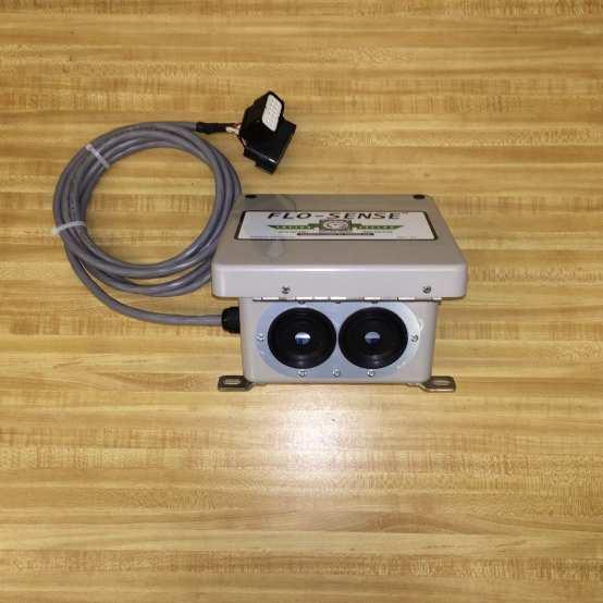
Installation and Operation Manual Flo-Sense NH 3 Flow Indicator System
|
|
|
- Basil Hubbard
- 5 years ago
- Views:
Transcription
 can cause SERIOUS INJURY OR DEATH. 2. Before installation or removal of any sensor, the system must be purged of all product. 3. Personal Protective Equipment (PPE), safety gloves, goggles and clothing should be worn.")
1 Installation and Operation Manual Flo-Sense NH 3 Flow Indicator System September 2013 Form FVC098 - Rev 02 IMPORTANT: KEEP THIS DOCUMENT WITH THE PRODUCT UNTIL IT REACHES THE END USER. 1. Contact with or inhalation of Liquid Anhydrous Ammonia (NH 3 ) can cause SERIOUS INJURY OR DEATH. 2. Before installation or removal of any sensor, the system must be purged of all product. 3. Personal Protective Equipment (PPE), safety gloves, goggles and clothing should be worn. 4. For proper handling and storage of NH 3, refer to ANSI Standard K61.1 and NFPA Pamphlet An abundant supply of fresh water should be available to provide immediate first aid treatment for exposure to NH To ensure long term safe operation, the manufacturer recommends that under normal service conditions this product should be inspected at least once every year and be repaired or replaced as required. TOOLS REQUIRED: Safety Equipment (i.e. Gloves, Goggles, and Clothing), 5/8 Wrench or Socket, cable ties. Installation Instructions Step 1: If installing the Flo-Sense system on an existing toolbar, disconnect any previously installed knife hoses from the hose barbs on the manifold(s). Remove the hose barbs from the manifold(s). Wherever a hose barb was previously located, install a Sensor (See Fig. 1). Re-install the hose barbs and hoses (See Fig. 1). If installing the Flo-Sense system on a new toolbar, install the Sensors on the manifold(s) in the configuration that you would normally use. Install the hose barbs and hoses (See Fig. 1). Step 2: Mount the Junction Box to the toolbar using cable ties or other appropriate methods. See Fig. 2 for proper mounting orientation and clearances for the Junction Box. If the Junction Box is mounted improperly, water may enter the box and damage the system. Open the Junction Box. Select an appropriate length of Sensor Cable (available in 8 ft., 16 ft., and 20 ft. lengths) to connect the Sensor to the Junction Box. There should be enough length of cable such that there is no tension in the cable when connected. Step 3: Connect the male weather-tight electrical connector from the Sensor to the female weather-tight connector on the Sensor Cable. Route the white male connector of the Sensor Cable through either of the grommet openings at the bottom of the Junction Box and connect it to the appropriate panel connector number. The grommet can accommodate up to 14 cables through each opening. Some stretching of the openings is expected. Note the channel number with which each knife is associated for ease of location once a plugged condition occurs. Secure any extra cable such that it will not interfere with the normal operation of the toolbar and does not pose a safety risk (e.g. being dragged along the ground). For ease of location once a plugged condition occurs, number each Sensor Cable and knife with the appropriate channel number using the numbered tags provided. Step 4: Mount the In-Cab Panel at a convenient location in the tractor cab, preferably in a convenient line of sight for the tractor operator. Connect the Flo-Sense Monitor to a 12 volt power supply using the cigarette lighter adapter provided (see Fig. 3). Step 5: Once the tractor and toolbar are connected, connect the Flo-Sense Monitor to the Junction Box via the In-Line Connector (See Fig. 3). Secure any extra cable such that it will not interfere with the normal operation of the toolbar or tractor and does not pose a safety risk. Step 6: NOTE: An inline strainer with a 40 mesh screen and a magnet must be installed in the tool bar piping just prior to the distributor manifold(s) to ensure proper Sensor operation. Rust or bits of thread sealant may obstruct the precision guidance of the internal mechanisms in the Sensor and cause Sensor errors. Operating Instructions System Requirements The Flo-Sense system has been designed to operate between 0.5 gpm and 2.5 gpm of anhydrous ammonia per knife. A minimum flow of 0.5 gpm per knife is required for proper operation. The Flo-Sense Monitor has space for 27 knives. Any indicator light not connected to a sensor will not light up under any circumstance. Begin Application of NH 3 Step 1: Switch the toggle on the Flo-Sense Monitor to the ON position. The green LED on the toggle will be lit if the monitor is correctly attached to a power supply. If NH3 is not flowing, or is flowing at a rate of less than 0.5 gpm per knife, the indicator light for each attached Sensor will remain on. Step 2: As the flow of NH3 increases, each indicator light will turn off, indicating that there is sufficient flow through the knife to actuate the internal mechanism of the Sensor. If a knife becomes plugged or the flow rate through the knife becomes less than 0.5 gpm, its associated indicator light will turn on. Because all of the indicator lights (if connected to a Sensor) will turn on when flow to the toolbar is stopped, the tractor operator should take careful note of which knife or knives is plugged while NH 3 is flowing. Form FVC098-Rev 02 GEARS of 5
2 System Maintenance If the indicator panel or channel map (located on the inside of the cover of the junction box) become illegible due to dust build-up, clean with a damp cloth. Do not spray cleaner on the indicator panel directly. If debris or build-up affects sensor operation, remove the sensor from the system (WARNING: Follow proper safety procedures when removing the sensor from the system to prevent serious injury or death) and flush with water or a mild solvent. DO NOT take the sensor apart or attempt to remove debris by forceful means, as this may damage the sensor and render it inoperable. If a significant amount of metal debris is stuck to the embedded magnet in the sensor poppet, replace the sensor. Check the electrical connections for wear and damage each season before start-up to ensure proper operation. Replace the associated cable(s) if significant damage is noted. Check the sensors for exterior damage each season before start-up. Replace the sensor(s) if significant damage is noted. Trouble-Shooting 1. No indicator light at zero flow Check electrical continuity from the indicator panel (make sure that all connections are secure and no wires are damage) Check for large debris or obstructions in the sensor Check for exterior damage to the sensor 2. Indicator light never turns off Check for obstructions or large debris in the manifold or sensor Check for obstructions or pinches in the line connecting the sensor to the knife Check for exterior damage to the sensor Check that flow to the sensor is greater than 1/2 gallon per minute NH 3 3. Indicator light flickers Check for obstructions or pinches in the line connecting the sensor to the knife Check that flow to the sensor is greater than 1/2 gallon per minute NH 3 4. No power to indicator panel Check the 5 amp fuse in the cigarette lighter adapter by unscrewing the tip of the adapter User Safety Responsibility Statement for All Parker Products FAILURE OR IMPROPER SELECTION OR IMPROPER USE OF THE PRODUCTS DESCRIBED HEREIN OR RELATED ITEMS CAN CAUSE DEATH, PERSONAL INJURY AND PROPERTY DAMAGE. This document and other information from Parker-Hannifin Corporation, its subsidiaries and authorized distributors provide product or system options for further investigation by users having technical expertise. The user, through its own analysis and testing, is solely responsible for making the final selection of the system and components and assuring that all performance, endurance, maintenance, safety and warning requirements of the application are met. The user must analyze all aspects of the application, follow applicable industry standards, and follow the information concerning the product in the current product catalog and in any other materials provided from Parker or its subsidiaries or authorized distributors. To the extent that Parker or its subsidiaries or authorized distributors provide component or system options based upon data or specifications provided by the user, the user is responsible for determining that such data and specifications are suitable and sufficient for all applications and reasonably foreseeable uses of the components or systems. Form FVC098-Rev 02 GEARS of 5

3 FIGURE 1 Form FVC098-Rev 02 GEARS of 5


4 FIGURE 2 Form FVC098-Rev 02 GEARS of 5
5 FIGURE 3 Form FVC098-Rev 02 GEARS of 5
Installation, Operation & Maintenance Manual for Flo-Max II Coupler Model FM126
 Installation, Operation & Maintenance Manual for Flo-Max II Coupler Model FM126 December 2015 Form FVC 073 - Rev 09 IMPORTANT: KEEP THIS DOCUMENT WITH THE PRODUCT UNTIL IT REACHES THE END USER. 1. Contact
Installation, Operation & Maintenance Manual for Flo-Max Couplers Model FM
 (214) 357-4591 INCORPORATED (800) 345-8105 DALLAS TEXAS Installation, Operation & Maintenance Manual for Flo-Max Couplers Model FM1.25-1000 Feb. 2004 Form FVC 062 - Rev 01 KEEP THIS DOCUMENT WITH THE PRODUCT
Installation, Operation & Maintenance Manual for Flo-Max Couplers Model FM
 (24) 357-459 INCORPORATED (800) 345-805 DALLAS TEXAS Installation, Operation & Maintenance Manual for Flo-Max Couplers Model FM.25-000 February 2008 Form FVC 062 - Rev 08 KEEP THIS DOCUMENT WITH THE PRODUCT
Installation, Operation & Maintenance Manual for Flo-Max II Coupler Model FM126
 IMPORTANT: The Flo-Max II coupler is designed to disconnect the nurse tank hose from a tool bar before the straight pull force on the hose exceeds 450 pounds. Upon disconnect, swing checks in both halves
WARNING User Responsibility
 WARNING User Responsibility FAILURE OR IMPROPER SELECTION OR IMPROPER USE OF THE PRODUCTS DESCRIBED HEREIN OR RELATED ITEMS CAN CAUSE DEATH, PERSONAL INJURY AND PROPERTY DAMAGE. This document and other
Product Features. Easy installation. Pump adds only 3.3 to the overall assembly height. 60 GPH (227 LPH) flow rate while in priming mode.
 flow rate while in priming mode.") Primer Pump Kits RKP1912 (12 vdc) and RKP1924 (24 vdc) Instruction Part Number 14356 Rev C Primer pump kits are an innovative and proprietary system consisting of a prescreen filter, a flow by-pass circuit,
Primer Pump Kits RKP1912 (12 vdc) and RKP1924 (24 vdc) Instruction Part Number 14356 Rev C Primer pump kits are an innovative and proprietary system consisting of a prescreen filter, a flow by-pass circuit,
Installation and Startup Manual Hydraulic Pumps Series VP1-095 /-110/ -130
 Visit our homepage for additional support parker.com/pmde Installation and Startup Manual Hydraulic Pumps Series VP1-095 /-110/ -130 Effective: May 01, 2015 Supersedes: January 01, 2013 Important installation
Flow Control Valves Check Valves Gauge Control Valves. Colorflow Valves
 Check Valves Gauge Control Valves Colorflow Valves Colorflow and Ball Valves Industrial Flow Control, Check, Gauge Control Catalog HY14-3300/US Colorflow and Ball Valves Fully guided poppets are used on
45 VALVE SERIES. 2-Position 4-Way 5-Ports, Installation & Service Instructions. Valve with Stem Operator, Installation & Service Instructions
 (02/20/8) Pneumatic Division Richland, Michigan USA www.parker.com/pneumatics Document Number V275CP V280CP V284CP V32CP 45 VALVE SERIES Description 3-Position 4-Way 5-Ports, Installation & Service Instructions
WARNING User Responsibility
 WARNING User Responsibility FAILURE OR IMPROPER SELECTION OR IMPROPER USE OF THE PRODUCTS DESCRIBED HEREIN OR RELATED ITEMS CAN CAUSE DEATH, PERSONAL INJURY AND PROPERTY DAMAGE. This document and other
ME217PIB / ME503PIB SMART INTERLOCK TECHNOLOGY ACME ADAPTER INTERLOCK BRACKET INSTALLATION AND OPERATING INSTRUCTIONS
 ME217PIB / ME503PIB SMART INTERLOCK TECHNOLOGY ACME ADAPTER INTERLOCK BRACKET INSTALLATION AND OPERATING INSTRUCTIONS ME825-16 / ME825-10 (Not Included) ME217PIB / ME503PIB ME229F5-1 / ME449F8-1 (Not Included)
ACHL Series Pump. Operation and Maintenance Manual Air Driven, Hand Operated High Pressure Liquid Pump
 ACHL Series Pump Operation and Maintenance Manual Air Driven, Hand Operated High Pressure Liquid Pump Catalog: 02-9245ME February 2013 Model # Serial # Drawing # Order # Mfg. Date Table of Contents page
Sandwich Valves Series CP
 Technical Information General Description. pilot operated check valves are designed for maximum flow rates. The valves are typically used in combination with spool type directional control valves to ensure
Electric Expansion Valves
 Electric Expansion s Bulletin 100-20-1, January 2011 Page 2 Bulletin 100-20-1UK This supplement to Bulletin 100-20 (September 2008) details the updated Sporlan series of Electric Expansion s. Built on
ME868PIB SMART INTERLOCK TECHNOLOGY TURBO FLO LE PROXIMITY INTERLOCK BRACKET INSTALLATION AND OPERATING INSTRUCTIONS
 ME868PIB SMART INTERLOCK TECHNOLOGY TURBO FLO LE PROXIMITY INTERLOCK BRACKET INSTALLATION AND OPERATING INSTRUCTIONS ME868-16 Turbo-Flo LE Adapter (Not Included) ME441F8 Cap (Not Included) ME868PIB Application:
DY Series 1-Piece Ball Valves. Catalog 1001C-A. July 2012 欧陆传动
 DY Series 1-Piece Ball Valves Catalog 1001C-A July 2012 欧陆传动 aerospace climate control electromechanical filtration fluid & gas handling hydraulics pneumatics process control sealing & shielding Contents
M-3025CB-AV Fuel Pump
 SAVE THESE INSTRUCTIONS M-3025CB-AV Fuel Pump Owner s Manual TABLE OF CONTENTS General Information... 2 Safety Instructions... 2 Installation... 3 Operation... 4 Maintenance... 4 Repair... 5 Troubleshooting...
HM860 FLOWMETER OPERATOR S MANUAL DO NOT USE OR OPERATE THIS EQUIPMENT UNTIL THIS MANUAL HAS BEEN READ AND THOROUGHLY UNDERSTOOD
 HM860 FLOWMETER OPERATOR S MANUAL DO NOT USE OR OPERATE THIS EQUIPMENT UNTIL THIS MANUAL HAS BEEN READ AND THOROUGHLY UNDERSTOOD PART NUMBER 393-008-020 Rev. C Table of Contents TABLE OF CONTENTS 393-008-020
Sporlan Gas Cooler/ Flash Gas Bypass Valves
 Sporlan Gas Cooler/ Flash Gas Bypass Valves For Transcritical CO 2 (R-744) Applications August 14 / Bulletin 100-80 Page 2 Bulletin 100-80 Bulletin 100-80 Page 3 GAS COOLER/FLASH GAS BYPASS VALVES The
Figure 1: HB Series Ball Valve Cross Sectional View DISASSEMBLY WARNING: MAKE CERTAIN THE SYSTEM IN WHICH THE VALVE IS INSTALLLED IS EXHAUSTED OF ALL
 Maintenance Instructions MI-142 Revision - HB Series Ball Valve MAXIMUM ALLOWABLE WORKING PRESSURES Table 1 Maximum Allowable Working Pressure versus Seat Material Seat Stainless Steel Material Body Material
Pulse Width Modulation Valves. Models SPW-0 thru -7
 November 2017 Bulletin / Bulletin 30-30 30-30 Page 1 Pulse Width Modulation s Models SPW-0 thru -7 Page 2 Bulletin 30-30 Pulse Width Modulation s For Refrigerant Flow Control in Direct Expansion HFC, HCFC
Quick Coupling Products
 Quick Coupling Products Quick Couplings, Swivels, Valves, Diagnostic Equipment Catalog 3800 USA February 2014 Locations Grantsburg, WI Chetek, WI Union City, PA FAILURE OR IMPROPER SELECTION OR IMPROPER
Sofa Slideout Assembly OWNER'S MANUAL. Rev: Page 1 Sofa Slideout Owners Manual
 Sofa Slideout Assembly OWNER'S MANUAL Rev: 06.14.2016 Page 1 Sofa Slideout Owners Manual TABLE OF CONTENTS Warning, Safety, and System Requirement Information 3 Product Information 3 Prior to Operation
GEN 3 LED LIGHT BAR INSTALLATION MANUAL Model 7840-A 44"
 GEN 3 LED LIGHT BAR INSTALLATION MANUAL Model 7840-A 44" Your purchase of a Wolo warning light bar is the perfect choice to compliment your vehicle. Wolo s warning lights are manufactured with the finest
Duramax Lift Pump Kit 9-11 PSI Installation Instructions P/N# D
 2001-10 Duramax Lift Pump Kit 9-11 PSI Installation Instructions P/N# 1050320D PLEASE READ ALL INSTRUCTIONS CAREULLY BEORE INSTALLATION Kit Contents 1500365-P2 1500330-D lowmax Lift Pump V3 lowmax Wiring
INFINITY-3 STROBE LED BAR INSTALLATION MANUAL 7700 SERIES
 INFINITY-3 STROBE LED BAR INSTALLATION MANUAL 7700 SERIES Your purchase of a Wolo warning light is the perfect choice to compliment your vehicle. Wolo s warning lights are manufactured with the finest
INFINITY-1 HALOGEN LIGHT BAR INSTALLATION MANUAL 7000 SERIES
 INFINITY-1 HALOGEN LIGHT BAR INSTALLATION MANUAL 7000 SERIES Your purchase of a Wolo warning light is the perfect choice to compliment your vehicle. Wolo s warning lights are manufactured with the finest
Manifold Accessories. Catalog 4190-FP-ACC May 2007
 Manifold Accessories Catalog 4190-FP-ACC May 2007 Contents Page 3 Lapped joint tube adaptors (LJ) Page 4 Flange to compression connectors (FC) Page 5 Kidney flanges to compression connectors (KF) Page
Colorflow and Ball Valves. Industrial Flow Control, Check, Gauge Control. Catalog HY /US
 Colorflow and Industrial Flow Control, Check, Gauge Control Catalog HY14-3300/US Colorflow and Fully guided poppets are used on Colorflow valves rather than the less durable ball-check type construction.
MEP801PIK / MEP801PIKL / MEP801PIH / MEP801PIHL SMART INTERLOCK TECHNOLOGY HOSE END VALVE HOLSTER INSTALLATION AND OPERATING INSTRUCTIONS
 MEP801PIK / MEP801PIKL / MEP801PIH / MEP801PIHL SMART INTERLOCK TECHNOLOGY HOSE END VALVE HOLSTER INSTALLATION AND OPERATING INSTRUCTIONS Application: Designed to provide a durable and convenient receptacle
Needle Valves (VQ Series) Catalog 4110-VQ Revised, July 2001
 Catalog 4110-VQ Revised, July 2001") Needle Valves (VQ Series) Catalog 4110-VQ Revised, July 2001 Introduction Parker VQ Series Needle Valves are the right combination of performance and value for manual or pneumatic onoff control in moderate
Needle Valves (VQ Series) Catalog 4110-VQ Revised, July 2001 Introduction Parker VQ Series Needle Valves are the right combination of performance and value for manual or pneumatic onoff control in moderate
400 Series Spin-on Fuel Filter/Water Separators
 00 Series Spin-on Fuel Filter/Water Separators Instruction Part Number 09 Rev G 00 Series fuel filter/water separators are designed to handle today s tough fuel filtration problems and can be used anywhere
Operation and Maintenance Manual
 Operation and Maintenance Manual Piston Actuated Air Operated Valve for c1s/c2s/o1s/o2s model operators 10V SW 10SM 20SM 30VM 40VM 60VM 100VM 150V series valves Parker Autoclave Engineers Instrumentation
Type N550 Emergency Shutoff Valves. Instruction Manual. Type N550 Emergency Shutoff Valves. Introduction. Specifications. Scope of Manual.
 Type N550 Emergency Shutoff Valves Type N550 Emergency Shutoff Valves Failure to follow these instructions or to properly install and maintain this equipment could result in an explosion and/or fire causing
120RMAM Marine Series Fuel Filter/Water Separators
 10RMAM Marine Series Fuel Filter/Water Separators Instruction Part Number 1945 Rev A Overview The 10RMAM fuel filter/water separator features 1/4-18 NPTF inlet and outlet fuel ports and a unitized mounting
Type N550 Snappy Joe Emergency Shutoff Valves
 Instruction Manual MCK-1149 Type N550 March 2010 Type N550 Snappy Joe Emergency Shutoff Valves Failure to follow these instructions or to properly install and maintain this equipment could result in an
Product Features: Removes 99% of free water. Available with 2, 10, or 30 micron Aquabloc II media
 120A and 120B Series Fuel Filter/Water Separators Instruction Part Number 10219 Rev B Overview: 120A and 120B fuel filter/water separators are designed to be installed on the suction side of the fuel system
Pneumatic Division North America Richland, MI 49083
 Pneumatic Division North America Richland, MI 08 Installation Instructions: V-0P /8" Valvair II/A Series Valves Single Operated ISSUED: May, 00 Supersedes: November, 8 ECN #6 Rev. 6 WARNING To avoid unpredictable
High Pressure Gear Pumps & Motors Series PZG Pumps Series MZG Motors
 High Pressure Gear Pumps & Motors Series PZG Pumps Series MZG Motors Bulletin 650-Z1 High Pressure Gear Pumps and Gear Motors for today s demanding mobile and industrial applications. The PZG and MZG Series
Installation Instructions
 Outdoor plit Flow Center Kit FCP11BDO (1 pump) FCP21BDO (2 pumps) For plit Geothermal Heat Pump models GZ & H Installation Instructions NOTE: Read the entire instruction manual before starting the installation.
STEP-BY-STEP INSTALLATION GUIDE
 Battery Backup System STEP-BY-STEP INSTALLATION GUIDE Operating Instructions & Parts Manual ESP25 Please read and save these instructions. Read carefully before attempting to assemble, install, operate
MagnePump. Recirculation MagnePumps. At a Glance:
 MagnePump Recirculation MagnePumps Parker Autoclave Engineers MagnePumps eliminate or reduce many of the problems associated with conventional pumps, such as leakage, contamination and packing heat generation.
PRO PRO20-115RD 115-Volt AC. PRO Volt AC OWNER'S MANUAL SAVE THESE INSTRUCTIONS
 OWNER'S MANUAL SAVE THESE INSTRUCTIONS PRO20-115 PRO20-115RD 115-Volt AC PRO20-115AD Automatic Diesel Nozzle PRO20-115MD Manual Diesel Nozzle PRO20-115PO Pump Only PRO20-115RD For Remote Dispensing Systems
*Phillips Screwdriver *10mm Nut Driver *10mm Socket *Ratchet *Three Inch Putty Knife *Panel Removal Tool *10mm Wrench CONTENTS:
 TOOLS REQUIRED: *Phillips Screwdriver *10mm Nut Driver *10mm Socket *Ratchet *Three Inch Putty Knife *Panel Removal Tool *10mm Wrench CONTENTS: 1EA. SUBWOOFER ASSEMBLY 1EA. 100 WATT AMP ASSEMBLY 1EA. WIRE
G8 Portable Fuel Transfer Pump Owner s Manual
 G8 Portable Fuel Transfer Pump Owner s Manual GENERAL INFORMATION This pump is designed for use only with gasoline (up to 15% alcohol blends such as E15), diesel fuel (up to 20% biodiesel blends such as
Air Conditioner for M915 A0/A1 Truck
 RD-2-4530-0 Air Conditioner for M915 A0/A1 Truck INSTALLATION INSTRUCTIONS Install refrigerant compressor per instructions provided with compressor mount kit. CAUTION: Edges of sheet metal can be sharp!
INSTALLATION MANUAL 2000WCY
 INSTALLATION MANUAL 2000WCY Pressure Cleaning System spraymastertech.com Spray Master Technologies is a quality product line of Assembled Products Corp. 115 E. Linden Rogers, Arkansas 72756 USA (479) 636-5776
Sprayer Control. Manual for SprayLink Cable Installations. Tank. Jet Agitator. Agitator Valve. Diaphragm Pump. Pressure Transducer.
 Sprayer Control Plumbing & Installation Manual for SprayLink Cable Installations Tank Jet Tank Shut-Off Diaphragm Pump Electric Ball s Transducer Strainer Relief Regulating Copyrights 2012 TeeJet Technologies.
Installation instructions
 Installation instructions Akrapovič Exhaust System: Slip-On for the Porsche 911 Carrera (type 991) Porsche 911 Carrera S (type 991) Porsche 911 Carrera 4 (type 991) Porsche 911 Carrera 4S (type 991) Please
75500MAX Series and 75500MAXM Series
 75500MAX Series and 75500MAXM Series Marine Fuel Filter/Water Separators Instruction Part Number 15349 Rev E Racor Turbine Series fuel filter/ water separators protect the precision components of your
Introduction Parker are designed for uni-directional flow control of fluids and gases in industries such as chemical processing, oil and gas productio
 Check Valves (CO Series) Catalog 4130-CO Revised, June 2001 Introduction Parker are designed for uni-directional flow control of fluids and gases in industries such as chemical processing, oil and gas
Rotary Plug Valves (PR Series) Catalog 4126-PR Revised, July 2003
 Catalog 4126-PR Revised, July 2003") Rotary Plug Valves (PR Series) Catalog 4126-PR Revised, July 2003 PR Series Rotary Plug Valves Introduction Parker PR Series Plug Valves provide positive leak tight shut-off, high flow capacity, and quick
Rotary Plug Valves (PR Series) Catalog 4126-PR Revised, July 2003 PR Series Rotary Plug Valves Introduction Parker PR Series Plug Valves provide positive leak tight shut-off, high flow capacity, and quick
Features and Benefits Wide Bottom: Translucent Bottle: 2 1/2 Gallon Bottle: Removable Bottle: Large cap: 15 Feet of Coiled Hose:
 12 Volt Battery Powered Sprayer This unit uses a lead acid battery. The charge capacity of the battery can be greatly diminished if fully discharged. Care should be given to charge the battery between
Stay-IN-Play with Panic Stop Braking
 INSTALLATION INSTRUCTIONS TOWED VEHICLE BRAKING SYSTEM Stay-IN-Play with Panic Stop Braking SMI Manufacturing, Inc. P.O. Box 14040 Evansville, IN 47728 1-800-893-3763 www.smibrake.com SIP0906 Model SIP0603
275 Beacon 12v MODELS PERMANENT, MAGNETIC MOUNT BEACONS
 INSTALLATION & OPERATION MANUAL 275/275AH/275ASH/ 275AMH BEACON 275 Beacon 12v MODELS PERMANENT, MAGNETIC MOUNT BEACONS Contents: Introduction... 2 Unpacking & Pre-Installation... 2 Installation & Mounting...
DISPLACEMENT PUMP INSTRUCTIONS-PARTS LIST Rev. K. Model , Series A Model , Series B Model , Series A
 INSTRUCTIONS-PARTS LIST INSTRUCTIONS This manual contains important warnings and information. READ AND KEEP FOR REFERENCE. DISPLACEMENT PUMP 308190 Rev. K 3000 psi (210 bar) MAXIMUM WORKING PRESSURE Model
LOOKOUT LED LIGHT BAR INSTALLATION MANUAL 7900 SERIES
 LOOKOUT LED LIGHT BAR INSTALLATION MANUAL 7900 SERIES Your purchase of a Wolo warning light is the perfect choice to compliment your vehicle. Wolo s warning lights are manufactured with the finest materials.
150 PSI ILLUMINATED DASH PANEL GAUGE KIT
 150 PSI ILLUMINATED DASH PANEL GAUGE KIT PART NO. 10061 (For Use with 20/30 Amp Systems) PART NO. 20062 (For Use with 30/40 Amp Systems) IMPORTANT: It is essential that you and any other operator of this
M-1115S Series Fuel Pump
 SAVE THESE INSTRUCTIONS M-1115S Series Fuel Pump Owner s Manual TABLE OF CONTENTS General Information...2 Safety Instructions...2 Installation...3 Operation...4 Maintenance...5 Repair...5 Troubleshooting...9
GRAIN CART RETROFIT TRACK SLIDE-IN-HITCH SCALE SYSTEM
 GRAIN CART RETROFIT TRACK SLIDE-IN-HITCH SCALE SYSTEM Instructions This manual is copyrighted by Scale-Tec. Redistribution or copy of this manual or portions of this manual must be approved through Scale-Tec
Trilogy. Linear Motors and Positioners. Rometec srl - - Rometec srl - - Rometec srl -
 Rometec srl - www.rometec.it Trilogy Linear Motors and Positioners Rometec srl - www.rometec.it Rometec srl - www.rometec.it WARNING USER RESPONSIBILITY FAILURE OR IMPROPER SELECTION OR IMPROPER USE OF
180 Lake Ave North Paynesville, MN Phone: (320) MASTER MANUFACTURING MASTER GARDNER
 MASTER MANUFACTURING MASTER GARDNER") 180 Lake Ave North Paynesville, MN 56362 Phone: (320) 340-6464 www.master-mfg.com MASTER MANUFACTURING MASTER GARDNER Part Number PCD-E3-009B-MM July 2017 Note: Do not return product to the distributor/dealer
180 Lake Ave North Paynesville, MN 56362 Phone: (320) 340-6464 www.master-mfg.com MASTER MANUFACTURING MASTER GARDNER Part Number PCD-E3-009B-MM July 2017 Note: Do not return product to the distributor/dealer
NOTE. Installation and Service Manual Dual Planetary Gearmotor Slim Rack Slide Out System
 Installation & Service Manual Slim Rack In-Wall Slide Out System Control Box Part Number 1510000199 Content Copyright LCI/Power Gear Issued: December 2014 #3010002588, Rev. 0E Installation and Service
MOTORVAC TECHNOLOGIES INC. TRANSTECH-1000 Transmission Service System
 MOTORVAC TECHNOLOGIES INC. TRANSTECH-1000 Transmission Service System OPERATOR MANUAL UNIT MODEL NUMBER 500-1101 TRANSTECH 1000 OPERATOR MANUAL - 100-1101 Rev. A, 2006 Table of Contents Introduction...3
ELECTRIC SPRAYER CONTROL SYSTEM OWNERS MANUAL
 -- AB00 Rev. 0 ELECTRIC SPRAYER CONTROL SYSTEM OWNERS MANUAL REPLACEMENT PARTS READ complete manual CAREFULLY BEFORE attempting operation. DEMCO Dethmers Mfg. Co. P.O. Box 0 0th Street Boyden, IA PH: ()
Check Valves (CO Series) Catalog 4130-CO Revised, June 2001
 Catalog 4130-CO Revised, June 2001") Check Valves (CO Series) Catalog 4130-CO Revised, June 2001 Introduction Parker are designed for uni-directional flow control of fluids and gases in industries such as chemical processing, oil and gas
Check Valves (CO Series) Catalog 4130-CO Revised, June 2001 Introduction Parker are designed for uni-directional flow control of fluids and gases in industries such as chemical processing, oil and gas
Endeavor Fertilizer Controler" Electric Pump Fertilizer System for John Deere GS2 with Servo Control
 Endeavor Fertilizer Controler" Electric Pump Fertilizer System for John Deere GS with Servo Control We Can Also Interface with These Popular Third Party Controllers: Trimble - EZ Boom & Field IQ Ag Leader
Sinclair Collins. Process Control Valves. For Steam, Hot and Cold Liquids -40 to 450 F up to 500 psi. Catalog SCV-100/USA April 2001
 Sinclair Collins Process Control Valves For Steam, Hot and Cold Liquids -40 to 450 F up to 500 psi April 2001 The Diaphragm Operated Valves on the following pages are designed for directing, diverting
Installation & Service Manual
 Installation & Service Manual for M² Sync Slideout Control Box #1510000122 CONTENTS Introduction Installation Installation Problems Program Mode Operation Mode Preventative Maintenance Fault Diagnostics
TABLE OF CONTENTS. 1. Before You Begin 3 Disclaimer 3 What Is Included 3 Optional Accessories 3 Unpacking Instructions 3 Claims 3 Contact Us 3
 Page 1 of 25 TABLE OF CONTENTS 1. Before You Begin 3 Disclaimer 3 What Is Included 3 Optional Accessories 3 Unpacking Instructions 3 Claims 3 Contact Us 3 2. Safety Information 4 Safety Notes 4 Rules for
Service Manual Series F12
 Bulletin HY30-5504-M1/UK Effective: June, 2006 Supersedes: August, 2003 List of contents Page General information...3 Specifications...4 Disassembling...5-10 Assembling...11-16 Change of shaft seal...17
xtablet T7000 Vehicle Mount Kit
 xtablet T7000 Vehicle Mount Kit Installation & Users Guide Last Updated: January 19, 2012 Find the latest updates in the Support section in the MobileDemand website at: www.ruggedtabletpc.com. Questions?
Operator s Manual. Sabre Crop Divider
 Operator s Manual Sabre Crop Divider Canadian Agri Technologies Inc. 47 Halparin Drive Winnipeg, MB. R3X 1Z9 ph. 204 992.2484 fax. 204 237.0552 www.sabredivider.com TOLL FREE PARTS LINE 1 866 792-8437
Snap-tite Quick Disconnect Couplings for Applications Requiring Virtually No Air Inclusion or Spillage
 Snap-tite Quick Disconnect Couplings for Applications Requiring Virtually No Air Inclusion or Spillage 8- Series For Pressures to 0 psi ( bar) 9 Series For Pressures to 0 psi ( bar) Featuring: Low pressure
Installation instructions
 Installation instructions Akrapovič Exhaust System: Electro Actuator Kit for the Porsche Cayenne Turbo (type 958 FL) ENGLISH Version 1.0 03/2016 www.akrapovic.com Installation instructions Akrapovič Exhaust
Pneutronics. Miniature Proportional Valves. Catalog PND-MPV-001/US January 2007
 Pneutronics Miniature Proportional Valves January 2007 Non-Thermally Compensated Proportional Valve HF 200 Miniature Ultra High Flow Proportional Valve HF 200 is a high flow proportional valve that provides
STYLE 3462 FORESTRY BUMPER MONITOR INSTALLATION, OPERATING and MAINTENANCE INSTRUCTIONS
 STYLE 3462 FORESTRY BUMPER MONITOR INSTALLATION, OPERATING and MAINTENANCE INSTRUCTIONS The following is intended to provide the basic instructions for installation, operating and maintenance of the 3462
Installation Instructions
 Outdoor plit Flow Center Kit FCP11BDO (1 pump) FCP21BDO (2 pumps) For plit Geothermal Heat Pump models GZ & H Installation Instructions NOTE: Read the entire instruction manual before starting the installation.
GPS AutoSteer System Installation Manual
 GPS AutoSteer System Installation Manual Supported Vehicles Case IH Vehicles Case 2577 Combines Case 2588 Combines Accuguide Ready PN: 602-0233-01-A LEGAL DISCLAIMER Note: Read and follow ALL instructions
Page 1 of 19. Part# /10/2006
 Part# 1002733-01 10/10/2006 This manual contains important information concerning the installation and operation of the gun washers listed above. Read manual thoroughly and keep for future reference INSTRUCTIONS
Installation instructions
 Installation instructions Akrapovič Exhaust System: Slip-On for the Porsche Cayenne Turbo (type 958 FL) ENGLISH Version 1.0 03/2016 www.akrapovic.com Installation instructions Akrapovič Exhaust System:
Thermostatic and Automatic Expansion Valves
 aerospace climate control electromechanical filtration fluid & gas handling hydraulics pneumatics process control sealing & shielding Thermostatic and Automatic Expansion Valves Catalog E-1, July 2012
Page 1 of 12. Part# /30/2016
 Part# 1007480-02 9/30/2016 This manual contains important information concerning the installation and operation of the gun washers listed above. Read manual thoroughly and keep for future reference. INSTRUCTIONS
Condensate Pump. Installation and Safety Instructions CP-22 CP CP-22LP CP-22LP-230
 Condensate Pump Installation and Safety Instructions CP-22 CP-22-230 CP-22LP CP-22LP-230 CP-22 CP-22LP CP-22T CP-22LPT CP-22-230 CP-22LP-230 CP-22T-230 CP-22LPT-230 Rated Voltage 120 Volts / 60 Hz 220
Instructions for 2-row monitoring only
 Installation Instructions for CaseIH cotton picker models: Instructions for 2-row monitoring only CAUTION: Ensure the model numbers shown above correspond to the machine model. If you receive the incorrect
29048, 29049, 29050, 29051, 29052, 20953, 29054,
 July 15, 2008 Lit. No. 29225, Rev. 06 29048, 29049, 29050, 29051, 29052, 20953, 29054, 29400-2 HARNESS KIT 3-PORT ISOLATION MODULE LIGHT SYSTEM w/2-plug SYSTEM HARNESSES Installation Instructions Read
Maintenance Instructions & Parts List
 PM-PTR/LTR-C Automation Actuator Division Wadsworth, Ohio 448 October 7, 993 Rev. October 999 PTR/LTR Series Actuators Maintenance Instructions & Parts List Provide Model Number and Serial Number When
Hydro-Sync Slide-Out System
 Hydro-Sync Slide-Out System SERVICE MANUAL Rev: 08.14.2018 Hydro-Sync Slide-out System Service Manual TABLE OF CONTENTS Safety Information 3 Product Information 3 Operation 4 Extending Slide-Out Room 4
MODEL 900 IMPELLER-TYPE FLOW METER
 MODEL 900 IMPELLER-TYPE FLOW METER - For Water Applications - INSTALLATION & INSTRUCTION MANUAL 8635 Washington Avenue Racine, Wisconsin 53406 Toll Free: 800.235.1638 Phone: 262.639.6770 Fax: 262.417.1155
ONBOARD AIR HOOKUP KIT
 ONBOARD AIR HOOKUP KIT PART NO. 20052 (30 amp - 110PSI on, 150PSI off) PART NO. 20053 (30 amp - 85PSI on, 105 PSI off) PART NO. 20055 (30 amp - 90 PSI on, 120 PSI off) IMPORTANT: It is essential that you
GPS AutoSteer System Installation Manual
 GPS AutoSteer System Installation Manual Supported Vehicles Case IH Combines 7010 7120 8010 8120 AFX 8010 9120 PN: 602-0283-01-A LEGAL DISCLAIMER Note: Read and follow ALL instructions in this manual carefully
RoadRelay 4. Installation Guide
 RoadRelay 4 Installation Guide RoadRelay 4 Installation Guide Bulletin No. 3401767 Revision B Copyright 2002, Cummins Inc. All rights reserved. Cummins Inc. shall not be liable for technical or editorial
Filter. Table of Contents. Section 10. Filter NOTE: This section applies to applicators with an in-out filter.
 Filter 10-1 Section 10 Filter NOTE: This section applies to applicators with an in-out filter. Table of Contents Filter...................................................... 10-1 Introduction................................................
150 Gallon 3- Point Hitch Sprayer
 150 Gallon 3- Point Hitch Sprayer Model #: K3PTH150BN22 User Manual Read this manual for complete instructions Model #: K3PTH150BN22 Table of Contents Warranty... 3 General Safety Information... 3 Hazardous
Digitrip Retrofit System for ITE K-3000, K-3000 S, K-4000 and K-4000 S Breakers
 Supersedes IL 33-858-4 Dated 05/02 Digitrip Retrofit System for ITE K-3000, K-3000 S, K-4000 and K-4000 S Breakers Digitrip Retrofit System for ITE K-3000, Digitrip Retrofit System for ITE K-3000, K-3000
Installation instructions
 Installation instructions Akrapovič Exhaust System: Slip-On for the VW GOLF GTI (type MK VII.) ENGLISH Version 1.0 02/2016 www.akrapovic.com Installation instructions Akrapovič Exhaust System: Slip-On
Product Owner s Manual. 8 GPM / 30 LPM, 12-volt Fuel Transfer Pump. Model G8P
 Product Owner s Manual EN 8 GPM / 30 LPM, 12-volt Fuel Transfer Pump Model G8P 05/2017 922130-01 Rev. A THANK YOU STATEMENT GOES HERE: Please save these instructions for future reference. Read carefully
Installation instructions
 Installation instructions Akrapovič Exhaust System: Slip-On for the Laborghini Gallardo 550-2 Coupe Laborghini Gallardo 560-4 Coupe / Spyder Laborghini Gallardo 570-4 Coupe / Spyder Congratulations on
25 GALLON ATV SPRAYER
 180 Lake Ave North Paynesville, MN 56362 Phone: 1-800-864-1649 www.master-mfg.com MASTER MANUFACTURING 25 GALLON ATV SPRAYER SAP-A1-025A-MM Revision 2 Nov. 2015 Note: Do not return product to the distributor/dealer
POWERED RUNNING BOARDS INSTALLATION MANUAL
 POWE RUNNING BOARDS INSTALLATION MANUAL Level of Difficulty Moderate Parts List 1 Driver / left running board* 1 Passenger / right running board* 4 Mounting bracket, standard 2 Mounting bracket, middle