CS/ECE 5780/6780: Embedded System Design
|
|
|
- Julie Riley
- 5 years ago
- Views:
Transcription
1 CS/ECE 5780/6780: Embedded System Design John Regehr Lecture 17: Relays and Motors
2 Introduction to Relays A relay is a device that responds to a small current or voltage change by activating a switches or other devices. Used to remotely switch signals or power. Input control usually electrically isolated from output. Input signal determines whether switch is open or closed.
3 Various Relay Configurations
4 Types of Relays Classic general-purpose relays have EM coils and can switch power. Solid-state relays (SSR) have input-triggered semiconductor switches. Reed relay has an EM coil and can switch low level DC signals. The bilateral switch uses CMOS, FET, or bifet transistors (technically not a relay but behaves similarly).

5 Types of Relays

6 Drawing of an EM Relay
7 Electromagnetic Relay Basics Input circuit is an EM coil with an Iron Core. Output switch includes two sets of silver or silver-alloy contacts (poles). One set is fixed to the relay frame, and other is located at end of leaf spring poles connected to the armature. Contacts held in normally closed position by the armature return spring. When input circuit energizes EM coil, a pull-in force is applied to the armature and normally closed contacts break while normally open contacts are made.
8 Solid State Relays Developed to solve limited life expectancy and contact bounce problems since they have no moving parts. Also, faster, insensitive to vibrations, reduced EMI, quieter, and no contact arcing. Optocoupler provides isolation between the input circuit (pseudocoil) and the triac (pseudocontact). Signal from phototransistor triggers the output triac so that it switches the load current. Zero-voltage detector triggers triac only when AC voltage is zero, reducing surge currents when triac is switched. Once triggered, triac conducts until next zero crossing.
9 Solid State Relays

10 Reed Relays
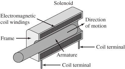
11 Solenoids
12 Pulse-Width Modulated DC Motors DC motor also has frame that remains motionless and an armature that moves in this case in a circular manner. When current flows through EM coil, magnetic force created that causes rotation of the shaft. Brushes positioned between frame and armature used to alternate the current direction through the coil so that a DC current generates a continuous rotation of the shaft. When current removed, shaft is free to rotate. Pulse-width modulated DC motor activated with fixed magnitude current but duty cycle varied to control speed.
13 Interfacing EM Relays, Solenoids, and DC Motors Interface circuit must provide sufficient current and voltage to activate the device. In off state, input current should be zero. Due to inductive nature of the coil, huge back electromotive force (EMF) when coil current is turned off. Due to high speed transistor switch, there is a large di/dt when the coil is deactivated (activation also but smaller). Voltages can range from 50 to 200V. To protect the driver electronics, a snubber diode is added to suppress the back EMF.
14 Controlling a Relay with Digital Logic

15 Relay and Motor Interfaces
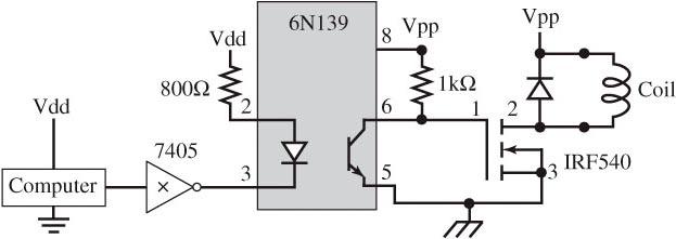
16 Isolated Interfaces
17 H-Bridge
18 Isolated H-Bridge with Direction Control
19 Stepper Motors Very popular due to inherent digital interface. Easy to control both position and velocity in an open-loop fashion. Though more expensive then ordinary DC motors, system cost is reduced as they require no feedback sensors. Can also be used as shaft encoders to measure both position and speed.

20 Stepper Motors
21 Simple Stepper Motor Interface
22 Stepper Motor Sequence PortB A A B B 10 activate deactivate activate deactivate 9 activate deactivate deactivate activate 5 deactivate activate deactivate activate 6 deactivate activate activate deactivate

23 Stepper Motor Basic Operation
24 Stepper Motor Basic Operation (cont)
25 Stepper Motor Basic Operation (cont)
26 Stepper Motor Basic Operation (cont)
27 Stepper Motor Basic Operation (cont)
28 Stepper Motor Basic Operation (cont)

29 Bipolar Stepper Motor Interface
30 Slip A slip is when computer issues a sequence change, but the motor does not move. Occurs if load on shaft exceeds available torque of motor. Can also occur if computer changes output too fast. If initial shaft angle known and motor never slips, computer can control shaft angle and speed without position sensor.
31 Stepper Motor Sequence
32 Data Structures to Control Stepper Motor const struct State{ unsigned char Out; // Output const struct State *Next[2]; // CW/CCW }; typedef struct State StateType; typedef StateType *StatePtr; #define clockwise 0 // Next index #define counterclockwise 1 // Next index StateType fsm[4]={ {10,{&fsm[1],&fsm[3]}}, { 9,{&fsm[2],&fsm[0]}}, { 5,{&fsm[3],&fsm[1]}}, { 6,{&fsm[0],&fsm[2]}}}; unsigned char Pos; // between 0 and 199 StatePtr Pt; // Current State
33 Ritual to Control Stepper Motor void Init(void){ Pos = 0; Pt = &fsm[0]; DDRB = 0xFF; }
34 Helper Functions to Control Stepper Motor void CW(void){ Pt = Pt->Next[clockwise]; // circular PORTB = Pt->Out; // step motor if(pos==199){ // shaft angle Pos = 0; // reset }else{ Pos++;}} // CW void CCW(void){ Pt = Pt->Next[counterclockwise]; PORTB = Pt->Out; // step motor if(pos==0){ // shaft angle Pos = 199; // reset }else{ Pos--;}} // CCW
35 High-Level Control of Stepper Motor void Seek(unsigned char desired){ short CWsteps; if((cwsteps=desired-pos)<0){ CWsteps+=200; } // CW steps is 0 to 199 if(cwsteps>100){ while(desired!=pos){ CCW(); } } else{ while(desired!=pos){ CW(); } } }
36 Stepper Motor as Shaft Position Sensor
37 Timing of Stepper Motor as Shaft Position Sensor
38 Today Relays Stepper motors
MANTECH ELECTRONICS. Stepper Motors. Basics on Stepper Motors I. STEPPER MOTOR SYSTEMS OVERVIEW 2. STEPPING MOTORS
 MANTECH ELECTRONICS Stepper Motors Basics on Stepper Motors I. STEPPER MOTOR SYSTEMS OVERVIEW 2. STEPPING MOTORS TYPES OF STEPPING MOTORS 1. VARIABLE RELUCTANCE 2. PERMANENT MAGNET 3. HYBRID MOTOR WINDINGS
Note 8. Electric Actuators
 Note 8 Electric Actuators Department of Mechanical Engineering, University Of Saskatchewan, 57 Campus Drive, Saskatoon, SK S7N 5A9, Canada 1 1. Introduction In a typical closed-loop, or feedback, control
AC Motors vs DC Motors. DC Motors. DC Motor Classification ... Prof. Dr. M. Zahurul Haq
 AC Motors vs DC Motors DC Motors Prof. Dr. M. Zahurul Haq http://teacher.buet.ac.bd/zahurul/ Department of Mechanical Engineering Bangladesh University of Engineering & Technology ME 6401: Advanced Mechatronics
MAGNETIC EFFECTS OF ELECTRIC CURRENT
 MAGNETIC EFFECTS OF ELECTRIC CURRENT It is observed that when a compass is brought near a current carrying conductor the needle of compass gets deflected because of flow of electricity. This shows that
Comprehensive Technical Training
 Comprehensive Technical Training For Sugar Mills Staff on Operation & Maintenance of Baggase Based HP Cogeneration System Schedule: 10 th July to 13 th July, 2017 A.C. GENERATOR Topics Covered. Introduction.
BELT-DRIVEN ALTERNATORS
 CHAPTER 13 BELT-DRIVEN ALTERNATORS INTRODUCTION A generator is a machine that converts mechanical energy into electrical energy using the principle of magnetic induction. This principle is based on the
MECHATRONICS LAB MANUAL
 MECHATRONICS LAB MANUAL T.E.(Mechanical) Sem-VI Department of Mechanical Engineering SIESGST, Nerul, Navi Mumbai LIST OF EXPERIMENTS Expt. No. Title Page No. 1. Study of basic principles of sensing and
Wheeled Locomotion. Geared Drive Vs. Direct Drive. Driving DC motors. Stepper motors. Open-loop and Closed-loop Control
 Wheeled Locomotion Geared Drive Vs. Direct Drive Driving DC motors Stepper motors Open-loop and Closed-loop Control Feedback for Close-Loop Systems Drive Configurations 1 Geared Drive Usually a DC motor
INTRODUCTION TO SENSORS, TRANSDUCERS & ACTUATORS
 INTRODUCTION Transducers play a major role in mechatronics engineering & technology. These are the basic elements that convert or transform one form of energy to another form. Let us change the word energy
Phys102 Lecture 20/21 Electromagnetic Induction and Faraday s Law
 Phys102 Lecture 20/21 Electromagnetic Induction and Faraday s Law Key Points Induced EMF Faraday s Law of Induction; Lenz s Law References SFU Ed: 29-1,2,3,4,5,6. 6 th Ed: 21-1,2,3,4,5,6,7. Induced EMF
Ch 4 Motor Control Devices
 Ch 4 Motor Control Devices Part 1 Manually Operated Switches 1. List three examples of primary motor control devices. (P 66) Answer: Motor contactor, starter, and controller or anything that control the
Special-Purpose Electric Machines
 Special-Purpose Electric Machines The machines introduced in this lecture are used in many applications requiring fractional horsepower, or the ability to accurately control position, velocity or torque.
Lecture 15 Motor Controls & Drives
 ECE 211 Lectures Page 1 Lecture 15 Motor Controls & Drives Tuesday, July 29, 2014 1:00 PM DC Motors and Control Circuits Types of DC Motors Shunt Motors Series Motors Compound Motors Permanent Magnet Motor
Magnetism and Electricity ASSIGNMENT EDULABZ. the mere presence of magnet, is called...
 Magnetism and Electricity ASSIGNMENT 1. Fill in the blank spaces by choosing the correct words from the list given below. List : magnetic field, magnetic keepers, electric bell, stop, magnetic induction,
Electrical Motor Controls Chapter 4 (Fourth Edition) Chapter 2 (Fifth Edition)
 Chapter 2 (Fifth Edition)") Electrical Motor Controls Chapter 4 (Fourth Edition) Chapter 2 (Fifth Edition) 1. Which drawing type shows physical details as seen by the eye? 2. Which drawing is similar to a pictorial drawing but has
Electrical Motor Controls Chapter 4 (Fourth Edition) Chapter 2 (Fifth Edition) 1. Which drawing type shows physical details as seen by the eye? 2. Which drawing is similar to a pictorial drawing but has
The galvanic separation of the primary or actuating circuit and the load circuits
 RELAY BASICS Relays are electro magnetically operated switches. An actuating current on a coil operates one or more galvanically separated contacts or load circuits. The electro mechanical relay is a remote
MOTOR TERMINAL CONNECTIONS
 MOTOR TERMINAL CONNECTIONS Motor Classification Most of the industrial machines in use today are driven by electric motors Motors are classified according to the type of power used (AC or DC) and the motors
Second Edition. Power Electronics. Devices and Circuits. V. Jagannathan
 Second Edition Power Electronics Devices and Circuits V. Jagannathan Power Electronics Devices and Circuits SECOND EDITION V. Jagannathan Professor and Head Department of Electrical and Electronics Engineering
Physics12 Unit 8/9 Electromagnetism
 Name: Physics12 Unit 8/9 Electromagnetism 1. An electron, travelling with a constant velocity, enters a region of uniform magnetic field. Which of the following is not a possible pathway? 2. A bar magnet
Systems: Electronics
 Systems: Electronics Resistors & Capacitors Units for resistors and capacitors size/component small large resistance ohm kilohm megaohm capacitance picofarad microfarad farad current milliampere Ampere
Lecture Outline Chapter 23. Physics, 4 th Edition James S. Walker. Copyright 2010 Pearson Education, Inc.
 Lecture Outline Chapter 23 Physics, 4 th Edition James S. Walker Chapter 23 Magnetic Flux and Faraday s Law of Induction Units of Chapter 23 Induced Electromotive Force Magnetic Flux Faraday s Law of Induction
2006 MINI Cooper S GENINFO Starting - Overview - MINI
 MINI STARTING SYSTEM * PLEASE READ THIS FIRST * 2002-07 GENINFO Starting - Overview - MINI For information on starter removal and installation, see the following articles. For Cooper, see STARTER WITH
USING WEATHERLINK FOR ALARM OUTPUT Application Note 29
 USING WEATHERLINK FOR ALARM OUTPUT Application Note 29 With Vantage Pro and Vantage Pro2 INTRODUCTION WeatherLink for Alarm Output can be incorporated in any Vantage Pro or Vantage Pro2 weather station.
Actuators are the muscles of robots.
 6.1 INTRODUCTION Actuators are the muscles of robots. Several types of actuator noteworthy? Electric motors? Servomotors? Stepper motors? Direct-drive electric motors? Hydraulic actuators? Pneumatic actuators?
EGG 101L INTRODUCTION TO ENGINEERING EXPERIENCE
 EGG 101L INTRODUCTION TO ENGINEERING EXPERIENCE LABORATORY 11: AUTOMATED CAR PROJECT DEPARTMENT OF ELECTRICAL AND COMPUTER ENGINEERING UNIVERSITY OF NEVADA, LAS VEGAS GOAL: This section combines the motor
Hybrid Stepper Motors
 DINGS Electrical & Mechanical Co., Ltd 3 Quality Performance Flexibility Price WHO IS DINGS? DINGS is a premier supplier of rotary and linear step motors. Based in the greater Shanghai, China area, we
INTRODUCTION Principle
 DC Generators INTRODUCTION A generator is a machine that converts mechanical energy into electrical energy by using the principle of magnetic induction. Principle Whenever a conductor is moved within a
Prepared By: Ahmad Firdaus Bin Ahmad Zaidi
 Prepared By: Ahmad Firdaus Bin Ahmad Zaidi A stepper motor is an electromechanical device which converts electrical pulses into discrete mechanical rotational movements. Stepper motor mainly used when
QUESTION BANK SPECIAL ELECTRICAL MACHINES
 SEVENTH SEMESTER EEE QUESTION BANK SPECIAL ELECTRICAL MACHINES TWO MARK QUESTIONS 1. What is a synchronous reluctance 2. What are the types of rotor in synchronous reluctance 3. Mention some applications
EGG 101L INTRODUCTION TO ENGINEERING EXPERIENCE
 EGG 101L INTRODUCTION TO ENGINEERING EXPERIENCE LABORATORY 8: DC MOTOR CONTROL DEPARTMENT OF ELECTRICAL AND COMPUTER ENGINEERING UNIVERSITY OF NEVADA, LAS VEGAS GOAL: This section will introduce DC motors
Page 1. Design meeting 18/03/2008. By Mohamed KOUJILI
 Page 1 Design meeting 18/03/2008 By Mohamed KOUJILI I. INTRODUCTION II. III. IV. CONSTRUCTION AND OPERATING PRINCIPLE 1. Stator 2. Rotor 3. Hall sensor 4. Theory of operation TORQUE/SPEED CHARACTERISTICS
3.0 CHARACTERISTICS E Type CO-4 Step-Time Overcurrent Relay
 41-106E Type CO-4 Step-Time Overcurrent Relay A core screw accessible from the top of the switch provides the adjustable pickup range. The IIT contacts are connected in the trip circuit to trip instantaneously.
UNIT 2. INTRODUCTION TO DC GENERATOR (Part 1) OBJECTIVES. General Objective
 OBJECTIVES. General Objective") DC GENERATOR (Part 1) E2063/ Unit 2/ 1 UNIT 2 INTRODUCTION TO DC GENERATOR (Part 1) OBJECTIVES General Objective : To apply the basic principle of DC generator, construction principle and types of DC generator.
DC GENERATOR (Part 1) E2063/ Unit 2/ 1 UNIT 2 INTRODUCTION TO DC GENERATOR (Part 1) OBJECTIVES General Objective : To apply the basic principle of DC generator, construction principle and types of DC generator.
L. Photo. Figure 2: Types CA-16 Relay (rear view) Photo. Figure 1: Types CA-16 Relay (front view)
 Photo. Figure 1: Types CA-16 Relay (front view)") Figure 1: Types CA-16 Relay (front view) Photo Figure 2: Types CA-16 Relay (rear view) Photo 2 Sub 5 185A419 Sub 6 185A443 Figure 3: Internal Schematic of the Type CA-16 bus Relay or CA-26 Transformer
Figure 1: Types CA-16 Relay (front view) Photo Figure 2: Types CA-16 Relay (rear view) Photo 2 Sub 5 185A419 Sub 6 185A443 Figure 3: Internal Schematic of the Type CA-16 bus Relay or CA-26 Transformer
Modern Motor Control Applications and Trends Tomas Krecek, Ondrej Picha, Steffen Moehrer. Public Information
 Modern Motor Control Applications and Trends Tomas Krecek, Ondrej Picha, Steffen Moehrer Content Introduction Electric Machines Basic and Advance Control Techniques Power Inverters and Semiconductor Requirements
Lecture 19 Chapter 30 Faraday s Law Course website:
 Lecture 19 Chapter 30 Faraday s Law Who cares that Faraday s Law is used here? Course website: http://faculty.uml.edu/andriy_danylov/teaching/physicsii Today we are going to discuss: Chapter 30: Section
Update. This week A. B. Kaye, Ph.D. Associate Professor of Physics. Michael Faraday
 10/26/17 Update Last week Completed Sources of Magnetic Fields (Chapter 30) This week A. B. Kaye, Ph.D. Associate Professor of Physics (Chapter 31) Next week 30 October 3 November 2017 Chapter 32 Induction
SPH3U UNIVERSITY PHYSICS
 SPH3U UNIVERSITY PHYSICS ELECTRICITY & MAGNETISM L (P.599-604) The large-scale production of electrical energy that we have today is possible because of electromagnetic induction. The electric generator,
This is the H-bridge in it's off position. All four switches are turned off and no power is provided to the motor.
 The direction of a DC motor is determined by the direction of the current through the motor, so by reversing the positive and negative supply we can make the motors change direction. H-bridge circuit The
EMS. 2 A Dual H-Bridge ver 2.0
 EMS 2 A Dual H-Bridge ver 2.0 Table Of Contents 1. Introduction... 3 2. Specification... 3 3. Layout... 3 4. Interface Description... 4 5. Connection Examples... 5 5.1. For 2 Two-Way Motors... 5 5.2. For
Question Number: 1. (a)
") Session: Summer 2008 Page: 1of 8 Question Number: 1 (a) A single winding machine cannot generate starting torque. During starting the switch connects the starting winding via the capacitor. The capacitor
Session: Summer 2008 Page: 1of 8 Question Number: 1 (a) A single winding machine cannot generate starting torque. During starting the switch connects the starting winding via the capacitor. The capacitor
Electrical Motor Controls (Fourth Edition)
") Electrical Motor Controls (Fourth Edition) 1. Which drawing type shows physical details as seen by the eye? Pictorial Drawing 2. Which drawing is similar to a pictorial drawing but has circles or rectangles
Electrical Motor Controls (Fourth Edition) 1. Which drawing type shows physical details as seen by the eye? Pictorial Drawing 2. Which drawing is similar to a pictorial drawing but has circles or rectangles
Question 2: Around the bar magnet draw its magnetic fields. Answer:
 Chapter 13: Magnetic Effects of Electric Current Question 1: What is the reason behind the compass needle is deflected when it is brought close to the bar magnet? Compass needles work as a small bar magnet;
Handout Activity: HA773
 Charging system HA773-2 Handout Activity: HA773 Charging system The charging system allows for a means to recharge the battery and allow for electrical usage of components in the vehicle. The charging
C. Figure 1. CA-16 Front View Figure 2. CA-16 Rear View
 Figure 1. CA-16 Front View Figure 2. CA-16 Rear View 2 2.1. Restraint Elements Each restraint element consists of an E laminated electromagnet with two primary coils and a secondary coil on its center
1. This question is about electrical energy and associated phenomena.
 1. This question is about electrical energy and associated phenomena. Electromagnetism The current in the circuit is switched on. electromagnet State Faraday s law of electromagnetic induction and use
FARADAY S LAW ELECTROMAGNETIC INDUCTION
 FARADAY S LAW ELECTROMAGNETIC INDUCTION magnetic flux density, magnetic field strength, -field, magnetic induction [tesla T] magnetic flux [weber Wb or T.m 2 ] A area [m 2 ] battery back t T f angle between
ELECTROMAGNETISM. 1. the number of turns. 2. An increase in current. Unlike an ordinary magnet, electromagnets can be switched on and off.
 ELECTROMAGNETISM Unlike an ordinary magnet, electromagnets can be switched on and off. A simple electromagnet consists of: - a core (usually iron) - several turns of insulated copper wire When current
CHAPTER 6 IGNITION SYSTEM
 CHAPTER 6 CHAPTER 6 IGNITION SYSTEM CONTENTS PAGE Faraday s Law 02 The magneto System 04 Dynamo/Alternator System 06 Distributor 08 Electronic System 10 Spark Plugs 12 IGNITION SYSTEM Faraday s Law The
MELLTRONICS DRIVES. Single Phase Regenerative DC Drives ¼ HP TO 7½ HP INSTALLATION OPERATION MAINTENANCE
 INSTALLATION OPERATION MAINTENANCE MELLTRONICS DRIVES Single Phase Regenerative DC Drives ¼ HP TO 7½ HP MAIL: PO BOX 68 INDIAN TRAIL, NC 8079-68 SHIPPING: 479 GRIBBLE ROAD MATTHEWS, NC 804-84 PHONE: 704-8-66
SECTION 4 ELECTRIC MOTORS UNIT 17: TYPES OF ELECTRIC MOTORS UNIT OBJECTIVES UNIT OBJECTIVES 3/21/2012
 SECTION 4 ELECTRIC MOTORS UNIT 17: TYPES OF ELECTRIC MOTORS UNIT OBJECTIVES After studying this unit, the reader should be able to Describe the different types of open single-phase motors used to drive
Electric Motor Controls BOMA Pre-Quiz
 Electric Motor Controls BOMA Pre-Quiz Name: 1. How does a U.P.S. (uninterruptable power supply) work? A. AC rectified to DC batteries then inverted to AC B. Batteries generate DC power C. Generator, batteries,
HIGH POWER SOLENOID DRIVER 1
 Elactis SA Switzerland Phone : Fax : E-mail : Web : +41 22 364 65 85 +41 22 364 65 87 info@elactis.com http://www.elactis.com HIGH POWER SOLENOID DRIVER 1 ADRV1012K 1 This datasheet is a preliminary description.
Ledex Drive Electronics and Coil Suppressors
 Ledex and Coil Suppressors Ledex Coil Suppressors A voltage is generated by a changing magnetic field in proximity to a currentcarrying member. The equation E = N dø /dt, describes this by saying that
TRAC-3 TENSION READOUT AND CONTROL
 Magnetic Power Systems, Inc. 1626 Manufacturers Drive. Fenton, MO 63026 Tel: 636.343.5550 Fax: 636.326.0608 magpowr@magpowr.com INSTRUCTION MANUAL TRAC-3 READOUT AND CONTROL For Control of Magnetic Particle
Induction motors advantages of induction motors squirrel cage motor
 AC Motors With AC currents, we can reverse field directions without having to use brushes. This is good news, because we can avoid the arcing, the ozone production and the ohmic loss of energy that brushes
Lecture PowerPoints. Chapter 21 Physics: Principles with Applications, 7th edition, Global Edition Giancoli
 Lecture PowerPoints Chapter 21 Physics: Principles with Applications, 7th edition, Global Edition Giancoli This work is provided solely for the use of instructors in teaching their courses and assessing
CHAPTER 6 INTRODUCTION TO MOTORS AND GENERATORS
 CHAPTER 6 INTRODUCTION TO MOTORS AND GENERATORS Objective Describe the necessary conditions for motor and generator operation. Calculate the force on a conductor carrying current in the presence of the
1. Which device creates a current based on the principle of electromagnetic induction?
 Assignment 2 Electromagnetism Name: 1. Which device creates a current based on the principle of electromagnetic induction? A) galvanometer B) generator C) motor D) solenoid 2. The bar magnet below enters
Step Motor. Mechatronics Device Report Yisheng Zhang 04/02/03. What Is A Step Motor?
 Step Motor What is a Step Motor? How Do They Work? Basic Types: Variable Reluctance, Permanent Magnet, Hybrid Where Are They Used? How Are They Controlled? How To Select A Step Motor and Driver Types of
EXPERIMENT 2 THREE PHASE INDUCTION MOTOR, PART 1
 University f Jordan School of Engineering Department of Mechatronics Engineering Electrical Machines Lab Eng. Osama Fuad Eng. Nazmi Ashour EXPERIMENT 2 THREE PHASE INDUCTION MOTOR, PART 1 OBJECTIVES To
1. What type of material can be induced to become a temporary magnet? A) diamagnetic B) ferromagnetic C) monomagnetic D) paramagnetic
 diamagnetic B) ferromagnetic C) monomagnetic D) paramagnetic") Assignment 1 Magnetism and Electromagnetism Name: Multiple Choice Identify the letter of the choice that best completes the statement or answers the question. Show appropriate workings. 1. What type of
Assignment 1 Magnetism and Electromagnetism Name: Multiple Choice Identify the letter of the choice that best completes the statement or answers the question. Show appropriate workings. 1. What type of
DC Motor and Generator Theory By
 DC Principles Study Unit DC Motor and Generator Theory By Robert Cecci iii Preview DC motors and generators are widely used in industrial applications. Both motors and generators are devices that produce
Almost 200 years ago, Faraday looked for evidence that a magnetic field would induce an electric current with this apparatus:
 Chapter 21 Electromagnetic Induction and Faraday s Law Chapter 21 Induced EMF Faraday s Law of Induction; Lenz s Law EMF Induced in a Moving Conductor Changing Magnetic Flux Produces an E Field Inductance
Unit 34 Single-Phase Motors
 Unit 34 Single-Phase Motors Objectives: Unit 34 Single-Phase Motors List the different types of split-phase motors. Discuss the operation of split-phase motors. Reverse the direction of rotation of a splitphase
Control Relays Overview
 Control Relays Overview DESIGN FEATURES Among the advances Agastat Control Relays offer over existing designs is a unique contact operating mechanism. An articulated arm assembly amplifies the movement
Model Railway Reverse Loops How to automate reversing tracks on your two-rail layout, whether DC, DCC or AC powered
 Model Railway Reverse Loops How to automate reversing tracks on your two-rail layout, whether DC, DCC or AC powered Because of the way power is supplied to electric model trains, two-rail layouts require
SPH3U1 Lesson 10 Magnetism. If the wire through a magnetic field is bent into a loop, the loop can be made to turn up to 90 0.
 SPH3U1 Lesson 10 Magnetism GALVAOMETERS If the wire through a magnetic field is bent into a loop, the loop can be made to turn up to 90 0. otice how the current runs in the opposite directions on opposite
This Datasheet for the IC670MDL930. Relay 2A 8 Pt. 6 form A/2 form C Isolated.
 This Datasheet for the IC670MDL90 2A 8 Pt. 6 form A/2 form C Isolated http://www.qualitrol.com/shop/p-142-ic670mdl90.aspx Provides the wiring diagrams and installation guidelines for this GE Field Control
Unit 8 ~ Learning Guide Name:
 Unit 8 ~ Learning Guide Name: Instructions: Using a pencil, complete the following notes as you work through the related lessons. Show ALL work as is explained in the lessons. You are required to have
8 Channel 5V Optical Isolated Relay Module
 Handson Technology Data Specification 8 Channel 5V Optical Isolated Relay Module This is a LOW Level 5V 8-channel relay interface board, and each channel needs a 15-20mA driver current. It can be used
Copyright Notice. Small Motor, Gearmotor and Control Handbook Copyright Bodine Electric Company. All rights reserved.
 Copyright Notice Small Motor, Gearmotor and Control Handbook Copyright 1993-2003 Bodine Electric Company. All rights reserved. Unauthorized duplication, distribution, or modification of this publication,
PHYS 1444 Section 004. Lecture #19. DC Generator Transformer. Generalized Faraday s Law Mutual Inductance Self Inductance. Wednesday, Apr.
 PHYS 1444 Section 004 DC Generator Transformer Lecture #19 Wednesday, April 11, 2012 Dr. Generalized Faraday s Law Mutual Inductance Self Inductance 1 Announcements Term exam #2 Non-comprehensive Date
Electrical Machines II. Week 5-6: Induction Motor Construction, theory of operation, rotating magnetic field and equivalent circuit
 Electrical Machines II Week 5-6: Induction Motor Construction, theory of operation, rotating magnetic field and equivalent circuit Asynchronous (Induction) Motor: industrial construction Two types of induction
Introduction - Why Brushless? (Cont( Introduction. Brushless DC Motors. Introduction Electromechanical Systems
 UNIVERSITY OF TECHNOLOGY, SYDNEY FACULTY OF ENGINEERING 48531 Electromechanical Systems Brushless DC Motors Topics to cover: 1. 2. Structures & Drive Circuits 3. Equivalent Circuit 4. Performance - Why
Induced Emf and Magnetic Flux *
 OpenStax-CNX module: m42390 1 Induced Emf and Magnetic Flux * OpenStax This work is produced by OpenStax-CNX and licensed under the Creative Commons Attribution License 4.0 Abstract Calculate the ux of
Faraday s Law of Induction III
 Faraday s Law of Induction III Physics 2415 Lecture 21 Michael Fowler, UVa Today s Topics More on Faraday s Law of Induction Generators Back emf and Counter Torque Transformers General form of Faraday
DMX-A2-DRV Integrated Advanced Step Motor Driver
 DMX-A2-DRV Integrated Advanced Step Motor Driver DMX-A2-DRV Manual page 1 rev 3.10 COPYRIGHT 2008 ARCUS, ALL RIGHTS RESERVED First edition, May 2008 ARCUS TECHNOLOGY copyrights this document. You may not
Permanent Magnet DC Motor Operating as a Generator
 Exercise 2 Permanent Magnet DC Motor Operating as a Generator EXERCIE OBJECTIVE When you have completed this exercise, you will be familiar with the construction of permanent magnet dc motors as well as
Magnetic Effects of Electric Current
 CHAPTER13 Magnetic Effects of Electric Current Multiple Choice Questions 1. Choose the incorrect statement from the following regarding magnetic lines of field (a) The direction of magnetic field at a
STR3. Step Motor Drive. User Manual
 STR3 Step Motor Drive User Manual Contents 1 Introduction... 3 1.1 Overview... 3 1.2 Features... 3 1.3 Block Diagram... 4 1.4 Safety Instructions... 5 2 Getting Started... 6 2.1 Mounting Hardware... 6
MDC Series
 MDC151-012601 Series 12V @ 60A Brushless DC Controller User s Guide A N A H E I M A U T O M A T I O N 910 East Orangefair Lane, Anaheim, CA 92801 e-mail: info@anaheimautomation.com (714) 992-6990 fax:
TYPE KF UNDER-FREQUENCY RELAY A. Figure 1: Type KF Relay for 60 Hertz without Case. (Front & Rear View.) Front View Rear View
 Front View Rear View") 41-503.21A TYPE KF Front View Rear View Figure 1: Type KF Relay for 60 Hertz without Case. (Front & Rear View.) 2 TYPE KF 41-503.21A lower pin bearing, which is mounted on the frame, with respect to the
41-503.21A TYPE KF Front View Rear View Figure 1: Type KF Relay for 60 Hertz without Case. (Front & Rear View.) 2 TYPE KF 41-503.21A lower pin bearing, which is mounted on the frame, with respect to the
CHAPTER 8: ELECTROMAGNETISM
 CHAPTER 8: ELECTROMAGNETISM 8.1 Effect of a Magnet on a Current-carrying Conductor 8.1.1 Straight Wire Magnetic fields are circular Field is strongest close to the wire Increasing the current increases
COLLEGE OF ENGINEERING DEPARTMENT OF ELECTRICAL AND ELECTRONICS ENGINEERING QUESTION BANK SUBJECT CODE & NAME : EE 1001 SPECIAL ELECTRICAL MACHINES
 KINGS COLLEGE OF ENGINEERING DEPARTMENT OF ELECTRICAL AND ELECTRONICS ENGINEERING QUESTION BANK SUBJECT CODE & NAME : EE 1001 SPECIAL ELECTRICAL MACHINES YEAR / SEM : IV / VII UNIT I SYNCHRONOUS RELUCTANCE
Soigeneris. Stepper Motors. Users Manual V1.0
 Soigeneris Stepper Motors Users Manual V1.0 A word about safety We at Soigeneris take pride in providing high quality components for small scale CNC systems. While we make every effort to provide in depth
Just what is an alternator?
 Just what is an alternator? An alternator is the device used to produce the electricity the car needs to run and to keep the battery charged. The battery is the heart of your electrical system. But you
Electromagnetic Induction
 Electromagnetic Induction Question Paper Level ubject Exam oard Unit Topic ooklet O Level Physics ambridge International Examinations Electricity and Magnetism Electromagnetic Induction Question Paper
AP Physics B: Ch 20 Magnetism and Ch 21 EM Induction
 Name: Period: Date: AP Physics B: Ch 20 Magnetism and Ch 21 EM Induction MULTIPLE CHOICE. Choose the one alternative that best completes the statement or answers the question. 1) If the north poles of
1 A strong electromagnet is used to attract pins. core. current. coil. pins. What happens when the current in the coil is halved?
 1 strong electromagnet is used to attract pins. current core pins coil What happens when the current in the coil is halved? No pins are attracted. Some pins are attracted, but not as many. The same number
MDC V, 30A Brushless Controller. User s Guide L East Orangefair Lane, Anaheim, CA
 MDC150-012301 12V, 30A Brushless Controller User s Guide A N A H E I M A U T O M A T I O N 910 East Orangefair Lane, Anaheim, CA 92801 e-mail: info@anaheimautomation.com (714) 992-6990 fax: (714) 992-0471
21.2 Electromagnetism
 In 1820 Hans Oersted discovered how magnetism and electricity are connected. A unit of measure of magnetic field strength, the oersted, is named after him. Electricity and Magnetism How can an electric
ABB. Type CRQ Directional Negative Sequence Relay for Ground Protection B 1.0 APPLICATION 2.0 CONSTRUCTION AND OPERATION CAUTION
 ABB Instruction Leaflet 41-163.2B Effective: January 1977 Supersedes I.L. 41-137.3A, Dated September 1974 ( ) Denotes Change Since Previous Issue Type CRQ Directional Negative Sequence Relay for Ground
SSC-JE STAFF SELECTION COMMISSION ELECTRICAL ENGINEERING STUDY MATERIAL ELECTRICAL MACHINES
 1 SSC-JE STAFF SELECTION COMMISSION ELECTRICAL ENGINEERING STUDY MATERIAL 28-B/7, Jia Sarai, Near IIT, Hauz Khas, New Delhi-110016. Ph. 011-26514888. www.engineersinstitute.com 2 CONTENT 1. : DC MACHINE,
HSI Stepper Motor Theory
 HI tepper Motor Theory Motors convert electrical energy into mechanical energy. A stepper motor converts electrical pulses into specific rotational movements. The movement created by each pulse is precise
BLDPN30001 Series. 30A Brushless DC Controller. User s Guide E. Landon Drive Anaheim, CA
 BLDPN30001 Series 30A Brushless DC Controller User s Guide A N A H E I M A U T O M A T I O N 4985 E. Landon Drive Anaheim, CA 92807 e-mail: info@anaheimautomation.com (714) 992-6990 fax: (714) 992-0471
 APGENCO/APTRANSCO Assistant Engineer Electrical Previous Question Papers Q.1 The two windings of a transformer is conductively linked. inductively linked. not linked at all. electrically linked. Q.2 A
COM Overcurrent Relay
 41-102.1B COM Overcurrent Relay Figure 1: COM-5 Class 1E Relay (Front View) 9664A28 Photo Figure 2: COM-5 Class 1E Relay (Rear View) 9664A29 Photo Photo needed here 2 COM Overcurrent Relay 41-102.1B 3
2.0 CONSTRUCTION AND OPERATION 3.0 CHARACTERISTICS K. CO (HI-LO) Overcurrent Relay
 Overcurrent Relay") 41-100K 2.0 CONSTRUCTION AND OPERATION The type CO relays consist of an overcurrent unit (CO), either an Indicating Switch (ICS) or an ac Auxiliary Switch (ACS) and an Indicating Instantaneous Trip unit
41-100K 2.0 CONSTRUCTION AND OPERATION The type CO relays consist of an overcurrent unit (CO), either an Indicating Switch (ICS) or an ac Auxiliary Switch (ACS) and an Indicating Instantaneous Trip unit
Variable Speed Drives in Electrical Energy Management. Course Content
 Variable Speed Drives in Electrical Energy Management Course Content Introduction & Overview The basic equation for a 3 phase electric motor is: N = rotational speed of stator magnetic field in RPM (synchronous