MANUAL NO. 505C FOLTZ INDUSTRIAL PARKWAY STRONGSVILLE, OHIO USA TELEPHONE: FACSIMILE:
|
|
|
- Arline Walsh
- 5 years ago
- Views:
Transcription

1 Clark Reliance INSTRUCTION MANUAL Clark-Reliance Boiler Safety Devices in Stationary Service for Pressures up to 250 lbs. How to Install, Operate and Maintain... MODEL W0250-EA4: PROBE ALARM/CONTROLS TYPE WATER COLUMN ASSEMBLY WITH TUBULAR GLASS GAGE AND TRIM Clark-Reliance ALARM Water Columns... Water Gage Valves PRIMATIC Water Gage Insert Water Gage Illumination Water Column Gage Cocks Water Columns with Probes MANUAL NO. 505C For additional information contact your local Clark Reliance representative Clark Reliance FOLTZ INDUSTRIAL PARKWAY STRONGSVILLE, OHIO USA TELEPHONE: FACSIMILE: Note: Clark Reliance shall not be liable for damages of any kind resulting in part from failure to install its products in accordance with all applicable codes and/or state and local regulations, improper application and/or maintenance
2
3
4
5
6

7
8
9 World s Leader in Boiler Trim Instrumentation & Controls Section: R400 Bulletin: E189-A-2 Date: Supersedes: E189-A-1 A. Maintenance Clark -Reliance probes require very little maintenance. We suggest weekly blow downs of the water columns to prevent the build-up of contamination on the probes. A bypass switch can be installed on fuel cutout circuits. This switch will prevent a false trip during blow-down. The blow-down procedure is conducted thoroughly by closing the water valve and opening the drain valve slightly for about 20 seconds. (Refer to Clark-Reliance Form E156-B, Recommended Blow-Down Practices for Water Columns, Electrolevs, and Water Gages) If blowing-down of the column does not clean the probes sufficiently, use a stainless steel wire brush or fine emery cloth to clean the stainless steel rod portion of the probe. To clean the insulator, use a soft cloth and a mild detergent. If probes are removed at any time for replacement or inspection, the sealing gasket must be replaced. Probe replacement kits are furnished with two spare gaskets. The gasket part numbers are as follows: Probe Type T V ZG or ZB Gasket part Number WCM-13 X (Formerly E10-10) E10-10S FG or FB E10-10S Replacing the probes: 1. Before removing and replacing any probes, make sure that the column is isolated from any pressure and the drain valve is open. 2. After the column has cooled, remove probe to be inspected or replaced. 3. When replacing the probes, coat the threads lightly and uniformly with a high temperature anti-seize type lubricant such as Never-Seize, MolyCote G or Fel-Pro C 4. Torque the probes as follows: - Type T, V, ZG, or ZB to 40 Ft-Lb. (54 Newton-Meters) - Type FG or FB Probes to 90 Ft-Lb. (122 Newton-Meters) Foltz Industrial Pkwy., Strongsville, OH USA Telephone: (440) Fax: (440) Foltz Industrial Pkwy., Strongsville, OH USA Telephone: (440) Fax: (440)


 18 Ga.")
 The high temperature wires attached to the probes can be routed to a local junction box or directly to the control unit. If a junction box is used, a low cost 18 Ga.")
10 Hot torquing is suggested for all probes. However, the column must be isolated from service with the drain valve open before re-torquing the probes.the hot torquing procedure will extend probe sealing gasket life and should be performed as follows: 1. Partially open steam valve to warm up the column with the drain valve slightly open. 2. Close steam (and water) valves to isolate the column. 3. Open the drain valve completely. 4. Re-torque as instructed above. 5. Return to service by closing the drain valve and opening the steam and water valves. B. Interwiring The wires attached to the probes must be of high temperature type in order to withstand the heat. Clark-Reliance suggests the following types of wire: Maximum Application Pressure (PSI) to 3000 Wire Specification 18 Ga. Stranded conductors, Teflon insulation rated at 300 VAC and 200ºC (Belden #83029, Alpha #5857, or equal) 18 Ga. Stranded conductors, Teflon treated glass braided insulation rated at 300 VAC and 400ºC, Nickel coated copper conductor U.L #5182 (Radix #MGT-4502 or equal) The high temperature wires attached to the probes can be routed to a local junction box or directly to the control unit. If a junction box is used, a low cost 18 Ga. Multi-conductor cable may be used to carry the signal to the control unit. We suggest Belden #8467 or equal. Note: When installing the high temperature wire to the probe, use an open end wrench to prevent the Probe assembly from turning while tightening the wire terminal nut. Use a ¼ wrench for both the compression nut and the terminal nuts on T and V type probes. ZG, ZB, FG, and FB type probes require a ½ wrench for the compression nut and a 3/8 wrench for the terminal nut. C. Troubleshooting Troubleshooting is only necessary in the event that a control relay fails to energize or de-energize. In the event that the relay fails to de-energize during blow-down, the cause is a failed (short circuited) probe. The probe should be replaced. In the event that a relay fails to energize, the following steps should be taken: 1. Verify probe wiring to the appropriate probes from each relay. 2. Verify water level in the column. 3. Exchange relays to verify function. If the problem moves with the relay, then replace the relay. Any additional questions should be directed to your local Clark-Reliance Representative, or to the Factory. Phone: (440) Fax: (440) Always use only genuine Clark-Reliance replacement parts!
11 Clark Reliance BOIL-OUT GAGES PRACTICE AND POLICY On new boiler installations it is common procedure initially to operate the boiler at a reduced pressure for a short time in order to cook out foreign materials (pipe joint compound, grease oil, flux, etc.) that remain in the drum or other pressurized parts of the system after the boiler has been constructed. During this boil-out period most of the suspended or dissolved debris is flushed out with blowdown discharges. However, a small amount of residue is unavoidably deposited as a film on all internal, wetted surfaces... including those of the water level gage. This type of scum layer is nearly impossible to remove by blowing down the gage, particularly if the gage glasses are protected by mica shields, as they must be, in high pressure installations. As a practical matter, it is more expedient to employ an inexpensive temporary level gage (which can be discarded or returned after the boil-out procedure), rather than to use and then rebuild the gage intended for regular service. For boil-out purposes on new water columns and direct-to-drum gage assemblies, Clark-Reliance provides temporary level gage at no charge or at a refundable charge under one of the following conditions: 1. When a Prismatic gage, flat glass gage or Simpliport gage, having 3/4" diameter end nipples, is supplied as part of a water column or direct-to-drum assembly, we automatically furnish for temporary boil-out service the following parts at no charge: 1 pc. ¾ OD tubular gage glass of proper length 2 pc. Rubber packing rings (*) 1 pc. Low visibility tubular shield (so that low vision level in the tubular gage is same as in the gage that will be used for regular service). At the conclusion of the boil-out procedure all of the above parts should be discarded. When the gage having stainless steel nipples is then installed, it is essential that the appropriate (nonrubber) packing rings are used, to assure durable sealing of the stainless steel nipples. 2. When a gage having flanged connections is supplied as part of a water column or directto-drum assembly, and the boil-out pressure will not exceed 200 PSIG, we will furnish the following parts at no charge: 1 set VB-991 gage valves with ½" NPT conn. 1 pc. 5/8" OD tubular gage glass of proper length 1 pc. Low visibility shield The boil-out gage valves should be temporarily installed in the 1/2" NPT "Test" connections in the flanges of the regular water gage shut-off valves, which are on the water column or directto-drum assembly. This equipment may be discarded after the boil-out has been completed. 3. On installations like the above but where boil-out pressures will exceed 200 PSIG, the following are recommended for temporary service: 1 set RV1-113 gage valves with ½" NPT conn. 1 pc. RLR-110 reflex gage of proper visibility (t * =No. of sections and size of each) The cost of this assembly will be listed separately on our order invoice. However, full credit will be issued upon its return to Clark-Reliance. * Bronze valves are supplied with rubber packing rings. These are to be used for the boil-out procedure. Steel valves are supplied with packing cartridges and separate rubber packing rings (to be used for boil-out). For additional information contact your local Clark Reliance representative Clark Reliance FOLTZ INDUSTRIAL PARKWAY STRONGSVILLE, OHIO USA TELEPHONE: FACSIMILE: Note: Clark Reliance shall not be liable for damages of any kind resulting in part from failure to install its products in accordance with all applicable codes and/or state and local regulations, improper application and/or maintenance
12 Illustrations that show how Boil-out gage assemblies are to be used on water columns or Direct-to Drum Units having flanged gage connections. The boil-out gage per Fig. 2A or 2B should be temporarily installed on the gage valves flanges per Fig. 3A or 3B, until the boil-out procedure is finished. Then the flanged gage per Fig. 1A or 1B should be installed for regular service. 1/2 2500# RTJ Flange With 1/2 NPT Test Connection RV1-113 Valve Low Pressure Reflex Gage Fig. 1A Simpliport with flanged gage conn. Fig. 2A Steel Valves and Reflex Gage for Boil-out service Fig. 3A Direct-to-Drum unit with flanged gage conn. 1/2 2500# RTJ Flange With 1/2 NPT Test Connection VB-991 Valve 5/8 OD Tubular Glass Low Visibility Tubular Shield Fig. 1B Flat glass gage with flanged gage conn. Fig. 2A Bronze valves and tubular gage glass for boil-out service Fig. 3B Water column with valves having flanged gage conn.
13 Clark Reliance Form E156-B Recommended Blow-Down Practices For Water Columns, Electrolevs and Water Gages It is common practice to blow-down water columns and gage glasses. However, the frequency and method of blow-down may affect service life and performance of this equipment. Clark-Reliance suggests the following blow-down procedure: 1. Close both the steam and water valves between the boiler drum and the water column or water gage. 2. Open the drain valve fully on the bottom of the water column or water gage. 3. Crack open the steam valve and allow a gentle rush of steam to pass through the water column or water gage for no longer than 20 seconds. 4. Close the steam valve. 5. Inspect the water gage to insure that all foreign matter is flushed from the glass or mica. If the gage is not visually clean, repeat steps 3 and Close the blow-down valve and simultaneously open the steam and water valves, slowly bringing the equipment back to a normal operating level. Note: 1. Any trip or alarm circuits that are actuated by the equipment being blown-down should be bypassed to prevent false alarms during the blow-down process. 2. Blow-down should be conducted on a weekly basis, or as necessary, based on water quality. For additional information contact your local Clark Reliance representative Clark Reliance FOLTZ INDUSTRIAL PARKWAY STRONGSVILLE, OHIO USA TELEPHONE: FACSIMILE: Note: Clark Reliance shall not be liable for damages of any kind resulting in part from failure to install its products in accordance with all applicable codes and/or state and local regulations, improper application and/or maintenance
14
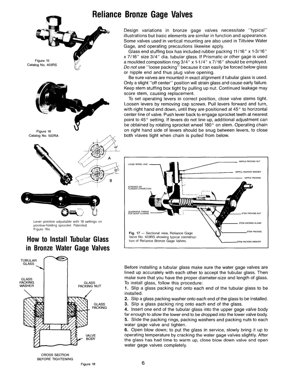
15 Maintenance Instructions for Clark-Reliance Bronze Water Gage Valves Design variations in bronze water gage valves necessitate typical illustrations, but basic elements are similar in function and appearance. Some valves used in vertical mounting are also used in Tiltview Water Gage Valves, and operating precautions likewise apply. Installation When mounting bronze water gage valves, make sure they are mounted in exact alignment, especially when tubular glass is used. Any angular or offset misalignment of the valves will strain the tubular glass and may cause early failure. When installing the armored type gage glass or tubular glass in vertical mounting applications, the overall length of the gage should be 2 ¾ less than the valve centers. With Tiltview applications, please consult drawing number B-7535 to determine the correct gage length. Note that each bronze water gage valve set includes one upper and one lower valve. The lower valve will have a 3/8 FNPT drain connection. The valves must be installed in the correct orientation to ensure proper function. Operating Levers Tools required: ½ wrench To set operating levers in the correct position, close the valve stems tight. Loosen the levers by removing the cap screws. Pull levers forward and turn, with right hand end down, until they are positioned 45 to horizontal centerline of valve. Push the lever back to engage the sprocket teeth at the nearest point to the 45 setting. If the levers do not line up, additional adjustment can be obtained by rotating the sprocket wheel 180 on the valve stem. Operating Chain and Pull Handles Tools required: ¼ wrench, pliers Attach the chain to each side of the upper valve with the S hooks, which are included in the chain package. At this stage the levers should be parallel with each other. Attach the chain on the left side of the valve lever to the S hook on the lower valve. Insert the chain on the right hand side of the lever into the bronze locking fixture. Pull the chain tight between the two valves and tighten the locking screw. This is important in order to obtain full closure of both valves. If there is some slack in the chain on the left side of the valves, it has no adverse effect on the actuation of the valves for opening. Both chains should extend to a safe elevation below the water gage, usually one platform or 10 feet below. Be sure to have water gage valve-operating chains of equal length. Each pull handle comes equipped with S hooks. Insert the free end of each S hook in the bottom link of the correct chain. The handle marked Open is to be installed on the left-hand chain. The handle marked Closed is to be installed on the right-hand chain. Close each hook onto the chain with pliers.
16 Replacing Stem Packing Tools required: 1 ¾ wrench, ½ wrench, ¼ wrench 1) Isolate valves from pressure. 2) Open the drain valve to eliminate any potentially trapped pressure. 3) Unhook operating chains from operating levers. 4) Remove operating handle and sprocket from valve stem. 5) Loosen stem packing nut with 1 ¾ wrench. 6) Turn stem counter-clockwise to remove stem/packing assembly. 7) Remove stem packing nut, packing gland, stem packing, and stem packing washer. Discard old stem packing material. 8) Inspect valve stem and packing cavity in the valve body for steam cut and damage. Replace if necessary. 9) Replace stem packing washer, stem packing (set of three), packing gland (concave side toward stem packing), and stem packing nut. 10) Turn stem/packing assembly into valve body. 11) Thread stem packing nut onto the valve body and tighten with wrench. Ensure that the valve stem, while being tightly sealed, will still open and close. 12) Replace sprocket and operating handle, making sure the handle is properly aligned (see instructions for Operating Levers). 13) Replace operating chain onto operating levers. 14) Slowly open isolation valves and inspect for leakage. Isolate the valve, relieve pressure, and tighten stempacking nut if necessary. Replacing Glass Packing Tools required: 1 ¾ wrench, ½ wrench, ¼ wrench 1) Isolate valves from pressure. 2) Open the drain valve to eliminate any potentially trapped pressure. 3) Unhook operating chains from operating levers. 4) Remove operating handle and sprocket from valve stem. 5) Loosen top and bottom glass packing nuts with 1 ¾ wrench. 6) Remove tubular glass gage or armored gage from valves. 7) Remove nipple/glass packing, glass packing washer, and glass packing nut. Discard old packing material. 8) Inspect the ends and bore of the tubular glass or gage nipples for erosion or steam cutting. Replace any deteriorated or damaged items. 9) To reinstall, slip a glass packing nut onto each end of the tubular glass or ¾ O.D. gage nipple. Follow this with a glass-packing washer and a nipple/glass packing ring. 10) Insert the top of the tubular glass or upper gage nipple into the top valve body. Insert far enough to allow the lower end of the tubular glass or lower gage nipple to be placed into the lower valve body. Slide packing rings, glass packing washers, and glass packing nuts to each valve body and tighten. 11) Replace operating chain onto operating levers. 12) Slowly open isolation valves and inspect for leakage. Isolate the valve, relieve pressure, and tighten glasspacking nut if necessary. NOTE: Always use only genuine Clark-Reliance replacement parts. Any additional questions should be directed to your local Clark-Reliance Representative, Plant-Op Center, or to the Factory (440) The Clark-Reliance Corporation Foltz Industrial Parkway Strongsville, Ohio USA Telephone: (440) Fax: (440) Form E221-A
 with both valves closed and each lever should be positioned at a 45 degree angle downward to the right. See figure #3.")


: 1.")

17 Instructions for Installing Chains on Water Gage Isolation Valve Sets R Section: M100 Bulletin: E-207-A Date: 7/1/01 Supercedes: NEW Installing chains on lever actuated valve set (fig #1) as follows: 1. Adjust levers as illustrated (see fig #1) with both valves closed and each lever should be positioned at a 45 degree angle downward to the right. See figure #3. for instructions to adjust lever onto valve stem. 2. Attach the chain (use #8 size chain) to each side of the upper (steam) valve with the s hooks, which are included in the chain package. At this stage the levers should be parallel with each other. 3. Attach the chain on the left side of the valve lever to the S hook on the lower water valve. Lever Actuated Valves figure #1 4. Insert the chain on the right hand side of the lever into the locking bronze fixture. Pull the chain tight between the two valves and tighten the locking screw. This is important in order to obtain full closure of both valves. If there is some slack in the chain on the left side of the valves, it has no adverse effect on the actuation of the valves for opening. 5. Both chains should extend to a safe elevation below the water gage, usually one platform or 10 feet below. figure #3 Installing chains on chain wheel actuated valve models (fig #2): 1. The chain wheel on the upper (steam) valve extends further from the valve body than the lower (water) valve. This allows the upper valve chain to fall parallel to the lower valve chain without intersecting it. Install a loop of chain around the chain wheel operator, and through the chain guides. 2. Attach ends of chain together (see fig #4). 3. The length of chain for each wheel = the length of drop required times two. 4. Use #1/0 size double loop chain Chain Wheel Actuated Valves figure #2 figure #4 World Leaders in Boiler Level Indication & Control R ISO 9001 registered C O R P O R A T I O N Foltz Industrial Parkway Strongsville, OH 44149, U.S.A. Phone +1(440) Fax +1(440) Clark-Reliance Corp.
Instructions for Installing and Operating Clark Reliance EA100 Series Levalarm
 Section: R500.532F Bulletin: 532F Date: 7/1/2015 Supersedes: 532E Instructions for Installing and Operating Clark Reliance EA100 Series Levalarm This manual covers the following model numbers: EA100D,
Levalarm Gold. Installation, Operation, & Maintenance Instructions R500.E253A 03/16/2016
 Installation, Operation, & Maintenance Instructions R500.E253A 03/16/2016 Levalarm Gold STORAGE AND HANDLING The Reliance Levalarm Gold meets or exceeds all applicable specifications when shipped from
Pressure Relief Valve Maintenance Manual
 Technical Manual 1098T Pressure Relief Valve Maintenance Manual Farris Engineering Division of Curtiss-Wright Flow Control Corporation TABLE OF CONTENTS - Manual Revision 0 Introduction & Safety Tips...
IOM Manual. IOM Manual. Series 76/77.
 IOM Manual IOM Manual Series 76/77 www.flowlinevalves.com Flow Line Valve and Controls, L.L.C. 110 Main Project Road Schriever, LA 70395 P.O. Box 677 Schriever, LA 70395 Phone 985-414-6004 * Toll Free
I & M 8000 Series. Ideal Installation Schematic. Preferred Installation. Trouble Shooting
 I & M 8000 Series 3170 Wasson Road Cincinnati, OH 45209 USA Phone 513-533-5600 Fax 513-871-0105 lowflow@richardsind.com www.lowflowvalve.com Installation & Maintenance Instructions for 8000 Series Low
INSPECTION & MAINTENANCE BULLETIN ARI 1301/1302 1" Plug Type Angle Valves
 INSPECTION & MAINTENANCE BULLETIN ARI 1301/1302 1" Plug Type Angle Valves Item # Description Item # Description 1 Body 12 Washer 2 Packing Retainer 13 Bushing 3 Packet Set 14 Bolt 4 Jam Nut 15 Yoke 5 Stud
HIGH PRESSURE CONTROL VALVE PISTON BALANCED
 PISTON BALANCED All Rights Reserved. All contents of this publication including illustrations are believed to be reliable. And while efforts have been made to ensure their accuracy, they are not to be
Ideal Installation. I & M Mark 67 (1/2 6 ) Control Line. Installation & Maintenance Instructions for Mark 67 Pressure Regulators
 Control Line. Installation & Maintenance Instructions for Mark 67 Pressure Regulators") I & M Mark (/ ) 0 Wasson Road Cincinnati, OH 0 USA Phone --00 Fax -8-00 info@richardsind.com www.jordanvalve.com Installation & Maintenance Instructions for Mark Pressure Regulators Warning: Jordan Valve
I & M Mark (/ ) 0 Wasson Road Cincinnati, OH 0 USA Phone --00 Fax -8-00 info@richardsind.com www.jordanvalve.com Installation & Maintenance Instructions for Mark Pressure Regulators Warning: Jordan Valve
I & M Mark 78 Series. Ideal Installation. Start-Up. Installation & Maintenance Instructions for Mark 78 Control Valves (1-1/2-2 )
") I & M Mark 8 Series 0 Wasson Road Cincinnati, OH 4509 USA Phone 5-5-5600 Fax 5-8-005 info@richardsind.com www.jordanvalve.com Installation & Maintenance Instructions for Mark 8 Control Valves (-/ - ) Warning:
I & M Mark 8 Series 0 Wasson Road Cincinnati, OH 4509 USA Phone 5-5-5600 Fax 5-8-005 info@richardsind.com www.jordanvalve.com Installation & Maintenance Instructions for Mark 8 Control Valves (-/ - ) Warning:
I & M Mark 78 Series. Ideal Installation. Start-Up. Installation & Maintenance Instructions for Mark 78 Control Valves (1/2-1 )
") I & M Mark 8 Series 30 Wasson Road Cincinnati, OH 4509 USA Phone 53-533-5600 Fax 53-8-005 info@richardsind.com www.jordanvalve.com Installation & Maintenance Instructions for Mark 8 Control Valves (/ -
I & M Mark 8 Series 30 Wasson Road Cincinnati, OH 4509 USA Phone 53-533-5600 Fax 53-8-005 info@richardsind.com www.jordanvalve.com Installation & Maintenance Instructions for Mark 8 Control Valves (/ -
PFA LINED BALL VALVES Installation, Operation and Maintenance Manual
 ACRIS PFA LINED BALL VALVES WWW.AMRESIST.COM Table of Contents Safety Instructions - Definition of Terms............................................2 Introduction..............................................................2
Crispin Valves Operating Guide. Crispin
 Crispin Valves Operating Guide Crispin Since 1905 Crispin Multiplex Manufacturing Co. 600 Fowler Avenue Berwick, PA 18603 1-800-AIR-VALV T: (570) 752-4524 F: (570) 752-4962 www.crispinvalve.com sales@crispinvalve.com
DO NOT INSULATE BELOW THIS LINE. * For sizes 1/2" to 1 1/2" add 2 1/2" to 'C' dimension.
 428 Jones Boulevard Limerick Airport Business Center Pottstown, PA 19464 Phone: (610)495-5131 ax: (610)495-5134 www.watsonmcdaniel.com PAGE 28 INSTRUCTION PART NO. 2315400 C.R.3500 REV. 10 SIZE C B CENTER
LOW PRESSURE BALANCED VALVE DIAPHRAGM BALANCED
 DIAPHRAGM BALANCED All Rights Reserved. All contents of this publication including illustrations are believed to be reliable. And while efforts have been made to ensure their accuracy, they are not to
Val-Matic Air / Oil Hydraulic Panel Pump Control System. Operation, Maintenance and Installation Manual
 Manual No. 5AOP-OM1-2 Val-Matic Air / Oil Hydraulic Panel Pump Control System Operation, Maintenance and Installation Manual INTRODUCTION... 1 RECEIVING AND STORAGE... 1 DESCRIPTION OF OPERATION... 1 INSTALLATION...
CV Control Valves Installation and Operation Manual
 CV1500 - Control Valves Installation and Operation Manual 652-EN Overview Warning: This bulletin should be used by experienced personnel as a guide to the installation of the Armstrong CV1500 Control Valve.
PV4 - Compact Shut Off Style Pig Valve IOM - Installation, Operation & Maintenance
 ACECO Valve P.O. Box 9 Mounds, Oklahoma 74047 PV4 - Compact Shut Off Style Pig Valve IOM - Installation, Operation & Maintenance Doc. No.: IOM-PV4-.0 Date: 6/0-00 Revision: A Contents: Installation Operation
Swing-Flex Check Valve
 Manual No. SFCV-OM1-14 Swing-Flex Check Valve Operation, Maintenance and Installation Manual INTRODUCTION.. 1 RECEIVING AND STORAGE. 1 DESCRIPTION OF OPERATION.. 1 INSTALLATION 2 VALVE CONSTRUCTION.. 2
USER INSTRUCTIONS. NAF Trunnball DL Ball Valves. Installation Operation Maintenance. Experience In Motion FCD NFENIM A4 01/15
 USER INSTRUCTIONS NAF Trunnball DL Ball Valves FCD NFENIM4168-01-A4 01/15 Installation Operation Maintenance Experience In Motion Contents SAFETY 3 1 General 3 2 Lifting 4 3 Receiving Inspection 4 4 Installation
Val-Matic 3-72 Cam-Centric Plug Valve
 Manual No. CCPV-OM2-8 Val-Matic 3-72 Cam-Centric Plug Valve Operation, Maintenance and Installation Manual INTRODUCTION... 2 RECEIVING AND STORAGE... 2 DESCRIPTION OF OPERATION... 2 VALVE CONSTRUCTION...
Valtek Flow Boosters
 Valtek Flow Boosters GENERAL INFORMATION This bulletin is designed to assist in installing, adjusting, troubleshooting, and performing maintenance as required for the Valtek Flow Booster. Product users
INSTALLATION, OPERATION AND MAINTENANCE MANUAL (IOM)
") INSTALLATION, OPERATION AND MAINTENANCE MANUAL (IOM) IOM-1088 03-16 Model 1088 Vacu-Gard Blanketing Valve ISO Registered Company SECTION I I. DESCRIPTION AND SCOPE The Model 1088 Vacu-Gard is a tank blanketing
INSTALLATION, OPERATION AND MAINTENANCE MANUAL (IOM) IOM-1088 03-16 Model 1088 Vacu-Gard Blanketing Valve ISO Registered Company SECTION I I. DESCRIPTION AND SCOPE The Model 1088 Vacu-Gard is a tank blanketing
METERING VALVE 2" STEM GUIDED
 2" STEM GUIDED All Rights Reserved. All contents of this publication including illustrations are believed to be reliable. And while efforts have been made to ensure their accuracy, they are not to be construed
KENNEDY VALVE Plant and Industrial Group 1021 East Water Street Elmira, New York Telephone (607) Fax (607)
 Fax (607)") KENNEDY VALVE Plant and Industrial Group 1021 East Water Street Elmira, New York 14901 Telephone (607) 734-2211 Fax (607) 734-3288 INSTALLATION, OPERATION, AND MAINTENANCE MANUAL General ECCENTRIC PLUG
KENNEDY VALVE Plant and Industrial Group 1021 East Water Street Elmira, New York 14901 Telephone (607) 734-2211 Fax (607) 734-3288 INSTALLATION, OPERATION, AND MAINTENANCE MANUAL General ECCENTRIC PLUG
Baumann 24000C Carbon Steel Little Scotty Control Valve Instructions
 Instruction Manual D103356X012 24000C Control Valve Baumann 24000C Carbon Steel Little Scotty Control Valve Instructions CONTENTS Introduction...1 Scope...1 Safety Precautions...1 Maintenance...2 Flow
MAINTENANCE MANUAL FOR THERMOSTATIC TEMPERATURE REGULATING VALVE TRAC STYLE P
 MANUAL NUMBER P-EFS-1 MAINTENANCE MANUAL FOR THERMOSTATIC TEMPERATURE REGULATING VALVE TRAC STYLE P TRAC Regulator Company Inc. 160 South Terrace Avenue Mount Vernon, New York USA 10550-2408 Phone: (914)
CHESTERTON FLOW GUARDIAN S50 AND SP50 SINGLE FLOWMETER INSTALLATION INSTRUCTIONS
 INSTALLATION INSTRUCTIONS CHESTERTON FLOW GUARDIAN S50 AND SP50 SINGLE FLOWMETER INSTALLATION INSTRUCTIONS GENERAL The function of the FLOW GUARDIAN Single S50 (Item # 199801 compression fitting, 199804
Installation and Maintenance Instructions for Grinnell GRP Pneumatic Rack and Pinion Actuators
 FLOW CONTROL for Introduction The Grinnell GRP Pneumatic Actuator is a compact, rack & pinion design, conforming to Grinnell standard or direct mount standards or EN ISO 5211 mounting configuration, depending
NECO Pumping Systems
 INSTALLATION OPERATION & MAINTENANCE INSTRUCTIONS For Your NECO Pumping Systems PACKAGED CIRCULATING SYSTEM THIS COMPLETELY ASSEMBLED, TESTED, PACKAGED CIRCULATING SYSTEM IS OF THE HIGHEST QUALITY AND
Sentinel 250 Fire Hydrant
 Maintenance Instructions manual table of contents PAGE Sentinel 250 Fire Hydrant Inspection and Lubrication 2 Rotating Hydrant to Face Desired Direction 3 Installing Extension Section 3-6 Restoring Service
TECHNICAL DATA CAUTION
 Page 1 of 6 1. DESCRIPTION The Viking Model D-2 Accelerator is a quick-opening device, with an integral anti-flood assembly, used to increase the operating speed of a differential type dry pipe valve.
Installation, Operation and Maintenance Guide II NIBCO High Performance Butterfly Valves Series 6822 and 7822
 Installation, Operation and Maintenance Guide II NIBCO High Performance Butterfly Valves Series 6822 and 7822 Statements: NIBCO High Performance Butterfly Valves, Series 6822 and 7822, have been designed
INSTALL MANUAL. FOR ON LINE ORDERING- E Commerce Visit Our Website
 INSTALL MANUAL FOR ON LINE ORDERING- E Commerce Visit Our Website WWW.PRESSUREGUARD.COM Contact Information Technical Support: Chris@pressureguard.com Sales Support: Sales@pressureguard.com By Phone: 615-227-6024
INSPECTION & MAINTENANCE BULLETIN ARI Plug Type Angle Valves
 INSPECTION & MAINTENANCE BULLETIN ARI 1316 2 Plug Type Angle Valves Item # Description Item # Description Item # Description 1 Body 12 Top Stem Nut 23 Seat Gasket 2 Valve Disc 13 Handwheel 24 Valve Seat
TECHNICAL DATA. Table 1: Model F1 Dry Valve Part Numbers and Specifications
 Page 1 of 11 1. DESCRIPTION The Viking Model F-2 Dry Pipe Valve is a latching differential valve used to separate the water supply from the dry pipe sprinkler system. The valve combines a positive latching
Model DFR 070/156/220 Rotary Actuator
 Figure 1 DFR 156 TABLE OF CONTENTS General 2 Actuator Assembly 18 Scope 2 Bushing / Yoke Assembly 18 Principles of Operation 2 Spring Barrel Assembly 18 Safety Caution 2 Diaphragm Plate Assembly 20 Specifications
Fisher TBX Hydro Plug Fixture
 Instruction Manual TBX Hydro-Plug Fixture Fisher TBX Hydro Plug Fixture Contents Introduction... 1 Scope of Manual... 1 Description... 2 Educational Services... 2 Principle of Operation... 2 Maintenance...
Swing-Flex Check Valve
 Manual No. SFCV-OM1-11 Swing-Flex Check Valve Operation, Maintenance and Installation Manual INTRODUCTION 1 RECEIVING AND STORAGE 1 DESCRIPTION OF OPERATION 1 INSTALLATION 2 VALVE CONSTRUCTION 2 MAINTENANCE
AVK SAUDI VALVES MANUFACTURING COMPANY
 AVK SAUDI VALVES MANUFACTURING COMPANY AVK SERIES 24 - HIGH PRESSURE, WET BARREL HYDRANT FIELD MAINTENANCE AND INSTRUCTION MANUAL TABLE OF CONTENTS EXPLODED ASSEMBLY / PARTS LIST INTRODUCTION / DESCRIPTION
NEECO INDUSTRIES INC. INSTRUCTION MANUAL 7 1/16 10K SLAB GATE BODY
 INSTRUCTION MANUAL 7 1/16 10K SLAB GATE BODY INTRODUCTION The NF-700 type gate valves provided by Neeco Industries are full-bore through conduit non-rising stem manually (w/ball screw) operated valves.
UNIFLO Control Valve
 Severe Service Control Valves MAINTENANCE AND INSTRUCTION MANUAL UNIFLO Control Valve The Problem Solver TM BOTTOM COVER DESIGN DFT INC. 2 www.dft-valves.com DFT INC. 3 www.dft-valves.com WARNING: USER
Installation Instructions
 Installation Instructions Thermostatic Valve and Trim Model No. RH-5944 1 REV.A Restoration Hardware Product Size Specification Diagram General Characteristics In case of instantaneous heaters, hot water
Fisher 1061 Pneumatic Piston Rotary Actuator with Style H & J Mounting Adaptations
 Instruction Manual 1061 H & J Actuator Fisher 1061 Pneumatic Piston Rotary Actuator with Style H & J Mounting Adaptations Contents Introduction... 1 Scope of Manual... 1 Description... 2 Specifications...
Tool-less Hinged Closure Installation, Operation, & Maintenance
 2612 Howard Street Louisville, KY 40211 USA Phone 502-774-6011 Fax 502-774-6300 Website: www.tubeturns.com For genuine Tube Turns Closure parts please contact factory: ttaftermarket@sypris.com Bulletin
CAMSHAFT TIMING CHAIN, SPROCKET, AND TENSIONER REPLACEMENT
 Page 1 of 45 CAMSHAFT TIMING CHAIN, SPROCKET, AND TENSIONER REPLACEMENT Special Tools J 45027 Tensioner Tool J 45059 Angle Meter Page 2 of 45 Removal Procedure Page 3 of 45 Page 4 of 45 Page 5 of 45 Fig.
ONYX VALVE CO MODEL DAC-PFO Installation & Maintenance
 ONYX VALVE CO MODEL DAC-PFO Installation & Maintenance OPERATION: (01-10) The Onyx series DAC-PFO pinch valve fails open on loss of air. This simple spring and air bag arrangement that drives a pair of
for ½" thru 2" 800 lb. Piston Lift Check Valves with Resilient Seat Option
 Manual No. 800-PC Issued: March 31, 2004 INSTRUCTION MANUAL for ½" thru 2" 800 lb. Piston Lift Check Valves with Resilient Seat Option Flowserve Corporation Flow Control Division 1900 S. Saunders Street
1992 Mitsubishi 3000GT VR-4
 TIMING BELT Removal (Diamante SOHC) 1. Remove left front and left side splash shields. Using engine hoist, lift engine just enough to remove weight from engine mounts. Remove drive belts. Remove A/C tensioner
Installation and Maintenance Instructions for Morin MRP Pneumatic Rack and Pinion Actuators
 for Morin MRP Pneumatic Rack and Pinion Actuators Introduction The Morin MRP Pneumatic Actuator is a compact, rack & pinion design, conforming to Keystone standard or direct mount standards or EN ISO 5211
Installation Operation & Maintenance Instructions
 Installation Operation & Maintenance Instructions Contents Please read the installation operation and maintenance instruction prior to using any of our components. Failure to follow the instructions may
LEAD FREE * LFF113RFP Flood Protection Shut Down Valve
 Technical Bulletin TB-ACV-LFF11RFP LEAD FREE * LFF11RFP Flood Protection Shut Down Valve Installed upstream of Reduced Zone Backflow Preventer. Normally Open Valve - Closes when continuous discharge from
CUSTOM COMBINATION AIR VALVE
 INSTALLATION / OPERATION / MAINTENANCE CUSTOM COMBINATION AIR VALVE INTRODUCTION This manual will provide you with the information to properly install and maintain this valve to ensure a long service life.
USER INSTRUCTIONS. Installation Operation Maintenance. NAF Setball SF Ball Sector Valves. Experience In Motion FCD NFENIM A4 09/16
 USER INSTRUCTIONS NAF Setball SF Ball Sector Valves FCD NFENIM4156-00 A4 09/16 Installation Operation Maintenance Experience In Motion Contents SAFETY 3 1 General 3 2 Lifting 4 3 Receiving Inspection 4
26 Series Stainless Steel 2-way Ball Valves
 1-800-899-0553 26 Series Stainless Steel 2-way Ball Valves Users Manual Installation, Operation, & Maintenance 1. General Precaution 1.1. Material Section Material deterioration is determined by the contained
Instructions for Installation, Operation, Care and Maintenance
 Bulletin 407 Rev. T Model E Alarm Check Valve Bulletin 407 Rev. T Instructions for Installation, Operation, Care and Maintenance 4 (100 mm), 6 (150 mm), 8 (200 mm) Sizes With Model E3 Trim Listed by Underwriters
I & M Mark 708. Ideal Installation. Start-Up Procedure. Installation & Maintenance Instructions for Mark 708 & 14M Actuator and Motor Valve
 I & M Mark 708 370 Wasson Road Cincinnati, OH 509 USA Phone 53-533-5600 Fax 53-87-005 info@richardsind.com www.lowflowvalve.com Installation & Maintenance Instructions for Mark 708 & M Actuator and Motor
INSTALLATION INSTRUCTIONS PATIENCE
 INSTALLATION INSTRUCTIONS PATIENCE 706.8X DUAL CONTROL WIDESPREAD LAVATORY FAUCET WITH SPEED CONNECT Thank you for selecting American Standard... the benchmark of fine quality for over 00 years. To ensure
Purging Air From Divider Block Lubrication Systems
 FROST ENGINEERING SERVICE Purging Air From Lubrication Systems A D I V I S I O N O F G E C S E Y S A L E S & S E R V I C E DESCRIPTION Divider block lubrication systems operate correctly only when all
Operating and Maintenance Instructions for: Figure 79 Pneumatic Actuators (U/E options)
") for: Figure 79 Pneumatic Actuators (U/E options) Introduction The Keystone Figure 79 Pneumatic Actuator range is available in three mounting options, as follows:- 79U - Keystone Mounting Standard 79E -
for: Figure 79 Pneumatic Actuators (U/E options) Introduction The Keystone Figure 79 Pneumatic Actuator range is available in three mounting options, as follows:- 79U - Keystone Mounting Standard 79E -
Technical Data SPENCE ENGINEERING COMPANY, INC. 150 COLDENHAM ROAD, WALDEN, NY SD 1520 SERIES 2000 DIRECT & REVERSE ACTING
 Technical Data SD 520 PRINTED IN U.S.A. SD 520/98 SPENCE ENGINEERING COMPANY, INC. 50 COLDENHAM ROAD, WALDEN, NY 2586-205 SERIES 2000 DIRECT & REVERSE ACTING DIRECT & REVERSE ACTING DIMENSIONS inches (mm)
Steam/Water Washdown Units Safety and Operation Installation and Maintenance Instructions
 INSTALLATION AND MAINTENANCE INSTRUCTIONS IM-8-002-US October 2016 Steam/Water Washdown Units Safety and Operation Installation and Maintenance Instructions These instructions should be read by the Company
ONYX VALVE CO MODEL CAR, CAP-PFO Installation & Maintenance
 ONYX VALVE CO MODEL CAR, CAP-PFO Installation & Maintenance OPERATION: (4-2010) The Onyx series CAR-PFO and CAP-PFO pinch valves fail open on loss of air. The simple spring and air bag arrangement drives
Industrial Turbo Meters, Sizes 2" through 6"
 Industrial Turbo Meters Sizes 2" through 6" TUR-UM-00530-EN-19 (October 2014) User Manual Industrial Turbo Meters, Sizes 2" through 6" User Manual CONTENTS Scope of the Manual 5 Specifications 5 Product
Model DF233 Control Valve
 Figure 1 DF233 Control Valve TABLE OF CONTENTS Introduction 2 Body and Packing Reassembly 7 Specifications 3 Fail Closed Actuator Reassembly 8 Valve Sizes 3 Fail Open Actuator Reassembly 9 Unpacking 4
Instructions for Installation, Operation Care and Maintenance
 Model A Dry Pipe Valve Bulletin 353 Rev.K Bulletin 353 Rev.K Instructions for Installation, Operation Care and Maintenance 2 1 2 (65mm) Valve With Model A Trim Listed by Underwriters Laboratories, Inc.
GT-200 GATE VALVES PN16, Screwed end
 Document No. : MD-QO-04-281 Date : 2009/07 /17 Version : 1.0 GT-200 GATE VALVES PN16, Screwed end USER MANUAL Modentic Industrial Corporation 14F-1,No.57Taya Rd.,Taichung,Taiwan,R.O.C. Email:modentic@ms9.hinet.net
KEYSTONE FIGURE 79 PNEUMATIC ACTUATOR OPERATING AND MAINTENANCE INSTRUCTIONS
 Operating and Maintenance Instructions for: Figure 79 Pneumatic Actuators (U/E options) Double Acting Actuator 4. If pipelines are hydraulically tested, then the lines should be blown down with high pressure
Table of Contents Visual Inspection and Neutralizing... 3 Disassembly
 1 Table of Contents Visual Inspection and Neutralizing... 3 Disassembly... 3... 4... 4 Cleaning... 4 Inspection... 4 Reconditioning of Valve Seats... 5 Lapping Procedures... 5 Lapping Blocks... 5 Lapping
I & M Mark 708ME. Ideal Installation. Start-Up Procedure. Installation & Maintenance Instructions for Mark 708 & Motor Actuator
 I & M Mark 708ME 3170 Wasson Road Cincinnati, OH 45209 USA Phone 513-533-5600 Fax 513-871-0105 info@richardsind.com www.lowfl owvalve.com Installation & Maintenance Instructions for Mark 708 & Motor Actuator
Baumann Way Control Valve
 Instruction Manual 24003 Valve Baumann 24003 3-Way Control Valve Contents Introduction... 1 Scope of Manual... 1 Safety Precautions... 2 Educational Services... 3 Maintenance... 3 Installation... 3 Air
Impeller Replacement
 Impeller Replacement Threaded Shaft Frame Mount H 806 Clockwise Rotation Volute shown. 1149 0794 1 Unfasten hardware holding volute to bracket. Remove volute to expose impeller. Peel off old volute gasket
CROSBY SERIES 800 AND 900 OMNI-TRIM PRESSURE RELIEF VALVES INSTALLATION AND MAINTENANCE INSTRUCTIONS
 any and all liability arising out of the same. Any installation, maintenance, adjustment, repair and testing performed on pressure relief valves should be done in accordance with the requirements of all
DYNAFLUID 2000 STEAM & WATER MIXING VALVE INSTALLATION & OPERATING MANUAL
 DYNAFLUID 2000 STEAM & WATER MIXING VALVE INSTALLATION & OPERATING MANUAL LILLY ENGINEERING COMPANY 217 CATALPA STREET P.O. BOX 173 ITASCA, ILLINOIS 60143 630-773-2222 FAX: 630-773-3443 www.lillyengineering.com
Fisher CVX Hydro Plug Fixture
 Instruction Manual CVX Hydro-Plug Fixture Fisher CVX Hydro Plug Fixture Contents Introduction... 1 Scope of Manual... 1 Description... 1 Educational Services... 2 Principle of Operation... 2 Maintenance...
INSTRUCTION MANUAL ACTUATOR CLASSE I TYPE MA, MB
 ACTUATOR CLASSE I TYPE MA, MB CONTENTS Page : 2/13 PRODUCT DESCRIPTION General description 3 Product specification 5 INSTALLATION Storage 6 Unpacking 7 Handling 7 Installation : Mechanical 7 Installation
Technical Manual MSI Hydraulic Adjustable Choke
 Technical Manual MSI Hydraulic Adjustable Choke MSI A Division of Dixie Iron Works, Ltd. 300 W. Main St. Alice, TX 78332 www.diwmsi.com (800) 242-0059 Revision A TABLE OF CONTENTS SECTION 1 WARNINGS...
MEMORY SEAL BALL VALVES MAINTENANCE MANUAL 2 12, Class 150 & 300, Regular Port, Flanged Unibody
 MEMORY SEAL BALL VALVES MAINTENANCE MANUAL 2 12, Class 150 & 300, Regular Port, Flanged Unibody I INTRODUCTION These rugged, versatile, high performance, regular port, ball valves meet all requirements
FRP Ball Valves INSTALLATION & MAINTENANCE MANUAL
 FRP Ball Valves INSTALLATION & MAINTENANCE MANUAL FRP BALL VALVES TABLE OF CONTENTS MAINTENANCE AND INSTALLATION INSTRUCTIONS 1. 2. 2.1 2.2 2.3 2.4 GENERAL...Page 1 HANDLING...1 Receiving and Storing...1
OSYSU Series Outside Screw and Yoke Valve Supervisory Switch
 Features NEMA 4X* (IP 65) and 6P (IP 67) *Enclosure is 4X. For additional corrosion protection of mounting hardware, use model OSYSU-2 CRH -40º to 140º (-40ºC to 60ºC) operating temperature range Visual
EDGEMERE DUAL CONTROL WIDESPREAD LAVATORY FAUCET INSTALLATION INSTRUCTIONS
 EDGEMERE DUAL CONTROL WIDESPREAD LAVATORY FAUCET INSTALLATION INSTRUCTIONS 708.80 Thank you for selecting American Standard... the benchmark of fine quality for over 00 years. To ensure that your installation
M-5000TG/5700TG Steam and Cold Water Mixing Unit
 M-5000TG/5700TG Steam and Cold Water Mixing Unit Installation, Operating and Maintenance Instructions Last Updated: October, 2012 Strahman Valves, Inc. USA Headquarters 2801 Baglyos Circle Bethlehem, PA
Installation, Operation and Maintenance Instructions Series 608 Ball Valve
 b. With valve open, remove three body bolts, loosen fourth and swing out body. Remove fourth bolt and spread pipe ends Close valve, remove ball, seats, body seals. Return body to its original position
SERIES PC INSTRUCTION AND OPERATION MANUAL
 MEGGA SERIES PC INSTRUCTION AND OPERATION MANUAL Models PCT and PCF Close-coupled and frame-mounted single-stage horizontal end-suction pumps. WARNING: Read this manual before installing or operating this
STERILMATIC DIGITAL ELECTRIC STERILIZER PARTS AND SERVICE MANUAL
 STERILMATIC DIGITAL ELECTRIC STERILIZER PARTS AND SERVICE MANUAL EFFECTIVE JULY 19, 2017 Superseding All Previous Parts Lists. The Company reserves the right to make substitution in the event that items
W91/W94 Series TEMPERATURE REGULATORS. Self-Operated Temperature Regulators. Design & Operation W91 Non-Indicating W94 Dial Thermometer
 Design & Operation W91 Non-Indicating W94 Dial Thermometer Watson McDaniel reserves the right to change the designs and/or materials of its products without notice. 2010 Watson McDaniel Company CAPILLARY
OWI 35C-7/ 35C-7H PIPE SPINNER
 OWI 35C-7/ 35C-7H PIPE SPINNER OIL WORKS, INC.. manufactures the OWI 35C-7 pipe spinner in Pneumatic and Hydraulic Versions at our facility in Odessa, TX. We offer new and rebuilt units, and stock a full
M-5000TG/5700TG Steam and Cold Water Mixing Unit
 M-5000TG/5700TG Steam and Cold Water Mixing Unit Installation, Operating and Maintenance Instructions Last Updated: August, 2014 Strahman Valves, Inc. USA Headquarters 2801 Baglyos Circle Bethlehem, PA
CONTROL VALVES SINGLE PORTED CLASSES DL, DDL, DOS, DDOS
 12501 Telecom Drive, Tampa Florida 33637 Installation, Operation and Maintenance 10/1.5.1 Rev. 0 CONTROL VALVES SINGLE PORTED CLASSES DL, DDL, DOS, DDOS TABLE OF CONTENTS INSTALLATION...2 VALVE POSITION...2
Ideal Installation. I & M Mark 80. Bulb Installation PROTECT VALVES WITH LINE STRAINERS
 I & M Mark 80 370 Wasson Road Cincinnati, OH 4509 USA Phone 53-533-5600 Fax 53-87-005 info@richardsind.com www.jordanvalve.com Installation & Maintenance Instructions for Mark 80 Temperature Regulator
Installation, Operation & Maintenance Manual. Bulletin: IOMS-PUL CHEMAlarm LEAK DETECTIONI
 Installation, Operation & Maintenance Manual Bulletin: IOMS-PUL-1011 CHEMAlarm LEAK DETECTIONI 1 TABLE OF CONTENTS 1. PRINCIPLES OF OPERATION... 3 1.1 General Description... 3 1.2 Process Specifications...
PRESSURE REGULATOR BACK PRESSURE TO ATMOSPHERE WITH OUTSIDE SUPPLY
 PRESSURE REGULATOR BACK PRESSURE TO ATMOSPHERE WITH OUTSIDE SUPPLY All Rights Reserved. All contents of this publication including illustrations are believed to be reliable. And while efforts have been
INSTALLATION INSTRUCTIONS
 INSTALLATION INSTRUCTIONS MODEL: LUGARNO 23580075 (RH-5910) 23580134 (RH-5910L) 1 REV C Restoration Hardware Faucet Product Size Specification Diagram Dimensions are in Inches and Approximation of a Typical
Model AD-29A Automatic Air Spray Gun and Can Marking System
 Model AD-29A Automatic Air Spray Gun and Can Marking System Part 07 979A NORDSON CORPORATION. AMHERST, OHIO. USA 2-454d TECHNICAL PUBLICATION Nordson Corporation Finishing Equipment Division ISSUED 4/85
THD-SERIES S11DA280 THRU S27DA1020 & S11SR280 THRU S27SR1020 DOUBLE ACTING & SPRING RETURN SCOTCH YOKE ACTUATORS
 THD-SERIES S11DA280 THRU S27DA1020 & S11SR280 THRU S27SR1020 DOUBLE ACTING & SPRING RETURN SCOTCH YOKE ACTUATORS INTRODUCTION A-T Controls THD scotch yoke actuators have been designed and engineered to
I & M MK96 & MK96C. Ideal Installation. Start-Up. Maintenance PROTECT VALVES WITH LINE STRAINERS
 **VIP** If you purchased your MK96 or MK96C Valve, or any stem repair component for this valve, after 9/7/08 - please see **VIP** assembly instruction change on page, middle-right, section. I & M MK96
INSTALLATION, OPERATION, MAINTENANCE MANUAL FOR MANUALLY OPERATED STOP CHECK VALVE
 INSTALLATION, OPERATION, MAINTENANCE MANUAL FOR MANUALLY OPERATED STOP CHECK VALVE Page 1 of 13 1.1 General CHAPTER 1 - GENERAL INFORMATION This manual contains maintenance instructions with pertinent
Ideal Installation. I & M Mark 80. Bulb Installation PROTECT VALVES WITH LINE STRAINERS
 I & M Mark 80 370 Wasson Road Cincinnati, OH 4509 USA Phone 53-533-5600 Fax 53-87-005 info@richardsind.com www.jordanvalve.com Installation & Maintenance Instructions for Mark 80 Temperature Regulator
Part # Regulator Rebuild Kit for SuperFlow and SuperFlow 350 Regulators
 Part #525-309 Regulator Rebuild Kit for SuperFlow and SuperFlow 350 Regulators Tools Required Part Number Description Qty 510-011 O-ring 1 510-014 O-ring 1 510-552 Exhaust Valve 1 510-553 Diaphragm 1 520-032
An Illustrated Manual: Constant Level Lubricators Function, Installation, and Features
 An Illustrated Manual: Constant Level Lubricators Function, Installation, and Features Constant Level Lubricators Table of Contents Overview Typical Applications and Industries..........................
LEAD FREE * LFF113RFP Wireless Smart Flood Protection Shut Down Valve with SentryPlus Alert Technology
 Technical Bulletin TB-ACV-LFF11RFP_SentryPlus LEAD FREE * LFF11RFP Wireless Smart Flood Protection Shut Down Valve with SentryPlus Alert Technology Installed upstream of Reduced Zone Backflow Preventer.