Reasons for reissue of this instruction sheet are provided in Section 8, REVISION SUMMARY.
|
|
|
- Sharyl Cunningham
- 5 years ago
- Views:
Transcription
1 Reasons for reissue of this instruction sheet are provided in Section 8, REVISION SUMMARY. The simplex connector kit consists of a connector assembly, short boot, and tubing. The tubing is used with 250 m coated fiber. Also included, assembled onto the connector, are a termination cover for the ferrule (front of connector) and a protective cap for the plunger (rear of connector). The duplex connector kit consists of two of each of these components and a duplex clip. The duplex clip is also available separately. Figure 1 LightCrimp Plus LC simplex and duplex fiber optic connector kits are designed to be applied to fiber optic cable. The connectors are used with singlemode or multimode 125 m glass fiber cable. These kits can be used with any of the following media (paragraph of assembly procedure is indicated next to media). Read these instructions thoroughly before assembling the connector kit. Micro Strip Stripper Combination Strip Tool Cable Holder Assembly or (only used to terminate connector with termination cover installed)
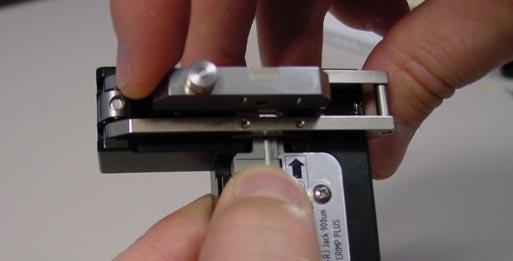
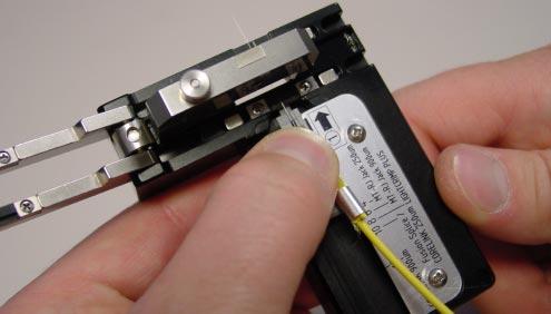
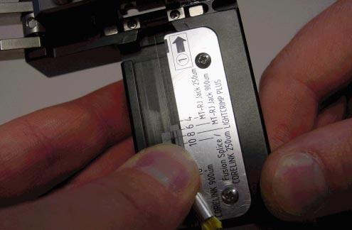
2 Fiber Optic Cleaver (Instruction Sheet ) LightCrimp Plus LC Die Set with Crimping Tool (consists of Die Set and PRO CRIMPER* III Hand Tool ) or LightCrimp Plus LC, SC, and Splice Die Set with Crimping Tool (consists of Die Set and LightCrimp Termination Handle Microscope Kit mm Universal Microscope Adapter reagent grade isopropyl alcohol and lint free cloths (not included) Alcohol Fiber Wipe Packet Discard the tubing. 2. Slide the short boot (small diameter end first) over the buffer. See Figure 2, Detail A. 3. Remove the rear protective cap from the connector assembly, and discard. 4. Push the connector assembly into the holder of the cable holder assembly with the termination cover facing outward, making sure that the connector butts against the lip on the arm of the cable holder assembly. See Figure 2, Detail B. 5. Slide the buffer into the channel marked BUFFER. Make sure that the tip of the buffer butts against the end of the channel. Mark the fiber at each cross slot of the channel. See Figure 2, Detail B. Then, remove the fiber from the cable holder assembly. For easy strip buffered fiber, using the strip tool, notch the fiber at the first mark. Then, grasp the cut end of the fiber and, using a gentle pulling motion, remove the buffer. If using the stripper, notch the fiber at the first mark, then pull the buffer off with the stripper. Strip the coating to the end of the buffer with a single pass of the tool. If the coating slides out relative to the buffer, carefully push it back to the original position (flush with the buffer). See Figure 2, Detail C. For tight buffered fiber, using the strip tool or stripper, strip the fiber to the first mark. It is recommended stripping the fiber in three sections. See Figure 2, Detail C. 6. Clean the fiber with isopropyl alcohol and a lint free cloth to remove the fiber coating residue. 1. Open the fiber clamp of the fiber optic cleaver. Press the button, and slide the carriage back (toward the fiber clamp). Then move the fiber slide back until it stops. 2. Place the stripped fiber into the slot so that the end of the buffer is at the 8 mm marking. See Figure 3, Detail A. 3. While applying pressure on the buffer, carefully slide the fiber slide forward (toward the carriage) until it stops. See Figure 3, Detail B. 4. Gently close the fiber clamp, and slide the carriage forward. DO NOT touch the button while sliding the carriage. See Figure 3, Detail C. 5. Open the fiber clamp, and move the fiber slide back until it stops. 6. Remove the cleaved fiber, and properly dispose of the scrap fiber. 1. Open the cable clamp of the cable holder assembly, and position the fiber (with the cleaved end facing the connector) inside the clamp. Move the buffer so that the end of the fiber is even with the front of the arm of the cable holder assembly, and holding the buffer in place, close the clamp. See Figure 4, Detail A. 2. Carefully insert the fiber into the plunger of the connector assembly until the fiber bottoms against the internal fiber. Make sure that the remaining mark on the buffer enters the plunger. The resultant bend in the fiber should hold the fiber against the internal fiber. See Figure 4, Detail B.
3 3. Squeeze the handles of the hand tool until the ratchet releases. Allow the handles to open fully. Slowly close the handles until you hear 3 clicks from the ratchet. b. Using a biasing force, push the connector into the opening until there is an audible click. DO NOT force the connector onto the duplex clip. c. Center the channel B connector between the duplex clip opening marked B with the recess in the connector aligned with the rib of the duplex clip. Make sure that the termination cover (of the connector) is pointing in the direction of the arrow on the duplex clip. d. Repeat Step b. 4. With the connector assembly in the cable holder assembly, position the termination cover in the upper cavity of the front die and the plunger in the upper cavity of the rear die. See Figure 4, Detail C. If connecting connectors, remove the termination cover, and inspect the ferrule end face for cleanliness using microscope kit and 1.25 mm universal adapter. 5. Gently push the buffer toward the connector assembly to make sure that the fiber is still bottomed, then slowly squeeze the tool handles together with both hands until the ratchet releases. Allow the handles to open fully, and remove the connector from the dies. 6. Position the plunger of the connector assembly in the cavity of the front die with the knurl against the edge of the groove in the die and the termination cover pointing in the direction of the arrow. See Figure 5, Detail A. 7. Slowly squeeze the tool handles together until the ratchet releases. Allow the handles to open fully, and remove the connector assembly from the die. 8. Open the cable clamp of the cable holder assembly, and remove the fiber from the clamp. Slide the short boot over the plunger until it butts against the connector assembly. See Figure 5, Detail B. 9. Remove the connector assembly from the cable holder assembly. 10. For the duplex connector kit, refer to Figure 5, Detail C, and install the duplex clip as follows: a. Center the channel A connector between the duplex clip opening marked A with the recess in the connector aligned with the rib of the duplex clip. Make sure that the termination cover (of the connector) is pointing in the direction of the arrow on the duplex clip. Professional Fiber Optic Connector Inspection Kit [ ] (Instruction Sheet ) Fiber Optic Cleaning and Inspection Guide (on compact disc) More information can be found at
4
5
6 6. Remove the cleaved fiber, and properly dispose of the scrap fiber. 1. Slide the short boot (small diameter end first) over the fiber. See Figure 2, Detail A. 2. Remove the rear protective cap from the connector assembly, and discard. 3. Insert the tubing into the plunger of the connector assembly until the tubing bottoms. See Figure 2, Detail A. 4. Push the connector assembly into the holder of the cable holder assembly with the termination cover facing outward, making sure that the connector butts against the lip on the arm of the cable holder assembly. See Figure 2, Detail B. 5. Slide the fiber into the channel marked BUFFER. Make sure that the tip of the fiber butts against the end of the channel. Make sure that the tubing does not fall out of the connector assembly. Mark the fiber at each cross slot of the channel. See Figure 2, Detail B. Then, remove the fiber from the cable holder assembly. 6. Using the strip tool or stripper, strip the fiber to the first mark using a single pass. See Figure 2, Detail C. 7. Clean the fiber with isopropyl alcohol and a lint free cloth to remove any coating residue. 1. Open the fiber clamp of the fiber optic cleaver. Press the button, and slide the carriage back (toward the fiber clamp). Then move the fiber slide back until it stops. 2. Place the stripped fiber into the slot so that the end of the coating is at the 8 mm marking. See Figure 3, Detail A. 3. While applying pressure on the fiber, carefully slide the fiber slide forward (toward the carriage) until it stops. See Figure 3, Detail B. 4. Gently close the fiber clamp, and slide the carriage forward. DO NOT touch the button while sliding the carriage. See Figure 3, Detail C. 5. Open the fiber clamp, and move the fiber slide back until it stops. 1. Open the cable clamp of the cable holder assembly, and position the fiber (with the cleaved end facing the connector) inside the clamp. Move the fiber so that the end of the stripped fiber is even with the front of the arm of the cable holder assembly, and holding the fiber in place, close the clamp. See Figure 4, Detail A. 2. Carefully insert the fiber into the plunger of the connector assembly until the fiber bottoms against the internal fiber. The fiber coating must enter the small tubing that was installed in Step 3 of Paragraph 5.1.A. Make sure that the start of the fiber coating is not caught on the entry of the small tubing. and that the remaining mark on the fiber enters the plunger. The resultant bend in the fiber should hold the fiber against the internal fiber. See Figure 4, Detail B. 3. Squeeze the handles of the hand tool until the ratchet releases. Allow the handles to open fully. Slowly close the handles until you hear 3 clicks from the ratchet. 4. With the connector assembly in the cable holder assembly, position the termination cover in the upper cavity of the front die and the plunger in the upper cavity of the rear die. See Figure 4, Detail C. 5. Gently push the fiber toward the connector assembly to make sure that the fiber is still bottomed, then slowly squeeze the tool handles together with both hands until the ratchet releases. Allow the handles to open fully, and remove the connector from the dies.
7 6. Position the plunger of the connector assembly in the cavity of the front die with the knurl against the edge of the groove in the die and the termination cover pointing in the direction of the arrow. See Figure 5, Detail A. 7. Slowly squeeze the tool handles together until the ratchet releases. Allow the handles to open fully, and remove the connector assembly from the die. 8. Open the cable clamp of the cable holder assembly, and remove the fiber from the clamp. Slide the short boot over the plunger until it butts against the connector assembly. See Figure 5, Detail B. 9. Remove the connector assembly from the cable holder assembly. 10. For the duplex connector kit, refer to Figure 5, Detail C, and install the duplex clip as follows: a. Center the channel A connector between the duplex clip opening marked A with the recess in the connector aligned with the rib of the duplex clip. Make sure that the termination cover (of the connector) is pointing in the direction of the arrow on the duplex clip. b. Using a biasing force, push the connector into the opening until there is an audible click. DO NOT force the connector onto the duplex clip. c. Center the channel B connector between the duplex clip opening marked B with the recess in the connector aligned with the rib of the duplex clip. Make sure that the termination cover (of the connector) is pointing in the direction of the arrow on the duplex clip. d. Repeat Step b. Professional Fiber Optic Connector Inspection Kit [ ] (Instruction Sheet ) Fiber Optic Cleaning and Inspection Guide (on compact disc) More information can be found at Following this procedure should prevent damage to the duplex clip and allow reuse of the duplex clip. 1. Using one hand, hold the assembly by either the connector that will not be removed or the duplex clip. 2. With the other hand, grasp the connector to be removed and, using a rotation motion, gently remove the connector from the opening. Refer to Figure 6. If connecting connectors, remove the termination cover, and inspect the ferrule end face for cleanliness using microscope kit and 1.25 mm universal adapter. Figure 6
8 Revisions to this instruction sheet include: Updated document to corporate requirements Added Stop! banner to page 1 Removed connector kit part numbers and duplex clip part number Added multimode cable and changed description for use of tubing Modified Figures 1, 2 (Details A and B), 3, 4, 5, and 6 Added Detail C to Figure 2 Changed ferrule dust cap to termination cover Changed combination strip tool, cleave tool, die set, hand tool frame assembly, microscope, microscope adapter, and LC termination kit; added cable holder assembly; and removed combination termination kit Modified Step 2 of Paragraph 5.1, A and Steps 2 and 6 of 5.2, A Removed CAUTION from Paragraphs 5.1, B and 5.2, B Changed 1 click to 3 clicks in Step 3 of Paragraph 5.1, C and 5.2, C Changed receptacle to holder in Step 4 of Paragraphs 5.1, A and 5.2, A Deleted Paragraph 5.1, A.6 Deleted stripper in 5.1,A.5 CAUTION Added new text to second paragraph 5.1,A.5 Added text to Paragraph 5.1,A.6 Modified Paragraph 5.1, B, 5.2, B; and 5.2, C.1 and 2 Added inspection pointer to Paragraphs 5.1 and 5.2 Removed smallest from Step 6 of Paragraph 5.1, C Added with both hands to Paragraph 5.1, C.5 Changed fiber to buffer in Paragraph 5.1,C Removed previous Section 7 Added Cleaning Flow Matrix to page 8 Added reference to inspection kit and cleaning and inspection guide Moved end STOP artwork and available aids to Paragraphs 5.1, C.10.d and 5.2, C.10.d Moved Figures 2, 3, 4, and 5 to middle of document
Instruction Sheet Simplex and Duplex. LightCrimp Plus LC. Fiber Optic Connector Kits Feb 2017 Rev E
 LightCrimp Plus LC Instruction Sheet Simplex and Duplex 408-8925 Fiber Optic Connector Kits Feb 2017 Rev Reasons for reissue of this instruction sheet are provided in Section 8, RVISION SUMMARY. The simplex
3M No Polish Connector 8800-APC/AS SM SC/APC, Angle Splice, 250/900-µm. Instructions. October C
 3M No Polish Connector 8800-APC/AS SM SC/APC, Angle Splice, 250/900-µm Instructions October 2010 78-8140-1581-0-C Contents 1.0 Summary...3 2.0 Connector Preparation...4 3.0 Fiber Preparation...4 4.0 Fiber
3M No Polish LC/APC Connector SM, Angle Splice, 250/900 µm 8830-APC/AS
 3M No Polish LC/APC Connector SM, Angle Splice, 250/900 µm 8830-APC/AS Instructions January 2009 78-8140-3691-5-A Contents 1.0 Summary...3 2.0 Connector Preparation...4 3.0 Fiber Preparation...4 4.0 Fiber
Instruction Sheet 39mm Patch Panel MT RJ Jack Kits [ ], [ ], and [ ]
![Instruction Sheet 39mm Patch Panel MT RJ Jack Kits [ ], [ ], and [ ]](/thumbs/90/102398289.jpg "Instruction Sheet 39mm Patch Panel MT RJ Jack Kits [ ], [ ], and [ ]") Instruction Sheet 39mm Patch Panel MT RJ Jack Kits 1278303 [ ], 1278807 [ ], and 1278808 [ ] 20 OCT 03 250 m Fiber Guide Icon Wheel ctuation Key (2 Included) The jacks can also be installed in wall outlets
Instruction Sheet 39mm Patch Panel MT RJ Jack Kits 1278303 [ ], 1278807 [ ], and 1278808 [ ] 20 OCT 03 250 m Fiber Guide Icon Wheel ctuation Key (2 Included) The jacks can also be installed in wall outlets
3M No Polish Connector 8800-APC/AS SM SC/APC, Angle Splice, 250/900 µm Instructions
 3M No Polish Connector 8800-APC/AS SM SC/APC, Angle Splice, 250/900 µm Instructions February 2008 78-8140-1581-0 Contents 1.0 Summary...3 2.0 Connector Preparation...4 3.0 Fiber Preparation...4 4.0 Fiber
3M No Polish LC Connector SM and MM, Flat Splice, 250/900 µm
 3M No Polish LC Connector SM and MM, Flat Splice, 250/900 µm Instructions January 2009 78-8140-3696-4-A 3 Contents 1.0 Kit Contents... 3 2.0 3M No Polish LC Connector SM & MM 250/900 µm... 4 Safety Precautions
Crimp & Cleave Termination Instructions
 Your Optical Fiber Solutions Partner Crimp & Cleave Termination Instructions for 50 and 62.5µm GiHCS, 200µm HCS SC and SC-RJ Connectors For Use With: 50 and 62.5µm GiHCS 2.5mm Aramid Reinforced Optical
FIBER CONNECTOR SAFETY WARNINGS
 FIBER CONNECTOR SAFETY WARNINGS SAFETY INFORMATION 1. Always wear safety glasses. 2. Isopropyl alcohol is flammable and may cause eye irritation. In case of contact with eyes, flush with water for at least
Crimp & Cleave Termination Instructions
 Your Optical Fiber Solutions Partner Crimp & Cleave Termination Instructions for 50 and 62.5 µm GiHCS, 200 µm HCS LC Connectors For Use With: 50 and 62.5 µm GiHCS 2.2 mm Fiber Optic Cables 200 µm HCS 2.2
OFS Assembly Instructions Instruction Sheet for LC Comcode: Fiber Optic Behind-The-Wall (BTW) Connectors
 Connectors") OFS Assembly Instructions 640-252-053 Instruction Sheet for LC Comcode: 847 953 205 Fiber Optic Behind-The-Wall (BTW) Connectors Epoxy and EZ Methods Singlemode and Multimode Versions Connector Components
OFS Assembly Instructions 640-252-053 Instruction Sheet for LC Comcode: 847 953 205 Fiber Optic Behind-The-Wall (BTW) Connectors Epoxy and EZ Methods Singlemode and Multimode Versions Connector Components
Instructions for Use - Opt-X Ultra Enclosure Directives Enceintes Opt-X Ultra MC Instrucciones de Uso Caja Opt-X Ultra MR
 5R1UH-S03 5R2UH-S06 5R4UH-S12 Instructions for Use - Opt-X Ultra Enclosure Directives Enceintes Opt-X Ultra MC Instrucciones de Uso Caja Opt-X Ultra MR 5R1UH-S03 5R2UH-S06 5R4UH-S12 Page 1 of 26 Leviton
JUL 17 Rev M
 Hand Crimping Tool and Cable Preparation Kit; PN 59981-1 Instruction Sheet 408-6788 24 JUL 17 Rev M PROPER USE GUIDELINES Cumulative Trauma Disorders can result from the prolonged use of manually powered
No. Tool Vendor P/N. Furukawa FITEL Furukawa FITEL Furukawa FITEL Furukawa FITEL Furukawa FITEL Furukawa FITEL Furukawa FITEL.
 TOUCH Plus SC Splice-On Connector for Cordage Standard assembly procedure of TOUCH Plus SC Splice-On Connector is as below. Caution : Wear eye protection glasses when handling optical fibers. 1. Preparation
Instructions for Use - Opt-X 1000i Enclosure
 5R1UM-F03, 5R1UM-S03, 5R2UM-F06, 5R2UM-S06, 5R3UM-F09, 5R3UM-F12, 5R4UM-F12, 5R4UM-F15 Instructions for Use - Opt-X 1000i Enclosure 5R1UM-*03 5R2UM-*06 5R3UM-F** 5R4UM-F** Page 1 of 8 Leviton Network Solutions,
2. Use Extraction Tool (contact extraction tool). Insert releasing tip into the REAR of the. cavity between the spring and center wall of the
. Insert releasing tip into the REAR of the. cavity between the spring and center wall of the") Twin Leaf PC Board Edge Connectors are designed for wire to pc board applications. To meet specific circuit requirements, housings are supplied (1) to be assembled using contacts, retaining springs, and
Twin Leaf PC Board Edge Connectors are designed for wire to pc board applications. To meet specific circuit requirements, housings are supplied (1) to be assembled using contacts, retaining springs, and
Heavy Duty Miniature Quick-Change Applicator (End-Feed Type) with Mechanical or Air-Feed Systems
 with Mechanical or Air-Feed Systems") Heavy Duty Miniature Quick-Change Applicator (End-Feed Type) with Mechanical or Air-Feed Systems Instruction Sheet 408-8039 02 JUN 16 Rev G Ram Post Wire Disc Insulation Disc Insulation Crimper Stripper
Heavy Duty Miniature Quick-Change Applicator (End-Feed Type) with Mechanical or Air-Feed Systems Instruction Sheet 408-8039 02 JUN 16 Rev G Ram Post Wire Disc Insulation Disc Insulation Crimper Stripper
HARD TRI-FOLD COVER SPECIAL BOLT ON SIDE RAIL INSTRUCTIONS 2016-ON TOYOTA TACOMA 6 BOX
 HARD TRI-FOLD COVER SPECIAL BOLT ON SIDE RAIL INSTRUCTIONS 2016-ON TOYOTA TACOMA 6 BOX Read and follow these special instructions along with the standard instructions carefully before installing or using
Tooling Assistance Center
 Safeguards are designed into this application equipment to protect operators and maintenance personnel from most hazards during equipment operation. However, certain safety precautions must be taken by
MX150L ASSEMBLY INSTRUCTIONS
 CONNECTOR PLUG ASSEMLY TERMINAL INSERTION MX150L ASSEMLY INSTRUCTIONS 1. egin assembly of the crimped male terminals into the plug housing by making sure the Terminal Position Assurance feature () is in
Heavy Duty Miniature Quick-Change Applicator (Side-Feed Type) with Mechanical or Air Feed Systems
 with Mechanical or Air Feed Systems") Heavy Duty Miniature Quick-Change Applicator (Side-Feed Type) with Mechanical or Air Feed Systems Instruction Sheet 408-8040 30 NOV 17 Rev H Ram Assembly Ram Post Locking Screw Stock Drag Drag Release
Heavy Duty Miniature Quick-Change Applicator (Side-Feed Type) with Mechanical or Air Feed Systems Instruction Sheet 408-8040 30 NOV 17 Rev H Ram Assembly Ram Post Locking Screw Stock Drag Drag Release
INSTALLATION INSTRUCTIONS South Highway 11 Westminster, SC Toll Free (888) (864) FAX (864)
 (864) FAX (864)") 1.0 Purpose: To identify requirements for the replacement of ISS seals, o-ring and installation of gland nut to rod. 2.0 Scope: This instruction applies to the ISS units manufactured at Lift Technologies
1.0 Purpose: To identify requirements for the replacement of ISS seals, o-ring and installation of gland nut to rod. 2.0 Scope: This instruction applies to the ISS units manufactured at Lift Technologies
HARD TRI-FOLD COVER SPECIAL BOLT ON SIDE RAIL INSTRUCTIONS 2016-ON TOYOTA TACOMA 5 BOX
 HARD TRI-FOLD COVER SPECIAL BOLT ON SIDE RAIL INSTRUCTIONS 2016-ON TOYOTA TACOMA 5 BOX Read and follow these special instructions along with the standard instructions carefully before installing or using
FiberConnect Bare Fiber Adapter. nrit
 Operating Instructions 41820B FiberConnect Bare Fiber Adapter nrit http://www.anritsu.com 2006 Anritsu Instruments Company. All rights reserved. This document and the product-towhidrit relatesare~rotectetfby
MAR 11 Rev H
 SDE Battery Powered Crimp Tool Kit 1725837- [ ] Customer Manual 409-10053 23 MAR 11 Rev H SAFETY PRES READ THIS FIRST!... 2 1. INTRODUCTION... 5 2. RECEIVING/INSPECTION... 5 3. INSTALLATION/REMOVAL OF
LC Cable Assemblies. Fiber Optic Products Catalog. Product Facts. LC Cable Assembly. Hybrid LC-SC Cable Assembly
 LC Cable Assemblies Product Facts For high performance applications/high density 125 µm Ceramic Ferrule Technology Small size 1/2 size of standard SC and FC products Singlemode and multimode Tuned singlemode
StepWave ion guide: cleaning instructions addendum
 StepWave ion guide: cleaning instructions addendum StepWave ion guide: cleaning instructions addendum This document, an addendum to the following documents, describes an improved cleaning procedure for
CORNING. CamSplice User Guide 2. TOOLS AN MATERIALS 1. GENERAL 3. LOADING CAMSPUCE INTO TOOL
 CORNING CamSplice User Guide pin 006-038, Issue 13 1. GENERAL This procedure outlines the use of the Cam Splice and TKT-1 00-01 and TKT-100-02 tool kit for splicing optical fibers (see Table 1). This document
Maintenance Adjustments
 4 Maintenance and Adjustments Chapter Contents Cleaning the Printer and Paper Handling Accessories..... 158 Cleaning the HP Digital Copier....................... 161 Cleaning ADF and Glass............................
JAN 18 Rev E
 PIDG* PEEK STRATO-THERM* Terminal Crimping Dies Instruction Sheet 408-10039 16 JAN 18 Rev E PROPER USE GUIDELINES Cumulative Trauma Disorders can result from the prolonged use of manually powered hand
Volition. VF-45 Quick Install kit. and Maintenance Cleaning Kit. 3Innovation
 Volition VF-45 Quick Install Kit and Maintenance Cleaning Kit O b D s oc ol e um te en t COOL HAND TOOLS. VF-45 Quick Install kit Get your hands on a VF-45 Quick Install Kit from 3M and you will have everything
Splicing Procedures 4. 2 Insert the new wire between the parted strands. If more than one wire is being spliced, wrap them in opposite directions. Use
 Splicing Procedures 1 Splicing Procedures Refer to applicable wiring diagrams for circuit information. This procedure contains multiple splicing techniques. Review splicing procedures prior to performing
AUG 18 Rev M
 ORIGINAL INSTRUCTIONS 626 Pneumatic Tooling Assemblies 189721-[ ] and 189722-[ ] Customer Manual 409-5862 06 AUG 18 Rev M SAFETY PRECAUTIONS AVOID INJURY READ THIS FIRST!... 2 1. INTRODUCTION... 4 2. DESCRIPTION...
AMPSEAL 16* Connector System 24 JUN 13 Rev C
 Application Specification 114-13065 AMPSEAL 16* Connector System 24 JUN 13 i All numerical values are in metric units [with U.S. customary units in brackets]. Dimensions are in millimeters [and inches].
NUMBER: S.M. REF.: Refer to 2.5 ENGINE: 60 DATE: January 2007
 NUMBER: 1 60 07 S.M. REF.: Refer to 2.5 ENGINE: 60 DATE: January 2007 SUBJECT: N3 ELECTRONIC INJECTOR PUBLICATION: 6SE483 The Series 60 Service Manual has been revised. Engine models built from December
Environmental Distribution Center (EDC-06P-NH)
") Corning Cable Systems Standard Recommended Procedure (SRP) 003-545 Issue 4, July 2004 Page 1 of 13 Environmental Distribution Center (EDC-06P-NH) 1.2 To purchase any accessories that are sold separately,
Corning Cable Systems Standard Recommended Procedure (SRP) 003-545 Issue 4, July 2004 Page 1 of 13 Environmental Distribution Center (EDC-06P-NH) 1.2 To purchase any accessories that are sold separately,
Signal Mirror Installation Instructions
 Signal Mirror Installation Instructions Ford F-250 to F-750 Pick-Up, Super-Duty 1998-2007 Trailer Tow Mirror Ford Excursion XLT/Limited 2000-2002 Trailer Tow Mirror Ford Excursion (all models) 2003-2005
Copyright 2004 Alcatel. All rights reserved.
 Alcatel assumes no responsibility for the accuracy of the information presented, which is subject to change without notice. Alcatel, the Alcatel logo, MainStreet, and Newbridge are registered trademarks
SERVICE PARTS LIST. SPECIFY CATALOG NO. AND SERIAL NO. WHEN ORDERING PARTS M18 FUEL SAWZALL Reciprocating Saw STARTING SERIAL NO.
 47(5x) 46 45 00 44 0 59 43 42 84 EXAMPLE: Component Parts (Small #) Are Included When Ordering The Assembly (Large #). CATALOG NO. 2720-20 51 57 46 47 48 59 83 64 77 48 47(2x) 49(2x) 40 58 41 82 51 40
Hand Tools and Accessories for AMP NETCONNECT
 Hand Tools and Accessories for AMP NETCONNECT Hand Tools and Acessories for AMP NETCONNECT GATD Global Application Tooling Division Corex Coax Stripper For Cables with a Jacket diameter of 2.54 to 7.62
Disassembly. 1 Pull off the QUIK-LOK cable from the machine.
 Special Tools Require Important! Torx TX0 bit 0 0 Screwdriver Torx 0 0 0 Forcing Discs 0 Before beginning the maintenance work, perform an initial check with a high voltage test according to VDE (see chapter
INSTALLATION MANUAL
 INSTALLATION MANUAL 2563000 Parts List 1 Carrier weldment 2 Support arm assembly 1 Third brake light assembly 1 Light extension bracket 1 Spare tire adjustment plate 1 Spare tire mount plate 1 Female spade
Fitting Instructions
 Reverse Park Assist Suitable for: Nissan Navara Kit Part No: 5466XX NP00 Tow-Pro Wiring Kit Fitting Instructions Accessory Kit Estimated Fitting Time: 0 Minutes FI98 Page 0 of 5 General Notes Read through
PMC2003 Harness Assemblies
 PMC2003 Harness Assemblies Instruction Sheet 27 JAN 11 TPA/Spacer Base Part Numbers 50-Way PCM2003 Connector Assemblies 1438129 Harness Assembly 1393364 1393365 Tyco Electronics.064 Terminal Assembly 1642303
2M Series Contacts and Tools
 Crimp Type AMPS #23 #20HD #20 #16 #12 AWG Part Number Color Band 1st 2nd 3rd #22-#28 2M809-001 N/A N/A N/A #26-#30 2M809-042* Blue N/A N/A 5 Socket #22-#28 2M809-002 N/A N/A N/A Socket #26-#30 2M809-043*
Hydraulic Hand Crimping Tool, PN
 Hydraulic Hand Crimping Tool, PN 59974-1 Instruction Sheet 408-6757 19 JUN 17 Rev G PROPER USE GUIDELINES Cumulative Trauma Disorders can result from the prolonged use of manually powered hand tools. Hand
Tools. Features. KIT Installer tool
 KIT Installer tool Features Fiber optic tool cases prepared for the diverse types of finishing, inspection and cleaning that are needed in fiber optic and FTTH installations: Inspection and cleaning of
MY F150 CrewCab 1. Tools Required E F G. Page 1 of 10 9L3J-19A014-AA Copyright Ford 2013 FoMoCo
 2009-2014MY F150 CrewCab 1 Tools Required A B C D 3X E F G H 2X I 6X 3X Page 1 of 10 9L3J-19A014-AA Copyright Ford 2013 FoMoCo 2009-2014MY F150 CrewCab 2 Subwoofer Power Wire Routing All Vehicles WARNING:
FOSC-100 B/H FOSC-100 B2/H
 FOSC-100 B/H FOSC-100 B2/H INSTALLATION INSTRUCTION TC-273-IP Rev A, Mar 2017 www.commscope.com Fiber Optic Splice Closure with integrated organizer system 1 1 General 1.1 The installation instruction
Voice/Data/ Video Tools
 Voice/Data/ Video Tools Professionals prefer Klein's high quality materials and construction for durable long-lasting tools. Klein VDV Tools provide time savings and reliability, especially in high-volume
INSTALLATION INSTRUCTIONS
 INSTALLATION INSTRUCTIONS Accessory Application Publications No. SPOILER (LOW) 2011 CIVIC 4-DOOR All 44416 Issue Date AUG 2010 PARTS LIST Trunk spoiler Right trunk spring (marked red) Left trunk spring
Accessory Kit Estimated Fitting Time: 120 Minutes
 Landcruiser LC00 Tow-Pro Wiring Kit - Landcruiser LC00 Kit Part No: TPWKIT - 005 Accessory Kit Estimated Fitting Time: 0 Minutes FI88 Page 0 of Issue: Date: 7/09/07 07 General Notes Safety Notes Parts
SERVICE PARTS LIST. M18 FUEL ONE KEY SAWZALL Reciprocating Saw H31A BULLETIN NO
 00 FIG. PART NO. DESCRIPTION OF PART NO. REQ. 1 45-12-0040 Gearcase Insulator 1 2 40-50-8805 Extension Spring 1 3 31-11-0105 Barrel Cam 1 4 34-60-3700 Retaining Ring 1 5 --------------- Front Cam 1 6 ---------------
Instruction Sheet Crimping Die Assemblies , , and
 Instruction Sheet Crimping Die Assemblies 08-8 986-1, 98-1, and 988-1 1 Mar 11 Moving Dies Color Code For complete instructions concerning the related applicators or machines, refer to the customer documents
Fasteners. Consumer Information WARNING
 73528 Please keep this instruction sheet for future reference, as it contains important information. Adult assembly is required. Age: 1½ years - 5 years. Weight Limit: 50 lbs. (23 kg). Tools needed for
The correct position of the bonding surface is: In the middle of the tire inner layer. In the area of the DOT stamp.
 5.4.6 Bonding position in the tire The correct position of the bonding surface is: In the middle of the tire inner layer. In the area of the DOT stamp. Dimensions of the bonding surface: Dimensions of
Inspection and Cleaning Procedures for Fiber-Optic Connections
 Inspection and Cleaning Procedures for Fiber-Optic Connections Contents Introduction Inspection and Cleaning are Critical General Reminders and Warnings Reminders Warnings Best Practices General Inspection
Vehicle and all installation material temperatures must be within the following range before and during installation: 60 F [15 C] and 100 F [43 C].
![Vehicle and all installation material temperatures must be within the following range before and during installation: 60 F [15 C] and 100 F [43 C].](/thumbs/90/101815149.jpg "Vehicle and all installation material temperatures must be within the following range before and during installation: 60 F [15 C] and 100 F [43 C].") INSTALLATION INSTRUCTIONS DESCRIPTION: BODY SIDE MOLDING KIT, DEALER Vehicle and all installation material temperatures must be within the following range before and during installation: 60 F [15 C] and
INSTALLATION INSTRUCTIONS DESCRIPTION: BODY SIDE MOLDING KIT, DEALER Vehicle and all installation material temperatures must be within the following range before and during installation: 60 F [15 C] and
INSTALLATION INSTRUCTIONS
 INSTALLATION INSTRUCTIONS Accessory Application Publications No. SPOILER (LOW) CIVIC 4-DOOR All 30833 Issue Date SEP 2005 PARTS LIST Trunk spoiler Right trunk spring (marked red) Left trunk spring (marked
Application Tooling Specification Sheet
 Modular Crimp Head Order No. 63827-0870 Application Tooling Specification Sheet TYPE 4A Hand Crimp Tool Order No. 63827-0800 FEATURES A full cycle ratcheting hand tool ensures complete crimps Ergonomically
Coaxial Snap-Lock Connectors
 Coaxial Snap-Lock Connectors Application Specification 114-13010 11 APR 13 NOTE NOTE i All numerical values are in metric units [with U.S. customary units in brackets]. Dimensions are in millimeters [and
Tru-Billet Climate Control Knob Installation Instructions
 P/N S197-525-07 2007-08 Tru-Billet Climate Control Knob Installation Instructions Thank you for your purchase of SilverHorse Racing products. Please read all directions before beginning the installation.
w w w. h d o n l i n e s h o p. d e CRUISE CONTROL KIT GENERAL INSTALLATION -J04064 REV Kit Number Models Additional Parts Required
 -J006 REV. 006-08- CRUISE CONTROL KIT GENERAL Kit Number 7796-07 Models For the most up-to-date model fitment information, please see the product label or www.harley-davidson.com. Additional Parts Required.
ELECTRICAL CONNECTORS B.1
 ELECTRICAL CONNECTORS B. GENERAL The following table provides a brief description of the connectors found on your motorcycle. Connector numbers are listed in [brackets] in this manual. Table B-. Electrical
FlexJet - Flex Cable Replacement
 P/N: 109515R0 14140 NE 200th St. Woodinville, WA. 98072 PH: (425) 398-8282 FX: (425) 398-8383 FlexJet - Flex Cable Replacement Notices: Warning! Ensure that all AC power cables are removed from the printer
PLASTI-GRIP* Terminals and Splices
 PLASTI-GRIP* s and Splices Application Specification 114-2161 29 MAR 16 Rev G All numerical values are in metric units [with U.S. customary units in brackets]. Dimensions are in millimeters [and inches].
Changing the Printer Paper Monthly
 DCA Vantage HbA1C: Appendix E - Instrument Maintenance Maintenance Schedule Daily As Needed Clean the exterior Changing the Printer Paper Monthly Calibrating the Touchscreen Clean the Barcode Window Quarterly
Written By: Arthur Shi
 Google Pixel XL Battery Replacement A guide showing how to replace a non-functional battery in the Google Pixel XL. Written By: Arthur Shi ifixit CC BY-NC-SA www.ifixit.com Page 1 of 21 INTRODUCTION Follow
FLOODLIGHT unit IMPORTANT WARNING! RRAC055/RRAC059. INSTALL TIME: 30 mins
 LED 4" FLOODLIGHT unit RRAC055/RRAC059 INSTALL TIME: 30 mins Depending on the type of installation chosen, not all components supplied will be used. Refer to Page 13 Section 7 on how to set the angle of
INSTALLATION INSTRUCTIONS
 INSTALLATION INSTRUCTIONS Accessory Application Publications No. AII 27955 SIDE 2005 CIVIC SI Issue Date AUG 2004 PARTS LIST Left side under spoiler Right side under spoiler 6 Plates 8 Clips Template INSTALLATION
INSTALLATION INSTRUCTIONS
 144F TABLE OF CONTENTS GENERAL... 2 SPECIFICATIONS... 2 PACKAGE CONTENTS... 2 PACKAGE CONTENTS: ACCESSORIES... 3 REQUIRED TOOLS... 3 ADD-ON COMPONENTS... 3 CABINET MOUNTING WALL MOUNT BRACKET ATTACHMENT...
INSTALLATION INSTRUCTIONS
 INSTALLATION INSTRUCTIONS Accessory P/N 08P48-TZ5-200 Application 2014 MDX Publications No. BII 48832 Issue Date MAY 2013 PARTS LIST Rear bumper applique Applicator INSTALLATION NOTE: Do not damage the
SERVICE PARTS LIST. SPECIFY CATALOG NO. AND SERIAL NO. WHEN ORDERING PARTS M18 Sawzall STARTING SERIAL NO.
 Pull both Brush Tubes (25) back before removing or installing the Armature (2) to prevent damage to the commutator. Brush Tube SERVICE PARTS LIST SPECIFY CATALOG NO. AND SERIAL NO. WHEN ORDERING PARTS
Position Cat6 Shielded. Modular Plug Connectors. Application Specification
 Application Specification 114-93006 28/Apr/2008 Rev D 8-Position Cat6 Shielded. Modular Plug Connectors NOTE All numerical values are in metric units [with U.S. customary units in brackets]. Dimensions
OFS 400A FIBER OPTIC INTERCONNECT Instruction Sheet UNIT (FOIU) Comcode INSTALLATION
 Comcode INSTALLATION") OFS 400A FIBER OPTIC INTERCONNECT 636-299-109-01 Instruction Sheet UNIT (FOIU) Comcode 846 586 212 INSTALLATION This instruction sheet covers the 400A1 (106266901) and 400A2 (106414170) Fiber Optic Interconnect
OFS 400A FIBER OPTIC INTERCONNECT 636-299-109-01 Instruction Sheet UNIT (FOIU) Comcode 846 586 212 INSTALLATION This instruction sheet covers the 400A1 (106266901) and 400A2 (106414170) Fiber Optic Interconnect
INSTALLATION INSTRUCTIONS South Highway 11 Westminster, SC Toll Free (888) (864) FAX (864)
 (864) FAX (864)") These instructions apply to the servicing of the Lift Technologies MaxiMizer Integral Sideshifters Cylinder Head. WARNING! Unless the steps in the following Installation Instructions are properly followed
These instructions apply to the servicing of the Lift Technologies MaxiMizer Integral Sideshifters Cylinder Head. WARNING! Unless the steps in the following Installation Instructions are properly followed
ATTENTION. Custom Dynamics UTV Turn Signal Kit Installation Instructions
 Custom Dynamics UTV Kit Installation Instructions We thank you for purchasing the Custom Dynamics UTV LED Kit. Our products utilize the latest technology and high quality components to ensure you the most
Underground Bus Bar Distribution System 03 SEP 13 Rev B
 Application Specification 114-24006 Underground Distribution System 03 SEP 13 NOTE NOTE i All numerical values are in metric units [with U.S. customary units in brackets]. Dimensions are in millimeters
SYSTIMAX 360 ipatch G2 High Density Sliding Fiber Shelf Instructions
 Instruction Sheet 860445121 Issue 2, December 2012 SYSTIMAX Solutions SYSTIMAX 360 ipatch G2 High Density Sliding Fiber Shelf Instructions General The SYSTIMAX 360 ipatch G2 High Density Sliding Fiber
Fiber Splice Panel Rack Mount User Manual
 Fiber Splice Panel Rack Mount User Manual Content Page INTRODUCTION... 1 Revision History... 1 List of Changes... 1 Trademark Information... 2 Admonishments... 2 1. DESCRIPTION... 2 A. Product Definition
SERVICE PARTS LIST. 18 Volt Sawzall B58D BULLETIN NO CATALOG NO
 Tab Square Groove CATALOG NO. 2620-20 SERVICE PARTS LIST SPECIFY CATALOG NO. AND SERIAL NO. WHEN ORDERING PARTS 18 Volt Sawzall IMPORTANT Field (22) to be assembled with tapper to back and square groove
SW1 Swivel 1U Patch Panel
 SW1 Swivel 1U Patch Panel An innovative 1U, 19 and 23 rack mountable swivel patch panel, designed to manage up to 48 fibres. It is compatible with LC, SC and FC adaptor types. This panel can swivel up
FAST-SC Connector. Any questions should be directed to AFL Telecommunications.
 FAST-SC Connector This technical report demonstrates the reliability of the FAST-SC connector in meeting mechanical and environmental performance criteria. Testing was conducted on mm and sm varieties
Mini-OTE 400. Mini-OTE 400. Content 1 General 1.1 General product information 1.2 Cable types 1.3 Symbols in this guide.
 Mini-OTE 400 INSTALLATION INSTRUCTION TC-1335-IP Rev C, March 2017 www.commscope.com Mini-OTE 400 Content 1 General 1.1 General product information 1.2 Cable types 1.3 Symbols in this guide 2 Tools Required
MY F150 SuperCab 1. Tools Required. Page 1 of 12 9L3J-19A014-BA Copyright Ford 2013 FoMoCo
 2009-2014MY F150 SuperCab 1 Tools Required A B C D E F G 3X 6X 3X H I J 2X 3X 3X K L M N 3X Page 1 of 12 9L3J-19A014-BA Copyright Ford 2013 FoMoCo 2009-2014MY F150 SuperCab 2 Subwoofer Power Wire Routing
SERVICE PARTS LIST. 18 Volt Sawzall STARTING SERIAL NO. B58B BULLETIN NO
 Tab Square Groove CATALOG NO. 2620-20 IMPORTANT Field (22) to be assembled with tapper to back and square groove to the top. Motor Cage (35) must be oriented with tab to the bottom. SERVICE PARTS LIST
INSTALLATION INSTRUCTIONS
 INSTALLATION INSTRUCTIONS Accessory Application Publications No. All 27176 2005 CR-V Issue Date P/N 08V31-S9A-114 SEP 2004 PARTS LIST 25 Wire ties Left fog light 6 Washer-bolts Right fog light 6 Spring
Accessory Kit Estimated Fitting Time: 120 Minutes (Prado) Estimated Fitting Time: 140 Minutes (Kluger)
 Estimated Fitting Time: 140 Minutes (Kluger)") Tow-Pro Wiring Kit - Toyota Kluger / Prado Accessory Kit Estimated Fitting Time: 0 Minutes (Prado) Estimated Fitting Time: 0 Minutes (Kluger) FI99 Page 0 of Issue: Date: 0/0/0 0 General Notes Read through
Tow-Pro Wiring Kit - Toyota Kluger / Prado Accessory Kit Estimated Fitting Time: 0 Minutes (Prado) Estimated Fitting Time: 0 Minutes (Kluger) FI99 Page 0 of Issue: Date: 0/0/0 0 General Notes Read through
Installation Guide: Front Brake Pad
 Installation Guide: Front Brake Pad Ninety percent of the brake pad changes you make during the life of your vehicle will be to the front brakes because they do 60% to 70% of the braking. On most cars,
SERVICE PARTS LIST SPECIFY CATALOG NO. AND SERIAL NO. WHEN ORDERING PARTS. M18 Sawzall
 Pull both Brush Tubes (25) back before removing or installing the Armature (2) to prevent damage to the commutator. Brush Tube SERVICE PARTS LIST SPECIFY CATALOG NO. AND SERIAL NO. WHEN ORDERING PARTS
Fiber Connector Shelf (CCS)
") Corning Cable Systems Standard Recommended Procedure (SRP) 003-595 Issue 3, May 2007 Page 1 of 6 Fiber Connector Shelf (CCS) Table of Contents 1. General... 1 2. Precautions... 1 3. Components... 2 4.
Corning Cable Systems Standard Recommended Procedure (SRP) 003-595 Issue 3, May 2007 Page 1 of 6 Fiber Connector Shelf (CCS) Table of Contents 1. General... 1 2. Precautions... 1 3. Components... 2 4.
This file is available for free download at
 This file is available for free download at http://www.iluvmyrx7.com This file is fully text-searchable select Edit and Find and type in what you re looking for. This file is intended more for online viewing
* * Inside Toyota Avalon. Tools Required IMPORTANT
 Revision 08/02/16 2013- Toyota Avalon IMPORTANT Before starting, compare items on your invoice with items received. Carefully check through packaging material. If any item is missing, please call Crutchfield
SERVICE PARTS LIST SPECIFY CATALOG NO. AND SERIAL NO. WHEN ORDERING PARTS. 18 Volt Sawzall STARTING SERIAL NO. Spindle (38) to be assembled
 to be assembled") Pull Brush Tubes () back before removing or installing the Armature (21) to protect commutator. SERVICE PARTS LIST SPECIFY CATALOG NO. AND SERIAL NO. WHEN ORDERING PARTS 18 Volt Sawzall CATALOG NO. 2620-20
Pull Brush Tubes () back before removing or installing the Armature (21) to protect commutator. SERVICE PARTS LIST SPECIFY CATALOG NO. AND SERIAL NO. WHEN ORDERING PARTS 18 Volt Sawzall CATALOG NO. 2620-20
CAUTION. 2. Remove the wheel cover or nut covers, as required. Remove the wheel and tire assembly.
 Стр. 1 из 16 REAR DRUM BRAKES CAUTION Brake shoes may contain asbestos, which has been determined to be a cancer causing agent. Never clean the brake surfaces with compressed air! Avoid inhaling any dust
SERVICE PARTS LIST SPECIFY CATALOG NO. AND SERIAL NO. WHEN ORDERING PARTS. 18 Volt Sawzall STARTING SERIAL NO. See note on page 3.
 Pull Brush Tubes () back before removing or installing the Armature (2) to protect commutator. SERVICE PARTS LIST SPECIFY CATALOG NO. AND SERIAL NO. WHEN ORDERING PARTS 8 Volt Sawzall CATALOG NO. 2620-20
Wiring Assembly Instructions Section 5 P/N CASS P/N 1899AS RG316 P/N CASS P/N 1899AS RG316
 Ver. 2.7 CASS USER S MANUAL VPC Tools Required For the assembly of the Mini-Coaxial Contact(s) VPC P/N 610 103 115/CASS P/N 1899AS284-01 and/or P/N 610 103 159/1899AS284-04 the following parts are required
Tooling Assistance Center
 Safeguards are designed into this application equipment to protect operators and maintenance personnel from most hazards during equipment operation. However, certain safety precautions must be taken by
TOYOTA COROLLA ILLUMINATED DOOR SILLS Preparation
 Preparation Part Number: PT942-02140 Kit Contents Item # Quantity Reqd. Description 1 1 Illuminated Scuff plate, Front Right Hand 2 1 Illuminated Scuff plate, Front Left Hand 3 1 Door Scuff plate, Rear
Replace the pickup roller and separation pad (Tray 1)
") HP LaserJet P2015 series Maintenance Kit Instructions Replace the pickup roller and separation pad (Tray 1) 1. Press the print-cartridge-door button to open the print-cartridge door. 2. 3. Remove the print
HP LaserJet P2015 series Maintenance Kit Instructions Replace the pickup roller and separation pad (Tray 1) 1. Press the print-cartridge-door button to open the print-cartridge door. 2. 3. Remove the print
Installation Instructions
 Instructions Created by an: DIY Underhood LED Lighting Kit (SKU# DIY-E-UHLK) Installation Instructions NOTICE: This Under Hood Light Kit was installed on a 2002 Toyota Tacoma. However, these instructions