WIRE HARNESS INSTALLATION INSTRUCTIONS
|
|
|
- Eleanor Bishop
- 5 years ago
- Views:
Transcription
 #10106 Classic Customizable Jeep CJ (75-later) Manual")
1 WIRE HARNESS INSTALLATION INSTRUCTIONS For Installing: 22 Circuit Chassis Harness Kits #10105 Classic Customizable Jeep CJ ( 74-back) #10106 Classic Customizable Jeep CJ (75-later) Manual #90504
2 Painless Performance Products, LLC 2501 Ludelle Street Fort Worth, TX phone fax Web Site: If you have any questions concerning the installation of this product, feel free to call Painless Performance Products' tech line at Calls are answered from 8am to 5pm central time, Monday thru Thursday, 8am-4:30pm Friday, except holidays. Here we have provided you with accurate instructions for the installation of this product. However, if you have comments/suggestions concerning these instructions, please call or us (our contact information can be found at the top of this page or online at sincerely appreciate your business. Painless Performance Products, LLC shall in no event be liable in contract or tort (including negligence) for special, indirect, incidental, or consequential damages, such as but not limited to, loss of property, or any other damages, costs or expenses which might be claimed as the result of the use or failure of the goods sold hereby, except only the cost of repair or replacement. Should you damage or lose part of your manual, a full color copy of these instructions can be found online at Installation Manual: th Edition: January 13, 2014 Copyright 1993 by Painless Performance Products, LLC
3 NOTE : If your vehicle has an existing harness, you will want to retain it for the possible re-use of various Pigtails & Connector housings, particular to your application. If you do not have an existing harness, there is a package of terminals included with the harness that will enable you to make most of the connections needed. Replacement lighting pigtails & sockets can be readily obtained from your local parts distributor
4 Table of Contents List of Figures... List of Tables. List of Diagrams.. ii ii ii 1.0 Introduction About These Instructions Contents of the PPPI Wire Harness Kit Tools Needed Pre-Installation and General Guidelines Wire Harness Physical Installation Instructions Rough Installation Harness Attachment Grounding the Jeep Terminal Installation and Making Connections Testing the System General Electrical Systems All Jeeps Generator Charging System Generator to Alternator Conversion Connecting an Ammeter and the Maxi-Fuse Steering Column Wiring (Turn Signal & Ign. Switch Connectors) Interior Lighting HEADLIGHT SECTION A HEADLIGHT SECTION B Instrument Panel Brake Light Switch Tail Section Wiring Helpful Hints for Tail Section Wiring Charging and Ignition Systems (As Originally Manufactured by Jeep) and Earlier Generator Charging System Generator to Alternator Conversion Motorola Alternator Charging System Delco Ignition (Start/Run) System to Motorcraft Alternator (2 configurations) Delco Alternator Internal Regulator Delco One-Wire Alternator Prestolite BID Ignition System (75-77) and Newer Delco Charging System (1979 and Newer) Motorcraft Electronic Ignition System Charging and Ignition Systems Jeeps w/gm Engines Installed Delco Alternator (before 1969) External Regulator Delco Alternator Internal Regulator Delco One-Wire Alternator GM Ignition (Start/Run) System Charging and Ignition Systems Jeeps w/ford Engines Installed Ford Alternator (2 configurations) Ford Ignition (Start/Run) System Charging and Ignition Systems Jeeps w/mopar Engines Installed Mopar Alternator Mopar Ignition (Start/Run) System.. 28 i
5 12.0 Wire Connection Index and Fuse Requirements Wire Connection Index Fuse Requirements List of Figures 3.1 The Painless Wire Harness Kit Ammeter & Maxi-Fuse GM Turn Signal Connectors Interior Lighting HEADLIGHT SECTION A Dimmer Switches HEADLIGHT SECTION B Painless Fan Relay Kit Generator Charging System Motorola Alternator Charging System Maxi-Fuse Delco Ignition (Start/Run) System Motorcraft Alternator Charging System (2 configurations) Delco Alternator Charging System (Internal Regulator) Prestolite BID Ignition (Start/Run) System Motorcraft Electronic Ignition (Start/Run) System Ford Ignition Diagram (Duraspark II Systems) Ford Ignition Switch Connectors Delco Alternator Charging System (External Regulator) Ford Ignition (Start/Run) System Mopar Alternator Charging System Mopar Ignition (Start/Run) System.. 28 List of Tables 7.1 Keyed-Column Ignition and Turn Signal Wiring Mopar Ignition & Turn Signal Wiring # Mopar Ignition & Turn Signal Wiring # Wire Connection Index, 1 of Wire Connection Index, 2 of Wire Connection Index, 3 of Fuse Requirements. 33 List of Diagrams Diagram 1 Engine Wiring. 34 Diagram 2 Instrument Panel Section Wiring. 35 Diagram 3 Integrated Brake Lights & Separate Turn/Brake Lights.. 36 ii
6 1.0 INTRODUCTION You have purchased what we at Painless Performance believe to be the most up-to-date and easiest-to-install universal Jeep wire harness on the market. It is designed for easy installation, even if you have no electrical experience. There is enough length to the wire at all engine, dash, and tail locations to complete the installation without splicing. The pre-wired fuse block allows for easy hookup of voltmeter, fuel gauge, oil pressure gauge, temperature gauge, turn signal lights, high beam indicator, and dash lights. The proper fuses have been pre-installed in the fuse block. In addition, all wires are color-coded and printed. This will help you to identify the different circuits during installation and later on if additions to the overall system are necessary. For fuse specifications and wire color designations, see Section The Painless wire harness is designed to be used in Jeeps with a keyed steering column, or nonkeyed columns, depending on the kit purchased. All wire is 600 volt, 125 c, TXL. Standard automotive wire is GPT, 300 volt, 80 c, with PVC insulation. This complete Jeep wiring system has been designed with three major groups incorporated into it: Engine/Headlight Group Includes high beam, low beam, park, right turn, left turn, electric fan, horn, starter solenoid and battery feed, alternator and alternator exciter wire, distributor, water temperature, oil pressure and air conditioning. Dash Group Includes wires to connect gauges, indicator lights, and switches to their proper sources. Rear Light Group Includes tail lights, dome lights, left and right turn signals, brake light and fuel sender. 2.0 ABOUT THESE INSTRUCTIONS Important!!! Jeep electrical systems are unlike those of the Big Three automobile manufacturers. Generally speaking, GM electrical systems (and Ford and Mopar systems, to a lesser extent) have been uniformly assembled and wired. GM vehicles use GM alternators, Ford vehicles use Ford alternators, and so on. Furthermore, unlike a GM vehicle (which will accept only a GM engine without extensive modification), many Jeeps have subsequently had GM, Ford, and Mopar engines (and electrical systems) installed in them. For these reasons you should first be sure you understand the organization of this manual. No confusion should exist as to which parts of this manual apply to YOUR Jeep and which parts do not. Remember, these instructions are designed to accommodate a universal Jeep wiring harness, which, in turn, must accommodate the wide variety of electrical configurations found in Jeeps. You should then identify what type of charging and ignition system is installed in your Jeep, using these instructions as a guide and help, and proceed accordingly. At this point, read the Caution notice at the beginning of Section
7 The contents of these instructions are divided into major Sections, as follows: 1.0 Introduction 2.0 About These Instructions 3.0 Contents of the Painless Wire Harness Kit 4.0 Tools Needed 5.0 Pre-Installation and General Guidelines 6.0 Wire Harness Physical Installation Instructions 7.0 General Electrical Systems All Jeeps 8.0 Charging and Ignition Systems - As Originally Manufactured by Jeep 9.0 Charging and Ignition Systems - Jeeps with GM Engines Installed 10.0 Charging and Ignition Systems - Jeeps with Ford Engines Installed 11.0 Charging and Ignition Systems - Jeeps with Mopar Engines Installed 12.0 Wire Connection Index and Fuse Requirements The Sections are further divided into Paragraphs and Steps. Throughout, the Figure numbers refer to illustrations and the Table numbers refer to information in table form. These are located in the back of this manual. Always pay special and careful attention to the Notes, especially those in Tables, and ANY text marked CAUTION. Note: Painless Performance has elected to use GM wire color codes throughout this manual. Jeep has changed color codes too many times to make complete and accurate documentation practicable. Painless regrets any inconvenience this may cause. 3.0 CONTENTS OF THE PAINLESS WIRE HARNESS KIT Refer to Figure 3.1 to take an inventory to see that you have everything you are supposed to have in this kit. If anything is missing, go the dealer where you obtained this kit or contact Painless Performance at The Painless Wire Harness Kit should contain the following items: The main harness, with the fuse block wired in and fused installed. 2 Headlamp Connector Cables Maxi-Fuse Assembly (Painless Part #80101) (See Figure 8.3) Firewall Grommet (large) for 1974 and earlier. 2 Fender Well Grommets (for Headlamps) 2 Packages of Nylon Tie Wraps. 2 Turn Signal Connectors (if applicable) for 75 and later. Parts Box, containing a GM Alternator Connector, Terminals, Splices, etc. P/N Painless Wiring Manual (this booklet). 2
8 Figure 3.1 Contents of the Painless Wire Harness Kit * does not come with the Turn Signal Switch Connector. 4.0 TOOLS NEEDED In addition to your regular tools, you will need, at least, the following tools: Crimping Tool (Note: Use a quality tool to avoid over-crimping) Wire Stripper Continuity Tester (test light or ohm meter) Electric Drill 1 ¼ Hole Saw Small (10 amp or less) Battery Charger 5.0 PRE-INSTALLATION AND GENERAL GUIDELINES The installation of your wire harness mainly consists in two parts: The physical routing and securing of the wire harness, wires and groups. The proper connection of the individual circuits. These two major tasks are not separate steps, but are integrated together. That is, you will route some wires and make some connections, route some more wire and make some more connections. We cannot tell you how to physically route the harness in your Jeep. Because of possible modifications to your Jeep, we do offer some routing practices starting in Section 5.1, physical installation instructions in Section 6.0, and precise instructions concerning the electrical connections you will have to make beginning in Section 7.0. To help you begin thinking through the installation of your wire harness, read the following sections: 3
9 5.1 Familiarize yourself with the harness by locating each of the harness sections in the following list. (Whenever a particular harness section is referred to in these instructions it is shown in all caps : ENGINE SECTION A) Note that, according to the particular harness you have purchased, some of these sections may not be present, and some are not labeled. ACCESSORY SECTION SWITCHES ACCESSORY SECTION B+ BACKUP SECTION (one wire) BRAKE SWITCH SECTION DIMMER SWITCH SECTION EMERGENCY BRAKE SECTION (one wire) ENGINE SECTION ENGINE SECTION (Single, 10 gauge red wire) ENGINE SECTION A HEADLIGHT SECTION A HEADLIGHT SECTION B IGNITION SWITCH SECTION RADIO SECTION (one wire) TAIL SECTION TURN SIGNAL SECTION Note: For complete information concerning the individual circuits and wires that make up the harness SECTIONS, see Section Also see the CAUTION notice at the beginning of Section The Painless wire harness is designed for the fuse block to be mounted on the driver s side, under the dash on early models and to use the factory firewall bulkhead opening in late models. 5.3 Decide which of the following circuits you will be using in your system and where the harness groups or wires will be routed: Routing Location and Placement Emergency Flashers Horn Dome Lights Lights Cigarette Lighter Wipers Air Conditioner Electric Cooling Fan Coil Turn Signals Radio Ign. Switched B+ Gauges Accessories Backup Lights Cruise Control 5.4 Where will the following harness groups be routed? Headlights Engine Dash Tail Lights 4
10 Consider the following guidelines. 5.5 A good exercise is to lay out the wire harness on the floor beside your Jeep and identify all the SECTIONS. 5.6 You will want to route the harness through and around open areas. Inside edges provide extra protection from hazards and also provide places for tie wraps, clips, and other support. 5.7 Route the harness away from sharp edges, exhaust pipes, hood, trunk and door hinges. 5.8 Plan where harness supports will be located. Use a support every 12 inches unless the harness routes under the floor carpet. 5.9 Allow enough slack in the harness at places where movement could possibly occur (body to frame, frame to engine, etc.) At wire ends, don t depend on the terminals to support the harness. The weight of the harness could cause terminals to disconnect or copper wire strands to break The wires should be bundled into groups. Use nylon ties, poly split loom, or tape. 6.0 WIRE HARNESS PHYSICAL INSTALLATION INSTRUCTIONS CAUTION: AGAIN REVIEW THE DIFFERENT SECTIONS OF THE PPPI WIRE HARNESS AND THE INDIVIDUAL CIRCUIT CONNECTIONS. SEE TABLE IT IS OF THE UTMOST IMPORTANCE THAT YOU DO NOT REMOVE ANY EXISTING WIRING IN THE FOLLOWING AREAS: Emission Control Emission Control Microprocessor Diagnostic Connector Electronic Ignition Interior Light The preceding list may not be complete, depending upon your particular Jeep. You may, of course, replace existing wiring and/or incorporate the listed areas into your new harness, but this must be done one wire at a time. You may be able to obtain complete wiring diagrams for your Jeep at your local public library, or from publishers such as Chilton s or Mitchell s. These can be of invaluable help. 6.1 Rough Installation CAUTION: DISCONNECT THE POWER FROM YOUR VEHICLE BY REMOVING THE NEGATIVE (BLACK) BATTERY TERMINAL FROM THE BATTERY. Note: Make no wire connections or permanent mounting of any kind at this time! Position the fuse block in its mounting area Drill a 1-¼ (1.25 ) hole (early models only) near the fuse block for engine and headlight group wires to pass through (ENGINE SECTION, ENGINE SECTION A, SINGLE 10-GAUGE red wire #716, and HEADLIGHT SECTION A). 5
11 6.1.3 Install the firewall grommet (early models only). Route engine and headlight group wires through the grommet and position the harness groups in the areas decided upon in Sections 5.3 and Route dash group (ACCESSORY SECTION B+, ACCESSORY SECTION SWITCHES, HEADLIGHT SECTION B, INSTRUMENT PANEL SECTION, and RADIO SECTION) upward to rear of dash and temporarily tie in place Position the TAIL SECTION on the floor pan area. 6.2 Harness Attachment Note: Harness routing and shaping is and should be a time-consuming task. Taking your time will enhance the beauty of your installation. Please be patient and TAKE YOUR TIME! Permanently mount the fuse block Mold harness groups to the contour of floor pan, firewall, fender panels, and any other area where wires or harness groups are routed. Remember to route the harness away from sharp edges, exhaust pipes, hood, trunk, and door hinges, etc Attach harness groups to your Jeep with clips or ties starting at the fuse block and working toward the rubber grommet (early models) for the front groups and along the floor pan for the rear group. The dash wires should be routed out of the way of any under-dash obstacles, such as the cowl vent, air conditioning, radio, etc. Note: Do not tighten tie wraps and mounting devices at this time. Make all harness attachments LOOSELY When used every 1-½ or so on the visible areas of the harness, the plastic wire ties make a very secure assembly. A tie installed in other areas every 6 or so will hold the wires in place nicely. Remember to take your time! 6.3 Grounding the Jeep A perfectly and beautifully wired Jeep will nonetheless have bugs and problems if everything is not properly grounded. Do not go to the careful effort of installing a quality wire harness only to neglect proper grounding. Note: The Painless wire harness kit includes no ground wire except the black wire from the two headlamp connectors. You must supply ground wire (14-16 gauge) for all circuits. If ground wire is needed, we suggest using the excess wire cut off from the harness Connect a Ground Strap or Cable (even a 10-gauge wire is too small) from the Negative Battery terminal to the Jeep chassis (frame) Connect a Ground Strap from the engine to the chassis. DO NOT RELY UPON THE MOTOR MOUNTS TO MAKE THIS CONNECTION Connect a Ground Strap from the engine to the body If you have a fiberglass body you should install a terminal block (Painless Part #40026) to ground all of your gauges and accessories. Ground the terminal block and everything connected to it will be grounded. 6
12 6.4 Terminal Installation and Making Connections Note: In the following steps you will be making the circuit connections. Before you start, you should carefully read Sections 7.0 through 11.0, as appropriate, and continually refer to Section 12.0, DOUBLE- CHECKING your routing and length calculations before cutting any wires and making connections. GIVE SPECIAL ATTENTION TO TURN SIGNAL AND IGNITION SWITCH CONNECTIONS. THESE CAN BE CONFUSING Have all needed tools and connectors handy Select the correct size terminal for the wire and stud application Determine the correct wire length and cut the wire. Remember to allow enough slack in the harness and wires at places where movement could possibly occur, such as Jeep body to frame, frame to engine, etc. Double-check your calculations Strip insulation away from wire. Strip only enough necessary for the type of terminal lug you are using. Note: In the following step, make sure that the terminal is crimped with the proper die in the crimping tool. An improper crimp will NOT make a good connection Crimp the terminal onto the wire. CAUTION: DO NOT OVER-CRIMP! Connecting the harness throughout the groups is a redundant process. Make sure that each wire is FIRST properly routed and THEN attach. DO NOT ATTACH FIRST THEN ROUTE AFTERWARDS When all wires are attached, tighten the mounts and ties to secure harness permanently. 6.5 Testing the System Use a small (10 amp or less) battery charger to power up the vehicle for circuit testing. If there is a problem anywhere, the battery charger s low amperage and internal circuit breaker will provide circuit protection. CAUTION: IF YOU HAVE NOT YET DISCONNECTED THE BATTERY FROM THE JEEP, DO SO NOW! DO NOT CONNECT THE BATTERY CHARGER WITH THE BATTERY CONNECTED. Connect the battery charger s NEGATIVE output to the Jeep chassis or engine block and its POSITIVE output to the Jeep s positive battery terminal INDIVIDUALLY turn on each light, ignition, wiper circuit, etc. and check for proper operation When all circuits check out THEN attach the battery cable to the battery for vehicle operation. 7.0 GENERAL ELECTRICAL SYSTEMS ALL JEEPS 7.1 Generator Charging System. Use Paragraph
13 7.2 Generator to Alternator Conversion. Use Paragraph Connecting an Ammeter and the Maxi-Fuse. See Figure 7.1. Figure 7.1 Ammeter & Maxi-Fuse The Ammeter must be inserted IN SERIES onto the ENGINE SECTION (single 10-gauge red wire #716) that routes from the Fuse Panel to the Starter Solenoid (Starter Relay if you have a Ford or Mopar starter system) The overall physical length of this circuit should be as short as possible (allow some slack, however). You may have to cut wire #716 and you may have to add some additional length of 10-gauge wire. USE ONLY 10-GAUGE WIRE Route wire #716 (from the Fuse Panel) and connect to the Ammeter NEGATIVE terminal. To complete the installation, follow ONE of the next three paragraphs, as appropriate If you are using a Delco Starter, route the remainder of wire #716 from the Ammeter POSITIVE terminal to the Starter Solenoid Battery (B+) terminal. This is the terminal to which the battery cable is connected. Splice the Maxi-Fuse (Figure 8.3) onto the end of wire #716 and connect to the Starter Solenoid Battery (B+) terminal If you are using a Ford starter relay, route the remainder of wire #716 from the Ammeter POSITIVE terminal to the Starter Relay Battery (B+) terminal. This is the terminal to which the battery cable is connected. Splice the Maxi-Fuse (Figure 8.3) onto the end of wire #716 and connect to the Starter Relay Battery (B+) terminal If you are using a Mopar starter relay, route the remainder of wire #716 from the Ammeter POSITIVE terminal to the Starter Relay Battery (B+) terminal, and from this terminal to the Starter Solenoid Battery (B+) terminal. This is the terminal to which the battery cable is connected. Splice the Maxi-Fuse (Figure 8.3) onto the end of wire #716 and connect to the Starter Solenoid Battery (B+) terminal. CAUTION: BOTH AMMETER TERMINALS MUST BE ABSOLUTELY ISOLATED FROM GROUND. IF EITHER AMMETER TERMINAL COMES IN CONTACT WITH GROUND A HARNESS FIRE IS INEVITABLE. USE EXTREME CARE AND DILIGENCE IN CONNECTING AMMETERS. 8
14 CAUTION: BE SURE YOUR AMMETER S CURRENT (AMPS) RATING EXCEEDS THE CURRENT OUTPUT OF YOUR ALTERNATOR. PERFECT PERFORMANCE PRODUCTS, INC. DOES NOT RECOMMEND USING ANY AMMETER RATED AT LESS THAN 65 AMPS. DO NOT USE AN AMMETER WITH ANY HIGH-OUTPUT ALTERNATOR (MORE THAN 65 AMPS). WE SUGGEST USING A VOLT METER INSTEAD. 7.4 Steering Column Wiring Turn Signal & Ignition Switch Connectors. See Figure 7.2 and Table There are two different plugs on most tilt columns. The difference is in the length of the male plug that is mounted ON THE COLUMN. One plug is 3-7/8 (3.875 ) long and the other is 4-1/4" (4.250"). This is only a difference of 3/8" (0.375"), so measure the plug carefully. The Wire Harness Kit has included two different female connectors to mate with the column-mounted plug. See Figure 7-2 to determine which female connector is correct for your automobile. The TURN SIGNAL SECTION wires may have already been terminated for you. If not cut wires to length and install terminals provided. Choose the proper plug and install the terminals according to Table 7-1, as shown in Figure 7-2. The GM wire color codes have been included for reference. Note: The terminals will only insert into the connector ONE WAY, as shown in Figure 7-2. Make certain you are inserting the wire into the CORRECT LOCATION as the terminals are difficult if not impossible to remove once inserted The Steering Column Wiring comes with GM ignition switch connectors prewired. See Table 7-1 and Figure 7-2 for color codes, wire numbers, and wire designations for the Ignition Switch Connectors. Figure 7.2 GM Turn Signal Connectors 9
15 7.4.3 IGNITION SWITCH SECTION wire #719 (pur) has been cut and spade lugs installed on the GM keyed steering column wiring. These spade lugs are to be connected to the Neutral Safety Switch at the base of the steering column. If using a neutral safety switch on a floor shifter or in the transmission, the two purple wires with the yellow spade lugs must be connected together and the (pur) #719 needs to be routed to the neutral safety switch, cut and connected to it, then continued on to the starter solenoid The harness does not support seat belt buzzers or key alarms. NOTE: To supply power to a throttle body or tuned port fuel injection use ENGINE SECTION A wire #720 (pnk) as the fused ignition power source. TURN SIGNAL SECTION GM Designation Painless Painless Turn Signal Color Wire # Color Connector Blk Horn 753 Blk G LtBlu LF Turn Signal 726 LtBlu H DkBlu RF Turn Signal 725 Blu J Brn Hazard Flasher 751 Brn K Pur Turn Flasher 752 Pur L Ylw LR Turn Signal 749 Ylw M Grn RR Turn Signal 748 Grn N Wht Stop Lamp Switch 718 Wht P IGNITION SWITCH SECTION Pur/Wht Ignition Start 719 Pur Pnk Ignition Coil 731 Pnk Orn Ignition Switched B+ 733 Orn Red Battery B+ 734 Red Brn Ignition Accessory 732 Brn Table 7.1 Keyed-Column Ignition and Turn Signal Wiring Figure 7.3 Interior Lighting 10
16 WITHOUT TILT COLUMN TURN SIGNAL CONNECTOR Mopar Designation Painless Painless Color Wire No. Color Wht Stop Light Switch 718 Wht Tan RF Turn Signal 725 Blu Grn LF Turn Signal 726 Lt.Blu Brn RR Turn Signal 748 Grn Grn LR Turn Signal 749 Ylw Pnk Hazard Flasher 751 Brn Red Turn Flasher 752 Pur Blk Horn 753 Blk IGNITION SWITCH CONNECTOR Ylw¹ Ignition Start 719 Pur Brn Ignition Coil 731 Pnk Blk Accessory Fuse Panel 732 Brn Blu Ignition Switched Fuse Panel 733 Orn Red Battery B+ 734 Red Vio Ground Ylw² Buzzer Switch ³ ---- Ylw² Buzzer Switch ³ ---- Orn Gear Shift Lamp ³ ---- NOTES: gauge wire gauge wire 1. The Painless harness does not support these. Table 7.2 Mopar Ignition & Turn Signal Wiring #1 TURN SIGNAL CONNECTOR Designation 79 w/tilt 79 w/o tilt 82 RWD w/o tilt 82 RWD w/tilt Stop Light Wht Wht Wht Wht RR Turn Signal Dk.Grn Brn Brn/Red Brn/Red LR Turn Signal Ylw Dk.Grn Dk.Grn/Red Dk.Grn/Red Turn Signal Flasher Pur Red Red Red Hazard Signal Flasher Brn Pnk Pnk Pnk RF Turn Signal Dk.Blu Tan Tan Tan LF Turn Signal Lt.Blu Lt.Grn Lt.Grn Lt.Grn Horn Blk Blk Blk/Red Blk/Red Not supported by the Painless wire harness: Horn ---- Blk/Red Horn Ground ---- Blk Blk ---- Key Alarm Pnk ---- Blk/Lt.Blu ---- Key Alarm Blk ---- Lt.Blu ---- R Corner Lamp Blk/Wht Tan/Wht Tan/Wht Tan/Wht L Corner Lamp Gry Lt.Grn/Blk Lt.Grn/Blk Lt.Grn/Blk Corner Feed Lamp Brn Vio Vio Vio Table 7.3 Mopar Ignition & Turn Signal Wiring #2 11
17 7.5 Interior Lighting. See Figure Interior Lights are switched through the door switches and the dash-mounted headlight switch, which is usually rotated counter-clockwise to turn on. These switches apply ground to the circuit. YOU WILL NEED TO SUPPLY THESE GROUND WIRES. 12V is continually present at the light bulbs If possible leave your existing interior light wiring intact. The Painless harness supplies the 12V feed (B+) to the circuit via TAIL SECTION wire #745 (wht) and a ground via TAIL SECTION wire #761 (blk). 7.6 HEADLIGHT SECTION A. See Figure Connect HEADLIGHT SECTION A wire #724 (grn) to the Horn's hot terminal. TURN SIGNAL SECTION wire #753 (blk) was connected in the Turn Signal Connector section of these instructions. The Horn Relay is pre-wired into the Fuse Panel Connect HEADLIGHT SECTION A wires #708 (lt.grn) and #709 (tan) to the green and tan wires of BOTH Headlamp Connectors. Connect the black wires of the Headlamp Connectors to Chassis Ground. You should have enough wire to accomplish this. You have been supplied with two small grommets should you need to pass these wires through a fender well. Don't forget to thread them onto the wires BEFORE you connect the wires Connect HEADLIGHT SECTION A wire #727 (brn) to ALL front Park Lights. Connect HEADLIGHT SECTION A wire #725 (blu) to the RIGHT FRONT Turn Signal. Connect wire #726 (lt.blu) to the LEFT FRONT Turn Signal. Note: Don't confuse Park Lights with Turn Signals Connect HEADLIGHT SECTION A wire #701 (gry/wht) to the Electric Fan Relay. This wire is an activation wire for the relay, NOT A POWER FEED. The other end of wire #701 is in the ACCESSORY SECTION SWITCHES and should be connected to the electric fan switch in the dash. Figure 7.7 shows a typical fan relay installation. Figure 7.4 HEADLIGHT SECTION A 12
18 Note: The wire going to the fan in Figure 7.4 will be coming from the fan relay output terminal. Wire #701 (gry/wht) from the ACCESSORY SECTION SWITCHES is an activation wire for the fan relay Connect the DIMMER SWITCH SECTION cable to its mating connector in the harness (if applicable) and your floor-mounted Dimmer Switch or columnmounted Dimmer Switch. Figure 7.5 Dimmer Switches (Push Button Style Painless Part #80150) Figure 7.6 HEADLIGHT SECTION B (GM Style Painless Part #80152) 13
19 Figure 7.7 Painless Fan Relay Kit (Part #30101) 7.7 HEADLIGHT SECTION B Wiring. See Figure Connect the 6 wires of HEADLIGHT SECTION B, the Dome and Interior Light return circuit, and the Headlamp Switch Ground as shown. If you do not have a GM headlight switch, you should trace out the wires of your existing harness and connect the new harness according to Table Note: On late-style GM headlight switches, the park lights terminal to which wire #727 (brn) is connected (shown in Figure 7-6) has been omitted. In this case, wire #727 must be connected as indicated by the dashed line in Figure Instrument Panel Connect the wires of the INSTRUMENT PANEL SECTION as indicated in Table Insulate and stow any wires you do not use Connect a jumper from wire #735 (red/wht) to all Gauges' power or I terminals. Connect a jumper from wire #730 (brn) to all Gauges' Instrument Lighting terminals. Connect a jumper to all Gauges' Ground terminals and connect to Chassis Ground Install the #721 (Lt.Grn) temperature gauge sender wire on the single long post on back of the temperature gauge. Note: These terminals were originally a push on terminal and now are an eyelet terminal. Nuts to attach each terminal are provided in the parts kit Install the #739 pnk wire on the fuel gauge post closest to the glove box and secure with a nut Attach the blk wire to a good ground such as a cluster mounting screw. 14
20 7.8.6 Install the #735 (red/wht) wire of the voltmeter to the driver s side terminal and the blk wire to the passengers side terminal of the voltmeter and secure with nuts Install the #722 (lt.blu/blk) oil gauge wire to the terminal of the oil gauge and secure with nuts. Re-install the dash cluster assembly. 7.9 Brake Light Switch Connect ENGINE SECTION A wires #717 (orn) and #718 (wht) to the Brake Light Switch wherever it may be mounted The Third Brake Light wire is pre-connected on the Switch end. Connect TAIL SECTION wire #750 (orn) to the Third Brake Light if applicable Tail Section Wiring Connect the wires of the TAIL and TURN SIGNAL SECTIONS as indicated in Table 12-1 with the exception of #718 (wht), #748 (grn), #749 (ylw) and #750 (orn) These 4 wires will be connected according to one of the diagrams shown in Diagram 3. Which diagram you will use depends on whether or not you have one bulb on each side of the vehicle that is for the brake and Turn Signal Lights (this is referred to as integrated lights) or you have more than one bulb on each side and the Brake and Turn Signal Lights are hooked to different bulbs (referred to as separate Brake/Turn Lights). Note A: Note B: Note C: If you have Integrated Brake Lights you must use bulbs that have two (2) filaments in them such as in an 1157 bulb. The three wires shown in these diagrams are connected to the "brighter" of the two filaments when using a two-filament bulb (the Tail Lights are usually connected to the "Dimmer" filament). The Tail Lights, License Plate Lights, Reverse Lights, etc. are not shown on the diagrams for clarity. In the separate Brake Light diagram the arrangement shown is only one of several ways to wire a vehicle. The important thing is that the Brake and Turn Signal Lights use completely separate bulbs Helpful Hints for Tail Section Wiring When you have Integrated Brake Lights on your vehicle the Turn Signal switch acts as a brain to control when the Lights in the rear are on constantly (braking) or flashing (turning) or a combination of both. The Turn Signal switch you use must be built to do this! If you are using a steering column out of a salvage yard that was originally in a vehicle that had Separate Brake Lights then the switch will not work for Integrated Brake Lights Almost all light bulbs get the ground they need through the socket housing. If you mount your socket housing into anything other than a grounded metal part then you will need to provide a separate ground wire. 8.0 CHARGING AND IGNITION SYSTEMS AS ORIGINALLY MANUFACTURED BY JEEP 15
21 CAUTION: IF YOU ARE USING A HIGH AMPERAGE (65 AMPS OR HIGHER) ALTERNATOR SEE SPECIAL INSTRUCTION SHEET PP-662 INCLUDED IN THIS KIT. IF YOU DID NOT GET THIS, PLEASE CALL THE TECH LINE AT OR SEND AN TO TECH@PAINLESSPERFORMANCE.COM and Earlier Generator Charging System. See Figure 8.1. A. Connect Generator ARMATURE terminal (A) to Voltage Regulator terminal A. Connect Generator FIELD terminal (F) to Voltage Regulator terminal F. Use 14-gauge wire (color optional). B. Be sure both the generator and the voltage regulator are securely grounded. The voltage regulator may have a terminal for this purpose (labeled G ) or you may have to ground the regulator case. C. Connect ENGINE SECTION wire #715 (red) to Voltage Regulator terminal B. D. Insulate and stow ENGINE SECTION wire #714 (wht). Figure 8.1 Generator Charging System Generator to Alternator Conversion A. You can convert your generator charging system to use an alternator and external regulator without altering or re-routing existing wires. You will need to obtain an externally regulated alternator and a compatible voltage regulator. B. Install the new alternator and replace the existing generator voltage regulator with the new, alternator-compatible one. 16
22 C. Connect the existing wiring according to either Section 8.0, 9.0, 10.0, or 11.0, as appropriate Motorola Alternator Charging System. See Figure 8.2. A. Locate the Alternator Voltage Regulator. It may not appear exactly as represented. B. Find the one wire that connects from the Voltage Regulator to the Starter Relay. Disconnect this wire from the Relay and splice it to wire #714 (wht). LEAVE THE REMAINING VOLTAGE REGULATOR WIRES INTACT in their original configuration. You may replace them, ONE AT A TIME, and incorporate them into the new harness, if you wish. C. Connect wire #715 (red) to the Alternator Battery/Output terminal. Figure 8.2 Motorola Charging System Figure 8.3 Maxi-Fuse 17
23 8.1.4 Delco Ignition (Start/Run) System. See Figure 8.4. Note: If you are going to install an ammeter, see Section 7.3 first. A. With crimping tool, attach Maxi-Fuse (Figure 8.3) onto end of ENGINE SECTION (single 10-gauge red wire #716) after having routed wire from the Fuse Panel to the Starter Solenoid. DO NOT OMIT IT! B. Connect wire #716 with Maxi-Fuse installed to the Starter Solenoid Battery terminal. This is the same lug to which the large red cable from the battery is normally connected. C. Connect ENGINE SECTION A wire #719 (pur) to the Starter Solenoid Start (S) terminal. D. If the Coil you are using is not internally resisted, a ballast resistor will be required. If a coil is not internally resisted and a ballast resistor is not used, the coil will overheat within a few minutes to the point that it will no longer work. A ballast resistor can be obtained at your local parts store using part number RU11. E. If you are using the Ballast Resistor, mount it away from other wiring or hoses. The ballast resistor gets very hot during operation. Connect ENGINE SECTION A wire #720 (pnk) to one end of the Ballast Resistor. Connect the other end of the Ballast Resistor to the Ignition Coil POSITIVE (+) terminal with 14-gauge wire (you may have enough pink wire left over to accomplish this). If you are not using a Ballast Resistor, connect wire #720 directly to the Ignition Coil POSITIVE (+) terminal. Note: For HEI systems route wire #720 (pnk) to the Distributor Cap and attach it to the terminal labeled BAT. No Ballast Resistor is required, unless manufacturer specifies. Figure 8.4 Delco Ignition (Start/Run) System F. The Ignition Coil NEGATIVE (-) terminal is connected to the Distributor. Also connect ENGINE SECTION A wire #723 (pur/wht) to the Ignition Coil NEGATIVE (-) terminal. This is the tachometer source. If you are not using a tachometer, insulate and stow wire #
24 to 1978 G. A 14-gauge wire connected from the Starter Solenoid Ignition (l) terminal to the ignition coil side of the Ballast Resistor is optional. This wire (in Figure 8.4) serves as a Ballast Resistor BYPASS during engine starting. However, if the starter solenoid shorts out, which is not unusual, the engine will stop running and will not restart as long as this wire is connected. You may therefore choose to omit it. If you are not using a Ballast Resistor, leave the Starter Solenoid Ignition (l) terminal unconnected and do not install the bypass wire. Note: could have either Motorcraft or Delco systems installed Motorcraft Alternator (2 configurations). See Figure 8.5. Note: Your Alternator may not appear exactly as represented in Figure 8.5. The circuits are wired the same way, though. Figure 8.5 Motorcraft Alternator (2 configurations) A. Connect ENGINE SECTION wire #715 (red) to the Alternator Output lug (Bat). Connect ENGINE SECTION wire #714 (wht) to the Voltage Regulator (l) terminal. B. Connect a 14-gauge wire from the Voltage Regulator A terminal to the Alternator Output lug (Bat). C. Connect a 14-gauge wire from the Voltage Regulator S terminal to the S terminal of Alternator. Connect a 14-gauge wire from the Voltage Regulator F terminal to the Alternator Field (F) terminal. D. Connect the Alternator Ground lug and the Voltage Regulator to chassis ground. 19
25 E. An alternate (and less-used) method is to omit the Alternator Stator (S) wire, install a 14-gauge jumper across Voltage Regulator terminals A and S, and connect wire #714 to either the A or S terminal on the Voltage Regulator. The FIELD wire and wire #715 are connected as above. Do NOT install a jumper as in Section 8.2.1, Step B. The Voltage Regulator Ignition (l) terminal is not connected. Install ground wires as in Section 8.2.1, Step D. This alternate configuration is illustrated in dashed lines in Figure Delco Alternator Internal Regulator. See Figure 8.6. A. Connect ENGINE SECTION wire #714 (wht) to Alternator terminal 1. Connect ENGINE SECTION wire #715 (red) to the Alternator Output lug (Bat). B. Connect a short 14-gauge jumper wire from Alternator terminal 2 to the Alternator Output lug (Bat). C. A connector and terminal spades for late GM Alternators are included in the parts box. Figure 8.6 Delco Alternator (Internal Regulator) Delco One-Wire Alternator A. Connect ENGINE SECTION wire #715 (red) to the Alternator Output lug (Bat). B. Insulate and stow ENGINE SECTION wire #714 (wht). Do not install jumper wire. No wires are connected to Alternator terminals 1 & 2. C. When using a 1-wire alternator you must use a voltmeter or ammeter. A warning light cannot be wired in. 20
26 8.2.4 Prestolite BID Ignition System ( ). See Figure 8.7 Note: If you are going to install an ammeter, see Section 7.3 first. A. Locate the Electronic Control Unit. It may not appear exactly as represented. All wires connected to this unit MUST REMAIN CONNECTED IN THEIR ORIGINAL CONFIGURATION. You may replace them, one at a time, and incorporate them into the new harness, if you wish. B. With crimping tool, attach Maxi-Fuse (Figure 8.3) onto end of ENGINE SECTION (single 10-gauge red wire #716) AFTER having routed wire from the Fuse Panel to the Starter Relay. DO NOT OMIT IT! C. Connect wire #716 with Maxi-Fuse installed to the Starter Relay Battery terminal. This is the same lug to which the large red cable from the battery is normally connected. D. Connect ENGINE SECTION A wire #719 (pur) to the Starter Relay Start (S) terminal. E. Connect ENGINE SECTION A wire #720 (pnk) to one end of the Ballast Resistor. Connect the other end of the Ballast Resistor (or resistive wire) to the Ignition Coil POSITIVE (+) terminal with 14-gauge wire (you may have enough pink wire left over to accomplish this). If you are using a Ballast Resistor, mount it away from other wiring or hoses. The Ballast Resistor gets very hot during operation. F. A 14-gauge wire connected from the Starter Relay (l) terminal to the ignition coil side of the Ballast Resistor serves as a Ballast Resistor BYPASS during engine starting. If you are not using a Ballast Resistor (or resistive wire), this jumper is not necessary. Figure 8.7 Prestolite BID Ignition (Start/Run) System 21
27 G. Connect ENGINE SECTION A wire #723 (pur/wht) to the Ignition Coil NEGATIVE (-) terminal. This is the tachometer source. If you are not using a tachometer, insulate and stow wire # and Newer Delco Charging System (1979 and Newer). Use Paragraph Motorcraft Electronic Ignition System. See Figure 8.8. Note: If you are going to install an ammeter, see Section 7.3 first. A. Locate the Electronic Ignition Module. It may not appear as represented. All wires connected to this unit MUST REMAIN CONNECTED IN THEIR ORIGINAL CONFIGURATION. You may replace them, one at a time, and incorporate them into the new harness, if you wish. 1. The #720 red/wht wire attaches to the red wire in the 2-way connector of the module. 2. The #719 lt.blu wire attaches to the wht wire in the 2-way connector of the module. 3. The #782 grn wire attaches to the grn wire in the 4-way connector of the module. B. With crimping tool, attach Maxi-Fuse (Figure 8.3) onto end of ENGINE SECTION (single 10-gauge red wire #716) AFTER having routed wire from the Fuse Panel to the Starter Relay. C. Connect wire #716 with Maxi-Fuse installed to the Starter Relay Battery terminal. This is the same lug to which the large red cable from the battery is normally connected. D. Connect ENGINE SECTION A wire #719 (pur) to the Starter Relay Start (S) terminal. E. Connect ENGINE SECTION A wire #720 (pnk) to one end of the existing Resistive Wire. You may replace this wire with a Ballast Resistor. You Jeep may already have a Ballast Resistor installed. Connect the other end of the resistive wire (or Ballast Resistor) to the Ignition Coil POSITIVE (+) terminal with 14-gauge wire (you may have enough pink wire left over to accomplish this). If you are using a Ballast Resistor, mount it away from other wiring or hoses. It gets very hot during operation. F. A 14-gauge wire connected from the Starter Relay (l) terminal to the ignition coil side of the Ballast Resistor (or resistive wire) serves as a Ballast Resistor BYPASS during engine starting. If you are not using a Ballast Resistor (or resistive wire), this jumper is not necessary. G. Connect ENGINE SECTION A wire #723 (pur/wht) to the Ignition Coil NEGATIVE (-) terminal. This is the tachometer source. If you are not using a tachometer, insulate and stow wire #
28 Figure 8.8 Motorcraft Electronic Ignition System Figure 8.9 Ford Ignition Diagram (Duraspark II Systems) 23
29 Figure 8.10 Ford Ignition Switch Connectors 9.0 CHARGING AND IGNITION SYSTEMS JEEP WITH GM ENGINES INSTALLED Note: Your Alternator may not appear exactly as represented in the Figures. The circuits are wired the same way, though. 9.1 Delco Alternator (before 1969) External Regulator. See Figure With a short 16-gauge jumper wire, connect Voltage Regulator terminals 3 & 4 together. Connect ENGINE SECTION wire #714 (wht) to Voltage Regulator terminal 3 or Connect ENGINE SECTION wire #715 (red) to the Alternator Output lug (Bat) Connect a 14-gauge wire from Voltage Regulator terminal 2 to Alternator terminal R. Connect a 14-gauge wire from Voltage Regulator terminal F to Alternator terminal F. 24
30 9.1.4 Connect a 16-gauge ground wire from the Alternator Ground lug (G) to chassis ground. Figure 9.1 Delco Alternator (External Regulator) 9.2 Delco Alternator Internal Regulator. Use Paragraph Delco One-Wire Alternator. Use Paragraph GM Ignition (Start/Run) System. Use Paragraph CHARGING AND IGNITION SYSTEMS JEEPS WITH FORD ENGINES INSTALLED 10.1 Ford Alternator (2 configurations). Use Paragraph Ford Ignition (Start/Run) System. See Figure Note: If you are going to install an ammeter, see Section 7.3 first With crimping tool, attach Maxi-Fuse (Figure 8.3) onto end of ENGINE SECTION (single 10-gauge red wire #716) AFTER having routed wire (with or without ammeter) from the Fuse Panel to the Starter Relay. DO NOT OMIT IT! Connect wire #716 with Maxi-Fuse installed to the Starter Relay Battery terminal. This is the same lug to which the large red cable from the battery is normally connected Connect ENGINE SECTION A wire #719 (pur) to the Starter Relay Start (S) terminal. 25
31 If you are using a Ballast Resistor, mount it away from other wiring and hoses. The Ballast Resistor gets very hot during operation. Connect ENGINE SECTION A wire #720 (pnk) to one end of the Ballast Resistor. Connect the other end of the Ballast Resistor to the Ignition Coil POSITIVE (+) terminal with 14-gauge wire (you may have enough pink left over to accomplish this). If you are not using a Ballast Resistor, connect wire #720 directly to the Ignition Coil POSITIVE (+) terminal The Ignition Coil NEGATIVE (-) terminal is connected to the Distributor. Also connect ENGINE SECTION A wire #723 (pur/wht) to the Ignition Coil NEGATIVE (-) terminal. This is the tachometer source. If you are not using a tachometer, insulate and stow wire # Connect a 14-gauge wire from the Starter Relay Ignition (l) terminal to the ignition coil side of the Ballast Resistor. This wire serves as a Ballast Resistor BYPASS during engine starting. If you are not using a Ballast Resistor, leave the Starter Relay Ignition (l) terminal unconnected and do not connect the bypass wire Be sure the large red battery cable is connected from the other side of the Starter Relay to the Starter Motor. Figure 10.1 Ford Ignition (Start/Run) System 11.0 CHARGING AND IGNITION SYSTEMS JEEP WITH MOPAR ENGINES INSTALLED 11.1 Mopar Alternator. See Figure Note: Your Alternator may not appear exactly as represented in Figure The circuits are wired the same way, though. 26
32 Figure 11.1 Mopar Alternator Mopar uses one of two kinds of voltage regulators: An electronic regulator and a mechanical one. The electronic voltage regulator is represented in Figure It does not matter how the two terminals are connected, so long as they are BOTH connected. The mechanical regulator has terminals marked F (Field) and I (Ignition). In contrast to the electronic regulator, it DOES make a difference how these are connected Connect ENGINE SECTION A wire #714 (wht) to the Alternator Field (F) terminal as shown in Figure Connect ENGINE SECTION A wire #715 (red) to the Alternator Output lug (Bat) Connect a 14-gauge wire from the Alternator terminal where wire #714 is connected to either of the ELECTRONIC Voltage Regulator terminals OR terminal L of the MECHANICAL Voltage Regulator. On existing Mopar harnesses, this would be a blue wire Connect a 14-gauge wire from the other Alternator Field terminal (as shown in Figure 11-1) to the second terminal of the ELECTRONIC Voltage Regulator OR terminal F of the MECHANICAL Voltage Regulator. On existing Mopar harnesses, this would be a green wire. Also connect a 14-gauge wire from this terminal to chassis ground Finally, be sure BOTH the alternator and the voltage regulator itself are grounded Mopar Ignition (Start/Run) System. See Figure
33 Note: If you are going to install an ammeter, see Section 7.3 first Connect ENGINE SECTION (single 10-gauge red wire #716) (with or without ammeter) to the Starter Relay Battery terminal. Retain excess wire With crimping tool, attach the Maxi-Fuse (Figure 8.3) onto remaining length of red 10-gauge wire. DO NOT OMIT IT! Connect this wire from the Starter Relay Battery terminal to the Starter Motor Battery terminal, as shown in Figure USE ONLY 10-GAUGE WIRE Connect ENGINE SECTION A wire #719 (pur) to the Starter Relay Ignition (l) terminal Connect a 14-gauge wire from the Starter Relay Ground (G) terminal to the center terminal of the transmission mounted Neutral Safety Switch. Older Mopar neutral safety switches have only one terminal. On newer switches, the two outside terminals are for backup lights. Use existing wiring to connect these two terminals as shown in Figure A. Mopar style 3 terminal switch; red #758 is ignition power, blk #783 is relay ground and wht/blk #756 is backup lights output. B. All other style switches; red #758 and wht/blk #756 wires attach to the backup light switch. The blk #783 wire will not be used. Figure 11.2 Mopar Ignition (Start/Run) System 28
34 If the Neutral Safety Switch is mounted in the floor shifter, connect the Starter Relay Ground (G) terminal to chassis ground If you are using a Ballast Resistor, mount it away from other wiring and hoses. The Ballast Resistor gets very hot during operation. Connect ENGINE SECTION A wire #720 (pnk) to one end of the Ballast Resistor. Connect the other end of the Ballast Resistor to the Ignition Coil POSITIVE (+) terminal with 14-gauge wire (you may have enough pink wire left over to accomplish this). If you are not using a Ballast Resistor, connect wire #720 directly to the Ignition Coil POSITIVE (+) terminal Connect a 14-gauge wire from the Starter Relay Ignition (l) terminal to the ignition coil side of the Ballast Resistor. This wire serves as a Ballast Resistor BYPASS during engine starting. You must add a diode (8-amp min., 100 PIV) to this wire as shown in Figure If you are not using a Ballast Resistor, do not connect this wire The Ignition Coil NEGATIVE (-) terminal is connected to the Distributor. Also connect ENGINE SECTION A wire #723 (pur/wht) to the Ignition Coil NEGATIVE (-) terminal. This is the tachometer source. If you are not using a tachometer, insulate and stow wire # Be sure the large red battery cable is connected from the Battery to the Starter Motor Battery terminal (the same place the Maxi-Fuse is connected) WIRE CONNECTION INDEX AND FUSE REQUIREMENTS 12.1 Wire Connection Index In each section, connect the wire, as identified by its wire color, to the appropriate item in the CONNECT TO column. Pay close attention to the Notes in this section, as identified by a small, raised number such as the one at the end of this sentence. The term B+ means Battery Positive or Battery Power. Table 12.1 is divided into sections that correspond to the sections of your wire harness, (ACCESSORY SECTION B+, DIMMER SWITCH SECTION, etc.). The index is divided vertically into six columns: COLOR, GA., NO., CONNECT TO, ORIGIN, and SECTION OF ORIGIN. The columns labeled ORIGIN and SECTION OF ORIGIN are for your reference ONLY. The items in these columns tell you where each wire originates (ORIGIN) and from which section (SECTION OF ORIGIN) of the harness. The column labeled NO. contains a 700 series number that is used to identify various wires in the wiring diagrams that are a part of these instructions. These numbers are physically marked on the wires themselves. Many (but not all) of the wire numbers occur TWICE in this index. That is because you will be connecting BOTH ENDS of many of the particular wire segments. However, some wire segments are pre-connected at one end. For instance, all wires originating from the fuse panel and certain other wires such as those originating from the horn relay, the dimmer switch, and the instrument panel section. These pre-constructed wires are identified by an asterisk (*) in the ORIGIN column. 29
35 Color Ga No. Connect to Origin Section of Origin ACCESSORY SECTION SWITCHES Gry/Wht Cooling Fan Switch Fan Relay Headlight Section A Blk/Wht A/C Heat Switch A/C Compressor Engine Section A ACCESSORY SECTION B+ Tan(1) Cigarette Lighter B+ Fuse Panel* Fuse Panel Blk/Wht A/C Heat Switch B+ Fuse Panel* Fuse Panel Blu Wiper Switch B+ Fuse Panel* Fuse Panel Gry/Wht Cooling Fan Switch B+ Fuse Panel* Fuse Panel Wht/Red Clock Fuse Panel* Fuse Panel Orn/Blk Wheel Drive Switch Fuse Panel* Fuse Panel DIMMER SWITCH SECTION Blu/Ylw(2) Dimmer Switch Headlight Switch Headlight Section B Lt.Grn Dimmer Switch High Beam Headlight Section A Tan Dimmer Switch Low Beam Headlight Section A ENGINE SECTION Wht Alternator Exciter Fuse Panel* Fuse Panel Red Alternator B+ Fuse Panel* Fuse Panel Tan Brake Pressure Switch (master cylinder) Emergency Brake Indicator Instrument Panel Section Orn Hood Light Fuse Panel* Fuse Panel ENGINE SECTION (SINGLE WIRE) Red(3) St.Solenoid B+ Fuse Panel* Fuse Panel EMERGENCY BRAKE SECTION (SINGLE WIRE) Tan Emergency Brake Switch Inst. Panel Section BRAKE SWITCH SECTION Orn(4) Brake Switch B+ Fuse Panel* Fuse Panel Wht Brake Switch Turn Signal Switch Turn Signal Section ENGINE SECTION A Pur Start Solenoid (S Term.) Ign. Switch Start Ign. Switch Section Pnk Coil B+ Fuse Panel* Fuse Panel Lt.Grn Temperature Sending Unit Temp. Gauge Inst. Panel Section Lt.Blu/Blk Oil Pressure Sending Unit Oil Pressure Gauge Inst. Panel Section Pur/Wht Tachometer Source Tachometer Inst. Panel Section Blk/Wht A/C Compressor A/C Thermostat Sw. Accy.Section Switches Red Electric Choke Fuse Panel* Fuse Panel Blk Wheel Drive Switch 4WD Indicator Inst. Panel Section Table 12.1 Wire Connection Index, 1 of 3 30
36 Color Ga No. Connect to Origin Section of Origin BACKUP SECTION Lt.Grn(1) Backup Switch Fuse Panel* Fuse Panel Lt.Grn(1) Backup Switch Backup Lights Tail Section HEADLIGHT SECTION A Grn Horn B+ Horn Relay* Fuse Panel Blu Right Front Turn Signal Turn Signal Switch Turn Signal Section Lt.Blu Left Front Turn Signal Turn Signal Switch Turn Signal Section Brn Park Lights Headlight Switch Headlight Section B Lt.Grn High Beam Dimmer Switch Dimmer Sw. Section Tan Low Beam Dimmer Switch Dimmer Sw. Section Gry/Wht Cooling Fan Relay Fan Switch Accy. Section Switches HEADLIGHT SECTION B Red/Blk(7) Headlight Switch B+ Fuse Panel* Fuse Panel Blu/Ylw Headlight Switch Dimmer Switch Dimmer Sw. Section Brn Headlight Switch Tail Lights Tail Section Brn Headlight Switch Park Lights Headlight Section A Brn(6) Headlight Switch Instr. Panel Lighting Instr. Panel Section Orn(8) Headlight Switch B+ Fuse Panel* Fuse Panel IGNITION SWITCH SECTION Pnk Ign. Switch (Coil Ign.) Fuse Panel* Fuse Panel Orn Ignition Switch Ignition Fuse Panel* Fuse Panel Red Ignition Switch B+ Fuse Panel* Fuse Panel Pur(5) Ignition Switch Start Starter Solenoid Engine Section A Brn Ignition Switch Accessory Fuse Panel* Fuse Panel INSTRUMENT PANEL SECTION Red/Wht Voltmeter Source & Fuse Panel* Fuse Panel Gauges B+ Grn High Beam Indicator Dimmer Switch* Dimmer Sw. Section Lt.Blu Left Turn Indicator Lf.Front Turn Signal* Turn Signal Section Blu Right Turn Indicator Rt.Front Turn Signal* Turn Signal Section Brn Instr. Panel Lighting Headlight Switch Headlight Section B Pnk Fuel Gauge Fuel Sending Unit Tail Section Lt.Grn Temperature Gauge Temp. Sending Unit Engine Section A Lt.Blu/Blk Oil Pressure Gauge Oil Pres. Sending Unit Engine Section A Pur/Wht Tachometer Tachometer Source Engine Section A Tan Emergency Brake Indicator Emer. Brake Switch Engine Section Tan Emer. Brake Indicator B+ Fuse Panel* Fuse Panel Blk WD Indicator 4WD Switch Engine Section A Table 12.1 Wire Connection Index, 2 of 3 31
37 Color Ga. No. Connect to Origin Section of Origin TURN SIGNAL SECTION Brn Emer. Flasher Switch B+ Emer. Flasher Relay* Fuse Panel Pur Turn Signal Sw.Flasher B+ Turn Flasher Relay* Fuse Panel Blk Horn Switch Horn Relay* Fuse Panel Grn Turn Signal Switch Rt.Rear Turn Signal Tail Section Ylw Turn Signal Switch Lt.Rear Turn Signal Tail Section Blu Turn Signal Switch Rt.Front Turn Signal Headlight Section A Wht Turn Signal Switch Brake Switch Engine Section A Lt.Blu Turn Signal Switch Lt.Front Turn Signal Headlight Section A RADIO SECTION Red/Blk Radio B+ Switched Fuse Panel* Fuse Panel TAIL SECTION Wht Dome Lights B+ Fuse Panel* Fuse Panel Grn Rt.Rear Turn Signal Turn Signal Switch Turn Signal Section Ylw Lt.Rear Turn Signal Turn Signal Switch Turn Signal Section Pnk Fuel Sending Unit Fuel Gauge Instr. Panel Section Brn Tail Lights Headlight Switch Headlight Section B Orn Third Brake Light Turn Signal Switch* Turn Signal Section Lt.Grn(1) Backup Lights Backup Switch Cruise Control Section Table 12.1 Wire Connection Index, 3 of 3 Notes: 1. Depending upon the particular wire harness you purchased, you may not have some of these wires color wires: 2 nd color (stripe) may not be intense color. Observe 2-color wires closely. 3. This section consists of only one large (10-gauge) wire. 4. From fuse panel to brake switch. 5. This wire is cut and spade lugs have been installed so that your existing neutral safety switch circuit can be wired into your harness. The neutral safety switch is located at the base of Jeep steering columns and in Mopar transmissions. Do not attempt to defeat your automobile s neutral safety switch. If your Jeep does not have a neutral safety switch, please install one. 6. This is a short length of wire that is not connected on either end. 7. This wire is power for the portion of the headlight switch that goes out to the headlights and front parking lights. 8. This wire is power for the portion of the headlight switch that goes out to the instrument panel lights and the taillights. This wire will not be used if your headlight switch has only one power terminal. 32
38 12.2 Fuse Requirements Headlight Switch. 30 Emergency Flashers 15 Turn Signals 15 Gauges. 10 A/C-Heat. 30 Horn 20 Wipers. 15 Brake Switch.. 20 Dome.. 10 Electric Fan. 5 Coil.. 30 Radio Ignition. 10 Table 12-2 Fuse Requirements 33
39 Diagram 1 Engine Wiring Diagram 34
40 Diagram 2 Instrument Panel Section Wiring Diagram 35
41 Diagram 3 Integrated Brake Lights & Separate Turn/Brake Lights 36
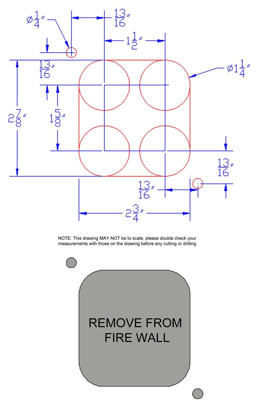
42 Bulkhead Template The following templete is only needed for Painless part # The dimension photo on the next page shows how you can cut the bulkhead hole clean and precise using a 1 ¼ hole saw to cut 4 holes, using a jigsaw or cut off wheel to connect the outsides of the 1 ¼ holes, and using a ¼ drill bit for the fuse block mounting holes. Mark the centers of all 6 holes (the 1 ¼ holes as well as the ¼ ) holes before any cutting is done.
43
Wire Harness Installation Instructions
 Wire Harness Installation Instructions For Installing: #10140 Customizable Weatherproof Chassis Harness 26 Circuit Manual #90531 Painless Performance Products, LLC 2501 Ludelle Street Fort Worth, TX 76105-1036
Wire Harness Installation Instructions
 Wire Harness Installation Instructions For Installing: Part #50001 Race Car Kit/8 Circuit Part #50201 8 Switch Dash Mounted Panel Part #50202 8 Switch Roll Bar Mounted Panel Manual #90502 Painless Performance
Wire Harness Installation Instructions
 Wire Harness Installation Instructions FOR INSTALLING: #10308 Basic Customizable Chassis Harness 18 Circuit Manual #90527 Painless Performance Products, LLC 2501 Ludelle Street Fort Worth, TX 76105-1036
Wire Harness Installation Instructions
 Wire Harness Installation Instructions FOR INSTALLING: PART #10130 14 CIRCUIT MICRO FUSE BLOCK REMOTE MOUNT HARNESS Manual #90525 Painless Performance Products Division Perfect Performance Products, LLC
Wire Harness Installation Instructions For Installing:
 Wire Harness Installation Instructions For Installing: #10120 Classic Customizable Trunk Mount Harness 21 Circuit #10220 Classic Plus Customizable Trunk Mount Harness 28 Circuit Painless Performance Products,
Wire Harness Installation Instructions
 Wire Harness Installation Instructions For Installing: #10101 Classic Customizable Harness-GM Keyed Column-21 Circuit #10102 Classic Customizable Harness-Non GM Keyed Column-21 Circuit #10103 Classic Customizable
Modular Wire Harness Installation Instructions
 Modular Wire Harness Installation Instructions 10301 MODULAR 4-CIRCUIT CHASSIS HARNESS Manual #90529 Painless Performance Products Division Perfect Performance Products, LLC 2501 Ludelle Street, Fort Worth,
Wire Harness Installation Instructions For Installing:
 Wire Harness Installation Instructions For Installing: #20106 Classic Plus Customizable Tri-Five Chevy Harness 28 Circuit #20107 Classic Customizable Tri-Five Chevy Harness 21 Circuit Manual #90553 Painless
Wire Harness Installation Instructions
 Wire Harness Installation Instructions For Installing: #10127 Customizable Mopar Chassis Harness 21 Circuit Manual #90542 Painless Performance Products, LLC 2501 Ludelle Street Fort Worth, TX 76105-1036
WIRE HARNESS INSTALLATION INSTRUCTIONS
 WIRE HARNESS INSTALLATION INSTRUCTIONS For Installing: #10206 Classic Plus Customizable GM Pickup Chassis Harness 1967-72 28 Circuit Manual #90510 PERFECT PERFORMANCE PRODUCTS, LLC Painless Performance
Wire Harness Installation Instructions
 Wire Harness Installation Instructions For Installing: Part #10143 Landcruiser / Scout Weatherproof Harness Manual #90548 Painless Performance Products Division Perfect Performance Products, LLC 2501 Ludelle
WIRE HARNESS INSTALLATION INSTRUCTIONS
 WIRE HARNESS INSTALLATION INSTRUCTIONS For Installing: #10205 Classic Plus Customizable GM Pickup Chassis Harness 1973-87 27 Circuit Manual #90507 Painless Performance Products, LLC 2501 Ludelle Street
Wire Harness Installation Instructions For Installing: #20102 Classic Plus Customizable GM Muscle Car Chassis Harness 25 Circuit
 Wire Harness Installation Instructions For Installing: #20102 Classic Plus Customizable 1969-74 GM Muscle Car Chassis Harness 25 Circuit Manual #90552 Painless Performance Products Division Perfect Performance
Wire Harness Installation Instructions
 Wire Harness Installation Instructions For Installing: Part #10107 Wiring Harness (Land Cruiser, Scout/12 circuit) Manual #90535 Painless Performance Products Division Perfect Performance Products, LLC
Wire Harness Installation Instructions
 Wire Harness Installation Instructions For Installing: #10112 Classic Customizable Chevy P/U Harness 19 Circuit Manual #90519 Perfect Performance Products, LLC Painless Performance Products Division 2501
Wire Harness Installation Instructions
 Wire Harness Installation Instructions FOR INSTALLING: PART #10108 20 CIRCUIT BRONCO HARNESS Manual #90521 Painless Performance Products Division Perfect Performance Products, LLC 2501 Ludelle Street,
Wire Harness Installation Instructions
 Wire Harness Installation Instructions For Installing: #10123 Customizable Ford Color Coded Harness 21 Circuit Manual #90545 Painless Performance Products, LLC 2501 Ludelle Street Fort Worth, TX 76105-1036
Wire Harness Installation Instructions
 Wire Harness Installation Instructions For Installing: #20101 Classic Plus Customizable 67-68 Camaro/Firebird Harness - 24 Circuit Manual #90551 Painless Performance Products Division Perfect Performance
Wire Harness Installation Instructions
 Wire Harness Installation Instructions For Installing: Part #20120 14 Circuit Ford Mustang (1965-1966) Manual #90526 Perfect Performance Products, LLC Painless Performance Products Division 2501 Ludelle
WIRE HARNESS INSTALLATION INSTRUCTIONS. For Installing: Part # Circuit Universal CJ Jeep Harness ( ) Manual #90513
 Manual #90513") WIRE HARNESS INSTALLATION INSTRUCTIONS For Installing: Part #10110 12 Circuit Universal CJ Jeep Harness (1975-86) Manual #90513 Perfect Performance Products, LLC Painless Performance Division 2501 Ludelle
WIRE HARNESS INSTALLATION INSTRUCTIONS For Installing: Part #10110 12 Circuit Universal CJ Jeep Harness (1975-86) Manual #90513 Perfect Performance Products, LLC Painless Performance Division 2501 Ludelle
jegs.com
 Contents Wiring Harness w/ Fuse Panel Installation Instructions Turn Signal Plug w/ Terminals 2 Headlight Plugs 3/4 Grommet 10 ¼ Terminals 4 Ring Terminals 10 Wire Ties Fusible Link 2 Screws & Nuts 2 Plastic
Off-Road Switch Panel Installation Instructions
 Off-Road Switch Panel Installation Instructions 50330: Off-road 4 Toggle switches/dash Mount w/keyed Ignition Switch 50332: Off-road 6 Toggle switches/dash Mount w/keyed Ignition Switch Painless Performance
Trail Rocker Installation
 Trail Rocker Installation Instructions Customizable Trail Rocker Control System For Installing Painless Part Number: 57100 Manual #90616 Painless Performance Products recommends you, the installer, read
Track Rocker Installation Instructions
 Track Rocker Installation Instructions For Installing Painless Part Numbers: 58103: 8-Switch Customizable Track Rocker Switch Panel w/ Flanged Mount 58106: 6-Switch Customizable Track Rocker Switch Panel
Wire Harness Installation Instructions
 Wire Harness Installation Instructions For Installing: #20121 Direct Fit Mustang Chassis Harness 1967-1968 22 Circuit Manual #90556 Perfect Performance Products, LLC Painless Performance Products Division
Wire Harness Installation Instructions
 Wire Harness Installation Instructions For Installing: Part #20120 22 Ford Mustang (1965-1966) Manual #90526 Perfect Performance Products, LLC Painless Performance Products Division 2501 Ludelle Street
Trail Rocker Installation
 Trail Rocker Installation Instructions 4, 6, or 8 - Switch Customizable Trail Rocker Switch Panel w/ Flanged Mount For Installing Painless Part Number: 57103, 57106, & 57109 Manual #90636 Painless Performance
INSTRUCTIONS. 20 Circuit Wiring Kit Instructions October 2009, Speedway Motors, Inc.
 1 MAIN FUSE PANEL The main fuse panel harness s designed to be mounted under the dash a the firewall in an area close to the steering column. The enclosed representation of the main dash harness shows
Trail Rocker Installation Instructions
 Trail Rocker Installation Instructions Manual #90580 For Installing Painless Part Numbers: 57000 and 57001 Painless Performance Products recommends you, the installer, read this installation manual from
Trail Rocker Installation Instructions
 Trail Rocker Installation Instructions Manual #90581 For Installing Painless Part Numbers: 57002 Painless Performance Products recommends you, the installer, read this installation manual from front to
Track Rocker Installation Instructions
 Track Rocker Installation Instructions Customizable Track Rocker Control System For Installing Painless Part Number: 58100 Track Rocker Relay Center Manual #90641 Painless Performance Products recommends
Wire Harness Installation Instructions
 Wire Harness Installation Instructions For Installing: Part #20122 14 Circuit 1969 1970 Ford Mustang Manual #90557 Perfect Performance Products, LLC Painless Performance Products Division 2501 Ludelle
Wire Harness Installation Instructions For Installing:
 Wire Harness Installation Instructions For Installing: #10117 Direct Fit 1967-77 F-Series Ford Truck Harness w/o es 21 Circuit or #10118 Direct Fit 1967-77 F-Series Ford Truck Harness w/ es 21 Circuit
Manual P/N Copyright Third Edition June 21, 2005
 P/N 60212, 60213, 60214 & 60215 1996-99 GM VORTEC WIRE HARNESS INSTALLATION INSTRUCTIONS Manual P/N 90524 Copyright 2003 Third Edition June 21, 2005 PAINLESS PERFORMANCE PRODUCTS 2501 Ludelle Street, Fort
Trail Rocker Installation Instructions
 Trail Rocker Installation Instructions Trail Rocker - Genesis Bracket For Installing Painless Part Number: 57200 Manual # 90591 To be used with Painless Kit # s: 57000-57005 Painless Performance Products
Installation Instructions
 Installation Instructions Part #40120 Perfect Performance Products, LLC Painless Performance Products Division 2501 Ludelle Street Fort Worth, TX 76105-1036 800-423-9696 phone 817-244-4024 fax Web Site:
Wire Harness Installation Instructions
 Wire Harness Installation Instructions For Installing: Part #60101 - GM 86-93 TBI Standard Harness & Part #60201 GM 86-93 TBI Extended Length Harness Manual # 90503 Painless Performance Products, LLC 2501
20 CIRCUIT ATO FUSE CENTER INSTALLATION INSTRUCTIONS
 2501 Ludelle Street Fort Worth, Texas 76105 817-244-6212 phone 817-244-4024 fax 800-423-9696 Tech E-Mail: painless@painlessperformance.com Web: www.painlessperformance.com 30003 20 CIRCUIT ATO FUSE CENTER
Installation Instructions For 50330, 50331, 50332, and Off Road Switch Panels
 Installation Instructions For 50330, 50331, 50332, and 50333 Off Road Switch Panels 2501 Ludelle Street Fort Worth, Texas 76105 817-244-6212 Phone 817-244-4024 Fax 888-350-6588 Sales 800-423-9696 Tech
Perfect Performance Products, LLC Painless Performance Products Division 2501 Ludelle St. Fort Worth, Texas (800)
") Wire Harness Installation Instructions For Installing: Part # 65104 Into 1985-1992 (5.0 & 5.7L) TPI Engines Manual # 90536 Perfect Performance Products, LLC Painless Performance Products Division 2501
Wire Harness Installation Instructions For Installing: Part # 65104 Into 1985-1992 (5.0 & 5.7L) TPI Engines Manual # 90536 Perfect Performance Products, LLC Painless Performance Products Division 2501
Installation Instructions. Part #65100
 Installation Instructions Part #65100 Perfect Performance Products, LLC Painless Performance Products Division 2501 Ludelle Street Fort Worth, TX 76105-1036 800-423-9696 phone 817-244-4024 fax Web Site:
Wire Harness Installation Instructions
 Wire Harness Installation Instructions For Installing: Part #60102 - GM 86-89 TPI Mass Air Flow (MAF) Standard Harness Part #60103 - GM 90-92 TPI w/speed Density (MAP) Standard Harness Part #60202 - GM
-----
 ----- - - -- - - -- - -- - - NOTE: #32 WIRE DOES NOT APPLY TO 8 AND 14 CIRCUIT HARNESSES ELECTRIC FAN #1 TO FAN SWITCH (GRAY) #21 TEMP. GAUGE (GREEN) #2 TO AC SWITCH (BLACK) JUMPER WIRE ALTERNATORS
CLASSIC UPDATE WIRING KIT
 by Randy Irwin 1955-57 CLASSIC UPDATE WIRING KIT Randy Irwin - Technical Writer Randy has been involved in the Chevy parts business for over 25 years. He is a wizard at creating, making and modifying custom
40A A 40B. Horn Relay Connector. Brake Switch. Third Brake Light. Brake Switch. Brake Switch. Wires. page 3. Rear Body Feed Wires.
 Fuse Box Connections (viewed from underside) 4D 4C 4D 0 50 300 4C 43 7 39 3 6 4 93 A 2G 2F 2E 2D 2C 2B 2G 2F 2E 40 69A 2 1 5 27 69A 3A B 40A,B 11A,B 40A 156 Dimmer Dome Feed page 2 Horn Relay 2D 2 29 40B
INSTRUCTIONS Circuit Wiring Kit Instructions _2017. Fuse Box Connections. (viewed from underside) 2018, Speedway Motors, Inc.
 2018, Speedway Motors, Inc.") Fuse Box Connections (viewed from underside) 4D 4C 100 50 300 4D 4C 4B 4A 43 107 39 103 3B 2G 104 93 2F 2E 2D 2C 2B 40 69A 102 101 105 2G 2F 2E 3A A 2A B 40A,B 27 69A 106 201, Speedway Motors, Inc. 1 Fuse
Fuse Box Connections (viewed from underside) 4D 4C 100 50 300 4D 4C 4B 4A 43 107 39 103 3B 2G 104 93 2F 2E 2D 2C 2B 40 69A 102 101 105 2G 2F 2E 3A A 2A B 40A,B 27 69A 106 201, Speedway Motors, Inc. 1 Fuse
P/N & GM LS2 FUEL INJECTION WIRE HARNESS INSTALLATION INSTRUCTIONS. Manual P/N 90543
 P/N 6050 & 6051 005-06 GM LS FUEL INJECTION WIRE HARNESS INSTALLATION INSTRUCTIONS Manual P/N 90543 1 Painless Performance Products, LLC 501 Ludelle Street Fort Worth, TX 76105-1036 800-43-9696 phone 817-44-404
INSTRUCTIONS 12 Circuit Wiring Kit Instructions
 Fan 47 9 56 4 7 6 72 40 45 48 5 8 6 Gauge Power Temp Sender Headlight Power Power Radio Constant Power Instruments and Dash Rear of Vehicle Ignition and Lights Fuse Panel & Front of Vehicle Horn Alt Excitor
P/N & GM LS1 w/mechanical (cable) THROTTLE BODY FUEL INJECTION WIRE HARNESS INSTALLATION INSTRUCTIONS
 THROTTLE BODY FUEL INJECTION WIRE HARNESS INSTALLATION INSTRUCTIONS") P/N 60508 & 60509 1997-0 GM LS1 w/mechanical (cable) THROTTLE BODY FUEL INJECTION WIRE HARNESS INSTALLATION INSTRUCTIONS Manual P/N 9050 Painless Performance Products, LLC 501 Ludelle Street Fort Worth,
P/N 60508 & 60509 1997-0 GM LS1 w/mechanical (cable) THROTTLE BODY FUEL INJECTION WIRE HARNESS INSTALLATION INSTRUCTIONS Manual P/N 9050 Painless Performance Products, LLC 501 Ludelle Street Fort Worth,
accessory connection rear body connection 40G 17A instrument cluster and map lamp ground 150A,B 15A 14A Circuit Branch 500A fog lamp switch
 accessory rear body 19 9 11 instrument cluster and map 10A, 0 4 3 7 40G 18 30 17A 24 1A 14A 9 8A instrument cluster 4E 31 3 121 11 33 401 10A 39A 400 30 washer and wiper switch 93A, 94 93 glovebox, map
P/N & GM LS1 FUEL INJECTION WIRE HARNESS INSTALLATION INSTRUCTIONS
 P/N 605 & 6053 00-04 GM LS1 FUEL INJECTION WIRE HARNESS INSTALLATION INSTRUCTIONS Manual P/N 90544 nd Edition July 014 PAINLESS PERFORMANCE PRODUCTS 501 Ludelle Street - Fort Worth, Texas 76105-1036 -
Wire Harness Installation Instructions Manual #90563
 Wire Harness Installation Instructions Manual #90563 For Installing: #10113 Direct Fit 1966-1977 Bronco Harness 28 Circuit w/switches Perfect Performance Products, LLC Painless Performance Products Division
Mustang Classic Update Series Kit
 accessory rear body 19 9 11 instrument cluster and map 10A, 0 4 3 7 40G 18 30 17A 24 1A 14A 9C 8A instrument cluster 4E 31 3 121 11 401 10A 3 400 30 washer and wiper switch 93A, 93 glovebox, map light,
WIRE SYSTEM PRO15 ULTRA SMALL 15 FUSE 24 CIRCUIT 118 TERMINAL PANEL WIRE SYSTEM
 TECH UPPORT: 503.693.1918 WIRE YTEM WWW.KEEPITCLEANWIRING.COM PRO15 ULTRA MALL 15 FUE 24 CIRCUIT 118 TERMINAL PANEL WIRE YTEM IMPORTANT: The below instructions are referring to a general installation.
Installation Instructions. Manual # For Installing: Part # Painless Gauge Controller
 Installation Instructions Manual #90579 For Installing: Part #60650- Painless Gauge Controller Perfect Performance Products, LLC Painless Performance Products Division 2501 Ludelle Street Fort Worth, TX
Wire Harness Installation Instructions
 Wire Harness Installation Instructions For Installing: Part #60102 - GM 86-89 TPI Mass Air Flow (MAF) Standard Harness Part #60103 - GM 90-92 TPI w/speed Density (MAP) Standard Harness Part #60202 - GM
Classic Update Series
 Classic Update Series 1964-1966 Ford Mustang START HERE! PLEASE READ THIS EFORE STARTING INSTALLATION! This wiring kit is designed for ease of installation. Please read the guidelines below, EFORE STARTING
P/N & /1995 GM LT1 FUEL INJECTION WIRE HARNESS INSTALLATION INSTRUCTIONS
 P/N 60502 & 60505 1994/1995 GM LT1 FUEL INJECTION WIRE HARNESS INSTALLATION INSTRUCTIONS Manual P/N 90517 Copyright May 2002 PAINLESS PERFORMANCE PRODUCTS 2501 Ludelle Street - Fort Worth, Texas 76105-1036
P/N & GM LS1 FUEL INJECTION WIRE P/N & GM LS1 FUEL INJECTION WIRE HARNESS INSTALLATION INSTRUCTIONS
 P/N 60506 & 60507 1997-98 GM LS1 FUEL INJECTION WIRE HARNESS INSTALLATION INSTRUCTIONS P/N 60508 & 60509 1999-0 GM LS1 FUEL INJECTION WIRE HARNESS INSTALLATION INSTRUCTIONS Manual P/N 9050 Seventh Edition
30107 & PACK & 6-PACK RELAY BANK
 30107 & 30108 2501 Ludelle Street Fort Worth, Texas 76105 817-244-6212 Phone 817-244-4024 Fax 888-350-6588 Sales 800-423-9696 Tech E-mail: painless@painlessperformance.com Web: www.painlessperformance.com
Opel Manta/Ascona/1900 Wiring Diagram (Based on using Universal EZ20 wiring harness)
") Opel Manta/Ascona/1900 Wiring Diagram (Based on using Universal EZ20 wiring harness) Index: 1 - Notes, egend, & Shipping Check ist i thru v - Instructions, Dos and Don'ts 2 - Fuse Box Diagram 3 - Front
Opel Manta/Ascona/1900 Wiring Diagram (Based on using Universal EZ20 wiring harness) Index: 1 - Notes, egend, & Shipping Check ist i thru v - Instructions, Dos and Don'ts 2 - Fuse Box Diagram 3 - Front
Installation Instructions For 50340
 Installation Instructions For 50340 2501 Ludelle Street Fort Worth, Texas 76105 817-244-6212 Phone 817-244-4024 Fax 888-350-6588 Sales 800-423-9696 Tech E-mail: painless@painlessperformance.com Web: www.painlessperformance.com
Step 1 Wiring your remote start. Installation Tips for your Remote Start system (for GM vehicles) V3.3 revised 9/12/2013
 V3.3 revised 9/12/2013") Installation Tips for your Remote Start system (for GM vehicles) V3.3 revised 9/12/2013 Thank you for purchasing your remote start from MyPushcart.com - an industry leader in providing remote starts to
Installation Tips for your Remote Start system (for GM vehicles) V3.3 revised 9/12/2013 Thank you for purchasing your remote start from MyPushcart.com - an industry leader in providing remote starts to
Rear Body 40D 156A 24 17A 151 3D. 8A,8B,8C under hood light. Horn Relay 91
 fuse box as viewed from the wire entry side Mating connector is plugged into Power Accessory connector 40D Rear Body 19 18 9B 30 LH Courtesy Light 40A,D 4D, 43 156B,C 16 16A 4C 3D 3C 16A 3G 4B 3G 116 4A&130
UNIVERSAL GAUGE WIRE HARNESS
 2650-1797-00 UNIVERSAL GAUGE WIRE HARNESS For Installing Auto Meter Electric Speedometer, Tachometer, And Short Sweep Electric Oil Pressure, Water Temperature, Fuel Level, and Volt Meter Gauges. This harness
Installation Tips for your Crimestopper/ProStart Remote Start system (for GM vehicles) v1.01 updated 2/27/2012
 v1.01 updated 2/27/2012") Installation Tips for your Crimestopper/ProStart Remote Start system (for GM vehicles) v1.01 updated 2/27/2012 Thank you for purchasing your remote start from MyPushcart.com - an industry leader in providing
Installation Tips for your Crimestopper/ProStart Remote Start system (for GM vehicles) v1.01 updated 2/27/2012 Thank you for purchasing your remote start from MyPushcart.com - an industry leader in providing
Wire Harness Installation Instructions Manual #90576 For Installing:
 Wire Harness Installation Instructions Manual #90576 For Installing: #20112 Direct Fit Camaro Harness 1970-73 #20113 Direct Fit Camaro Harness 1974-77 #20114 Direct Fit Camaro Harness 1978-81 All 26 Circuit
PIN BULKHEAD CONNECTOR KIT
 2501 Ludelle Street Fort Worth, Texas 76105 817-244-6212 Phone 817-244-4024 Fax 888-350-6588 Sales 800-423-9696 Tech E-mail: painless@painlessperformance.com Web: www.painlessperformance.com 40130 22 PIN
Installation Tips for your Remote Start/Keyless Entry (for Ford Vehicles) v3.3 Updated 1/13/2013
 v3.3 Updated 1/13/2013") Installation Tips for your Remote Start/Keyless Entry (for Ford Vehicles) v3.3 Updated 1/13/2013 Thank you for purchasing your remote start from MyPushcart.com - an industry leader in providing remote
Installation Tips for your Remote Start/Keyless Entry (for Ford Vehicles) v3.3 Updated 1/13/2013 Thank you for purchasing your remote start from MyPushcart.com - an industry leader in providing remote
UNIVERSAL WIRING HARNESS Installation Manual
 UNIVERSAL WIRING HARNESS Installation Manual Terminals are provided for most connections on your wiring kit. Following the gauge manufacturer s instructions, use the terminals supplied with your gauge
Installation Tips Crimestopper/ProStart Remote Start system + PLJX + DLRM + SPDT (for GM vehicles) T0760 v1.1 updated 2/5/14
 T0760 v1.1 updated 2/5/14") Installation Tips Crimestopper/ProStart Remote Start system + PLJX + DLRM + SPDT (for GM vehicles) T0760 v1.1 updated 2/5/14 Thank you for purchasing your remote start from MyPushcart.com - an industry
Installation Tips Crimestopper/ProStart Remote Start system + PLJX + DLRM + SPDT (for GM vehicles) T0760 v1.1 updated 2/5/14 Thank you for purchasing your remote start from MyPushcart.com - an industry
Wire Harness Installation Instructions Manual #90571 PART 1 For Installing: #10309 Basic Customizable Nostalgia All Black Chassis Harness 17 Circuit
 Wire Harness Installation Instructions Manual #90571 PART 1 For Installing: #10309 Basic Customizable Nostalgia All Black Chassis Harness 17 Circuit Painless Performance Products recommends you, the installer,
29048, 29049, 29050, 29051, 29052, 29053, 29054,
 April 15, 2014 Lit. No. 29225, Rev. 11 29048, 29049, 29050, 29051, 29052, 29053, 29054, 29400 5 HARNESS KIT 3 PORT ISOLATION MODULE LIGHT SYSTEM w/2 PLUG SYSTEM HARNESSES Installation Instructions Read
Installation Instructions For #64066 Striker I Power Module Ford Powerstroke 6.0L Diesel Copyright
 Installation Instructions For #64066 Striker I Power Module 2003-2006 Ford Powerstroke 6.0L Diesel 2 nd Edition August 2007 Copyright 2006 by Perfect Performance Products, LLC 2501 Ludelle Street Fort
Installation Tips for your Remote Start system (for Toyota Camry & Prius C, ) Crimestopper RS0+ EVO-ALL T3468 rev#1.
 Crimestopper RS0+ EVO-ALL T3468 rev#1.") Installation Tips for your Remote Start system (for Toyota Camry & Prius C, 2012-2014) Crimestopper RS0+ EVO-ALL T3468 rev#1.1 1/22/2015 Thank you for purchasing your remote start from MyPushcart.com -
Installation Tips for your Remote Start system (for Toyota Camry & Prius C, 2012-2014) Crimestopper RS0+ EVO-ALL T3468 rev#1.1 1/22/2015 Thank you for purchasing your remote start from MyPushcart.com -
Wire Harness Installation Manual # Part # 60617
 Wire Harness Installation Manual #90572 For Installing: Part # 60617 26 Circuit/7 Relay 4.8L-6.0 L w/4l60e Integrated Harnesses Perfect Performance Products, LLC Painless Performance Products Division
Installation Instructions
 Installation Instructions Jeep JK Unlimited (2007 Present) Mounting Bracket and Air Line System Kit for ARB On-Board Twin Air Compressor (CKMTA12) Made in the USA Kit Contents: 1 Bracket for ARB Compressor
Cutlass & F85. Oldsmobile. Wiring Harnesses. item# year description price. Cutlass/F85 PHONE YOUR ORDER FAX YOUR ORDER
 866-405-1367 207 AIR CONDITIONING HARNESSES 06045 1964-1964 AIR CONDITIONING HARNESS, V8 $118.00 09370 1965-1965 AIR CONDITIONING HARNESS, V8 $118.00 09450 1966-1966 AIR CONDITIONING HARNESS, V8 $118.00
TIP SHEET. Installation Tips for your RS OL-MDB-CH6 (1) (for Jeep vehicles) T1227 v1.0 3/19/14
 (for Jeep vehicles) T1227 v1.0 3/19/14") TIP SHEET Installation Tips for your RS-360 + OL-MDB-CH6 (1) (for Jeep vehicles) T1227 v1.0 3/19/14 Thank you for purchasing your remote start from MyPushcart.com - an industry leader in providing remote
TIP SHEET Installation Tips for your RS-360 + OL-MDB-CH6 (1) (for Jeep vehicles) T1227 v1.0 3/19/14 Thank you for purchasing your remote start from MyPushcart.com - an industry leader in providing remote
Installation Tips for your Remote Start system (for RS4LX>GMBP for GM vehicles)
") Installation Tips for your Remote Start system (for RS4LX>GMBP for GM vehicles) Thank you for purchasing your remote start from MyPushcart.com - an industry leader in providing remote starts to doit-yourself
Installation Tips for your Remote Start system (for RS4LX>GMBP for GM vehicles) Thank you for purchasing your remote start from MyPushcart.com - an industry leader in providing remote starts to doit-yourself
Headlight Switch Connector. Brake Switch. Lead Wires. Main Power Feed from Starter. Fuse Box Connections (viewed from underside)
") www.americanautowire.com 86-933-0801 TH KT DOE NOT UPPORT TOCK (ORGNAL) GENERATOR. THE DEGN OF THE KT DEGNED TO UPPLY MORE POWER THAN THE GENERATOR ALE TO UPPLY. 16 68A 4D 4C 4D 0 0 0 4C 4 43 7 39 3 Dimmer
www.americanautowire.com 86-933-0801 TH KT DOE NOT UPPORT TOCK (ORGNAL) GENERATOR. THE DEGN OF THE KT DEGNED TO UPPLY MORE POWER THAN THE GENERATOR ALE TO UPPLY. 16 68A 4D 4C 4D 0 0 0 4C 4 43 7 39 3 Dimmer
Replace light bulb with the same number bulb as the one removed. White Wire: Connect to +12 Volt Lighting
 INSTALLATION INSTRUCTIONS SHORT SWEEP ELECTRIC GAUGES 2650-1079-00 Rev. C CAUTION FOR ALL GAUGE INSTALLATION (AMMETERS EXCLUDED) As a safety precaution, the +12V wire attached to the positive I (+) terminal
8436, 8437, 8438, 8439, 8442, 27480, 27780, 28028, & ISOLATION MODULE ELECTRICAL SYSTEM
 September 11, 2003 Lit. No. 27808 8436, 8437, 8438, 8439, 8442, 27480, 27780, 28028, & 28400 ISOLATION MODULE ELECTRICAL SYSTEM Installation Instructions Read this document before installing the snowplow.
For Installing Harness Number: Manual #90627
 Wire Harness Installation Instructions For Installing Harness Number: 20205: 27 Circuit 1973-1987 GM Truck Manual #90627 Painless Performance Products recommends you, the installer, read this installation
Instrument Cluster 30 33B 39B A B C D E F E F G H J. Connector. Circuit Branch #4. Circuit Branch #5. Circuit. Branch #6 150A. Ground.
 16 4D, 43 4B 4A & 130 100 50 39A,B,C 300 4C 4B 4C 107 3C 3D 3C 3G 3B 3F 3A 16A 3G 116 104 93 3B 3D 2E 16A 2C 2D 2B 2A 44 40 27A 40B 115 27 40A,C,E 8A,B,C Mating is plugged into accessory connector Power
Installation Tips for your Add-on Remote Start (for GM vehicles with INTSL Install 2) v3.2 Updated 11/12/2012
 v3.2 Updated 11/12/2012") Installation Tips for your Add-on Remote Start (for GM vehicles with INTSL Install 2) v3.2 Updated 11/12/2012 Thank you for purchasing your remote start from MyPushcart.com - an industry leader in providing
Installation Tips for your Add-on Remote Start (for GM vehicles with INTSL Install 2) v3.2 Updated 11/12/2012 Thank you for purchasing your remote start from MyPushcart.com - an industry leader in providing
Classic Update Series
 Classic Update Series 0-4 Ford Falcon and 0- Mercury Comet end view of terminal START HERE! PLEASE READ THIS EFORE STARTING INSTALLATION! This wiring kit is designed for ease of installation. Please read
Vortec Drive by Cable Electronic Fuel Injection Wiring Harness (P/N HAR-1018) HAR-1018
 HAR-1018") 1998 2002 Vortec Drive by Cable Electronic Fuel Injection Wiring Harness (P/N HAR-1018) HAR-1018 PERFORMANCE SYSTEMS INTEGRATION 170 Oberlin Ave N Suite 13 Lakewood NJ 08701-4548 Ph: 732-444-3277 Email:
1998 2002 Vortec Drive by Cable Electronic Fuel Injection Wiring Harness (P/N HAR-1018) HAR-1018 PERFORMANCE SYSTEMS INTEGRATION 170 Oberlin Ave N Suite 13 Lakewood NJ 08701-4548 Ph: 732-444-3277 Email:
Installation Tips for your Crimestopper/ProStart Remote Start system (add-on for GM vehicles) v1.02 updated 1/16/2013
 v1.02 updated 1/16/2013") Installation Tips for your Crimestopper/ProStart Remote Start system (add-on for GM vehicles) v1.02 updated 1/16/2013 Thank you for purchasing your remote start from MyPushcart.com - an industry leader
Installation Tips for your Crimestopper/ProStart Remote Start system (add-on for GM vehicles) v1.02 updated 1/16/2013 Thank you for purchasing your remote start from MyPushcart.com - an industry leader
Classic Update Series
 Classic Update Series 62-65 Ford Fairlane and 62-63 Mercury Meteor end view of terminal START HERE! PLEASE READ THIS EFORE STARTING INSTALLATION! This wiring kit is designed for ease of installation. Please
Installation Tips for your Excalibur Remote Start (for Honda and Acura Vehicles) rev 11/28/2012
 rev 11/28/2012") Installation Tips for your Excalibur Remote Start (for Honda and Acura Vehicles) rev 11/28/2012 Thank you for purchasing your remote start from MyPushcart.com - an industry leader in providing remote starts
Installation Tips for your Excalibur Remote Start (for Honda and Acura Vehicles) rev 11/28/2012 Thank you for purchasing your remote start from MyPushcart.com - an industry leader in providing remote starts
Installation Tips for RS1 + EVO-RIDE + SPDT. *(reglar key, automatic transmission vehicles ONLY)*
*") Installation Tips for RS1 + EVO-RIDE + SPDT TIP SHEET T1235 *(reglar key, automatic transmission vehicles ONLY)* Thank you for purchasing your remote start from MyPushcart.com - an industry leader in providing
Installation Tips for RS1 + EVO-RIDE + SPDT TIP SHEET T1235 *(reglar key, automatic transmission vehicles ONLY)* Thank you for purchasing your remote start from MyPushcart.com - an industry leader in providing
Read the entire installation manual. There are several safety tips there that you need to know before you start
 Installation Tips for RS4 + INTSL (2) TIP SHEET T0749 Buick Century: 2000-2005 Buick LeSabre: 2000-2005 Buick Park Avenue: 1999-2005 Buick Ranier: 2004-2007 Cadillac Escalade: 2003-2007 Chevrolet Avalanche:
headlights [H only] dip switch hi beam flasher pillar interior lights rear interior panel switch C/D cubby A B boot map light LED strip
![headlights [H only] dip switch hi beam flasher pillar interior lights rear interior panel switch C/D cubby A B boot map light LED strip](/thumbs/74/70768506.jpg "headlights [H only] dip switch hi beam flasher pillar interior lights rear interior panel switch C/D cubby A B boot map light LED strip") to Alpine unit exterior lights [S or H or F] FUSE BOX LIGHTS ENGINE ACC reverse light, brake Note: diode (6a 50v) prevents triggering of Alpine backup camera when brake light is closed brake L tail plate
to Alpine unit exterior lights [S or H or F] FUSE BOX LIGHTS ENGINE ACC reverse light, brake Note: diode (6a 50v) prevents triggering of Alpine backup camera when brake light is closed brake L tail plate
ISIS Power Manual and Installation Guide Race Car Replicas- Superlite Coupe
 ISIS Power Manual and Installation Guide Race Car Replicas- Superlite Coupe Table of Contents Overview... 2 System Details... 3 Kit Includes... 3 Technical Specifications... 3 Harness Descriptions... 4
29048, 29049, 29050, 29051, 29052, 20953, 29054,
 July 15, 2008 Lit. No. 29225, Rev. 06 29048, 29049, 29050, 29051, 29052, 20953, 29054, 29400-2 HARNESS KIT 3-PORT ISOLATION MODULE LIGHT SYSTEM w/2-plug SYSTEM HARNESSES Installation Instructions Read
Installation Tips for your Remote Start w/ Keyless Entry (Toyota Vehicles) v3.2 Updated 3/14/13
 v3.2 Updated 3/14/13") Installation Tips for your Remote Start w/ Keyless Entry (Toyota Vehicles) v3.2 Updated 3/14/13 Thank you for purchasing your remote start from MyPushcart.com an industry leader in providing remote starts
Installation Tips for your Remote Start w/ Keyless Entry (Toyota Vehicles) v3.2 Updated 3/14/13 Thank you for purchasing your remote start from MyPushcart.com an industry leader in providing remote starts
Installation Tips for your GMDLBP + Excalibur Remote Start system (for GM vehicles) v1.01 updated 10/09/13
 v1.01 updated 10/09/13") Installation Tips for your GMDLBP + Excalibur Remote Start system (for GM vehicles) v1.01 updated 10/09/13 Thank you for purchasing your remote start from MyPushcart.com - an industry leader in providing
Installation Tips for your GMDLBP + Excalibur Remote Start system (for GM vehicles) v1.01 updated 10/09/13 Thank you for purchasing your remote start from MyPushcart.com - an industry leader in providing
Installation Instructions For #64320 Striker Turbo Timer Module
 2501 Ludelle Street Fort Worth, Texas 76105 817-244-6212 Phone 817-244-4024 Fax 888-350-6588 Sales 800-423-9696 Tech E-mail: painless@painlessperformance.com Web: www.painlessperformance.com Installation
Classic Update Series
 Classic Update Series 73-79 Ford F100-350 & 78-9 Ford ronco START HERE! PLEASE READ THIS EFORE STARTING INSTALLATION! This wiring kit is designed for ease of installation. Please read the guidelines below,