Warnings and Cautions
|
|
|
- Naomi Bradford
- 5 years ago
- Views:
Transcription
1
2 Warnings and Cautions WARNINGS: APPLICATION 1. ARO valves are designed for use only in industrial pneumatic (air) and / or vacuum systems applications and are NOT to be used for individual consumer use, application or service. 2. When any ARO valve is used in any type application, safeguards must be provided to insure against bodily injury for the operator and / or persons in the immediate area. 3. ARO valves are NOT to be used as a safety device or to operate and / or control the operator of full revolution clutch systems and / or brake systems on power presses or similar equipment. ARO valves are not designed or intended for such uses. LUBRICATION Valve components are lubricated at the time of assembly at the factory and can normally be operated without air line lubrication to an approximate life of twenty million cycles, depending on application. If air line cylinders, or other air line devices used in conjunction with ARO valves require lubrication, be sure the lubricating oils used are compatible with the valve seals and are of sufficient viscosity to assure adequate lubrication. Aro recommends an oil lubricant with a viscosity of SUS at 100?F. Aro does not recommend the use of compound oils containing graphite fillers, extremely low viscosities and other non-fluidic lubricants. RECOMMENDED: Aro air line lubricator oil is available in one quart containers. WARNINGS: INSTALLATION AND SERVICE 1. Shut off, disconnect and exhaust air pressure from system before installing or performing service to any ARO valve. 2. Shut off and disconnect electrical supply to system before installing or performing service to any ARO valve. 3. Allow only persons with a thorough understanding of the operation and application of all ARO valves being used in a particular system and how the ARO valve(s) relate to and interact with other components of the system to install or perform maintenance or service to any ARO valve or other components of the system. 4. DO NOT subject any ARO valve to any condition that exceeds the limits set forth in the specifications for a particular valve model. 5. When a manually operated (actuated) valve is used or installed into a system, provisions must be made to prevent the valve from being accidentally operated (actuated), which may in turn cause bodily injury or otherwise cause a hazardous or dangerous condition. 6. Damaged air pressure hoses or electrical wiring, or connections, can cause accidental valve operation (actuation), which may in turn cause accidental valve operation (actuation), which may in turn cause bodily injury or otherwise cause a hazardous or C/Manuals/Model 1384.doc
3 dangerous condition. KEEP ALL HOSES, ELECTICAL WIRING, FITTINGS AND CONNECTIONS IN FIRST CLASS OPERATING CONDITION. 7. ARO 2-POSITION, 4-WAY VALVES: Regardless of which of the 2-positions this type of ARO valve is in, when air pressure is applied to the inlet port (s) of these valves, there will always be an open flow path of air from the inlet to one of the valve outlets. A method to exhaust this trapped air pressure must be installed into the system so all air pressure can be removed from valve or system before performing service or maintenance to valve. 8. ARO 3-POSITION, 4-WAY VALVES: To actuate this type of ARO valve, either a double solenoid, double remote air pilot pressure or manual operation is used. When the valve actuator has shifted the valve, air pressure applied at the interport (s) will flow thru the valve to one of the two outlet ports. When the valve is not in a shifted position, the valve will automatically move to a center position. ARO valves can be either closed center or open center type and will reveal the following characteristics when the valve is in the center position. a. OPEN CENTER VALVES: When this type ARO valve is in the center position the inlet port(s) is blocked and the two outlet ports are open to the exhaust port(s) of the valve. With this type valve, in the center position air pressure is not present at either outlet port. Do not use this type ARO valve if exhausting the air pressure from the valve will cause hazardous or dangerous condition. b. CLOSED CENTER VALVES: When this type valve is in the center position all inlet, outlet and exhaust ports are blocked. Do not use this type valve if having the air pressure blocked at the port(s) may cause a dangerous or hazardous condition in the application, installation and / or servicing of an ARO valve. These valves must not be used to control load holding devices without an additional mechanical positive stop on the holding device. C/Manuals/Model 1384.doc
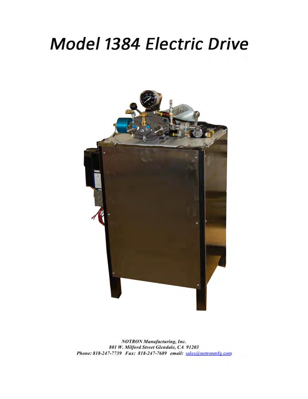
4 MODEL 1384-L CONTINUOUS ROTARY PRESSURE MIXER SUGGESTED MAINTENANCE: 1. Wipe off exposed metering cylinder shafts each morning to prevent seal damage. 2. Drain air line filter / water trap. Weekly: 1. Check oil level in air line lubricator and refill if necessary. (Use only10 W nondetergent oil or equivalent). 2. Check level in pump shaft lube wells and refill if necessary. (Use mineral or castor oil only). 3. Stir accelerator material each Monday to prevent settling. 4. Make visual inspection of mixer checking for loose or worn hoses. Also check for excessive air or material leakage. Monthly: 1. Tighten metering cylinder packing gland nuts, on the lower end only. (Never more than 1/6 turn at one time). Do not tighten upper packing gland nuts. 2. Tighten pump shaft lube wells. Daily Operating Procedures: 1. Remove mixing head assembly from freezer and thaw. a minutes thaw at room temperature. b. 5 minutes thaw when using warm water at 125 F. 2. Turn on coolant unit water pump off. 3. Turn on main air valve. 4. With mixing head removed, place paper napkin in mixing bracket chamber; push start button several times until base and accelerator are flowing into chamber. a. This will show inlet ports are free and clear. b. If accelerator does not flow in a reasonable time, remove accelerator automatic shut off and clean orifices. 5. Place in mixing head unit and lock. 6. Turn on water pump. 7. Meter gauges. Slightly higher when starting cold. 8 Important: If gauge records high pressure, stop machine and check orifice at accelerator automatic shut off valve. 9. Normal flow rate to fill six-ounce cartridge a. The base pump air pressure controls the flow rate. Normal air pressure approximately PST. C/Manuals/Model 1384.doc
5 b. To maintain a balanced system with the accelerator meter gauges showing, regulate the accelerator pump until you have a balance or slightly higher back pressure reading. Approximate pressure 25/30 PSI. c. Cold start, these gauge pressures will be higher. 10. Take button samples. C/Manuals/Model 1384.doc
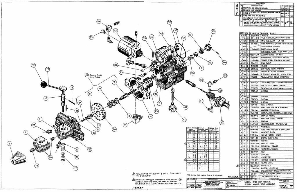
6 SPARE PARTS MODEL 1384 L MIXER 1 each Seal Kit 1 each Rear Seal 1 each Bearing 1 each Bearing 1 each Seal 2 each O-Ring 4 each O-Ring 1 each O-Ring 1 each O-Ring 1 each O-Ring 1 each Base Meter Seal Kit 1 each Accelerator Seal Kit (note: please indicate ratio by volume) 1 each Cap Assembly 1 each Rotor Housing 2 each Wiper Ring, 55 Gallon 1 each Wiper Ring, 5 Gallon 4 each Cup Seal, Teflon 4 each Cotter Pin 4 each L31033 Gasket 2 each L34296 O-Ring 4 each L34309 O-Ring 2 each L48614 Washer 2 each L83849 Packing and Retainer 2 each L34401 U-Cup Packing C/Manuals/Model 1384.doc
7 SEAL KIT MODEL 1384-L H. V. MIXING HEAD MIXING HEAD: 1 each Rear Seal 1 each Bearing 1 each Bearing 1 each Seal 1 each P-1 Poppet 2 each O-Ring 2 each O-Ring 1 each O-Ring 1 each O-Ring 1 each O-Ring BASE SHUT OFF VALVE: 1 each O-Ring 1 each Fiber Washer 1 each Female Washer 3 each Chevron Seal 1 each Male Washer ASSCELERATOR SHUT OFF VALVE: 1 each O-Ring 2 each O-Ring 2 each O-Ring 1 each O-Ring 1 each O-Ring C/Manuals/Model 1384.doc
8
9
10
11
12
13
14
15
16
17
18

19

20

21


22

23


24

25
26
27
28
29


30
#9040 FUEL TANK SWEEPER
 #9040 FUEL TANK SWEEPER INSTRUCTION MANUAL FILTERS AND REMOVES FINE BIO-CONTAMINANTS, ALGAE, ETC. SWEEPING PROCESS REMOVES LARGE CONTAMINANTS FROM OIL TANKS SUCH AS RUST, WATER, CRUDE AND DIRT CIRCULATES
Principals of Operation... 1 Rotary Vane Priming Pump VPE and VPES... 2 Rotary Vane Priming Pump VPO and VPOS Priming Valve...
 Priming Systems Installation Priming Systems Operation & Maintenance Form No. F 1031 Section 2312 Issue Date 10/07/94 Rev. Date 02/27/06 Table of Contents Illustrations Principals of Operation...........................
Models
 Models 15300 15301 15500 15501 SAFETY PRECAUTIONS WARNING! To prevent personal injury, Wear goggles when working with refrigerants. Contact with refrigerants may cause injury. Incorrect use or connections
Sinclair Collins. Process Control Valves. For Steam, Hot and Cold Liquids -40 to 450 F up to 500 psi. Catalog SCV-100/USA April 2001
 Sinclair Collins Process Control Valves For Steam, Hot and Cold Liquids -40 to 450 F up to 500 psi April 2001 The Diaphragm Operated Valves on the following pages are designed for directing, diverting
Pressure Control Valves
 Control Valves DR8- Reducing/Relieving, Direct Acting, Spool Type 4 gpm (5 l/min) 6 psi (4 bar) Description A screw-in cartridge, direct acting, spool type, pressure reducing/relieving valve with internal
Service and Parts Manual. Minimum Filtration Required:
 R GRESEN Hydraulics Model V0 Sectional Body Directional Control Valve Service and Parts Manual Maximum Operating Pressure: Minimum Filtration Required: 00 PSI ( bar) 0 Micron The information in this Service
INSTALLATION INSTRUCTIONS FOR THE TRUCK MOUNTED VIPER ADDITIVE INJECTION SYSTEM GTP-8776C
 INSTALLATION INSTRUCTIONS FOR THE TRUCK MOUNTED VIPER ADDITIVE INJECTION SYSTEM GTP-8776C This additive injection system was designed to be used with five gallon jug of additive. The system is supplied
AF0465-XX SERVICE KITS GENERAL DESCRIPTION MODEL DESCRIPTION CHART OPERATING AND SAFETY PRECAUTIONS THIS MANUAL COVERS THE FOLLOWING MODELS
 OPERATOR S MANUAL INCLUDING: SERVICE KITS, TROUBLESHOOTING, PARTS LIST, DISASSEMBLY & REASSEMBLY. 4-1/4 AIR MOTORS AF044X-XX (4 STROKE) and AF046X-XX (6 STROKE) Also covers 637489 service kits AF044X-XX
5020 Series Injector
 5.2018.9.k 1 5020 Series Injector 1 2 3 4 5 6 10 11 7 12 13 8 2 14 Parts List 15 16 17 Item # Part # # Reqd. Description Material Alternate Part # 1 A-1854 1 0-12 PSI Pressure Gauge A-1295SS 2 A-0022 1
INSTRUCTION MANUAL AND PARTS LIST FOR 3E CANNED MOTOR PUMPS
 TM INSTRUCTION MANUAL AND PARTS LIST FOR 3E CANNED MOTOR PUMPS WARNING This Special Instruction Manual and General Instructions Manual, CA-1, should be read thoroughly prior to pump installation, operation
Suggested Installation & Operating Instructions for Sidewinder Pumps
 Models 40G / H / 80G P.O. Box 80769 Lafayette, LA 70598-0769 (337) 235-9838 FAX (337) 235-9852 www.sidewinderpumps.com Pneumatic Powered - Plunger Pumps Suggested Installation & Operating Instructions
Suggested Installation & Operating Instructions for Sidewinder Pumps
 Model 40 E Series Lube Pump P.O. Box 80769 Lafayette, LA 70598-0769 (337) 235-9838 FAX (337) 235-9852 www.sidewinderpumps.com Pneumatic Powered - Plunger Pumps Suggested Installation & Operating Instructions
SBM TECHNOLOGY Cooling / Air Recovery Valve
 SBM TECHNOLOGY Cooling / Air Recovery Valve Part no. VSP15203x Advanced high pressure seal technology Integrated non-return valve Robust, compact & lightweight design Proven & reliable technology Maintenance
Operating Manual. High Performance Vacuum Pump Models and 15600
 Operating Manual High Performance Vacuum Pump Models 15400 and 15600 CoolTech High Performance Vacuum Pumps Congratulations on purchasing one of Robinair s top quality CoolTech vacuum pumps. Your pump
UV PROCESS SUPPLY, INC. CON-TROL-CURE ½ DIAPHRAGM PUMP INSTRUCTION MANUAL PART # J
 1 IMPORTANT: READ THIS MANUAL CAREFULLY BEFORE INSTALLING, OPERATING OR SERVICING. PUMP DATA TYPE: MAT'L: WEIGHT: Air Operated Double Diaphragm Polypropylene or PVDF or Acetal PVDF (Polyvinylidene Fluoride)
Vickers 45. VMQ Series 30 Vane Pumps. Fixed Displacement, For Industrial and Mobile Applications (4.188)
") [ (4.188) 49,4 (1.94) /21,8 /.86) 174,7/172,3 (6.88/6.78) 332,9/33,5 (13.11/13.1) "M" is marked if metric port threads No marking if inch port threads AS-568-152 O-ring Vickers 45 65,3 (2.57) 13 (5.1 VMQ
[ (4.188) 49,4 (1.94) /21,8 /.86) 174,7/172,3 (6.88/6.78) 332,9/33,5 (13.11/13.1) "M" is marked if metric port threads No marking if inch port threads AS-568-152 O-ring Vickers 45 65,3 (2.57) 13 (5.1 VMQ
Troubleshooting the Transmission Hydraulic System
 Testing and Adjusting IT28F INTEGRATED TOOLCARRIER POWER TRAIN Testing And Adjusting Introduction Reference: For Specifications with illustrations, refer to SENR5974, IT28F Integrated Toolcarrier Power
Pneumatic Power Valves Series 75/76 Manual, Mechanical, Pneumatic and Electric Valves
 Quic-Pics Catalogue Pneumatic Power Valves Series 75/76 Manual, Mechanical, Pneumatic and Electric Valves Contents: Product Line Overviews 2 Manually Operated Valves 5 Pushbuttons 6 Toggle Switch 8 Knob
John Crane Type 5620 and 5620PR Dual O-Ring Cartridge Seal Assembly and Installation Instructions
 I-5620/5620PR-A John Crane Type 5620 and 5620PR Dual O-Ring Cartridge Seal Assembly and Installation Instructions Foreword These instructions are provided to familiarize the user with the seal and its
Series Single seated top guided control valve. Preventive maintenance. Overhauling procedure. Wörth am Main SERVICE NOTE. Control Valve Division
 Series 2000 Single seated top guided control valve Subject to change without notice Fig. 1: Series 2000 valve assembly Preventive maintenance Preventive maintenance consists of making a periodic visual
ANGLE SEAT AIR ACTUATED VALVES 2 Way (2/2)
") ANGLE SEAT AIR ACTUATED VALVES 2 Way (2/2) BRASS OR STAINLESS STEEL BODY POLYMER OR METAL ACTUATOR HERION USA Inc. Valve Technology and Systems Brochure N-285 Multi-Accessory Polymer Head versions Increased
ANGLE SEAT AIR ACTUATED VALVES 2 Way (2/2) BRASS OR STAINLESS STEEL BODY POLYMER OR METAL ACTUATOR HERION USA Inc. Valve Technology and Systems Brochure N-285 Multi-Accessory Polymer Head versions Increased
TWO HAND NON-TIE-DOWN CONTROLS SC SERIES
 TWO HAND NON-TIE-DOWN CONTROLS SC SERIES Complete Engineered Solutions Dynamco s SC Series of Two Hand Non-Tie-Down controls offers an engineered and completely assembled control product that can be used
Priming Systems Installation Instructions
 Priming Systems Installation Instructions System Components: Single Priming Pump: Single VAP Valve Systems: Control Panel Activated... 2 Auto Prime (Pressure Switch) Activated... 3 Multiple VAP Valve Systems...
Appendix A. Standard Symbols for Hydraulic Components
 Table B.1 Flow lines Appendix A Standard Symbols for Components Continuous flow E Pilot connection L L>10E E Drain connection L L
DELTA O-RING CARTRIDGE SEAL ASSEMBLY AND INSTALLATION INSTRUCTIONS INTRODUCTION:
 DELTA O-RING CARTRIDGE SEAL ASSEMBLY AND INSTALLATION INSTRUCTIONS INTRODUCTION: These instructions are provided to familiarize the user with the seal and its use. The instructions must be read carefully
Warning and Safety Precautions
 EXPRESS WARRANTY AND DISCLAIMER OF IMPLIED WARRANTIES Lily Corporation unconditionally guarantees its products to be free of defects in material or workmanship and further warrants that, for a period of
OPERATOR S MANUAL X INCLUDING: OPERATION, INSTALLATION & MAINTENANCE
 OPERATOR S MANUAL 651616-X INCLUDING: OPERATION, INSTALLATION & MAINTENANCE INCLUDE MANUALS: 66516 X FOLLOWER PLATE (PN 97999 854), 67195 X FOLLOWER PLATE (PN 97999 841) & S 635 GENERAL INFORMATION (PN
MEP-A Press safety valves
 MEP-A Press safety valves Definition MEP-A is a series of safety valves for presses and pneumatically acting safety subject groups; they are 3 way/2 pos. NC active components for compressed air powered
Installation, Operation, and Maintenance Manual
 Installation, Operation, and Maintenance Manual Welker Flanged Liquid Sampler Model LSS-1F Drawing No.: AD478BF.1 Manual No.: IOM-140 The information in this manual has been carefully checked for accuracy
CAB TILT HYDRAULIC SYSTEM
 OPERATION, MAINTENANCE and SERVICE INSTRUCTIONS CAB TILT HYDRAULIC SYSTEM WITH POWER-PACKER PUMP, CYLINDERS and LATCHES A division of Actuant Corporation 1-800-745-4142 1 www.powerpackerus.com Notice The
M-5000TG/5700TG Steam and Cold Water Mixing Unit
 M-5000TG/5700TG Steam and Cold Water Mixing Unit Installation, Operating and Maintenance Instructions Last Updated: October, 2012 Strahman Valves, Inc. USA Headquarters 2801 Baglyos Circle Bethlehem, PA
M-5000TG/5700TG Steam and Cold Water Mixing Unit
 M-5000TG/5700TG Steam and Cold Water Mixing Unit Installation, Operating and Maintenance Instructions Last Updated: August, 2014 Strahman Valves, Inc. USA Headquarters 2801 Baglyos Circle Bethlehem, PA
26-LU-L BRACKET-CARRIAGE AND EQUIPMENT, PART NO
 26-LU-L BRACKET-CARRIAGE AND EQUIPMENT, PART NO. 655031 OCTOBER, 2006 NOTE: The following description and operation is based on this device and its components being new or this device and its components
DODGE COOL LUBE 2 for Sleevoil Pillow Blocks Part Numbers , , ,
 DODGE COOL LUBE for Sleevoil Pillow Blocks Part s 063487, 063488, 07889, 07890 These instructions must be read thoroughly before installing or operating this product. WARNING: To ensure the drive is not
MODELS 9917, , 9946P and 9989 High Pressure Lubrigun Series A
 MODELS 9917, 9917-57, 9946P and 9989 Series A NOTE: Pails and Drums shown for illustration only. not included with models. MAR - 2007 Section - A5 Page - 84 DESCRIPTION Models 9917, 9917-57, 9946P, and
AIR/HYDRAULIC INJECTION GUN MODEL INSTRUCTIONS
 I. OPERATION & DESCRIPTION The Air / Hydraulic Injection Gun is a high-pressure tool that should be used with caution and according to these instructions. IMPORTANT: The Gun is 0,000 psi rated. Do not
Hydraulic Long Jacks
 Operating Instructions & Parts Manual Hydraulic Long Jacks Model 44915 44930 44940 44980 44981C (Air option) Capacity 1-1/2 Ton 3 Ton 4 Ton 8 Ton 8 Ton Models 44915, 44930, 44940 & 44980 Model 44981C U.S.
Owner's Operation & Safety Manual SERIES 800C METER. For models 806C, 807C OUTSTANDING FEATURES
 Owner's Operation & Safety Manual SERIES 800C METER For models 806C, 807C Model 806C Model 807C OUTSTANDING FEATURES 5 to 20 GPM / 19 to 76 LPM flow rate ±1% accuracy 3/4" or 1" NPT flow ports Large, easy
WARNING. Murphy W-Series Engine Panels General Installation Instructions. Installation Accessories
 Murphy W-Series Engine Panels General Installation Instructions WS-93002N Revised 04-06 Section 30 (00-02-0191) Read the following information before installing. These installation instructions are typical
TECHNICAL DATA CAUTION
 Page 1 of 6 1. DESCRIPTION The Viking Model D-2 Accelerator is a quick-opening device, with an integral anti-flood assembly, used to increase the operating speed of a differential type dry pipe valve.
WARNING. Murphy W-Series Engine Panels General Installation Instructions. Installation Accessories
 Murphy W-Series Engine Panels General Installation Instructions WS-93002N Revised 08-02 Section 30 (00-02-0191) Read the following information before installing. These installation instructions are typical
ENGINE LUBRICATION GROUP CONTENTS GENERAL DESCRIPTION SPECIFICATIONS SPECIAL TOOLS ON-VEHICLE SERVICE...
 12-1 GROUP 12 ENGINE LUBRICATION CONTENTS GENERAL DESCRIPTION......... 12-2 SPECIAL TOOLS................ 12-3 ON-VEHICLE SERVICE........... 12-3 ENGINE OIL CHECK................. 12-3 ENGINE OIL REPLACEMENT..........
Vacuum Accumulator System
 Vacuum Accumulator System Model 1389 WARNING: Do NOT operate this unit without reading manual! IMPORTANT! Read before installation! When using PVC pipe or any static enhancing material for exhaust piping,
VACUUM PUMP. Please read the operating manual carefully before using.
 Operating Manual 231672 Please read the operating manual carefully before using. I. Pump components Oil Fill Cap Handle Inlet Fitting Exhaust Fitting Power Switch Sight Glass Fan Cover Die-Cast Aluminum
Flow Control & Pressure Reducing Valve with Hydraulic Control (Sizes 3''- 12"; DN80-DN300)
") IOM IR-472-50-bRU Flow Control & Pressure Reducing Valve with Hydraulic Control (Sizes 3''- 12"; DN80-DN300) Description: The BERMAD Flow Control and Pressure Reducing Valve with Hydraulic Control is a
IOM IR-472-50-bRU Flow Control & Pressure Reducing Valve with Hydraulic Control (Sizes 3''- 12"; DN80-DN300) Description: The BERMAD Flow Control and Pressure Reducing Valve with Hydraulic Control is a
AirPulse TM Ultra Small Dot Positive Displacement Valve
 AirPulse TM Ultra Small Dot APD1 The APD1 is an excellent solution for micro dot or micro bead dispensing while utilizing a positive displacement metering system. The APD1 precisely measures a predetermined
ENGINE COOLING GROUP CONTENTS RADIATOR GENERAL DESCRIPTION SPECIAL TOOLS THERMOSTAT
 14-1 GROUP 14 CONTENTS GENERAL DESCRIPTION 14-2 SPECIAL TOOLS 14-3 DIAGNOSIS 14-3 INTRODUCTION 14-3 TROUBLESHOOTING STRATEGY 14-3 SYMPTOM CHART 14-4 SYMPTOM PROCEDURES 14-4 ON-VEHICLE SERVICE 14-17 ENGINE
NOZZLETECH INC. INSTRUCTION MANUAL CEV10 01/31/ C EAST COLONIAL DRIVE ORLANDO, FL USA
 NOZZLETECH INC. 3208C EAST COLONIAL DRIVE ORLANDO, FL 32803 USA INSTRUCTION MANUAL CEV10 01/31/2013 NOZZLETECH CEV10 SERIES COMPACT ELECTRIC VALVES FOR SPRAYING ROUND PATTERNS WARNING: The fluid supply
SECTION 3.00 WARNING WARNING ENGINE STARTUP AND SHUTDOWN PRESTART INSPECTION
 SECTION 3.00 ENGINE STARTUP AND SHUTDOWN PRESTART INSPECTION Be sure that the clutch, circuit breaker, or other main power transmission device is disconnected. Generators develop voltage as soon as the
Air / Hydraulic Pump Instructions. CAUTION: Read and Understand These Operating, Servicing, and Safety Instructions, Before Using This Machine.
 Air / Hydraulic Pump Instructions CAUTION: Read and Understand These Operating, Servicing, and Safety Instructions, Before Using This Machine. 1-800-467-2464 10 Cooperative Way Wright City, MO 63390 P.O.
Data Sheet Issue A
 General Description The Rapidrop Fig 601/602 dry barrel post / flushing fire hydrant is designed to be a trouble free, easy to maintain hydrant. The Fig 601/602 fire hydrant is rated for a working pressure
INSTALLATION INSTRUCTIONS For Model 855 Wolo Express TM
 INSTALLATION INSTRUCTIONS For Model 855 Wolo Express TM 12-Volt Train Horn Your purchase of a WOLO EXPRESS TRAIN HORN is the choice that will complement your vehicle. Wolo s products are manufactured with
TECHNICAL DATA. Viking Technical Data may be found on Style: 90 Degree Pattern (inlet to outlet)
") Flow Control 500a DESCRIPTION The Viking 1-1/2 is a quick opening, differential type flood valve with a spring loaded rolling diaphragm clapper. The can be used to facilitate manual or automatic on/off
Flow Control 500a DESCRIPTION The Viking 1-1/2 is a quick opening, differential type flood valve with a spring loaded rolling diaphragm clapper. The can be used to facilitate manual or automatic on/off
MICHIGAN FLUID POWER
 MICHIGAN FLUID POWER Air Driven Hydraulic Pumps, Power Units and Intensifiers P901 Installation, Use and Maintenance Manual Contents Introduction, Guarantee and Identification Plate Description, Start
/{H ~U5 IRRIGATION MAINTENANCE. Description. ..._Uiiiiiil (PTYJ LTD. ~ Final Drive Gearbox Maintenance Procedures
 /{H ~U5..._Uiiiiiil (PTYJ LTD IRRIGATION MAINTENANCE Description ~ Final Drive Gearbox Maintenance Procedures ~ Spur Gear Center Drive Maintenance Procedures ~ Worm Gear Center Drive Maintenance Procedures
Adjustable Port Valves for HOT or COLD AIR, GAS, OIL, WATER, STEAM
 ADJUSTABLE PORT VALVES Bulletin 1008A December 2009 Adjustable Port Valves for HOT or COLD AIR, GAS, OIL, WATER, STEAM 3" Adjustable Port Gas Valve Beck Electric Operator 6" Adjustable Port Air Valve Honeywell
Binks MODELS & AGITATOR DRIVE UNITS
 Binks MODELS 31-393 & 31-394 AGITATOR DRIVE UNITS for Agitator Equipped Drum MODEL 31-393 Includes the following items: 1, 2, and 3. 1 MODEL 31-394 shown. 17 4 3 2 12 13 14 15 2 3 8 5 9 11 8 10 6 7 17
CUSTOM COMBINATION AIR VALVE
 INSTALLATION / OPERATION / MAINTENANCE CUSTOM COMBINATION AIR VALVE INTRODUCTION This manual will provide you with the information to properly install and maintain this valve to ensure a long service life.
INSTALLATION/OPERATION/MAINTENANCE INSTRUCTIONS FOR ARCHON MODELS WD2010L, WD2010, WD2010H WASHDOWN STATIONS. ARCHON Industries, Inc.
 ARCHON Industries, Inc. Washdown Stations Models WD2010L, WD2010, WD2010H Installation / Operation / Maintenance Instructions 1 This manual has been prepared as an aid and guide for personnel involved
Easytork Solenoid Valve IOM
 Easytork Solenoid Valve IOM General This installation document is to be read in conjunction with the Easytork Vane Actuator IOM. Description The Easytork Solenoid Valve ( ESV ) series is intended for the
Instruction Manual & Parts List For H/G323FXFSX-500_ & 800_ Pumps With Flowserve Type BX Cartridge Seal
 TM Instruction Manual & Parts List For H/G323FXFSX-500_ & 800_ Pumps With Flowserve Type BX Cartridge Seal WARNING This Special Instruction Manual and General Instructions Manual, CA-1, should be read
HYDRAULIC VARIABLE PUMPS
 HYDRAULIC VARIABLE S EFFICIENT VARIABLE DELIVERY Checkball pump delivery is controlled by variable inlet ports in each piston pumping chamber. In these hydraulic variable models, output is regulated by
ENGINE AND EMISSION CONTROL
 17-1 ENGINE AND EMISSION CONTROL CONTENTS ENGINE CONTROL SYSTEM........ 3 SERVICE SPECIFICATION............... 3 ON-VEHICLE SERVICE.................. 3 Accelerator Cable Check and Adjustment... 3 ACCELERATOR
INTAKE MANIFOLD COLLECTOR. 1. Electric throttle control actuator 2. Gasket 3. Vacuum hose
 INTAKE MANIFOLD COLLECTOR Removal and Installation PFP:14003 ABS0095V 1. Electric throttle control actuator 2. Gasket 3. Vacuum hose 4. EVAP canister purge volume control solenoid valve 5. Bracket 6. Intake
Water Treatment Plant Maintenance Considerations. Operation and Maintenance. Types of Maintenance 5/1/15
 Water Treatment Plant Maintenance 1 Operation and Maintenance Purpose of O&M maintain design functionality (capacity) restore the system components to their original condition and thus functionality. Effective
High Performance Vacuum Pump Model 15120A/15121A Operating Manual...
 High Performance Vacuum Pump Model 15120A/15121A Operating Manual... Operating Manual Table of Contents Warnings...1 CoolTech high performance vacuum pumps...1 Pump components...2 Before using your vacuum
Dodge Cool Lube 2 for Sleevoil Pillow Blocks Part Numbers , , ,
 Dodge Cool Lube for Sleevoil Pillow Blocks Part Numbers 063487, 063488, 07889, 07890 These instructions must be read thoroughly before installation or operation. This instruction manual was accurate at
DIAGNOSIS AND TESTING
 211-00-1 Steering System General Information 211-00-1 DIAGNOSIS AND TESTING Steering System Special Tool(s) Dial Thermometer 0-220 F 023-R0007 or equivalent Material Item MERCON Multi-Purpose (ATF) Transmission
Owner s Manual WARNING
 Filter Housing Models: AWP20C-V, AWP30C-V, AWP32B-V. Overview: Owner s Manual VIQUA offers a variety of housing sizes and styles in durable, molded polymer that defies rust and corrosion, and ensures a
Operation and Maintenance. CG Series Centrifugal Fire Pumps. Illustrations
 CG Series Centrifugal Fire Pumps Operation and Maintenance Form No. F 1031 Section 2102.2 Issue Date 04/28/95 Rev. Date 3/20/17 Illustrations IL 1932 1. CGVG Series Pump... 4 2. CGR Series Pump........................
SECTION 1 LUBRICATION
 SECTION 1 LUBRICATION Model M2500 OMPS1 M2500 10-2002 Avoid injury! Bring all crane functions to complete stop and turn off engine before lubricating crane. If necessary, spot grease fittings at access
TECHNICAL DATA 1-1/2 (dn40)
") July 1, 2011 Deluge Valves 209a DESCRIPTION The Viking Model E-3 1-1/2 Deluge Valve is a quick-opening, differential type flood valve with a rolling diaphragm clapper. The deluge valve is used to control
July 1, 2011 Deluge Valves 209a DESCRIPTION The Viking Model E-3 1-1/2 Deluge Valve is a quick-opening, differential type flood valve with a rolling diaphragm clapper. The deluge valve is used to control
Coolant Purification Systems Ultra 360 INSTRUCTION MANUAL
 Coolant Purification Systems Ultra 360 INSTRUCTION MANUAL Model: Ultra 360 Serial No. Manufacture Date: Revision: E September 2016 Unit Footprint & Layout Description of each component Installation Guide
AQT-275 SERIES SERVICE MANUAL CONTROL VALVES
 AQT-275 SERIES CONTROL VALVES SERVICE MANUAL Table of Contents General Residential Installation 3 Valve Start-up Procedures 4 Regeneration Cycle Program Setting Procedures 5 Water Conditional Diagrams
Getz Equipment Innovators 450 lb Portable / Wheeled Unit Dry Chemical Fill System Part No: 3G0061/3G0063
 Getz Equipment Innovators 450 lb Portable / Wheeled Unit Dry Chemical Fill System Part No: 3G0061/3G0063 1 Revised 4/12/17 2320 Lakecrest Drive, Pekin IL 61554 PH. (888) 747-4389 Fax (309) 495-0625 Website:
Pneumatic Division North America Richland, MI 49083
 Pneumatic Division North America Richland, MI 08 Installation Instructions: V-0P /8" Valvair II/A Series Valves Single Operated ISSUED: May, 00 Supersedes: November, 8 ECN #6 Rev. 6 WARNING To avoid unpredictable
TECHNICAL DATA. Q= C v P S
 1 of 9 1. DESCRIPTION The Viking Model E-1 Deluge Valve is a quick-opening, differential diaphragm, flood valve with one moving part. The deluge valve is used to control water flow in deluge and preaction
Electric Airless Sprayers Operating Instructions
 Electric Airless Sprayers Operating Instructions 309365 Rev. A 3000 psi (210 bar, 21 MPa) Maximum Working Pressure How To Perform: Component Identification....... 3 Setup........................... 4 Startup..........................
TECHNICAL DATA. Q= C v P Cv = Flow Factor (GPM/1 PSI P)
") 1 of 9 1. DESCRIPTION The Viking 2 (DN50) is a quick-opening, differential diaphragm, flood valve with one moving part. The deluge valve is used to control water flow in deluge and preaction sprinkler
1 of 9 1. DESCRIPTION The Viking 2 (DN50) is a quick-opening, differential diaphragm, flood valve with one moving part. The deluge valve is used to control water flow in deluge and preaction sprinkler
1/4 Die Grinder. Please read and fully understand the instructions in this manual before operation. Keep this manual safe for future reference
 Please dispose of packaging for the product in a responsible manner. It is suitable for recycling. Help to protect the environment, take the packaging to the local amenity tip and place into the appropriate
Instructions for Installation, Operation, Care and Maintenance
 Bulletin 59 Model DDX Deluge Valve (50 mm), ½ (65 mm), (80 mm), 76 mm, 4 (00 mm), 6 (50 mm), 65 mm & 8 (00 mm) Bulletin 59 Instructions for Installation, Operation, Care and Maintenance Wet Pilot Line,
Installation Guidelines
 STYLE No. CODE No. GUPB81 GUSV81R IMPORTANT: To ensure this product is installed properly, you must read and follow these guidelines. STYLE No. CODE No. GUPB87 (with Diverter) GUSV87R The owner/user of
TECHNICAL DATA. Inlet Type Outlet Type OBSOLETE 6 (DN150)
") January 13, 2006 Deluge Valves 211 a 1. PRODUCT NAME Viking Model E-1 Deluge Valve 3 (DN80) Available since 1985 4 (DN100) Available since 1985 6 (DN150) Available since 1984 2. MANUFACTURER THE VIKING
January 13, 2006 Deluge Valves 211 a 1. PRODUCT NAME Viking Model E-1 Deluge Valve 3 (DN80) Available since 1985 4 (DN100) Available since 1985 6 (DN150) Available since 1984 2. MANUFACTURER THE VIKING
Swing-Flex Check Valve
 Manual No. SFCV-OM1-11 Swing-Flex Check Valve Operation, Maintenance and Installation Manual INTRODUCTION 1 RECEIVING AND STORAGE 1 DESCRIPTION OF OPERATION 1 INSTALLATION 2 VALVE CONSTRUCTION 2 MAINTENANCE
Manual. Pneumatic Drilling Unit Series BEP 22 SK. Read this manual before installation and commissioning of the product. Keep for future reference.
 EN Manual Pneumatic Drilling Unit Series BEP 22 SK Read this manual before installation and commissioning of the product. Keep for future reference. MAN027 - Manual BEP 22 SK, EN, Rev. 01.doc Table of
Instruction Manual and Parts List For G/H323F 550/550J/550M Pumps with Crane Type 2, 8-1, FS QWD and FS Q Non-Cartridge Seals
 TM Instruction Manual and Parts List For G/H323F 550/550J/550M Pumps with Crane Type 2, 8-1, FS QWD and FS Q Non-Cartridge Seals WARNING This Instruction Manual and General Instructions Manual, CA-1, should
JARVIS. Model 50G Hydraulic Dehorner
 Hydraulic Dehorner EQUIPMENT SELECTION... Ordering No. TABLE OF CONTENTS... Page 50G Dehorner Electric Triggers Offset Blades... 4025011 Cup Blades... 4025047 Air Triggers Offset Blades... 4025025 Cup
MicroCoat System Operating Manual MC4000 Series MC785M, MC785M-WF Spray Valves
 MicroCoat System Operating Manual MC Series MC785M, MC785M-WF Spray Valves A NORDSON COMPANY Introduction The MicroCoat System provides precise lubrication control for metal stamping operations. The MC
3 Inch & 4 Inch Digital Bypass Pressure Control Valves
 SM64505 September 2008 Aerospace Group Conveyance Systems Division Carter Brand Ground Fueling Applicable addition manuals: None Maintenance & Repair Manual 3 Inch & 4 Inch Digital Bypass Pressure Control
Low Profile J Series Power Unit with Vane Pump
 Low Profile J Series Power Unit with Vane Pump READ ALL INSTRUCTIONS CAREFULLY BEFORE ATTEMPTING TO ASSEMBLE, INSTALL, OPERATE OR MAINTAIN THE PRODUCT DESCRIBED. PROTECT YOURSELF AND OTHERS BY OBSERVING
Swing-Flex Check Valve
 Manual No. SFCV-OM1-14 Swing-Flex Check Valve Operation, Maintenance and Installation Manual INTRODUCTION.. 1 RECEIVING AND STORAGE. 1 DESCRIPTION OF OPERATION.. 1 INSTALLATION 2 VALVE CONSTRUCTION.. 2
45 VALVE SERIES. 2-Position 4-Way 5-Ports, Installation & Service Instructions. Valve with Stem Operator, Installation & Service Instructions
 (02/20/8) Pneumatic Division Richland, Michigan USA www.parker.com/pneumatics Document Number V275CP V280CP V284CP V32CP 45 VALVE SERIES Description 3-Position 4-Way 5-Ports, Installation & Service Instructions
Installation, Operation and Maintenance Manual
 Installation, Operation and Maintenance Manual Technical Manual EH 1.2 General Information about valve sizing: Valves with a Full Port have an internal seat diameter that is the same as the nominal pipe
OIL DISPENSING SYSTEM
 OIL DISPENSING SYSTEM OWNER S MANUAL Item#20108 Item#34007 WARNING: Read carefully and understand all INSTRUCTIONS before operating. Failure to follow the safety rules and other basic safety precautions
OPERATOR S MANUAL AND PARTS LIST
 Portable Air Compressor 300HH, 375, 375H a n d 425 Ex p o r t Caterpillar Standard and Aftercooled and Filtered Part Number: 02250169-733 keep for future reference Sullair corporation The information in
LogSplitterPlans.Com
 Hydraulic Pump Basics LogSplitterPlans.Com Hydraulic Pump Purpose : Provide the Flow needed to transmit power from a prime mover to a hydraulic actuator. Hydraulic Pump Basics Types of Hydraulic Pumps
MASTER COALESCER JR & PORTABLE MASTER COALESCER JR AIR PUMP MODEL INSTALLATION MANUAL
 MASTER COALESCER JR & PORTABLE MASTER COALESCER JR AIR PUMP MODEL INSTALLATION MANUAL INSTALLATION: CHOOSING THE LOCATION: Locate the coalescer as near to the intended point of use as possible. Avoid high
Hydraulic Transmission Jack, Telescopic
 Operating Instructions & Parts Manual Hydraulic Transmission Jack, Telescopic Model 4000 400 (Air Operated) Capacity 000 lbs. 000 lbs. Model 4000 Model 400 U.S. Patent No. 6,02,377! This is the safety
Product Information ROSS CONTROLS
 Product Information Minimize Hose Whip Flow Diffuser AIR-FUSE 19 Series ROSS CONTROLS AIR-FUSE Flow Diffusers Minimize Hose Whip 19 Series The ROSS AIR-FUSE Flow Diffuser automatically reduces air flow
Operating instructions Form no safety definitions
 Operating instructions Form no. 1000437 safety definitions safety symbols are used to identify any action or lack of action that can cause personal injury. Your reading and understanding of these safety