P/N & /1995 GM LT1 FUEL INJECTION WIRE HARNESS INSTALLATION INSTRUCTIONS
|
|
|
- Nathaniel Jordan
- 5 years ago
- Views:
Transcription

 244-6898 E-Mail: tech@painlessperformance.")
1 P/N & /1995 GM LT1 FUEL INJECTION WIRE HARNESS INSTALLATION INSTRUCTIONS Manual P/N Copyright May 2002 PAINLESS PERFORMANCE PRODUCTS 2501 Ludelle Street - Fort Worth, Texas (817) tech@painlessperformance.com Web: painless@painlessperformance.com
2 We have attempted to provide you with as accurate instructions as possible, and are always concerned about corrections or improvements that can be made. If you have found any errors or omissions, or if you simply have comments or suggestions concerning these instructions, please write us at the address on the cover and let us know about them. Or, better yet, send us a fax at (817) or us at painless@painlessperformance.com. We sincerely appreciate your business. Perfect Performance Products, LLC shall in no event be liable in contract or tort (including negligence) for special, indirect, incidental, or consequential damages, such as but not limited to, loss of property damage, or any other damages, costs or expenses which might be claimed as the result of the use or failure of the goods sold hereby, except only the cost of repair or replacement. P/N Painless Wiring Manual March 16, 2005 Copyright 1994 by Perfect Performance Products, LLC
3 TABLE OF CONTENTS 1.0 INTRODUCTION... ii 2.0 ABOUT THESE INSTRUCTIONS... ii 3.0 TOOLS NEEDED PRE-INSTALLATION AND HARNESS ROUTING GUIDELINES TRANSMISSION FUNCTION GET TO KNOW THE ENGINE THAT YOU ARE USING GENERAL INSTALLATION INSTRUCTIONS GROUNDING THE VEHICLE ROUGH INSTALLATION HARNESS ATTACHMENT TERMINAL INSTALLATION INSTRUCTIONS GM 94 & 95 LT1 SYSTEM WIRE HARNESS INSTALLATION CONTENTS OF THE OR WIRE HARNESS KIT SPECIFIC CIRCUIT CONNECTIONS ENGINE GROUP INSTALLATION TAIL SECTION INSTALLATION TROUBLE-SHOOTING INSTRUCTIONS THE "CHECK ENGINE" LIGHT RETRIEVING TROUBLE CODES FROM THE COMPUTER WHEN TO CALL "PAINLESS WIRING" TECH LINE LIST OF FIGURES Figure 6.1 Diagnostic Link Connector (DLC) & Check Engine Light... 5 Figure 6.2 Brake Switch Connection... 6 Figure 6.3 Brake Switch Relay... 7 Figure 6.4 Gear Indicator Switch... 7 Figure 6.5 Air Pump Relay Connector... 8 Figure 6.6 Canister Purge Solenoid... 8 Figure 6.7 Air Pump Connection... 9 Figure 6.8 Fuel Pump Relay Connector... 9 Figure 6.9 EGR Solenoid Figure 6.10 Knock Sensor Figure 6.11 Oxygen Sensor Figure 6.12 MAP Sensor Figure 6.13 Injectors 1, 3, 5, Figure 6.14 Injectors 2, 4, 6, Figure 6.15 TPS Sensor Figure 6.16 IAC Figure 6.17 MAF Sensor Figure 6.18 Distributor Connection Figure 6.19 Ignition Module Figure 6.20 Coil Figure 6.21 ECT Sensor Figure 6.22 IAT Sensor Figure 6.23 VSS Figure 6.24 Transmission Connection Figure 7.1 Fuse Identification i
4 LIST OF TABLES Table 4.1 Compatible Parts... 3 Table 6.1 Dash Section Connections... 8 Table 6.2 Engine Section Connections Table 6.3 Tail Section Connections Table 7.1 Diagnostic Trouble Codes & INTRODUCTION You have purchased what we at Painless Performance Products believe to be the most up-to-date and easiest-toinstall automotive fuel injection harness on the market. It is designed for easy installation, even if you have no electrical experience. This harness is designed to be a complete wiring system for the fuel injection system on General Motors 1994 and newer LT1 injected engines and to control the 4L60E transmission. This includes all wiring that is needed by the computer to run and control the injection system and transmission. A module has been included to bypass the vehicle anti theft system (VATS) incorporated in the computer. When using this harness on a '96 or '97 engine you must replace the coil, coil output wire and knock sensor with the parts from a '92 - '95 engine. NOTE: The use of a 40 pulse Vehicle Speed Sensor, such as the one that comes standard in the 4L60E transmission, is required when using a 1994 or newer computer for operation of emission devices. The use of any other style transmission, such as a 350 or 400 Turbo, which cannot operate a 40-pulse sensor, will require the use of an earlier style computer. The use of a 4L60E will also require the use of an electronic speedometer because of the absence of a cable drive in the transmission. Usually, the computer, relays and fuse block can easily be mounted under the dash. Most of the wiring in the harness has been pre-terminated to the proper connector and all wire has been GM color-coded. All wiring is TXL, 600 volt, and 125 degree centigrade with cross-link insulation. This fuel injection system harness have been divided into three major groups: ENGINE GROUP DASH GROUP TAIL GROUP 2.0 ABOUT THESE INSTRUCTIONS Includes wiring for the fuel injectors, distributor, and sensors. Includes ignition feed wires, assembly line diagnostic link (DLC) connector, check engine light, computer wiring and connectors, brake switch wiring, gear shift indicator wiring, tachometer wiring, air pump, canister purge, VATS and fuse block. Include VSS wiring, transmission wiring (if applicable) and power wire for fuel pump. These instructions provide information for the installation of the LT1 (94 & 95) Fuel Injection Harness Kit. The contents of these instructions are divided into major Sections, as follows: 1.0 INTRODUCTION 2.0 ABOUT THESE INSTRUCTIONS 3.0 TOOLS NEEDED 4.0 PRE-INSTALLATION AND HARNESS ROUTING GUIDELINES 5.0 GENERAL INSTALLATION INSTRUCTIONS LT1 (94 & 95) FUEL INJECTION HARNESS KIT 8.0 TROUBLE-SHOOTING INSTRUCTIONS AND TROUBLE CODES Sections are further divided into Paragraphs and Steps. Throughout, the Figure numbers refer to illustration and the Table numbers refer to information in table form. These are located in or near the sections or paragraphs to which they correspond. Always pay careful attention to any notes or any text labeled CAUTION. ii
5 3.0 TOOLS NEEDED In addition to your regular tools, you will need, at least, the following: Crimping tool NOTE: USE A QUALITY TOOL TO AVOID OVER-CRIMPING. Wire stripper Continuity tester CAUTION: Electric drill 1 5/8" Hole saw (for the rubber grommet in the firewall) DO NOT USE A TEST LIGHT TO TEST THE COMPUTER OR SENSOR WIRING OR YOU WILL DAMAGE THE COMPUTER. 4.0 PRE-INSTALLATION AND HARNESS ROUTING GUIDELINES The installation of your harness kit will consist of two parts: ~ The physical routing, positioning, and securing of the harness, wire groups, and individual wires and connectors. ~ The proper electrical connection of the individual circuits. We cannot tell you how to route the harness in your automobile. That depends a great deal upon the particular make of the automobile and what extent you want to secure and conceal the harness. We do offer some general guidelines and routing practices starting in Paragraph 5.3, general installation instructions in Section 5.0, and precise instruction concerning the electrical connections you will have to make beginning in Section 6.0. To help you begin thinking through the installation of your wire harness, read the following sections: 4.1 TRANSMISSION FUNCTION If you are not using the 4L60E transmission, read Paragraph 4.1.1, then skip to Paragraph If you ARE going to use 4L60E, then skip Paragraph 4.1.1, and start at paragraph If you ARE NOT using a 4L60E transmission, tape off and store the light blue/black and pink (brake switch) wires in the dash group and the 13-position (transmission) round connector in the tail section If you ARE going to use a 4L60E transmission then you MUST have a two-position vehicle speed sensor (VSS), and the correct brake switch. These are necessary to make the transmission work correctly. The brake switch should be closed (electrically connected) when the brakes ARE NOT being applied and open (not electrically connected) when the brakes ARE being applied. This is the opposite of a standard brake light switch. If you are using a pressure brake switch, a SPDT relay must be installed to unlock the converter when the brakes are applied. The vehicle speed sensor lets the computer know how fast the wheels are turning Regardless of whether you use the 4L60E or not, the vehicle speed sensor (VSS) and park/neutral indicator switch must be used and is needed by the computer so it can command the emissions control devices on the engine. This part is necessary if you want your car to be street-legal. NOTE; Emission devices This harness has provisions for 3 emission devices, which are EGR solenoid, Air Pump relay and a Canister Purge solenoid. We have rolled up the canister purge solenoid wiring and air pump wiring in the dash section and may be left there if these items are not to be used. If you plan on using the canister purge solenoid and air pump you will need to route these wires out to the engine compartment and install an air pump relay. Secure the wires to the main harness using the tie wraps supplied. 1
6 To keep the check engine light from coming on you will need to plug in a canister purge solenoid and air pump relay to the wires in the dash section. (The computer looks for signals from these controls and does not care if the actual devices are installed.) 4.2 YOU SHOULD GET TO KNOW THE PARTICULAR ENGINE YOU ARE USING: NOTE: The 94 & 95 LT1 engine has two oxygen sensors, one on the right side and one on the left side of the engine. This system has four rectangular connectors at the computer. A computer is required for proper operation PPPI recommends the use of the following parts. See Table 4.1. These will meet all requirements and are compatible with PPPI harnesses. The numbers given are GM and AC Delco part numbers. You must use the computer listed on table 4.1 with our harness Familiarize yourself with the harness by locating each of the harness groups and by looking at the connectors on the wire ends Decide where and how the computer, fuse block and relays will be mounted. PPPI wire harness kits are designed to mount either under the dash or in the kick panel on the right side. They must be no further apart than the wiring will allow (approx. 16 inches) A good exercise is to lay out the wire harness on the floor beside your vehicle and identify all the connectors and wires You will want to route the harness through and around open areas. Inside edges provide extra protection from hazards and also provide places for tie wraps, clips and other support Route the harness away from sharp edges, exhaust pipes, and the hood, trunk and door hinges Plan where harness supports will be located. Use a support approximately every 6 inches unless the harness routes under the floor carpet Allow enough slack in the harness at places where movement could possibly occur (body to frame, frame to engine, etc.) The wires should be bundled into harness groups. Use tape, nylon ties or poly split loom. 2
7 LT1 Fuel Injection Harness (94 & 95) Part # or Main Computer...Service# EGR. Solenoid... Delco# Brake Switch...GM# Gear Indicator Switch...GM# or Intake Air Temperature...GM# Delco #D2286A Ignition Module...Delco# D-1986-A MAP Sensor...GM# Fuel Pump Relay...GM# Delco# Idle Air Control...GM# Coolant Temperature Sensor...GM# Knock Sensor...Delco# Coil...Delco# D-573 Air Pump Relay...GM# Delco# Oxygen Sensors...GM# or Delco# AFS 75 Air Pump...Delco# TPS Sensor...GM# MAF Sensor...Delco# Canister Purge Solenoid GM# Delco# NOTE: Components with part numbers other then the ones listed may plug into the or harness, but the part numbers MUST match the ones on this list for proper operation. An adapter is included to adapt the 4-pin square IAC connector to the '94-'96 flat 4-pin connector. Table 4-1 Compatible Parts 5.0 GENERAL INSTALLATION INSTRUCTIONS CAUTION: ~ DO NOT DISCONNECT THE BATTERY OR THE COMPUTER CONNECTORS WHILE THE IGNITION IS ON. ~ DO NOT SHORT ANY WIRES IN THIS HARNESS TO GROUND (WITH THE EXCEPTION OF LABELED GROUND WIRES) OR DAMAGE TO THE COMPUTER WILL RESULT. ~ GIVING OR RECEIVING A "JUMP START" MAY DAMAGE THE COMPUTER. ~ DO NOT USE A TEST LIGHT WHEN TESTING COMPUTER SENSORS OR COMPUTER CIRCUITS. DAMAGE TO THE COMPUTER WILL RESULT! ~ WHEN ROUTING THE WIRES FOR THE VEHICLE SPEED SENSOR (IF USED) MAKE CERTAIN THAT THEY ARE AT LEAST 12 INCHES AWAY FROM ANY IGNITION WIRING (SPARK PLUG WIRES, ETC.). Notes: ~ There is a normal, small current drain on these fuel injected systems. ~ Each connector in this harness is different and will not fit in the wrong place. NEVER FORCE ANY CONNECTOR. ~ When connecting the plugs to the computer USE EXTREME CARE to make sure none of the pins in the computer are or become bent. ~ The fuel pump you are using MUST be rated at a minimum of 45 PSI (pounds per square inch). 5.1 GROUNDING THE VEHICLE A perfectly and beautifully wired automobile will nevertheless have problems if everything is not properly grounded. Don't go to the effort to installing a quality wire harness only to neglect proper grounding. Note: The installer of this harness is responsible for all ground wires not provided with this part Connect a ground strap or cable (minimum of a 4 Ga. wire) from the negative battery terminal to the chassis (frame) Connect a ground strap (minimum of a 4 Ga. wire) from the engine to the chassis (frame). DO NOT RELY UPON THE MOTOR MOUNTS TO MAKE THIS CONNECTION Connect a ground strap from the engine to the body. 3
8 5.2 ROUGH INSTALLATION CAUTION: DISCONNECT THE POWER FROM YOUR VEHICLE BY REMOVING THE NEGATIVE BATTERY CABLE FROM THE BATTERY. Note: Make no wire connections or permanent mounting of any kind at this time Position the computer and sensors in their intend locations Drill a 1-5/8" hole for the firewall grommet near the computer for the engine group and tail section to pass through Route the engine group and tail section through the hole. Push the grommet (already installed on the harness) into the hole until it is seated Route the dash group over to the driver's side of the car Route the fuse block and relays to the place they will be mounted. 5.3 HARNESS ATTACHMENT Note: Harness routing and shaping will be a time-consuming task. Taking your time will enhance the beauty of your vehicle. Please take your time and be patient Permanently mount your computer. You should mount the fuse block and relays at this time Mold harness groups to the contour of the dash, engine, frame, etc. Remember to route harness away from sharp edges, exhaust pipes, hinges, and moving parts Attach harness groups to your automobile with clips or ties starting at the computer and working your way outward. Note: Do not tighten tie wraps or mounting devices at this time. Make all harness attachments LOOSELY When used every 1-1/2" or so on the visible areas of the harness, colored plastic wire ties make a very attractive assembly. Otherwise, a tie installed in other areas every 6" or so will hold the wires in place securely. REMEMBER TO TAKE YOUR TIME. 5.4 TERMINAL INSTALLATION INSTRUCTION Note: In the following steps you will be making the circuit connections. Before you start, you should carefully read Sections 6.0, and continually refer to the wire charts, DOUBLE CHECKING your length calculations before cutting any wire or making any connections. These directions are for the wires, which do not have a connector already, installed on them Have all tools and connectors handy Select the correct terminal for the wire and application Determine the correct wire length and cut the wire. Remember to allow enough slack in the harness and wires at places where movement could occur. DOUBLE CHECK YOUR CALCULATIONS Strip insulation away from wire. Only strip as much insulation off as necessary for the type of terminal lug you are using. Note: In the following step, make sure that the terminal is crimped with proper die in the crimping tool. An improper crimp will not make a good connection. DO NOT OVER-CRIMP Crimp the terminal onto the wire Connecting the wires and connectors throughout the harness is a simple process. Make sure that each wire is properly routed and then attached. DO NOT ATTACH THEN ROUTE AFTERWARD When all the wires are attached, tighten the mounts and ties to secure the harness permanently Attach the connectors to the computer. BEING VERY CAREFUL NOT TO BEND ANY PINS After all connections have been made throughout the harness, connect the battery to the vehicle. 4

9 CAUTION: BE SURE THE IGNITION IS OFF WHEN YOU RECONNECT THE BATTERY OR YOU WILL DAMAGE THE COMPUTER. 6.0 GM 94 & 95 LT1 SYSTEM WIRE HARNESS INSTALLATION INSTRUCTIONS 6.1 CONTENTS OF THE OR WIRE HARNESS KIT Take inventory to see that you have everything you are supposed to have in this kit. If anything is missing, contact the dealer where you obtained the kit or contact Painless Performance at (817) The kit should contain the following items: ~ The main wire harness with the connectors already on the ends of most of the wires. ~ Fuel Injection Installation Instructions P/N (This Booklet). ~ WH 427 ECM data wire (purple) 6.2 SPECIFIC CIRCUIT CONNECTIONS Note: If you have not already done so, read sections 4.0 and 5.0 of these instructions and think through the installation of the harness before securing or cutting any wires DASH SECTION INSTALLATION The wires in this group consist of the diagnostic link connector (DLC) (SEE FIGURE 6.1), the check engine light (pre-mounted into a mounting bracket), and 13 other wires. Note: You may need to connect the check engine light wires to their mates in the wire harness. CAUTION: DO NOT MAKE ANY CONNECTIONS WHILE THE COMPUTER IS PLUGGED INTO THE HARNESS. Note: Wire color (Example: Blk/Wht) is one wire with a stripe. The second color (the stripe) may not be bold. Observe all two-color wires closely. FIGURE 6.1 DLC Connector & Check Engine Light A. Find a suitable location to mount the DLC connector (using the bracket that the light is mounted in) that will allow access to the front of the connector and still allow you to see the light while driving. NOTE: If using a 1997 computer you will have to install the serial data wire provided in this kit. This wire connects into port number 7 in the Blue connector in your ECM, and to the number 2 port in the DLC connector B. Mount the DLC connector using the bracket containing the check engine light in the place selected. C. Locate the pink ignition hot activation wire, labeled "fuse block ignition B+ (18 Ga.) for the fuse block and attach it a 12V fused power source where there is power 5
10 WHEN THE KEY IS IN THE START AND RUN POSITION. This is the power wire for the fuel injection harness. If the pink wire is connected correctly, the check engine light will come on when the ignition is "ON or START". D. Locate the Orn/Blk and Blk/Wht wires in the dash group. These two wires are for the Park/Neutral INDICATOR Switch, NOT the Neutral Safety Switch. If you have a GM column then you can use the combination switch P/N and wire it as described in paragraph 2 or 3 below. The ORN/BLK wire needs to be grounded in "Park and Neutral" and ungrounded in "Drive". This can also be done with a toggle switch or a switch on the parking brake. CAUTION: DO NOT CONNECT THESE WIRES USING DIRECTIONS FROM DIFFERENT PARAGRAPHS. YOU MAY DAMAGE THE COMPUTER. D.1. Note: D.2. D.3. D.4. If you are NOT using a vehicle speed sensor (VSS) or Park/Neutral Indicator Switch then you will need to connect these two wires together. If you do this, the computer will stop controlling the exhaust gas recirculation (EGR) solenoid. THIS WILL PREVENT THE SYSTEM FROM BEING STREET-LEGAL. If you are going to use the recommended switch for the computers benefit ONLY, then you will wire it as shown in Illustration A. The recommended switch is a combination reverse light AND neutral safety switch. You may use it for these purposes AND the computer signal IF you wire it EXACTLY as shown in Illustration B. You may want to install your own switch. This switch must connect the Orn/Blk wire to ground only when the car is in PARK OR NEUTRAL. You may or may not want to use the Blk/Wht wire. The other end of the Blk/Wht wire is already grounded throughout the harness. E. The single light blue wire is the wire that lets the computer know when the brake is applied. If you ARE NOT using a 4L60E then you will tape off and store this wire. If you ARE using the 4L60E transmission then you will have to install an electrical switch described in Paragraph The pink wire provides power for this switch. FIGURE 6.2 Brake Switch Connection 6
11 FIGURE 6.3 Brake Switch Relay FIGURE 6.4 Gear Indicator Switch 7


12 F. If you are using the recommended brake switch then you will wire it according to Figure 6.2. The pink wire to the back of the switch in the illustration is the wire that has power on it whether or not the brake is being applied. CAUTION: FAILURE TO WIRE THIS SWITCH CORRECTLY WILL RESULT IN A DANGEROUS SITUATION ON THE VEHICLE. G. If your vehicle has a pressure type brake switch, you may use a relay as shown in Figure 6.3. The relay must be a SPDT Relay and wired correctly or it could result in a dangerous situation with the vehicle. The torque converter may not unlock. The fuel pump connector has a small gray wire at the bottom of it that terminates in a female connector. This wire is a test point for the fuel pump. After the vehicle has been wired and tested OK, tape off this wire and store it in the harness. H. The wires labeled VATS (lt. green, red and black) are to be connected to the matching wires on the VATS module supplied in the kit. I. Fan #1 relay wire (green) and fan #2 relay wire (blue) are relay ground wires activated by the computer. Note: Fan #1 will come ON at 226 f and go OFF at 221 f. Fan #2 will come ON at 235 f and go OFF at 230 f. J. The wire labeled TACH (white) is the signal wire for a tachometer is used. K. The VSS output wire sends out a signal to operate the electronic cruise control or speedometer if so equipped Dash Section Connections WIRE COLOR # OF POSITIONS LABELED CONNECT TO: IN CONNECTOR Brown (4) Red (2) 4 Air Pump Relay Relay Brown, Green/White 2 Canister Purge Canister Purge Solenoid Black, Red (2) 3 Air Pump Air Pump Gray, Green/White, Black/White, Pink 4 Fuel Relay Fuel Pump Relay Green/White VSS Output Speedometer/Cruise White Tach Tachometer Orange/Black, Black/White P/N switch Park/Neutral Switch Pink, Light Blue/Black Brake Switch Brake Switch Pink Fuse Block B+ Ignition Power TABLE 6.1 Dash Section Connections FIGURE 6.5 Air Pump Relay Connector FIGURE 6.6 Canister Purge Solenoid 8
 and right side (passenger) sections. Each side is tie-wrapped separately, BUT NOT LABELED.")

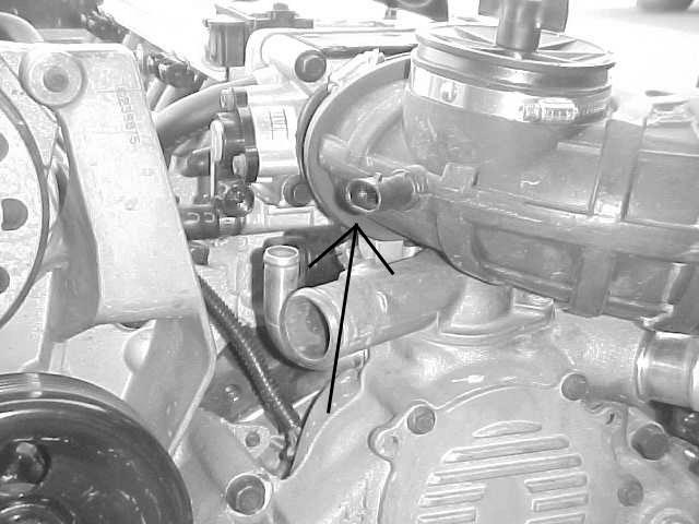
13 FIGURE 6.7 Air Pump Connection FIGURE 6.8 Fuel Pump Relay Connector 6.3 ENGINE GROUP INSTALLATION The engine group is designed to be separated into left side (driver) and right side (passenger) sections. Each side is tie-wrapped separately, BUT NOT LABELED. The right side of the engine has the connectors for the idle air control, throttle position sensor, distributor, and map sensor, all of which ARE labeled. When you begin routing, FIRST separate the engine group into left and right sections and place them accordingly Before you connect any wires, separate the tail section from the engine group and place it out of the way Locate the two Blk/Wht wires in the harness that end in a single, large ring terminal and ground them to the engine Using Figure , and the specific connections indicated in Table 6.1, connect the wiring as directed. NOTE: The air pump connector is rolled up in the dash section and must be routed out to the engine compartment if the air pump is to be operational. See section 4.1 Paragraph Check to make sure that the wire harness has the correct distributor connector on it for your particular engine. There are two different connectors used on LT1 engines. The 92 &93 engines used a short connector, 1" long and the 94 and up engines use a 2" connector. This harness has the 2" connector made on it. You may reuse the original connector or contact Painless Performance for a 1" pigtail connector The pink wire labeled coil power needs to be connected to the wire that powered the coil on the original engine. 9


14 6.3.6 Engine Section Connections WIRE COLOR # OF POSITIONS LABELED CONNECT TO: IN CONNECTOR Brown, Gray 2 EGR EGR Solenoid Blue 1 Knock Knock Sensor Purple/White, Tan/White, Brown, Black 4 Driver Side Oxy Left Oxygen Sensor Purple, Tan, Brown, Black 4 Pass. Side Oxy Right Oxygen Sensor Red Ring Terminal (2) Starter B+ Starter Solenoid Gray, Light Green, Black 3 MAP Map Sensor Pink, Black 2 Inj # 1 Drivers Side Front Inj Pink, Light Green/Black 2 Inj # 2 Pass Side Front Inj Pink, Pink/Black 2 Inj # 3 Drivers Side 2nd Inj Pink, Light Blue/Black 2 Inj # 4 Pass Side 2nd Inj Pink, Black/White 2 Inj # 5 Drivers Side 3rd Inj Pink, Yellow/Black 2 Inj # 6 Pass Side 3rd Inj Pink, Red/Black 2 Inj # 7 Drivers Side 4th Inj Pink, Blue/White 2 Inj # 8 Pass Side 4th Inj Gray, Black, Blue 3 TPS Throttle Position Sensor Light Green/Black, Light Green/White Light Blue/Black, Light Blue/White 4 IAC Idle Air Control Motor Yellow, Black/White, Pink 3 MAF Mass Airflow Sensor Red/Black, Pink/Black, Red, Light Blue/Black 4 DIST Distributor White, Black, Pink/Black, White/Black 4 IGN MOD Ignition Module Pink, White 2 Coil Ignition Coil Pink/Black, White/Black 2 Coil Ignition Coil Black, Yellow 2 ECT Engine Coolant Temp.Sensor Black, Tan 2 IAT Intake Air Temp Sensor Black, Black/White (3) Ring Terminal (2) Ground Engine Ground Pink Coil Power Power For Coil TABLE 6.2 Engine Section Connections FIGURE 6.9 EGR Solenoid FIGURE 6.10 Knock Sensor 10


15 FIGURE 6.11 Oxygen Sensor FIGURE 6.12 MAP Sensor FIGURE 6.13 Injectors 1, 3, 5, 7 FIGURE 6.14 Injectors 2, 4, 6, 8 FIGURE 6.15 TPS Sensor FIGURE 6.16 IAC 11


16 FIGURE 6.17 MAF Sensor FIGURE 6.18 Distributor i FIGURE 6.19 Ignition Module FIGURE 6.20 Coil FIGURE 6.21 ECT Sensor FIGURE 6.22 IAT Sensor 12

 and connect to the Vehicle Speed Sensor.")
17 6.4 TAIL SECTION INSTALLATION Locate the tail section that you earlier separated from the engine group. Begin routing it towards the rear of the vehicle. Be sure to avoid all sharp edges, moving or hot parts, or anything else that may damage the harness If you ARE using the 4L60E transmission, route the 13-position connector to the transmission and attach it If you ARE NOT using the 4L60E transmission, tape up the connector and store it in the harness Take the gray wire and route it to the fuel pump. This is the power wire for the fuel pump Take the connector for the Vehicle Speed Sensor (VSS) and connect to the Vehicle Speed Sensor Tail Section Connections WIRE COLOR # OF POSITIONS LABELED CONNECT TO: IN CONNECTOR Purple, Yellow 2 VSS Speed Sensor Gray Fuel Pump Fuel Pump Light Green, White, Light Blue/White, Tan/Black, Brown, Pink, Yellow/Black, Red/Black, Pink/Black, Blue, Red, Yellow/White, Black 13 Trans Transmission TABLE 6.3 Tail Section Connections FIGURE 6.23 VSS 7.0 TROUBLE- SHOOTING INSTRUCTIONS FIGURE 6.24 Transmission Connection If you are having trouble with your engine running badly or not running at all, first perform basic troubleshooting (ensure that you are using the correct parts (Table 4.1), check for faulty connections, blown fuses, connection of VATS module, spark, timing, fuel pressure, etc.), then see if the computer has stored a trouble code in its memory. 13
18 FIGURE 7.1 Fuse Identification 7.1 THE "CHECK ENGINE" LIGHT Normally, the "check engine" light should come on when the ignition is turned on, then go out a few moments after the engine starts running. If it reappears, or stays on while the engine is running, the computer has detected a problem and a trouble code has been set. 7.2 RETRIEVING TROUBLE CODES FROM THE COMPUTER The chart below shows the type of ALDL test connector each vehicle came with from the factory. If you are using a computer with 94 Camaro/Firebird, Caprice or 95 Impala programming you must obtain a OBD 1 connector. We will provide this connector at no charge by calling our tech line at Ask for part number WH Camaro OBD 1 OBD 11 OBD 11 Firebird OBD 1 OBD 11 OBD 11 Caprice OBD 1 OBD 1 OBD 11 Impala OBD 1 OBD In order to retrieve the trouble codes stored in the computer, a scanner must be connected to the Assembly Diagnostic Link (DLC) connector (installed and connected in Paragraph 6.2.1). Follow the instructions provided with the scanner to read the codes set in the computer After you have read any codes, write them down for reference. Remove the connector from the DLC connector Take the codes one at a time and match them to the codes in Table7.1. This will tell you in which circuit the computer has detected a problem. Note: A code indicates a problem in a specific circuit, NOT THAT A PARTICULAR PART IS BAD Before taking more extensive corrective actions for any trouble codes, make sure that all connections on the indicated circuit, INCLUDING THE COMPUTER, are clean and tight. Inspect the wiring in the circuit for any broken, shorted, or exposed wires. Finally, insure all ground wires are clean and secure If a trouble code is detected and the problem has been fixed, clear the codes by first making sure the ignition is off then disconnecting the NEGATIVE battery cable for at least 3 minutes. 14
19 7.2.6 Trouble Code Chart, Diagnostic Trouble Code (DTC) DTC 11 = Malfunction Indicator Lamp DTC 13 = Bank 1 (left) Heated Oxygen Sensor (HO2S) Open Circuit DTC 14 = Engine Coolant Temperature (ETC) Sensor Circuit (Signal Voltage Low) Overheated DTC 15 = Engine Coolant Temperature (ETC) Sensor Circuit (Signal Voltage High) Engine cold DTC 16 = Distributor Ignition System (Low Resolution Pulse) DTC 18 = Injector Circuits DTC 21 = Throttle Position (TP) Sensor Circuit (Signal Voltage High) DTC 22 = Throttle Position (TP) Sensor Circuit (Signal Voltage Low) DTC 23 = Intake Air Temperature (IAT) Sensor Circuit (Signal Voltage High) Cold Intake Air DTC 24 = Vehicle Speed Sensor (VSS) Circuit DTC 25 = Intake Air Temperature (IAT) Sensor Circuit (Signal Voltage Low) Hot Intake Air DTC 26 = Evaporative Emission (EVAP) Canister Purge Solenoid Valve Circuit DTC 27 = Exhaust Gas Recirculation (EGR) Vacuum Control Solenoid Valve Circuit DTC 28 = Transmission Range (TR) Pressure Switch Assembly Fault DTC 29 = Secondary Air Injection (AIR) Pump Circuit DTC 32 = Exhaust Gas Recirculation (EGR) DTC 33 = Manifold Absolute Pressure (MAP) Sensor Circuit (Signal Volts High, Low Vacuum) DTC 34 = Manifold Absolute Pressure (MAP) Sensor Circuit (Signal Volts Low, High Vacuum) DTC 36 = Distributor Ignition System (Faulty High or Extra Low Resolution Pulse Detected) DTC 37 = Brake Switch Stuck "ON" DTC 38 = Brake Switch Stuck "OFF" DTC 41 = Ignition Control (IC) Circuit (Open Circuit) DTC 42 = Ignition Control (IC) Circuit (Shorted or Grounded Circuit) DTC 43 = Knock Sensor (KS) Circuit DTC 44 = Bank 1 (Left) Heated Oxygen Sensor (HO2S) Circuit (Lean Exhaust Indicated) DTC 45 = Bank 1 (Left) Heated Oxygen Sensor (HO2S) Circuit (Rich Exhaust Indicated) DTC 46 = Pass-Key Circuit DTC 47 = Knock Sensor (KS) Module Circuit or Module Missing DTC 48 = Mass Air Flow (MAF) Sensor Circuit DTC 50 = System Voltage Low DTC 51 = EEPROM Programming Error DTC 53 = System Voltage High DTC 55 = Fuel Lean Monitor DTC 58 = Transmission Fluid Temperature (TFT) Sensor Circuit Low (High Temp Indicated) DTC 59 = Transmission Fluid Temperature (TFT) Sensor Circuit High (Low Temp Indicated) DTC 61 = A/C System Performance DTC 63 = Bank 2 (Right) Heated Oxygen Sensor (H02S) Circuit (Open Circuit) DTC 64 = Bank 2 (Right) Heated Oxygen Sensor (H02S) Circuit (Lean Exhaust Indicated) DTC 65 = Bank 2 (Right) Heated Oxygen Sensor (H02S) Circuit (Rich Exhaust Indicated) DTC 66 = A/C Refrigerant Pressure Sensor Circuit (Open or Shorted) DTC 67 = A/C Refrigerant Pressure Sensor Circuit (Pressure Sensor or A/C Clutch Problem) DTC 68 = A/C Relay Circuit (Shorted Circuit) DTC 69 = A/C Clutch Circuit DTC 70 = A/C Clutch Relay Driver Circuit DTC 71 = A/C Evaporator Temperature Sensor Circuit (Open or Shorted) DTC 72 = Vehicle Speed Sensor Loss (Automatic Transmissions Only) DTC 73 = Pressure Control Solenoid (PCS) Circuit (Current Error) DTC 74 = Traction Control Circuit (TCS) Circuit Low DTC 75 = Transmission System Voltage Low DTC 77 = Cooling Fan Relay Control Circuit DTC 79 = Transmission Fluid Overtemp DTC 81 = Transmission 2-3 Shift Solenoid Circuit DTC 82 = Transmission 1-2 Shift Solenoid Circuit 15
20 DTC 83 = Reverse Inhibit System (Manual Transmission) DTC 83 = TCC PWM Solenoid Circuit Fault (Automatic Transmission) DTC 84 = Automatic Transmission 3-2 Control Solenoid Circuit DTC 84 = Skip Shift Solenoid Circuit (Manual Transmission) DTC 85 = Transmission TCC Stuck "ON" DTC 90 = Transmission TCC Solenoid Circuit (Manual Transmission) DTC 91 = Skip Shift Lamp Circuit DTC 97 = VSS Output Circuit DTC 99 = Tach Output Circuit TABLE 7.1 Diagnostic Trouble Codes 7.3 WHEN TO CALL PAINLESS PERFORMANCE PRODUCTS' TECH LINE These harness kits have been built with the highest regard to quality control. Before calling us please double check all connections and perform normal basic trouble-shooting (fuel pressure, timing, ignition system, etc.) If you have any questions concerning the installation of this harness or having trouble in general, feel free to call Painless Performance Products' tech line at (817) Calls are answered from 8am to 5pm central time, Monday thru Friday, except holidays. questions to Tech@painlessperformance.com Painless Performance Limited Warranty and Return Policy Chassis harnesses, fuel injection harnesses, and Striker ColdShot units are covered under a lifetime warranty. All other products manufactured and/or sold by Painless Performance are warranted to the original purchaser to be free from defects in material and workmanship under normal use. Painless Performance will repair or replace defective products without charge during the first 12 months from the purchase date. No products will be considered for warranty without a copy of the purchase receipt showing the sellers name, address and date of purchase. You must return the product to the dealer you purchased it from to initiate warranty procedures. 16
Manual P/N Copyright Third Edition June 21, 2005
 P/N 60212, 60213, 60214 & 60215 1996-99 GM VORTEC WIRE HARNESS INSTALLATION INSTRUCTIONS Manual P/N 90524 Copyright 2003 Third Edition June 21, 2005 PAINLESS PERFORMANCE PRODUCTS 2501 Ludelle Street, Fort
P/N & GM LS1 FUEL INJECTION WIRE P/N & GM LS1 FUEL INJECTION WIRE HARNESS INSTALLATION INSTRUCTIONS
 P/N 60506 & 60507 1997-98 GM LS1 FUEL INJECTION WIRE HARNESS INSTALLATION INSTRUCTIONS P/N 60508 & 60509 1999-0 GM LS1 FUEL INJECTION WIRE HARNESS INSTALLATION INSTRUCTIONS Manual P/N 9050 Seventh Edition
SUM EFI Wiring Harness for GM LT-1/LT-4 Engine INSTALLATION INSTRUCTIONS
 SUM-890121 EFI Wiring Harness for GM LT-1/LT-4 Engine INSTALLATION INSTRUCTIONS INTRODUCTION This harness is designed for GM 1992-97 LT1/LT4 fuel injected engines. Even with minimal electrical experience,
P/N & GM LS1 w/mechanical (cable) THROTTLE BODY FUEL INJECTION WIRE HARNESS INSTALLATION INSTRUCTIONS
 THROTTLE BODY FUEL INJECTION WIRE HARNESS INSTALLATION INSTRUCTIONS") P/N 60508 & 60509 1997-0 GM LS1 w/mechanical (cable) THROTTLE BODY FUEL INJECTION WIRE HARNESS INSTALLATION INSTRUCTIONS Manual P/N 9050 Painless Performance Products, LLC 501 Ludelle Street Fort Worth,
P/N 60508 & 60509 1997-0 GM LS1 w/mechanical (cable) THROTTLE BODY FUEL INJECTION WIRE HARNESS INSTALLATION INSTRUCTIONS Manual P/N 9050 Painless Performance Products, LLC 501 Ludelle Street Fort Worth,
Wire Harness Installation Instructions
 Wire Harness Installation Instructions For Installing: Part #50001 Race Car Kit/8 Circuit Part #50201 8 Switch Dash Mounted Panel Part #50202 8 Switch Roll Bar Mounted Panel Manual #90502 Painless Performance
P/N & GM LS1 FUEL INJECTION WIRE HARNESS INSTALLATION INSTRUCTIONS
 P/N 605 & 6053 00-04 GM LS1 FUEL INJECTION WIRE HARNESS INSTALLATION INSTRUCTIONS Manual P/N 90544 nd Edition July 014 PAINLESS PERFORMANCE PRODUCTS 501 Ludelle Street - Fort Worth, Texas 76105-1036 -
Vortec Drive by Cable Electronic Fuel Injection Wiring Harness (P/N HAR-1018) HAR-1018
 HAR-1018") 1998 2002 Vortec Drive by Cable Electronic Fuel Injection Wiring Harness (P/N HAR-1018) HAR-1018 PERFORMANCE SYSTEMS INTEGRATION 170 Oberlin Ave N Suite 13 Lakewood NJ 08701-4548 Ph: 732-444-3277 Email:
1998 2002 Vortec Drive by Cable Electronic Fuel Injection Wiring Harness (P/N HAR-1018) HAR-1018 PERFORMANCE SYSTEMS INTEGRATION 170 Oberlin Ave N Suite 13 Lakewood NJ 08701-4548 Ph: 732-444-3277 Email:
'05- 'Current LS2/LS3 Drive by Cable Electronic Fuel Injection Wiring Harness HAR-1058
 '05- 'Current LS2/LS3 Drive by Cable Electronic Fuel Injection Wiring Harness HAR-1058 PERFORMANCE SYSTEMS INTEGRATION 170 Oberlin Ave N Suite 13 Lakewood NJ 08701-4548 Ph: 732-444-3277 Email: INFO@PSIConversion.com
P/N & GM LS2 FUEL INJECTION WIRE HARNESS INSTALLATION INSTRUCTIONS. Manual P/N 90543
 P/N 6050 & 6051 005-06 GM LS FUEL INJECTION WIRE HARNESS INSTALLATION INSTRUCTIONS Manual P/N 90543 1 Painless Performance Products, LLC 501 Ludelle Street Fort Worth, TX 76105-1036 800-43-9696 phone 817-44-404
GM VORTEC Drive by Wire Electronic Fuel Injection Wiring Harness HAR-1014
 GM VORTEC Drive by Wire Electronic Fuel Injection Wiring Harness HAR-1014 PERFORMANCE SYSTEMS INTEGRATION 170 Oberlin Ave N Suite 13 Lakewood NJ 08701-4548 Ph: 732-444-3277 Email: INFO@PSIConversion.com
SUM EFI Wiring Harness for GM LS1 Engine INSTALLATION INSTRUCTIONS
 SUM-890122 EFI Wiring Harness for GM LS1 Engine INSTALLATION INSTRUCTIONS 1 INTRODUCTION This harness is designed for GM 1997-2002 LS1 fuel injected engines utilizing a mechanical throttle body and throttle
VORTEC Drive by Wire Electronic Fuel Injection Wiring Harness HAR-1085
 2001 2002 VORTEC Drive by Wire Electronic Fuel Injection Wiring Harness HAR-1085 PERFORMANCE SYSTEMS INTEGRATION 170 Oberlin Ave N Suite 13 Lakewood NJ 08701-4548 Ph: 732-444-3277 Email: INFO@PSIConversion.com
P/N & GM VORTEC FUEL INJECTION 4.8L, 5.3L & 6.0L WIRE HARNESS INSTALLATION INSTRUCTIONS
 P/N 6017 & 6018 1999-00 GM VORTEC FUEL INJECTION 4.8L, 5.3L & 6.0L WIRE HARNESS INSTALLATION INSTRUCTIONS Manual P/N 90530 Second Edition November 004 Copyright November 004 PAINLESS PERFORMANCE PRODUCTS
PERFORMANCE SYSTEMS INTEGRATION
 2006 Current GEN IV LSX/Vortec 4.8, 5.3, 6.0, 6.2, 7.0 Drive by Wire (58X) Electronic Fuel Injection Wiring Harness w/ Manual or Non- Electronic Automatic Transmission HAR-10 (See Below) (P/N HAR- 1035,
Wire Harness Installation Instructions
 Wire Harness Installation Instructions For Installing: Part #60101 - GM 86-93 TBI Standard Harness & Part #60201 GM 86-93 TBI Extended Length Harness Manual # 90503 Painless Performance Products, LLC 2501
P/N GM VORTEC THROTTLE BY WIRE FUEL INJECTION 4.8L, 5.3L & 6.0L WIRE HARNESS INSTALLATION INSTRUCTIONS
 P/N 60221 2003-2006 GM VORTEC THROTTLE BY WIRE FUEL INJECTION 4.8L, 5.3L & 6.0L WIRE HARNESS INSTALLATION INSTRUCTIONS Manual P/N 90570 FIRST EDITION September 2009 Copyright SEPTEMBER 2009 PAINLESS PERFORMANCE
Perfect Performance Products, LLC Painless Performance Products Division 2501 Ludelle St. Fort Worth, Texas (800)
") Wire Harness Installation Instructions For Installing: Part # 65104 Into 1985-1992 (5.0 & 5.7L) TPI Engines Manual # 90536 Perfect Performance Products, LLC Painless Performance Products Division 2501
Wire Harness Installation Instructions For Installing: Part # 65104 Into 1985-1992 (5.0 & 5.7L) TPI Engines Manual # 90536 Perfect Performance Products, LLC Painless Performance Products Division 2501
Trail Rocker Installation Instructions
 Trail Rocker Installation Instructions Manual #90580 For Installing Painless Part Numbers: 57000 and 57001 Painless Performance Products recommends you, the installer, read this installation manual from
Off-Road Switch Panel Installation Instructions
 Off-Road Switch Panel Installation Instructions 50330: Off-road 4 Toggle switches/dash Mount w/keyed Ignition Switch 50332: Off-road 6 Toggle switches/dash Mount w/keyed Ignition Switch Painless Performance
Wire Harness Installation Instructions
 Wire Harness Installation Instructions For Installing: Part #60102 - GM 86-89 TPI Mass Air Flow (MAF) Standard Harness Part #60103 - GM 90-92 TPI w/speed Density (MAP) Standard Harness Part #60202 - GM
Trail Rocker Installation Instructions
 Trail Rocker Installation Instructions Manual #90581 For Installing Painless Part Numbers: 57002 Painless Performance Products recommends you, the installer, read this installation manual from front to
Wire Harness Installation Instructions
 Wire Harness Installation Instructions For Installing: Part #60102 - GM 86-89 TPI Mass Air Flow (MAF) Standard Harness Part #60103 - GM 90-92 TPI w/speed Density (MAP) Standard Harness Part #60202 - GM
Installation Instructions. Part #65100
 Installation Instructions Part #65100 Perfect Performance Products, LLC Painless Performance Products Division 2501 Ludelle Street Fort Worth, TX 76105-1036 800-423-9696 phone 817-244-4024 fax Web Site:
Installation Instructions
 Installation Instructions Part #40120 Perfect Performance Products, LLC Painless Performance Products Division 2501 Ludelle Street Fort Worth, TX 76105-1036 800-423-9696 phone 817-244-4024 fax Web Site:
Track Rocker Installation Instructions
 Track Rocker Installation Instructions For Installing Painless Part Numbers: 58103: 8-Switch Customizable Track Rocker Switch Panel w/ Flanged Mount 58106: 6-Switch Customizable Track Rocker Switch Panel
LSx Harness Installation. lsxeverything.com #BecauseYouShould
 LSx Harness Installation lsxeverything.com #BecauseYouShould Table of Contents Slide 1 Introduction Page Slide 2 Table of Contents Slide 3 Starting Instructions Slide 4 Power Connections Slide 5 Ground
Trail Rocker Installation
 Trail Rocker Installation Instructions Customizable Trail Rocker Control System For Installing Painless Part Number: 57100 Manual #90616 Painless Performance Products recommends you, the installer, read
TELORVEK II RJ-32 Big Block RamJet Fuel Injection System
 Page #1 TELORVEK II RJ-32 Big Block RamJet Fuel Injection System This wiring system is compatible with the GM Performance part big block Ramjet 502 engine. The harness is designed to dress up the appearance
TELORVEK III. WIRING INSTRUCTIONS FOR LT-40 LT-1 Fuel Injection System
 TELORVEK III WIRING INSTRUCTIONS FOR LT-40 LT-1 Fuel Injection System Page #1 Thank you for purchasing the absolute finest of wiring kits for the General Motors fuel injection. We have taken considerable
Perfect Performance Products, LLC Painless Performance Products Division 2501 Ludelle St. Fort Worth, Texas (800)
") PERFECT HI-VELOCITY 68MM THROTTLE BODY Installation Instructions Part # 65301 1991-1998 Jeep 4.0L Engines w/perfect Engine Management System P/N 65140, 65141 OR All Jeep 4.0L Engines in Cherokee, Grand
PERFECT HI-VELOCITY 68MM THROTTLE BODY Installation Instructions Part # 65301 1991-1998 Jeep 4.0L Engines w/perfect Engine Management System P/N 65140, 65141 OR All Jeep 4.0L Engines in Cherokee, Grand
Perfect Performance Products, LLC Painless Performance Products Division 2501 Ludelle St. Fort Worth, Texas (800)
") PERFECT HI-VELOCITY 62MM THROTTLE BODY Installation Instructions Part # 65302 2005-2006 Jeep 4.0L All Jeep 4.0L Engines in Cherokee, Grand Cherokee, Wrangler and Rubicon. Perfect Performance Products,
PERFECT HI-VELOCITY 62MM THROTTLE BODY Installation Instructions Part # 65302 2005-2006 Jeep 4.0L All Jeep 4.0L Engines in Cherokee, Grand Cherokee, Wrangler and Rubicon. Perfect Performance Products,
Part # GM LS2, 3 & 7-95mm Throttle Body
 Part # 65303 2006-2011 GM LS2, 3 & 7-95mm Throttle Body Perfect Performance Products, LLC 2501 Ludelle St. Fort Worth, Texas 76105 (800) 423-9696 1 We are always concerned about any corrections or improvements
Diagnostic Trouble Code (DTC) List - Vehicle
 List - Vehicle") Document ID# 850406 2002 Pontiac Firebird Diagnostic Trouble Code (DTC) List - Vehicle DTC DTC 021 and/or 031 DTC 022 and/or 032 DTC 023 or 033 DTC 24/34 DTC 025 and/or 035 DTC 041 DTC 042 DTC 043 DTC
Document ID# 850406 2002 Pontiac Firebird Diagnostic Trouble Code (DTC) List - Vehicle DTC DTC 021 and/or 031 DTC 022 and/or 032 DTC 023 or 033 DTC 24/34 DTC 025 and/or 035 DTC 041 DTC 042 DTC 043 DTC
Installation Instructions For 50330, 50331, 50332, and Off Road Switch Panels
 Installation Instructions For 50330, 50331, 50332, and 50333 Off Road Switch Panels 2501 Ludelle Street Fort Worth, Texas 76105 817-244-6212 Phone 817-244-4024 Fax 888-350-6588 Sales 800-423-9696 Tech
PERFECT HI-VELOCITY 62MM THROTTLE BODY
 PERFECT HI-VELOCITY 62MM THROTTLE BODY Installation Instructions Part # 65300 1991-1998 Jeep 4.0L Engines OR All Jeep 4.0L Engines in Cherokee, Grand Cherokee and Wrangler 1991-2005 w/4 wire IAC ONLY.
Trail Rocker Installation
 Trail Rocker Installation Instructions 4, 6, or 8 - Switch Customizable Trail Rocker Switch Panel w/ Flanged Mount For Installing Painless Part Number: 57103, 57106, & 57109 Manual #90636 Painless Performance
TELORVEK TPI WIRING INSTRUCTIONS FOR TH-90 (95 CK TRUCK) 4.3,5.0,5.7,7.4 TBI Fuel Injection System W/4L60-E or 4L80-E Transmission
 4.3,5.0,5.7,7.4 TBI Fuel Injection System W/4L60-E or 4L80-E Transmission") Page #1 TELORVEK TPI WIRING INSTRUCTIONS FOR TH-90 (95 CK TRUCK) 4.3,5.0,5.7,7.4 TBI Fuel Injection System W/4L60-E or 4L80-E Transmission Thank you for purchasing the absolute finest of wiring kits for
Page #1 TELORVEK TPI WIRING INSTRUCTIONS FOR TH-90 (95 CK TRUCK) 4.3,5.0,5.7,7.4 TBI Fuel Injection System W/4L60-E or 4L80-E Transmission Thank you for purchasing the absolute finest of wiring kits for
TELORVEK III WIRING INSTRUCTIONS FOR NS-93A 4.6 NORTHSTAR Fuel Injection System
 Page #1 TELORVEK III WIRING INSTRUCTIONS FOR NS-93A 4.6 NORTHSTAR Fuel Injection System Thank you for purchasing the absolute finest of wiring kits for the General Motors fuel injection. We have taken
Wire Harness Installation Instructions
 Wire Harness Installation Instructions For Installing: Part #60510 & 60511 Ford 5.0L or 5.8L 1986-93 Wiring Harness Manual #90518 Perfect Performance Products, LLC Painless Performance Products Division
TELORVEK EFI 5.0 Coyote Sequential Fuel Injection System Part # CY-11
 Page #1 TELORVEK EFI 5.0 Coyote Sequential Fuel Injection System Part # CY-11 WIRING INSTRUCTIONS Thank you for purchasing the absolute finest of wiring kits for the Ford Motor Co. Coyote modular engine.
30107 & PACK & 6-PACK RELAY BANK
 30107 & 30108 2501 Ludelle Street Fort Worth, Texas 76105 817-244-6212 Phone 817-244-4024 Fax 888-350-6588 Sales 800-423-9696 Tech E-mail: painless@painlessperformance.com Web: www.painlessperformance.com
Installation Instructions For #64260 Striker FE Module GMC/Chevrolet Duramax LB7 Diesel Copyright
 Installation Instructions For #64260 Striker FE Module 2001-2004 GMC/Chevrolet Duramax LB7 Diesel 2 nd Edition August 2007 Copyright 2006 by Perfect Performance Products, LLC 2501 Ludelle Street Fort Worth,
Track Rocker Installation Instructions
 Track Rocker Installation Instructions Customizable Track Rocker Control System For Installing Painless Part Number: 58100 Track Rocker Relay Center Manual #90641 Painless Performance Products recommends
Perfect Performance Products, LLC Painless Performance Products Division 2501 Ludelle St. Fort Worth, Texas (800)
") Camshaft Installation Instructions For Installing: Part # 65206 1997-2004 (5.7L) LS-1 Engines Perfect Performance Products, LLC Painless Performance Products Division 2501 Ludelle St. Fort Worth, Texas
Camshaft Installation Instructions For Installing: Part # 65206 1997-2004 (5.7L) LS-1 Engines Perfect Performance Products, LLC Painless Performance Products Division 2501 Ludelle St. Fort Worth, Texas
PIMP Ford 5.0 Harness Installation Manual. Part Number: PM-75
 PIMP Ford 5.0 Harness Installation Manual Part Number: PM-75 Ron Francis Wiring 200 Keystone Rd Suite 1 Chester, PA 19013 800-292-1940 www.ronfrancis.com Pre-Installation Notes: This system is designed
Installation Instructions For #64066 Striker I Power Module Ford Powerstroke 6.0L Diesel Copyright
 Installation Instructions For #64066 Striker I Power Module 2003-2006 Ford Powerstroke 6.0L Diesel 2 nd Edition August 2007 Copyright 2006 by Perfect Performance Products, LLC 2501 Ludelle Street Fort
This is the layout of a typical harness form a TPI Camaro.
 TPI wiring harness, typical 1986-89: This is the layout of a typical harness form a 1986-88 TPI Camaro. (A) bulkhead conn. through firewall. (B) ecm conn. (C) jct. conn for fuel injectors and cooling fan.
Part Number: TDZ-75SD / BRONCO-75SD
 Ford 5.0 EFI Harness Installation Manual For Classic Fords & Mustangs and Early Broncos Part Number: TDZ-75SD / BRONCO-75SD Ron Francis Wiring & The Detail Zone 200 Keystone Rd. Chester, PA 19013 800-292-1940
Installation Instructions For #64060 Striker I Power Module GMC/Chevrolet Duramax LB7 Diesel
 2501 Ludelle Street Fort Worth, Texas 76105 817-244-6212 Phone 817-244-4024 Fax 888-350-6588 Sales 800-423-9696 Tech E-mail: painless@painlessperformance.com Web: www.painlessperformance.com Installation
Wire Harness Installation Instructions
 Wire Harness Installation Instructions For Installing: Part #60510 & 60511 Ford 5.0L 1986-93 Wiring Harness Manual #90518 Painless Performance Products, LLC 2501 Ludelle Street Fort Worth, TX 76105-1036
Trail Rocker Installation Instructions
 Trail Rocker Installation Instructions Trail Rocker - Genesis Bracket For Installing Painless Part Number: 57200 Manual # 90591 To be used with Painless Kit # s: 57000-57005 Painless Performance Products
TELORVEK TPI WIRING INSTRUCTIONS FOR TH-100 (96-99 Vortech) 4.3,5.0,5.7,7.4 Fuel Injection System W/4L60-E or 4L80-E Transmission
 4.3,5.0,5.7,7.4 Fuel Injection System W/4L60-E or 4L80-E Transmission") Page #1 TELORVEK TPI WIRING INSTRUCTIONS FOR TH-100 (96-99 Vortech) 4.3,5.0,5.7,7.4 Fuel Injection System W/4L60-E or 4L80-E Transmission Thank you for purchasing the absolute finest of wiring kits for
Page #1 TELORVEK TPI WIRING INSTRUCTIONS FOR TH-100 (96-99 Vortech) 4.3,5.0,5.7,7.4 Fuel Injection System W/4L60-E or 4L80-E Transmission Thank you for purchasing the absolute finest of wiring kits for
Installation Instructions For #64160 Striker II Power Module GMC/Chevrolet Duramax LB7 Diesel Copyright
 Installation Instructions For #64160 Striker II Power Module 2001-2004 GMC/Chevrolet Duramax LB7 Diesel 2 nd Edition August 2007 Copyright 2006 by Perfect Performance Products, LLC 2501 Ludelle Street
WIRE HARNESS INSTALLATION INSTRUCTIONS
 WIRE HARNESS INSTALLATION INSTRUCTIONS For Installing: #10206 Classic Plus Customizable GM Pickup Chassis Harness 1967-72 28 Circuit Manual #90510 PERFECT PERFORMANCE PRODUCTS, LLC Painless Performance
LB-47 TELORVEK TPI. WIRING INSTRUCTIONS FOR Olds / Aurora 4.0 V-8 ENGINE
 Page #1 LB-47 TELORVEK TPI WIRING INSTRUCTIONS FOR Olds / Aurora 4.0 V-8 ENGINE Thank you for purchasing the absolute finest of wiring kits for the General Motors fuel injection. We have taken considerable
Installation Instructions. Manual # For Installing: Part # Painless Gauge Controller
 Installation Instructions Manual #90579 For Installing: Part #60650- Painless Gauge Controller Perfect Performance Products, LLC Painless Performance Products Division 2501 Ludelle Street Fort Worth, TX
TELORVEK TPI WIRING INSTRUCTIONS FOR LS Camaro/Firebird LS-1 Fuel Injection System
 Page #1 TELORVEK TPI WIRING INSTRUCTIONS FOR LS-85 98 Camaro/Firebird LS-1 Fuel Injection System Thank you for purchasing the absolute finest of wiring kits for the General Motors fuel injection. We have
Installation Instructions For #64320 Striker Turbo Timer Module
 2501 Ludelle Street Fort Worth, Texas 76105 817-244-6212 Phone 817-244-4024 Fax 888-350-6588 Sales 800-423-9696 Tech E-mail: painless@painlessperformance.com Web: www.painlessperformance.com Installation
Telephone: Fax: VAT Registration No.:
 Telephone: Fax: VAT Registration No.: K143 AC compressor clutch relay X88 AC connector S63 AC refrigerant pressure switch S341 AC refrigerant triple pressure switch A16 Anti-lock braking system (ABS) control
Powertrain DTC Summaries EOBD
 Powertrain DTC Summaries Quick Reference Diagnostic Guide Jaguar X-TYPE 2.0 L 2002.25 Model Year Refer to page 2 for important information regarding the use of Powertrain DTC Summaries. Jaguar X-TYPE 2.0
HOWELL INSTALLATION MANUAL. Tuned Port Or LT-1 Fuel Injection Harness ( )
") HOWELL ENGINE DEVELOPMENTS, INC. FUEL INJECTION APPLICATIONS INSTALLATION MANUAL Tuned Port Or LT-1 Fuel Injection Harness (1985-1992) Howell Engine Developments, Inc. 6201 Industrial Way Marine City,
HOWELL ENGINE DEVELOPMENTS, INC. FUEL INJECTION APPLICATIONS INSTALLATION MANUAL Tuned Port Or LT-1 Fuel Injection Harness (1985-1992) Howell Engine Developments, Inc. 6201 Industrial Way Marine City,
90558 Installation Manual For # Cummins 5.9L Common Rail Diesel
 2501 Ludelle Street Fort Worth, Texas 76105 817-244-6212 Phone 817-244-4024 Fax 888-350-6588 Sales 800-423-9696 Tech E-mail: painless@painlessperformance.com Web: www.painlessperformance.com 90558 Installation
Wire Harness Installation Instructions
 Wire Harness Installation Instructions For Installing: #10127 Customizable Mopar Chassis Harness 21 Circuit Manual #90542 Painless Performance Products, LLC 2501 Ludelle Street Fort Worth, TX 76105-1036
TELORVEK IV Ford Turbo 2.3 Fuel Injection System (MG-60)
") Page #1 TELORVEK IV Ford Turbo 2.3 Fuel Injection System (MG-60) WIRING INSTRUCTIONS Thank you for purchasing the absolute finest of wiring kits for the Ford Motor Co. fuel injection. We have taken considerable
Page #1 TELORVEK IV Ford Turbo 2.3 Fuel Injection System (MG-60) WIRING INSTRUCTIONS Thank you for purchasing the absolute finest of wiring kits for the Ford Motor Co. fuel injection. We have taken considerable
Installation Instructions For 50340
 Installation Instructions For 50340 2501 Ludelle Street Fort Worth, Texas 76105 817-244-6212 Phone 817-244-4024 Fax 888-350-6588 Sales 800-423-9696 Tech E-mail: painless@painlessperformance.com Web: www.painlessperformance.com
Diagnostic Trouble Codes (continued) GM Specific Codes
 GM Specific Codes") 85 GM Specific Codes P11XX Fuel and Air Metering P1106 MAP Sensor Circuit Intermittent High Voltage P1107 MAP Sensor Circuit Intermittent Low Voltage P1108 BARO to MAP Signal Comparison Too High P1111
85 GM Specific Codes P11XX Fuel and Air Metering P1106 MAP Sensor Circuit Intermittent High Voltage P1107 MAP Sensor Circuit Intermittent Low Voltage P1108 BARO to MAP Signal Comparison Too High P1111
Troubleshooting Self-diagnostic Procedures
 Self-diagnostic Procedures I. When the Malfunction Indicator Lamp (MIL) has been reported on, do the following: 1. Connect the Service Check Connector terminals with a jumper wire as shown. (The 2P Service
Diagnostic Trouble Code (DTC) memory, checking and erasing
 memory, checking and erasing") Page 1 of 49 01-12 Diagnostic Trouble Code (DTC) memory, checking and erasing Check DTC Memory (function 02) - Connect VAS5051 tester Page 01-7 and select vehicle system "01 - Engine electronics". Engine
Page 1 of 49 01-12 Diagnostic Trouble Code (DTC) memory, checking and erasing Check DTC Memory (function 02) - Connect VAS5051 tester Page 01-7 and select vehicle system "01 - Engine electronics". Engine
200-4R TRANSMISSION LOCK-UP HARNESS INSTALLATION INSTRUCTIONS
 2501 Ludelle Street Fort Worth, Texas 76105 817-244-6212 Phone 817-244-4024 Fax 888-350-6588 Sales 800-423-9696 Tech E-mail: painless@painlessperformance.com Web: www.painlessperformance.com 60110 200-4R
Powertrain DTC Summaries EOBD
 Powertrain DTC Summaries Quick Reference Diagnostic Guide Jaguar S-TYPE V6, V8 N/A and V8 SC 2002.5 Model Year Refer to pages 2 9 for important information regarding the use of Powertrain DTC Summaries.
C6 Corvette DIC Codes
 C6 Corvette DIC Codes B0159 Outside Air Temp Sensor B2910 Steering Column Lock Password Incorrect B0164 Pass Compartment Temp Sensor B2981 Right Front Door Handle Switch B0174 Output Air Temp Sensor 1
TELORVEK EFI. 4S. S e. n s tem. a l Fue l I n j e cti
 Page #1 4.63 V &5 TELORVEK EFI. 4S /C S e q uen i t a l Fue l I n j e cti o n Sy s tem MG-05 / MG-05A WIRING INSTRUCTIONS Thank you for purchasing the absolute finest of wiring kits for the Ford Motor
Wire Harness Installation Instructions
 Wire Harness Installation Instructions For Installing: #10112 Classic Customizable Chevy P/U Harness 19 Circuit Manual #90519 Perfect Performance Products, LLC Painless Performance Products Division 2501
Engine management/transmission
 MAZDA Model: 323 (BG) 323 Estate 1,6/4x4 (BW) 323 (BA/BJ) 626/MX-6 626/Estate Xedos 6/9 MX-3/MX-5 Year: 1989-00 Engina code: BP, BP-DOHC, B3, B3E, B6, B6-SOHC, B6-DOHC, B6E,FP, FS, KF, KJ, KL K8, RF, RF-CX,
DO NOT adjust by-pass valve full-close screw. Adjustment is preset at factory.
 I - SYSTEM/COMPONENT TESTS Article Text 1993 Honda Prelude For Cadi Centre Nsk CA 95051 Copyright 1998 Mitchell Repair Information Company, LLC Sunday, July 08, 2001 11:31AM ARTICLE BEGINNING 1993 ENGINE
TELORVEK EFI 4.6 Sequential Fuel Injection System (MG-91A)
") Page #1 TELORVEK EFI 4.6 Sequential Fuel Injection System (MG-91A) WIRING INSTRUCTIONS Thank you for purchasing the absolute finest of wiring kits for the 1996-98 Ford Motor Co. 4.6 / COBRA fuel injection
Page #1 TELORVEK EFI 4.6 Sequential Fuel Injection System (MG-91A) WIRING INSTRUCTIONS Thank you for purchasing the absolute finest of wiring kits for the 1996-98 Ford Motor Co. 4.6 / COBRA fuel injection
Diagnostic Trouble Codes (continued) Ford Specific Codes
 Ford Specific Codes") 92 Ford Specific Codes P11XX Fuel and Air Metering P1000 OBD-II Monitor Drive Cycle Not Completed P1001 KOER Self-Test Not Completed, Test Aborted P1100 Mass Airflow MAF Sensor Intermittent P1101 Mass
92 Ford Specific Codes P11XX Fuel and Air Metering P1000 OBD-II Monitor Drive Cycle Not Completed P1001 KOER Self-Test Not Completed, Test Aborted P1100 Mass Airflow MAF Sensor Intermittent P1101 Mass
Generation III Stand Alone Engine Harness
 78 Rattler Curry Road, Columbia, KY 42728 Phone 1-888-467-4491 sales@bp-automotive.com www.bp-automotive.com Generation III Stand Alone Engine Harness Installation Guide At BP Automotive we take pride
jegs.com
 Contents Wiring Harness w/ Fuse Panel Installation Instructions Turn Signal Plug w/ Terminals 2 Headlight Plugs 3/4 Grommet 10 ¼ Terminals 4 Ring Terminals 10 Wire Ties Fusible Link 2 Screws & Nuts 2 Plastic
INSTALLATION INSTRUCTIONS
 INSTALLATION INSTRUCTIONS 2009 CORVETTE LS - 9 INSTALLATION INSTRUCTIONS FOR LS 9 The following instructions are intended as an aid to assist in harness installation. More in depth information can be obtained
TELORVEK EFI 4.6 Sequential Fuel Injection System MK-97A
 Page #1 TELORVEK EFI 4.6 Sequential Fuel Injection System MK-97A WIRING INSTRUCTIONS Thank you for purchasing the absolute finest of wiring kits for the Ford Motor Co. 4.6. This harness works with 1999
GM Enhanced Parameters
 GM Enhanced Parameters # of 4x Ref Pulses between CAM Counter # OF EGR ADAPTIVE LEARN MATRIX CELLS OUT OF RANGE High # OF EGR ADAPTIVE LEARN MATRIX CELLS OUT OF RANGE LOW 1-2 Adapt High Cell 1-2 Adapt
TELORVEK EFI. 4.6 Sequential Fuel Injection System (FT-95) WIRING INSTRUCTIONS
 WIRING INSTRUCTIONS") Page #1 TELORVEK EFI 4.6 Sequential Fuel Injection System (FT-95) WIRING INSTRUCTIONS Thank you for purchasing the absolute finest of wiring kits for the Ford Motor Co. 4.6 94-95 Thunderbird, Cougar fuel
Page #1 TELORVEK EFI 4.6 Sequential Fuel Injection System (FT-95) WIRING INSTRUCTIONS Thank you for purchasing the absolute finest of wiring kits for the Ford Motor Co. 4.6 94-95 Thunderbird, Cougar fuel
Five-digit error code First position: P - is for powertrain codes B - is for body codes C - is for chassis codes
 https://www.automotive-manuals.net Five-digit error code First position: P - is for powertrain codes B - is for body codes C - is for chassis codes The second position: 0 - the total for the OBD-II code
2002 ENGINE PERFORMANCE. Self-Diagnostics - RAV4. Before performing testing procedures, check for any related Technical Service Bulletins (TSBs).
.") 2002 ENGINE PERFORMANCE Self-Diagnostics - RAV4 INTRODUCTION NOTE: Before performing testing procedures, check for any related Technical Service Bulletins (TSBs). To properly diagnosis and repair this
2002 ENGINE PERFORMANCE Self-Diagnostics - RAV4 INTRODUCTION NOTE: Before performing testing procedures, check for any related Technical Service Bulletins (TSBs). To properly diagnosis and repair this
Powertrain DTC Summaries OBD II
 Powertrain DTC Summaries Quick Reference Diagnostic Guide Jaguar X-TYPE 2.5L and 3.0L 2002 Model Year Revised January, 2002: P0706, P0731, P0732, P0733, P0734, P0735, P0740, P1780 POSSIBLE CAUSES Revised
JACKAROO TIPS Understanding the MIL fault codes on a Jackaroo Turbo Diesel
 JACKAROO TIPS Understanding the MIL fault codes on a Jackaroo Turbo Diesel The Jackaroo, as with all vehicles intended to be supplied to the USA market, (as the Isuzu Trooper) is fitted with OnBoard Diagnostics
Diagnostic Trouble Code (DTC) table
 table") Page 1 of 40 01-19 Diagnostic Trouble Code (DTC) table Note: When malfunctions occur in monitored sensors or components, Diagnostic Trouble Codes (DTCs) are stored in DTC memory with a description of the
Page 1 of 40 01-19 Diagnostic Trouble Code (DTC) table Note: When malfunctions occur in monitored sensors or components, Diagnostic Trouble Codes (DTCs) are stored in DTC memory with a description of the
ENGINE 01 02A 1. Toc of SCT ON-BOARD DIAGNOSTIC [ENGINE. Toc of SCT 01 02A ON-BOARD DIAGNOSTIC [ENGINE CONTROL SYSTEM (ZM)] 01 02A
![ENGINE 01 02A 1. Toc of SCT ON-BOARD DIAGNOSTIC [ENGINE. Toc of SCT 01 02A ON-BOARD DIAGNOSTIC [ENGINE CONTROL SYSTEM (ZM)] 01 02A](/thumbs/90/103285807.jpg "ENGINE 01 02A 1. Toc of SCT ON-BOARD DIAGNOSTIC [ENGINE. Toc of SCT 01 02A ON-BOARD DIAGNOSTIC [ENGINE CONTROL SYSTEM (ZM)] 01 02A") ENGINE 01 SECTION Toc of SCT ON-BOARD DIAGNOSTIC [ENGINE CONTROL SYSTEM (ZM)]...01-02A ON-BOARD DIAGNOSTIC [ENGINE CONTROL SYSTEM (FS)]...01-02B ON-BOARD DIAGNOSTIC [CRUISE CONTROL SYSTEM].......01-02C
ENGINE 01 SECTION Toc of SCT ON-BOARD DIAGNOSTIC [ENGINE CONTROL SYSTEM (ZM)]...01-02A ON-BOARD DIAGNOSTIC [ENGINE CONTROL SYSTEM (FS)]...01-02B ON-BOARD DIAGNOSTIC [CRUISE CONTROL SYSTEM].......01-02C
WIRE HARNESS INSTALLATION INSTRUCTIONS
 WIRE HARNESS INSTALLATION INSTRUCTIONS For Installing: #10205 Classic Plus Customizable GM Pickup Chassis Harness 1973-87 27 Circuit Manual #90507 Painless Performance Products, LLC 2501 Ludelle Street
30140 F5 Dual Fan Controller
 30140 F5 Dual Fan Controller 1 2501 Ludelle Street Fort Worth, Texas 76105 817-244-6212 Phone 817-244-4024 Fax 888-350-6588 Sales 800-423-9696 Tech E-mail: painless@painlessperformance.com Web: www.painlessperformance.com
Service Bulletin. DTC Detection Item Associated Monitor
 Service Bulletin 03-010 Applies To: All OBD II equipped models except SLX March 29, 2003 OBD II DTCs and Their Associated Monitors This is a list of all DTCs for all OBD II models. No one model has all
Wire Harness Installation Instructions For Installing:
 Wire Harness Installation Instructions For Installing: #20106 Classic Plus Customizable Tri-Five Chevy Harness 28 Circuit #20107 Classic Customizable Tri-Five Chevy Harness 21 Circuit Manual #90553 Painless
G - TESTS W/CODES - 2.2L
 G - TESTS W/CODES - 2.2L 1994 Toyota Celica 1994 ENGINE PERFORMANCE Toyota 2.2L Self-Diagnostics Celica INTRODUCTION If no faults were found while performing F - BASIC TESTING, proceed with self-diagnostics.
For Troubleshooting of DTC related components, see chart on page INTAKE AIR BYPASS (IAB) HIGH CONTROL SOLENOID
 HIGH CONTROL SOLENOID") Index For Troubleshooting of DTC related components, see chart on page 11-53. '96-99 models: EXHAUST GAS RECIRCULATION (EGR) and LIFT MANIFOLD ABSOLUTE PRESSURE (MAP) INTAKE AIR BYPASS (IAB) HIGH page
Index For Troubleshooting of DTC related components, see chart on page 11-53. '96-99 models: EXHAUST GAS RECIRCULATION (EGR) and LIFT MANIFOLD ABSOLUTE PRESSURE (MAP) INTAKE AIR BYPASS (IAB) HIGH page
Designed for the Street Proven on the Track
 TDR Fuel and Timing Card Wiring Thank you for using our TDR Fuel and or Timing Cards (F/T). There are two options on how to wire the F/T cards. Our preferred method is to use our TDR Patch Harness as shown
01 02B ON-BOARD DIAGNOSTIC [ENGINE CONTROL SYSTEM (FS)]
![01 02B ON-BOARD DIAGNOSTIC [ENGINE CONTROL SYSTEM (FS)]](/thumbs/80/80600627.jpg "01 02B ON-BOARD DIAGNOSTIC [ENGINE CONTROL SYSTEM (FS)]") ON-BOARD DIAGNOSTIC [ENGINE CONTROL SYSTEM (FS)] CONTROL SYSTEM WIRING DIAGRAM [FS]............................ 2 CONTROL SYSTEM DEVICE AND CONTROL RELATIONSHIP CHART [FS]........ 4 Engine Control System............
ON-BOARD DIAGNOSTIC [ENGINE CONTROL SYSTEM (FS)] CONTROL SYSTEM WIRING DIAGRAM [FS]............................ 2 CONTROL SYSTEM DEVICE AND CONTROL RELATIONSHIP CHART [FS]........ 4 Engine Control System............
ARTICLE BEGINNING INTRODUCTION SELF-DIAGNOSTIC SYSTEM RETRIEVING DTCS ENGINE PERFORMANCE Volkswagen Self-Diagnostics - Gasoline
 Article Text ARTICLE BEGINNING 1996 ENGINE PERFORMANCE Volkswagen Self-Diagnostics - Gasoline Cabrio, Golf III, GTI, Jetta III, Passat INTRODUCTION If no faults were found while performing preliminary
HOWELL INSTALLATION MANUAL. Throttle Body Fuel Injection Harness
 HOWELL ENGINE DEVELOPMENTS, INC. FUEL INJECTION APPLICATIONS INSTALLATION MANUAL Throttle Body Fuel Injection Harness Howell Engine Developments, Inc. 6201 Industrial Way Marine City, MI 48039 Phone: 810-765-5100
Telephone: Fax: VAT Registration No.:
 Telephone: Fax: VAT Registration No.: Name: Manufacturer: Ford Address: Model: Year: 1994 Registration: Tel - Private: Tel - Business: Mileage: Job number: Terminal side Wire side Component/circuit description