Electrical Control System Components Basics of Magnetic Control :
|
|
|
- Jade Marshall
- 5 years ago
- Views:
Transcription
1 Electrical Control System Components Basics of Magnetic Control : Dr.M.S.Narkhede, LEE, GP Mumbai 1
2 Contact Types : Contacts are classified into different ways as follows. According to applications contacts are classified in two types. Power contacts (Main contacts) & Auxillary contacts. According to position contacts are classified as NO & NC i.e. normally open contact and normally closed contact. According to the characteristics of the load to be switched or controlled contacts are classified in various categories. e.g. The making and breaking current under resistance load corresponds to the continuous operational current while for squirrel-cage induction motors draws a variable current In order to make the choice of devices easier, utilization categories are defined for contacts, contactors, disconnectors, circuit breakers and load switches as IEC , -2, -3, -4, -5, -6.(International Electrotechnical Commission ) Examples of Categories : AC-20A, AC-20B - Connecting and disconnecting under noload conditions AC-21A, AC-21-B- Switching of resistive loads, including moderate overloads AC-22A, AC-22B - Switching of mixed resistive and inductive loads, including moderate overloads AC-23A, AC-23B - Switching of motor loads or other highly inductive loads AC-1 - Non-inductive or slightly inductive loads, resistance furnaces AC-2 - Slip-ring motors: starting, switching off AC-3 - Squirrel-cage motors: starting, switching off motors during running AC-4 - Squirrel-cage motors: starting, plugging1), inching2 Dr.M.S.Narkhede, LEE, GP Mumbai 2


3 Solenoids : A solenoid is a three-dimensional coil. In physics, the term solenoid refers to a loop of wire, often wrapped around a metallic core, which produces a magnetic field when an electric current is passed through it. Solenoids are important because they can create controlled magnetic fields and can be used as electromagnets. In engineering, the term solenoid may also refer to a variety of transducer devices that convert energy into linear motion. The term is also often used to refer to a solenoid valve, which is an integrated device containing an electromechanical solenoid which actuates either a pneumatic or hydraulic valve. According to supply given solenoids are classified as DC or AC. Dr.M.S.Narkhede, LEE, GP Mumbai 3


4 Input Devices : Switches / Push Buttons: A switch is an electrical component that can break the circuit. Switches are classified as SPST, SPDT,DPST,DPDT and so on. Dr.M.S.Narkhede, LEE, GP Mumbai 4


5 PUSH BUTTON It is a pilot device which provides control of an equipment by pressing an actuator. A spring returned momentary contact push button is shown in figure. The contact block has two contacts one NO and another NC. When push button is pressed NC contact opens and NO contact closes. Foot Switch These switches are operated by foot. These are also pilot devices Generally they rest on ground. The applications are in Lathes, Agriculture etc. Dr.M.S.Narkhede, LEE, GP Mumbai 5

6 Selector switch Selector switches are actuated with a rotary knob or lever of some sort to select one of two or more positions. Like the toggle switch, selector switches can either rest in any of their positions or contain spring-return mechanisms for momentary operation. Dr.M.S.Narkhede, LEE, GP Mumbai 6

7 Proximity switch Proximity switches sense the approach of a metallic machine part either by a magnetic or highfrequency electromagnetic field. Simple proximity switches use a permanent magnet to actuate a mechanism whenever the machine part gets close. More complex proximity switches work like a metal detector, energizing a coil of wire with a high-frequency current, and electronically monitoring the magnitude of that current. If a metallic part (not necessarily magnetic) gets close enough to the coil, the current will increase, and trip the monitoring circuit. Photo Electric switch A photoelectric switch is a device used to detect the distance, absence, or presence of an object by using a light transmitter, often infrared, and a photoelectric receiver. They are used extensively in industrial manufacturing. There are three different functional types: opposed (through beam), retroreflective proximity-sensing Dr.M.S.Narkhede, LEE, GP Mumbai 7


8 Temperature actuated switch Normal operating range is 60 to F. Normally contact is closed. When temperature of probe is reached to set value contact opens Temperature switches or thermostats are used for maintaining a prescribed value of temperature during the process in industry. There are two types of temperature switches used in industry First one used bimetallic strip type which works in a similar way to that of an overload relay. The accuracy is not high. The second one uses a liquid or gas or vapour as the sensing element in a short length of pipe or thin tube called as capillary tube with bulb at one end. The expansion of the liquid, gas, vapor is utilized to actuate the switch contact. The temperature ranges are as follows Liquid filled 37 0 C to C Gas filled 37 0 C to C Vapour filled 10 0 C to C Dr.M.S.Narkhede, LEE, GP Mumbai 8
9 Level Control Switch Dr.M.S.Narkhede, LEE, GP Mumbai 9

10 The Float switch shown in the figure is used to maintain liquid levels within a certain range in a tank by energizing a pump when a liquid level falls to a certain lower pre set height and by de-energizing the pump when liquid level rises above a certain higher pre set height. A floating object can be used to actuate a switch mechanism when the liquid level in an tank rises past a certain point. If the liquid is electrically conductive, the liquid itself can be used as a conductor to bridge between two electrodes Level switches can also be designed to detect the level of solid materials such as wood chips, grain, coal, or animal feed in a storage silo, bin, or hopper. Dr.M.S.Narkhede, LEE, GP Mumbai 10

11 A common design uses a "tuning fork" shaped metal prong, inserted into the bin from the outside at the desired height. The fork is vibrated at its resonant frequency by an electronic circuit and magnet/ electromagnet coil assembly. When the bin fills to that height, the solid material dampens the vibration of the fork, the change in vibration amplitude and/or frequency detected by the electronic circuit. Pressure Switch A Pressure switch is a form of switch that makes electrical contact when a certain set pressure has been reached on its input. This is used to provide on/off switching from a pneumatic or hydraulic source. The switch may be designed to make contact either on pressure rise or on pressure fall. Dr.M.S.Narkhede, LEE, GP Mumbai 11
12 Pressure switches are used in control systems to sense pressure of gas, air or liquid and feed signal to electrical circuit. Pressure switch can have NO or NC or both contacts. It can use Bellow or diaphragm or tube of semicircular shape to sense the pressure. Applications : In Pneumatics : switching off an electrically driven compressor when a set pressure is achieved in the reservoir In Hydraulics : To switch on a warning light if engine oil pressure falls below a safe level To switch on brake lights automatically by detecting a rise in pressure in hydraulic brake pipes In dust control systems (bag filter), a pressure switch is mounted on the header which will raise an alarm when air pressure in the header is less than necessary to gain or decline energy beyond the set value Dr.M.S.Narkhede, LEE, GP Mumbai 12
13 Relays Control relays are similar in construction to contactor. They accept the information from some sensing device and feed it to control circuit. The sensing devices used in conjunction with the relays are known as pilot devices. Pilot devices sense the variables like current, voltage, overload, frequency, temperature, pressure and many other. Relays are also used to multiply the contacts available on the pilot devices like pressure switches, level switches etc. With the help of relays the interlocking wiring is possible which removes the complexity in the circuit Dr.M.S.Narkhede, LEE, GP Mumbai 13
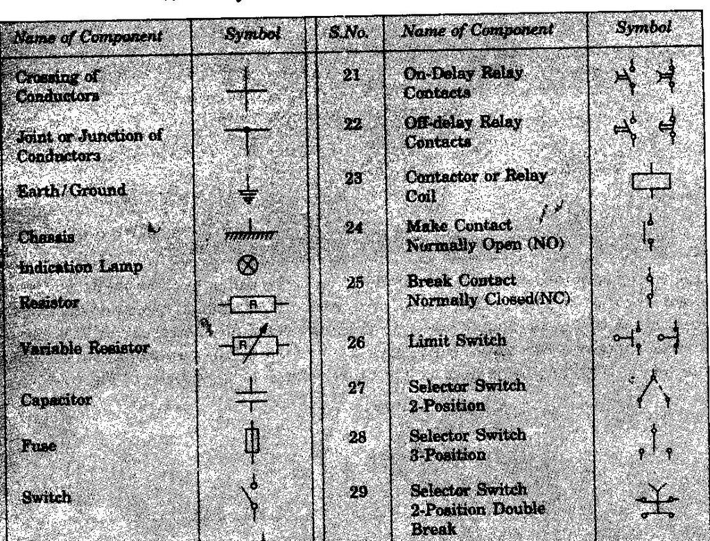
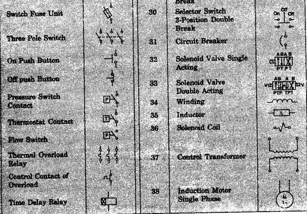
14 Symbols Dr.M.S.Narkhede, LEE, GP Mumbai 14

15 Developing Control Circuit: Basics & Thumb rule All control components like contactors, relays, push buttons etc. are designated by alphabets. For example In a forward and reverse operation of motor there are two contactors. Forward contactor is designated as F and reverse contactor is designated as R. All contacts of various contactors, relays shown in the diagram are in de energized state. The various contacts of contactor are designated by numerals. For example various contacts of a contactor F will be represented as F 1, F 2, F 3 and so on. The control wires are also designated with numbers in the diagram. These numbers are marked on wires by inserting ferrules on the wires. Dr.M.S.Narkhede, LEE, GP Mumbai 15
16 The thumb rule is to mark two supply leads of control transformer as L 1 and L 2. Here L 1 acts as phase supply and L 2 is generally grounded. The control diagrams are classified in to following 3 types. Wiring Diagram Elementary line diagram or schematic diagram Wireless connection diagram In wiring diagram the components are shown exactly according to their physical relationship and location in the panel. In schematic diagram representation of circuit is done in proper electrical sequence. In wireless connection diagram only location of components is shown. It is not used frequently. Dr.M.S.Narkhede, LEE, GP Mumbai 16
17 Dr.M.S.Narkhede, LEE, GP Mumbai 17
18 Control Circuit for Skip Hoist The figure shows the working of skip hoist. Dr.M.S.Narkhede, LEE, GP Mumbai 18
19 Overhead Crane Dr.M.S.Narkhede, LEE, GP Mumbai 19
20 Power circuit of Crane Dr.M.S.Narkhede, LEE, GP Mumbai 20
21 Conveyer Dr.M.S.Narkhede, LEE, GP Mumbai 21
22 Control circuit for conveyers Dr.M.S.Narkhede, LEE, GP Mumbai 22
23 A cam for operating conveyer circuit automatically Control Transformer Control Transformers are to supply power to control and / or auxiliary equipment not intended for direct connection to the main source. Control Transformers are specifically used to provide control supply voltage for the control circuits of AC motor starters, i.e. Starter coils, timers, indicating lamps electronics protection relays etc. Control Transformers for contractor applications have to Energize the coil and Maintain a contact for definite period of time. The initial energizing of the coil takes 5 to 40 mil. seconds and requires 3 to 10 times the normal current. While calculating the VA rating of the Control transformer, this factor should be taken in to account. They are available for single phase and three phase inputs and are in the range from 15 VA to 30 KVA. Dr.M.S.Narkhede, LEE, GP Mumbai 23

24 Control Transformer Control Transformers are to supply power to control and / or auxiliary equipment not intended for direct connection to the main source. Control Transformers are specifically used to provide control supply voltage for the control circuits of AC motor starters, i.e. Starter coils, timers, indicating lamps electronics protection relays etc. Control Transformers for contractor applications have to Energize the coil and Maintain a contact for definite period of time. The initial energizing of the coil takes 5 to 40 mil. seconds and requires 3 to 10 times the normal current. While calculating the VA rating of the Control transformer, this factor should be taken in to account. They are available for single phase and three phase inputs and are in the range from 15 VA to 30 KVA. Control Transformer Construction Control Transformers are two winding transformers with both windings made of copper. Power House transformers are made of using high quality materials. Electrolytic grade super enameled wire with best insulations are used. Core material are CRGO EI or Strip cores. Appropriate class of insulation materials are used. Transformers are impregnated in insulating varnish for long lasting performance. Input and out are terminated on Bakelite board with proper size of terminals. Dr.M.S.Narkhede, LEE, GP Mumbai 24
25 Control Transformer Information required while ordering: A) Input supply- Voltage, Frequency and Number of Phases i.e. Single or Three Phases. In case of Three Phase system Type of connection- Star / Delta / Vector group. B) Out put supply- voltage and current in of each secondary winding( if multiple out put windings are required). C) Class of insulations: D) Service conditions if other than standard service conditions. Dr.M.S.Narkhede, LEE, GP Mumbai 25
Programmable Logic Controller. Mat Nor Mohamad
 Programmable Logic Controller Mat Nor Mohamad Relays Electromagnetic Control Relays The PLC's original purpose was the replacement of electromagnetic relays with a solid-state switching system that could
Ch 4 Motor Control Devices
 Ch 4 Motor Control Devices Part 1 Manually Operated Switches 1. List three examples of primary motor control devices. (P 66) Answer: Motor contactor, starter, and controller or anything that control the
MOTOR TERMINAL CONNECTIONS
 MOTOR TERMINAL CONNECTIONS Motor Classification Most of the industrial machines in use today are driven by electric motors Motors are classified according to the type of power used (AC or DC) and the motors
Types of Motor Starters There are several types of motor starters. However, the two most basic types of these electrical devices are:
 Introduction Motor starters are one of the major inventions for motor control applications. As the name suggests, a starter is an electrical device which controls the electrical power for starting a motor.
Starting of Induction Motors
 1- Star Delta Starter The method achieved low starting current by first connecting the stator winding in star configuration, and then after the motor reaches a certain speed, throw switch changes the winding
ECET 211 Electric Machines & Controls Lecture 6 Contactors and Motor Starters. Lecture 6 Contactors and Motor Starters
 ECET 211 Electric Machines & Controls Lecture 6 Contactors and Motor Starters Text Book: Chapter 6, Electric Motors and Control Systems, by Frank D. Petruzella, published by McGraw Hill, 2015. Paul I-Hai
THE BEST ELECTRICAL CONTROLS BUSINESS ON THE PLANET! Unmatched Service Superior Product Quality Advantage Pricing
 Introduction A contactor is an electrical device which is used for switching an electrical circuit on or off. It is considered to be a special type of relay. However, the basic difference between the relay
Electrical Motor Controls Chapter 4 (Fourth Edition) Chapter 2 (Fifth Edition)
 Chapter 2 (Fifth Edition)") Electrical Motor Controls Chapter 4 (Fourth Edition) Chapter 2 (Fifth Edition) 1. Which drawing type shows physical details as seen by the eye? 2. Which drawing is similar to a pictorial drawing but has
Electrical Motor Controls Chapter 4 (Fourth Edition) Chapter 2 (Fifth Edition) 1. Which drawing type shows physical details as seen by the eye? 2. Which drawing is similar to a pictorial drawing but has
AF series contactors (9 2650)
") R E32527 R E39322 contactors General purpose and motor applications AF series contactors (9 2650) 3- & 4-pole contactors General purpose up to 2700 A Motor applications up to 50 hp, 900 kw NEMA Sizes 00
R E32527 R E39322 contactors General purpose and motor applications AF series contactors (9 2650) 3- & 4-pole contactors General purpose up to 2700 A Motor applications up to 50 hp, 900 kw NEMA Sizes 00
Module 2 CONTROL SYSTEM COMPONENTS. Lecture - 4 RELAYS
 1 Module 2 CONTROL SYSTEM COMPONENTS Lecture - 4 RELAYS Shameer A Koya Introduction Relays are generally used to accept information from some form of sensing device and convert it into proper power level,
MOTOR TERMINAL CONNECTIONS
 MOTOR TERMINAL CONNECTIONS Motor Classification Most of the industrial machines in use today are driven by electric motors Motors are classified according to the type of power used (AC or DC) and the motors
MECHATRONICS LAB MANUAL
 MECHATRONICS LAB MANUAL T.E.(Mechanical) Sem-VI Department of Mechanical Engineering SIESGST, Nerul, Navi Mumbai LIST OF EXPERIMENTS Expt. No. Title Page No. 1. Study of basic principles of sensing and
ECET 211 Electric Machines & Controls Lecture 4-1 Motor Control Devices: Lecture 4 Motor Control Devices
 ECET 211 Electric Machines & Controls Lecture 4-1 Motor Control Devices: Part 1. Manually Operated Switch Part 2. Mechanically Operated Switch Text Book: Electric Motors and Control Systems, by Frank D.
Direct On Line (DOL) Motor Starter. Direct Online Motor Starter
 Motor Starter. Direct Online Motor Starter") Direct On Line (DOL) Motor Starter Direct Online Motor Starter Different starting methods are employed for starting induction motors because Induction Motor draws more starting current during starting.
Direct On Line (DOL) Motor Starter Direct Online Motor Starter Different starting methods are employed for starting induction motors because Induction Motor draws more starting current during starting.
Electro - Hydraulics. & Pneumatics. Electro Hydraulic Press. Comparison. Electro Hydraulics. By: Alireza Safikhani
 Electro - 9 Hydraulics & Pneumatics 2 Electro Hydraulic Press The hydraulic press is controlled via the electrical control panel. Electrical signals are used to activate the valves in the hydraulic installation.
Approved Standards. Motor Contactor. Main contactor. Accessoires. 21 Motor Contactor J7KN
 Motor Contactor Main contactor AC & DC operated Integrated auxiliary contacts Screw fixing and snap fitting (35 mm DIN rail) up to 45 kw Range from 4 to 110 kw (AC 3, 380/415V) Finger proof ( VBG 4) Accessoires
The Contactor. Antonino Daviu, Jose Alfonso Departamento de Ingeniería Eléctrica. Universitat Politècnica de València
 The Contactor Surnames, name Antonino Daviu, Jose Alfonso (joanda@die.upv.es) Department Centre Departamento de Ingeniería Eléctrica Universitat Politècnica de València 1 1 Summary The aim of this paper
BELT-DRIVEN ALTERNATORS
 CHAPTER 13 BELT-DRIVEN ALTERNATORS INTRODUCTION A generator is a machine that converts mechanical energy into electrical energy using the principle of magnetic induction. This principle is based on the
DISCUSSION OF FUNDAMENTALS. A hydraulic system can be controlled either manually or automatically:
 Unit 1 Introduction to Electrical Control of Hydraulic Systems UNIT OBJECTIVE When you have completed this unit, you will be able to identify the components used for electrical control of the Hydraulics
Electrical Motor Controls (Fourth Edition)
") Electrical Motor Controls (Fourth Edition) 1. Which drawing type shows physical details as seen by the eye? Pictorial Drawing 2. Which drawing is similar to a pictorial drawing but has circles or rectangles
Electrical Motor Controls (Fourth Edition) 1. Which drawing type shows physical details as seen by the eye? Pictorial Drawing 2. Which drawing is similar to a pictorial drawing but has circles or rectangles
MAGNETIC MOTOR STARTERS
 Chapter 6 MAGNETIC MOTOR STARTERS 1 The basic use for the magnetic contactor is for switching power in resistance heating elements, lighting, magnetic brakes, or heavy industrial solenoids. Contactors
TRI-SERVICE ELECTRICAL WORKING GROUP (TSEWG) 03/05/09 TSEWG TP-11: UFC N BEST PRACTICES
 03/05/09 TSEWG TP-11: UFC N BEST PRACTICES") TSEWG TP-11: UFC 3-500-10N BEST PRACTICES UFC 3-500-10N was developed by NAVFAC and was used as the starting point for the tri-services development of UFC 3-500-10, Design: Electrical Engineering. UFC
TSEWG TP-11: UFC 3-500-10N BEST PRACTICES UFC 3-500-10N was developed by NAVFAC and was used as the starting point for the tri-services development of UFC 3-500-10, Design: Electrical Engineering. UFC
CHAPTER 8: ELECTROMAGNETISM
 CHAPTER 8: ELECTROMAGNETISM 8.1 Effect of a Magnet on a Current-carrying Conductor 8.1.1 Straight Wire Magnetic fields are circular Field is strongest close to the wire Increasing the current increases
SECTION MOTOR CONTROL
 SECTION 26 24 19 MOTOR CONTROL PART 1 - GENERAL 1.1 SECTION INCLUDES A. Manual motor starters B. Magnetic motor starters C. Combination magnetic motor starters D. Solid-state reduced voltage motor starters
MOTOR CONTROLLERS. STATE the function of motor controllers.
 Electrical Distribution Systems Motor controllers range from a simple toggle switch to a complex system using solenoids, relays, and timers. The basic functions of a motor controller are to control and
How to Select Automation Accessories for Valves
 How to Select Automation Accessories for Valves Today's process controls range from complete computer systems to the staffmonitored electromechanical type (push buttons, heavy-duty relays, etc.). In the
Industrial Automation Commonly-Used Terms
 Industrial Automation Commonly-Used Terms A Glossary of Industrial Automation and Control Terms LECINC.COM 1 A Accelerating Time: Across the Line Starter: Action Device: Actuator: Air (used as prefix):
Pretest Module 21 Units 1-4 AC Generators & Three-Phase Motors
 Pretest Module 21 Units 1-4 AC Generators & Three-Phase Motors 1. What are the two main parts of a three-phase motor? Stator and Rotor 2. Which part of a three-phase squirrel-cage induction motor is a
Technical Information
 C5 C5- C5- C5- C5- C5-550 ➊ 700 860 1000 1200 Rated Insulation Voltage U i to IEC 947-1 [V] 1000V 1000V 1000V 690V 690V UL/CS [V] 600V Rated Impulse Voltage U imp C5-550 / 700 / 860 [kv] 3.5 C5-1000 /
Adapted from presentation developed by Scott Fausneaucht
 Adapted from presentation developed by Scott Fausneaucht Definition of Electricity Electrical Fundamentals Generation & Transmission Transformers Fuses & Circuit Breakers Motors Motor Controls Safety Not
and Refrigeration Institute). CNX Special Purpose Contactors
. CNX Special Purpose Contactors") Series C7 Special Use Contactors Contactors designed and labeled for specific industrial applications Special Use Contactors Hydraulic elevator duty contactors HVC rated contactors Lighting contactors
Series C7 Special Use Contactors Contactors designed and labeled for specific industrial applications Special Use Contactors Hydraulic elevator duty contactors HVC rated contactors Lighting contactors
Chapter 8. Understanding the rules detailed in the National Electrical Code is critical to the proper installation of motor control circuits.
 Chapter 8 Understanding the rules detailed in the National Electrical Code is critical to the proper installation of motor control circuits. Article 430 of the NEC covers application and installation of
PATTERSON PUMP COMPANY
 PATTERSON PUMP COMPANY A Gorman Rupp Company JOCKEY PUMP CONTROLLERS UL508 LISTED ETL LISTED FEB 013 Patterson Jockey Pump controllers are built to NEMA industrial standards and are UL508 listed and ETL
Practical No: Aim: List out the tools required for Instrumentation Workshop and draw the diagram of any two tools
 Aim: List out the tools required for Instrumentation Workshop and draw the diagram of any two tools Tools : Equipment which can be used to repair, maintain and furnish the instruments that are known as
General + Definite Purpose Contactors
 General + Definite Purpose General Information... 2 Horse Power Rating Charts... 4 Contact Life... 8 Contactor Number Structure... Series C8 Miniature and Starters... 3 ccessories... 2 Contactor Cross
TECHNICAL SPECIFICATION
 TECHNICAL SPECIFICATION Star/delta starter Description: The electromagnetic starters LT 3 Dxx series are devices designed for remote control, direct control and protection of induction motors coiled and
Basics of Control Components
 Basics of Control Components Table of Contents Introduction...2 Electrical Symbols...6 Line Diagrams...16 Overload Protection...22 Overload Relays...26 Manual Control...35 Magnetic Contactors and Starters...41
PAC TRAINING PUMP MOTORS
 PAC TRAINING PUMP MOTORS 1 Basics Magnet supported from above N S N S Since unlike poles repel each other, the magnet will rotate Stationary Magnet 2 Basics N S Stationary Magnet 3 Basics N N S S Stationary
NHP SAFETY REFERENCE GUIDE
 4 NHP SAFETY REFERENCE GUIDE CONTENTS SAFETY TECHNOLOGY Risk Reduction Options Permanent Fixed Guard 4-02 Interlocked Guard: 4-03 Limit Switches 4-08 Presence Sensing Technology 4-09 Safety Laser Scanners
A Contactors. Technical Information. CA4 Miniature Contactors. Technical Information A94 CA4. Switching Motor Loads.
 C4 Miniature Contactors Contactors C4 Rated Insulation Voltage U i to IEC 947-1 [V] 500V UL/CS [V] 600V Rated Impulse Voltage U imp [kv] 8 Rated Voltage U e Main Contacts C 50/60Hz [V] 230, 240, 400, 415,
MODEL JH JACKSHAFT INDUSTRIAL DOOR OPERATOR INSTALLATION MANUAL. OPERATOR SPECIALTY COMPANY, INC. P.O. Box 128 Casnovia, MI 49318
 MODEL JH JACKSHAFT INDUSTRIAL DOOR OPERATOR INSTALLATION MANUAL OPERATOR SPECIALTY COMPANY, INC. P.O. Box 128 Casnovia, MI 49318 OSCO requires the use of a reversing edge or photoelectric control for pedestrian
TECHNICAL PAPER 1002 FT. WORTH, TEXAS REPORT X ORDER
 I. REFERENCE: 1 30 [1] Snow Engineering Co. Drawing 80504 Sheet 21, Hydraulic Schematic [2] Snow Engineering Co. Drawing 60445, Sheet 21 Control Logic Flow Chart [3] Snow Engineering Co. Drawing 80577,
STEP Motor Control Centers
 STEP 2000 Motor Control Centers Table of Contents Introduction...2 Motor Control...4 Power Supplies...8 Design Standards...13 Need for Circuit Protection...14 Overcurrent-Protection Devices...19 Motor
REVISIONS. App Thom. App Sud. App PC T.C. 2013/10/01
 REQUIREMENTS / REVISIONS Rev Description Rev n by Sud PC Thom VB LH Clyd Act Issue Date YYYY/MM/DD Standard Created T.C. 203/0/0 T.C. 203/0/0 Pending Pending Pending Pending Pending Pending 203/0/0 Sud
A few tips on how to select contactor for use in direct on line starter
 electrical-engineering-portal.com http://electrical-engineering-portal.com/contactors-direct-on-line-starters A few tips on how to select contactors for use in direct on line starters Google+ A few tips
Application Engineering
 Application Engineering February, 2009 Copeland Digital Compressor Controller Introduction The Digital Compressor Controller is the electronics interface between the Copeland Scroll Digital Compressor
THE ELECTRICAL CIRCUIT
 CHAPTER 20 THE ELECTRICAL CIRCUIT INTRODUCTION The basic items found in the ship s distribution have been presented. Power-consumers, such as motors and resistors, and those nonpower-consuming devices,
SECTION 4 ELECTRIC MOTORS UNIT 17: TYPES OF ELECTRIC MOTORS UNIT OBJECTIVES UNIT OBJECTIVES 3/21/2012
 SECTION 4 ELECTRIC MOTORS UNIT 17: TYPES OF ELECTRIC MOTORS UNIT OBJECTIVES After studying this unit, the reader should be able to Describe the different types of open single-phase motors used to drive
Application Note : Comparative Motor Technologies
 Application Note : Comparative Motor Technologies Air Motor and Cylinders Air Actuators use compressed air to move a piston for linear motion or turn a turbine for rotary motion. Responsiveness, speed
RAPIDMIX 400CW. Length of Machine (19.5m) Length when erected Width of Machine 9-10 (3.00 m) Width Same
 Length when erected Width of Machine 9-10 (3.00 m) Width Same") Machinery Manufacturers to the Concrete Industry RAPIDMIX 400CW The Rapidmix 400CW has been designed to be totally mobile and completely self-contained with its own power source. It is also completely
Machinery Manufacturers to the Concrete Industry RAPIDMIX 400CW The Rapidmix 400CW has been designed to be totally mobile and completely self-contained with its own power source. It is also completely
RELAYS. Figure Relay construction.
 RELAYS The RELAY is a device that acts upon the same fundamental principle as the solenoid. The difference between a relay and a solenoid is that a relay does not have a movable core (plunger) while the
IEC Utilization Categories (Explanation)
") IEC Utilization Categories (Explanation) IEC Utilization Categories Voltage Category Typical Applications A.C. A.C. and D.C. D.C. AC AC AC AC ACa ACb AC6a AC6b AC7a AC7b AC8a AC8b AC AC AC AC AC AC AC
IEC Utilization Categories (Explanation) IEC Utilization Categories Voltage Category Typical Applications A.C. A.C. and D.C. D.C. AC AC AC AC ACa ACb AC6a AC6b AC7a AC7b AC8a AC8b AC AC AC AC AC AC AC
2006 MINI Cooper S GENINFO Starting - Overview - MINI
 MINI STARTING SYSTEM * PLEASE READ THIS FIRST * 2002-07 GENINFO Starting - Overview - MINI For information on starter removal and installation, see the following articles. For Cooper, see STARTER WITH
Electrical Machines II. Week 5-6: Induction Motor Construction, theory of operation, rotating magnetic field and equivalent circuit
 Electrical Machines II Week 5-6: Induction Motor Construction, theory of operation, rotating magnetic field and equivalent circuit Asynchronous (Induction) Motor: industrial construction Two types of induction
INTERNATIONAL STANDARD
 INTERNATIONAL STANDARD IEC 60470 Second edition 1999-10 High-voltage alternating current contactors and contactor-based motor-starters Contacteurs pour courants alternatifs haute tension et démarreurs
10. Starting Method for Induction Motors
 10. Starting Method for Induction Motors A 3-phase induction motor is theoretically self starting. The stator of an induction motor consists of 3-phase windings, which when connected to a 3-phase supply
KD LV Motor Protection Relay
 1. Protection Features KD LV Motor Protection Relay Overload (for both cyclic and sustained overload conditions) Locked rotor by vectorial stall Running stall / jam Single phasing / Unbalance Earth leakage
Time delay relays. The following is a timing diagram of this relay contact's operation:
 Time delay relays Some relays are constructed with a kind of "shock absorber" mechanism attached to the armature which prevents immediate, full motion when the coil is either energized or de-energized.
Solstice Electric Fryers SE Series Service Manual
 Solstice Electric Fryers SE Series Service Manual L22-330 R1 (10/12) Notice In the event of problems or questions about your order, contact the Pitco Frialator factory at (603) 225-6684. In the event of
Exercise 1-5. Current Protection Devices EXERCISE OBJECTIVE DISCUSSION OUTLINE DISCUSSION. Circuit breakers
 Exercise 1-5 Current Protection Devices EXERCISE OBJECTIVE Describe and test the operation of circuit breakers, fuses, and overload relays. DISCUSSION OUTLINE The Discussion of this exercise covers the
Œ æ fl : GΔ»ÊflMmÈ A±È BMf æ fl MVÈ
 CCE RR UN-REVISED B O %lo ÆË v ÃO y Æ fio» flms ÿ,» fl Ê«fiÀ M, ÊMV fl 560 003 KARNATAKA SECONDARY EDUCATION EXAMINATION BOARD, MALLESWARAM, BANGALORE 560 003 G È.G È.G È.. Æ fioê, d È 2018 S. S. L. C.
Latch for Contactors 4-pole see page 36. Ratings Rated Aux. Contacts Type Coil voltage 2) AC2 Current Built-in Additional 24 24V= DC 5
 AC2 Current Built-in Additional 24 24V= DC 5") 3-pole DC Operated Ratings Rated Aux. Contacts Type Coil voltage 1) AC2 Current Built-in Additional 24 24V= DC 5 AC3 see 48 60V= DC 6 380V AC1 page 34 110 110V= DC 7 400V 660V 220 220V= DC 8 415V 690V
3-pole DC Operated Ratings Rated Aux. Contacts Type Coil voltage 1) AC2 Current Built-in Additional 24 24V= DC 5 AC3 see 48 60V= DC 6 380V AC1 page 34 110 110V= DC 7 400V 660V 220 220V= DC 8 415V 690V
Power Electronics. Motor brake relay GA 9031 ministop
 Power Electronics Motor brake relay GA 90 ministop 0 Thyristor electronic brake relay for motors up to kw Adjustable braking current up to 0 A Adjustable braking time Automatic standstill monitoring (optional)
CHAPTER 6 INTRODUCTION TO MOTORS AND GENERATORS
 CHAPTER 6 INTRODUCTION TO MOTORS AND GENERATORS Objective Describe the necessary conditions for motor and generator operation. Calculate the force on a conductor carrying current in the presence of the
CI-TI Contactors and motor starters Types CI 61 - CI 98
 Data sheet CI-TI Contactors and motor starters s CI 6 - CI 98 Contactors CI 6, CI 7, CI 86 and CI 98 switch powers of up to 0 kw, 7 kw, 45 kw and 55 kw respectively under 80 V - loads. Accessories include
[You may download this article at: https://fluidsys.org/downloads/ ]
![[You may download this article at: https://fluidsys.org/downloads/ ]](/thumbs/75/72588514.jpg "[You may download this article at: https://fluidsys.org/downloads/ ]") Fluidsys Training Centre, Bangalore offers an extensive range of skill-based and industry-relevant courses in the field of Pneumatics and Hydraulics. For more details, please visit the website: https://fluidsys.org
Fluidsys Training Centre, Bangalore offers an extensive range of skill-based and industry-relevant courses in the field of Pneumatics and Hydraulics. For more details, please visit the website: https://fluidsys.org
Electric Motor Controls BOMA Pre-Quiz
 Electric Motor Controls BOMA Pre-Quiz Name: 1. How does a U.P.S. (uninterruptable power supply) work? A. AC rectified to DC batteries then inverted to AC B. Batteries generate DC power C. Generator, batteries,
EE6351 ELECTRIC DRIVES AND CONTROL UNIT-1 INTRODUTION
 EE6351 ELECTRIC DRIVES AND CONTROL UNIT-1 INTRODUTION 1. What is meant by drive and electric drive? Machines employed for motion control are called drives and may employ any one of the prime movers for
Short Term Course On Hydropower Development Engineering (Electrical) for Teachers of Polytechnics in Uttarakhand L33-2
 for Teachers of Polytechnics in Uttarakhand L33-2") Short Term Course On Hydropower Development Engineering (Electrical) for Teachers of Polytechnics in Uttarakhand ( July 14-18, 2007) Lecture on L33-2 By S.N.Singh Senior Scientific officer ALTERNATE HYDRO
Short Term Course On Hydropower Development Engineering (Electrical) for Teachers of Polytechnics in Uttarakhand ( July 14-18, 2007) Lecture on L33-2 By S.N.Singh Senior Scientific officer ALTERNATE HYDRO
SECTION 3 BASIC AUTOMATIC CONTROLS UNIT 15 Troubleshooting Basic Controls
 SECTION 3 BASIC AUTOMATIC CONTROLS UNIT 15 Troubleshooting Basic Controls UNIT OBJECTIVES After studying this unit, the reader should be able to Describe and identify power- and non-power-consuming Describe
Manufacturing & Service: Bierer & Associates Inc. Patent No. 6,885,180. ST Series Service Tester Phase Identifier Operating Instructions ST500PGN
 Manufacturing & Service: Bierer & Associates Inc. Patent No. 6,885,180 ST Series Service Tester Phase Identifier Operating Instructions ST500PGN REV. ED. 101229 CONTENTS Limitation of Warranty and Liability
3.0 CHARACTERISTICS E Type CO-4 Step-Time Overcurrent Relay
 41-106E Type CO-4 Step-Time Overcurrent Relay A core screw accessible from the top of the switch provides the adjustable pickup range. The IIT contacts are connected in the trip circuit to trip instantaneously.
Starters. Overview. Siemens caters with following types of starters to agricultural and industrial sector.
 Starters Overview Siemens caters with following types of starters to agricultural and industrial sector. 55 Application The main purpose of motor starters is to start the electrical motor by switching
For system diagrams and component identification
 Pneumatic Symbols For system diagrams and component identification Contents Standards Actuators Basic symbols Valve symbol structure t Functional elements Flowlines Connections Conditioners and plant Pressure
Chandrashekar.p. Electrical and Electronics Engineering, PESITM-Shivamogga, Karnataka-India
 Protection and Control of Electrically Operated Over-Head Track Cranes (EOT) Using Multi-Functional Programmable Counter and Inductive Proximity Sensor. Chandrashekar.p Electrical and Electronics Engineering,
MAKING MODERN LIVING POSSIBLE. Technical brochure. Minicontactors CI 5-
 MKING MODERN LIVING POSSIBLE Technical brochure Minicontactors CI 5- www.danfoss.com 2 IC.PD.C10.F3.02-520B4167 Danfoss /S, C-SMC, mr, 07-2010 Contents Page Minicontactor CI 5- Introduction...............................................................................4
Industrial Control Transformers
 6 Industrial Control Transformers Section 6 Industrial Control Transformers provide a low and safe control voltage for the operation of electromagnetic devices, such as motor starters, contactors, solenoids
ADS7 AC Contactor Starters
 ADS7 AC Contactor Starters ADS7 starters fully comply with BS EN 60947-4-1, IEC 60947-4-1 and VDE 0660. The range offers a multitude of configurations and optional features including a complete choice
Materials can be classified 3 ways
 Magnetism Magnetism A magnet is an object that can attract other objects containing iron, cobalt, or nickel. Magnetic substances are created when electrons from within the atom or from another atom spins
three different ways, so it is important to be aware of how flow is to be specified
 Flow-control valves Flow-control valves include simple s to sophisticated closed-loop electrohydraulic valves that automatically adjust to variations in pressure and temperature. The purpose of flow control
INDUCTANCE FM CHAPTER 6
 CHAPTER 6 INDUCTANCE INTRODUCTION The study of inductance is a very challenging but rewarding segment of electricity. It is challenging because at first it seems that new concepts are being introduced.
Electric control panel
 Overview This electric control panel is used for UE and U type motor driven grease pump. It enables comfortable use of centralized lubricating system, and also plays a role in saving labor in a plant because
INTRODUCTION TO SENSORS, TRANSDUCERS & ACTUATORS
 INTRODUCTION Transducers play a major role in mechatronics engineering & technology. These are the basic elements that convert or transform one form of energy to another form. Let us change the word energy
Note 8. Electric Actuators
 Note 8 Electric Actuators Department of Mechanical Engineering, University Of Saskatchewan, 57 Campus Drive, Saskatoon, SK S7N 5A9, Canada 1 1. Introduction In a typical closed-loop, or feedback, control
AF09... AF30 3-pole Contactors up to 20 HP / 480 VAC
 AF0... AF0 -pole Contactors up to 20 HP / 480 VAC Contactors and Overload Relays Overview...2 AF0... AF0 -pole Contactors Ordering Details...4 Main Technical Data...20 DC Circuit switching...2 Main Accessory
2.1 Warnings & Agency Approvals Electrical Connections - Specifications Standard Wiring Configurations...2 4
 CHAPTER ELECTRICAL 2 INSTALLATION Contents of this Chapter... 2.1 Warnings & Agency Approvals..................2 2 2.1.1 Isolation..............................................2 2 2.1.2 Electrical Power
ELECTRICAL TECHNOLOGY 3 March 2008
 I. Course Description ELECTRICAL TECHNOLOGY 3 March 2008 The purpose for this course is to instruct potential electricians in the skills necessary for entry into the job market. During this course, the
Abbeon Cal, Inc. Model BD-50E HIGH FREQUENCY GENERATOR OPERATING MANUAL
 Abbeon Cal, Inc. Model BD-50E HIGH FREQUENCY GENERATOR OPERATING MANUAL DESCRIPTION. The Model BD-50E is a rugged tester designed for testing tank lining and other applications where extended use is necessary.
Model Number Legend. Motor Contactor J7KN. Motor Contactor J7KN 1
 Motor Contactor J7KN Range from 4 to 500 kw (AC 3, 380/415 V) AC and DC operated Integrated auxiliary contacts; integrated aux. contact of J7KN contactors up to 11kW suitable for electronic circuits Screw
Lecture Outline Chapter 23. Physics, 4 th Edition James S. Walker. Copyright 2010 Pearson Education, Inc.
 Lecture Outline Chapter 23 Physics, 4 th Edition James S. Walker Chapter 23 Magnetic Flux and Faraday s Law of Induction Units of Chapter 23 Induced Electromotive Force Magnetic Flux Faraday s Law of Induction
MINIATURE CIRCUIT BREAKER
 Technical Article MINIATURE CIRCUIT BREAKER T 146 PURCHASE he Spaceage MCB protects wires and cables automatically against overload and short-circuits in domestic, commercial and industrial installations.
Almost 200 years ago, Faraday looked for evidence that a magnetic field would induce an electric current with this apparatus:
 Chapter 21 Electromagnetic Induction and Faraday s Law Chapter 21 Induced EMF Faraday s Law of Induction; Lenz s Law EMF Induced in a Moving Conductor Changing Magnetic Flux Produces an E Field Inductance
EXPERIMENT 2 THREE PHASE INDUCTION MOTOR, PART 1
 University f Jordan School of Engineering Department of Mechatronics Engineering Electrical Machines Lab Eng. Osama Fuad Eng. Nazmi Ashour EXPERIMENT 2 THREE PHASE INDUCTION MOTOR, PART 1 OBJECTIVES To
Hazardous Factory Sealed Control Devices
 Hazardous Factory Sealed Control Devices Description Page No. Application/Selection 428, 429 Dimensions 40 Manual Motor Starting Switches & Enclosures EDS Series 440, 44 Pilot Lights EFS Series 45 Pilot
Reliably Switching Highest Currents up to 2000 A
 www.moeller.net Reliably Switching Highest Currents up to 2000 A The complete range for the motor circuit. From contactors to efficient motor-starters to controlled drives. New solutions that rely on communication.
Application Engineering
 Application Engineering March 2011 Copeland Digital Compressor Controller Introduction The Digital Compressor Controller is the electronics interface between the Copeland Scroll Digital compressor or the
Effective discrimination of protective devices
 Effective discrimination of protective devices In the event of a fault occurring on an electrical installation only the protective device nearest to the fault should operate,leaving other healthy circuits
1-3 MANUAL STARTERS EXERCISE OBJECTIVE. Examine and describe the operation of manual motor starters. DISCUSSION
 1-3 MANUAL STARTERS EXERCISE OBJECTIVE Examine and describe the operation of manual motor starters. DISCUSSION Motor starters are made out of power switches and overload protection devices. They can be
WARREN COUNTY, N.Y. M/E REFERENCE A. Submit manufacturer's product data on all motors and adjustable speed drives.
 SECTION 230513 - MOTORS AND ADJUSTABLE SPEED DRIVES PART 1 - GENERAL 1.1 DESCRIPTION A. Provide labor, materials, equipment and services as required for the complete installation designed in Contract Documents.