PARTS INCLUDED QTY PARTS INCLUDED QTY Winch 1 Roller Fairlead 1 Solenoid Box 1 Clevis Hook 1 Hardware Bag 1 Remote Control 1
|
|
|
- Cameron Burke
- 5 years ago
- Views:
Transcription
1 PARTS INCLUDED QTY PARTS INCLUDED QTY Winch 1 Roller Fairlead 1 Solenoid Box 1 Clevis Hook 1 Hardware Bag 1 Remote Control 1 SAFETY PRECAUTIONS Warning! Observe safety precautions for personal safety and the safety of others. Improper equipment operation may cause personal injury and equipment damage. Read the following carefully before attempting to operate your winch and keep the instructions for future reference. 1. Dress Properly: - Don t wear loose clothing or jewelry. They can be caught in moving parts. - Wear leather gloves when handling winch cable. Do not handle cable with bare hands as broken wires can cause injuries. - Non-skid footwear is recommended. - Protective hair covering to contain long hair. 2. Keep a Safe Distance: - Ensure that all persons stand well clear of winch cable and load during winch operation, 1.5 times the cable length recommended. If a cable pulls loose or breaks under load it can lash back and cause serious personal injury or death. - Don t step over the cable. - All visitors and onlookers should be kept away from the work area. - Keep proper footing and balance at all times. 3. Don t Abuse the Cord: - Never carry your winch by the cord or yank it to disconnect it from the receptacle. - Keep cord from heat, oil and sharp edges. 4. Don t Overwork the winch: - If the motor becomes uncomfortably hot to touch, stop and let it cool for a few minutes. - Don t maintain power to the winch if the motor stalls. - Don t exceed maximum line pull ratings shown in tables. Shock loads must not exceed these ratings. 5. Avoid Unintentional Starting: - Winch clutch should be disengaged when not in use and fully engaged when in use. 6. Check Damaged Parts: - Before using, you should check your winch carefully. Any part that is damaged should be properly repaired or replaced by an authorized service center. 7. Repair Your Winch: - When repairing, use only identical replacement parts or it may cause considerable danger to the user. 8. Re-spool the cable: - Leather gloves must be worn while re-spooling. To re-spool correctly, it is necessary to keep a slight load on the cable. Hold the cable with one hand and the remote control switch with the other. Start as far back and in the center as you can.walk up keeping load on the cable as the winch is powered in. - Do not allow the cable to slop through your hand and do not approach the winch too closely. - Turn off the winch and repeat the procedure until all the cable except 1m is left. - Disconnect the remote control switch and finish spooling in cable by rotating the drum by hand with clutch disengaged. - On hidden winches, spool in cable under power but keep hands clear. Page 2 of 33
2 Warning: The use of any other accessory or attachment other than those recommended in the Fitting Instructions may present a risk of personal injury. WINCH OPERATION WARNINGS Read the following carefully before attempting to operate your winch and keep the instructions for future reference. 1. The uneven spooling of cable, while pulling a load, is not a problem, unless there is a cable pile up on one end of the drum. If this happens reverse the winch to relieve the load and move your anchor point further to the center of the vehicle. After the job is done, you can un-spool and rewind for a neat lay of the cable. 2. Store the remote control switch inside your vehicle where it will not become damaged, inspect it before you plug it in. 3. When ready to begin spooling in, plug in remote control switch with clutch disengaged, do not engage clutch with motor running. 4. Never connect the hook back to the cable. This causes cable damage. Always use a sling or chain of suitable strength. 5. Observe your winch while winching, if possible while standing at a safe distance. Stop the winching process every meter or so to assure the cable is not piling up in one corner. Jamming the cable can break your winch. 6. Do not attach tow hooks to winch mounting apparatus. They must be attached to vehicle frame. 7. The use of a snatch block will aid recovery operations by providing a doubling of the winch capacity and a halving of the winching speed, and the means to maintain a direct line pull to the center of the rollers. When double loading during stationary winching, the winch hook should be attached to the chassis of the vehicle. 8. Ensure rated D or bow shackles are used in conjunction with an approved tree trunk protector to provide a safe anchor point. 9. When extending winch cable, ensure that at least FIVE (5) wraps of cable remain on drum at all times. Failure to do this could result in the cable parting from the drum under load. Serious personal injury or property damage may result. 10. All winches are provided with a Red Cable marking to identify that 5 cable wraps remain on the winch drum when this mark appears at the rollers. No recovery should be attempted beyond this marking. 11. Since the greatest pulling power is achieved on the innermost layer of your winch, it is desirable to pull off as much line as you can for heavy pulls (you must leave 5 wraps minimum on the drum-red cable). If this is not practical use a snatch block and double line arrangement. 12. Draping a heavy blanket or similar object over the extended winch cable is recommended as it will dampen any back lash should a failure occur. 13. Neat, tight spooling avoids cable blinding, which is caused when a load is applied and the cable is pinched between the others. If this happens, alternatively power the winch in and out. Do not attempt to work a bound cable under load, free by hand. 14. Apply blocks to wheels when vehicles are on an incline. 15. Battery: - Be sure that the battery is in good condition. Avoid contact with battery acid or other containments. - Always wear eye protection when working around a battery. - Have the engine running when using the winch, to avoid flattening the battery. 16. Winch cable: - Be sure that the cable is in good condition and is attached properly. - Do not use the winch if cable is frayed. - Do not move the vehicle to pull a load. Page 3 of 33
3 - - Do not replace the cable with a cable of lesser strength. - The life of cable is directly related to the use and care it receives. Following its first and subsequent uses, a cable must be wound onto the drum under a load of at least 500lbs (230kg) or the outer wraps will draw into the inner wraps and severely damage the cable during winching. The first winch use should be a familiar run while in a relaxed, non-recovery situation. Spool out the cable until the red cable mark appears (about five wraps on the drum), when rewind the cable onto the drum under a load of 500lbs (230kg) or more. This will slightly tension and stretch the new cable and create a tight cable wrap around the drum. Failure to do so may result in cable damage and reduced cable life. - When the cable is replaced, be sure to apply locktite, or the cable clamp thread. Tighten the clamp screw properly but do not over-tighten. The lockkite will prevent loosening of the screw in arduous conditions. Locktite 7471 primer and 222 Thread Locker are recommended. 17. Do not attempt to exceed the pulling limits of this winch. 18. Do not drive your vehicle to assist the winch in any way. Vehicle movement in combination with winch operation may overload the cable, the winch itself or cause damaging shock loads. 19. Shock loads when winching are dangerous! A shock load occurs when an increased force is suddenly applied to the cable. A vehicle rolling back on a slack cable may induce a damaging shock load. 20. The winches shown in this manual are solely for vehicle and boat mount, non-industrial applications. 21. Do not use winch in hoisting applications due to required hoist safety factors and features. 22. Do not use the winch to lift, support or otherwise transport personnel. 23. Do not move your winch by lifting the cable leads or the clutch handle lever. Page 4 of 33
4 INSTALLATION MOUNTING YOUR WINCH 1 a) The winch is to be mounted into a suitable steel mounting frame using the 4 point foot mounting system in either a horizontal or vertical plane. b) It is very important that the winch be mounted on a flat surface so that the three sections (motor, cable drum and gear housing) are properly aligned. c) Before commencing installation, ensure the mounting facility being used is capable of withstanding the rated capacity of the winch. d) The fitment of winches and / or a frontal protection system may affect the triggering of SRS air bags. Check that the mounting system has been tested and approved for winch fitment in the air bag equipped vehicle. 2. Smittybilt manufactures winch mounting frames and / or Frontal Protection Systems to suit most popular vehicles. Winch frames are packaged with detailed instructions. 3. Should you wish to manufacture your own mounting plate the dimensions below will assist. A steel mount plate of 6mm thickness is recommended. Fasteners should be steel high tensile grade 5 or better. A poorly designed mount may void warranty. 4. The winch should be secured to the mounting with 3/8 UNC* 1-1/4 steel bolts and spring washers provided. 5. The roller fairlead is to be mounted so as to guide the rope onto the drum evenly. 6. Special mounting requirements for XRC15. a) XRC15 is to be mounted into a suitable steel mounting frame using the 8 point foot mounting system in either a horizontal or vertical plane. b) A steel mount plate of 10 to 12mm thickness is recommended. Fasteners should be steel high tensile grade 8.8 or better (8 pieces grade 8.8 M12X40 fasteners are provided with the XRC15winch). Mounting Figure for XRC15 Page 5 of 33

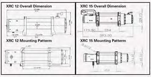
5 Page 6 of 33

6 LUBRICATION INSTALLATION All moving parts in the winch are permanently lubricated with high temperature lithium grease at the time of assembly. Under normal conditions factory lubrication will suffice. Lubricate cable periodically using light penetrating oil. Inspect for broken strands and replace if necessary. If the cable becomes worn or damaged, it must be replaced. CABLE INSTALLATION Unwind the new cable by rolling it along the ground, to prevent kinking. Remove old cable and observe the manner in which it is attached to the drum flange. ELETRICAL CONNECTION For normal self-recovery work, your existing electrical system is adequate. A fully changed battery and proper connections are essential. Run the vehicle engine during winching operations to keep charged. Pay close attention to proper electrical cable connection as follows (refer to Diagram 1) Be sure to observe the following steps for a correct and safe electrical connection: 1. Short Red cable (B ) connecting to the red terminal (B) of winch motor. 2. Short black cable with yellow jacket (C ) connecting to the yellow terminal (C) of the motor. 3. Short black cable with black jacket (D ) connecting to the black terminal (D) of the motor. 4. Thin black cable (A ) connecting to bottom terminal (A) of the motor. 5. Long black cable (1.8m), one terminal (a) connecting to the bottom terminal (A) of the motor, and the other terminal negative (-) connecting to negative (-) terminal of battery. 6. Long red cable positive (+) connecting to positive (+) of battery. Page 7 of 33
7 NOTE: 1. Your battery must be kept in good condition. 2. Be sure battery cables are not drawn taught across any surfaces, which could possibly damage them. 3. Corrosion on electrical connections will reduce performance or may cause a short. 4. Clean all connections especially in remote control switch and receptacle. 5. In salty environments use a silicone sealer to protect from corrosion. 6. Index the heads of the plate studs into the keyhole slots on the back of the winch. 7. Attached the winch/adaptor plate assembly to your trailer hitch, by inserting the trailer hitch ball through the shaped hole in the Adaptor plate. Page 8 of 33
8 WINCH OPERATION SUGGESTION: The best way to get acquainted with how your winch operates is to make a few test runs before you actually need to use it. Plan your test in advance. Remember you can hear your winch as well as you can see it operate. Get to recognize the sound of a light steady pull, a heavy pull, and sounds caused by load jerking or shifting. Soon you will gain confidence in operating your winch and its use will become second nature to you. OPERATING: 1. Ensure the vehicle is secured by applying the parking brake or chocking the wheels. 2. Pull out the winch cable the desired length and connect to an anchor point. The winch clutch allows rapid uncoiling of the cable for hooking onto the load or anchor point. The shifter tab located on the gear housing of the winch operates the clutch as follows: a) To disengage the clutch, move the clutch shifter tab to the OUT position. Cable may be free spooled off the drum. b) To engage the clutch, move the clutch shifter tab into the IN position. The winch is now ready for pulling. 3. Recheck all cable rigging before proceeding. 4. Plug in the winch hand control. It is recommended that the winching operation takes place from the driver s position to ensure safe operation. Turn control base clockwise until it locks into place. 5. To commence winching operation, start vehicle engine, select in transmission, maintain engine speed at idle. 6. Operate the remote control switch to IN or OUT until the vehicle has been retrieved. Regularly check the winch to ensure cable is winding onto the drum evenly. Note: 1. Never winch with your vehicle in gear or in park, which would damage your vehicle s transmission. 2. Never wrap the cable around the object and hook onto the cable itself, this can cause damage to the object being pulled, and kink or fray the cable. 3. Keep hands, clothing, hair and jewelry clear of the drum area and cable when winching. 4. Never use the winch if the cable is frayed, kinked or damaged. 5. Never allow anyone to stand near the cable, or in line with the cable behind the winch while it is under power, if the cable should slip or brake, it can suddenly whip back towards the winch, causing a hazard for anyone in the area. Always stand well to the side while winding. 6. Don t leave the switch plugged in when winch is not in use. CHECK THE WINCH CAREFULLY AND THOROUGTLY BEFORE OPERATING! Page 9 of 33
9 MAINTENANCE It is highly recommended that the winch be used regularly (once a month). Simply power the cable out 15m, free spool 5m and then power back in. This will keep all components in good working condition so that the winch can be relied on when needed. Contact your authorized outlet for technical assistance and repairs. SPARE PARTS: A comprehensive range of spare parts is available. For further information please contact Smittybilt Automotive Products. NOTE: The safety precautions and instructions discussed in this manual can t cover all possible conditions and situations that may occur. It must be understood by the operator that common sense and caution are factors, which cannot be built into this product, but must be applied by the operator. Page 10 of 33
10 XRC 8 Specifications Rated Line Pull: 8000Lbs (3630kgs) single-line Motor: 5.5hp /12V, Series Wound Control: Remote Switch, 12 (3.7m) lead Gear Train: 3-Stage Planetary Gear Ratio: 172.8:1 Clutch: Rotating Ring Gear Brake: Automatic In-The-Drum Drum Size: (Diameter x Length) 2.5 x 8.82 (63.5mm x 224mm) Wire Rope: (Diameter x Length) 21/64 x 94 (8.2mm x 28.5m) Fairlead: 4-Way Roller Remote Control: Included Recommended Battery: 650CCA Minimum for Winching Battery Leads: 25mm 2, 72 (1.8m) Finish: Black Gross Weight: 94.0lbs (42.5Kgs) Mounting Bolt Pattern: 10.0 x 4.50 Line speed and amp draw (first layer) Line Pull Lbs NO LOAD Kgs Line Speed Fpm Mpm Motor Current Amps Line pull and cable capacity Layer of cable Rated line pull per layer Lbs Kgs Cable capacity per layer Ft Mpm Page 11 of 33
11 XRC 8 WINCH PARTS LIST No. Parts No. Description Qty No. Part No. Description Qty Sun Gear-Input Inner Gear Gear Carrier-Input Clutch Gear Gear Carrier-Intermediate Gear Box Tube Washer-1.2mm thickness Gasket Gear Carrier-Output Gear Box End Cover Outer Spline Bolt + Spring Washer Spline Positioning Bolt Shaft Sleeve Drum Washer Brake Positioning Bolt Bearing Brake System Clutch Spring Coupling Joint Locking Pin Rotor Clutch Lever Motor Long Bolts Clutch Steel Ball Motor End Cover Wire Rope Carbon Frame & Brush Assy Wire Rope Fix Bolt Stator Screw Tie Rod Bolt Spring Washer Motor Base Winch Mount Bolt Nylon Bearing Clevis Hook Tie Rod Roller Fairlead Bolt Fairlead Mount Bolt/Nut Spring Washer Control Box Gear Box Base Remote Control Gasket 1 Page 12 of 33

12 XRC 8 DRAWING Page 13 of 33
13 XRC 10 Specifications Rated Line Pull: 10000Lbs (4532kgs) single-line Motor: 5.5hp/12V, Series Wound Control: Remote Switch, 12 (3.7m) lead Gear Train: 3-Stage Planetary Gear Ratio: 218:1 Clutch: Rotating Ring Gear Brake: Automatic In-The-Drum Drum Size: (Diameter x Length) 2.5 x 8.82 (63.5mm x 224mm) Wire Rope: (Diameter x Length) 23/64 x 94 (9.2mm x 28.5m) Fairlead: 4-Way Roller Remote Control: Included Recommended Battery: 650CCA Minimum for Winching Battery Leads: 25mm 2, 72 (1.8m) Finish: Black Weight: 99.0lbs (42.5Kgs) Mounting Bolt Pattern: 10.0 x 4.50 Line speed and amp draw (first layer) Line Pull Lbs NO LOAD Kgs Line Speed Fpm Mpm Motor Current Amps Line pull and cable capacity Layer of cable Rated line pull per layer Lbs Kgs Cable capacity per layer Ft Mpm Page 14 of 33
14 XRC 10 WINCH PARTS LIST No. Parts No. Description Qty No. Part No. Description Qty Gear Box End Cover Remote Control Gasket Control Box Assy Bearing Nylon Bearing Sun Gear-Input Tie Rod Inner Gear Drum Gasket Brake System Gear Carrier-Input Coupling Joint Gear Carrier-Intermediate Winch Mount Bolt Washer-1.2mm thickness Motor Base Clutch Gear Rotor Gear Carrier-Output Stator Gear Box Tube Carbon Frame & Brush Assy Clutch Handle Assy Motor End Cover Outer Spline Roller Fairlead Tie Rod Bolt Clevis Hook Gear Box Base Wire Rope 1 Page 15 of 33

15 XRC 10 DRAWING Page 16 of 33
16 XRC 12 Specifications Rated Line Pull: 12000Lbs (5440kgs) single-line Motor: 6.6hp/12V, Series Wound Control: Remote Switch, 12 (3.7m) lead Gear Train: 3-Stage Planetary Gear Ratio: 265:1 Clutch: Rotating Ring Gear Brake: Automatic In-The-Drum Drum Size: (Diameter x Length) 2.5 x 8.82 (63.5mm x 224mm) Wire Rope: (Diameter x Length) 23/64 x 94 (9.2mm x 28.5m) Fairlead: 4-Way Roller Remote Control: Included Recommended Battery: 650CCA Minimum for Winching Battery Leads: 25mm 2, 72 (1.8m) Finish: Black Weight: 99.0lbs (45.0Kgs) Mounting Bolt Pattern: 10.0 x 4.50 Line speed and amp draw (first layer) Line Pull Lbs NO LOAD Kgs Line Speed Fpm Mpm Motor Current Amps Line pull and cable capacity Layer of cable Rated line pull per layer Lbs Kgs Cable capacity per layer Ft Mpm Page 17 of 33
17 XRC 12 WINCH PARTS LIST No. Parts No. Description Qty No. Part No. Description Qty Sun Gear-Input Gear Box Tube Gear Carrie-Input Clutch Gear Gear Carrier-Intermediate Inner Gear Washer-1.2mm thickness Gasket Gear Carrier-Output Gear Box End Cover Outer Spline Bolt Spline Positioning Ring Shaft Sleeve Drum Clutch Spring Bolt Washer Brake Assy Washer Coupling Joint Clutch Steel Ball Rotor Connection of Clutch Handle Motor Long Bolt Wire Rope Motor End Cover Screw Carbon Assy Lock Washer Stator Mounting Bolt Tie Rod Bolt Clevis Hook Motor Base Roller Fairlead Nylon Bearing Fairlead Mount Nut Tie Bar Fairlead Mount Bolt Bolt Control Box Assy Lock Washer Handle Remote Control Gear Box Base 1 Page 18 of 33

18 XRC 12 DRAWING Page 19 of 33
19 XRC 15 Specifications Rated Line Pull: 15000Lbs (6800kgs) single-line Motor: 6.6hp/12V, Series Wound Control: Remote Switch, 12 (3.7m) lead Gear Train: 4-Stage Planetary Gear Ratio: 395:1 Clutch: Rotating Ring Gear Brake: Automatic In-The-Drum Drum Size: (Diameter x Length) 3.7 x 8.54 (94mm x 217mm) Wire Rope: (Diameter x Length) 25/64 x 94 (10.0mm x 28.5m) Fairlead: 4-Way Roller Remote Control: Included Recommended Battery: 650CCA Minimum for Winching Battery Leads: 25mm 2, 72 (1.8m) Finish: Black Weight: 143.0lbs (65.0Kgs) Mounting Bolt Pattern: 10.0 x 4.50 ; 10.0 x 6.50 Line speed and amp draw (first layer) Line Pull Lbs Kgs NO LOAD Line Speed Fpm Mpm Motor Current Amps Line pull and cable capacity Layer of cable Rated line pull per layer Lbs Kgs Cable capacity per layer Ft Mpm Page 20 of 33
20 XRC 15 WINCH PARTS LIST No. Parts No. Description Qty No. Part No. Description Qty Sun Gear - Output Gasket Gear Carrier Assy - Output Inner Gear Gear Carrier Assy - Intermediate Clutch Gear Washer Gear Box Tube Planet Gears - Output Gear Box Graft Stan Washer Gear Box End Cover Drum Assy 1 33a a Washer Bolt for Brake 1 33b b Bolt M4* Brake Assy Bearing fixing sleeve 1 37a a Shaft Sleeve Rotor (12V) 1 37b b Washer Bolt M5* c c Clutch Washer d d Clutch Bolt Tie Rod Bolt 6 37e e Clutch Spring Motor End Cover Bolt Carbon Assy Wire Rope Stator (12V) Wire Rope Mount Bolt M6* Long Bolt Bolt M12* Motor Base Washer Nylon Bearing Clevis Hook Tie Rod Roller Fairlead Bolt M5* Bolt M12* Washer Control Box Assy (12V) Gear Box Base Remote Control 1 Page 21 of 33
21 XRC 15 DRAWING Page 22 of 33
22 Troubleshooting SYMPTOM POSSIBLE CAUSE SUGGESTED REMEDY Motor does not turn on Switch Assy not connected properly Loose battery cable Solenoid malfunctioning Defective Switch Assembly Defective Motor Water has entered motor Insert Switch Assy firmly to the connector. Tighten units on cable connectors Tap solenoid to free contact, applying 12 volts to coil terminal directly. Makes an audible clicking when activating. Replace Switch Assy Check for voltage at armature port with switch pressed. If voltage is present, replace motor. Drain and dry. Run in short bursts without load until completely dry. Motor runs too hot Long period of operation Let winch cool down periodically. Motor runs slowly or without normal power Battery runs down Insufficient current or voltage Recharge battery by running vehicle s engine. Clean, tighten or replace the connector. Motor runs but cable drum does not turn Clutch not engaged Ensure lever is completely in engaged position. If that does not work, contact qualified technician to check and repair. Motor runs in one direction only Defective or stuck solenoid Defective Switch Assy Tap solenoid to free contacts. Repair or replace solenoid, Replace Switch Assy Page 23 of 33
23 SMITTYBILT ADVANTAGE WARRANTY LIMITED LIFETIME WARRANTY FOR MECHANICAL COMPONENTS LIMITED ONE (1) YEAR WARRANTY FOR ELECTRICAL COMPONENTS Smittybilt Automotive Products, LLC (SAP) warrants to the original purchaser that (a) the mechanical components (e.g., gears, clutch, spools, etc.) of any SAP winch will be free of defects in material and workmanship for the lifetime of the winch, and (b) the electrical components (e.g., electric motor, wires, solenoid, etc.) will be free of defects in material and workmanship for a period of one (1) year from the original date of purchase. This Warranty applies only to the original purchaser of the winch. To obtain any warranty service, you must provide SAP with proof of purchase and date of purchase acceptable to SAP, such as a copy of your purchase receipt. This warranty does not cover the removal or reinstallation of the winch. SAP will, at its sole option, repair, replace or refund the purchase price of a defective winch or component, provided you return the defective winch or component during the warranty period, transportation charges prepaid, to SAP. Attach your name, address, telephone number, a brief description of the problem, and a copy of your receipt and original bill of sale bearing the SAP serial number of the defective winch and date of purchase. This warranty does not apply (i) to finish, paint or the wire rope; (ii) if the winch has been damaged by accident, abuse, misuse, collision, overloading, modification, misapplication, improper installation, or improper service; or (iii) any normally wearable part such as the break mechanism. This Warranty is void if any SAP serial number has been removed or defaced. Commercial or industrial use or application, or any hoisting application also voids warranty. of the winch voids the Warranty. This Warranty is good only for winches bought, sold and used in the United States unless otherwise specifically agreed in writing by SAP. THE WARRANTY SET FORTH ABOVE IS THE ONLY WARRANTY. THERE ARE NO OTHER WARRANTIES, EXPRESS OR IMPLIED, INCLUDING BUT NOT LIMITED TO IMPLIED WARRANTIES OF MERCHANTABILITY OR FITNESS FOR A PARTICULAR PURPOSE. ANY IMPLIED WARRANTY WHICH BY LAW MAY NOT BE EXCLUDED IS LIMITED IN DURATION TO ONE (1) YEAR FROM THE DATE OF ORIGINAL RETAIL PURCHASE OF THE PRODUCT. No SAP dealer, agent or employee is authorized to make any modification, extension or addition to this warranty. SAP SHALL NOT BE LIABLE FOR SPECIAL, INDIRECT, INCIDENTAL OR CONSEQUENTIAL DAMAGES (INCLUDING, BUT NOT LIMITED TO, LOST PROFITS, DOWN TIME OR LOSS OF USE) UNDER ANY LEGAL THEORY, EVEN IF SAP WAS ADVISED OF THE POSSIBILITY OF SUCH DAMAGES. Some states do not allow the exclusion of implied warranties or the exclusion or limitation of liability for incidental or consequential damages, or limitations on how long an implied warranty lasts, so the above limitation or exclusion may not apply to you. This Warranty gives you specific legal rights. You may also have other rights that vary from state to state. SAP reserves the right to change product design without notice. In situations in which SAP has changed a product design, SAP shall have no obligation to upgrade or otherwise modify previously manufactured products. To submit a warranty claim contact: Smittybilt 400 West Artesia Blvd Compton, CA Page 24 of 33
24 To assure product quality, Smittybilt reserves the right to change product design, material, specification and finishes without prior notice to customers. This limited warranty gives you specific legal rights and you may also have other rights, which may vary from state to state. Some states do not allow limitations on how long an implied warranty lasts, so the above limitations may not apply as to you. Also, some states do not allow the exclusion or limitation of incidental or consequential damages, so the above limitations or exclusions may not apply to you. Smittybilt reserves the right to discontinue product lines and substitute products, or provide other remedies than those listed in this limited warranty for those discontinued products. Page 25 of 33


25 Warning Rollover and other types of vehicle accidents may result in serious injury or death to you, your passengers and others sharing the road. Smittybilt accessories are decorative and are not intended to reduce or avoid injury or damage in the event of an accident. The weight and location of Smittybilt accessories may affect your vehicles handling, stability and performance, creating an increased risk of accident or rollover. Before installing any accessory, check state laws and assure that the accessory will not obscure any lights or interfere with proper operation on your vehicle s safety equipment. Consult your owner s manual and the Smittybilt instructions, or additional safety information. Smittybilt products, nor the warnings contained herein, are not a substitute for your safe driving. Don t drink and drive, always use seat belts and don t drive faster than conditions permit. Compliment your new Winch with a Smittybilt Winch Cover or other Smittybilt products Winch Access. Bag (#2726) Black Box (#2805) Winch Cradle (#2811) Winch Pull Strap (#769402) Winch Quick Connect Cables Winch Plates Page 26 of 33
 Mounting Instructions STEP 1: Insert the")
 STEP 2: Place long mounting brackets on top (hook")
 STEP 3: Place solenoid on top of tie-rods with")


26 97281/97210/97212 SOLENOID MOUNTING SUPPLEMENT Tie-Rod (over cable) Mounting Instructions STEP 1: Insert the small metal brackets on the bottom of the solenoid bracket. (Fig A) STEP 2: Place long mounting brackets on top (hook facing forward) and secure with included bolts. (Fig B, C) STEP 3: Place solenoid on top of tie-rods with hooks facing forward in desired location. Secure by tightening the screws in the rear. (Fig D, E) Installation is now complete. Use the wiring diagram in instruction manual for further assembly. (Fig A) (Fig B) (Fig C) (Fig D) (Fig E) Page 27 of 33


 STEP 3: Loosen (Back-Out) the two screws on the side of the solenoid box and")

27 Over Motor Mounting Instructions STEP 1: Locate and identify the location for the mounting bracket. (Fig A) STEP 2: Attach the rear part of the bracket to the winch by removing the rear tie rod bolt. Place the bracket over the hole and re-install tie rod bolt. Do not tighten completely. (Fig B) STEP 3: Loosen (Back-Out) the two screws on the side of the solenoid box and place bracket over the two bolts and slide the solenoid box back and tighten the bolts securely. (Fig C, D) (Fig A) (Fig B) (Fig C) (Fig D) STEP 4: Lower down the solenoid box and attach the front of the bracket securely to the mounting location on the front of the winch with the included bolt. (Fig E) Page 28 of 33


28 STEP 5: Tighten the rear tie rod bolt completely now. (Fig F, G) Installation is now complete. Use the wiring diagram in instruction manual for further assembly. (Fig E) (Fig F) (Fig G) Page 29 of 33
 Carefully remove end cap from housing.")
29 Installation Instructions XRC8 Gear Lever Note: Please read instructions entirely before installing this part. Step1: Step2: Step3: Remove the 10 allen head bolts around the outside of the gear housing end cap using a 3mm allen tool. (Fig A) Carefully remove end cap from housing. Use care in order not to damage the gasket. Using a scribe or some other type of slim pointed tool, push up and out the small holding rod/pin. (Fig B) Slowly pull out the clutch lever from the end cap. Do this slowly and on a flat clean surface. Use caution when doing so; there is a spring and ball bearing that will be revealed. (Fig C) Page 30 of 33


30 Step 4: Insert new handle upside down through hole in end cap while compressing down the spring and ball bearing. Use care when doing so the ball bearing does not pop out. (Fig D) Step 5: Push the lever all the way in so it s flush with the end cover, you will hear the bearing click into its place in the cavity hole on the clutch lever. Then turn lever clockwise until it is sticking straight up. (Fig E, F) Step 6: Now insert new holding pin/rod through hole in clutch lever on the inside of the cap. Push it down all the way until it is flush with the top of the lever. (Fig G,H) Page 31 of 33
 (Fig I) Step 8: Re-install gear cover back onto winch using the previously")
 Step 9: Once all bolts are tighten check operation of new clutch lever by turning")
31 Step 7: Re-install gasket on cover. (If it was removed) (Fig I) Step 8: Re-install gear cover back onto winch using the previously removed bolts. (Fig J) Step 9: Once all bolts are tighten check operation of new clutch lever by turning between engaged mode and free spool mode. You should feel the click and feel it lock into position. Installation is now complete. Page 32 of 33


32 Winch Motor Clocking (97281/97210) Step 1:To clock the winch motor, which can be achieved without taking the Step 3: Reinstall Long Bolts to complete. Page 33 of 33


33 Step3:get gear box rotated,then connect the gear box with the gear box base again.after that connect the gear box with the tie rod. Page 34 of 33
34 Warranty Information Card First name: Last name: Age: Sex: Marital Status: Level of Education: City/Province: Zip/Postal Code: Country: Telephone Number: Address: Which Smittybilt winch did you purchase? Model Number: Date of Purchase: Where did you purchase this product? Store or catalog name: Store Location: How satisfied were you with the dealer and/or sales staff? Who installed or will install your Smittybilt product? Is this the first time you have purchase a winch? If no, what brand have you brought before? What type of vehicle will this Smittybilt winch be installed on? Year: Make: Model: 2WD: 4WD: What is the vehicles main use? What other accessories have you purchased for your vehicle? To register your warranty, please fill out this information card and mail to: Smittybilt 400 West Artesia Blvd Compton, CA Make sure to keep a copy for yourself. Page 35 of 33
PARTS INCLUDED QTY PARTS INCLUDED QTY Winch 1 Roller Fairlead 1 Solenoid Box 1 Clevis Hook 1 Hardware Bag 1 Remote Control 1
 PARTS INCLUDED QTY PARTS INCLUDED QTY Winch 1 Roller Fairlead 1 Solenoid Box 1 Clevis Hook 1 Hardware Bag 1 Remote Control 1 SAFETY PRECAUTIONS Warning! Observe safety precautions for personal safety and
Electric winch. 4x4 & Recovery. Installation and operator s manual. Model 13500lb. recovery electric winch
 - 1 - Electric winch 4x4 & Recovery Model 13500lb Installation and operator s manual - 1 - SAFETY PRECAUTIONS Vehicle - 2 - Warning! Observe safety precautions for personal safety and the safety of others.
ROUGH COUNTRY INSTRUCTION MANUAL FOR RS9500 AND RS12000 LB WINCH
 ROUGH COUNTRY INSTRUCTION MANUAL FOR RS9500 AND RS12000 LB WINCH ROUGH COUNTRY, INC 2051 EAST COURT STREET DYERSBURG, TENNESSEE 38024 PH# 1-800-222-7023 SAFETY PRECAUTIONS Warning! Observe safety precautions
12V ELECTRIC WINCH 9000-LB. CAPACITY OWNER S MANUAL
 12V ELECTRIC WINCH 9000-LB. CAPACITY OWNER S MANUAL WARNING: Read carefully and understand all INSTRUCTIONS before operating. Failure to follow the safety rules and other basic safety precautions may result
Read the following carefully before attempting to operate your winch and keep the instructions for future reference.
 SAFETY PRECAUTIONS Observe safety precautions for personal safety and the safety of others. Improper equipment operation may result in injury and equipment damage. Read the following carefully before attempting
VEHICLE RECOVERY ELECTRIC WINCH 9000LB/11000LB/13000LB INSTRUCTIONS
 VEHICLE RECOVERY ELECTRIC WINCH 9000LB/11000LB/13000LB INSTRUCTIONS SAFETY PRECAUTIONS Warning! Observe safety precautions for personal safety and the safety of others. Improper equipment operation may
VEHICLE RECOVERY ELECTRIC WINCH DOMIN8R SERIES INSTRUCTIONS
 VEHICLE RECOVERY ELECTRIC WINCH DOMIN8R SERIES INSTRUCTIONS SAFETY PRECAUTIONS Warning! Observe safety precautions for personal safety and the safety of others. Improper equipment operation may cause personal
FITTING INSTRUCTIONS
 VEHICLE INSTRUCTIONS FITTING INSTRUCTIONS Contents General Safety Precautions Winch Operation Warings Installation Winch Operation Maintenence PERFORMANCE SERIES PEW-9000(2V P/N 92256 24V P/N 92266) PEW-9500(2V
5.5 HP Series Wound Motor Featuring the New Wireless Multi-control New High-end Integrated Solenoid Module (ISM)
") R E C O V E R Y EL E C T R I C W I N C H FITTING INSTRUCTIONS 5.5 HP Series Wound Motor Featuring the New Wireless Multi-control New High-end Integrated Solenoid Module (ISM) GENERAL SAFETY PRECAUTIONS
R E C O V E R Y EL E C T R I C W I N C H FITTING INSTRUCTIONS 5.5 HP Series Wound Motor Featuring the New Wireless Multi-control New High-end Integrated Solenoid Module (ISM) GENERAL SAFETY PRECAUTIONS
ATV / UTV Winch. Owner s Manual
 ATV / UTV Winch Owner s Manual OUT IN Housing Houses the series wound V DC motor which drives the gear system and ultimately driving the drum. Key Winch Components Part numbers : W35B and WS35B Freespool
Owner s Manual: PS4000 4,000 LB. WINCH
 Owner s Manual: PS4000 4,000 LB. WINCH PIERCE ARROW INC. 549 U.S. HWY 287 S. HENRIETTA, TEXAS 76365 ---------------------------------------------------- TOLL FREE 800-658-6301 FAX 940-538-4382 ----------------------------------------------------
FITTING INSTRUCTIONS
 VEHICLE INSTRUCTIONS FITTING INSTRUCTIONS Contents General Safety Precautions Winch Operation Warings Installation Winch Operation Maintenence PEW-9000(2V P/N 92256 24V P/N 92266) PEW-9500(2V P/N 9229602
Owner s Manual: PS SERIES WINCHES
 Owner s Manual: PS SERIES WINCHES PIERCE ARROW INC. 549 U.S. HWY 287 S. HENRIETTA, TEXAS 76365 -------------------------------------------------------- TOLL FREE 800-658-6301 FAX 940-538-4382 --------------------------------------------------------
SHERPA 4x4 OWNER'S MANUAL
 www.sherpa4x4.com.au info@sherpa4x4.com.au SHERPA 4x4 OWNER'S MANUAL Copyright (C) Sherpa 4x4 www.sherpa4x4.com.au info@sherpa4x4.com.au 1 PLEASE READ WARNING! Your winch has a duty cycle and cannot be
English. Owner s Manual
 Owner s Manual Key Winch Components (WR08B, WR95B & WRB) Control Box Houses the heavy duty solenoid which supplies power to the motor via remote control switch. Solenoid meets IP68 for water resistance.
Installation Instructions XRC 3.0 3,000lb Winch Part # 97203
 Parts Included Qty Parts Included Qty Winch with Wire Rope 1 Remote Control 1 Winch Plate 1 Handle Bar Control 1 Clevis Hook 1 Hardware Pack 1 NOTE: Read, study and follow all instructions before operating
VEHICLE RECOVERY ELECTRIC WINCH 6000LB-13000LB INSTRUCTIONS
 VEHICLE RECOVERY ELECTRIC WINCH 6000LB-3000LB INSTRUCTIONS SAFETY PRECAUTIONS Warning! Observe safety precautions for personal safety and the safety of others. Improper equipment operation may cause personal
Recovery Winch. Owner s Manual. English. Francais. Español
 Recovery Winch Owner s Manual Español Francais Key Winch Components (W08B, W0B & WB) Motor Housing Houses the series wound V DC motor which drives the gear system and ultimately driving the drum. Control
Recovery Winch Owner s Manual 1
 Recovery Winch Owner s Manual 1 2 Pierce Arrow 800-658-6301 Recovery Winch Owner s Manual The PS series winch is a powerful tool and must be used with extreme care. Deviating from the manual s instructions
Lbs Kgs Ft M
 Installation Instructions for 92600 ATV Winch 3000 lb. Rated Pull SPECIFICATIONS Rated line pull: 3000 lbs. (1360kgs) single line Motor: Permanent magnetic DC 12V with 1.2 hp. /0.9kw output Gear: Differential
Owner s Manual: PSHV SERIES WINCHES
 Owner s Manual: PSHV SERIES WINCHES PIERCE ARROW INC. 549 U.S. HWY 287 S. HENRIETTA, TEXAS 76365 -------------------------------------------------------TOLL FREE 800-658-6301 FAX 940-538-4382 -------------------------------------------------------www.piercearrowinc.com
SHERPA 4x4 WINCH OWNER'S MANUAL
 www.sherpa4x4.com.au info@sherpa4x4.com.au SHERPA 4x4 WINCH OWNER'S MANUAL Copyright (C) Sherpa 4x4 www.sherpa4x4.com.au info@sherpa4x4.com.au 1 PLEASE READ WARNING! Your winch has a duty cycle and cannot
Warning: The use of any other accessory or attachment other than those recommended in the instruction manual may present a risk of personal injury.
 1 SAFETY PRECAUTIONS Warning! Observe safety precautions for personal safety and the safety of others. Improper equipment operation may cause personal injury and equipment damage. Read the following carefully
ELECTRICAL WINCH 60SPS12 60SPS24
 ELECTRICAL WINCH 60SPS12 60SPS24 Assembly & Operating Instructions INTRODUCTION Congratulations on your purchase of a winch. We design and build winches to strict specifications and with proper use and
INSTALL INSTRUCTIONS OPERATORS MANUAL PE VOLT DC ATV WINCH PERMANENT MAGNET MOTOR
 INSTALL INSTRUCTIONS OPERATORS MANUAL PE 3500 12 VOLT DC ATV WINCH PERMANENT MAGNET MOTOR Part #76-50112 2121 Blount Road * Pompano Beach, Fl 33069 * USA Toll Free: 1-800-886-8647 International & Local:
Installation and Operator s Manual
 Installation and Operator s Manual ATV Winch System 3,000 lbs(1361kg)-part Number 77A-03000-A 4,000 lbs(1821kg)-part Number 77A-04000-A General Description Each winch is equipped with a permanent magnet
Installation and Operator s Manual
 Installation and Operator s Manual Electric Utility Winch (Permanent Magnet) 2,000 lbs(907kg)-part Number 77-02000-A 2,500 lbs(1136kg)-part Number 77-02500-A General Description Each winch is equipped
INSTALL INSTRUCTIONS OPERATORS MANUAL PE VOLT DC ATV WINCH PERMANENT MAGNET MOTOR
 INSTALL INSTRUCTIONS OPERATORS MANUAL PE 3000 12 VOLT DC ATV WINCH PERMANENT MAGNET MOTOR Part #76-50110 2121 Blount Road * Pompano Beach, Fl 33069 * USA Toll Free: 1-800-886-8647 International & Local:
IMPORTANT INFORMATION BEFORE USING YOUR 12V ELECTRIC WINCH
 IMPORTANT INFORMATION BEFORE USING YOUR 12V ELECTRIC WINCH The responsibility for safe operation of this winch ultimately rests with the operator. Please read all operating instructions carefully before
WARNING. Electric Recovery Winch. General Safety Precautions
 1 Electric Recovery Winch Thanks for purchasing a WINCH. This manual covers operation and maintenance of the winch. All information in this publication is based on the latest production information available
WINCH lb. C30145 Rev C
 C30145 Rev C30145-20081021 10006 Santa Fe Springs Road Santa Fe Springs, CA 90670 USA Made in China Owner s Manual and Operating Instructions 3000 lb. WINCH Table of Contents Introduction... 1 Accessories...
A12000 ELECTRIC WINCH. Manual & Safety Instructions.
 A12000 ELECTRIC WINCH Manual & Safety Instructions www.terrafirma4x4.com 0 PLEASE READ CAREFULLY BEFORE OPERATING THE WINCH Contents 1. Electric Winch Usage 03 2. Safety Warnings & Precautions 03 2.1 Danger
INSTALL INSTRUCTIONS OPERATORS MANUAL PE VOLT DC ATV WINCH PERMANENT MAGNET MOTOR
 INSTALL INSTRUCTIONS OPERATORS MANUAL PE 2500 12 VOLT DC ATV WINCH PERMANENT MAGNET MOTOR Part #76-50105 2121 Blount Road * Pompano Beach, Fl 33069 * USA Toll Free: 1-800-886-8647 Local: 1-954-782-0604
Table of Contents. Winch Packing List Safety Warnings & Precautions Installation Mounting the winch.. 10
 Table of Contents Winch Packing List.... 02 Safety Warnings & Precautions..... 03 Installation..... 09 Mounting the winch.. 10 Mounting the contactor or control box... 10 Mounting the handlebar switch...
ELECTRIC WINCH Manual and Safety Instruction
 ELECTRIC WINCH Manual and Safety Instruction MODELS: A9500 and A9500S A12000 and A12000S X9500 and X12500 *PLEASE READ CAREFULLY BEFORE OPERATING THE WINCH CONTENT What s Included 01 Safety Warnings &
Self-Recovery Winch WARNING. General Safety Precautions
 1 Self-Recovery Winch Thank you for purchasing a Winch. This manual covers operation and maintenance of the winch. All information in this publication is based on the latest production information available
Electric Winch. Installation & Operation Manual. 12 & 24 volt. Vr. 1
 Electric Winch Installation & Operation Manual 12 & 24 volt Vr. 1 Technical Information Features Planetary gear system for fast line speed Automatic load-holding brake Free spooling Power in and power
I. General Safety Precautions
 1 2 ATV/UTV WINCH Thank you for purchasing a. This manual covers operation and maintenance of the winch. All information in this publication is based on the latest production information available at the
ELECTRICAL WINCH 45EWHST12
 ELECTRICAL WINCH 45EWHST12 Assembly & Operating Instructions CONTENTS INTRODUCTION... 1 GETTING TO KNOW YOUR WINCH... 2 SAFETY PRECAUTIONS... 3 GENERAL TIPS FOR SAFE OPERATION... 5 WINCHING TECHNIQUES
INSTRUCTIONS AND OPERATOR S GUIDE ELECTRIC WINCH STEALTH PLEASE READ CAREFULLY BEFORE OPERATE THE WINCH
 INSTRUCTIONS AND OPERATOR S GUIDE ELECTRIC WINCH STEALTH 3000 PLEASE READ CAREFULLY BEFORE OPERATE THE WINCH Description Winch assembly with wire rope Hook and Handsaver Remote Switch Roller Fairlead Mounting
KWSL2000RM ! CAUTION!! READ AND UNDERSTAND THIS MANUAL BEFORE INSTALLATION AND OPERATION OF THIS PRODUCT. DO NOT RETURN THIS PRODUCT TO SELLER.
 Assembly & Operating Instructions KWSL2000RM 2000 Lb. 12VDC Electric Winch! CAUTION!! READ AND UNDERSTAND THIS MANUAL BEFORE INSTALLATION AND OPERATION OF THIS PRODUCT. DO NOT RETURN THIS PRODUCT TO SELLER.
Ramsey Winch Company OWNER S MANUAL BADGER Electric Winch Model BADGER 2500 W/Wireless Remote Control
 Ramsey Winch Company OWNER S MANUAL BADGER Electric Winch Model BADGER 2500 W/Wireless Remote Control Note: Fairlead does not attach directly to winch. Winch shown with mounting plate, sold separately.
Q-Series Winch. Assembly and Installation Manual # X. The Trusted Source REQUIRED TOOLS: SAFETY GLASSES GLOVES TORQUE WRENCH
 Q-Series Winch Assembly and Installation Manual # 92122.202X READ ALL SAFETY MESSAGES AND UNDERSTAND ALL INSTRUCTIONS AND PROCEDURE NOTICES BEFORE ATTEMPTING TO INSTALL OR USE THIS PRODUCT. REQUIRED TOOLS:
Ramsey Winch Company OWNER S MANUAL BADGER Electric Winch Model BADGER Congratulations
 Ramsey Winch Company OWNER S MANUAL BADGER Electric Winch Model BADGER 2500 Note: Fairlead does not attach directly to winch. Winch shown with mounting plate, sold separately. BADGER 2500 WINCH LAYER OF
& OPERATING INSTRUCTIONS
 ELECTRIC WINCH 12 / 24 VOLT DC DW5000 (5000LBs/2272Kg) DW6000 (6500LBs/2727Kg) DW8000 (8000LBs/3663Kg) DW8500 (8500LBs/3863Kg) DW9000 (9000LBs/4091Kg) ASSEMBLY & OPERATING INSTRUCTIONS DW5000 Specification
ELECTRICAL WINCH S9500SD
 ELECTRICAL WINCH S9500SD Assembly & Operating Instructions CONTENTS INTRODUCTION... 1 GETTING TO KNOW YOUR WINCH... 2 SAFETY PRECAUTIONS... 3 GENERAL TIPS FOR SAFE OPERATION... 5 WINCHING TECHNIQUES A-Z...
Ramsey Winch Company OWNER S MANUAL Electric Winch Model TR Volt
 Ramsey Winch Company OWNER S MANUAL Electric Winch Model TR5000 12 Volt PERFORMANCE FIRST LAYER OF CABLE LINE PULL LINE SPEED (FPM) LINE SPEED (MPM) CURRENT (AMPS) TR5000 RATED LINE PULL PER LAYER CABLE
ATV WINCH. Thank you for purchasing a
 1 2 ATV WINCH Thank you for purchasing a Winch. This manual covers operation and maintenance of the winch. All information in this publication is based on the latest production information available at
C3500A WINCH Assembly & Operating Instructions
 C500A WINCH Assembly & Operating Instructions INTRODUCTION Congratulations on your purchase of a high quality winch. We designs and builds winches to strict specifications and with proper use and maintenance
WINCH KIT kg (11,000 lb.) with speed MoUNT HITCH adapter OWNER S MANUAL & OPERATING INSTRUCTIONS
 with speed MoUNT HITCH adapter OWNER S MANUAL & OPERATING INSTRUCTIONS") OWNER S MANUAL & OPERATING INSTRUCTIONS 4990 kg (,000 lb.) WINCH KIT with speed MoUNT HITCH adapter Model number 0039 save THese INsTRUCTIoNs Important safety instructions are included in this manual.
OWNER S MANUAL & OPERATING INSTRUCTIONS 4990 kg (,000 lb.) WINCH KIT with speed MoUNT HITCH adapter Model number 0039 save THese INsTRUCTIoNs Important safety instructions are included in this manual.
Rugged Ridge XHD Bumper Base with Standard Ends and a 10,500LB Winch A FEW WORDS ABOUT PRODUCT SAFETY
 A FEW WORDS ABOUT PRODUCT SAFETY VEHICLE RECOVERY ELECTRIC WINCH USE & INSTALLATION INSTRUCTIONS Your Rugged Ridge vehicle recovery winch is a powerful tool adding considerable utility and enjoyment to
Ramsey Winch Company Owner s Manual Front Mount Electric Winch PATRIOT 9500UT
 Ramsey Winch Company Owner s Manual Front Mount Electric Winch PATRIOT 9500UT Layer of Cable 5 Rated Line Pull Per Layer (lbs) 9,500 7,700,500 5,700,900 (kg),09,80,90,580,0 Cumulative Cable Capacity Per
Electric Winches. Installation & Operation Manual. Covering - 12 & 24 volt winches. Vr. 1
 Electric Winches Installation & Operation Manual Covering - 12 & 24 volt winches Vr. 1 Technical Information Features Planetary gear system for fast line speed Automatic load-holding brake Free spooling
OWNERS GUIDE 12V / 24V DC ELECTRIC WINCH. 12,000lb (6124kg) TWO SPEED VERY IMPORTANT
 TWO SPEED VERY IMPORTANT") OWNERS GUIDE 12V / 24V DC ELECTRIC WINCH. 12,000lb (6124kg) TWO SPEED VERY IMPORTANT IT IS ESSENTIAL THAT YOU READ AND UNDERSTAND THIS GUIDE BEFORE INSTALLING AND OPERATING YOUR WINCH WINCHMAX UK WWW.WINCHMAX.CO.UK
OWNERS GUIDE 12V / 24V DC ELECTRIC WINCH. 12,000lb (6124kg) TWO SPEED VERY IMPORTANT IT IS ESSENTIAL THAT YOU READ AND UNDERSTAND THIS GUIDE BEFORE INSTALLING AND OPERATING YOUR WINCH WINCHMAX UK WWW.WINCHMAX.CO.UK
Q-Series Stealth Winch
 Q-Series Stealth Winch with Integrated Solenoid & Synthetic Winch Line Assembly and Installation Manual # 92122.204X READ ALL SAFETY MESSAGES AND UNDERSTAND ALL INSTRUCTIONS AND PROCEDURE NOTICES BEFORE
Installation and Operator s Manual: UTV Winch System: PE5000 with Cable (PN: W) PE5000 with Rope (PN: W)
 PE5000 with Rope (PN: W)") Installation and Operator s Manual: UTV Winch System: PE5000 with Cable (PN: 77-50120W) PE5000 with Rope (PN: 77-53120W) Table of Contents: Safety Warnings & Precautions...3 Winching Tips & Techniques...6
Installation and Operator s Manual: UTV Winch System: PE5000 with Cable (PN: 77-50120W) PE5000 with Rope (PN: 77-53120W) Table of Contents: Safety Warnings & Precautions...3 Winching Tips & Techniques...6
OWNER'S MANUAL BOAT TRAILER WINCH. 12 Volt Powered Winch Power-In / Power-Out Operation PW2. pw325101
 OWNER'S MANUAL PW2 BOAT TRAILER WINCH pw325101 12 Volt Powered Winch Power-In / Power-Out Operation 056015-001r1 Printed in USA January, 2013 PROPRIETARY STATEMENT The Powerwinch Trailer Winch is a product
ELECTRICAL WINCH 6000EN
 ELECTRICAL WINCH 6000EN Assembly & Operating Instructions CONTENTS INTRODUCTION... 1 GETTING TO KNOW YOUR WINCH... 2 SAFETY PRECAUTIONS... 3 GENERAL TIPS FOR SAFE OPERATION... 5 WINCHING TECHNIQUES A-Z...
4500 ELECTRICAL WINCH 45SPS12, 45SPS24 45SPA12
 4500 ELECTRICAL WINCH 45SPS12, 45SPS24 45SPA12 Assembly & Operating Instructions CONTENTS INTRODUCTION... 1 GETTING TO KNOW YOUR WINCH...2 SAFETY PRECAUTIONS...3 GENERAL TIPS FOR SAFE OPERATION...5 WINCHING
READ AND UNDERSTAND THIS MANUAL BEFORE INSTALLATION AND OPERATION OF THIS PRODUCT.
 Assembly & Operating Instructions KW7.5RM 7500 lbs 12V DC Electric Winch CAUTION READ AND UNDERSTAND THIS MANUAL BEFORE INSTALLATION AND OPERATION OF THIS PRODUCT. OWNER S MANUAL KW7.5RM 7500 lb 12V DC
7500 lbs 12V DC Electric Winch ! CAUTION!! READ AND UNDERSTAND THIS MANUAL BEFORE INSTALLATION AND OPERATION OF THIS PRODUCT.
 Assembly & Operating Instructions KW7.5RM 7500 lbs 12V DC Electric Winch! CAUTION!! READ AND UNDERSTAND THIS MANUAL BEFORE INSTALLATION AND OPERATION OF THIS PRODUCT. DO NOT RETURN THIS PRODUCT TO SELLER.
COME.UP DV-15. Instruction manual.
 COME.UP DV-15 Instruction manual www.bigfoottrade.kz Automotive Winch Thank you for purchasing a Winch. This manual covers operation and maintenance of the winch. All information in this publication is
Instructions for: RECOVERY WINCH 12V INDUSTRIAL. Model No's: RW5675(KG), RW6815(KG), RW8180(KG) 1. SAFETY INSTRUCTIONS
, RW6815(KG), RW8180(KG) 1. SAFETY INSTRUCTIONS") Instructions for: RECOVERY WINCH 12V INDUSTRIAL Model No's: RW5675(KG), RW6815(KG), RW8180(KG) Thank you for purchasing a Sealey product. Manufactured to a high standard this product will, if used according
Instructions for: RECOVERY WINCH 12V INDUSTRIAL Model No's: RW5675(KG), RW6815(KG), RW8180(KG) Thank you for purchasing a Sealey product. Manufactured to a high standard this product will, if used according
accidents which arise due to nonobservance and the safety information herein.
 2000LB WINCH Model: 7247 CALIFORNIA PROPOSITION 65 WARNING: You can create dust when you cut, sand, drill or grind materials such as wood, paint, metal, concrete, cement, or other masonry. This dust often
atv/utv Winch Kit 3000 lb. Winch OWNER S MANUAL & OPERATING INSTRUCTIONS
 OWNER S MANUAL & OPERATING INSTRUCTIONS 3000 lb. Winch atv/utv Winch Kit MODEL NUMBER 13005 save These InsTrUCTIons Important Safety Instructions are included in this manual. MADE IN CHINA REV 13005-20130805
4WD winch INSTRUCTION MANUAL 4WD ACCESSORIES W 2 AFTER SALES SUPPORT. Version 3 May 2017 MODEL: PRODUCT CODE: /2017
 4WD ACCESSORIES 4WD winch INSTRUCTION MANUAL CONTENTS 5443kg/12000LB Winch Control Box C.W Attached Cables Fairlead Roller Attachment Kit for Fairlead Roller Clevis Hook Hand Control (Battery Included)
Ramsey Winch Company OWNER'S MANUAL Front Mount Electric Winches
 Ramsey Winch Company OWNER'S MANUAL Front Mount Electric Winches Model REP 5000 12 and 24 volt available Layer of Cable 1 2 3 4 (lbs) NO 1,000 3,000 5,000 First Layer Line Pull (lbs) 5,000 4,200 3,600
WINCH. 5,000 lb. OPERATOR S MANUAL. save THese INsTruCTIoNs Important safety instructions are included in this manual.
 OPERATOR S MANUAL 5,000 lb. WINCH MODEL NUMBER 00335 save THese INsTruCTIoNs Important safety instructions are included in this manual. MADE IN CHINA REV 00335-206202 2039 Smith Ave. Santa Fe Springs CA
INSTRUCTIONS FOR: SELF RECOVERY WINCH 2720kg, 4300kg, 5400kg LINE PULL 12V MODEL No's: SRW2720(KG), SRW4300(KG), SRW5450(KG)
, SRW4300(KG), SRW5450(KG)") INSTRUCTIONS FOR: SELF RECOVERY WINCH 2720kg, 4300kg, 5400kg LINE PULL 12V MODEL No's: SRW2720(KG), SRW4300(KG), SRW5450(KG) Thank you for purchasing a Sealey product. Manufactured to a high standard this
INSTRUCTIONS FOR: SELF RECOVERY WINCH 2720kg, 4300kg, 5400kg LINE PULL 12V MODEL No's: SRW2720(KG), SRW4300(KG), SRW5450(KG) Thank you for purchasing a Sealey product. Manufactured to a high standard this
Installation Instructions Winch Quick Connect Kit Part # (8 ) Part # (24 )
 Part # (24 )") Please read instructions entirely before installing/using this part. Parts Included (Part# 35220) Qty Parts Included (Part# 35210) Qty 3 Winch Quick Connect Wire 1 3 Winch Quick Connect Wire 1 8 Quick
Please read instructions entirely before installing/using this part. Parts Included (Part# 35220) Qty Parts Included (Part# 35210) Qty 3 Winch Quick Connect Wire 1 3 Winch Quick Connect Wire 1 8 Quick
Ramsey Winch Company Owner s Manual Patriot Profile Front Mount Electric Winch 12 V. Congratulations! Table of Contents
 Ramsey Winch Company Owner s Manual Patriot Profile 12000 Front Mount Electric Winch 12 V Layer of Cable 1 2 3 4 5 Rated Line Pull (lbs) 12,000,000 8,600 7,500 6,700 per Layer (Kg) 5,430 4,530 3,900 3,390
Q-Series Electric Winch
 Q-Series Electric Winch Assembly and Installation Manual # 92122.200X READ ALL SAFETY MESSAGES AND UNDERSTAND ALL INSTRUCTIONS AND PROCEDURE NOTICES BEFORE ATTEMPTING TO INSTALL OR USE THIS PRODUCT. REQUIRED
Electric Winch Installation & Operation Manual Permanent Magnet 12 V DC EMD2000SS STAINLESS STEEL WINCH
 Endurance Marine Products Ltd 210 19138 26 Ave Surrey, BC V3S 3V7 T 604 535 0669 TOLL FREE 1 877 535 0669 Info@endurance-marine.com www.endurance-marine.com Electric Winch Installation & Operation Manual
3,000lbs,3,500lbs and 4,000lbs ATV Winch
 3,000lbs,3,500lbs and,000lbs ATV Winch Table of contents: Winch Packing List Winch Packing List...0 Safety Warnings & Precautions...0 Installation...08 Mount the Winch...08 Mount the Contactor or Control
atv/utv Winch Kit 4700 lb. Winch OWNER S MANUAL & OPERATING INSTRUCTIONS
 OWNER S MANUAL & OPERATING INSTRUCTIONS 4700 lb. Winch atv/utv Winch Kit MODEL NUMBER 0029 save These InsTrUCTIons Important Safety Instructions are included in this manual. MADE IN CHINA REV 0029-204082
MOTORIZED FOLDING CAMPER WINCH
 OWNER'S MANUAL MOTORIZED FOLDING CAMPER WINCH With 1200lb Lift Capacity The 12 Volt Motorized Folding Camper Winch is used to raise and lower folding campers with the touch of the switch, eliminating hand
This Manual Provides Installation and Operation Instructions for the following models:
 OWNER'S MANUAL Capstan Powered Lift Assist This Manual Provides Installation and Operation Instructions for the following models: CAPSTAN 1000 CAPSTAN 300 QUICK CATCH POT PULLER pwcs101 12 Volt Powered
WINCH. 3,000 lb. OWNER S MANUAL & OPERATING INSTRUCTIONS. SAVE THESE INSTRUCTIONS Important safety instructions are included in this manual.
 OWNER S MANUAL & OPERATING INSTRUCTIONS 3,000 lb. WINCH MODEL NUMBER 0024 SAVE THESE INSTRUCTIONS Important safety instructions are included in this manual. MADE IN CHINA REV 0024-2060606 2039 Smith Ave.
If you have any questions or difficulty installing this product, TRAC is here to help! If you still need help, call us from 8 am to 4 pm
 For Trailer Winch Models: T10124-C Day Runner T10128-C Lite Cruiser (cable) T10129-S Lite Cruiser (strap) If you have any questions or difficulty installing this product, TRAC is here to help! First READ
OPERATOR'S MANUAL MODEL # lb. (907 kg) Winch
 Winch") OPERATOR'S MANUAL MODEL #00600 000 lb. (907 kg) Winch REGISTER YOUR PRODUCT ONLINE at championpowerequipment.com or visit championpowerequipment.com SAVE THESE INSTRUCTIONS. This manual contains important
OPERATOR'S MANUAL MODEL #00600 000 lb. (907 kg) Winch REGISTER YOUR PRODUCT ONLINE at championpowerequipment.com or visit championpowerequipment.com SAVE THESE INSTRUCTIONS. This manual contains important
Installation instructions XRC 3.0 3,0001b Winch Part # Winch Packing List
 Installation instructions XRC 3.0 3,000b Winch Part # 9703 Winch Packing List DESCRIPTION QUANTITY.Winch Assembly with Wire Rope....Cap Bolt M8* 30... 3.Lock Washers... 4.Flat Washers... 5.M8 Nuts... 6.Clevis
OWNER'S MANUAL BOAT TRAILER WINCH. 12 Volt Powered Winch Power-In / Power-Out Operation Hand Held Wired Remote Control. Model 915
 OWNER'S MANUAL Model 915 BOAT TRAILER WINCH Setup with double line pull (pulley block) pw915101 12 Volt Powered Winch Power-In / Power-Out Operation Hand Held Wired Remote Control P7040104r2 Printed in
ATV/UTV Winch Kit lb. Winch OWNER S MANUAL. SAVE THESE INSTRUCTIONS Important Safety Instructions are included in this manual.
 OWNER S MANUAL 2200 lb. Winch ATV/UTV Winch Kit MODEL NUMBER 0027 SAVE THESE INSTRUCTIONS Important Safety Instructions are included in this manual. MADE IN CHINA REV 0027-20809 2039 Smith Ave. Santa Fe
FITTNING INSTRUCTIONS
 FITTNING INSTRUCTIONS M72004A INTRODUCTION Thanks for your interesting in T-MAX Products, and we sincerely hope that it will satisfy you. We not only have the professional capability to design winches
TRAILER WINCH MODELS ST315 AND ST712. General Safety (Continued) Description. Unpacking. General Safety Information.
 Description. Unpacking. General Safety Information.") OPERATION AND MAINTENANCE MANUAL TRAILER WINCH READ CAREFULLY BEFORE ATTEMPTING TO ASSEMBLE, INSTALL, OPERATE OR MAINTAIN THE PRODUCT DESCRIBED. PROTECT YOURSELF AND OTHERS BY OBSERVING ALL SAFETY INFORMATION.
OPERATION AND MAINTENANCE MANUAL TRAILER WINCH READ CAREFULLY BEFORE ATTEMPTING TO ASSEMBLE, INSTALL, OPERATE OR MAINTAIN THE PRODUCT DESCRIBED. PROTECT YOURSELF AND OTHERS BY OBSERVING ALL SAFETY INFORMATION.
Heavy Duty Hoist WARNING. General Safety Precautions. Thank you for purchasing a
 Heavy Duty Hoist Thank you for purchasing a Hoist. This manual covers operation and maintenance of the hoist. All information in this publication is based on the latest production information available
I. Safety Requirement WARNING. ATV/UTV Winch
 1 2 ATV/UTV Winch Thank you for purchasing a COMEUP Winch. This manual covers operation and maintenance of the winch. All information in this publication is based on the latest production information available
Model 315. Always stand clear of the area behind and between the load or anchor point and the winch. Serious injury could occur, if the cable breaks.
 315, 712A and 912 Please read and save these instructions. Read carefully before attempting to assemble, install, operate or maintain the product described. Protect yourself and others by observing all
Ramsey Winch Company OWNER S MANUAL BADGER Electric Winch Model BADGER Congratulations
 Ramsey Winch Company OWNER S MANUAL BADGER Electric Winch Model BADGER 2500 Note: Fairlead does not attach directly to winch. Winch shown with mounting plate, sold separately. BADGER 2500 WINCH LAYER OF
Ramsey Winch Company OWNERS MANUAL FRONT MOUNT ELECTRIC WINCH Model Patriot 15000
 Ramsey Winch Company OWNERS MANUAL FRONT MOUNT ELECTRIC WINCH Model Patriot 15000 PATRIOT 15000 LAYER OF CABLE 1 2 3 4 RATED LINE PULL (LBS) 15,000 12,200 10,300 9,000 PER LAYER (KGS) 6,800 5,530 4,670
FITTING INSTRUCTIONS NEW ATW4500 M A
 FITTING INSTRUCTIONS NEW ATW4500 M73080930A INTRODUCTION Thanks for your interesting in Products, especially the ATW4500, and we sincerely hope that it will satisfy you. We not only have the professional
Installation Instructions Limb Riser Kit JK, TJ, XJ Part#7611, 7612,7613
 NOTE: Carefully read entire instructions thoroughly before attempting to install this part. Parts included Qty Windshield Bracket L+R Lower Bracket (JK+XJ) 2 Lower Bracket (TJ) L+R M8-1.0x30mm Hex head
STUCK FAST? GET UNSTUCK FAST.
 59 Winches STUCK FAST? GET UNSTUCK FAST. A TJM winch is the essential risk management tool when venturing to remote locations and upping the stakes of your 4WD adventure. TJM s range of new generation
Rear Strut Bar Installation Guide v1.0 (Dec 2014) Part No. EC
 Part No. EC") Rear Strut Bar Installation Guide v1.0 (Dec 2014) Part No. EC0111-0303 Applications VW Mk7 Golf, GTI, Golf R Audi 8V A3, S3 List of Parts Included List of Required Tools (1) Strut Bar Rod (2) Strut Bar
Rear Strut Bar Installation Guide v1.0 (Dec 2014) Part No. EC0111-0303 Applications VW Mk7 Golf, GTI, Golf R Audi 8V A3, S3 List of Parts Included List of Required Tools (1) Strut Bar Rod (2) Strut Bar
HYDRAULIC WINCH 20000NH. Assembly & Operating Instructions
 HYDRAULIC WINCH 20000NH Assembly & Operating Instructions CONTENTS INTRODUCTION... 1 SAFETY WARNINGS AND PRECAUTIONS... 2 WINCH WARNINGS AND PRECAUTIONS... 3 UNPACKING... 4 INSTALLATION... 4 OPERATION...
WINCH lb. OWNER S MANUAL & OPERATING INSTRUCTIONS. save THese INsTruCTIoNs Important Safety Instructions are included in this manual.
 OWNER S MANUAL & OPERATING INSTRUCTIONS 2500 lb. WINCH MODEL NUMBER 255 save THese INsTruCTIoNs Important Safety Instructions are included in this manual. MADE IN CHINA REV 255-2020208 0006 Santa Fe Springs
Table of contents: Winch Packing List. Warnings and Cautions
 XRC 3.0 3,000b Winch XRC 3.0 3,000b Winch Table of contents: Winch Packing List Winch Packing List...0 Safety Warnings & Precautions...0 Installation...08 Mount the Winch...08 Mount the Contactor or Control
ATV/UTV Winch Kit lb. Winch OWNER S MANUAL. SAVE THESE INSTRUCTIONS Important Safety Instructions are included in this manual.
 OWNER S MANUAL 3000 lb. Winch ATV/UTV Winch Kit MODEL NUMBER 3004 SAVE THESE INSTRUCTIONS Important Safety Instructions are included in this manual. MADE IN CHINA REV 3004-2060405 2039 Smith Ave. Santa
Trailer Winch 1000 Lb. Capacity
 Trailer Winch 1000 Lb. Capacity Owner s Manual WARNING: Read carefully and understand all ASSEMBLY AND OPERATION INSTRUCTIONS before operating. Failure to follow the safety rules and other basic safety
Installation and Operator s Manual: Electric Winch System:
 2121 Blount Road Pompano Beach, FL 33069 1-(800)-886-8647 1-(954)-782-0604 www.milemarker.com Installation and Operator s Manual: Electric Winch System: SEC8 (PN 77-50141) Table of Contents: Safety Warnings