Mechanical Kiln Monitoring (MKM) System
|
|
|
- Rudolf Wilcox
- 5 years ago
- Views:
Transcription

 allows connecting it directly with the factory control system in order to set alarm levels and to take adequate counter-measures.")
1 TomTom-Tools GmbH Zelgli 20 Phone: Arni Switzerland User Manual: Mechanical Kiln Monitoring (MKM) System 1. INTRODUCTION: The MKM-System is an on-line measuring system for rotary kilns with more than 2 Stations to detect abnormalities during operation, which can lead to mechanical failures. The main objective is to detect thermal or permanent cranks in the kiln shell, loss of relative movement on kiln tires and problems in axial movement at an early stage. Analog signal exchange (4 20 ma) allows connecting it directly with the factory control system in order to set alarm levels and to take adequate counter-measures. Furthermore the equipment is storing the measured data to a memory card in way to perform off-line analysis at any stage in order to verify origin of upset condition (process or mechanical). The modular setup allows connecting different measurement units: The main purpose of the system is to measure cranks in the kiln shell via roller shaft bending measurement. This requires the main unit (1), which includes the control box and a kiln speed sensor and one roller shaft bending unit (2) for each station. If the kiln is not already equipped with a reliable system to measure the relative movement of the tires, it is recommended to add the unit (3) to each tire. To measure the axial kiln position, unit (4) can be connected; if not already a similar system is in operation. Page 1 28 February 2015
2 TABLE OF CONTENT 1. Introduction: Safety: Measuring Principle: Roller Shaft Bending Measurement (Unit 1+2) Relative Tire Movement (Unit 3) Axial Kiln Position (Unit 4) Sensor positioning Station Kiln Station Kiln Relative Tire Movement Sensors Axial Kiln Position Sensors: Sensor Data Sheets: Kiln Speed Sensor Roller Shaft Bending Sensors Relative Tire Movement Sensors Axial Kiln Position Sensors Control Box Layout Analogue Outputs LED Terminal Block Values displayed in the CCR Installation (preparation work) Station Kiln: Station Kiln: Miscellaneous Annexes Page 2 Februar 28, 2015

3 1.1 Safety: Rotary kilns, dryers and mills, where this tool typically is used, are huge rotating equipments with many pinch points, they can cause serious injuries. Therefore only specialized and trained personnel shall work close to these machines. To use the tool, follow strictly the local safety rules given by the respective plant / factory / local authorities and discuss the application with the safety engineer in charge. The tools provided by TomTom-Tools GmbH have proven their functionality in various applications; nevertheless TomTom-Tools GmbH does not take any responsibility for the application on site regarding safety. The plant is responsible for the safety, according to the local law, in a way that nobody can be hurt or injured. The application and safety instructions below are guidelines and not exhausted which include the experience from previous measurement campaigns and might need to be adapted to the local safety requirements. Caution: Pinching Points: Do not put your hands nor any items close or into pinching points (e.g. girth gear / pinion, kiln tires / support rollers, switch flags / sensors, ) Keeps safe distance to avoid getting caught by moving parts Magnet Fields: Be aware of the strong magnet field of the magnetic switch flags. Keep the tool away from people with pace makers or any other sensitive item as credit cards or magnetic data carrier. Clamping: Do not put fingers between the magnets and magnetic surface. There is the risk for clamping or pinching, due to the strong magnetic force. Gloves: Wear proper gloves to protect your hands from hot and rough surfaces and sharp edges. Page 3 Februar 28, 2015

 is calculating the different values (roller shaft bending and its peak position, relative")
 all the data from the")


4 2. MEASURING PRINCIPLE: The MKM System is equipped with different inductive distance sensors with an analogue output of 0 20mA or with a digital output of 24VDC. The signals of the sensors are measured and recorded by the data logger in the MKM Control Box. The data logger (DALOG 376) is calculating the different values (roller shaft bending and its peak position, relative tire movement and axial kiln position) and provides an output signal (4 20mA) accordingly. Furthermore the control box is equipped with a card reader, where periodically (every 2 weeks) all the data from the data logger are stored in the SD card. The data download from the data logger to the SD card can be forced by pushing the button on the card reader. Note: the download to the SD card takes about 12 minutes (shown by alternating blinking of green and red LED). Do not remove the card during the download process!! The software DalogUI (for Windows), which comes together with the measurement tool is made for statistical analysis of the stored data on the SD card. Axial Kiln Position Sensor Roller Shaft Bending Sensor Relative Tire Movement Sensor Kiln Speed Sensor Axial Kiln Position Sensor Page 4 Februar 28, 2015


5 2.1 Roller Shaft Bending Measurement (Unit 1+2) On a kiln support roller, the variation of the deflection of the roller shafts show possible cranks in the kiln shell. Cranks are straightness errors in the kiln shell, which are affecting the loads on the roller stations with each kiln revolution. There are two types of cranks: Permanent / Mechanical Crank: Caused by plastic deformations in the kiln shell or errors during the kiln construction. Thermal Crank: Caused by uneven temperature distribution / thermal expansion around the kiln shell circumference. (most severe close to the middle tire) The load changes caused by cranks can be very strong and overload the tires and rollers, which results in cracks in tires, rollers and roller shafts. The crank pushes the roller down; hence the distance between the sensor and the roller surface is reduced. Half a kiln revolution later, the crank turns up and the load gets reduced on this station; hence the distance to the sensor is getting bigger. To measure the effect of a crank, an inductive sensor is placed under the support roller in the line of force. That means on the opposite side of the contact to the kiln tire. Due to the high stiffness of the roller shafts, these movements are very small (within tenths of millimeter), therefore small sensor Ø12mm are used to have a high accuracy Low Load High Load Low Load High Load Low Load High Load 2.2 Relative Tire Movement (Unit 3) To measure the relative movement of loose tires (also called migrating tires ) the speed of the tire has to be measured and compared with the speed of the kiln. This is done with the magnetic switch flag and the tire speed sensors, which provides an impulse (24V) to the control box, when the switch flag is passing by the sensor. 2.3 Axial Kiln Position (Unit 4) The actual position of the kiln in axial direction is measured with two inductive distance sensors and two switch flags on both sides of the girth gear. Two sensors are required to enlarge the working distance of the sensors. When the kiln is in its middle position, both switch flags are in the range of their sensors. If the kiln moves to one side, the opposite switch flag will go out of the range of its sensor and only the closer one will measure. The calculation for this sensor range increase is done in the control box. Note: for the first reference and to start the calculation of the axial kiln position, the kiln has to be approximately in the middle position and both sensors have to have a value of max. 45mm Page 5 Februar 28, 2015
6 Tire 3 Tire 2 Tire 1 Tomtom-tools.com 3. SENSOR POSITIONING Station Kiln 1. Main Unit: B2.1 Kiln Speed Sensor to be placed at 6 o clock position as indicated in the sketch below Weld a switch flag (Steel plate) onto the kiln in line with the kiln reference point. Usually the man hole or the position of one of the splits of the girth gear is used as reference point. Place the switch flag with sufficient distance to the kiln shell ( mm), to avoid overheating of the sensor. 2. Roller Shaft Bending Unit: B1.1 / B1.2 / B1.4 Roller shaft bending tire 1, 2, 3, to be placed at in-running roller in force direction (30 ) (see sketch) (Note: B.1.3 is not connected) 3. Relative Tire Movement Unit: B3.1 / B3.2 / B3.3 Relative movement tire 1, 2, 3, Sensor to be placed between 5 and 7o clock position. For safety reason, to avoid that somebody get pinched between switch flag and sensor it is recommended to install the sensor to 5 o clock position (against rotation, see sketch) 4. Axial Kiln Position Unit B4.1 / B4.2 Axial kiln position Sensor to be placed on the girth gear (uphill / downhill) in line with the speed sensor (see sketch) Rotation Material Flow B3.3 B3.2 B4.2 B4.1 B3.1 B2.1 B2.1 B1.4 Man Hole B1.2 B1.1 used as reference point 30 B1.x Power Supply VAC MKM Control Box Page 6 28 February 2015 Signal Outputs mA
7 Tire 4 Tire 3 Tire 2 Tire Station Kiln 1. Main Unit: B2.1 Kiln Speed Sensor to be placed at 6 o clock position as indicated in the sketch below Weld a switch flag (Steel plate) onto the kiln in line with the kiln reference point. Usually the man hole or the position of one of the splits of the girth gear is used as reference point. Place the switch flag with sufficient distance to the kiln shell ( mm), to avoid overheating of the sensor. 2. Roller Shaft Bending Unit: B1.1 / B1.2 / B1.3 / B1.4 Roller shaft bending tire 1, 2, 3, 4, to be placed at in-running roller in force direction (30 ) (see sketch) 3. Relative Tire Movement Unit: B3.1 / B3.2 / B3.3 / B3.4 Relative movement tire 1, 2, 3, 4 Sensor to be placed between 5 and 7o clock position. For safety reason, to avoid that somebody get pinched between switch flag and sensor it is recommended to install the sensor to 5 o clock position (against rotation, see sketch) 4. Axial Kiln Position Unit B4.1 / B4.2 Axial kiln position Sensor to be placed on the girth gear (uphill / downhill) in line with the speed sensor (see sketch) Rotation Material Flow B3.4 B3.3 B3.2 B4.2 B4.1 B3.1 B2.1 B2.1 B1.4 B1.3 B1.2 B B1.x Man Hole used as reference point Power Supply VAC MKM Control Box Signal Outputs mA Page 7 Februar 28, 2015
8 Tomtom-tools.com 3.3 Relative Tire Movement Sensors For the function, the tire movement sensors do not need to be in a line or at a specific position, but for safety reason, it is recommended to install the sensors at 5 o clock position (see sketch below) in order to get more free space for safe work on the tire during operation (e.g. lubrication). Rotation Safety Note: In case the full length of the switch flag on the tire is not necessary, shorten the switch flag to the required length. B3.x 3.4 Axial Kiln Position Sensors: The Sensors for the axial kiln position have to be installed in the same timing with the kiln speed sensor. The signal from the speed sensor switch flag has to match the center of the switch flag on the girth gear. Hence these sensors are preferable installed at 6 o clock position (see sketch below). Restrict the axial kiln movement to max ±35mm in order not to damage the sensors. A normal kiln travel is ±20 25mm within 24 hours. 0 ~250 ~ Material Flow B <35 <35 Man Hole, Switch Flags on Kiln and Girth Gear in same lime / timing Page 8 28 February 2015
9 4. SENSOR DATA SHEETS: 4.1 Kiln Speed Sensor Technical data and wiring diagram of the Sensor B2.1 (M50x1.5 IN500140): Page 9 Februar 28, 2015
10 4.2 Roller Shaft Bending Sensors Technical data and wiring diagram of the Sensor B1.x (NI5-M12-LiU-H1141) Attention: For the signal connect only the current output (pin 2, white wire) The voltage output is not used (pin 4, black wire) Page 10 Februar 28, 2015

11 4.3 Relative Tire Movement Sensors Technical data and wiring diagram of the Sensor B3.x (M50x1.5 IN500140): Page 11 Februar 28, 2015
12 4.4 Axial Kiln Position Sensors Technical data and wiring diagram of the Sensor B4.x (NI50-Q80-LiU-H1141): Attention: For the signal connect only the current output (pin 2, white wire) The voltage output is not used (pin 4, black wire) Page 12 Februar 28, 2015
 of emitting electrical machines like big motors, frequency converters, transformers, etc.")
13 5. CONTROL BOX 5.1 Layout The cabinet should be placed on a sheltered place away from vibrations and in save distance (min. 5m) of emitting electrical machines like big motors, frequency converters, transformers, etc. LED Terminal Block for Sensor and Output Signals Data Logger (DALOG 376) SD Card Reader Power supply VAC 24VDC Terminal Block Sensors Power Supply (Ground / + 24VDC) Page 13 Februar 28, 2015

 mm 2 Kiln Crank Phasing x.2 (4 20) ma (0 360) 3 Relative Movement Tire 1 x.3 (4 20) ma (0 16) mm/m 3 Relative Movement Tire 2 x.4 (4 20) ma (0 16) mm/m 3 Relative Movement Tire 3 x.")
14 5.2 Analogue Outputs The following max. 7 analogue signals will be transmitted to the Central Control Room (CCR). The exact number of outputs depends on the installed measurement units and on the number of tires equipped with the relative movement measurement. The following tables show the possible output signals in ma and how they have to be interpreted Unit Signal Output Electrical Mechanical 2 Roller shaft bending (tire 2 / 3) x.1 (4 20) ma (0 0.8) mm 2 Kiln Crank Phasing x.2 (4 20) ma (0 360) 3 Relative Movement Tire 1 x.3 (4 20) ma (0 16) mm/m 3 Relative Movement Tire 2 x.4 (4 20) ma (0 16) mm/m 3 Relative Movement Tire 3 x.5 (4 20) ma (0 16) mm/m 3 Relative Movement Tire 4 x.6 (4 20) ma (0 16) mm/m 4 Axial Kiln Position x.8 (4 20) ma ( )mm 5.3 LED Terminal Block The terminal block for the sensors and signal output is equipped with LED bars. The LEDs indicate the signal level (ma) at the respective channel. The lowest LEDs show 0mA, the highest show 20mA. The different colors indicate if the signal is in the recommended range or not. Green: yellow: red: in good recommended range slightly out of recommended range out of recommended range Note: The LED bars can be enabled / disabled by the two switches on top of each bar, below glass Page 14 Februar 28, 2015
15 5.4 Values displayed in the CCR The following tables show the possible output signals and how they have to be displayed in the Central Control Room (CCR). Signal Display Warnings / Alarms* Unit LL L H HH Roller shaft bending (tire 2 / 3) mm Kiln Crank Phasing Relative Movement Tire *Di Tire mm/rev Relative Movement Tire *Di Tire mm/rev Relative Movement Tire *Di Tire mm/rev Relative Movement Tire *Di Tire mm/rev Axial Kiln Position mm Roller Shaft Bending Values: For displaying the crank in the kiln shell of a 3 Station Kiln, the signal of the roller shaft bending on station 2 and its phasing is sufficient. On a 4 Station kiln, the values of station 2 or 3 are transferred to the control room. The signal switches automatically to the station with the higher roller shaft bending value. Note: The value of the roller shaft bending is a +/- Value, that means the halve of the peak to peak value Relative Tire Movement Calculation: The signal of the Relative Tire Movement has to be multiplied with the inner diameter of the tire Di Tire [m], to get the correct value in [mm/rev]. Page 15 Februar 28, 2015
16 Tire 3 Tire 2 Tire 1 6. INSTALLATION (PREPARATION WORK) Station Kiln: The following cables have to be pulled to connect the Control Box: Electrical Power (100 24VAC) to Terminal Block Sensors with LED Terminal Block (see dashed lines in sketch below) B1.1 Roller Shaft Bending Sensor Tire 1 B1.2 Roller Shaft Bending Sensor Tire 2 B1.3 (not connected) B1.4 Roller Shaft Bending Sensor Tire 3 B2.1 Speed Sensor Kiln B3.1 Speed Sensor Tire 1 B3.2 Speed Sensor Tire 2 B3.3 Speed Sensor Tire 3 B4.1 Position Sensor uphill B4.2 Position Sensor downhill Max. 5 analogue outputs 4 20 ma for the complete system to connect it with the CCR x.1 Roller shaft bending Station 2 x.2 Phasing Peak position of crank x.3 Relative Movement Tire 1 x.4 Relative Movement Tire 2 x.5 Relative Movement Tire 3 x.8 Axial Kiln position Please see details in Annex Rotation Material Flow B3.3 B3.2 B4.2 B4.1 B3.1 B2.1 B2.1 B1.4 B1.2 B B1.x Power Supply VAC MKM Control Box Signal Outputs mA Page 16 Februar 28, 2015
17 Tire 4 Tire 3 Tire 2 Tire Station Kiln: The following cables have to be pulled to connect the Control Box: Electrical Power (100 24VAC) to Terminal Block Sensors with LED Terminal Block (see dashed lines in sketch below) B1.1 Roller Shaft Bending Sensor Tire 1 B1.2 Roller Shaft Bending Sensor Tire 2 B1.3 Roller Shaft Bending Sensor Tire 3 B1.4 Roller Shaft Bending Sensor Tire 4 B2.1 Speed Sensor Kiln B3.1 Speed Sensor Tire 1 B3.2 Speed Sensor Tire 2 B3.3 Speed Sensor Tire 3 B3.4 Speed Sensor Tire 4 B4.1 Position Sensor uphill B4.2 Position Sensor downhill Max. 5 analogue outputs 4 20 ma for the complete system to connect it with the CCR x.1 Roller shaft bending Station 2 or 3 x.2 Phasing Peak position of crank x.3 Relative Movement Tire 1 x.4 Relative Movement Tire 2 x.5 Relative Movement Tire 3 x.6 Relative Movement Tire 4 x.8 Axial Kiln position Please see details in Annex Rotation Material Flow B3.4 B3.3 B3.2 B4.2 B4.1 B3.1 B2.1 B2.1 B1.4 B1.3 B1.2 B B1.x Power Supply VAC MKM Control Box Signal Outputs mA Page 17 Februar 28, 2015
18 7. MISCELLANEOUS If there are any questions or problems please refer to Thomas Stutz or Thomas Rheinegger, 8. ANNEXES 1. Technical Details (Reference and relative tire movement sensor) 2. Technical Details (Roller shaft bending sensors) 3. Technical Details (Axial kiln position sensors) 4. Electrical wiring diagram 5. Technical Details (Sensor mounting) Page 18 Februar 28, 2015
19 Annex 1 (Reference Sensor)
20 inductive high temperature sensors sensors with integrated amplifier, 10 to 35V DC, 3-wire version technical data and article list design M50x1.5 M50x1.5 M50x1.5 M50x1.5 sensing range Sn 20mm 20mm 25mm 25mm ambient temperature C C C C mounting flush flush non-flush non-flush voltage drop (max. load) < 2V DC < 2V DC < 2V DC < 2V DC operating voltage V DC V DC V DC V DC short-circuit protection reverse polarity protection current consumpt. (w/o load) 15mA 15mA 15mA 15mA output current (max. load) < 150mA < 150mA < 150mA < 150mA switching output pnp, no pnp, no pnp, no pnp, no sampling frequency 100Hz 100Hz 100Hz 100Hz Sn hysteresis % % % % status display system of protect. (EN 60529) IP65 IP65 IP65 IP65 housing material stainless steel stainless steel stainless steel stainless steel front cap material Vectra Vectra Vectra Vectra 2m silicone cable IB IN m silicone cable IB IN m silicone cable IB IN m teflon cable IB5001T0 - IN5001T0-5m teflon cable IB5001T1 - IN5001T1-10m teflon cable IB5001T2 - IN5001T2 - lemo-connector - IB IN wiring diagram see page 27 matching cable socket - e.g. VK e.g. VK see page 26 fixing material AY AY AY AY see page 27 silicone cable Ø 5mm teflon cable Ø 3mm silicone cable Ø 5mm teflon cable Ø 3mm ipf electronic gmbh Kalver Straße 27 D Lüdenscheid Fon +49 (0) 2351 / Fax +49 (0) 2351 / info@ipf-electronic.de Subject to alteration! k06/009 01/08 page 13
21 inductive high temperature sensors wiring diagram 1 cable devices 3-wire wiring diagram 2 connection devices 3-wire wire colors: bn = brown (1), bu = blue (3), bk = black (4) wire colors: bn = brown (1), bu = blue (3), bk = black (4) wiring diagram 3 connection devices 2-wire wiring diagram 4 lemo-connector devices 3-wire wire colors: bn = brown (1), bu = blue (3) wire colors: bn = brown (1), bk = black (2), bu = blue (3) fixing material AY for design M8x1, stainless steel AY for design M12x1, stainless steel AY for design M18x1, stainless steel AY for design M30x1.5, stainless steel AY for design M50x1.5, aluminium AY for design M80x1.5, aluminium AY for design M30x1.5, aluminium ipf electronic gmbh Kalver Straße 27 D Lüdenscheid Fon +49 (0) 2351 / Fax +49 (0) 2351 / info@ipf-electronic.de Subject to alteration! k06/009 01/08 page 26
22 Annex 2 (Roller shaft bending Sensor)
23 ñ Edition: Hans Turck GmbH & Co.KG ñ D Mülheim an der Ruhr ñ Witzlebenstraße 7 ñ Tel ñ Fax ñ more@turck.com ñ Inductive sensor with analogue output NI5-M12-LiU-H1141 M12 x / threaded barrel, M12 x 1 Chrome-plated brass 4-wire, VDC analogue output 0 10 V and 0 20 ma connector, M12 x 1 Wiring diagram M12 x 1 1 BN 4 BK 2 WH I + U 2 WH 3 BU 3 BU 1 BN Type NI5-M12-LiU-H1141 Ident-No BK Measuring range [A B] mm Mounting condition non-flush Correction factors St37 = 1, V2A ~ 0.7, Ms ~ 0.4, Al ~ 0.3 Repeatability ð 1 % of measuring range A - B ð 0.5 %, after a warm-up time of 0.5 h Reproducibility ð 35µm ð 17.5µm, after a warm-up time of 0.5 h Linearity deviation ð 3% of full scale Temperature drift ð ± 0.06 %/K Ambient temperature C Functional principle Simple control tasks can be accomplished with inductive TURCK sensors featuring an analogue output. They provide a current, voltage or frequency signal that is proportional to the target's distance. With TUR- CK's analogue sensors, this output signal is linear to the distance of the target over the entire sensing range. Operating voltage 15 30VDC Residual ripple ð 10 % U ss No-load current I 0 ð 8 ma Rated insulation voltage ð 0.5 kv Short-circuit protection yes Wire breakage / Reverse polarity protection yes / complete Output function 4-wire, analogue output voltage output 0 10 V current output 0 20 ma Load resistance voltage output ï 4.7 kò Load resistance current output ð 0.4 kò Measuring sequence frequency 100 Hz Output recovery time ð 12 ms Housing threaded barrel, M12 x 1 Dimensions 62 mm Housing material metal, CuZn, chrome-plated Material active face plastic, PA12-GF30 Tightening torque of housing nut 10 Nm Connection Connectors, M12 x 1 Vibration resistance 55 Hz (1 mm) Shock resistance 30g (11 ms) Degree of protection IP67 Measuring range A U [V] 11 max 10 0,05 0 A B B 0 I [ma] 22 max 20 0,1 ñ Edition: Hans Turck GmbH & Co.KG ñ D Mülheim an der Ruhr ñ Witzlebenstraße 7 ñ Tel ñ Fax ñ more@turck.com ñ
24 ñ Edition: Hans Turck GmbH & Co.KG ñ D Mülheim an der Ruhr ñ Witzlebenstraße 7 ñ Tel ñ Fax ñ more@turck.com ñ Inductive sensor with analogue output NI5-M12-LiU-H1141 Mounting instructions Distance D Distance W Distance T Distance S Distance G Distance N Diameter of the active area B minimum distances 36 mm 12 mm 3 x B 18 mm 24 mm 8 mm Ø 12 mm T G N D S W ñ Edition: Hans Turck GmbH & Co.KG ñ D Mülheim an der Ruhr ñ Witzlebenstraße 7 ñ Tel ñ Fax ñ more@turck.com ñ
25 ñ Edition: Hans Turck GmbH & Co.KG ñ D Mülheim an der Ruhr ñ Witzlebenstraße 7 ñ Tel ñ Fax ñ more@turck.com ñ Inductive sensor with analogue output NI5-M12-LiU-H1141 Accessories Type code Ident- No. Short text QM quick-mount fixing clamp with dead-stop; material: chrome-plated brass male thread M16 x 1. Note: The switching distance of proximity switches can be reduced by the use of quick mounting brackets. Dimension drawing 22/4 19,5 ø BST-12B fixing clamp with dead-stop; material: PA6 M MW mounting bracket; material: stainless steel A (AISI 304) ø 12 12,7 30 9,5 5,5 12,7 13,9 38,1 BSS fixing clamp; material: polypropylene 19,1 38,1 1,8 7,9 14,3 34, ø 12 26, IM43-13-SR limit value monitor; single channel; input 0/4 20 ma or 0/2 10 V; supply of 2- or 3-wire transmitters/sensors; limit value adjustment via teach button; three relay outputs with one normally open contact each; removable terminal blocks; 27 mm wide; universal voltage supply VUC; further limit value monitors are described in our "Interface Technology" catalogue ñ Edition: Hans Turck GmbH & Co.KG ñ D Mülheim an der Ruhr ñ Witzlebenstraße 7 ñ Tel ñ Fax ñ more@turck.com ñ
26 Annex 3 (Electrical wiring diagram)
27
28
29
30
31
32
33
34
35
36
37
38
39

40
41
42
43
44
45
46
47
48
49
50
51 Annex 4 (Sensor mounting)
52

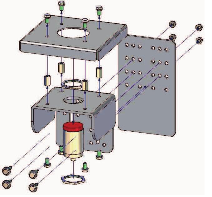
53 Exploded view Roller shaft bending Sensor

54 Reference / Tire migration Sensor assembled

55 Roller shaft Sensor assembled

56 Inductive sensor With analog output BI7-Q08-LIU Rectangular, height 8 mm Active face on top Metall, zinc die casting 4-wire, VDC Analog output 0 10 V and 0 20 ma Cable connection Wiring diagram Type code BI7-Q08-LIU Ident no Measuring range [A B] 1 4mm Mounting condition flush Repeatability ð 1 % of measuring range A - B ð 0.5 %, after warm-up 0.5 h Reproducibility ð 30 µm ð 15 µm, after a warm-up time of 0.5 h Linearity deviation ð 5 % Temperature drift ð ± 0.06 % / K Ambient temperature C Operating voltage Residual ripple No-load current I 0 Rated insulation voltage Short-circuit protection Wire breakage / Reverse polarity protection Output function Voltage output Current output Load resistance voltage output Load resistance, current output Measuring sequence frequency 15 30VDC ð 10 % U ss ð 8 ma ð 0.5 kv yes yes/ complete 4-wire, analog output 0 10VDC 0 20mA ï 4.7 kò ð 0.4 kò 200 Hz Functional principle Inductive TURCK sensors with analog output accomplish simple control tasks. They provide a current, voltage or frequency signal proportional to the target's distance. The output signal is linear to the distance of the target over the entire sensing range. Measuring range Construction Dimensions Housing material Connection Cable quality rectangular, Q08 32 x 20 x 8 mm metal, GD-Zn cable 4 mm, LifY-11Y, PUR, 2m Cable cross section 4 x 0.25 mm 2 Vibration resistance 55 Hz (1 mm) Shock resistance 30 g (11 ms) Protection class IP67 MTTF 751 years acc. to SN (Ed. 99) 40 C Edition T05:56:59+02:00 1 / 3 Hans Turck GmbH & Co.KG ñ D Mülheim an der Ruhr ñ Witzlebenstraße 7 ñ Tel ñ Fax ñ more@turck.com ñ

57 Inductive sensor With analog output BI7-Q08-LIU Distance W Distance S Distance G 12 mm 1.5 x B 6 x Sn Width of the active face B 20 mm Edition T05:56:59+02:00 2 / 3 Hans Turck GmbH & Co.KG ñ D Mülheim an der Ruhr ñ Witzlebenstraße 7 ñ Tel ñ Fax ñ more@turck.com ñ

58 Inductive sensor With analog output BI7-Q08-LIU Accessories Type code Ident no. Description Design IM43-13-SR Trip amplifier; 1-channel; input 0/4 20 ma or 0/2 10 V; supply of 2- or 3-wire transmitters/sensors; limit value adjustment via teach button; three relay outputs with one NO contact each; removable terminal blocks; 27 mm wide; universal voltage supply VUC; further Limit value indicators are described in our "Interface Technology" catalog. Edition T05:56:59+02:00 3 / 3 Hans Turck GmbH & Co.KG ñ D Mülheim an der Ruhr ñ Witzlebenstraße 7 ñ Tel ñ Fax ñ more@turck.com ñ
59 Fixation Bolts Sensor Holder Sensor Holder 30 Support Roller A Spacer Block 40 M3 A Turck Sensor BI7-Q08-LIU ~ 2mm Sensor Distance DRAWN T T T O O L S M M NAME ABC DATE 07/05/15 TomTom-Tools GmbH Zelgli Arni / Switzerland UNLESS OTHERWISE SPECIFIED DIMENSIONS ARE IN MILLIMETERS DIMENSIONS ± 0.1 mm ANGLES ± 0.1 TYPICAL EDGE CHAMFER 0.3x45 TITLE SIZE Sensor Holder For KHD Support Rollers DWG NO A4 FILE NAME: Sensor Holder KHD.dft SCALE: WEIGHT: SHEET 1 OF 1 REV
TomTom-Tools GmbH Wiesenstrasse Baden Switzerland. Phone 1: Phone 2: VAT ID:
 TomTom-Tools GmbH Wiesenstrasse 15 5400 Baden Switzerland www.tomtom-tools.com Phone 1: +41 79 774 06 42 Phone 2: +41 79 774 06 44 VAT ID: 698 468 Info@tomtom-tools.com User Manual: (Draft Version) OVALITY
Rotary Inclinometer III
 TomTom-Tools GmbH Zelgli 20 Phone: +41 79 774 06 44 8905 Arni Info@tomtom-tools.com Switzerland www.tomtom-tools.com User Manual: Rotary Inclinometer III 1. INTRODUCTION: The Rotary Inclinometer is a measurement
Magnetic Field Sensor for pneumatic cylinders BIM-UNT-AP6X-0.3-RS4
 For T-groove cylinders without mounting accessories Optional accessories for mounting on other cylindrical housings. One-hand mounting possible Fine adjustment tool and stopper directly mountable on the
Rotary Inclinometer. User Manual: (Draft Version)
") TomTom-Tools GmbH Phone 1: +41 79 774 06 42 Wiesenstrasse 15 Phone 2: +41 79 774 06 44 5400 Baden Info@tomtom-tools.com Switzerland www.tomtom-tools.com User Manual: (Draft Version) Rotary Inclinometer
TomTom-Tools GmbH Phone 1: +41 79 774 06 42 Wiesenstrasse 15 Phone 2: +41 79 774 06 44 5400 Baden Info@tomtom-tools.com Switzerland www.tomtom-tools.com User Manual: (Draft Version) Rotary Inclinometer
TomTom-Tools GmbH Zelgli 20 Phone: Arni
 TomTom-Tools GmbH Zelgli 20 Phone: +41 79 774 06 44 8905 Arni Info@tomtom-tools.com Switzerland www.tomtom-tools.com Measuring Wheel 1. INTRODUCTION: The Measuring Wheel is a measurement tool, which measures
Contactless Encoder with Stainless Steel Housing Incremental: ppr RI360P0-EQR24M0- INCRX2-H1181
 Compact, rugged housing Active face, plastic PA12-GF30 Housing, stainless steel V4A (1.4404) Status displayed via LED Immune to electromagnetic interference 1024 pulses per revolution (default) 360, 512,
MECHANICAL CONDITION MONITORING ON ROTARY KILNS. Measurement Tools for the Cement Industry
 MECHANICAL CONDITION MONITORING ON ROTARY KILNS Measurement Tools for the Cement Industry Agenda About TomTom-Tools GmbH New Kiln Axis Alignment System Tablet PC with Long Range Bluetooth Ovality Sensor
Magnetic Field Sensor for pneumatic cylinders BIM-UNT-AP6X-0.3-PSG3S/3GD
 ATEX category II 3 G, Ex zone 2 ATEX category II 3 D, Ex zone 22 For T-groove cylinders without mounting accessories Optional accessories for mounting on other cylindrical housings. One-hand mounting possible
Rotative measurement Incremental rotary encoder RI-10S10C-2B500-H1181
 Clamping flange, Ø 58 mm Solid shaft, Ø 10mm x 20mm Optical measuring principle Shaft material, stainless steel Protection class IP67 on the shaft side -40 +85 C Max. 6000 rev/min (continuous operation
Rotative measurement Absolute rotary encoder / Multiturn RM-29S10C-9A28B-R3M12
 Clamping flange, Ø 58 mm Solid shaft, Ø 10mm x 20mm Optical measuring principle Shaft material, stainless steel Protection class IP67 on the shaft side -40 +80 C max. 3000 rev/min PROFIBUS Removable bus
Rotative measurement Incremental rotary encoder Ri-10S10C-2B5000-H1181
 Clamping flange, Ø 58 mm Solid shaft, Ø 10mm x 20mm Optical measuring principle Shaft material, stainless steel Protection class IP67 on the shaft side -40 +85 C Max. 6000 rev/min (continuous operation
Rotative measurement Incremental rotary encoder Ri-10S10C-2B1000-H1181
 Clamping flange, Ø 58 mm Solid shaft, Ø 10 mm x 20 mm Optical measuring principle Shaft material, stainless steel Protection class IP67 on the shaft side -40 +85 C Max. 6000 rev/min (continuous operation
Magnetic Field Sensor for pneumatic cylinders BIM-UNT-AY1X/S1139
 ATEX category II 1 G, Ex Zone 0 ATEX category II 1 D, Ex Zone 20 For T-groove cylinders without mounting accessories Optional accessories for mounting on other cylindrical housings. One-hand mounting possible
magnetic sensors cylinder sensors 1200 cylinder sensors for 4mm round groove for festo or SMC cylinders
 cylinder sensors 1200 design 10 x 16 x 19.5mm Ø3.6 x 20.5mm Ø4.0 x 20.5mm C-groove cylinder sensor surface middle area temperature range up to +130 C wear-free and shock resistant because of fully electronic
INDUCTIVE SENSORS FOR UTILITY VEHICLES. Sense it! Connect it! Bus it! Solve it!
 INDUCTIVE SENSORS FOR UTILITY VEHICLES Sense it! Connect it! Bus it! Solve it! MOUNTING ACCESSORIES BSS-12 Dimensions/Types/Ident no./short description BSS-18 BSS- ø 12 34 2, 901321 Mounting accessories
fluid technology temperature sensors 1600 intelligent temperature sensor membrane keyboard, USB opto interface
 fluid technology temperature sensors 1600 1 dimensions Ø38 x 118mm temperature operating range -40 to +300 C temperature measuring range from -40 to +300 C M12 socket for PT100 resistance thermometer analog
UNIVERSAL MAGNETIC FIELD SENSORS FOR PNEUMATIC CYLINDERS. Sense it! Connect it! Bus it! Solve it!
 UNIVERSAL MAGNETIC FIELD SENSORS FOR PNEUMATIC CYLINDERS Sense it! Connect it! Bus it! Solve it! Universal magnetic field sensors for pneumatic cylinders The universal magnetic field sensors BIM-UNT and
UNIVERSAL MAGNETIC FIELD SENSORS FOR PNEUMATIC CYLINDERS. Sense it! Connect it! Bus it! Solve it!
 UNIVERSAL MAGNETIC FIELD SENSORS FOR PNEUMATIC CYLINDERS Sense it! Connect it! Bus it! Solve it! UNIVERSAL MAGNETIC FIELD SENSORS FOR PNEUMATIC CYLINDE The position detection of piston on all standard
TomTom-Tools GmbH Wiesenstrasse Baden Switzerland. Phone 1: Phone 2: VAT ID:
 TomTom-Tools GmbH Wiesenstrasse 15 5400 Baden Switzerland www.tomtom-tools.com Phone 1: +41 79 774 06 42 Phone 2: +41 79 774 06 44 VAT ID: 698 468 Info@tomtom-tools.com Product Description: ROTARY INCLINOMETER
Your Global Automation Partner. LTX Linear Position Sensors with SSI Interface. Operating instructions
 Your Global Automation Partner LTX Linear Position Sensors with SSI Interface Operating instructions Contents 2 Hans Turck GmbH & Co. KG T +49 208 4952-0 F +49 208 4952-264 more@turck.com www.turck.com
Barrel Size Metal Barrel Plastic Barrel. 5 Nm (3.7 ft-lb) 10 Nm (7.4 ft-lb) 15 Nm (11 ft-lb) 25 Nm (18 ft-lb) 90 Nm (66 ft-lb) 90 Nm (66 ft-lb)
 10 Nm (7.4 ft-lb) 15 Nm (11 ft-lb) 25 Nm (18 ft-lb) 90 Nm (66 ft-lb) 90 Nm (66 ft-lb)") Mounting TURCK inductive proximity sensors are manufactured with a shielded coil, designated by Bi in the part number, and a nonshielded coil, designated by Ni in the part number (See page C7). Embeddable
Mounting TURCK inductive proximity sensors are manufactured with a shielded coil, designated by Bi in the part number, and a nonshielded coil, designated by Ni in the part number (See page C7). Embeddable
JUMO MIDAS C18 SW. OEM pressure transmitter - seawater. Applications
 Delivery address: Mackenrodtstraße 4 Phone: +49 66 600-0 Fax: +49 66 600-607 Phone: +44 79 655 Fax: +44 79 656 Data Sheet 400 Page /6 JUMO MIDAS C8 SW OEM pressure transmitter - seawater Applications Water
CD34CNFLFxxx. Capacitive sensor, Foreground Suppression. Main features. Main functions. Description
 Capacitive sensor, Foreground Suppression Main features Compact housing Supply voltage: 10 to 30 VDC Output: 100 ma, NPN or PNP preset Make or break switching function LED indication for output and power
JUMO MIDAS S07 MA. OEM Pressure Transmitter - Maritime Approved. Applications. Brief description. Special features.
 Page /0 JUMO MIDAS S07 MA OEM Pressure Transmitter - Maritime Approved Applications In the shipping and offshore sector: HVAC (heating, ventilating, and air conditioning) Refrigeration engineering Compressors
RI360P0-QR24M0- INCRX2-H1181 Contactless Encoder Incremental
 RI360P0-QR24M0- INCRX2-H1181 Contactless Encoder Incremental Features Compact, rugged housing Many mounting possibilities Status displayed via LED Immune to electromagnetic interference 1024 pulses per
Electronic pressure switch with integrated analogue output
 Electronic pressure switch with integrated analogue output RE 30276/03.1 Replaces: 03.06 RE 30275 1/6 Type HEDE 10 /1/ Component series 2X tb0002 Table of contents Contents Page Features 1 Ordering code
INDUCTIVE SENSORS FOR ROTARY ACTUATORS. Sense it! Connect it! Bus it! Solve it!
 INDUCTIVE SENSORS FOR ROTARY ACTUATORS Sense it! Connect it! Bus it! Solve it! Inductive sensors for rotary actuators Versatility in a compact and robust design Position control on actuators and drives
Axial Turbine Flow Sensor Series Turbotron VTH 25 / VTI 25 / VTM 25
 Installation Instruction Axial Turbine Flow Sensor Series Turbotron VTH 25 / VTI 25 / VTM 25 Table of contents Page 1 Function of Turbotron 1 2 Safety instructions 2 3 Important notes and requirements
Temposonics. G-Series Analog Redundant. Magnetostrictive Position Sensors. Redundancy for enhanced safety
 Temposonics Magnetostrictive Position Sensors m SENSORS G-Series Redundant Temposonics GT2 and GT3 Measuring length 25-1500 mm Redundancy for enhanced safety Up to 3 totally separated, independent measuring
JUMO DELOS SI. Precision pressure transmitter with switching contacts and display. Application. Brief description. Key features.
 Data sheet 405052 Page 1/10 JUMO DELOS SI Precision pressure transmitter with switching contacts and display Application Food & pharma CIP/SIP systems Machine and system construction Air conditioning and
JUMO MIDAS S05 Pressure transmitter Type
 Data Sheet 40.00 Page /8 JUMO MIDAS S05 Pressure transmitter Type 4000 Brief description The JUMO MIDAS S05 pressure transmitter is available with both relative pressure and absolute pressure measurement
Electronic pressure switch with two switching outputs
 Electronic pressure switch with two switching outputs RE 30278/04.14 Replaces: 03.06 RE 30275 1/6 Type HEDE 10 /2/ Component series 2X tb0002 Table of contents Contents Page Features 1 Ordering code 2
Dusty / Dusty Ex. Low-Cost Broken Bag Detection. Operating Instructions. SWR engineering Messtechnik GmbH
 EN Dusty / Dusty Ex Operating Instructions Low-Cost Broken Bag Detection SWR engineering Messtechnik GmbH CONTENTS Page 1. Introduction.............................................................. 3 1.1
JUMO MIDAS S06. OEM-Pressure Transmitter Low Pressure. Applications. Brief description. Customer benefits. Special features
 Delivery address: Mackenrodtstraße 609 Fulda, Germany Postal address: 605 Fulda, Germany Phone: +9 66 600-0 Fax: +9 66 600-607 Harlow, Essex CM 0 DY, UK Phone: + 79 6 55 Fax: + 79 6 50 9 67 Myers Road
ACTUATORS POSITION SENSOR
 POSITION SENSOR 1 2 SUMMARY P INTRODUCTION PAGE 4 P LTS POSITION SENSOR PAGE 5 P LTL POSITION SENSOR PAGE 9 SUMMARY P LTE POSITION SENSOR PAGE 12 3 INTRODUCTION INTRODUCTION Magnetic position sensors are
SMART STOP TM WELKER SMART STOP DOES ALL STOPPING & SENSING FUNCTIONS IN ONE PART. MINIMIZES ENGINEERING, FIELD SET UP AND OPERATOR ADJUSTMENT TIME.
 ISO 9001 REGISTERED SMART STOP TM TM WELKER SMART STOP DOES ALL STOPPING & SENSING FUNCTIONS IN ONE PART. MINIMIZES ENGINEERING, FIELD SET UP AND OPERATOR ADJUSTMENT TIME. ELIMINATES: n NEED FOR SEPARATE
JUMO MIDAS S05. OEM Pressure Transmitter Universal. Applications. Brief description. Customer benefits. Special features
 Delivery address: Mackenrodtstraße 609 Fulda, Germany Postal address: 605 Fulda, Germany Phone: +9 66 600-0 Fax: +9 66 600-607 Harlow, Essex CM 0 DY, UK Phone: + 79 6 55 Fax: + 79 6 50 9 67 Myers Road
Operating instructions Safety sensor BNS About this document. Content. 6 Disassembly and disposal 6.1 Disassembly Disposal...
 Safety sensor BNS Disassembly and disposal. Disassembly..... Disposal... EU Declaration of conformity Operating instructions.............pages to Original x.000 / 0.0 / v.a. - 09009- / J / 0-0-0 / AE-Nr.
DB4 GUIDED SLIDE APPLICATIONS: ISO 9001 REGISTERED RETRACTABLE PINS & LOCATORS PUSHERS CROWDERS THRUSTERS SMALL LIFTERS SLIDES
 ISO 9001 REGISTERED DB4 GUIDED SLIDE 1/4" NPT or G1/4 PORTS RAP OR RIGID COUPLER TOOL MOUNTING SURFACE WELKER 70mm BORE PNEUMATIC CYLINDER SOLID STATE CYLINDER SWITCH NAAMS STOPS OR WELKER SMART STOPS
Pneumatic cylinders, piston-ø mm Double acting with magnetic piston DIN ISO 15552
 Pneumatic cylinders, piston-ø 32 100 mm Double acting with magnetic piston DIN ISO 15552 Technical data for series SL 050 450 Order code SL-032-0250-050 Series Piston-Ø Stroke length (mm) Type of cylinder
Thermal flow sensor TFS-35
 průmyslová elektronika Thermal flow sensor TFS-35 For sensing limit flow rates of fluid media and for monitoring their temperature. These sensors are intended for installation in pipes, in which the actual
manual magnetic linear measurement system MW10
 manual 1 Devices for operating voltage 24V DC for scanning a magnetic strip without reference point Table of contents 1 Warranty information... page 1 2 Identification... page 1 3 Mechanical mounting...
Differential Pressure and Flow meters Accessories for the Media Series
 Differential Pressure and Flow meters Accessories for the Media Series 7 8 9 10 11 6 12 Media 5 Media 6 Media 05 1 5 2 4 Media 4 3 Selection and application These accessories upgrade the devices of the
Compressed air counter DN
 Data sheet -6447 Compressed air counter DN 65-250, Measurement of norm volume flow in the measuring range 6.7 to 27500 m³/h (DN65 to DN350 or 2½ -10 ) Exchangeable fitting: Probe removal under pressure
Series 430 Type 3430 Pneumatic Indicating Controller for Temperature with Capillary Sensor Type 3432 Controller Station Type 3436 Transmitter Module
 Series 430 Type 3430 Pneumatic Indicating Controller for Temperature with Capillary Sensor Type 3432 Controller Station Type 3436 Transmitter Module Application Temperature controller for process engineering
8000 Series Liquid Flow Meters
 PRODUCT DATA SHEET 8000 Series Liquid Flow Meters Advanced microprocessorbased flow measurement technology in a compact, leak-tight package Flow ranges from 0.2 to 227 LPM / 0.05 to 60 GPM Accuracy of
Thermal flow sensor TFS-35
 průmyslová elektronika Thermal flow sensor TFS-35 For flow monitoring rates of liquids media and for monitoring of their temperature These sensors are intended for installation in pipes, in which the actual
Electric Mini Slides MSC-EL
 Electric Mini Slides MSC-EL R10EN 2604 (11.08) The Drive & Control Company Electric Mini Slides, MSC-EL R10EN 2604 (11.08) Mini Slides, MSC-EL Product Description 4 Selection Guide 6 Maximum thrust 6
Motor-drive mechanism, type BUL. Technical guide
 Motor-drive mechanism, type BUL Technical guide This Technical Guide has been produced to allow transformer manufacturers, and their designers and engineers, access to all the technical information required
Pneumatic cylinders, piston-ø 8 25 mm Single acting DIN ISO 6432
 Pneumatic cylinders, piston-ø 25 mm Single acting DIN ISO 6432 Technical data for series HE Order code HE-16-025 Series Piston-Ø Stroke length (mm) Design and function Single acting pneumatic cylinder
optical sensors through-beam, retro-reflective, dif. reflection sensors 2300 visible red light robust metal housing
 through-beam, retro-reflective, dif. reflection sensors 2300 1 design 15.4 x 50 x 50mm through-beam sensors operating distance 3m retro-reflective sensors operating distance 4 or 7m dif. reflection sensors
MGX. 2-jaw parallel self-centering pneumatic gripper series MGX. Parallel grippers. Pinze parallele MGX
 Pinze parallele MGX Parallel grippers MGX 2-jaw parallel self-centering pneumatic gripper series MGX Flat profile. Robust guide. High gripping force. Small weight and dimensions. High dimensional accuracy.
8000 Series Liquid Flow Meter
 PRODUCT DATA SHEET 8000 Series Liquid Flow Meter Advanced microprocessorbased flow measurement technology in a compact, leak-tight package. Flow ranges from 0.02 to 60 GPM / 0.1 to 227 LPM Accuracy of
Temposonics. Magnetostrictive Linear Position Sensors. GB-Series Analog Operation Manual
 Temposonics Magnetostrictive Linear Position Sensors GB-Series Analog Table of contents 1. Introduction...3 1.1 Purpose and use of this manual...3 1.2 Used symbols and warnings...3 2. Safety instructions...3
Installation and Operational Instructions for EAS - HTL housed overload clutch Sizes 01 3 Type 490._24.0
 Please read these Operational Instructions carefully and follow them accordingly! Ignoring these Instructions may lead to malfunctions or to clutch failure, resulting in damage to other parts. Contents:
Proximity sensors SMT/SME-10, for C-slot
 Proximity sensors SMT/SME-10, for C-slot Proximity sensors SMT/SME Product range overview Design Type of mounting Measuring principle Type Operating voltage range For C-slot Standard Insertable in slot
Powerful, durable and quick to mount. Magnetic and cylinder sensors from ifm electronic.
 Powerful, durable and quick to mount. Magnetic and cylinder sensors from ifm electronic. Magnetic sensors, cylinder sensors www.ifm.com/gb/cylindersensors fluid sensors and diagnostic systems position
INTELLIGENT TEMPERATURE SENSORS
 INTELLIGENT TEMPERATURE SENSORS TURCK THE FIRST ADDRESS FOR INDUSTRIAL AUTOMATION TURCK is one of the leading global company groups in the fi eld of industrial automation. The company has consistently
Wedge clamps
 Wedge clamps Wedge clamps for dies with tapered clamping edge Without position monitoring up to 160 C* 2.24000 With position monitoring lateral fastening up to 100 C** 2.24001 With position monitoring
Assembly and operating Instructions Bypass Flow Meter DST
 Assembly and operating Instructions Bypass Flow Meter 2 Contents 1. Foreword... 3 2. Safety... 3 2.1. Symbol and meaning... 3 2.2. General safety directions and exemption from liability... 3 2.3. Intended
CVR-625. Compact Vibrating Rod Instruction Manual
 CVR-625 Compact Vibrating Rod Instruction Manual BinMaster: Division of Garner Industries 7201 N. 98th St., Lincoln, NE 68507 402-434-9102 email: info@binmaster.com www.binmaster.com OPERATING INSTRUCTIONS
Electronic pressure switch. Type HEDE 10. Contents. Features. RE Edition: Replaces:
 Electronic pressure switch Type HEDE 10 RE 30277 Edition: 2017-02 Replaces: 2016-06 Component series 3X Maximum operating pressure 600 bar Features Suitable for measuring pressures in hydraulic systems
Control block VOFA with safety function
 Key features Innovative Versatile Reliable Easy to assemble Can be used for safe reversing of a hazardous movement (5/2-way solenoid valve) Can be used for safe venting (3/2-way solenoid valve function,
Cylindrical Sensors CY-100 SERIES panasonic-electric-works.net/sunx. Cylindrical Inductive Proximity Sensor GX-M SERIES.
 Cylindrical Sensors Photoelectric Sensor CY-100 SERIES Inductive Proximity Sensor GX-M SERIES Listing (2 m cable length type only) Cylindrical Inductive Proximity Sensor GX-M SERIES Cylindrical Photoelectric
CS1 COMPACT POWERED SLIDE
 ISO 9001 REGISTERED CS1 COMPACT POWERED SLIDE WELKER 50mm BORE COMPACT CYLINDER NPT OR G PORTS OPTIONAL SOLID STATE CYLINDER SWITCH AVAILABLE METAL SHROUD KEEPS RAILS COVERED AT ALL TIMES (MOVES WITH )
Model Pressure range ON/OFF output Linear output
 Digital Sensor Sensor with Easy-to-Read LED Display status can be checked at a glance from the red digital pressure value and analog bar displays. Measurement pressure is averaged by the chattering prevention
CATALOGUE Opto-Electronics STRACK LIFT AUTOMATION ILGT
 CATALOGUE Opto-Electronics 2018.1 ILGT 5.4 Opto-Electronics 2018.1 ILGT ILGT ILGT Opto-Electronics 2018.1 5.4 Safety light grid for power operated gates, also secure directly the wing path of vertically
Temposonics. M-Series Analog. Magnetostrictive Position Sensors. Temposonics MH Measuring length mm SENSORS
 Temposonics Magnetostrictive Position Sensors m SENSORS M-Series Temposonics MH Measuring length 50-2500 mm Compact Sensor for Mobile Hydraulics Linear, Absolute Measurement in Hydraulic Cylinders Contactless
DCT 533. Industrial Pressure Transmitter with IO-Link Interface. Stainless Steel Sensor
 DCT 5 Industrial Pressure Transmitter with IO-Link Interface Stainless Steel Sensor accuracy according to IEC 60770: standart: ± 0.5 % FSO sption: ± 0.5 % FSO Nominal pressure from 0... 00 mbar up to 0...
Digital Pressure Regulator Sentronic PLUS Series 614
 Digital Pressure Regulator Sentronic PLUS Series 14 Installation manual IM149-/R01 CONTENTS 1. Description... 1.1 Catalogue number... 1. Operating elements...4 1. Operating modes...4. Electrical connection...5.
PMS - PKS / PMW - PKW series
 features / series warranty warranty Innovative housing (double enclosure) Cutting oils resistant (for machines tool) Immersion proof (sealing IP 67/68) High frequency switching Complementary output (NO+NC),
Temposonics. M-Series Analog Redundant. Absolute, Non-Contact Positions Sensors. Temposonics MT Measuring length mm
 Temposonics Absolute, Non-Contact Positions Sensors M-Series Document Part Number 551218 Revision D Temposonics MT Measuring length 50-1500 mm Redundant Sensor for Mobile Hydraulics Redundant Sensor System
MAGNETO-INDUCTIVE POSITION DETECTORS
 MAGNETO-INDUCTIVE POSITION DETECTORS Series 88 Type 2 wires APPLICATION This four-wire proximity sensor will monitor stroke end and intermediate positions of pneumatic cylinders equipped with built-in
ACME SCREW LINEAR ACTUATOR. OVERALL DIMENSIONS La =Lc + Stroke Lc T Capacitor
 ACME SCREW LINEAR ACTUATOR ATL 10 AC motor Stroke OVERALL DIMENSIONS La =Lc + Stroke Lc T Capacitor Rear bracket SP Pin Standard head with threaded hollow bore 80 BA depth 17 Stroke end reed switches FCM
Temperature switch. Switching output 2 transistors PNP Logger Ring buffer: 3518 data points Sampling time: s, Off (0)
") Temperature switch Swiss based Trafag is a leading international supplier of high quality sensors and monitoring instruments for measurement of pressure and temperature. Applications Machine tools Hydraulic
Temperature switch Swiss based Trafag is a leading international supplier of high quality sensors and monitoring instruments for measurement of pressure and temperature. Applications Machine tools Hydraulic
LFT RADAR MICROONDE GUIDATE CONTROLLI DI LIVELLO. LFT level sensor the all-round talent with TDR technology. Dimensional drawing.
 LFT RADAR MICROONDE GUIDATE CONTROLLI DI LIVELLO LFT level sensor the all-round talent with TDR technology Latest technology: TDR sensor with coaxial probe for continual level measurements with analog
Electromagnetic Flow Monitor magphant
 Technical Information TI 036D/06/en No. 50078457 Electromagnetic Flow Monitor magphant Monitoring and measurement Flow monitoring with selectable limit values (relay output) Flow measurement via 4...20
FLEX PIVOT NWP WELKER SMART STOPS* OR NAAMS STOPS. 100mm BORE NON-LOCKING PNEUMATIC CYLINDER* NPT OR G PORTS*
 ISO 9001 REGISTERED FLEX PIVOT NWP FIXED SIDE MOUNTING WELKER SMART STOPS* OR NAAMS STOPS MOVABLE FLAT MOUNTING STYLE* MOVABLE BLADE MOUNTING STYLE* FIXED SIDE MOUNTING 100mm BORE NON-LOCKING PNEUMATIC
JUMO dtrans p35. Pressure Sensor with IO-Link. Application. Brief description. Customer benefits. Special features
 sales@jumo.co.uk info.us@jumo.net Page 1/10 JUMO dtrns p5 Pressure Sensor with IO-Link pplication Process automation Machines for the food and beverage industry General mechanical and apparatus engineering
Steering column and sensor
 Steering column and sensor Type LAB Series 1 x Nominal voltage 12 to 48 volt Output signal digital, analog and direction (option) HE 11874 / 09.2017 2 LAB HE 11874 / 09.2017 Page Content 4 4 5 6 7 7 8
Air Flow Controller M1compact Type-Summary FKM 130
 Air Flow Controller M1compact -Summary FKM 130 One-part sensor for controlling air and gaseous flows with integrated evaluation electronic. The air flow controller is mounted into the flow to be controlled
Inductive Proximity Sensor
 Inductive Proximity Sensor Square Proximity Sensor Terminal housing Active face changeable to one of every five Easy to install and same mounting dimensions as a standard style electromechanical limit
Universal Magnetic Field Sensors
 Universal Magnetic Field Sensors www.turck.com The BIM-UNT, a universal magnetic field sensor, is the latest addition to the inductive-magnetic family of switches by TURCK. It has the ability to detect
1.7. Portable insulation fault location system EDS3060/EDS3360 in combination with EDS460/461 systems
 Portable insulation fault location system EDS3060/EDS3360 in combination with EDS460/461 systems An additional function allows measuring residual currents in earthed power supplies (TN/TT systems) too.
Flow meters. Flow meters. Flow meters - Continuous and precise measurement of flow rates
 - Continuous and precise measurement of flow rates In order to guarantee smooth operation and consistent quality, many processes require constant in and outflow of liquid or gaseous media. Flow sensors
AirLINE and AirLINE Quick electrical/pneumatic Automation System
 AirLINE and AirLINE Quick electrical/pneumatic Automation System Type 8644 can be combined with Fully compatible with Rockwell Combination of Fieldbus, pilot valves and I/O modules higher fl exibility
Modular electrical and pneumatic automation system
 Modular electrical and pneumatic automation system Decentralised automatisation without control cabinet in protection type IP65 / IP67 Modular structure, also as central station with several decentralised
Ring Style Sensors 98 Altech Corp. 35 Royal Road Flemington, NJ Phone (908) Fax (908)
 Fax (908)") Ring Style Sensors RING STYLE INDUCTiVE PROXIMITY SENSORS Altech Ring Sensors are used for variety of applications including punching and stamping operations to detect small metal parts and for the identification
Ring Style Sensors RING STYLE INDUCTiVE PROXIMITY SENSORS Altech Ring Sensors are used for variety of applications including punching and stamping operations to detect small metal parts and for the identification
LINEAR ACTUATORS INDEX
 LINEAR ACTUATORS INDEX Linear actuators LMR Series LMR 01 thrust force up to 1 300 N DC motor... page 2 LMR 03 thrust force up to 6 000 N DC motor... page 3 Linear actuators ATL Series ATL 02 thrust force
Inductive Proximity Sensor
 ASH & ALAIN INDIA PVT LTD S-100, F.I.E.E., Okhla Industrial Area, Phase-ii, New Delhi-110020(India) Tel : 011-43797575 Fax : 011-43797574 E-mail : sales@ashalain.com Inductive Proximity Sensor E2Q3 Square
Series 7000 Torque Sensor for PTO-shafts
 Properties PTO (Power Take-Off) shaft with integrated torque and angle measurement Non-contact measurement system, high robustness Special for PTO shafts 1 ¾ und 1 3/8 Plug & Play solution, no additional
3RG4 BERO Inductive Proximity Switches
 3RG40 11 3RG40 11 0AA00 10/14 3RG40 11 0AB00 10/14 3RG40 11 0AF00 10/13 3RG40 11 0AF05 10/18 3RG40 11 0AF33 10/17 3RG40 11 0AG00 10/13 3RG40 11 0AG05 10/18 3RG40 11 0AG33 10/17 3RG40 11 0CC00 10/14 3RG40
8710 EN. Potentiometric Displacement Sensors. Models 8710, 8711
 Potentiometric Displacement Sensors Models 8710, 8711 Code: Delivery: Warranty: 8710 EN ex stock 24 months Model 8711 Model 8710 Application Displacement sensors models 8710 and 8711 with resistance tracks
Remote Process Actuation Control System AirLINE - Rockwell 1734 Point I/O System
 Remote Process Actuation Control System AirLINE - Rockwell 1734 Type 8644 can be combined with... Fully compatible with Rockwell 1734 Point I/O System Combination of Fieldbus, pilot valves and I/O modules
INLINE Flow sensor for hazardous area II 1 G/D - II 2 D - II 3 GD - I M1
 INLINE Flow sensor for hazardous area II G/D - II D - II GD - I M Type SE0 Ex can be combined with... Flow meter with NAMUR or NPN/PNP output signal Mounting, dismounting of electronics by a Quarter-Turn
Heating chamber with mechanical convection
 FED series 720 Drying ovens / Heating ovens Heating chamber with mechanical convection The multi-talented BINDER heating chamber of the FED series provides almost unlimited capacity and is particularly
CPLab / CP Factory. Application module magazine. Data sheets
 CPLab / CP Factory Application module magazine Data sheets Data sheet: Push-in fitting QSM-M5-4 #153304 Size Mini Nominal size 2.2 mm Type of seal on screw-in stud Sealing ring Container size 10 Design
Technical description... 1 Limit switch versions MR 6 Power tables... 6 Dimensions... 7 Spare part lists... 8
 Index Technical description... 1 Limit switch versions... 3 MR 6 Power tables... 6 Dimensions... 7 Spare part lists... 8 MS 12 Power tables... 10 Dimensions... 11 Spare part lists... 13 MR 30 Power tables...
INSERTION flowmeter with paddle wheel, ELEMENT design
 INSERTION flowmeter with paddle wheel, design Up to PN, size of measurement pipes: DN to DN400 Configurable outputs: one or two transistor output(s) and single or dual 4... ma analog output(s) Removable
SM-08. Features. Miniature Turbine Flowmeter for Fluid Media. Description: Application:
 SM-8 Miniature Turbine Flowmeter for Fluid Media Description: Features / High accuracy of measurement and resolution / Low deviation in mass-production / Plastic, brass or st. steel designs / Pressure-proof