SERIES RTC RODLESS CYLINDERS PNEUMATIC SHUTTLE TYPE
|
|
|
- Dulcie Lawson
- 5 years ago
- Views:
Transcription


1 SERIES RTC RODLESS CYLINDERS PNEUMATIC SHUTTLE TYPE

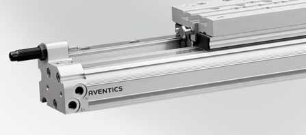
2 Series RTC Rodless Cylinder Pneumatic automation building block Series RTC (Rodless Thrust Cylinder)-High performance shuttle type rodless cylinders The Series RTC is the latest generation of rodless cylinders from AVENTICS, building on years of experience with rodless cylinder design. The economical RTC features a robust, virtually leak-free design with high speed capability. Offering inch and metric options in four versions, RTC's can be custom configured online. The guided versions are Easy-2-Combine capable when used with a connection kit to combine with other standard actuators to build modular automation systems. Shuttle and piston body in one piece: Robust design integrated for high strength and long life Sensor magnet standard Easy maintenance Sturdy, compact profile: Strong, yet light-weight aluminum Smaller profile than RexMover Ideal Cushioning: Adjustable pneumatic end-cushioning Impact bumpers reduce noise and absorb residual impact energy Sealing bands: Stainless steel reinforced polyurethane inner sealing band, unique shape makes cylinder more air tight than other brands Magnetically coupled outer band protects against dust, etc. Virtually leak-free design Sensor grooves (2) visible from 3 sides: ST4 sensors mechanically protected Internal groove provides cable channel Choice of air connections: On the side at both ends Or one end cover allows dual porting without pressure drop NPT or ISO-G (BSPP) ports Series RTC-BV Basic Version shown - Four main versions available: RTC-BV Basic Version RTC-CG Compact Guide RTC-HD Heavy Duty RTC-CKP Twin Guides (Guided versions are Easy-2-Combine capable with connection kit) High speed: Speeds up to 21 feet per second Many versions of RTC cylinders are available on our Quick Ship Focused delivery program, visit: Oval-shaped piston: Low height saves space Greater resistance to side load T-grooves for mounting: Easy installation of cylinders using two styles of foot mounts, or choose end cover mounts How to Order: Our online configurator allows you to design custom cylinders while preventing the selection of impossible configurations. Provides part number and CAD drawing immediately. Go to: and select "Configurators"
.")
3 Series RTC Rodless Cylinders AVENTICS 3 RTC-BV Basic Version Used at low and medium torques. Available in bore sizes 5/8 to 3 (16mm to 80mm). RTC-CG Compact Guide Used where high precision is required. Available in bore sizes 5/8 to 1-1/2 (16mm to 40mm). Uses Bosch Rexroth Linear miniature ball rail systems for all bores sizes except the largest, which uses the standard ball rail system. RTC-HD Heavy Duty Used with high loads and torques (Heavy Duty) where extra high precision is required. Available in bore sizes 5/8 to 2-1/2 (16 to 63mm). Uses Bosch Rexroth Linear standard ball rail system with steel guide. RTC - CKP Twin Guides Uses same steel guide rail as heavy-duty version, but has two guides. Available in bore sizes 16 to 32mm with metric ports and threads. Note: Guided versions are Easy-2-Combine capable when used with connection kit. Also available from Internet Configurator: RTC-RR Replacement Series RMC Basic Version RTC-SB Replacement Series RMC Slide Bearing Version (metric only) These are used only to replace a Series RMC (RexMover) cylinder. Not to be used for new design. Similar to RTC-BV but supplied with mounting hardware to provide the same hole mounting pattern and shuttle height as the RMC. Available in bore sizes 5/8 to 3 and 16 to 80mm. RTC-RI Replacement Series 170 Used only to replace a Series 170 cylinder. Not to be used for new design. Similar to RTC-BV but supplied with mounting hardware to provide the same hole mounting pattern and shuttle height as Series 170. Available in bore sizes 5/8 to 3 and 16 to 80mm. Series RTC Model Code:
4 4 AVENTICS Series RTC Rodless Cylinders Rodless cylinders Index Series RTC Inch version Rodless cylinder, RTC-BV Ø mm Compressed air connections UNF - 3/8 NPTF double-acting with magnetic piston integrated guide Basic Version cushioning: pneumatically, adjustable 7 Rodless cylinder, Series RTC-CG Ø mm Compressed air connections UNF - 1/4 NPTF double-acting with magnetic piston ball rail guide Compact Guide cushioning: pneumatically, adjustable Easy 2 Combine-capable with connection kit Rodless cylinder, Series RTC-HD Ø mm Compressed air connections UNF - 3/8 NPTF double-acting with magnetic piston ball rail guide Heavy Duty cushioning: pneumatically, adjustable Easy 2 Combine-capable with connection kit Metric version Rodless cylinder, Series RTC-BV Ø mm Ports: M7 - G 3/8 double-acting with magnetic piston integrated guide Basic Version cushioning: pneumatically, adjustable 24 Rodless cylinder, Series RTC-CG Ø mm Ports: M7 - G 1/4 double-acting with magnetic piston ball rail guide Compact Guide cushioning: pneumatically, adjustable Easy 2 Combinecapable with connection kit Rodless cylinder, Series RTC-HD Ø mm Ports: M7 - G 3/8 double-acting with magnetic piston ball rail guide Heavy Duty cushioning: pneumatically, adjustable Easy 2 Combinecapable with connection kit Rodless cylinder, Series CKP Ø mm Ports: M7 - G 1/8 double-acting with magnetic piston ball rail guide cushioning: pneumatically, adjustable Easy 2 Combine-capable with connection kit 41 Accessories Intermediate stop kit Kit for intermediate-stop adjustment for RTC-CG, RTC-HD 44 Cylinder mountings End cover mounting, MF1 for Series RTC-BV, RTC-CG, RTC-HD 47


5 Series RTC Rodless Cylinders AVENTICS 5 Rodless cylinders Index Series RTC Foot mounting, M41, M48 for Series RTC-BV, RTC-CG, RTC-HD 47 Compensating coupling, S44 for Series RTC-BV 48 Mounts and adustable stop for RTC-SB (formerly 277-3) End cover mounting M40 Ajustable stop Foot mounting M41 49 Clamping fi xtures for Series CKP-16, MSC-20, CKP-25, CKP-32, MSC Easy 2 Combine connection kits Easy 2 Combine, Connection kit For combination: CKP / CKP 53 Easy 2 Combine, Connection kit For combination: CKP / CKP 54 Centering rings 55 End stop Slide attachment for RTC-BV 56 Bracket for RTC-BV 57

6 6 AVENTICS Series RTC Rodless Cylinders Rodless cylinders Index Series RTC Sensors and sensor mountings, accessories ST4, Sensor mounting for Series ST4 to mount on cylinder CKP 58 Sensor, Series ST4 4 mm groove with cable open cable ends, 3-pin 4 mm groove with cable Plug, M8, 3-pin 4 mm groove with cable Plug, M8, 3-pin, with knurled screw 4 mm groove with cable Plug, M12, 3-pin, with knurled screw 58 Sensor, Series ST6 6 mm groove with cable open cable ends, 3-pin 6 mm groove with cable Plug, M8, 3-pin, with knurled screw 6 mm groove with cable Plug, M8, 3-pin 6 mm groove with cable Plug, M12, 3-pin, with knurled screw 64 Connecting cable, Series CN2 Socket, Snap-in plug Ø8, 3-pin, with detent without wire end ferrule, tin-plated 68 Connecting cable, Series CN2 Socket, M8, 3-pin open cable ends, 3-pin 69 T-groove nut for CKP, GPC, RTC 70 Cable holder to mount on cylinder RTC-SB (formerly 277-3) 70 Sensor mounting for ST6, to mount on cylinder RTC-SB (formerly 277-3) 70 Industrial shock absorber Kit for shock absorber adjustment for RTC and CKP 71 Industrial shock absorbers Series SA2-RT, for RTC-BV, -CG and HD Series SA1-MC, for RTC-SB (formerly 277-3) 72
7 Series RTC Rodless Cylinders AVENTICS 7 Rodless cylinders Inch Version Rodless cylinder, RTC-BV Ø mm Compressed air connections UNF - 3/8 NPTF double-acting with magnetic piston integrated guide Basic Version cushioning: pneumatically, adjustable Working pressure min./max. Ambient temperature min./max. Medium Oil content of compressed air Pressure for determining piston forces 29 psi / 116 psi +14 F / +140 F Compressed air 0 mg/m³ - 1 mg/m³ PSI Materials: Cylinder tube Covers Seals Sealing strips Ball rail table Aluminum, anodized Aluminum, anodized Polyurethane Polyurethane; Stainless steel Aluminum, anodized a24 Technical Remarks The pressure dew point must be at least 27 F under ambient and medium temperature and may not exceed 37 F. The delivered product is lubricated for lifetime. These pneumatic components with NPT or inch thread dimensions are only available from our US sales organization Piston Ø [mm] Piston force [lbf] Cushioning length [inch] Cushioning energy [in.lbs.] Speed max. [ft./s] Weight 0 mm stroke [lbs] mm stroke [lbs] Stroke max. [inch] Piston Ø [mm] Piston force [lbf] Cushioning length [inch] Cushioning energy [in.lbs.] Speed max. [ft./s] Weight 0 mm stroke [lbs] mm stroke [lbs] Stroke max. [inch]
8 8 AVENTICS Series RTC Rodless Cylinders Rodless cylinders Inch Version Rodless cylinder, RTC-BV Ø mm Compressed air connections UNF - 3/8 NPTF double-acting with magnetic piston integrated guide Basic Version cushioning: pneumatically, adjustable Permissible forces Fx, Fy, Fz and torques Mx, My, Mz With simultaneously moments on the cylinder this equation must be used in addition to the maximum moments check. In the cushioning phase of the movement additional forces occur and must be considered. Please use our calculation tool for rodless cylinders at Static Ø [mm] Ø [inch] Fx [N] Fy [N] Fz [N] Mx [Nm] My [Nm] Mz [Nm] 16 5/ / / / Dynamic Ø [mm] Ø [inch] Mx [Nm] My [Nm] Mz [Nm] 16 5/ / / / Max. play and recommended max. lever arm length L = lever arm

9 Series RTC Rodless Cylinders AVENTICS 9 Rodless cylinders Inch Version Rodless cylinder, RTC-BV Ø mm Compressed air connections UNF - 3/8 NPTF double-acting with magnetic piston integrated guide Basic Version cushioning: pneumatically, adjustable Ø [mm] Ø [inch] 16 5/ / / / α β Limit diagram for pneumatic cushioning for horizontal or vertical mounting v = Piston velocity [m/s] m = Cushionable mass [kg] The values for the cushionable mass m and piston velocity v must be on or below the graph for the selected piston diameter Support span Max. support span L [mm] as a function of F [N] at a deflection of 0.5 mm
10 10 AVENTICS Series RTC Rodless Cylinders Rodless cylinders Inch Version Rodless cylinder, RTC-BV Ø mm Compressed air connections UNF - 3/8 NPTF double-acting with magnetic piston integrated guide Basic Version cushioning: pneumatically, adjustable Dimensions in inches PL BU PM CU EE My RT PO SG FH E PP 1.10 TG MCF + S B ZD + S RX FS XX FR W7 W6 W1 W2 W3 GR My W4 Wd2 ZZ RU W5 Wd1 WH MCR S = stroke _inch Dimensions in inches Ø [mm] Ø [inch] B BU CU E EE FH FR FS GR PL PM 16 5/ *10-32 UNF/M /8 NPTF / /8 NPTF / /4 NPTF /4 NPTF / /8 NPTF /8 NPTF Ø [mm] Ø [inch] PO PP RT 1) RU 2) RX SG TG W1 W2 W3 W4 W5 W6 16 5/8 13, M4 M UNF *Can be selected in the configurator (M7 for high-speed applications), UNF is standard
11 Series RTC Rodless Cylinders AVENTICS 11 Rodless cylinders Inch Version Rodless cylinder, RTC-BV Ø mm Compressed air connections UNF - 3/8 NPTF double-acting with magnetic piston integrated guide Basic Version cushioning: pneumatically, adjustable Ø [mm] Ø [inch] PO PP RT 1) RU 2) RX SG TG W1 W2 W3 W4 W5 W , M5 M UNF /4 24, M6 M6 1/4-20 UNC /2 31, M6 M6 1/4-20 UNC ,5 1.4 M8 M6 1/4-20 UNC /2 45, M8 M8 1/4-20 UNC , M8 M8 1/4-20 UNC Ø [mm] Ø [inch] W7 Wd1 Wd2 ZZ WH ZD M [lbs] 3) 16 5/ M6 M M6 M / M8 M / M8 M M12 M / M12 M M12 M ) Thread depth: 0.35 inch for piston Ø 5/8-1 1/2, 0.47 inch for piston Ø 5/8-3 2) Thread depth: 0.24 inch for piston Ø 5/8-1, 0.40 inch for piston Ø 1 1/4-2, 0.59 inch for piston Ø 2 1/2-3 3) M = moving mass
12 12 AVENTICS Series RTC Rodless Cylinders Rodless cylinders Inch Version Rodless cylinder, Series RTC-CG Ø mm Compressed air connections UNF - 1/4 NPTF double-acting with magnetic piston ball rail guide Compact Guide cushioning: pneumatically, adjustable Easy 2 Combine-capable with connection kit Working pressure min./max. Ambient temperature min./max. Medium Oil content of compressed air Pressure for determining piston forces 29 psi / 116 psi +14 F / +140 F Compressed air 0 mg/m³ - 1 mg/m³ PSI a24 Materials: Cylinder tube Covers Seals Sealing strips Ball rail table Guide rail Aluminum, anodized Aluminum, anodized Polyurethane Polyurethane; Stainless steel Aluminum, anodized Steel, hardened An example configuration is illustrated. The delivered product may thus deviate from the illustration. Technical Remarks The pressure dew point must be at least 27 F under ambient and medium temperature and may not exceed 37 F. The delivered product is lubricated for lifetime. Use hydraulic shock absorbers for precise end position adjustment. These pneumatic components with NPT or inch thread dimensions are only available from our US sales organization Piston Ø [mm] Piston force [lbf] Cushioning length [inch] Cushioning energy [in.lbs.] Speed max. [ft./s] Weight 0 mm stroke [lbs] mm stroke [lbs] Stroke max. [inch]
13 Series RTC Rodless Cylinders AVENTICS 13 Rodless cylinders Inch Version Rodless cylinder, Series RTC-CG Ø mm Compressed air connections UNF - 1/4 NPTF double-acting with magnetic piston ball rail guide Compact Guide cushioning: pneumatically, adjustable Easy 2 Combine-capable with connection kit Permissible forces Fx, Fy, Fz and torques Mx, My, Mz With simultaneously moments on the cylinder this equation must be used in addition to the maximum moments check. In the cushioning phase of the movement additional forces occur and must be considered. Please use our calculation tool for rodless cylinders at Static Ø [mm] Ø [inch] Fx [N] Fy [N] Fz [N] Mx [Nm] My [Nm] Mz [Nm] 16 5/ / / Dynamic Ø [mm] Ø [inch] Mx [Nm] My [Nm] Mz [Nm] 16 5/ / / Recommended values for an expected lifetime of 3200 km Max. play and recommended max. lever arm length L = lever arm Ø [mm] Ø [inch] α β Lx Ly Lz 16 5/8 <0,1 <0, <0,1 <0, /4 <0,1 <0, /2 <0,1 <0,

14 14 AVENTICS Series RTC Rodless Cylinders Rodless cylinders Inch Version Rodless cylinder, Series RTC-CG Ø mm Compressed air connections UNF - 1/4 NPTF double-acting with magnetic piston ball rail guide Compact Guide cushioning: pneumatically, adjustable Easy 2 Combine-capable with connection kit Limit diagram for pneumatic cushioning for horizontal or vertical mounting v = Piston velocity [m/s] m = Cushionable mass [kg] The values for the cushionable mass m and piston velocity v must be on or below the graph for the selected piston diameter Support span Max. support span L [mm] as a function of F [N] at a deflection of 0.5 mm
15 Series RTC Rodless Cylinders AVENTICS 15 Rodless cylinders Inch Version Rodless cylinder, Series RTC-CG Ø mm Compressed air connections UNF - 1/4 NPTF double-acting with magnetic piston ball rail guide Compact Guide cushioning: pneumatically, adjustable Easy 2 Combine-capable with connection kit Dimensions in inches C ** My A-A** * * T GS Mz T1 SG PK FH EE 1) EE 1) RW RV T2 TF T TG RT V1 J B V2 PL BU V3 PM U2 RU U3 PL U1 SU PP EE PO CC MC ZD + S A-A SL HC HD GE GF RH RG RP W1 W2 HB HA GA GB GB W4 W3 Wd1 RG W5 W6 Wd2 GD W7 S = stroke T = Type of t-groove nut 1) Auxiliary air feeding An example configuration is illustrated. The delivered product may thus deviate from the illustration. ** RTC-CG 16 & 25: 2x Lube ports on each runner block RTC-CG 32 & 40: Lube nipple of funnel type with thread connection M
16 16 AVENTICS Series RTC Rodless Cylinders Rodless cylinders Inch Version Rodless cylinder, Series RTC-CG Ø mm Compressed air connections UNF - 1/4 NPTF double-acting with magnetic piston ball rail guide Compact Guide cushioning: pneumatically, adjustable Easy 2 Combine-capable with connection kit Dimensions in inches Ø [mm] Ø [inch] B C BU CC EE FH GA GB GD GE GF GS 16 5/ *10-32/M /8 NPTF / /8 NPTF / /8 NPTF Ø [mm] Ø [inch] HA HB HC HD J MC PK PL PM PN PO PP RG 1) 16 5/ M M / M / M6 Ø [mm] Ø [inch] RH 2) RP RT 3) RU 4) SG SL SU T W1 W2 W3 16 5/8 4xUNC 1/4-20 Ø 9 M5 M N xUNC 1/4-20 Ø 9 M5 M N /4 4xUNC 1/4-20 Ø 12 M6 M N /2 4xUNC 1/4-20 Ø 12 M6 M N Ø [mm] Ø [inch] W4 W5 W6 W7 Wd1 Wd2 T1 T2 TF TG U1 U2 U3 16 5/ M6 M , M6 M / M8 M / M8 M Ø [mm] Ø [inch] ZD M [lb] 5) 16 5/ / / ) Thread depth: 0.47 inch for piston Ø 5/8, 1 and 1 1/ inch for piston Ø 1 1/4 2) Thread depth: 0.50 inch for piston Ø 5/8-1 1/2 3) Thread depth: 0.35 inch for piston Ø 5/8-1 1/2 4) Thread depth: 0.40 inch for piston Ø 5/8-1 1/2 5) M = moving mass * Can be selected in the configurator (M7 for high-speed applications)
17 Series RTC Rodless Cylinders AVENTICS 17 Rodless cylinders Inch Version Rodless cylinder, Series RTC-HD Ø mm Compressed air connections UNF - 3/8 NPTF double-acting with magnetic piston ball rail guide Heavy Duty cushioning: pneumatically, adjustable Easy 2 Combine-capable with connection kit Working pressure min./max. Ambient temperature min./max. Medium Oil content of compressed air Pressure for determining piston forces 58 psi / 116 psi +14 F / +140 F Compressed air 0 mg/m³ - 1 mg/m³ PSI Materials: Cylinder tube Covers Seals Sealing strips Ball rail table Guide rail Aluminum, anodized Aluminum, anodized Polyurethane Polyurethane; Stainless steel Aluminum, anodized Steel, hardened An example configuration is illustrated. The delivered product may thus deviate from the illustration. a24 Technical Remarks The pressure dew point must be at least 27 F under ambient and medium temperature and may not exceed 37 F. The delivered product is lubricated for lifetime. Use hydraulic shock absorbers for precise end position adjustment. These pneumatic components with NPT or inch thread dimensions are only available from our US sales organization Piston Ø [mm] Piston force [lbf] Cushioning length [inch] Cushioning energy [in.lbs.] Speed max. [ft./s] Weight 0 mm stroke [lbs] mm stroke [lbs] Stroke max. [inch] Piston Ø [mm] 63 Piston force [lbf] Cushioning length [inch] Cushioning energy [in.lbs.] Speed max. [ft./s] 6.56 Weight 0 mm stroke [lbs] mm stroke [lbs] Stroke max. [inch]
18 18 AVENTICS Series RTC Rodless Cylinders Rodless cylinders Inch Version Rodless cylinder, Series RTC-HD Ø mm Compressed air connections UNF - 3/8 NPTF double-acting with magnetic piston ball rail guide Heavy Duty cushioning: pneumatically, adjustable Easy 2 Combine-capable with connection kit Permissible forces Fx, Fy, Fz and torques Mx, My, Mz With simultaneously moments on the cylinder this equation must be used in addition to the maximum moments check. In the cushioning phase of the movement additional forces occur and must be considered. Please use our calculation tool for rodless cylinders at Static Ø [mm] Ø [inch] Fx [N] Fy [N] Fz [N] Mx [Nm] My [Nm] Mz [Nm] 16 5/ / / / Dynamic Ø [mm] Ø [inch] Mx [Nm] My [Nm] Mz [Nm] 16 5/ / / / Recommended values for an expected lifetime of 3200 km

19 Series RTC Rodless Cylinders AVENTICS 19 Rodless cylinders Inch Version Rodless cylinder, Series RTC-HD Ø mm Compressed air connections UNF - 3/8 NPTF double-acting with magnetic piston ball rail guide Heavy Duty cushioning: pneumatically, adjustable Easy 2 Combine-capable with connection kit Max. play and recommended max. lever arm length L = lever arm Ø [mm] Ø [inch] α β Lx Ly Lz 16 5/8 <0,1 <0, <0,1 <0, /4 <0,1 <0, /2 <0,1 <0, <0,1 <0, /2 <0,1 <0, Limit diagram for pneumatic cushioning for horizontal or vertical mounting v = Piston velocity [m/s] m = Cushionable mass [kg] The values for the cushionable mass m and piston velocity v must be on or below the graph for the selected piston diameter
20 20 AVENTICS Series RTC Rodless Cylinders Rodless cylinders Inch Version Rodless cylinder, Series RTC-HD Ø mm Compressed air connections UNF - 3/8 NPTF double-acting with magnetic piston ball rail guide Heavy Duty cushioning: pneumatically, adjustable Easy 2 Combine-capable with connection kit Support span Max. support span L [mm] as a function of F [N] at a deflection of 0.5 mm
21 Series RTC Rodless Cylinders AVENTICS 21 Rodless cylinders Inch Version Rodless cylinder, Series RTC-HD Ø mm Compressed air connections UNF - 3/8 NPTF double-acting with magnetic piston ball rail guide Heavy Duty cushioning: pneumatically, adjustable Easy 2 Combine-capable with connection kit Dimensions in inches RW RV V3 C ** GA GS GB GB TT * K1 U1 FH T PO PO T1 SU SG V2 V1 PL BU PM U2 U3 RU PL * Mz EE PP CC MC T2 T RT GE ZD + S A-A GF SL J T3 TF B TG HC HD RG RG RP W4 GI GH HB HA W3 W2 W1 Wd1 RH GJ W5 W6 Wd2 GK W7 GD S = stroke T = Type of t-groove nut TT = Type of t-groove nut * Shock absorber optional in end cover for diameters
22 22 AVENTICS Series RTC Rodless Cylinders Rodless cylinders Inch Version Rodless cylinder, Series RTC-HD Ø mm Compressed air connections UNF - 3/8 NPTF double-acting with magnetic piston ball rail guide Heavy Duty cushioning: pneumatically, adjustable Easy 2 Combine-capable with connection kit Dimensions in inches A-A M y EE 1) EE 1) U2 U3 U4 RU GA GB GB GB PP PO U1 PK PN A-A 50/63 PN PM 1) Auxiliary air feeding An example configuration is illustrated. The delivered product may thus deviate from the illustration Dimensions in inches Ø [mm] Ø [inch] B C BU CC EE EF EG FH GA GB GD 16 5/ * UNF/M /8 NPTF / /8 NPTF / /4 NPTF /4 NPTF Ø 4,59 Ø 0, / /8 NPTF Ø 0,59 Ø 1, Ø [mm] Ø [inch] GE GF GH GI GJ GK GS HA HB HC HD J 16 5/ /20/ ,3 2,75 2, / ,25 3,3 1, / ,5 3 2, / ,5 4 2, ,6 3,9 2, / ,6 4 2, Ø [mm] Ø [inch] K1 MC PK PL PM PN PO PP PR PQ RG 1) RH 2) 16 5/ M5 4xUNC 1/ M5 4xUNC 1/ / M6 4xUNC 1/ / M6 4xUNC 1/ M8 4xUNC 5/16-18 *Can be selected in the configurator (M7 for high-speed applications), UNF is standard.
23 Series RTC Rodless Cylinders AVENTICS 23 Rodless cylinders Inch Version Rodless cylinder, Series RTC-HD Ø mm Compressed air connections UNF - 3/8 NPTF double-acting with magnetic piston ball rail guide Heavy Duty cushioning: pneumatically, adjustable Easy 2 Combine-capable with connection kit Ø [mm] Ø [mm] Ø [inch] K1 MC PK PL PM PN PO PP PR PQ RG 1) RH 2) / M8 4xUNC 5/16-18 Ø [inch] RP RQ RT 3) RU 4) SG SL SU T TT W1 W2 W3 W4 16 5/8 Ø 9 M5 M5 M M4 N Ø 9 M6 M5 M N6 N /4 Ø 12 M6 M6 M N6 N /2 Ø 12 M8 M6 M N6 N Ø 12 M8 M8 M N8 N /2 Ø 12 M8 M8 M N8 N Ø [mm] Ø [inch] W5 W6 W7 Wd1 Wd2 T1 T2 T3 TF TG U1 U2 U3 16 5/ M6 M , M6 M ,7 0, / M8 M , / M8 M , M12 M , / M12 M Ø [mm] Ø [inch] U4 ZD M [lb] 5) 16 5/ / / / ) Thread depth: 0.47 inch for piston Ø 5/8-1, 0.63 inch for piston Ø 5/8-1 1/2, 0.55 inch for piston Ø 5/8-3 2) Thread depth: 0.50 inch for piston Ø 5/8-3 3) Thread depth: 0.35 inch for piston Ø 5/8-1 1/2, 0.47 inch for piston Ø 5/8-3 4) Thread depth: 0.40 inch for piston Ø 5/8-3 5) M = moving mass

24 24 AVENTICS Series RTC Rodless Cylinders Rodless cylinders Metric Version Rodless cylinder, Series RTC-BV Ø mm Ports: M7 - G 3/8 double-acting with magnetic piston integrated guide Basic Version cushioning: pneumatically, adjustable Working pressure min./max. Ambient temperature min./max. Medium Oil content of compressed air Pressure for determining piston forces 29 psi / 116 psi +14 F / +140 F Compressed air 0 mg/m³ - 1 mg/m³ PSI Materials: Cylinder tube Covers Seals Sealing strips Ball rail table Aluminum, anodized Aluminum, anodized Polyurethane Polyurethane; Stainless steel Aluminum, anodized a24 Technical Remarks The pressure dew point must be at least 27 F under ambient and medium temperature and may not exceed 37 F. The delivered product is lubricated for lifetime. Piston Ø [mm] Piston force [lbf] Cushioning length [inch] Cushioning energy [in.lbs.] Speed max. [ft./s] Weight 0 mm stroke [lbs] mm stroke [lbs] Stroke max. [inch] Piston Ø [mm] Piston force [lbf] Cushioning length [inch] Cushioning energy [in.lbs.] Speed max. [ft./s] Weight 0 mm stroke [lbs] mm stroke [lbs] Stroke max. [inch]
25 Series RTC Rodless Cylinders AVENTICS 25 Rodless cylinders Metric Version Rodless cylinder, Series RTC-BV Ø mm Ports: M7 - G 3/8 double-acting with magnetic piston integrated guide Basic Version cushioning: pneumatically, adjustable Piston Ø Ports 16 M7 25 G 1/8 32 G 1/8 40 G 1/4 50 G 1/4 Stroke 3.94 R R R R R R R R R R R R R R R R R R R R R R R R R R R R R R R R R R R R R R Piston Ø Ports 63 G 3/8 80 G 3/8 Stroke R R R R R R R R R R R R R R Permissible forces Fx, Fy, Fz and torques Mx, My, Mz With simultaneously moments on the cylinder this equation must be used in addition to the maximum moments check. In the cushioning phase of the movement additional forces occur and must be considered. Please use our calculation tool for rodless cylinders on the Static Piston Ø Fx [N] Fy [N] Fz [N] Mx [Nm] My [Nm] Mz [Nm]
26 26 AVENTICS Series RTC Rodless Cylinders Rodless cylinders Metric Version Rodless cylinder, Series RTC-BV Ø mm Ports: M7 - G 3/8 double-acting with magnetic piston integrated guide Basic Version cushioning: pneumatically, adjustable Dynamic Piston Ø Mx [Nm] My [Nm] Mz [Nm] Max. play and recommended max. lever arm length L = lever arm Piston Ø α β Lx Ly Lz 16 0,5 2,0 ± ,5 2,0 ± ,6 1,5 ±0, ,4 1,0 ±0, ,4 1,0 ±0, ,3 1,0 ±0, ,3 1,0 ±0,

![pneumatic cushioning with vertical mounting 00138076 v = Piston velocity [m/s] m = Cushionable mass [kg] The values for the cushionable mass m and piston velocity](/docs-images/84/90682668/images/27-1.jpg "v must be on or below the graph for the selected piston diameter. 00138077 Support span Max. support span L [mm] as a function of F [N] at a deflection of 0.")
27 Series RTC Rodless Cylinders AVENTICS 27 Rodless cylinders Metric Version Rodless cylinder, Series RTC-BV Ø mm Ports: M7 - G 3/8 double-acting with magnetic piston integrated guide Basic Version cushioning: pneumatically, adjustable Limit diagram for pneumatic cushioning with horizontal mounting Limit diagram for pneumatic cushioning with vertical mounting v = Piston velocity [m/s] m = Cushionable mass [kg] The values for the cushionable mass m and piston velocity v must be on or below the graph for the selected piston diameter Support span Max. support span L [mm] as a function of F [N] at a deflection of 0.5 mm
28 28 AVENTICS Series RTC Rodless Cylinders Rodless cylinders Metric Version Rodless cylinder, Series RTC-BV Ø mm Ports: M7 - G 3/8 double-acting with magnetic piston integrated guide Basic Version cushioning: pneumatically, adjustable Piston Ø 16-80, Dimensions in mm PM CU EE My RT PO SG PP E FH 28 MC TG ZD + S B FS FR W7 W6 W3 W1 W2 GR Mz W4 Wd2 WH RU W5 Wd1 MC S = stroke Piston Ø B BU CU E EE FH FR FS GR MC PL PM PO M G 1/ G 1/ G 1/ G 1/ G 3/ G 3/ Piston Ø PP RT 1) RU 2) SG TG W1 W2 W3 W4 W5 W6 W7 Wd M5 M M M5 M M M6 M M M6 M M M8 M M M8 M M M8 M M12 Piston Ø Wd2 WH ZD M [kg] 3) 16 M M M M M M M ) thread depth: 9 mm for piston Ø mm, 12 mm for piston Ø mm 2) thread depth: 6 mm for piston Ø mm, 10 mm for piston Ø mm, 15 mm for piston Ø mm 3) M = moving mass
29 Series RTC Rodless Cylinders AVENTICS 29 Rodless cylinders Metric Version Rodless cylinder, Series RTC-CG Ø mm Ports: M7 - G 1/4 double-acting with magnetic piston ball rail guide Compact Guide cushioning: pneumatically, adjustable Easy 2 Combine-capable with connection kit Working pressure min./max. Ambient temperature min./max. Medium Oil content of compressed air Pressure for determining piston forces 29 psi / 116 psi +14 F / +140 F Compressed air 0 mg/m³ - 1 mg/m³ PSI a24 Materials: Cylinder tube Covers Seals Sealing strips Ball rail table Guide rail Aluminum, anodized Aluminum, anodized Polyurethane Polyurethane; Stainless steel Aluminum, anodized Steel, hardened An example configuration is illustrated. The delivered product may thus deviate from the illustration. Technical Remarks The pressure dew point must be at least 27 F under ambient and medium temperature and may not exceed 37 F. The delivered product is lubricated for lifetime. Use hydraulic shock absorbers for precise end position adjustment. Piston Ø [mm] Piston force [lbf] Cushioning length [inch] Cushioning energy [in.lbs.] Speed max. [ft./s] Weight 0 mm stroke [lbs] mm stroke [lbs] Stroke max. [inch] Piston Ø Ports 16 M7 25 G 1/8 32 G 1/8 40 G 1/4 Stroke 7.87 R R R R R R R R R R R R R R R R R R R R R R R R R R R R R R R
30 30 AVENTICS Series RTC Rodless Cylinders Rodless cylinders Rodless cylinders Rodless cylinder, Series RTC-CG Ø mm Ports: M7 - G 1/4 double-acting with magnetic piston ball rail guide Compact Guide cushioning: pneumatically, adjustable Easy 2 Combine-capable with connection kit Permissible forces Fx, Fy, Fz and torques Mx, My, Mz With simultaneously moments on the cylinder this equation must be used in addition to the maximum moments check. In the cushioning phase of the movement additional forces occur and must be considered. Please use our calculation tool for rodless cylinders at Static Piston Ø Fx [N] Fy [N] Fz [N] Mx [Nm] My [Nm] Mz [Nm] Dynamic Piston Ø Mx [Nm] My [Nm] Mz [Nm] Recommended values for an expected lifetime of 3200 km Max. play and recommended max. lever arm length L = lever arm

![532 Limit diagram for pneumatic cushioning with horizontal mounting Limit diagram for pneumatic cushioning with vertical mounting v = Piston velocity [m/s] m = Cushionable mass [kg] The values for](/docs-images/84/90682668/images/31-1.jpg "the cushionable mass m and piston velocity v must be on or below the graph for the selected piston diameter. 00138078 00138079 Support span Max.")
31 Series RTC Rodless Cylinders AVENTICS 31 Rodless cylinders Metric Version Rodless cylinder, Series RTC-CG Ø mm Ports: M7 - G 1/4 double-acting with magnetic piston ball rail guide Compact Guide cushioning: pneumatically, adjustable Easy 2 Combine-capable with connection kit Piston Ø α β Lx Ly Lz 16 <0,1 <0, <0,1 <0, <0,1 <0, <0,1 <0, Limit diagram for pneumatic cushioning with horizontal mounting Limit diagram for pneumatic cushioning with vertical mounting v = Piston velocity [m/s] m = Cushionable mass [kg] The values for the cushionable mass m and piston velocity v must be on or below the graph for the selected piston diameter Support span Max. support span L [mm] as a function of F [N] at a deflection of 0.5 mm
32 32 AVENTICS Series RTC Rodless Cylinders Rodless cylinders Metric Version Rodless cylinder, Series RTC-CG Ø mm Ports: M7 - G 1/4 double-acting with magnetic piston ball rail guide Compact Guide cushioning: pneumatically, adjustable Easy 2 Combine-capable with connection kit Ø mm, Dimensions in mm C ** My A-A** * * T GS Mz T1 SG PK FH EE 1) EE 1) RW RV T2 TF T TG RT V1 J B V2 PL BU V3 PM U2 RU U3 PL U1 SU PP EE PO CC MC ZD + S SL A-A HC HD GE GF RH RG RP W1 W2 HB HA GA GB GB W4 W3 Wd1 RG W5 W6 Wd2 GD W7 S = stroke T = Type of t-groove nut 1) Auxiliary air feeding An example configuration is illustrated. The delivered product may thus deviate from the illustration. * Shock absorber optional in end cover for diameters ** RTC-CG 16 & 25: 2x Lube ports on each runner block RTC-CG 32 & 40: Lube nipple of funnel type with thread connection M Piston Ø B C BU CC EE FH GA GB GD GE GF GS HA xM xG 1/
33 Series RTC Rodless Cylinders AVENTICS 33 Rodless cylinders Metric Version Rodless cylinder, Series RTC-CG Ø mm Ports: M7 - G 1/4 double-acting with magnetic piston ball rail guide Compact Guide cushioning: pneumatically, adjustable Easy 2 Combine-capable with connection kit Piston Ø B C BU CC EE FH GA GB GD GE GF GS HA xG 1/ xG 1/ Piston Ø HB HC HD J MC PK PL PM PN PO PP RG 1) RH 2) M5 UNC 1/ M5 UNC 1/ M6 UNC 1/ M6 UNC 1/4-20 Piston Ø RP RT 3) RU 4) RV RW SG SL SU T V1 V2 V3 W1 16 Ø 9 M5 M5 M5x8 Ø 9H8x1, N Ø 9 M5 M6 M5x8 Ø 9H8x1, N Ø 12 M6 M6 M6x10 Ø 12H8x2, N Ø 12 M6 M6 M6x10 Ø 12H8x2, N Piston Ø W2 W3 W4 W5 W6 W7 Wd1 Wd2 T1 T2 TF TG U M6 M M6 M M8 M M8 M Piston Ø U2 U3 ZD M [kg] 5) ) thread depth: 12 mm for piston Ø 16, 25 & 40 mm; 10,5 mm for piston Ø 32 2) thread depth: 12,7 mm for piston Ø mm 3) thread depth: 9 mm for piston Ø mm 4) thread depth: 10 mm for piston Ø mm 5) M = moving mass
34 34 AVENTICS Series RTC Rodless Cylinders Rodless cylinders Metric Version Rodless cylinder, Series RTC-HD Ø mm Ports: M7 - G 3/8 double-acting with magnetic piston ball rail guide Heavy Duty cushioning: pneumatically, adjustable Easy 2 Combine-capable with connection kit Working pressure min./max. Ambient temperature min./max. Medium Oil content of compressed air Pressure for determining piston forces 58 psi / 116 psi +14 F / +140 F Compressed air 0 mg/m³ - 1 mg/m³ PSI Materials: Cylinder tube Covers Seals Sealing strips Ball rail table Guide rail Aluminum, anodized Aluminum, anodized Polyurethane Polyurethane; Stainless steel Aluminum, anodized Steel, hardened An example configuration is illustrated. The delivered product may thus deviate from the illustration. a24 Technical Remarks The pressure dew point must be at least 27 F under ambient and medium temperature and may not exceed 37 F. The delivered product is lubricated for lifetime. Use hydraulic shock absorbers for precise end position adjustment. Piston Ø [mm] Piston force [lbf] Cushioning length [inch] Cushioning energy [in.lbs.] Speed max. [ft./s] Weight 0 mm stroke [lbs] mm stroke [lbs] Stroke max. [inch] Piston Ø [mm] 63 Piston force [lbf] Cushioning length [inch] Cushioning energy [in.lbs.] Speed max. [ft./s] 6.56 Weight 0 mm stroke [lbs] mm stroke [lbs] Stroke max. [inch]
35 Series RTC Rodless Cylinders AVENTICS 35 Rodless cylinders Metric Version Rodless cylinder, Series RTC-HD Ø mm Ports: M7 - G 3/8 double-acting with magnetic piston ball rail guide Heavy Duty cushioning: pneumatically, adjustable Easy 2 Combine-capable with connection kit Piston Ø Ports 16 M7 25 G 1/8 32 G 1/8 40 G 1/4 50 G 1/4 Stroke 7.87 R R R R R R R R R R R R R R R R R R R R R R R R R R R R R R R R R R R R R R Piston Ø Ports 63 G 3/8 Stroke R R R R R R R Permissible forces Fx, Fy, Fz and torques Mx, My, Mz With simultaneously moments on the cylinder this equation must be used in addition to the maximum moments check. In the cushioning phase of the movement additional forces occur and must be considered. Please use our calculation tool for rodless cylinders on the Static Piston Ø Fx [N] Fy [N] Fz [N] Mx [Nm] My [Nm] Mz [Nm]
36 36 AVENTICS Series RTC Rodless Cylinders Rodless cylinders Metric Version Rodless cylinder, Series RTC-HD Ø mm Ports: M7 - G 3/8 double-acting with magnetic piston ball rail guide Heavy Duty cushioning: pneumatically, adjustable Easy 2 Combine-capable with connection kit Dynamic Piston Ø Mx [Nm] My [Nm] Mz [Nm] Recommended values for an expected lifetime of 3200 km Max. play and recommended max. lever arm length L = lever arm Piston Ø α β Lx Ly Lz 16 <0,1 <0, <0,1 <0, <0,1 <0, <0,1 <0, <0,1 <0, <0,1 <0,

37 Series RTC Rodless Cylinders AVENTICS 37 Rodless cylinders Metric Version Rodless cylinder, Series RTC-HD Ø mm Ports: M7 - G 3/8 double-acting with magnetic piston ball rail guide Heavy Duty cushioning: pneumatically, adjustable Easy 2 Combine-capable with connection kit Limit diagram for pneumatic cushioning with horizontal mounting Limit diagram for pneumatic cushioning with vertical mounting v = Piston velocity [m/s] m = Cushionable mass [kg] The values for the cushionable mass m and piston velocity v must be on or below the graph for the selected piston diameter Support span Max. support span L [mm] as a function of F [N] at a deflection of 0.5 mm
38 38 AVENTICS Series RTC Rodless Cylinders Rodless cylinders Metric Version Rodless cylinder, Series RTC-HD Ø mm Ports: M7 - G 3/8 double-acting with magnetic piston ball rail guide Heavy Duty cushioning: pneumatically, adjustable Easy 2 Combine-capable with connection kit Ø mm, Dimensions in mm RW RV V3 C ** GA GS GB GB TT * K1 U1 FH T PO PO T1 SU SG V2 V1 PL BU PM U2 U3 RU PL * Mz EE PP CC MC T2 T RT GE ZD + S A-A GF SL J T3 TF B TG HC HD RG RG RP W4 GI GH HB HA W3 W2 W1 Wd1 RH GJ W5 W6 Wd2 GK W7 GD S = stroke T = Type of t-groove nut TT = Type of t-groove nut * Shock absorber optional in end cover for diameters ** RTC-HD 16 & 25: funnel type lube nipple with thread M3 RTC-HD 32-63: lube nipple DIN with thread M
39 Series RTC Rodless Cylinders AVENTICS 39 Rodless cylinders Metric Version Rodless cylinder, Series RTC-HD Ø mm Ports: M7 - G 3/8 double-acting with magnetic piston ball rail guide Heavy Duty cushioning: pneumatically, adjustable Easy 2 Combine-capable with connection kit A-A M y EE 1) EE 1) U2 U3 U4 RU GA GB GB GB PP PO U1 PK PN A-A 50/63 PN PM 1) Auxiliary air feeding An example configuration is illustrated. The delivered product may thus deviate from the illustration Piston Ø B C BU CC EE FH GA GB GD GE GF GH GI M /20/ G 1/ / G 1/ G 1/ G 1/ G 3/ Piston Ø GJ GK GS HA HB HC HD J K1 MC PK PL PM N/A N/A Piston Ø PN PO PP RG 1) RH 2) RP RT 3) RU 4) RV RW SG SL M5 UNC 1/4-20 Ø 9 M5 M5 M5x8 Ø 9H8x1, M5 UNC 1/4-20 Ø 9 M5 M6 M5x8 Ø 9H8x1, M6 UNC 1/4-20 Ø 12 M6 M6 M6x10 Ø 12H8x2, M6 UNC 1/4-20 Ø 12 M6 M6 M6x10 Ø 12H8x2, N/A M8 UNC 5/16-18 Ø 12 M8 M N/A 63 N/A M8 UNC 5/16-18 Ø 12 M8 M N/A Piston Ø SU T TT V1 V2 V3 W1 W2 W3 W4 W5 W6 W N4 N N6 N N6 N
40 40 AVENTICS Series RTC Rodless Cylinders Rodless cylinders Metric Version Rodless cylinder, Series RTC-HD Ø mm Ports: M7 - G 3/8 double-acting with magnetic piston ball rail guide Heavy Duty cushioning: pneumatically, adjustable Easy 2 Combine-capable with connection kit Piston Ø SU T TT V1 V2 V3 W1 W2 W3 W4 W5 W6 W N6 N N/A N8 N N/A N8 N Piston Ø Wd1 Wd2 T1 T2 T3 TF TG U1 U2 U3 U4 ZD M [kg] 5) 16 M6 M M6 M M8 M M8 M M12 M M12 M ) thread depth: 12 mm for piston Ø 16 25, 16 mm for piston Ø 32 40, 14 mm for piston Ø ) thread depth: 12,7 mm for piston Ø mm 3) thread depth: 9 mm for piston Ø mm, 12 mm for piston Ø mm 4) thread depth: 10 mm for piston Ø mm 5) M = moving mass
41 Series RTC Rodless Cylinders AVENTICS 41 Rodless cylinders Metric Version Rodless cylinder, Series CKP Ø mm Ports: M7 - G 1/8 double-acting with magnetic piston ball rail guide cushioning: pneumatically, adjustable Easy 2 Combine-capable with connection kit Working pressure min./max. Ambient temperature min./max. Medium temperature min./max. Medium Max. particle size Pressure for determining piston forces 3 bar / 8 bar -10 C / +60 C -10 C / +60 C Compressed air 5 μm 6,3 bar a24 Materials: Covers Seals Sealing strips Ball rail table Guide rail Aluminum, anodized Polyurethane Polyurethane; Stainless steel Aluminum, anodized Steel, hardened An example configuration is illustrated. The delivered product may thus deviate from the illustration. The pressure dew point must be at least 15 C under ambient and medium temperature and may not exceed 3 C. The delivered product is lubricated for lifetime. This product may only be operated with oil-free, dry compressed air. Technical Remarks The pressure dew point must be at least 15 C under ambient and medium temperature and may not exceed 3 C. The delivered product is lubricated for lifetime. This product may only be operated with oil-free, dry compressed air. Piston Ø [mm] Piston force [N] Cushioning length [mm] Cushioning energy [J] Speed max. [m/s] Stroke max. [mm] Piston Ø Ports 16 M7 25 G 1/8 32 G 1/8 Stroke 100 R R R R R R R R R R R R R R R R R R R R R R R R R R R R R R Weight [kg] Piston Ø Stroke
42 42 AVENTICS Series RTC Rodless Cylinders Rodless cylinders Metric Version Rodless cylinder, Series CKP Ø mm Ports: M7 - G 1/8 double-acting with magnetic piston ball rail guide cushioning: pneumatically, adjustable Easy 2 Combine-capable with connection kit Permissible forces Fx, Fy, Fz and torques Mx, My, Mz With simultaneously moments on the cylinder this equation must be used in addition to the maximum moments check. In the cushioning phase of the movement additional forces occur and must be considered. Please use our calculation tool for rodless cylinders at Max. dynamic forces and torques Piston Ø Fx [N] Fy [N] Fz [N] Mx [Nm] My [Nm] Mz [Nm] Recommended values for an expected lifetime of 3200 km Horizontally mounted, with pneumatic cushioning Vertically mounted, with pneumatic cushioning v = Piston velocity [m/s] m = Cushionable mass [kg]
43 Series RTC Rodless Cylinders AVENTICS 43 Rodless cylinders Metric Version Rodless cylinder, Series CKP Ø mm Ports: M7 - G 1/8 double-acting with magnetic piston ball rail guide cushioning: pneumatically, adjustable Easy 2 Combine-capable with connection kit Dimensions t = depth * CKP 16: 2x Lube ports on each runner block CKP 25 & 30: Lube nipple of funnel type with thread connection M Piston Ø B E BU CC EE FH GA GB GC GD GN GE GF M G 1/ G 1/ Piston Ø GH GI GJ GK GL GM GT GU MC PL PM PO PP Piston Ø PS PT PU PW Q1 Q2 Q3 RG Ø RP RQ Ø RR Ø RS RT M5 9 F7 M5 t=10,5 4 F7 9 F7 M M5 9 F7 M6 t=14,5 5 F7 12 F7 M M6 12 F7 M6 t=14,5 6 F7 12 F7 M6

44 44 AVENTICS Series RTC Rodless Cylinders Rodless cylinders Accessories Series RTC Accessories Kit for intermediate-stop adjustment for RTC-CG, RTC-HD Technical Remarks The pressure dew point must be at least 27 F under ambient and medium temperature and may not exceed 37 F. The oil content of compressed air must remain constant during the life cycle. Use only the approved oils from AVENTICS, see chapter Technical information. A parts kit always consists of several individual parts. Overview drawing 1) 2) 3) 4) 1) Shock absorber parts kit 2) Parts set for intermediate stop 3) Clamping plate parts kit 4) Parts kit for 15x120 profile 20462
45 Series RTC Rodless Cylinders AVENTICS 45 Rodless cylinders Accessories Series RTC Accessories Part No. Ø25 Ø32 Ø40 Weight kg R RTC-CG 1) 0.4 R RTC-CG 1) 0.35 R RTC-CG 1) 0.35 R RTC-HD 1) 0.3 R RTC-HD 1) 0.35 R RTC-HD 1) 0.35 R RTC-CG RTC-HD RTC-CG RTC-HD RTC-CG RTC-HD 2) 0.3 R R RTC-CG RTC-HD RTC-CG RTC-HD RTC-CG RTC-HD RTC-CG RTC-HD 1) Shock absorber parts kit 2) Parts set for intermediate stop 3) Clamping plate parts kit 4) Parts kit for 15x120 profile Order the shock absorber separately RTC-CG RTC-HD RTC-CG RTC-HD 3) 0.3 4) 0.3 Dimensions M5 A ,7 M14 max , max D min 112, ,
46 46 AVENTICS Series RTC Rodless Cylinders Rodless cylinders Accessories Series RTC Accessories - Kit for intermediate-stop adjustment (cont.) Intermediate stop on left L min 130 Intermediate stop on right R C 308 min 21,5 83, B , Part No. A B C D L (min) R (min) R R R R R R

![Piston Ø For series W3 W4 W6 W7 Wd2 Weight [lbs] R402002728 16, 25 RTC-BV RTC-CG RTC-HD R402002729 32, 40 RTC-BV RTC-CG RTC-HD R402002730 50 RTC-BV RTC-CG RTC-HD](/docs-images/84/90682668/images/47-2.jpg "R402002731 63, 80 RTC-BV RTC-CG RTC-HD Delivery quantity [Piece] 8 / 13 18 13,5 19,8 M6 0.4409 2 16 / 22 26 19 26,8 M8 0.6613 2 11 70 22 32,7 M12 0.")
47 Series RTC Rodless Cylinders AVENTICS 47 Rodless cylinders Accessories Series RTC Accessories End cover mounting, MF1 for Series RTC-BV, RTC-CG, RTC-HD W7 W6 W4 W ØWd Part No. Piston Ø For series W3 W4 W6 W7 Wd2 Weight [lbs] R , 25 RTC-BV RTC-CG RTC-HD R , 40 RTC-BV RTC-CG RTC-HD R RTC-BV RTC-CG RTC-HD R , 80 RTC-BV RTC-CG RTC-HD Delivery quantity [Piece] 8 / ,5 19,8 M / ,8 M ,7 M / ,7 M Material: Steel Foot mounting, M41, M48 for Series RTC-BV, RTC-CG, RTC-HD ) see data sheet for the respective product variant

48 48 AVENTICS Series RTC Rodless Cylinders Rodless cylinders Accessories Series RTC Accessories - Foot mounting, M41, M48 (cont.) Part No. Piston Ø For series Wd1 W5 W7 W8 Weight [lbs] R , 25 RTC-BV RTC-CG RTC-HD R , 40 RTC-BV RTC-CG RTC-HD R , 63, 80 RTC-BV RTC-CG RTC-HD R , 25 RTC-BV RTC-CG RTC-HD R , 40 RTC-BV RTC-CG RTC-HD R , 63, 80 RTC-BV RTC-CG RTC-HD Fig. 1 M41 Fig. 2 M48 Material: Aluminum Fig. Delivery quantity [Piece] 6, Fig , Fig Fig , Fig , Fig Fig. 2 4 Compensating coupling, S44 for Series RTC-BV

![30,5 35 150 90 45 ±24 120 80 60 15 5 Part No. Piston Ø H RU RV RX Weight [lbs] R402002403 16, 25 0,15 0,4 M6 6.6 11 0.2204 R402002404 32, 40 0,15 0,4 M8 9 15 0.](/docs-images/84/90682668/images/49-1.jpg "6613 R402002405 50, 63, 80 0,15 0,4 M10 11 15 1.76 Material: Aluminum End cover mounting, M40 for Series RTC-SB (formerly 277-3) D277_004 P277_007 S = stroke Delivered in pairs Part No.")
49 Series RTC Rodless Cylinders AVENTICS 49 Rodless cylinders Accessories Series RTC Accessories - Compensating coupling, S44 (cont.) Part No. Piston Ø For series DH DU FU FV FE FF GT GU GV R , 25 RTC-BV 17, ± R , 40 RTC-BV ,5 ± R , 63, 80 RTC-BV 30, ± Part No. Piston Ø H RU RV RX Weight [lbs] R , 25 0,15 0,4 M R , 40 0,15 0,4 M R , 63, 80 0,15 0,4 M Material: Aluminum End cover mounting, M40 for Series RTC-SB (formerly 277-3) D277_004 P277_007 S = stroke Delivered in pairs Part No. For series Ø Ø AB AR AU BH BR E SA TR RTC-SB 16 5, , , RTC-SB , RTC-SB ,
50 50 AVENTICS Series RTC Rodless Cylinders Rodless cylinders Accessories Series RTC Accessories Adjustable stop for RTC-SB P277_006 Part No. For series Ø E 1) L 2) S 3) Material Weight [lbs] RTC-SB 16 ±5 79 M12x1 Aluminum black anodized RTC-SB 25 ±5 79 M12x1 Aluminum 1.3 black anodized RTC-SB 32 ± M14x1,5 Aluminum black anodized ) recommended setting 2) extra length per stop 3) Shock absorber size (without shock absorber) for slide bearing guide version Foot mounting, M41 for Series RTC-SB 16 (formerly 277-3) P277_008 D277_006 S = stroke Part No. For series Ø B BH HH HU LL RN Ø RO SK SL TR RTC-SB ,3 58,2 6 5, ,5 18 Part No. For series TU RTC-SB 16 73
51 Series RTC Rodless Cylinders AVENTICS 51 Rodless cylinders Accessories Series RTC Accessories Foot mounting, M41 for Series RTC-SB (formerly 277-3) P277_008 D277_005 S = stroke Delivered in pairs Part No. For series Ø BD BH HH HU LL RN Ø RO RTC-SB SK SL Ø SS TR TU
52 52 AVENTICS Series RTC Rodless Cylinders Rodless cylinders Accessories Series CKP Accessories Clamping fixtures for mounting CKP for Series CKP-16, MSC-20, CKP-25, CKP-32, MSC Part No. For series 1) Typ A B C D E F G H R R R R R R R R R R R R R ) countersink for screw Material: Aluminum CKP-16 MSC-20 CKP-16 MSC-20 CKP-16 MSC-20 CKP-16 MSC-20 CKP-16 MSC-20 CKP-16 MSC-20 CKP-25 CKP-32 MSC-25 CKP-25 CKP-32 MSC-25 CKP-25 CKP-32 MSC-25 CKP-25 CKP-32 MSC-25 CKP-25 CKP-32 MSC-25 CKP-25 CKP-32 MSC-25 CKP-25 CKP-32 MSC-25 M M M M M M M M M M M M M
53 Series RTC Rodless Cylinders AVENTICS 53 Rodless cylinders Accessories Series CKP Accessories Easy 2 Combine, Connection kit For combination: CKP / CKP Materials: Centering sleeve Subbase Screws Stainless steel Aluminum Steel, galvanized connection kit consisting of: angle brackets, clamping fixtures, T-groove nuts, screws, centering rings Easy 2 Combine basic Easy 2 Combine add-on part Weight Part No. [kg] CKP-16, CKP-25 CKP R CKP-25 CKP R CKP-32 Y-axis connected by the profile (carriage travels) CKP R R Y-axis connected by the carriage (profile travels) ) basic 2) add-on-part m = mass Part No. X 1) Y 2) X/Y A R CKP-16 CKP-25 CKP X/Y B X/Y C D m [kg] Weight kg R CKP-25 CKP R CKP-32 CKP R CKP-32 CKP
54 54 AVENTICS Series RTC Rodless Cylinders Rodless cylinders Accessories Series CKP Accessories Easy 2 Combine, Connection kit For combination: CKP / CKP Materials: Centering rings Clamping fixtures Screws T-groove nut Stainless steel Aluminum Steel, galvanized Steel, galvanized Connection kit consisting of: Clamping fixtures, T-groove nut, screws, centering rings Easy 2 Combine basic Easy 2 Combine add-on part Weight Part No. [kg] CKP-16, CKP-25 CKP R CKP-25 CKP R CKP-32 CKP R CKP R Y-axis connected by the profile (carriage travels)
 Y 2) A Weight kg R039120045 CKP-16 CKP-25 CKP-16 96 106 R039120046 CKP-25 CKP-25 116 0.3 R039120047 CKP-32 CKP-25 135 0.3 R039120048 CKP-32 CKP-32 150 0.4 1) basic 2) add-on-part m = mass 0.")
55 Series RTC Rodless Cylinders AVENTICS 55 Rodless cylinders Accessories Series CKP Accessories Y-axis connected by the carriage (profile travels) Part No. X 1) Y 2) A Weight kg R CKP-16 CKP-25 CKP R CKP-25 CKP R CKP-32 CKP R CKP-32 CKP ) basic 2) add-on-part m = mass 0.2 Centering rings _a Part No. Ø A k6 B k6 C ±0,1 D 0,2 E +0,2 Material Delivery quantity [Piece] R ,4 3 Stainless steel 6 Fig. 1 R ,5 3 Stainless steel 6 Fig. 1 R ,6 4 Stainless steel 6 Fig. 1 R ,0 4 Stainless steel 6 Fig. 1 R Stainless steel 6 Fig. 1 R ,4 3 1,5 Stainless steel 6 Fig. 2 R ,4 3,5 1,5 Stainless steel 6 Fig. 2 R ,5 3,5 1,5 Stainless steel 6 Fig. 2 R ,6 4,0 2 Stainless steel 6 Fig. 2 R Stainless steel 6 Fig. 2 Fig.
56 56 AVENTICS Series RTC Rodless Cylinders Rodless cylinders Accessories Series RTC Accessories Slide attachment for RTC-BV end stop C D B E A E F G H I Q S R T A J A P K L M N O Part No. For series Ø A B ØC D E F G H I R RTC-BV M R RTC-BV M R RTC-BV M R RTC-BV M Part No. J K L M N O P Q R S R M6 R M6 R M6 R M8 Part No. T Material Weight [lbs] R Steel 1.1 galvanized R Steel 1.1 galvanized R Steel 1.1 galvanized R Steel galvanized 1.1

57 Series RTC Rodless Cylinders AVENTICS 57 Rodless cylinders Accessories Series RTC Accessories Bracket for RTC-BV end stop Ø25 / 50 Ø32-40 C C D D E E A A A B F G H I J N O A B F H G J N O I A K L M Q P A K L M Q P Part No. For series Ø ØA B C D E F G H I R RTC-BV M MF14x R RTC-BV M MF14x R RTC-BV M MF20x Part No. J ØK L M ØN ØO P Q Material Weight [lbs] R H Steel 1.1 galvanized R H Steel 1.1 galvanized R H Steel galvanized 1.1 Note: brackets are pre-threaded for shock absorbers (shown later in catalog)
58 BN BK BU RL + / / ~ 58 AVENTICS Series RTC Rodless Cylinders Rodless cylinders Accessories Series RTC Accessories ST4, Sensor mounting for Series ST4 to mount on cylinder CKP Part No. For series CKP Material Weight [kg] R ST4 16 Aluminum R ST4 25, 32 Aluminum Note that Series CKP are normally delivered with 2 pairs of sensor holders. Sensor, Series ST4 4 mm groove with cable open cable ends, 3-pin Certificates UL (Underwriters Laboratories) Ambient temperature min./max. -22 F / +176 F Protection class IP65, IP67 Switching point precision [mm] ±0,1 Switching logic NO (make contact) Display LED LED status display Yellow Vibration resistance Hz, 1 mm Shock resistance 30 g / 11 ms Mounting screw Combination: slotted and hexagon socket Materials: Housing Cable sheath Polyamide, fiber-glass reinforced Polyurethane Technical Remarks The max. switching capacity must not be exceeded. PNP BN BK BU RL Type of contact / + / ~ Reed + electronic PNP Cable length DC operating voltage min./max. Voltage drop U at Imax DC switching current, max. AC switching current, max. [ft.] [V] [V] [A] [A] Switching capacity Part No R / 30 I*Rs 0,13 0,13 3 W / 3 VA 16.4 R R / 30 2, R BN R BK RL electronic NPN 10 / 30 2, NPN BU 16.4 R interfaces: open cable ends; 3-pin short circuit resistant; Protected against polarity reversal
59 Series RTC Rodless Cylinders AVENTICS 59 Rodless cylinders Accessories Series RTC Accessories Dimensions A B 2,9 4,7 2) 1) C Ø2,2 BN BU BK 3 x 0,09 mm 2 30 L 1) LED 2) Switching point L = cable length BN = brown, BK = black, BU = blue Part No. A B C R R R R R R Sensor, Series ST4 4 mm groove with cable Plug, M8, 3-pin Certificates UL (Underwriters Laboratories) Ambient temperature min./max. -22 F / +176 F Protection class IP65, IP67 Switching point precision [mm] ±0,1 Switching logic NO (make contact) Display LED LED status display Yellow Vibration resistance Hz, 1 mm Shock resistance 30 g / 11 ms Mounting screw Combination: slotted and hexagon socket Materials: Housing Cable sheath Polyamide, fiber-glass reinforced Polyurethane Technical Remarks The max. switching capacity must not be exceeded.
60 BN BK BU RL + / / ~ 60 AVENTICS Series RTC Rodless Cylinders Rodless cylinders Accessories Series RTC Accessories - Sensor, Series ST4 (cont.) 4 mm groove with cable Plug, M8, 3-pin Type of contact Cable length DC operating voltage min./max. Voltage drop U at Imax DC switching current, max. AC switching current, max. [ft.] [V] [V] [A] [A] Switching capacity Part No. / + / ~ Reed / 30 I*Rs 0,13 0,13 3 W / 3 VA R BN + BK RL electronic PNP / 30 2, R PNP BU BN + BK RL electronic NPN / 30 2, R NPN BU interfaces: Plug; M8; 3-pin short circuit resistant; Protected against polarity reversal Dimensions B A 2,9 4,7 2) 1) C Ø2,2 Ø8 7, M8 36 L 1) LED 2) Switching point L = cable length Pin assignment: 1 = (+), 3 = (-), 4 = (OUT) Part No. A B C R R R
61 BN BK BU BN BK BU RL RL + / / ~ + / / ~ Series RTC Rodless Cylinders AVENTICS 61 Rodless cylinders Accessories Series RTC Accessories Sensor, Series ST4 4 mm groove with cable Plug, M8, 3-pin, with knurled screw Certificates UL (Underwriters Laboratories) Ambient temperature min./max. -22 F / +176 F Protection class IP65, IP67 Switching point precision [mm] ±0,1 Switching logic NO (make contact) Display LED LED status display Yellow Vibration resistance Hz, 1 mm Shock resistance 30 g / 11 ms Mounting screw Combination: slotted and hexagon socket Materials: Housing Cable sheath Polyamide, fiber-glass reinforced Polyurethane Technical Remarks The max. switching capacity must not be exceeded. Type of contact Cable length DC operating voltage min./max. Voltage drop U at Imax DC switching current, max. AC switching current, max. [ft.] [V] [V] [A] [A] Switching capacity Part No. / + / ~ Reed / 30 I*Rs 0,13 0,13 3 W / 3 VA R BN + BK RL electronic PNP / 30 2, R PNP BU / + / ~ Reed / 30 I*Rs 0,13 0,13 3 W / 3 VA R BN + BK RL electronic PNP / 30 2, R PNP BU interfaces: Plug; M8; 3-pin; with knurled screw short circuit resistant; Protected against polarity reversal
62 62 AVENTICS Series RTC Rodless Cylinders Rodless cylinders Accessories Series RTC Accessories - Sensor, Series ST4 (cont.) 4 mm groove with cable Plug, M8, 3-pin, with knurled screw Dimensions A B 2,9 M8 4,7 2) Ø2,2 1) C ~37 L 1) LED 2) Switching point L = cable length Pin assignment: 1 = (+), 3 = (-), 4 = (OUT) Part No. A B C R R R R Sensor, Series ST4 4 mm groove with cable Plug, M12, 3-pin, with knurled screw Certificates UL (Underwriters Laboratories) Ambient temperature min./max. -22 F / +176 F Protection class IP65, IP67 Switching point precision [mm] ±0,1 Switching logic NO (make contact) Display LED LED status display Yellow Vibration resistance Hz, 1 mm Shock resistance 30 g / 11 ms Mounting screw Combination: slotted and hexagon socket Materials: Housing Cable sheath Polyamide, fiber-glass reinforced Polyurethane Technical Remarks The max. switching capacity must not be exceeded.
63 BN BK BU RL + / / ~ Series RTC Rodless Cylinders AVENTICS 63 Rodless cylinders Accessories Series RTC Accessories Type of contact Cable length DC operating voltage min./max. Voltage drop U at Imax DC switching current, max. AC switching current, max. [ft.] [V] [V] [A] [A] Switching capacity Part No. / + / ~ Reed / 30 I*Rs 0,13 0,13 3 W / 3 VA R BN + BK RL electronic PNP / 30 2, R PNP BU interfaces: Plug; M12; 3-pin; with knurled screw short circuit resistant; Protected against polarity reversal Dimensions B A 2,9 4,7 2) 1) C Ø2,2 1 4 M12 3 ~47 L 1) LED 2) Switching point L = cable length Pin assignment: 1 = (+), 3 = (-), 4 = (OUT) Part No. A B C R R
64 BN BK BU RL + / / ~ 64 AVENTICS Series RTC Rodless Cylinders Rodless cylinders Accessories Series RTC Accessories Sensor, Series ST6 6 mm groove with cable open cable ends, 3-pin _2 Ambient temperature min./max. -13 F / +158 F Protection class IP69K Switching point precision [mm] ±0,1 Switching capacity 3 W / 3 VA Vibration resistance Hz, 1 mm Shock resistance 30 g / 11 ms Materials: Housing Cable sheath Polyamide Polyurethane BN BK PNP BU RL Type of contact / + / ~ Reed + electronic PNP Cable length DC operating voltage min./max. Operational voltage AC min./max. Voltage drop U at Imax DC switching current, max. AC switching current, max. [ft.] [V] [V] [V] [A] [A] Part No / / 30 I*Rs 0,13 0, R / 30-2, R Part No R Protective resistor for reed Max. switching frequency Operating current, not switched Operating current, switched [Ω] [khz] [ma] [ma] 15 < 0,3 - < 10 ma Yellow 1) R ) Protected against polarity reversal - < 1,0 < 20 ma < 30 ma Yellow 2) 2) short circuit resistant; Protected against polarity reversal interfaces: without wire end ferrule, tin-plated; 3-pin UL (Underwriters Laboratories) LED Note Dimensions 30,5 L 36 x 0,07 mm 2 4,2 1* 3* 2,8 3 x 0,14 mm 2 40 BN BU BK 6,2 X 2* 9,15 15,3 1* = switching point 2* = clamping screw 3* = LED L = cable length BN = brown, BK = black, BU = blue X = electronic: 6 mm, Reed: 10 mm _b
65 1 4 3 BN BK BU RL + / / ~ Series RTC Rodless Cylinders AVENTICS 65 Rodless cylinders Accessories Series RTC Accessories Sensor, Series ST6 6 mm groove with cable Plug, M8, 3-pin, with knurled screw _5 Certificates UL (Underwriters Laboratories) Ambient temperature min./max. -13 F / +158 F Protection class IP65, IP67 Switching point precision [mm] ±0,1 DC operating voltage min./max. 10 V - 30 V Switching capacity 3 W / 3 VA LED status display Yellow Vibration resistance Hz, 1 mm Shock resistance 30 g / 11 ms PNP BN BK BU RL Type of contact / + / ~ Reed + electronic PNP Cable length Materials: Housing Operational voltage AC min./max. Voltage drop U at Imax DC switching current, max. Polyamide AC switching current, max. Protective resistor for reed [ft.] [V] [V] [A] [A] [Ω] Part No / 30 I*Rs 0,13 0, , R BN + 4 BK RL electronic NPN , NPN 3 BU Part No. Max. switching frequency Operating current, not switched Operating current, switched [khz] [ma] [ma] < 0,3 - < 10 ma 1); 3) ); 4) < 1,0 < 20 ma < 30 ma 1); 4) R ); 4) < 1,0 < 20 ma < 30 ma 1); 4) 1) Material Cable sheath: Polyurethane 2) Material Cable sheath: Polyvinyl chloride 3) Protected against polarity reversal 4) short circuit resistant; Protected against polarity reversal interfaces: Plug; M8; 3-pin; with knurled screw Note Dimensions 30,5 L ,2 4,2 1* 3* Ø 2, M8 X 2* 9,25 13,7 1* = switching point 2* = clamping screw 3* = LED L = cable length X = electronic: 6 mm, Reed: 10 mm Pin assignment: 1 = (+), 3 = (-), 4 = (OUT) _d
66 1 4 3 BN BK BU RL + / / ~ 66 AVENTICS Series RTC Rodless Cylinders Rodless cylinders Accessories Series RTC Accessories Sensor, Series ST6 6 mm groove with cable Plug, M8, 3-pin _3 Certificates UL (Underwriters Laboratories) Ambient temperature min./max. -13 F / +158 F Protection class IP65, IP67 Switching point precision [mm] ±0,1 DC operating voltage min./max. 10 V - 30 V Switching capacity 3 W / 3 VA LED status display Yellow Vibration resistance Hz, 1 mm Shock resistance 30 g / 11 ms Materials: Housing Cable sheath Polyamide Polyurethane Type of contact Cable length Operational voltage AC min./max. Voltage drop U at Imax DC switching current, max. AC switching current, max. Protective resistor for reed [ft.] [V] [V] [A] [A] [Ω] Part No. / + / ~ Reed / 30 I*Rs 0,13 0, BN + 4 BK RL electronic PNP , PNP 3 BU 1 BN + 4 BK RL electronic NPN , NPN 3 BU Part No. Max. switching frequency Operating current, not switched Operating current, switched [khz] [ma] [ma] < 0,3 - < 10 ma 1) < 1,0 < 20 ma < 30 ma 2) < 1,0 < 20 ma < 30 ma 2) 1) Protected against polarity reversal 2) short circuit resistant; Protected against polarity reversal interfaces: Plug; M8; 3-pin Note Dimensions 30,5 L 7, ,2 4,2 1* 3* Ø 2, M8 X 2* 9,25 13,7 1* = switching point 2* = clamping screw 3* = LED L = cable length X = electronic: 6 mm, Reed: 10 mm Pin assignment: 1 = (+), 3 = (-), 4 = (OUT) _a
67 1 4 3 BN BK BU RL + / / ~ Series RTC Rodless Cylinders AVENTICS 67 Rodless cylinders Accessories Series RTC Accessories Sensor, Series ST6 6 mm groove with cable Plug, M12, 3-pin, with knurled screw _4 Certificates UL (Underwriters Laboratories) Ambient temperature min./max. -13 F / +158 F Protection class IP65, IP67 Switching point precision [mm] ±0,1 DC operating voltage min./max. 10 V - 30 V Switching capacity 3 W / 3 VA LED status display Yellow Vibration resistance Hz, 1 mm Shock resistance 30 g / 11 ms Materials: Housing Cable sheath Polyamide Polyurethane Type of contact Cable length Operational voltage AC min./max. Voltage drop U at Imax DC switching current, max. AC switching current, max. Protective resistor for reed [ft.] [V] [V] [A] [A] [Ω] Part No. / + / ~ Reed / 30 I*Rs 0,13 0, BN + 4 BK RL electronic PNP , PNP 3 BU Part No. Max. switching frequency Operating current, not switched Operating current, switched [khz] [ma] [ma] < 0,3 - < 10 ma 1) < 1,0 < 20 ma < 30 ma 2) 1) Protected against polarity reversal 2) short circuit resistant; Protected against polarity reversal interfaces: Plug; M12; 3-pin; with knurled screw Note Dimensions 30,5 L 1 4 6,2 4,2 1* 3* Ø 2,9 8 47,5 M12 3 X 2* 9,25 13,7 1* = switching point 2* = clamping screw 3* = LED L = cable length X = PNP: 6 mm, reed: 10 mm Pin assignment: 1 = (+), 3 = (-), 4 = (OUT) _c

68 68 AVENTICS Series RTC Rodless Cylinders Rodless cylinders Accessories Series RTC Accessories Connecting cable, Series CN2 Socket, Snap-in plug Ø8, 3-pin, with detent without wire end ferrule, tin-plated Protection class Wire cross-section IP65 0 in² Materials: Housing color Cable sheath Black Polyvinyl chloride P322_141_a Technical Remarks The specified protection class is only valid in assembled and tested state. Operational voltage Max. current Number of wires Cable exit Cable length L Weight Part No. [V DC] [V AC] [A] [ft.] [lbs] straight Dimensions 8 5,7 4,5 0,5 30 Ø3,5 L D523_104_a L = length!translate! Buchse_3-polig (1) BN=brown (3) BU=blue (4) BK=black

69 Series RTC Rodless Cylinders AVENTICS 69 Rodless cylinders Accessories Series RTC Accessories Connecting cable, Series CN2 Socket, M8, 3-pin open cable ends, 3-pin Protection class IP67 Materials: Housing color Cable sheath Cable color Black Polyvinyl chloride Black _b Technical Remarks The specified protection class is only valid in assembled and tested state. Operational voltage [V DC] [V AC] Max. current Number of wires Wire crosssection Cable exit Cable length L Weight [A] [in²] [ft.] [lbs] straight 180 Part No Dimensions M 8x1 3,5 9 *) 24 L 3,5 D523_104_b L = length *) With 15 m cable length Ø12!translate! Buchse_3-polig (1) BN=brown (3) BU=blue (4) BK=black
 Material Weight [lbs] 3842523142 N6 CKP, GPC, RTC M5 Steel 0.0066 galvanized 3842514931 N8 CKP, GPC, RTC M8 Steel galvanized 0.")
 2,45 M2,5 3 30 P277_012 00132552 Part No.")
70 70 AVENTICS Series RTC Rodless Cylinders Rodless cylinders Accessories Series RTC Accessories T-groove nut for CKP, GPC, RTC Mge0312b7 Part No. Type For series 2) Material Weight [lbs] N6 CKP, GPC, RTC M5 Steel galvanized N8 CKP, GPC, RTC M8 Steel galvanized ) Spring 2) Thread connection For N4 grooves on CKP 16 a square nut according to DIN 557 can be used. Cable holder to mount on cylinder RTC-SB (formerly 277-3) 2,45 M2, P277_ Part No. Material Aluminum Sensor mounting for Series ST6 to mount on cylinder RTC-SB (formerly 277-3) Part No. For series Ø Material R ST Aluminum
71 Series RTC Rodless Cylinders AVENTICS 71 Rodless cylinders Accessories Series RTC Accessories Kit for shock absorber adjustment for RTC and CKP Ambient temperature min./max. -- / Part No. Single parts Ø16 Ø25 Ø32 Ø40 Ø50 Ø63 R ) 2) RTC-HD RTC-CG CKP R ) 2) RTC-HD RTC-CG CKP RTC-HD RTC-CG CKP RTC-HD RTC-CG R ) RTC-HD RTC-HD R ) 2) RTC-HD RTC-CG CKP R ) 2) RTC-HD RTC-CG CKP RTC-HD RTC-CG CKP RTC-HD RTC-CG R ) RTC-HD RTC-HD
72 72 AVENTICS Series RTC Rodless Cylinders Rodless cylinders Accessories Series RTC Accessories - Kit for shock absorber adjustment for RTC and CKP (cont.) Part No. Single parts Ø16 Ø25 Ø32 Ø40 Ø50 Ø63 R ) RTC-HD RTC-CG R ) RTC-HD RTC-CG RTC-CG R ) RTC-HD R ) RTC-CG R ) RTC-HD R ) RTC-HD RTC-HD R ) RTC-HD RTC-CG CKP R ) RTC-HD RTC-CG CKP R ) RTC-HD RTC-CG CKP RTC-HD RTC-CG R ) RTC-HD RTC-HD Part No. Weight [kg] R R R R R R R R R R R R R R R R Industrial shock absorber, Series SA2-RT Self-compensating, for RTC-BV, -CG and HD Ambient temperature min./max. Medium +14 F / +140 F Oil Materials: Cylinder tube Piston rod Lock nut Steel, bronzed Stainless steel, hardened Steel, bronzed
73 Series RTC Rodless Cylinders AVENTICS 73 Rodless cylinders Accessories Series RTC Accessories - Industrial Shock Absorber, SA2-RT (cont.) Type Stroke for Effective mass me min./max. SA2-RT Return spring force min./max. impact speed min./max. [inch] [lbs] [lbf] [ft./s] Part No RTC / / / 16.4 R RTC / / / 14.1 R RTC / / / 7.87 R RTC-25,-32, / / / R RTC-25,-32, / / / 8.2 R RTC-25,-32, / / / 3.28 R RTC-50, / / / R RTC-50, / / / 8.53 R RTC-50, / / / 3.28 R Part No. Mounting Mounting thread Delivery unit R M12x1 R M12x1 R M12x1 R M14x1,5 R Lock nut M14x1,5 1 R M14x1,5 R M20x1,5 R M20x1,5 R M20x1,5 Dimensions E SW H A ØB L D K _a H = stroke A = mounting thread Part No. Type Mounting thread ØB D E H K L SW R SA2-RT M12x R SA2-RT M12x R SA2-RT M12x R SA2-RT M14x1, R SA2-RT M14x1, R SA2-RT M14x1, R SA2-RT M20x1, R SA2-RT M20x1, R SA2-RT M20x1,
74 74 AVENTICS Series RTC Rodless Cylinders Rodless cylinders Accessories Series RTC Accessories Industrial shock absorber, Series SA1-MC Self-compensating, for RTC-SB (formerly 277-3) Ambient temperature min./max. Medium -4 F / +176 F Oil Materials: Cylinder tube Piston rod Lock nut Steel, salt bath nitrocarburized Stainless steel, ground and hardened Steel, salt bath nitrocarburized Type Stroke Effective mass me min./max. SA1-MC Return spring force min./max. impact speed min./max. [inch] [lbs] [lbf] [ft./s] Mounting Part No / / / 5.24 R / / / 3.93 R / / / 8.2 R / / / 6.23 R / / / R Lock nut / / / 7.21 R / / / 3.6 R / / / 16.4 R / / / 14.1 R / / / 7.87 R Part No. Mounting thread Fig. Note R M6x0,5 Fig. 1 - R M6x0,5 Fig. 1 1); 3) R M8x1 Fig. 2 2); 4) R M8x1 Fig. 2 2); 4) R M10x1 Fig. 3 2); 4) R M10x1 Fig. 3 2); 4) R M10x1 Fig. 3 2); 4) R M12x1 Fig. 4 2); 4) R M12x1 Fig. 4 2); 4) R M12x1 Fig. 4 2); 4) 1) sealing for piston rod: Polyurethane 2) sealing for piston rod: Acrylonitrile Butadiene Rubber 3) Stop: Polyoxymethylene 4) Stop: Polyurethane; Steel
75 Series RTC Rodless Cylinders AVENTICS 75 Rodless cylinders Accessories Series RTC Accessories - Industrial Shock Absorber, SA1-MC (cont.) Fig. 1 D B A SW1 C W X SW2 E F R H G L K A = mounting thread _a Part No. Type Mounting thread ØB ØC D E F G H K L R SA1-MC M6x0, R SA1-MC M6x0, Part No. Type R SW1 SW2 W [ ] X R SA1-MC R SA1-MC Fig. 2 D A SW1 B C W X SW2 E F H G L K A = mounting thread _d Part No. Type Mounting thread ØB ØC D E F G H K L R SA1-MC M8x R SA1-MC M8x Part No. Type SW1 SW2 W [ ] X R SA1-MC R SA1-MC
76 76 AVENTICS Series RTC Rodless Cylinders Rodless cylinders Accessories Series RTC Accessories - Industrial shock absorber, Series SA1-MC (cont.) Fig. 3 A SW1 B C W D SW2 E F H G L K A = mounting thread _b Part No. Type Mounting thread ØB ØC D E F G H K L R SA1-MC M10x R SA1-MC M10x R SA1-MC M10x Part No. Type SW1 SW2 W [ ] R SA1-MC R SA1-MC R SA1-MC Fig. 4 T A P C B W D SW E F H G L K A = mounting thread _c Part No. Type Mounting thread ØB ØC D E F G H K L R SA1-MC M12x R SA1-MC M12x R SA1-MC M12x Part No. Type P T SW W [ ] R SA1-MC R SA1-MC R SA1-MC
77 Series RTC Rodless Cylinders AVENTICS 77 Rodless cylinders Accessories Series RTC Accessories Industrial shock absorber, Series SA1-MC Self-compensating, for RTC-SB (formerly 277-3) Ambient temperature min./max. Medium -4 F / +176 F Oil Materials: Cylinder tube sealing for piston rod Scraper Steel, salt bath nitrocarburized Acrylonitrile Butadiene Rubber Polyurethane Type Stroke Effective mass me min./max. SA1-MC Return spring force min./max. impact speed min./max. [inch] [lbs] [lbf] [ft./s] Mounting Part No / / / R / / / 8.2 R / / / 3.28 R / / / R / / / 8.53 Lock nut R / / / 3.28 R / / / 14.1 R / / / 8.2 R / / / 3.28 R Part No. Mounting thread Fig. Note R M14x1,5 Fig. 1 1); 4) R M14x1,5 Fig. 1 2); 3) R M14x1,5 Fig. 1 1); 4) R M20x1,5 Fig. 2 1); 4) R M20x1,5 Fig. 2 1); 4) R M20x1,5 Fig. 2 1); 4) R M25x1,5 Fig. 2 1); 4) R M25x1,5 Fig. 2 1); 4) R M25x1,5 Fig. 2 1); 4) 1) Piston rod: Stainless steel, ground and hardened 2) Piston rod: Stainless steel, hardened 3) sealing for piston rod: Nitrile butadiene rubber 4) Lock nut: Steel, salt bath nitrocarburized
78 78 AVENTICS Series RTC Rodless Cylinders Rodless cylinders Accessories Series RTC Accessories - Industrial shock absorber, Series SA1-MC (cont.) Fig. 1 B A SW1 W D SW2 I E F L K A = mounting thread _a Part No. Type Mounting thread ØB D E F I K L SW1 SW2 R SA1-MC M14x1, R SA1-MC M14x1, R SA1-MC M14x1, Part No. Type W [ ] R SA1-MC 4 R SA1-MC 4 R SA1-MC 4 Fig. 2 A B W D SW1 E SW2 F L K A = mounting thread _b Part No. Type Mounting thread ØB D E F K L SW1 SW2 W [ ] R SA1-MC M20x1, R SA1-MC M20x1, R SA1-MC M20x1, R SA1-MC M25x1, R SA1-MC M25x1, R SA1-MC M25x1,
79 NOTICE TO PRODUCT USERS 1. WARNING: FLUID MEDIA AVENTICS pneumatic devices are designed and tested for use with filtered, clean, dry, chemical free air at pressures and temperatures within the specified limits of the device. For use with media other than air or for human life support systems, AVENTICS must be consulted. Hydraulic cylinders are designed for operation with filtered, clean, petroleum based hydraulic fluid; operation using fire-resistant or other special types of fluids may require special packing and seals. Consult the factory. 2. WARNING: MATERIAL COMPATIBILITY Damage to product seals or other parts caused by the use of noncompatible lubricants, oil additives or synthetic lubricants in the air system compressor or line lubrication devices voids the AVENTICS warranty and can result in product failure or other malfunction. See lubrication recommendations below. AIR LINE LUBRICANTS! In service higher than 18 cycles per minute or with continuous flow of air through the device, an air line lubricator is recommended.* (Do not use line lubrication with vacuum products.) However, the lubricator must be maintained since the oil will wash out the grease, and lack of lubrication will greatly shorten the life expectancy. The oils used in the lubricator must be compatible with the elastomers in the device. The elastomers are normally BUNA-N, NEOPRENE, VITON, SILICONE and HYTREL. AVENTICS recommends the use of only petroleum based oils without synthetic additives, and with an aniline point between 180 F and 210 F. COMPRESSOR LUBRICANTS! All compressors (with the exception of special "oil free" units) pass oil mist or vapor from the internal crankcase lubricating system through to the compressed air. Since even small amounts of non-compatible lubricants can cause severe seal deterioration (which could result in component and system failure) special care should be taken in selecting compatible compressor lubricants. 3. WARNING: INSTALLATION AND MOUNTING The user of these devices must conform to all applicable electrical, mechanical, piping and other codes in the installation, operation or repair of these devices. INSTALLATION! Do not attempt to install, operate or repair these devices without proper training in the technique of working on pneumatic or hydraulic systems and devices, unless under trained supervision. Compressed air and hydraulic systems contain high levels of stored energy. Do not attempt to connect, disconnect or repair these products when a system is under pressure. Always exhaust or drain the pressure from a system before performing any service work. Failure to do so can result in serious personal injury. MOUNTING! Devices should be mounted and positioned in such a manner that they cannot be accidentally operated. 4. WARNING: APPLICATION AND USE OF PRODUCTS The possibility does exist for any device or accessory to fail to operate properly through misuse, wear or malfunction. The user must consider these possibilities and should provide appropriate safe guards in the application or system design to prevent personal injury or property damage in the event of a malfunction. 5. WARNING: CONVERSION, MAINTENANCE AND REPAIR When a device is disassembled for conversion to a different configuration, maintenance or repair, the device must be tested for leakage and proper operation after being reassembled and prior to installation. MAINTENANCE AND REPAIR! Maintenance periods should be scheduled in accordance with frequency of use and working conditions. All AVENTICS products should provide a minimum of 1,000,000 cycles of maintenance free service when used and lubricated as recommended. However, these products should be visually inspected for defects and given an "in system" operating performance and leakage test once a year. Where devices require a major repair as a result of the one million cycles, one year, or routine inspection, the device must be disassembled, cleaned, inspected, parts replaced as required, rebuilt and tested for leakage and proper operation prior to installation. See individual catalogs for specific cycle life estimates. 6. PRODUCT CHANGES Product changes including specifications, features, designs and availability are subject to change at any time without notice. For critical dimensions or specifications, contact factory. *Many AVENTICS pneumatic valves and cylinders can operate with or without air line lubrication; see individual sales catalogs for details. -Refer to the appropriate service manual for parts and service information, most are available for download from LIMITATIONS OF WARRANTIES & REMEDIES AVENTICS warrants all Products manufactured by it to be free from defects in material and workmanship under normal operating conditions and proper application in accordance with specifications for operation as described in the Data Sheet which accompanies such Products, for (i) twenty-four (24) months after date of shipment to Distributor, (ii) eighteen (18) months after date of shipment to the customer, or (iii) twelve (12) months after the Product is placed in service, whichever occurs first. Vendor or customer-supplied items on systems, assemblies are warranted per original manufacturer s warranty policy. THE FOREGOING WARRANTY IS EXPRESSLY IN LIEU OF ANY OTHER WARRANTIES EXPRESSED OR IMPLIED, INCLUDING BUT NOT LIMITED TO THE IMPLIED WARRANTIES OF MERCHANTABILITY OR FITNESS FOR A PARTICULAR PURPOSE. Buyer s sole and exclusive remedy under this warranty shall be limited to the repair or exchange of warranted products at AVENTICS option FOB AVENTICS factory. No attempt to repair or improve the Goods or parts by any of AVENTICS representatives shall change or extend this warranty. If the Buyer (as that term is hereafter defined) or Agent grants to an end user any warranty which is greater in scope, time period or labor allowance than the warranty stated herein, AVENTICS shall not be liable beyond this stated warranty. Except as otherwise provided under the Warranty Processing Procedures section of this warranty, equipment and accessories not manufactured by AVENTICS shall not be the responsibility of AVENTICS. The term Buyer as used herein means the person or firm that purchased the product directly from AVENTICS, and includes direct OEM customers and AVENTICS distributors. No products shall be returned without prior authorization from AVENTICS. Buyer shall prepay all transportation charges for the return of such products to AVENTICS factory or authorized factory service center. AVENTICS will not accept any charges for labor and/or parts incidental to the removal and remounting of products repaired or replaced under this warranty. All repair and replacement parts provided under this warranty will assume the identity, for warranty purposes, of the part replaced and the warranty on such replacement parts will expire when the warranty on the original part would have expired. Claims must be submitted within 30 days of failure or be subject to rejection. This warranty is not transferable beyond the first using purchaser. An AVENTICS Quality Service Report (QSR) to initiate the warranty request is available online ( Additonal conditions apply - for full details, download our Terms & Conditions of Sale from

80 AVENTICS Corporation 1953 Mercer Road Lexington, KY Tel Fax AVENTICS Incorporated 5515 North Service Rd Suite #104 Burlington, Ontario L7L 6G4 Tel Fax Further contacts: The data specified only serve to describe the product. No statements concerning a certain condition or suitability for a certain application can be derived from our information. The information given does not release the user from the obligation of own judgment and verification. It must be remembered that our products are subject to a natural process of wear and aging. SC Subject to change. Printed in USA. AVENTICS Corporation This document, as well as the data, specifications and other information set forth in it, are the exclusive property of AVENTICS. It may not be reproduced or given to third parties without its consent.
Max. particle size 5 µm. Pressure for determining piston forces. Materials:
 1 Working pressure min./max. 2 bar / 8 bar Ambient temperature min./max. -10 C / +60 C Medium Compressed air Max. particle size 5 µm Oil content of compressed air 0 mg/m³ - 1 mg/m³ Pressure for determining
Max. particle size 5 µm. Pressure for determining piston forces. Materials:
 Rodless cylinders Rodless cylinder 1 Working pressure min./max. 2 bar / 8 bar Ambient temperature min./max. -10 C / +60 C Medium Compressed air Max. particle size 5 µm Oil content of compressed air 0 mg/m³
Rodless cylinders Rodless cylinders Series RTC. Brochure
 Series RTC Brochure Bosch Rexroth AG Pneumatics Series RTC Rodless cylinder, Series RTC-BV Ø 16-80 mm; double-acting; with magnetic piston; integrated guide; Basic Version; cushioning: pneumatic, adjustable
RexMover Series 277 & 297 Rodless Shuttle Cylinder
 Industrial Hydraulics Electric Drives and Controls Linear Motion and Assembly Technologies Pneumatics Service Automation Mobile Hydraulics RexMover Series 277 & 297 Rodless Shuttle Cylinder Catalog pages
Standards ISO Max. particle size 50 µm. Pressure for determining piston forces. Materials: Polyurethane
 Ports: - double-acting with magnetic piston Cushioning: elastic Piston rod: external thread 1 Standards ISO 21287 Compressed air connection Internal thread Working pressure min./max. 1 bar / 10 bar Ambient
Max. particle size 5 µm. Pressure for determining piston forces Repetitive precision. Polyurethane
 Piston rod cylinders Guide cylinders 1 Ambient temperature min./max. +0 C / +60 C edium Compressed air ax. particle size 5 µm Oil content of compressed air 0 mg/m³ - 1 mg/m³ Pressure for determining piston
Standards ISO Max. particle size 50 µm. Pressure for determining piston forces 6 bar. Materials:
 Bosch Rexroth AG Pneumatics Ø - 100 mm Ports: M5 - double-acting with magnetic piston cushioning: elastic piston rod: Standards ISO 21287 Compressed air connection internal thread 00119673 Working pressure
Standards NFE Max. particle size 50 µm. Pressure for determining piston forces. Materials:
 Ports: - double-acting with magnetic piston Cushioning: elastic Piston rod: Internal thread, 1 Standards NFE 49004 Compressed air connection Internal thread Ambient temperature min./max. -20 C / +80 C
ORIGA Pneumatic Linear Drives OSP-L
 ORIGA Pneumatic Linear Drives OSP-L Very long lifetime and lowest leakage A NEW Modular Linear Drive System With this second generation linear drive Parker Origa offers design engineers complete flexibility.
Linear Guides Series OSP-P
 Linear Guides Series OSP-P NEW Contents Description Page Overview 31-32 Plain bearing guide SLIDELINE 33-34 Roller guide POWERSLIDE 35-38 Aluminium roller guide PROLINE 39-40 Recirculating ball bearing
Number of fingers 2. Max. particle size 5 µm. Pressure for determining forces
 Bosch Rexroth AG Pneumatics Version Parallel Number of fingers 2 Grip tolerance 0,02 mm Lubrication gripping elements Lubricated for life 00117208 Ambient temperature min./max. +5 C / +60 C Medium Compressed
Short-stroke cylinder, Series KHZ Ports: M5 - G 1/4 Single-acting, retracted without pressure Cushioning: elastic Piston rod: Internal thread
 : - G 1/4 Single-acting, retracted without pressure Cushioning: elastic Piston rod: Internal 1 Compressed air connection Internal Ambient temperature min./max. -25 C / +80 C Medium temperature min./max.
Standards NFE Max. particle size 50 µm. Pressure for determining piston forces. Materials:
 Piston rod cylinders Short-stroke and compact cylinders 1 Standards NFE 49004 Compressed air connection Internal thread Ambient temperature min./max. -20 C / +80 C Medium temperature min./max. -20 C /
Short-stroke cylinder, Series SSI Ports: M5 - G 3/8 double-acting with magnetic piston Cushioning: elastic Piston rod: Internal thread
 Ports: - G 3/8 double-acting with magnetic piston Cushioning: elastic Piston rod: Internal thread 1 Standards ISO 15524 Compressed air connection Internal thread Ambient temperature min./max. - C / +80
SERIES PRA AND TRB ISO PNEUMATIC CYLINDERS
 SERIES PRA AND TRB ISO 15552 PNEUMATIC CYLINDERS Series PRA and TRB Pneumatic ISO 15552 Cylinders The next generation of ISO cylinders from AVENTICS The Series PRA and TRB cylinder series represent consistent
Linear Guides Series OSP-E
 Linear Guides Series OSP-E NEW Contents Description Data Sheet No. Page Overview 1.40.020E 101-102 Plain Bearing SLIDELINE 1.40.021E 103-104 Roller Guide POWERSLIDE 1.40.022E 105-108 Aluminium Roller Guide
RODLESS CYLINDER SERIES PU ACTUATORS
 RODLESS CYLINDER SERIES PU 1 RODLESS CYLINDER SERIES PU RODLESS CYLINDER SERIES PU Series PU rodless cylinders have an internal strip for longitudinal tightness made of polyurethane (PU) with a harmonic
Linear drives DGC Key features
 Linear drives DGC Linear drives DGC Key features General information Compact fitting length relative to stroke Loads and devices can be directly mounted on the slide Three types of cushioning available:
ORIGA SYSTEM PLUS OSP-P
 ORIGA SYSTEM PLUS OSP-P The ORIGINAL rodless pneumatic cylinders A NEW Modular Linear Drive System With this second generation linear drive Parker Origa offers design engineers complete flexibility. The
OSP-P Series. Actuator Products Rodless Cylinders. Operating information. Material specifications. Features. Weight (mass) Size Comparison
 Size Comparison") Standard Features: Double-acting with adjustable cushions With magnetic piston for position sensing Standard stroke lengths to 6000mm. Long stroke versions available upon request End cap can be rotated
Standard Features: Double-acting with adjustable cushions With magnetic piston for position sensing Standard stroke lengths to 6000mm. Long stroke versions available upon request End cap can be rotated
Active and Passive Brakes Series OSP-P
 Active and Passive Brakes Series OSP-P Contents Description Page Overview 51-52 Standard cylinder with Active brake 53-56 Plain bearing SLIDELINE with Active brake 33-34 Aluminium roller guide PROLINE
Linear Drive with Toothed Belt and Integrated Guide with Recirculating Ball Bearing Guide with Roller Guide Series OSP-E..BHD
 Linear Drive with and Integrated Guide with Recirculating Ball Bearing Guide with Roller Guide Contents Description Page Overview 11-14 Version with Recirculating Ball Bearing Guide Technical Data 15-17
96
 96 www.danahermotion.com Linear Units Linear Units with Belt Drive and Wheel Guide SpeedLine, ForceLine Velocity Noise Acceleration Maintenance Repeatability Cost Force Guide Robustness Load Torque Stiffness
-V- New. Linear drives DGC Features. 2 Internet:
 Linear drives DGC Features At a glance Without external guide, for simple drive functions Compact fitting length relative to stroke Fully interchangeable with the linear drive DGP Easy assembly and installation
124
 124 www.danahermotion.com Linear Units Linear Rod Units VarioLine, Movotrak Linear units with rod Perfect for hydraulics and pneumatics replacement Load up to 40 000 N High accuracy ball screw drive High
Linear Guides Series OSP-P
 Linear Guides Series OSP-P NEW NEW Contents Description Data Sheet No. Page Overview.4.E 3-3 Plain bearing guide SLIDELINE.4.E 33-34 Roller guide POWERSLIDE.4.3E 35-38 Ball bushing guide GUIDELINE.4.4E
M/46800/M, M/46800/HM, M/46800/PM
 External guides for heavy loads over long distances Rigid, reinforced aluminium profile provides greater load support T-slots in the outer profile enable individual mounting options Precision guidance
Series ICS and ICL Pneumatic Cylinders. Corrosion resistant stainless steel and aluminum cylinders
 Series ICS and ICL Pneumatic Cylinders Corrosion resistant stainless steel and aluminum cylinders Series ICS and ICL cylinders New generation of stainless steel and clean line cylinders. Series ICS from
MXP BAND CYLINDER MAXIMUM DURABILITY N INTERNAL BEARING S SOLID BEARING P PROFILED RAIL ENGR PB CC MG LS BC4 BC3 BC2 MXP ABT.
 www.tolomatic.com MXP BAND CYLINDER N INTERNAL BEARING S SOLID BEARING P PROFILED RAIL CONTENTS N Internal Bearing Features... MXP_2 S Solid Bearing Features... MXP_4 P Profiled Rail Features... MXP_6
Linear drives DGC. Festo core product range Covers 80% of your automation tasks
 Linear drives DGC q/w Worldwide: Superb: Easy: Festo core product range Covers 80% of your automation tasks Always in stock Festo quality at an attractive price Reduces procurement and storing complexity
P1Z Series. Magnetically Coupled Rodless Air Cylinders Contents
 Magnetically Coupled Rodless Air Cylinders Contents Basic Version Features... 15 Ordering Information... 151 Specifications... 152 Technical Data... 153 Dimensions... 154 Mountings... 155 uided Version
Linear Drive with Toothed Belt Series OSP-E..B. Contents Description Overview Technical Data Dimensions Order Instructions 46
 Linear Drive with Toothed Belt Contents Description Page Overview 35-38 Technical Data 39-43 Dimensions 44-45 Order Instructions 46 35 The System Concept ELECTRIC LINEAR DRIVE FOR POINT-TO-POINT APPLICATIONS
Rodless Pneumatic Cylinders Series OSP-P
 Rodless Pneumatic Cylinders Series OSP-P System Concepts & Components... 2-5 Technical Data... 7-9 Dimensions... 10-15 Active rakes... 16-19 Accessories (Mounts & Supports)... 20-29 Ordering Information...30
Linear Guides Pneumatic linear drive Series OSP - P Adaptive modular system The Ortman System Plus OSP provides a comprehensive range of linear guides
 PNEUMATIC GROUP Guides ORTMAN SYSTEM PLUS LINEAR GUIDES FOR OSP-P 19 Linear Guides Pneumatic linear drive Series OSP - P Adaptive modular system The Ortman System Plus OSP provides a comprehensive range
Active and Passive Brakes Series OSP-P
 Active and Passive Brakes Series OSP-P Contents Description Data Sheet No. Page Overview P-1.42.001E 69-70 Standard cylinder with Active brake P-1.42.002E 71-74 Plain bearing SLIDELINE with Active brake
Linear Drive with Ball Screw Drive Series OSP-E..SB
 Linear Drive with Ball Screw Drive Series OSP-E..SB Contents Description Data Sheet No. Page Overview 1.30.001E 47-50 Technical Data 1.30.002E-1 to 5 51-55 Dimensions 1.30.002E-6, -7 56-57 Order instructions
Linear drives DGC-K. Festo core product range Covers 80% of your automation tasks
 q/w Worldwide: Superb: Easy: Festo core product range Covers 80% of your automation tasks Always in stock Festo quality at an attractive price Reduces procurement and storing complexity qready for dispatch
M/146000, M/146100, M/146200
 LINTR PLUS rodless cylinders Magnetic piston and non-magnetic piston Double acting Ø 3 to 50 mm New lightweight design extrusion with universal mounting grooves Proved and patented sealing system Dust
Linear Guides Series OSP-E
 Linear Guides Series OSP-E NEW Contents Description Page Overview 101-102 Plain Bearing SLIDELINE 103-104 Roller Guide POWERSLIDE 105-108 Aluminium Roller Guide PROLINE 109-111 Heavy-duty guide HD 113-115
Mxp band cylinder. N Internal Bearing S solid bearing P profiled rail MAXIMUM DURABILITY
 Mxp band cylinder N Internal Bearing S solid bearing P profiled rail MAXIMUM DURABILITY Pneumatic Actuators Electric Actuators Drives & Motors Largest selection of rodless cylinders in band, cable, and
COMPACT UNIVERSAL SLIDES
 COMPACT UNIVERSAL SLIDES English edition 168 COMPACT UNIVERSAL SLIDES KUS CONTENTS PRODUCT DESCRIPTION 170 172 COMPACT UNIVERSAL SLIDES 173 CALCULATION PRINCIPLES/ ASSEMBLY INSTRUCTIONS 17 176 Lx Mz Kx
Tie rod cylinders, Series 523
 Electric Drives and Controls Hydralics Linear Motion and Assembly Technologies Pneumatics Service Tie rod cylinders, Series 523 Technical data Tie rod cylinders, Series 523 Grey series, 32 25 mm ( /4"-5")
Modular Electric Actuators OSP-E ORIGA SYSTEM PLUS
 Modular Electric Actuators OSP-E ORIGA SYSTEM PLUS Sizing Performance Overview Maximum Loadings Sizing of Actuator The following steps are recommended for selection : 1. Check that maximum values in the
aluminum guide carriage cover with wiper and grease nipple roller hardened steel rail Example: PS 25/35 width of guide rail (35 mm)
") Technical Data Versions for pneumatic linear drive: Series OSP-P aluminum guide carriage Roller Guide Powerslide Loads, Forces and Moments aluminum clamping rail hardened steel rail roller cover with wiper
Technical Data Versions for pneumatic linear drive: Series OSP-P aluminum guide carriage Roller Guide Powerslide Loads, Forces and Moments aluminum clamping rail hardened steel rail roller cover with wiper
Series 52 rodless cylinders 1/ Double-acting, magnetic, cushioned ø 25, 32, 40, 50, 63 mm
 CATALOGUE > Release 8.8 > Series 52 cylinders Series 52 rodless cylinders Double-acting, magnetic, cushioned ø 25, 32, 40, 50, 63 mm»» Three main versions, Basic, Slide bearing and Roller bearing»» Extra
Mxp band cylinder MAXIMUM DURABILITY. N Internal Bearing S solid bearing P profiled rail.
 Mxp band cylinder N Internal Bearing S solid bearing P profiled rail Contents Introduction..................... MXP_4 Comparison..................... MXP_5 N Internal Bearing Features...... MXP_6 S Solid
Linear drives SLG, flat design
 Features General information Piston 8, 12 and 18 Stroke lengths of 100 900 mm Two cushioning types selectable: Elastic cushioning Shock absorbers Direct mounting via centering holes Extremely flat design
Optimized for OEM requirements at a lower price.
 The Price Alternative Optimized for OEM requirements at a lower price. Series OSH Compact Pneumatic Slide Table - 4 s, Incremental Travels Series ORQ Compact Rotary Table - 6 s Series OCV Pneumatic ISO
Precision Modules PSK
 Precision Modules PSK 2 Bosch Rexroth AG Precision Modules PSK R999000500 (2015-12) Identification system for short product names Short product name Example:: P S K - 050 - N N - 1 System = Precision Module
Linear drives DGP/DGPL
 Linear drives DGP/DGPL Low space requirement High precision and load capacity Reliable service life of up to 40,000 km Specified types in accordance with ATEX directive for potentially explosive atmospheres
OSP-P Series. Actuator Products Rodless Cylinders. Operating information. Material specifications. Features. Weight (mass) Size Comparison
 Size Comparison") Standard Features: Double-acting with adjustable cushions With magnetic piston for position sensing Standard stroke lengths to 6000mm. Long stroke versions available upon request End cap can be rotated
Standard Features: Double-acting with adjustable cushions With magnetic piston for position sensing Standard stroke lengths to 6000mm. Long stroke versions available upon request End cap can be rotated
ELECTRIC ACTUATOR - RODLESS ELEKTRO SK SERIES ACTUATORS
 ELECTRIC ACTUATOR - RODLESS ELEKTRO SK SERIES 1 ELECTRIC AXIS - RODLESS ELEKTRO SK SERIES Electric axis without screw piston rod, with V-Lock interface. The cylinder frame is made of anodized extruded
Rodless Pneumatic Cylinders Series OSP-P
 s Series OSP-P Contents Description Page Standard Cylinders Overview 9-13 Technical Data 15-17 Dimensions 18-23 Clean Room Cylinders Technical Data 24-25 Dimensions 26 Cylinders ATEX-Version Technical
Linear Motion. Optimized.
 Thomson - Linear Motion. Optimized. Linear Motion. Optimized. Often the ideal design solution is not about finding the fastest, sturdiest, most accurate or even the least expensive option. Rather, the
Rodless Pneumatic Cylinders Series OSP-P
 Rodless Pneumatic Cylinders Series OSP-P Contents Description Data Sheet No. Page Standard Cylinders Overview 1.10.001E 9-13 Technical Data 1.10.002E-1 to 3 15-17 Dimensions 1.10.002E-4 to 9 18-23 Order
Linear Units with Belt Drive and Slide Guide
 84 www.danahermotion.com Linear Units Linear Units with Belt Drive and Slide Guide Movopart Velocity Noise Acceleration Maintenance Repeatability Cost Force Guide Robustness Load Torque Stiffness Typical
Vertical Linear Drive with Toothed Belt and Integrated Recirculating Ball Bearing Guide Series OSP-E..BV
 Vertical Linear Drive with and Integrated Recirculating Ball Bearing Guide Series OSP-E..BV Overview...25-28 Technical Data...29-31 Dimensions...32-33 25 Features TOOTHED BELT DRIVE FOR VERTICAL MOVEMENTS
Passive guide axes DGC-FA, without drive
 Key features At a glance Driveless linear guide units with guide and freely movable slide The passive guide axis is designed to support force and torque capacity in multi-axis applications Higher torsional
Linear Actuator with Toothed Belt Series OSP-E..B
 Linear Actuator with Toothed Belt Series OSP-E..B Contents Description Data Sheet No. Page Overview 1.20.001E 21-24 Technical Data 1.20.002E-1 to 5 25-29 Dimensions 1.20.002E-6 30 Order Instructions 1.20.002E-7
Pressure regulators E/P pressure regulators Series ED02. Brochure
 Pressure regulators E/P pressure regulators Series ED0 Brochure Pressure regulators E/P pressure regulators Series ED0 E/P pressure regulator, Series ED0 Qn= 10 l/min compressed air connection output:
Toothed belt axes DGE
 Toothed belt axes DGE Toothed belt axes DGE Key features At a glance Precision, rigid guide Highly adaptable, thanks to wide choice of mounting and attachment options Wide range of options for attaching
Precision Modules PSK
 Precision Modules PSK The Drive & Control Company Rexroth Linear Motion Technology Ball Rail Systems Roller Rail Systems Standard Ball Rail Systems Super Ball Rail Systems Ball Rail Systems with Aluminum
Cylinder Accessories Handling connection kits Easy2Combine. Brochure
 Cylinder Accessories Handling connection kits Easy2Combine Brochure 2 Cylinder Accessories Handling connection kits Easy2Combine For combination: RTC-HD / RTC-CG 4 For combination: MSC / RCM 7 For combination:
Compact Cylinders ADN/AEN/ADNGF Inch Series, Based on ISO 21287
 Compact Cylinders ADN/AEN/ADNGF Inch Series, Based on ISO 21287 Compact cylinders for maximum productivity in confined spaces, combining innovative technology, high performance and reduced installation
RE-CIRCULATING BALL BEARING LINEAR GUIDES (SERIES LP)
") RE-CIRCULATING BALL BEARING (SERIES ) Patented re-circulating ball bearing guide system. Several T-nut mounting options. Optional mounting accessory kits are available. More than one carrier per rail can
RE-CIRCULATING BALL BEARING (SERIES ) Patented re-circulating ball bearing guide system. Several T-nut mounting options. Optional mounting accessory kits are available. More than one carrier per rail can
Mxp band cylinder MAXIMUM DURABILITY. N Internal Bearing S solid bearing P profiled rail.
 www.tolomatic.com Mxp band cylinder N Internal Bearing S solid bearing P profiled rail Contents N Internal Bearing eatures..... MXP_2 S Solid Bearing eatures........ MXP_4 P Profiled Rail eatures.........
M/146000/EX, M/146100/EX, M/146200/EX, LINTRA PLUS cylinder Magnetic & Non-magnetic piston, double acting
 M/46000/X, M/4600/X, M/4600/X, LINTR PLUS cylinder > Ø 6... 80 mm > New lightweight design extrusion with universal mounting grooves > Proved and patented sealing system > Interchangeability with series
MTB 42 Belt Driven Linear Actuator
 LINEAR ACTUATOR TECHNOLOGY MT Series MTB Belt Driven Linear Actuator The MT Series offers a number of profile sizes with multiple design configurations to fit almost any application. TECHNICAL DATA features
Rotary actuators Rack-and-pinion gears series TRR. Brochure
 series TRR Brochure 2 Bosch Rexroth AG Pneumatics series TRR Rotary cylinder, Series TRR angle of rotation: 0-60 Ø2-00 mm with magnetic piston double piston with rack cushioning: pneumatically, adjustable
MULTI SLIDERS CONTENTS
 CAD drawing data catalog is available. ACTUATORS GENERAL CATALOG CONTENTS Features 923 Handling Instructions and Precautions 925 Specifications 929 Order Codes 930 Inner Construction 931 Dimensions 932
SLIT TYPE RODLESS CYLINDER ORC63.80
 BK-UC003 Ver.1.0 Air Cylinder SLIT TYPE ODLESS CYLINDE OC63.80 Series INSTUCTION MANUAL Ver.1.0 Handling Instructions and Precautions Selection and Mounting Allowable load and moment Although the rodless
5/2-way valve, Series ST Qn= 280 l/min pipe connection compressed air connection output: G 1/8 with spring return
 00108065 Version Spool valve not lockable Sealing principle metal/metal sealing Working pressure min./max. -0.95 bar / 10 bar Ambient temperature min./max. -15 C / +80 C Medium temperature min./max. -15
Aluminium profile. Double-acting, magnetic, cushioned ø 32, 40, 50, 63, 80, 100 mm
 > Series 62 cylinders CATALOGUE > Release 8.6 Series 62 cylinders - Aluminium profile Double-acting, magnetic, cushioned ø 32, 40, 50, 63, 80, 00 mm»» In compliance with ISO 5552 standards and with the
SCHLITZZYLINDER SERIE RODLESS RTCCYLINDERS OVALDRIVE
 SCHLITZZYLINDER RTC SERIES SERIE RODLESS RTCCYLINDERS OVALDRIVE HIGH-POWER MIT OVAL POWER DRIVE 2 RTC series rodless cylinders Features The specific properties of the individual cylinder variants open
Rodless Pneumatic Cylinders Series OSP-P
 Rodless Pneumatic Cylinders Series OSP-P Contents Description Data Sheet No. Page Standard Cylinders Overview P-1.10.001E 9-13 Technical Data P-1.10.002E-1 to 3 15-17 Dimensions P-1.10.002E-4 to 9 18-23
Portal modules.
 Portal modules www.comoso.com www.comoso.com Portal modules PORTAL MODULES Series Size Page Portal modules PMP 114 PMP 16 118 PMP 25 124 EPM 130 EPM 37 138 EPM 48 146 The SCHUNK program offers linear technology
P1X Series. Compact Rodless Air Cylinders Contents
 Compact DL RC P1Z P1X OSP-P Contents Features and Benefits... 130 Ordering Information... 131 Specifications, Weights and Forces... 132 Technical Data... 133-136 Sensor Adapter Bracket... 137 Basic Dimensions...
OSP-P Series Pneumatic Rodless Cylinders and Guides Catalog 0951
 aerospace climate control electromechanical filtration fluid & gas handling hydraulics pneumatics process control sealing & shielding OSP-P Series Pneumatic Rodless Cylinders and Guides Catalog 0951 Warning,
MT Series MTB 42 BELT DRIVEN LINEAR ACTUATOR
 MT Series MTB BELT DRIVEN LINEAR ACTUATOR LINEAR ACTUATOR TECHNOLOGY The MT Series offers a number of profile sizes with multiple design configurations to fit almost any application. TECHNICAL DATA FEATURES
Pneumatic cylinders, piston-ø mm Double acting with magnetic piston DIN ISO 15552
 Pneumatic cylinders, piston-ø 32 100 mm Double acting with magnetic piston DIN ISO 15552 Technical data for series SL 050 450 Order code SL-032-0250-050 Series Piston-Ø Stroke length (mm) Type of cylinder
camoline Cartesian Motion Building System R310EN 2605 ( )
") camoline Cartesian Motion Building System R310EN 2605 (2009.08) The Drive & Control Company Modularity for best effectiveness Efficient Handling Solutions more than just a system Bosch Rexroth AG 2 Our
camoline Cartesian Motion Building System R310EN 2605 (2009.08) The Drive & Control Company Modularity for best effectiveness Efficient Handling Solutions more than just a system Bosch Rexroth AG 2 Our
DGE Linear Actuators. Belt and Ball Screw Driven. Info 130 US
 DGE Linear Actuators Belt and Ball Screw Driven Belt Driven Linear Actuators Sizes: 8, 12, 18, 25, 40, 63 Stroke Lengths up to 5 m Maximum Speed: 10 m/s Repeatability of ±0.10 mm Axial force up to 1,500
Series CP95. Profile Design ISO/VDMA Air Cylinder. Increased kinetic energy absorption. Improved end of stroke cushion capacity
 Profile Design ISO/VDMA Air Cylinder Series CP95 Improved end of stroke cushion capacity Piston rod lurching has been eliminated at the end of stroke positions by means of a floating seal mechanism. Increased
RE-CIRCULATING BALL BEARING LINEAR GUIDES (SERIES LM)
") LM RE-CIRCULATING BALL BEARING (SERIES LM) Patented re-circulating ball bearing guide system. Several T-nut mounting options. Optional mounting accessory kits are available. Available in any length up
LM RE-CIRCULATING BALL BEARING (SERIES LM) Patented re-circulating ball bearing guide system. Several T-nut mounting options. Optional mounting accessory kits are available. Available in any length up
Linear drives DGC-HD, with heavy-duty guide
 Linear drives DGC Key features At a glance New heavy-duty design for: Maximum loads and torques thanks to duo rail guide Long service life Ideal as a basic axis for linear gantries and cantilever axes
Linear Actuator with Ball Screw Series OSP-E..S. Contents Description Overview Technical Data Dimensions 79
 Linear Actuator with Ball Screw Series OSP-E..S Contents Description Page Overview 71-74 Technical Data 75-78 Dimensions 79 71 The System Concept ELECTRIC LINEAR ACTUATOR FOR HIGH ACCURACY APPLICATIONS
Precision Modules PSK. The Drive & Control Company
 Precision Modules PSK The Drive & Control Company 2 Bosch Rexroth Coporation Precision Modules PSK R310A 2414 (2008.07) Linear Motion and Assembly Technologies Ball Rail Systems Roller Rail Systems Linear
The Product Range. Technical Data
 The Product Range Section 3.1 - Basic Cylinder Bore sizes (mm): 10, 16, 25, 32, 40, 50 The basic cylinder series satisfies the support and guidance requirements of a great diversity of applications. Various
OSPE..BHD Belt-Driven Actuators
 OSPE..BHD Belt-Driven Actuators Actuators for High-Speed, Long Travel, Heavy Duty Applications The OSPE..BHD is the highest capacity belt-driven actuator in the OSPE family. The integrated ball bearing
Product overview. 10 Bosch Rexroth Corporation Compact Modules R310A 2602 ( ) Compact Modules CKK. Compact Modules with ball screw drive (CKK)
 Compact Modules CKK. Compact Modules with ball screw drive (CKK)") 10 Bosch Rexroth Corporation R310A 2602 (2008.09) CKK with ball screw drive (CKK) Product overview are precision, ready-to-install linear motion systems characterized by their high performance and compact
10 Bosch Rexroth Corporation R310A 2602 (2008.09) CKK with ball screw drive (CKK) Product overview are precision, ready-to-install linear motion systems characterized by their high performance and compact
Vertical Linear Drive with Toothed Belt and Integrated Recirculating Ball Bearing Guide Series OSP-E..BV
 Vertical Linear Drive with and Integrated Recirculating Ball Bearing Guide Series OSP-E..BV Contents Description Page Overview 25-28 Technical Data 29-31 Dimensions 32-33 25 Parker Hannifin Corporation
Mini slides SLT/SLS/SLF
 Mini slides SLT/SLS/SLF Mini slides SLT/SLS/SLF Key features General information Double-acting drives Precise and rigid guide Versatile air connections Sensors can be integrated Highly flexible thanks
Profile Design Air Cylinder
 Profile Design Air Cylinder Series CP5 ø, ø, ø, ø, ø, ø Features Conforms to VDMA 24 562 (parts 1 and 2), ISO 6431 and CETOP standards. Combines lightweight profile barrel design with enclosed tie rods
RE-CIRCULATING BALL BEARING LINEAR GUIDES (SERIES LL)
") LL RE-CIRCULATING BALL BEARING (SERIES LL) Patented re-circulating ball bearing guide system. Excellent price / performance ratio. Several T-nut mounting options. Optional mounting accessory kits are available.
LL RE-CIRCULATING BALL BEARING (SERIES LL) Patented re-circulating ball bearing guide system. Excellent price / performance ratio. Several T-nut mounting options. Optional mounting accessory kits are available.
PNEUMATIC LINEAR ACTUATORS SECTION 1
 PNEUMATIC LINEAR ACTUATORS SECTION 1 1-888-638-6337 Typical Applications: Larger versions of these examples are available on the CD-ROM version of our catalog or on our web site: www.meto-fer.com Subject
A5 BELT-DRIVEN RODLESS ELECTRIC AXIS, SERIES ELEKTRO BK
 BELT-DRIVEN RODLESS ELECTRIC AXIS, SERIES ELEKTRO BK Belt-driven rodless electric axis with a V-Lock interface. The structure features an extremely lightweight yet high-strength anodised aluminium extruded
Pneumatic cylinders series CX Double acting with magnetic piston, ISO 15552, stainless steel G1/8 to G1/2 piston Ø 32 to 100 mm
 Pneumatic cylinders series CX Double acting with magnetic piston, ISO 15552, stainless steel 000 400 Order code CX-032-0250-000 Note: Piston Ø 125, 160 and 200 on request. Series Piston Ø Stroke length
Aluminium profile. TANDEM: Double thrust and traction forces. LOW FRICTION: Friction force reduced by over 40%
 CATALOGUE > Release 8.7 > Series 6 cylinders Series 6 cylinders - Aluminium profile Single and double-acting, magnetic, cushioned Standard, low friction, low temperatures and tandem versions ø 32, 40,
KLM. Application example. Linear modules Pneumatic Stroke module. 1 Single base support, SOE Adapter plate, APL 121
 KLM www.comoso.com Sizes 25.. 100 Mass 0.5 kg.. 5.18 kg Driving force 50 N.. 294 N Stroke 25 mm.. 225 mm Repeat accuracy ± 0.01 mm.. ± 0.015 mm Application example 4 5 3 3 6 7 2 2 8 1 1 Pneumatic two-axis
110
 110 www.danahermotion.com Linear Units Linear Lifting Units SpeedLine, Movo Z Developed for lifting applications Telescopic models available Models with ball screw or belt drive Load up to 750 kg High