Swirl Flaps. A = Non swirl not active. B = Swirl active
|
|
|
- Bryan Henry Heath
- 5 years ago
- Views:
Transcription

1 Swirl Flaps A = Non swirl not active B = Swirl active 35

2 Swirl Flaps 36

3 Swirl Flap Operating Parameters 37

4 Swirl Flap Functional Diagram 12 Intake manifold 1 Swirl flap 22/9 Aneroid capsule swirl flap Switchover B11/4 Coolant temperature sensor B70- Crankshaft hall sensor B28/9 Left intake manifold swirl flap position sensor B28/10 Right intake manifold swirl flap position sensor B2/5 Hot film mass airflow sensor M16/6 Throttle valve actuator N3/10 ME 9.7 Y22/9 Intake manifold swirl flap switchover valve A Swirl flap recessed (no swirl) B Swirl flap outward (swirl) 38
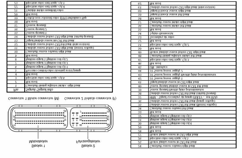
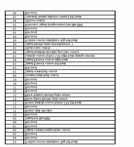
5 ME 9.7 Inputs Outputs 39

6 ME 9.7 Control Module function: Cylinder sequential injection Single spark plug coil (control and diagnostics) Electronic throttle plate positioning LIN communication with alternator Turbulence flap regulation Variable length intake runner control N3/10 ME 9.7 Note: When erasing DTC s you must wait for the after run function to finish otherwise faults may remain. After run process 40
7 ME After Run Process ME performs an after run process when circuit 15 is switched off After run is determined by ME and required to store inputs After run time is typically 5 seconds but can take several minutes longer depending on various functions (temperature management, OBD, DAS3 etc.) at 176 F approx. 4 seconds, at 68 F approx. 60 seconds and at -22 F approx. 150 seconds After cycling key off, must wait ~ 150 seconds This is the period in which the fault memory is over-written 41

8 ME 9.7 Inputs/Outputs Inputs Outputs 42
9 ME 9.7 Inputs/Outputs Legend A16/1 Right knock sensor A16/2 Left knock sensor B2/5 Hot film mass air flow sensor B4/3 Fuel tank pressure sensor B6/4 Left intake camshaft hall sensor B6/5 Right intake camshaft hall sensor B6/6 Left exhaust camshaft hall sensor B6/7 Right exhaust camshaft hall sensor B11/4 Coolant temperature sensor B28 Intake manifold pressure sensor B28/9 Left intake manifold swirl flap position sensor B28/10 Right intake manifold swirl flap position sensor B37 Accelerator pedal sensor B70 Crankshaft hall sensor G2 Alternator G3/3 Left O2 sensor upstream of TWC G3/4 Right O2 sensor upstream of TWC G3/5 Left O2 sensor in TWC G3/6 Right O2 sensor in TWC M16/6 Throttle valve actuator N10/1 Driver SAM N10/1kR Circuit 87 relay N10/1kS Starter relay N10/1kO Air pump relay N10/2 Rear SAM N10/2kA Fuel pump relay S40/3 Clutch pedal switch S40/5 Start enable clutch pedal switch S43 Oil level check switch M4/7 Suction fan T1/1-6 Ignition coils 1 to 6 Y10/1 Power steering pump pressure regulator valve Y22/6 Variable intake manifold switchover valve Y22/9 Intake manifold swirl flap switchover valve Y32 Air pump switchover valve Y49/4 Left camshaft intake solenoid Y49/5 Right camshaft intake solenoid Y49/6 Left camshaft exhaust solenoid Y49/7 Right camshaft exhaust solenoid 43
10 ME 9.7 Network Signals N73 EIS N15/5 Electronic selector lever module control unit A1 Instrument Cluster N47-5 ESP and BAS control unit N80 Steering column module Y3/8n4 Fully integrated transmission control unit X11/4 Diagnostic connector N93 Central gateway control unit N22 AAC control and operating unit N2/7 - Restraint systems control unit 44
11 ME 9.7 Network Signals 45
12 Crank sensor (Hall) O2 sensors Three way catalytic converters Ignition coil Mass airflow 46
 is carry")
13 Crank Sensor Hall effect sensor (not inductive) Output signal switches between ground and 5 volts Incremental ring gear 58 teeth (60 2) is carry over 47
14 Sensor Signals 1 - Crank angle (CKA) 2 - Ignition TDC cylinder (in firing order) 3 - Signal of crankshaft Hall sensor (B70) 4 - Rpm signal TNA 5 - Camshaft Hall sensor intake signal, left and right 6 - Camshaft hall sensor exhaust signal, left and right A = Recognition of ignition TDC of cylinder 1 - second negative signal edge of crankshaft hall sensor after the gap - Signals 5 and 6 are "LOW" - Rpm signal (4) changes from "HIGH to "LOW" 48
 G3/3 Left upstream O2 sensor G3/5 Left downstream O2 sensor 158 Catalytic converter G3/4 Right upstream O2 sensor G3/6 Right downstream O2")
15 O2 Sensors Upstream wide-band O2 sensors as known from the M271 and OM648 Downstream planar type O2 sensors mounted in catalytic converter housing Three Way Catalytic Converters (TWC) G3/3 Left upstream O2 sensor G3/5 Left downstream O2 sensor 158 Catalytic converter G3/4 Right upstream O2 sensor G3/6 Right downstream O2 sensor 49
 Reduces Nitrogen Oxides (NOX) Downstream O2 sensor mounted between the")
16 Three Way Catalytic Converters Two ceramic monoliths with 600 cells each Reduces Hydrocarbons (HC) Reduces Carbon Monoxide (CO) Reduces Nitrogen Oxides (NOX) Downstream O2 sensor mounted between the monoliths 50

17 O2 Sensor Networking 17 Fuel rail 158 Catalytic converter B2/5 Hot film mass airflow sensor B11/4 Coolant temperature sensor B70 Crankshaft hall sensor B37 Accelerator pedal sensor G3/3 Left upstream O2 sensor G3/5 Left downstream O2 sensor G3/4 Right upstream O2 sensor G3/6 Right downstream O2 sensor N3/10 ME 9.7 Y62 Fuel injectors 51

18 Ignition Coil Individual coil on plug Driver located inside coil not in ME 9.7 Each coil controlled separately Diagnostic information sent back to ME Bi-directional communication with ME Pin 1 batt Pin 2 ground Pin 3 ground Pin 4 control/diagnosis 52

19 Ignition Networking A16/1 Right knock sensor A16/2 Left knock sensor B6/4 Left intake camshaft hall sensor B6/5 Right intake camshaft hall sensor B6/6 Left exhaust camshaft hall sensor B6/7 Right exhaust camshaft hall sensor B2/5 Hot film mass airflow sensor B11/4 Coolant temperature sensor B70 Crankshaft hall sensor B37 Accelerator pedal sensor M16/6 Throttle valve actuator N3/10 ME 9.7 N47-5 ESP and BAS control unit T1/1 through T1/6 ignition coil for cylinders 1 to 6 Y3/8n4 - Fully integrated transmission control (VGS) control unit X11/4 Data link connector 53

20 Hot Film Mass Airflow Sensor Frequency signal from Mass Airflow to ME Integrated Intake air temperature sensor used 54
21 Temperature management Thermostat Control 55
 Heating element in thermostat energized to heat")
22 Temperature Management Coolant Temperature is regulated via Me plate thermostat Regulates temperature from 185 F to 221 F (85 C to 105 C) Heating element in thermostat energized to heat thermostat 4 operating modes dependent on engine temperature and load 56
, after start or ambient temp. above 82 F (28 C) D Position for max radiator operation 57")
23 Temperature Management 1 To radiator 2 From engine 3 To engine A Stationary coolant (cold start) B Circuit for engine and heat exchanger C Active after 208 F (98 C), after start or ambient temp. above 82 F (28 C) D Position for max radiator operation 57
24 Temperature Management 58
25 Fuel tank Fuel pump control 59

26 Fuel Tank Magnesium cover helps protect tank Two layer steel tank with 18.4 gallon capacity In tank fuel supply system operates with 3.8 bar pressure Fuel filter with pressure regulator Returnless fuel system 60

27 Fuel Networking A Electrical line B Fuel pipe C Purge line 12 Intake manifold 17 Fuel rail 17/1 Fuel pressure reservoir 45 Fuel filler neck, with ORVR 51 Pressure gauge connection 55/2 Fuel filter 55/2a Fuel pressure regulator 3.8 bar 75 Fuel tank 76 Vent valve, except USA 77 Activated charcoal canister B4/3 Fuel tank pressure sensor M3 Fuel pump assembly (with integral fuel pump (FP)) N10/2kA Fuel pump relay N3/10 ME-SFI control unit Y58/1 Purge control valve Y58/4 Activated charcoal filter shutoff valve Y62 Fuel injection valves 61

28 Fuel Pump Control Fuel pump controlled via fuel pump relay (N10/2kA) Fuel pump Relay located in rear SAM (N10/2) Fuel pump relay energized via ME Fuel pump runs ~ 1 second after ignition on N10/2 Rear SAM N10/2kA Fuel pump relay 62
29 Fuel Supply Circuit In Tank Pressure Regulator (3.8 bar) Fuel Filter Supply Return Splash bowl Fuel Pump Fuel supply to engine 63
30 Access Point To Fuel Filter and Pump Tank Pressure Sensor Connector For pump And level sensor 64

31 Fuel Pressure Regulator Filter Pressure regulator A B C A-from pump B-return to splash bowl C-filtered fuel to engine 65

32 Fuel Level Sensor Release tangs for removal 66

33 Splash Bowl pump Swivel 2 retainers to remove pump 67

34 Fuel Pump 68
35 N3/10 ME 9.7 A1 Instrument cluster N10/2 Rear SAM B4 Fuel level sensor 75 Fuel tank 69
36 Speed Sensitive Power Steering 70
37 Speed Sensitive Power Steering Gives the customer firmer feel in steering at higher speeds and more assist for parking maneuvers at slower speeds ME 9.7 now controls functions of the Speed Sensitive Power Steering system The valve port is adjusted for steering support required for the current driving condition and is dependent on the following input signals: Engine speed Vehicle speed (Via CAN) Steering angle (Via CAN) Steering angle speed (Via CAN) 71
38 Speed Sensitive Power Steering The pressure regulator valve controls the valve port and is rigidly connected to the power steering pump It is actuated according to a performance map with a duty cycle of 10 to 90% and regulates the amount delivered to the power steering pump at between 2 and 9 liters/minute The pressure regulator valve is opened wide for ignition ON and during engine start In the case of faults on the input signals or on the pressure regulator valve, actuation is interrupted immediately and the maximum support is available from the power steering pump 72

39 Speed Sensitive Power Steering Networking B70 Crankshaft Hall sensor N3/10 ME-SFI control unit N47-5 ESP and BAS control unit N80 Steering column module Y10/1 Power steering pump pressure regulator valve 73
40 74
41 75
42 Questions? 76
 PE07.61-P-2001-60DB Legend of block diagram of ME-SFI fuel injection and ignition system ENGINE 271 in MODEL 211 Code Designation Coordinate A1 Instrument cluster 43E A1p13 Multifunction display 42F A7/3
Full list of fault codes and events
 Page 1/7 VIN Order number Model series/model designation License plate 203.747 Full list of fault codes and events P2001 - [1] M16/6 (Throttle valve actuator), Plausibility Position Throttle valve [P0638]
AD07.61-P-4000AC ME-SFI fuel injection and ignition system (ME), DTC memory Possible cause Note Fault code description
, DTC memory Possible cause Note Fault code description") Page 1 of 11 AD07.61-P-4000AC fuel injection and ignition system (ME), DTC memory 14.6.00 ENGINE 112.942 as of 1.6.00 ENGINE 112.970 All tests of the electrical system of the fuel injection system on engine
Page 1 of 11 AD07.61-P-4000AC fuel injection and ignition system (ME), DTC memory 14.6.00 ENGINE 112.942 as of 1.6.00 ENGINE 112.970 All tests of the electrical system of the fuel injection system on engine
9.6 ME-SFI (ME1.0) Engine 120
 Engine 120") Components on engine Model 129 Figure 1 B2/6 Left hot film MAF sensor (located on right side of engine) B2/7 Right hot film MAF sensor (located on left side of engine) B17/5 Left IAT sensor (located in
Components on engine Model 129 Figure 1 B2/6 Left hot film MAF sensor (located on right side of engine) B2/7 Right hot film MAF sensor (located on left side of engine) B17/5 Left IAT sensor (located in
GF07.16-P-9997OGG Overview of system components for common rail diesel injection (CDI)
") GF07.16-P-9997OGG Overview of system components for common rail diesel injection (CDI) 19.12.2016 Engine 642.8 in model 164.1 Engine 642.8 in model 164.8 Engine 642.8 in model 251.0 Engine 642.8 in model
GF07.16-P-9997OGG Overview of system components for common rail diesel injection (CDI) 19.12.2016 Engine 642.8 in model 164.1 Engine 642.8 in model 164.8 Engine 642.8 in model 251.0 Engine 642.8 in model
Test and adjustment values. DTC memory DTC text Possible cause/note Remedy
 AD07.51-P-4000A Fuel injection and ignition system (HFM-SFI) diagnosis, DTC memory 27.2.97 ENGINE 111 a b c d e a b c a b c d Check and adjust engine Fuel injection and ignition system (HFM-SFI) - diagnosis,
Installation location The DME control unit is located in the electronics box on the bulkhead (illustration shows E65).
.") DME control unit: N62TU meeknet.co.uk/e64 Installation location The DME control unit is located in the electronics box on the bulkhead (illustration shows E65). Item Description Item Description 1 Electronics
DME control unit: N62TU meeknet.co.uk/e64 Installation location The DME control unit is located in the electronics box on the bulkhead (illustration shows E65). Item Description Item Description 1 Electronics
5. Control System CONTROL SYSTEM FUEL INJECTION (FUEL SYSTEM) A: GENERAL. FU(STi)-27
 A: GENERAL. FU(STi)-27") W1860BE.book Page 27 Tuesday, January 28, 2003 11:01 PM 5. Control System A: GENERAL The ECM receives signals from various sensors, switches, and other control modules. Using these signals, it determines
W1860BE.book Page 27 Tuesday, January 28, 2003 11:01 PM 5. Control System A: GENERAL The ECM receives signals from various sensors, switches, and other control modules. Using these signals, it determines
5. Control System CONTROL SYSTEM FUEL INJECTION (FUEL SYSTEM) A: GENERAL FU(H4DOTC)-29
 A: GENERAL FU(H4DOTC)-29") W1860BE.book Page 29 Tuesday, January 28, 2003 11:01 PM 5. Control System A: GENERAL The ECM receives signals from various sensors, switches, and other control modules. Using these signals, it determines
W1860BE.book Page 29 Tuesday, January 28, 2003 11:01 PM 5. Control System A: GENERAL The ECM receives signals from various sensors, switches, and other control modules. Using these signals, it determines
5. Engine Control Module (ECM) I/O Signal
 I/O Signal") 5. A: ELECTRICAL SPECIFICATION B134 B135 B136 B137 17 16 15 14 13 12 11 10 9 8 27 26 25 24 23 22 21 20 19 18 34 33 32 31 30 29 28 19 18 17 16 15 14 13 12 11 10 9 8 27 26 25 24 23 22 21 20 35 34 33 32 31
5. A: ELECTRICAL SPECIFICATION B134 B135 B136 B137 17 16 15 14 13 12 11 10 9 8 27 26 25 24 23 22 21 20 19 18 34 33 32 31 30 29 28 19 18 17 16 15 14 13 12 11 10 9 8 27 26 25 24 23 22 21 20 35 34 33 32 31
12/7/2017 Engine Controls (Powertrain Management) - ALLDATA
 - ALLDATA") //0 Engine Controls (Powertrain Management) - ALLDATA 0 Mercedes Benz E 0 Sedan (.0) V-.L (.) Vehicle > Powertrain Management > Diagrams > Electrical - Interactive Color (Non OE) Engine Controls - Page
//0 Engine Controls (Powertrain Management) - ALLDATA 0 Mercedes Benz E 0 Sedan (.0) V-.L (.) Vehicle > Powertrain Management > Diagrams > Electrical - Interactive Color (Non OE) Engine Controls - Page
Diagnostic Trouble Code (DTC) memory, checking and erasing
 memory, checking and erasing") Page 1 of 49 01-12 Diagnostic Trouble Code (DTC) memory, checking and erasing Check DTC Memory (function 02) - Connect VAS5051 tester Page 01-7 and select vehicle system "01 - Engine electronics". Engine
Page 1 of 49 01-12 Diagnostic Trouble Code (DTC) memory, checking and erasing Check DTC Memory (function 02) - Connect VAS5051 tester Page 01-7 and select vehicle system "01 - Engine electronics". Engine
512 HO M285 Engine (FrechW) Maybach Engine M285
 Maybach Engine M285") 512 HO M285 Engine (FrechW) 08-06-03 Maybach Engine M285 These technical training materials are current as of the date noted on the materials, and may be revised or updated without notice. Always check
512 HO M285 Engine (FrechW) 08-06-03 Maybach Engine M285 These technical training materials are current as of the date noted on the materials, and may be revised or updated without notice. Always check
EMISSION CONTROL (AUX. EMISSION CONTROL DEVICES) H4DOTC
 H4DOTC") EMISSION CONTROL (AUX. EMISSION CONTROL DEVICES) H4DOTC SYSTEM OVERVIEW 1. System Overview There are three emission control systems, which are as follows: Crankcase emission control system Exhaust emission
EMISSION CONTROL (AUX. EMISSION CONTROL DEVICES) H4DOTC SYSTEM OVERVIEW 1. System Overview There are three emission control systems, which are as follows: Crankcase emission control system Exhaust emission
DIAGNOSTIC TROUBLE CODE CHART HINT:
 DIAGNOSTICS DIAGNOSTIC TROUBLE CODE CHART HINT: SFI SYSTEM (1MZFE) 05241 Parameters listed in the chart may not be exactly the same as your reading due to the type of instrument or other factors. If a
Powertrain DTC Summaries EOBD
 Powertrain DTC Summaries Quick Reference Diagnostic Guide Jaguar X-TYPE 2.0 L 2002.25 Model Year Refer to page 2 for important information regarding the use of Powertrain DTC Summaries. Jaguar X-TYPE 2.0
Federal and California Emissions Warranties Parts List
 Emissions warranties are state specific. Refer to the years/miles 1 columns below as follows: A Minimum coverage for all vehicles in all states. B Vehicles registered and normally operated in California,
E - THEORY/OPERATION - TURBO
 E - THEORY/OPERATION - TURBO 1995 Volvo 850 1995 ENGINE PERFORMANCE Volvo - Theory & Operation 850 - Turbo INTRODUCTION This article covers basic description and operation of engine performance-related
A: ENGINE CONTROL MODULE (ECM) I/O SIGNAL FOR MT VEHICLES. Signal (V) Ignition SW ON (Engine OFF) B B B
 I/O SIGNAL FOR MT VEHICLES. Signal (V) Ignition SW ON (Engine OFF) B B B") 5. Specified Data A: ENGINE CONTROL MODULE (ECM) I/O SIGNAL FOR MT VEHICLES B2M2267A Crankshaft Camshaft Throttle Rear oxygen Front oxygen (A/F) heater Rear oxygen heater Engine coolant temperature Signal
5. Specified Data A: ENGINE CONTROL MODULE (ECM) I/O SIGNAL FOR MT VEHICLES B2M2267A Crankshaft Camshaft Throttle Rear oxygen Front oxygen (A/F) heater Rear oxygen heater Engine coolant temperature Signal
Powertrain DTC Summaries EOBD
 Powertrain DTC Summaries Quick Reference Diagnostic Guide Jaguar S-TYPE V6, V8 N/A and V8 SC 2002.5 Model Year Refer to pages 2 9 for important information regarding the use of Powertrain DTC Summaries.
MERCEDES P1XXX CODES Gas and Diesel
 MERCEDES P1XXX CODES 4/27/2000 Gasoline Engines Mercedes Pcode P0801 P1031 P1131 P1132 P1137 P1138 P1146 MERCEDES P1XXX CODES Gas and Diesel OBD-II Pcode Definition Engine/Climate control electric cooling
Data Unit Value Coolant temperature 0.436V (130 ) ~4.896V (-40 )
 ~4.896V (-40 )") 149000 153 1. ENGINE DATA LIST Data Unit Value Coolant temperature 0.436V (130 ) ~4.896V (40 ) Intake air temperature 40~130 (varies according to ambient air temperature or engine mode) Idle speed rpm
149000 153 1. ENGINE DATA LIST Data Unit Value Coolant temperature 0.436V (130 ) ~4.896V (40 ) Intake air temperature 40~130 (varies according to ambient air temperature or engine mode) Idle speed rpm
EMISSION CONTROL (AUX. EMISSION CONTROL DEVICES) H4SO
 H4SO") EMISSION CONTROL (AUX. EMISSION CONTROL DEVICES) H4SO SYSTEM OVERVIEW 1. System Overview There are three emission control systems, which are as follows: Crankcase emission control system Exhaust emission
EMISSION CONTROL (AUX. EMISSION CONTROL DEVICES) H4SO SYSTEM OVERVIEW 1. System Overview There are three emission control systems, which are as follows: Crankcase emission control system Exhaust emission
EMISSION CONTROL (AUX. EMISSION CONTROL DEVICES) H6DO
 H6DO") EMISSION CONTROL (AUX. EMISSION CONTROL DEVICES) H6DO SYSTEM OVERVIEW 1. System Overview There are three emission control systems, which are as follows: Crankcase emission control system Exhaust emission
EMISSION CONTROL (AUX. EMISSION CONTROL DEVICES) H6DO SYSTEM OVERVIEW 1. System Overview There are three emission control systems, which are as follows: Crankcase emission control system Exhaust emission
DIAGNOSTIC TROUBLE CODE CHART
 DIAGNOSTIC TROUBLE CODE CHART HINT: DI231 Parameters listed in the chart may not be exactly the same as your readings due to the type of instrument or other factors. If a malfunction code is displayed
Engine Management for the Phaeton W12 Engine
 Service. Self-Study Programme 250 Engine Management for the Phaeton W12 Engine Design and Function The Motronic engine management system for the W12 engine allows high engine performance with low fuel
Audi A4 Current Flow Diagram No. 44 / 1 Edition
 Page 1 of 16 Audi A4 Current Flow Diagram No. 44 / 1 Edition 05.2003 1.8 l - Fuel injection engine (110 kw - Motronic - 4 cylinder), engine code AVJ from model year 2002 1.8 l - Fuel injection engine (120
Diagnostic Trouble Code (DTC) table
 table") Page 1 of 40 01-19 Diagnostic Trouble Code (DTC) table Note: When malfunctions occur in monitored sensors or components, Diagnostic Trouble Codes (DTCs) are stored in DTC memory with a description of the
Page 1 of 40 01-19 Diagnostic Trouble Code (DTC) table Note: When malfunctions occur in monitored sensors or components, Diagnostic Trouble Codes (DTCs) are stored in DTC memory with a description of the
DIAGNOSTIC TROUBLE CODE DEFINITIONS
 DIAGNOSTIC TROUBLE CODE DEFINITIONS DIAGNOSTIC TROUBLE CODE DEFINITIONS DTC Description P0010 Variable Valve Timing Circuit Malfunction (Bank 1) P0020 Variable Valve Timing Circuit Malfunction (Bank 2)
5. Engine Control Module (ECM) I/O Signal S008526
 I/O Signal S008526") 5. Engine Control Module (ECM) I/O Signal S008526 A: ELECTRICAL SPECIFICATION S008526A08 1. MT VEHICLES S008526A0801 B2M2267A Crankshaft Camshaft Throttle Rear oxygen Front oxygen (A/F) heater Rear oxygen
5. Engine Control Module (ECM) I/O Signal S008526 A: ELECTRICAL SPECIFICATION S008526A08 1. MT VEHICLES S008526A0801 B2M2267A Crankshaft Camshaft Throttle Rear oxygen Front oxygen (A/F) heater Rear oxygen
Copyright DaimlerChrysler AG CD-Ausgabe G/11/05. This WIS print-out will not be recorded by Modification services.
 Copyright DaimlerChrysler AG 03.12.2005 CD-Ausgabe G/11/05. This WIS print-out will not be recorded by Modification services. Page 3 Copyright DaimlerChrysler AG 03.12.2005 CD-Ausgabe G/11/05. This WIS
Fuel Supply & ME-SFI Engine Management Emission Systems (Part 12) 508 HO Part 12 - Emission systems (WJB)
 508 HO Part 12 - Emission systems (WJB)") Fuel Supply & ME-SFI Engine Management Emission Systems (Part 12) 508 HO Part 12 - Emission systems (WJB) 04-01-01 1 These technical training materials are current as of the date noted on the materials,
Fuel Supply & ME-SFI Engine Management Emission Systems (Part 12) 508 HO Part 12 - Emission systems (WJB) 04-01-01 1 These technical training materials are current as of the date noted on the materials,
Fuel Metering System Component Description
 1999 Chevrolet/Geo Tahoe - 4WD Fuel Metering System Component Description Purpose The function of the fuel metering system is to deliver the correct amount of fuel to the engine under all operating conditions.
The 1.4 ltr. and 1.6 ltr. FSI engine with timing chain
 Service. Self study programme 296 The 1.4 ltr. and 1.6 ltr. FSI engine with timing chain Design and function For Volkswagen, new and further development of engines with direct petrol injection is an important
Powertrain DTC Summaries EOBD
 Powertrain DTC Summaries Quick Reference Diagnostic Guide Jaguar X-TYPE 2.5L and 3.0L 2001.5 Model Year Revised January, 2002: P0706, P0731, P0732, P0733, P0734, P0735, P0740, P1780 POSSIBLE CAUSES Revised
1.2 HFM Sequential Multiport Fuel injection/ignition System (HFM-SFI) Engine 111
 Engine 111") Preliminary work: Diagnosis - Malfunction Memory...................................... 11 Preparation for Test 1. Ignition: OFF 2. Connect test cable with socket box to engine control module (N3/4) according
Preliminary work: Diagnosis - Malfunction Memory...................................... 11 Preparation for Test 1. Ignition: OFF 2. Connect test cable with socket box to engine control module (N3/4) according
Powertrain DTC Summaries OBD II
 Powertrain DTC Summaries Quick Reference Diagnostic Guide Jaguar X-TYPE 2.5L and 3.0L 2002 Model Year Revised January, 2002: P0706, P0731, P0732, P0733, P0734, P0735, P0740, P1780 POSSIBLE CAUSES Revised
ON-BOARD DIAGNOSTICS II SYSTEM. 5. Specified Data. Signal (V) Ignition SW ON (Engine OFF)
 Ignition SW ON (Engine OFF)") 1. ENGINE CONTROL MODULE (ECM) I/O SIGNAL OBD0092A Crankshaft Camshaft Mass air flow Throttle Signal (+) 8 0 7 +7 Sensor output waveform Signal ( ) 29 0 0 Shield 54 0 0 Signal (+) 7 0 7 +7 Sensor output
1. ENGINE CONTROL MODULE (ECM) I/O SIGNAL OBD0092A Crankshaft Camshaft Mass air flow Throttle Signal (+) 8 0 7 +7 Sensor output waveform Signal ( ) 29 0 0 Shield 54 0 0 Signal (+) 7 0 7 +7 Sensor output
E - THEORY/OPERATION ENGINE PERFORMANCE General Motors Corp. - Theory & Operation - 5.7L
 E - THEORY/OPERATION 1998 ENGINE PERFORMANCE General Motors Corp. - Theory & Operation - 5.7L INTRODUCTION This article covers basic description and operation of engine performance-related systems and
Fig.11 Powertrain Control Module (PCM)
") 2003 Dodge or Ram Truck Caravan V6-3.3L VIN R Vehicle > Powertrain Management > Relays and Modules - Powertrain Management > Relays and Modules - Computers and Control Systems > Engine Control Module >
2003 Dodge or Ram Truck Caravan V6-3.3L VIN R Vehicle > Powertrain Management > Relays and Modules - Powertrain Management > Relays and Modules - Computers and Control Systems > Engine Control Module >
5. Engine Control Module (ECM) I/O Signal
 I/O Signal") 5. Engine Control Module (ECM) I/O Signal A: ELECTRICAL SPECIFICATION B134 B135 B136 B137 17 16 15 14 13 12 11 10 9 8 27 26 25 24 23 22 21 20 19 18 34 33 32 31 30 29 28 19 18 17 16 15 14 13 12 11 10 9
5. Engine Control Module (ECM) I/O Signal A: ELECTRICAL SPECIFICATION B134 B135 B136 B137 17 16 15 14 13 12 11 10 9 8 27 26 25 24 23 22 21 20 19 18 34 33 32 31 30 29 28 19 18 17 16 15 14 13 12 11 10 9
!"#$%&'()*+(,%&%-)-".&(/01*%)$"%&2(#2$&3456. This can be found in the camshaft housing and is included in the oil circuit of the engine.
*+(,%&%-)-.&(/01*%)$%&2(#2$&3456. This can be found in the camshaft housing and is included in the oil circuit of the engine.") !"#$%&'()*+(,%&%-)-".&(/01*%)$"%&2(#2$&3456 This can be found in the camshaft housing and is included in the oil circuit of the engine. Actuation of the inlet camshaft timing adjustment valve results in
!"#$%&'()*+(,%&%-)-".&(/01*%)$"%&2(#2$&3456 This can be found in the camshaft housing and is included in the oil circuit of the engine. Actuation of the inlet camshaft timing adjustment valve results in
Motronic September 1998
 The Motronic 1.8 engine management system was introduced with the 1992 Volvo 960. The primary difference between this Motronic system and the previous generation of Volvo LH-Jetronic engine management
Service Bulletin. DTC Detection Item Associated Monitor
 Service Bulletin 03-010 Applies To: All OBD II equipped models except SLX March 29, 2003 OBD II DTCs and Their Associated Monitors This is a list of all DTCs for all OBD II models. No one model has all
2UZ-FE ENGINE. Engine Control System TOYOTA TUNDRA - NEW FEATURES
 2UZ-FE ENGINE Engine Control System General The engine control system of the 2UZ-FE engine on the 06 has following systems. System SFI Sequential Multiport Fuel Injection ESA Electronic Spark Advance ETCS-i
Audi A3 Current Flow Diagram No. 75 / 1 Edition Audi A3 (1,8 l litre fuel injection engine, 110 kw, Motronic, 4-cylinder) engine codes AQA
 engine codes AQA") Strona 1 z 10 Audi A3 Current Flow Diagram No. 75 / 1 Edition 09.1999 Audi A3 (1,8 l litre fuel injection engine, 110 kw, Motronic, 4-cylinder) engine codes AQA From model year 1999 Audi A3 (1,8 l litre
Strona 1 z 10 Audi A3 Current Flow Diagram No. 75 / 1 Edition 09.1999 Audi A3 (1,8 l litre fuel injection engine, 110 kw, Motronic, 4-cylinder) engine codes AQA From model year 1999 Audi A3 (1,8 l litre
Auto Diagnosis Test #7 Review
 Auto Diagnosis Test #7 Review Your own hand written notes may be used for the 1 st 10 minutes of the test Based on Chapters 25, 26, 32, 33, 34 and Lab Demonstrations Auto Diagnosis Test #7 Review Your
OBD-II Diagnostic Powertrain (P) Trouble Codes
 Trouble Codes") OBD-II Diagnostic Powertrain (P) Trouble Codes Please use our new & improved search engine to find information on your trouble codes. Search Now! This list contains standard diagnostic trouble codes (DTC
OBD-II Diagnostic Powertrain (P) Trouble Codes Please use our new & improved search engine to find information on your trouble codes. Search Now! This list contains standard diagnostic trouble codes (DTC
Error codes Diagnostic plug Read-out Reset Signal Error codes
 Error codes Diagnostic plug Diagnostic plug: 1 = Datalink LED tester (FEN) 3 = activation error codes (TEN) 4 = positive battery terminal (+B) 5 = ground Read-out -Connect LED tester to positive battery
2.8 Liter VR6 2V Fuel Injection & Ignition, Engine Code(s): AAA m.y
: AAA m.y") 2.8 Liter VR6 2V Fuel Injection & Ignition, Engine Code(s): AAA m.y. 1996-1997 01 - On Board Diagnostic (OBD) On Board Diagnostic (OBD II) Malfunction Indicator Lamp (MIL) On Board Diagnostic (OBD II),
2.8 Liter VR6 2V Fuel Injection & Ignition, Engine Code(s): AAA m.y. 1996-1997 01 - On Board Diagnostic (OBD) On Board Diagnostic (OBD II) Malfunction Indicator Lamp (MIL) On Board Diagnostic (OBD II),
Common rail injection system
 Common rail injection system Pressure limiting valve The pressure limiting valve is located directly on the high-pressure fuel rail. Its function is to limit maximum pressure in the high-pressure fuel
DTC P0300 Random / Multiple Cylinder Misfire Detected. DTC P0301 Cylinder 1 Misfire Detected. DTC P0302 Cylinder 2 Misfire Detected
 1GR-FE EINE CONTROL SYSTEM SFI SYSTEM 169 DTC P0300 Random / Multiple Cylinder Misfire Detected DTC P0301 Cylinder 1 Misfire Detected DTC P0302 Cylinder 2 Misfire Detected DTC P0303 Cylinder 3 Misfire
3.2 LH Sequential Multiport Fuel Injection System (LH-SFI) Engine 120
 Engine 120") Preliminary work: Diagnosis - Diagnostic Trouble Code (DTC) Memory.......................... 11 Preparation for Test 1. Ignition: OFF 2. Remove LH-SFI control module (N3/2 or N3/3). 3. After determining
Preliminary work: Diagnosis - Diagnostic Trouble Code (DTC) Memory.......................... 11 Preparation for Test 1. Ignition: OFF 2. Remove LH-SFI control module (N3/2 or N3/3). 3. After determining
E60, E61, E63, E64, E65, E66, E70 BMW AG - TIS
 VS-42 je Baugruppe/Group: 11 meeknet.co.uk/e64 11 03 05 (142) 8-cylinder spark-ignition engine N62TU E60, E61, E63, E64, E65, E66, E70 weltweit Datum/Date: 04/2007 Update: 04/2007 Introduction The N62TU
DTC Summaries. NipponDenso V12 Engine Management
 DTC Summaries NipponDenso V12 Engine Management OBD II MONITORING CONDITIONS: When testing for DTC reoccurrence, it can be determined if the Service Drive Cycle was of sufficient length by performing a
Diagnostic Trouble Code (DTC) List - Vehicle
 List - Vehicle") Document ID# 850406 2002 Pontiac Firebird Diagnostic Trouble Code (DTC) List - Vehicle DTC DTC 021 and/or 031 DTC 022 and/or 032 DTC 023 or 033 DTC 24/34 DTC 025 and/or 035 DTC 041 DTC 042 DTC 043 DTC
Document ID# 850406 2002 Pontiac Firebird Diagnostic Trouble Code (DTC) List - Vehicle DTC DTC 021 and/or 031 DTC 022 and/or 032 DTC 023 or 033 DTC 24/34 DTC 025 and/or 035 DTC 041 DTC 042 DTC 043 DTC
!"#$%&'$()*&$+,-$%&.$()*&$/01$#,23,# 43)"$)353,2$6"+3,
*&$+,-$%&.$()*&$/01$#,23,# 43)$)353,2$6+3,") 0#*?36#& 0#(7$8)9-:$;*.!"#$%&'$()*&$+,-$%&.$()*&$/01$#,23,# 43)"$)353,2$6"+3, Design and function For Volkswagen, new and further development of engines with direct petrol injection is an important
0#*?36#& 0#(7$8)9-:$;*.!"#$%&'$()*&$+,-$%&.$()*&$/01$#,23,# 43)"$)353,2$6"+3, Design and function For Volkswagen, new and further development of engines with direct petrol injection is an important
Transmission Electronic Control System
 SECTION 307-01: Automatic Transaxle/Transmission 5R55S 2009 Mustang Workshop Manual DESCRIPTION AND OPERATION Procedure revision date: 05/23/2008 Transmission Electronic Control System Electronic System
Full list of fault codes and events
 Sunday, August 13, 2017 17:39:41 Page 1/7 \AddOns: ([6988) (7160) (7258) (6755) (6933) (7418) (7176) (6765) (7292) (6726) (6832) (7030) (6815) (6961) (6892) (6927) (6642) (6882) (6977) (6604) (7100) (7128)
MULTIPORT FUEL SYSTEM (MFI) <2.4L ENGINE>
 <2.4L ENGINE>") 13B-1 GROUP 13B MULTIPORT FUEL SYSTEM (MFI) CONTENTS GENERAL DESCRIPTION 13B-2 CONTROL UNIT 13B-5 SENSOR 13B-7 ACTUATOR 13B-24 FUEL INJECTION CONTROL 13B-31 IGNITION TIMING AND CONTROL FOR
13B-1 GROUP 13B MULTIPORT FUEL SYSTEM (MFI) CONTENTS GENERAL DESCRIPTION 13B-2 CONTROL UNIT 13B-5 SENSOR 13B-7 ACTUATOR 13B-24 FUEL INJECTION CONTROL 13B-31 IGNITION TIMING AND CONTROL FOR
14. Engine Control System
 48 4. Engine Control System General The engine control system of the 2GR-FE engine has the following features. The Engine ECU that controls this system is made by DENSO. System EFI (Electric Fuel Injection)
DIAGNOSTIC TROUBLE CODE CHART
 DIAGNOSTIC TROUBLE CODE CHART 05 35 HINT: As for the vehicle for MEXICO, refer to Repair Manual 2003 COROLLA MATRIX (Pub. No. RM940U). Parameters listed in the chart may not be exactly the same as your
ENGINE AND EMISSION CONTROL
 17-1 GROUP 17 ENGINE AND EMISSION CONTROL CONTENTS ENGINE CONTROL 17-2 GENERAL INFORMATION 17-2 AUTO-CRUISE CONTROL SYSTEM 17-3 GENERAL INFORMATION 17-3 CONSTRUCTION AND OPERATION 17-5 17-7 GENERAL INFORMATION
2AZ-FE ENGINE CONTROL SYSTEM SFI SYSTEM TERMINALS OF ECM. Terminal No. (Symbols) Wiring Color Terminal Description Condition Specified Condition
 Wiring Color Terminal Description Condition Specified Condition") 2AZ-FE ENGINE CONTROL SYSTEM SFI SYSTEM 29 TERMINALS OF ECM E8 E7 E5 E4 A066714E10 The standard normal voltage between each pair of the ECM terminals is shown in the table below. The appropriate conditions
2AZ-FE ENGINE CONTROL SYSTEM SFI SYSTEM 29 TERMINALS OF ECM E8 E7 E5 E4 A066714E10 The standard normal voltage between each pair of the ECM terminals is shown in the table below. The appropriate conditions
3. Engine Control System Diagram
 ENGINE - 2UZ-FE ENGINE 59 3. Engine Control System Diagram Ignition Switch Fuel Pump Relay Fuel Pump Resister Circuit Opening Fuel Relay Filter Intake Temp. Mass Air Flow Meter Throttle Position Fuel Pump
 http://www.prodemand.com/print/index?content=tabs&module=true&tab=true&terms=t... Page of // 0 Chevrolet Traverse.L Eng LT Service Manual: WIRING DIAGRAMS Print Date: // ENGINE PERFORMANCE >.L VIN D Fig
ENGINE MANAGEMENT SYSTEM. System Sensors
 ENGINE MANAGEMENT SYSTEM System Sensors Throttle position sensor - Used to relay throttle position information to the ECU. Throttle opening angle is used by the ECU to determine fuelling and ignition requirements
1.2 HFM Sequential Multiport Fuel Injection/Ignition System (HFM-SFI) Engine 111
 Engine 111") Diagnosis - Diagnostic Trouble Code () Memory Preliminary work:........................ Engine Test, djustment, Engines, Volume 1 Note regarding diagnostic trouble code () readout: The engine control module
Diagnosis - Diagnostic Trouble Code () Memory Preliminary work:........................ Engine Test, djustment, Engines, Volume 1 Note regarding diagnostic trouble code () readout: The engine control module
Code Scanner CS1000 OB Table of Contents. Rick's Mercedes Benz Ground Positive Test
 Mercedes Benz Code Scanner CS1000 OB15-11 Table of Contents Rick's OBD1 OBD1 Diagnostic Diagnostic Code Code Reader Reader Manual Mercedes Benz 1988-1995 Locate your diagnostic socket Ground Positive Test
VOLKS CITY BEECH AVENUE CATTEDOWN PLYMOUTH PL4 0QQ
 VOLKS CITY BEECH AVENUE CATTEDOWN PLYMOUTH PL4 0QQ Telephone: 01752 667007 Fax: 01752 663399 Email: mail@volkscity.com 1 Camshaft position (CMP) sensor 1 2 Camshaft position (CMP) sensor 2 3 Camshaft position
Motronic injection system,
 Page 1 of 78 24-1 Motronic injection system, servicing Safety precautions If special testing equipment is required during road test, note the following: WARNING! Scan tools and testing devices must always
EMISSION CONTROL EMISSION CONTROLS
 EMISSION CONTROL EMISSION CONTROLS Emissions control systems on Land Rover vehicles work closely with fuel system controls to reduce airborne pollutants. Improper operation of these systems can lead to
ProECU Subaru DIT. DTC List 2012-onward Model Year. v1.0
 ProECU Subaru DIT DTC List 2012-onward Model Year v1.0 Engine DTC List P000A A CAMSHAFT POSITION SLOW RESPONSE (BANK 1) P000B B CAMSHAFT POSITION SLOW RESPONSE (BANK 1) P000C A CAMSHAFT POSITION SLOW RESPONSE
1995 Nissan Altima ECU
 by jserrano (www.nissanclub.com) 1995 Nissan Altima ECU Pin Color Name Symbol Description Signal Rev. 0.6 1 W Ignition Signal IGN This pulse signal drives the base of the ignition power transistor and
Lotus Service Notes Section EMD
 ENGINE MANAGEMENT SECTION EMD Lotus Techcentre Sub-Section Page Diagnostic Trouble Code List EMD.1 3 Component Function EMD.2 8 Component Location EMD.3 10 Diagnostic Guide EMD.4 11 CAN Bus Diagnostics;
VW 3.2 and 3.6 liter FSI Engine
 Service Training Self Study Program 823603 VW 3.2 and 3.6 liter FSI Engine Volkswagen of America, Inc. Volkswagen Academy Printed in U.S.A. Printed 10/2006 Course Number 823603 2006 Volkswagen of America,
Engine Systems. Basic Engine Operation. Firing Order. Four Stroke Cycle. Overhead Valves - OHV. Engine Design. AUMT Engine Systems 4/4/11
 Advanced Introduction Brake to Automotive Systems Diagnosis Service and Service Basic Engine Operation Engine Systems Donald Jones Brookhaven College The internal combustion process consists of: admitting
9.2 ME - SFI (ME2.1) Engine 111
 Engine 111") Diagnosis - Diagnostic Trouble Code () Memory Preliminary work:............. Engine Test, djustment, Engines (SMS, Job No. 07-1100) M WRNING! Risk of severe injury when touching ignition parts which produce
Diagnosis - Diagnostic Trouble Code () Memory Preliminary work:............. Engine Test, djustment, Engines (SMS, Job No. 07-1100) M WRNING! Risk of severe injury when touching ignition parts which produce
1996 Nissan Altima ECU
 by jserrano (www.nissanclub.com) 1996 Nissan Altima ECU Pin Color Name Symbol Description Signal Rev. 0.5 1 W Ignition Signal IGN This pulse signal drives the base of the ignition power transistor and
ENGINE 1UZ-FE ENGINE 45. System Outline GS LS400 SFI
 ENGINE 1UZ-FE ENGINE 45 ENGINE CONTROL SYSTEM 1. General The engine control system of the new 1UZ-FE engine is basically same in construction and operation as that of the 1UZ-FE engine for the 98 LS400.
ENGINE AND EMISSION CONTROL
 17-1 ENGINE AND EMISSION CONTROL CONTENTS ENGINE CONTROL SYSTEM........ 3 SERVICE SPECIFICATION............... 3 ON-VEHICLE SERVICE.................. 3 Accelerator Cable Check and Adjustment... 3 ACCELERATOR
9.2 ME - SFI Contents
 9.2 M - SFI Contents 9.2 ngine 111 as of 08/96 Diagnosis Page Diagnostic Trouble Code (DTC) Memory................ 11/1 Complaint Related Diagnostic Chart................... 12/1 Fuel Pump Test Page Preparation
Kubota Engine Training: WG1605, spark ignited
 Kubota Engine Training: WG1605, spark ignited WG1605 Engine Training: System Overviews Mechanical Components Electronic Components and Sensors Operation Service Tool Fuel System Overview: Fuel System Overview:
DIAGNOSTIC TROUBLE CODE CHART
 DI158 DIAGNOSTIC TROUBLE CODE CHART HINT: ENGINE (2JZGTE) Parameters listed in the chart may not be exactly the same as your reading due to the type of instrument or other factors. If a malfunction code
EMISSION CONTROL SYSTEMS
 TJ EMISSION CONTROL SYSTEMS 25-1 EMISSION CONTROL SYSTEMS CONTENTS page page EVAPORATIVE EMISSION CONTROLS... 20 ON-BOARD DIAGNOSTICS... 1 ON-BOARD DIAGNOSTICS INDEX page DESCRIPTION AND OPERATION CIRCUIT
DIAGNOSTIC TROUBLE CODE CHART (SAE Controlled)
") 1MZFE ENGINE EG2404 (SAE Controlled) HINT: Parameters listed in the chart may not be exactly the same as your reading due to the type of instrument or other factors. DTC No. Detection Item Diagnostic Trouble
1MZFE ENGINE EG2404 (SAE Controlled) HINT: Parameters listed in the chart may not be exactly the same as your reading due to the type of instrument or other factors. DTC No. Detection Item Diagnostic Trouble
EMISSION CONTROL VISUAL INSPECTION PROCEDURES
 EMISSION CONTROL VISUAL INSPECTION PROCEDURES 1992 Infiniti G20 1983-98 GENERAL INFORMATION Emission Control Visual Inspection Procedures All Models * PLEASE READ THIS FIRST * This article is provided
MULTIPOINT FUEL INJECTION (MPI) <4G9>
 <4G9>") MULTIPOINT FUEL INJECTION (MPI) 13C-1 MULTIPOINT FUEL INJECTION (MPI) CONTENTS GENERAL................................. 2 Outline of Changes............................ 2 GENERAL INFORMATION...................
MULTIPOINT FUEL INJECTION (MPI) 13C-1 MULTIPOINT FUEL INJECTION (MPI) CONTENTS GENERAL................................. 2 Outline of Changes............................ 2 GENERAL INFORMATION...................
Lotus Service Notes Section EMR
 ENGINE MANAGEMENT SECTION EMR Lotus Techcentre Sub-Section Page Diagnostic Trouble Code List EMR.1 3 Component Function EMR.2 7 Component Location EMR.3 9 Diagnostic Guide EMR.4 11 CAN Bus Diagnostics;
ProECU Subaru BRZ Toyota GT86 Scion FR-S
 ProECU Subaru BRZ Toyota GT86 Scion FR-S DTC List 2012-onward Model Year v1.0 Engine DTC List P000A Camshaft Position "A" - Timing Slow Response Bank 1 P000B Camshaft Position "B" - Timing Slow Response
9.6 ME-SFI Contents. b Diagnostic Manual Engines 10/ ME - SFI C/ Engine 120. Fuel Pump Test Preparation for Test... 33/1 Test...
 9.6 M-SFI Contents 9.6 ngine 120 Diagnosis Page Diagnostic Trouble Code (DTC) Memory................ 11/1 Complaint Related Diagnostic Chart................... 12/1 Trouble Code Description..........................
ENGINE CONTROL SYSTEM. 1. General EG-26 ENGINE 2UZ-FE ENGINE. The engine control system for the 2UZ-FE engine has following system.
 EG-26 ENGINE 2UZ-FE ENGINE ENGINE CONTROL SYSTEM 1. General The engine control system for the 2UZ-FE engine has following system. System SFI (Sequential Multiport Fuel Injection) ESA (Electronic Spark
Audi A4 Current Flow Diagram No. 4 / 1 Edition
 Стр. 1 из 11 Audi A4 Current Flow Diagram No. 4 / 1 Edition 10.2001 Audi A4 (1.8 litre fuel injection engine, 110 kw, Motronic (5-valve/turbo), 4-cylinder), engine codes APU/ANB From model year 2000 Audi
Service. The 6.0 l W12 engine in the Audi A8 - Part 2. Self-study programme 268. For internal use only
 268 Service. The 6.0 l W12 engine in the Audi A8 - Part 2 Self-study programme 268 For internal use only Contents Engine, Mechanics Page Belt drive/ancillaries...................................................
4.0L CEC SYSTEM Jeep Cherokee DESCRIPTION OPERATION FUEL CONTROL DATA SENSORS & SWITCHES
 4.0L CEC SYSTEM 1988 Jeep Cherokee 1988 COMPUTERIZED ENGINE Controls ENGINE CONTROL SYSTEM JEEP 4.0L MPFI 6-CYLINDER Cherokee, Comanche & Wagoneer DESCRIPTION The 4.0L engine control system controls engine
COMPONENT LOCATIONS GROUP CONTENTS FUSIBLE LINK, FUSE AND IOD OR STORAGE CONNECTOR RELAY OTHER DEVICES...
 70-1 GROUP 70 COMPONENT LOCTIONS CONTENTS RELY........................ 70-2 OTHER DEVICES............... 70-3 CONTROL UNIT................. 70-4 INSPECTION TERMINL......... 70-7 SENSOR.......................
Engine mechanics. Crankcase ventilation outlet
 Engine mechanics Crankcase ventilation outlet The gases are drawn out of the crankcase by the vacuum in the intake manifold. The oil is separated from the gases in the labyrinth and in the cyclone oil
ME Objectives of the Module...2 Purpose of the System...3 System Components...4
 Table of Contents Subject Page ME 9.2....................................................2 Objectives of the Module.....................................2 Purpose of the System.......................................3
 Page 1 of 6 Section 03-01C: Engine, 7.5L MFI 1996 Bronco/F-Series Workshop Manual IN-VEHICLE SERVICE Procedure revision date: 06/19/2000 Cylinder Heads Removal SPECIAL SERVICE TOOL(S) REQUIRED Description
DTC P0300 Random / Multiple Cylinder Misfire Detected
 162 DTC P0300 Random / Multiple Cylinder Misfire Detected DTC P0301 Cylinder 1 Misfire Detected DTC P0302 Cylinder 2 Misfire Detected DTC P0303 Cylinder 3 Misfire Detected DTC P0304 Cylinder 4 Misfire