WELDING POSITIONER S OPERATION MANUAL CWP40
|
|
|
- Conrad West
- 5 years ago
- Views:
Transcription
1 WELDING POSITIONER S OPERATION MANUAL CWP40 Revision May Note: The information contained in this manual is intended to be accurate. However the manufacturer retain the rights to make changes in design which may not be include herein Page # 1
2 Table of Content IRIZAR HEAVY INDUSTRIES INC 1.0 Welding Positioners Description 3 Welding Positioner CWP Installation Instructions 5 Remote Control Box Operation 10 Main Control Box Operation 10 Tilt Brake Lubrication and Preventive Maintenances 13 Gearboxes 13 Open Gears 14 Bearings Warnings Troubleshooting Procedures 17 Procedure to Re-Setting VFD (N2-200/400) Technical Documentation 19 CWP 40 Foundation Drawing 19 CWP 40 Assembling Instructions 20 CWP 40 General Dimensions 21 CWP 40 Electrical Diagram 22 CWP 40 Capacity Chart 23 CWP 40 Data Plate 24 CWP 40 Table Drawings 25 CWP 40 Part List Drawing 28 CWP 40 Part List Description 29 CWP 40 Material Documentation 30 CWP 40 Electrical Part List Limited Warranty 36 Page # 2


3 1.0 Welding Positioners Description Welding Positioner s are a state of art equipment designed and used to allow welding positioning of various shape work pieces. The positioners have variable table rotational speed through the use of a remote control box and tilt thought the main control box. Welding Positioner CWP 40 Standard package: Max Load 90 degrees 40 1,200 mm GC 34 1,400 mm GC 30 1,600 mm GC 26 1,800 mm GC 24 2,000 mm GC 21 2,200 mm GC Max Eccentricity: 300 mm Rotation Torque: 142,000 N-m Tilt Torque: 500,000 N-m Tilt Angle from degrees Rotation Motor: no. Tilt Motor: no. Rotation Speed from to 0.50 RPM Tilt Speed from to 0.10 RPM Drop Off: 600 mm (from rotation center to top extension arms) Max work piece diameter: 3.90 m Octagonal table with inscribed circumference of 2.2 m Ø Extension arms: 4,600 mm Page # 3
4 Remote control box with variable speed on both table rotation and tilt forward/stop/reverse. Potentiometer and digital display in RPM. Cable length of 12 m Pedant control box with variable speed on both table rotation and tilt forward/stop/reverse. Potentiometer and digital display in RPM. Cable length of 12 m Foot control pedal for control table rotation forward/stop/reverse Protection class IP54 against dust and heavy rain on electric control box and motors Tilt Brake and Safety Devices Two self-lock worm gears are used in the tilt gearboxes so that when the motor is running the gears lock and do not allow the slewing bearing to tilt. Two electric brakes are used in the tilt motor so that when the motor are not in used the gearboxes do not rotate. The air cylinder tilt brakes (SG1 & SG2) supports the slewing bearing if there is a gear or gearbox failure. The tilt brake can be applied manually through the main control box or automatically through the PLC if there is a gear or gearbox failure. T shaped channels on table surface TECO VFD (Variable Frequency Driver) Cable clamp rated for 1,000 amps. Page # 4
5 2.0 Installation Instructions IRIZAR HEAVY INDUSTRIES INC 1. The welding positioner must have a proper foundation and must be anchored to the ground adequately in accordance to its foundation drawing. CWP 40 Foundation Drawing 2. The welding positioner is assembled in accordance to its assembling instructions. CWP 40 Assembling Instructions 3. Ensure that bolts use to assemble the welding positioner and all bolts holding gearboxes to the positioner frame are tighten to the chart specs below. If the bolts are not tighten properly the bolts can shear producing an accident. Use bolts DIN 933 grade class 8.8, ANSI/ASME B18.231M, high strength. 8.8 HEX Bolt 8.8 HEX Bolt OD (mm) N-m ± 10% OD (mm) N-m ± 10% M12 60 M42 2,737 M14 97 M45 3,390 M M48 4,095 M M52 5,250 M M56 6,547 M M60 8,175 M M64 9,900 M M68 12,000 M M72 14,250 M33 1,331 M76 16,800 M36 1,717 M80 19,725 M39 2,220 M85 24, The positioner gearboxes, gears and bearings must be adequately lubricated prior to commissioning the positioner. There maintenance schedule must also be adequately follow to avoid long term damages. Lubrication and Preventive Maintenance Page # 5


6 5. All the cables coming from the positioner are directed to the main control box. Each cable directed to the main control box is marked with a designated number. Match and connect the marked cable in the main control panel circuit. The electrical wires are placed through the inside structure of the positioner. Note: L1, L2 and L3 are designated terminals for the main power. 6. The electric diagram is attached on the back of the main control box panel door. Ensure the system is properly wired and powered as per its electrical diagram and data plate. CWP 40 Electrical Diagram 7. The tilt limit switch comes pre-installed. Ensure that limit switch and limit switch stopper are making proper contact. Place the limit switch cover and fix it to the positioner frame using four bolts. 8. The tilt brake magnetic contactor located at the bottom of the hydraulic air actuator comes preinstalled. Ensure that the magnetic contactor is properly fixed to the hydraulic air actuator. Place the magnetic contactor cover and fix it to the positioner frame using four bolts. Page # 6


7 9. Connect compress air supply to the tilt brake air regulated. The air pressure should be set to (psi). Ensure that there is air supply available at all times during the positioner operation. 10. Ensure the air tubes supplying air to both tilt breaks (SG1 & SG2) are properly connected in accordance to their labelled numbering system. 11. Ensure that the left and right tilt break sensors sw1 are properly fixed in their brackets. 12. Ensure that the welding positioner maximum eccentricity and gravity center are not exceed when placing the work piece. Use the capacity chart and data plate as reference. CWP 40 Capacity Chart CWP 40 Data Plate Page # 7


8 13. If the work piece used weights less than 2 MT and has a GC < 600 mm the supplied counter weights need to be placed on top of the left and right end beams. If the work piece has a GC > 600 mm the counter weights need to be removed. When there is no work piece on the positioner the counter weights are removed. Each counter weight is fixed by using two removable pins. 14. The ground clamp for the positioners is rated for 1000 amps. It can be access by removing four bolts located on the center of the octagonal table. The welding positioner must not be grounded directly since it can damage and reduce the bearings life. 15. Connect the remote control box or the pendant control box to the main control box. There is a single input for this controllers on the main control box located on the far bottom left. Note: only one controller can be use at a single time. Page # 8

9 16. Connect the foot control pedal to the main control box. There is a single input for this controller on the main control box located on the far top left. The foot control pedal controls table rotation forward/stop/reverse functions. Page # 9
10 Remote Control Box Operation Function SPEED r/min SPEED T / R FWD STOP REV Description Digital display screen that indicates current table rotation and tilting speed Potentiometers used to control the table rotation and tilting speed Toggle switch used to change between T: tilting or R: table rotation When T/R switch is on T or R activates tilt or table rotation forward function Stop FWD or REV function When T/R switch is on T or R activates tilt or table rotation reverse function WARNING! When switching from FWD and REV always press the STOP button first and let the table rotation or tilting come to full stop. Failure to do so will cause permanent motor or reducer damage. Main Control Box Operation Function LAMP TILT ROTATION LOCK ALARM POWER OFF POWER ON MANUAL TILT LOCK RESET Description When POWER ON the indicator lamp lights up When the remote control toggle switch T/R is set to T the indicator lamp lights up When the remote control toggle switch T/R is set to R the indicator lamp lights up This indicator lamp lights up if: a) MANUAL TILT LOCK toggle switch set to I b) The tilt lock automatically activates (see Tilt Brake section for more details) This indicator lamp lights up if there is an error or failure with the N2 VFD Off Power switch On Power switch Toggle switch used to manually lock and unlock tilt brake; I: activates tilt brake, O: retracts tilt brake Use to reset main control box in case of N2 VFD failure Note: The tilt brake must always be set to the lock position unless the tilting function is being used. Page # 10
 Manually: through the use of the main control box MANUAL LOCK toggle switch O/I. The tilt brake must always be set to the lock position unless the tilting function is being used.")

11 Tilt Brake The welding positioner comes equipped with two tilt brakes SG1 and SG2 that can be activated manually or automatically. 1) Manually: through the use of the main control box MANUAL LOCK toggle switch O/I. The tilt brake must always be set to the lock position unless the tilting function is being used. 2) Automatically: in case of a tilt gear train failure or gearbox failure the tilt brake automatically activates Sensor sw1 measures the elapse time t1 between the teeth of gears M128 The sensor sw1 is control by PLC FX1N-24MT located in the main control box The logic is accordingly: if 0 < t < t1 normal working operation the tilt brake stays in unlock mode if t>t1 failure with tilting gear train or gearboxes; the tilt break will activate and hold gear M141 in place. The tilt brake will only activate if the elapse time failure occurs three times (meaning t>t1 occurs in three teeth) Page # 11
 while holding the terminals the tilt brake will begin to draw back.")
12 If there is a failure in the tilting gearbox M120 or/and M122 and the PLC activates as explained in PLC logic section. For safety reasons the tilt brake will only be removed by resetting the PLC. This can be done via connecting the jumper wire to the PLC reset terminals at the same time (COM,X11) while holding the terminals the tilt brake will begin to draw back. Once the tilt brake has been fully drawn back the indicator light in the PLC X13 and X14 will light up. At this point the PLC has been reset. Ensure that the reason for the failure is properly diagnose before operating the equipment again. The logic of the PLC can be tested to ensure the safety tilt brake is working properly as following: Remove both sw1 from their bracket. Ensure the tilt brake is set in the unlock position. Change the VFD function F10 = 0 see Procedure to Re-Setting VFD (N2-200/400) for more details. Place the remote control toggle switch on the tilt function. Quickly move one sw1 sensor against a piece of steel the led light should flash red. Do this three times. Both tilt brakes (SG1 & SG2) will automatically lock. In order to retract the tilt break the PLC must be reset manually as explained earlier. The same is process is done to the second sw1 sensor. Page # 12

13 3.0 Lubrication and Preventive Maintenances Gearboxes The gearboxes are factory shipped without lubrication they need to be lubricated prior to equipment commissioning. The below table and diagram show lubrication spec, location of gearboxes and maintenance schedule. Failure to properly lubricate and properly follow maintenance schedule will cause permanent gearbox damage. PART CODE QTY. DESCRIPTION CWP40-M120 1 CWP40-M122 1 left table rotation gearbox right table rotation gearbox CWP40-M124 1 left tilt gearbox CWP40-M126 1 right tilt gearbox GREASE OR OIL TYPE MOBIL EP023 or Equivalent MOBIL SHC-624 or SHC-625 or SHC-630 or Equivalent GREASE OR OIL REQUIRED -Approx kg -Oil level should be visible in the middle of the inspection glass. -Approx kg -Oil level should be visible in the middle of the inspection glass. MAINTENANCE SCHEDULE -Initial oil change after start up needs to be done after approx. 10,000 operation hours. -Sequence oil changes after every 3 years or 10,000 operations hours. -Check oil level monthly. -Check gearbox unit for leakage monthly. -Observe and check gearbox unit for unusual noises during operation. M124 and M126 tilt gearbox Open cap to fill gearbox with lubrication Open bottom plug screw to drain gearbox M120 and M122 table rotation gearbox Open plug screw to add and drain lubrication Note: The gearbox M124 and M126 use oil therefore it will flow out smoothly from the bottom drain plug screw hole in the reducer. The gearbox M120 and M122 use grease in order avoid possibility of leaks therefore in order to add the grease it must be heated for it to flow in the plug screw hole. When the gearbox needs to be drained the table rotation motor must be turned on for about 15 min in order to heat up the grease and allow it to flow out smoothly from the plug screw hole. Page # 13
14 Open Gears The open gears are factory shipped without lubrication they need to be lubricated prior to equipment commissioning. The below table and diagram show lubrication spec, location of open gears and maintenance schedule. Failure to properly lubricate and properly follow maintenance schedule will cause permanent gear damage. PART CODE QTY. DESCRIPTION GREASE TYPE MAINTENANCE SCHEDULE CWP40-M128 2 gear 1 on tilt reducer shaft (M124 & M126) CWP40-M129 2 gear 2 on tilt shaft (M132) CWP40-M130 2 gear 3 on tilt shaft (M132) CWP40-M131 2 gear 4 CWP40-M140 1 table rotation slewing bearing gear CWP40-M141 2 tilting slewing bearing gear -MOBIL DYNAGEAR 4000 or Equivalent -The open gears must be coated with grease prior to equipment commissioning -At 500 hour operation interval remove safety guards and check the grease coating, if required replenish grease. Page # 14


15 Bearings The bearings are factory shipped with lubrication. The bearing are lubricated through the use three grease pumps since the bearings are not easily accessible. The below table and diagram show lubrication spec, location bearings, location of grease pumps and maintenance schedule. Failure to properly lubricate and properly follow maintenance schedule will cause permanent bearing damage. PART CODE QTY. DESCRIPTION OIL TYPE GREASE PUMP MAINTENANCE SCHEDULE CWP40-M140 1 table rotation slewing bearing #3 -The bearings are factory shipped with grease. CWP40-M141 2 table tilt slewing bearing -MOBIL EP023 #1 and #2 or Equivalent CWP40-M142 2 bearing 1 on tilt shaft n/a -At 500 hour operation interval based on a daily operation time of 24 hours replenish grease. CWP40-M143 2 Bearing 2 on tilt shaft n/a Grease Pump #3 Grease Pump #1 and #2 M143 Bearings M142 Bearings Insert grease gun to access bearing Remove end cap to access bearing Page # 15
16 4.0 Warnings WARNING "Overload or misuse of a Welding Positioner can cause PROPERTY DAMAGE, BODY INJURIES OR DEATH. Before operating read carefully and understand the information below. If you have any questions or concerns, please contact IRIZAR1 or jirizar@jirizar.com 1) Welding Positioner must not be operated by un-trained personal. 2) Welding Positioner must not be left ON without supervision. 3) Welding Positioner must not be operated without periodic preventive maintenance inspection. 4) Welding Positioner must not be overloaded. For your reference see max loading capacity on positioner s data plate. 5) Welding Positioner tilt brake must always be set to lock position unless tilting function is being used. 6) Welding Positioner must not be operated without proper foundation. 7) Welding Positioner must not be operated unless all bolts in the equipment are properly tighten in accordance to the bolt torque chart provided. 8) Welding Positioner must not be operated unless all gearboxes are properly lubricated 9) Welding Positioner must not be grounded directly since it can damage and reduce the bearings life. It must be grounded to the ground clamp 10) Limited Warranty: Any repair or modifications made by unauthorized third parties without written consent shall void this warranty Page # 16
17 5.0 Troubleshooting Procedures Procedure to Re-Setting VFD (N2-200/400) If a function or functions have been randomly changed in the VFD. Follow the below steps in order to get the VFD working in accordance with the welding positioner. The keypad command locations can be seen in the diagram below. 1. Press DSP FUN until 000Fn appears on display. 2. Press the scroll arrows up and down to navigate to the desire function code. To change digit place press RESET. 3. Input Function Fn-123 and press READ ENTER to get into the function code. 4. Press the scroll arrows up and down to change the value of the function code. To change digit place press RESET. Input (1111) if 60 Hz is used and press READ ENTER to save values. 5. This will reset the VFD to its factory settings. 6. Repeat steps 2-4 but enter the following function codes: Function Code Set Value Function Code Set Value Fn01 10 Fn10 1 Fn02 10 Fn11 2 Fn03 0 Fn46 1 Fn Fn Fn06 60 Fn72 0 Fn07 3 Fn76 0 Fn The VFD has now been re-set press the RESET button on the main control box; check to see that all functions in the remote control box and main control box work adequately. Page # 17
18 6.0 Load Test Procedure IRIZAR HEAVY INDUSTRIES INC 1) Ensure the positioner is properly anchored to the ground in accordance to its foundation drawing. 2) Ensure that all bolts are properly torqued in accordance to the torque chart provided by Irizar. 3) Ensure the positioner gearboxes M120, M122, M124 and M126 are properly lubricated. 4) Ensure the overall system is properly wired and connected to the main control panel. 5) Ensure the tilt brake air regulator is properly connected to a steady compress air supply line. The air pressure in the tilt brake air regulator should be set to psi. 6) The following functions of the CWP 40 must be tested prior to setting work piece on the positioner. a. Table rotation variable speed. b. Tilt variable speed. c. The tilt limit switch needs to be tested at 0 degrees and 135 degrees. d. Manually test the tilt brake. 7) Ensure the welding positioner maximum eccentricity and gravity center are not exceeded when placing the work piece on positioner. 8) Ensure there is a clear path behind and in front of the positioner for when the work piece is being tilted. 9) Ensure the work piece is properly fixed to the positioners table. 10) When rotation or tilting a work piece always start at low speeds. If it s not required do not rotate or tilt at high speeds. 11) Once required tilt has been reached the tilt brake should be set to LOCK. Page # 18
19 7.0 Technical Documentation CWP 40 Foundation Drawing IRIZAR HEAVY INDUSTRIES INC Page # 19
20 CWP 40 Assembling Instructions IRIZAR HEAVY INDUSTRIES INC STAGE SEQUENCE DESCRIPTION 1 A100 - A101 anchor A100 into A109 using its pre drill holes 2 A101 - A100 3 A103 - A101 4 A107 - A106 5 A103-A106 attach A101 into A100 using a total of 12 bolts M24x85 include adequate washers, lock washers and nuts attach A103 into A101 secure this attachment by first setting the two lower pins in place in order to properly align the rest of the holes then use a total of 7 bolts M24x120 include adequate washers, lock washers and nuts attach A107 into A106 using a total of 12 bolts M24x85 include adequate washers, lock washers and nuts. bring A106 close to A103 and secure this attachment by first setting the lower pins in place in order to properly align the holes then use a total of 7 bolts M24x120 include adequate washers, lock washers and nuts. 6 A107 - A109 anchor A107 into A109 using its pre drill holes 7 A110 - A104 8 A104 A103 attach A100 into A104 to the top of the octagonal table using a total of 6 bolts M24x80 per arm then using a total of 6 bolts M24x80 secure the arm to the side octagonal table. This process is done to the 8 arms in the CWP. Include adequate washers. attach A104 to A103 using a total of 32 bolts M27x85. 9 A108 A107 attach A108 to its designated bracket Part Code Part Name Weight (MT) A100 left bottom base 2.94 A101 left end beam 7.10 A102 left counter weight 2.30 A103 cradle beam A104 rotating table 4.50 A105 right counter weight 2.30 A106 right end beam 7.10 A107 right bottom base 2.94 A108 main control box 0.30 A109 foundation n/a A110 extended arm 0.20 Page # 20
21 CWP 40 General Dimensions IRIZAR HEAVY INDUSTRIES INC Page # 21
22 CWP 40 Electrical Diagram IRIZAR HEAVY INDUSTRIES INC Page # 22
23 CWP 40 Capacity Chart IRIZAR HEAVY INDUSTRIES INC Page # 23

24 CWP 40 Data Plate Page # 24
25 CWP 40 Table Drawings IRIZAR HEAVY INDUSTRIES INC Page # 25
26 Page # 26
27 Page # 27
28 CWP 40 Part List Drawing IRIZAR HEAVY INDUSTRIES INC Page # 28
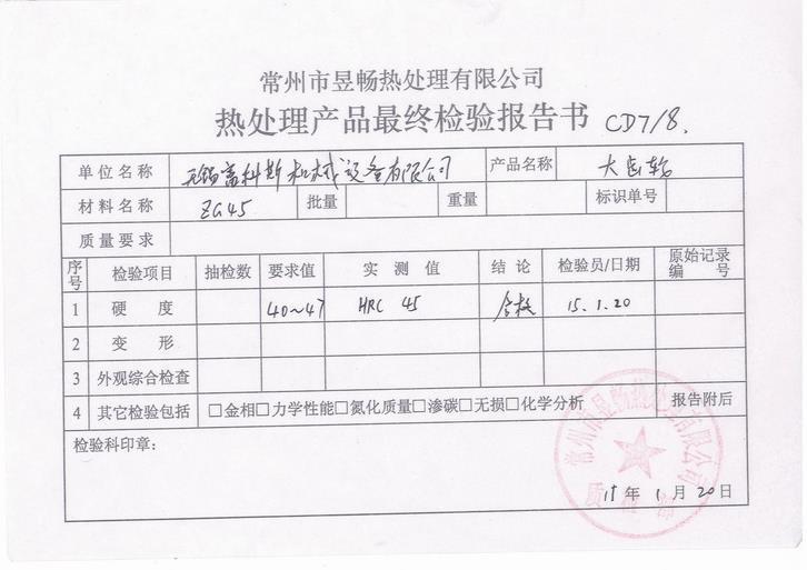
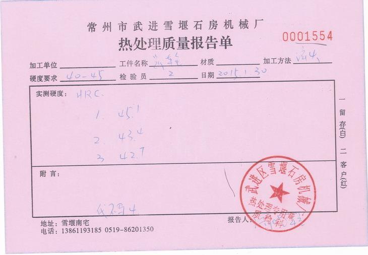
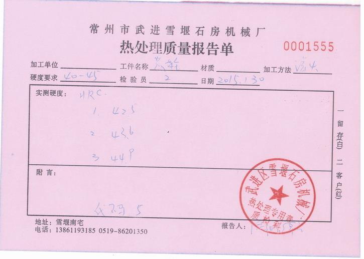
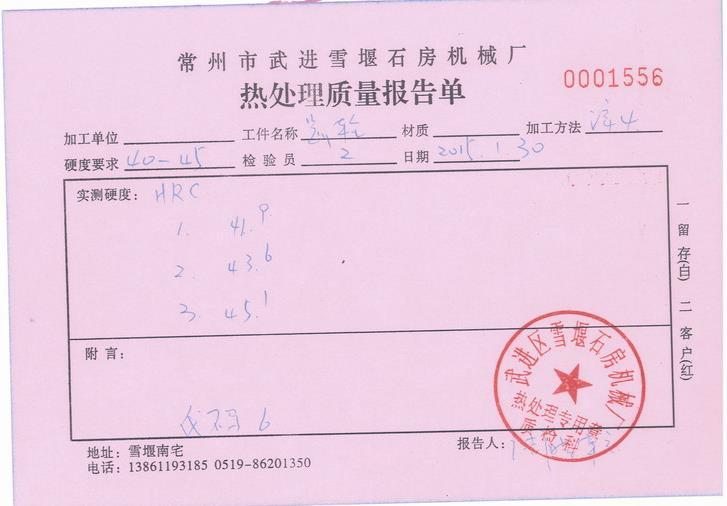
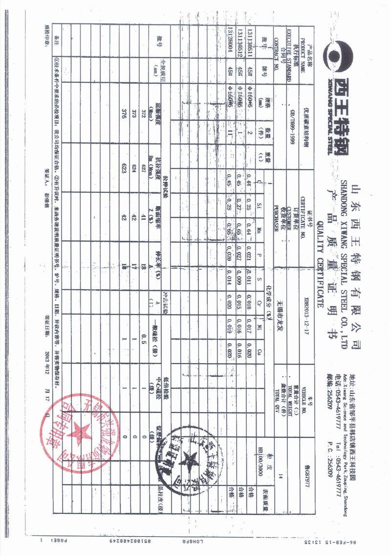
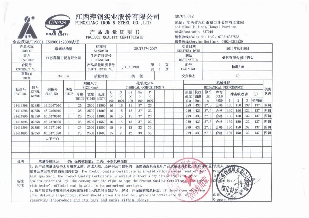
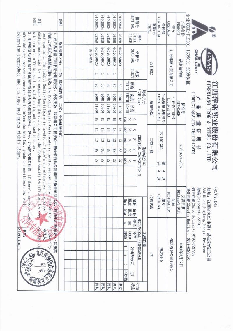
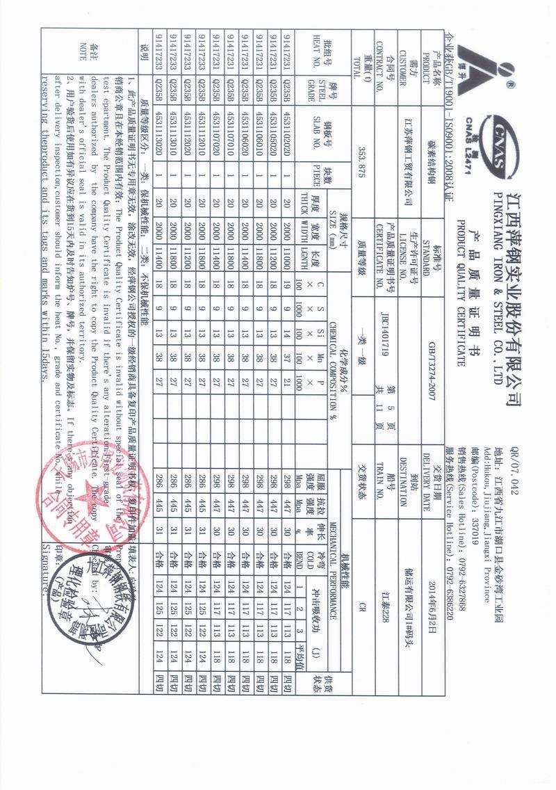
29 CWP 40 Part List Description IRIZAR HEAVY INDUSTRIES INC PART CODE QTY. DESCRIPTION MFG CODE TPQ ht MTR ht CWP40-M120 1 left table rotation gearbox CWP40-M121 1 left table rotation motor CWP40-M122 1 right table rotation gearbox CWP40-M123 1 right table rotation motor CWP40-M124 1 left tilt gearbox CWP40-M125 1 left tilt motor CWP40-M126 1 right tilt gearbox CWP40-M127 1 right tilt motor CWP40-M128 2 gear 1 on tilt reducer shaft (M124 & M126) C;150201D ; L4956 CWP40-M129 2 gear 2 on tilt shaft (M132) A;150122B CD7/8 CD7/8 CWP40-M130 2 gear 3 on tilt shaft (M132) E;150201F ; L4956 CWP40-M131 2 gear A;150201B ; L4956 CWP40-M132 2 tilt shaft C;150122D CWP40-M140 1 table rotation slewing bearing CWP40-M141 2 tilting slewing bearing CWP40-M142 2 bearing 1 on tilt shaft CWP40-M143 2 bearing 2 on tilt shaft CWP40 FRAME STRUCTURE MTR CERTIFICATE NO. JBC ; JBC ; JBC TPQ MFG ht tempering and quenching manufacture SN heat number Page # 29

30 CWP 40 Material Documentation IRIZAR HEAVY INDUSTRIES INC Page # 30

31 Page # 31
32 Page # 32
33 Page # 33
34 Page # 34


35 CWP 40 Electrical Part List IRIZAR HEAVY INDUSTRIES INC PART CODE CWP40-E100 CWP40-E101 CWP40-E102 CWP40-E103 CWP40-E104 CWP40-E105 CWP40-E106 CWP40-E107 CWP40-E108 CWP40-E109 CWP40-E110 CWP40-E111 CWP40-E112 CWP40-E113 CWP40-E114 CWP40-E115 CWP40-E116 CWP40-E117 CWP40-E118 CWP40-E119 CWP40-E120 DESCRIPTION N2 inverter control relay contactor control transformer resistance dc power fuse power lamp alarm lamp reset button e-stop button power contactor speed display control button resistance control transformer motor breaker PLC tilt limit switch Sw1 sensor magnetic contactor Page # 35
36 8.0 Limited Warranty IRIZAR HEAVY INDUSTRIES INC IRIZAR HEAVY INDUSTRIES INC warrants all new equipment to be free from defects in material and workmanship for the period of one year, provided that the equipment is installed and operated according to instructions. Any repairs or modification made by unauthorized third parties without written consent shall void this warranty. IRIZAR HEAVY INDUSTRIES INC's obligation under this warranty is expressly limited to replacing or repairing any defective part or correcting any manufacturing defect without charge during the warranty period, if IRIZAR s factory inspection confirms the existence of such defects. Exercise of IRIZAR s option of replacement or repair will be at IRIZAR s factory and/or warehouse; therefore no reimbursement for transportation cost of any kind will be allowed. IRIZAR HEAVY INDUSTRIES INC will not be liable for any loss or consequential damage or expense accruing directly or indirectly from the use of equipment covered by this limited warranty. Page # 36
WELDING POSITIONER OPERATION MANUAL MODEL TT-100 V1.0
 WELDING POSITIONER OPERATION MANUAL MODEL TT-100 Carefully read and understand these operation instructions before operating, inspecting, or servicing this product. This manual for use with Serial Numbers
TALCO FIRE SYSTEMS. LSF Start-Up Instructions. 1) IMPORTANT: Inspect the unit for damage. Report any damage to the freight carrier immediately.
 IMPORTANT: Inspect the unit for damage. Report any damage to the freight carrier immediately.") LSF Start-Up Instructions 1) IMPORTANT: Inspect the unit for damage. Report any damage to the freight carrier immediately. 2) PRE-START-UP: Be sure there is water in the pump. Bleed air at all high points
LSF Start-Up Instructions 1) IMPORTANT: Inspect the unit for damage. Report any damage to the freight carrier immediately. 2) PRE-START-UP: Be sure there is water in the pump. Bleed air at all high points
Operating Instructions and Parts Manual AHR-50 Auto Rewind Hose Reel
 Operating Instructions and Parts Manual AHR-50 Auto Rewind Hose Reel JET 427 New Sanford Road LaVergne, Tennessee 37086 Part No. M-426238 Ph.: 800-274-6848 Revision C 04/2017 www.jettools.com Copyright
CBC-300 Series & CBC-300C Series Dual Channel Adjust Clutch/Brake Controls
 CBC-300 Series & CBC-300C Series Dual Channel Adjust Clutch/Brake Controls P-269-89-0408 Installation Installation & Operating Instructions Contents Introduction........................... 2 Specifications.........................
model ps600 Address all communications and shipments to: FEDERAL SIGNAL CORPORATION
 MODEL: PS600 HZ: 60 A model ps600 installation and service manual for federal model ps600 FEDERAL SIGNAL CORPORATION POWER SUPPLY VOLTS: SERIES: 120VAC FEDERAL SIGNAL CORPORATION UNIVERSITY PARK, IL. U.S.A.
Positioning Solutions since Axis. Positioners
 Positioning Solutions since 1972 2-Axis Positioners 2-Axis Positioners Efficient and precise welding depends on the right positioning. PrestonEastin two-axis welding positioners are ideal for construction,
Positioning Solutions since Axis. Positioners
 Positioning Solutions since 1972 2-Axis Positioners 2-Axis Positioners Efficient and precise welding depends on the right positioning. PrestonEastin two-axis welding positioners are ideal for construction,
1-3 MANUAL STARTERS EXERCISE OBJECTIVE. Examine and describe the operation of manual motor starters. DISCUSSION
 1-3 MANUAL STARTERS EXERCISE OBJECTIVE Examine and describe the operation of manual motor starters. DISCUSSION Motor starters are made out of power switches and overload protection devices. They can be
Read this entire manual before operation begins.
 Read this entire manual before operation begins. Record below the following information which is located on the serial number data plate. Serial No. Model No. Date of Installation Contents Specifications.............
Pump Installation and Service Manual HRS Hydromatic Retractable System
 Pump Installation and Service Manual HRS Hydromatic Retractable System NOTE! To the installer: Please make sure you provide this manual to the owner of the pumping equipment or to the responsible party
4" ENVIRONMENTAL E-SERIES PUMPS OWNER'S MANUAL. DANGER warns about hazards that will cause. WARNING warns about hazards that can cause
 4" ENVIRONMENTAL E-SERIES PUMPS OWNER'S MANUAL BEFORE INSTALLING PUMP, BE SURE TO READ THIS OWNER S MANUAL CAREFULLY. CAUTION Fill pump with water before starting or pump will be damaged. The motor on
Innovatech User Manual. Predator 2400 T H E S U R F A C E P R E P A R A T I O N S P E C I A L I S T S
 Innovatech User Manual Predator 2400 T H E S U R F A C E P R E P A R A T I O N S P E C I A L I S T S CONTENTS Introduction... 3 Delivery... 3 Grinder Specifications... 4 Safety Warning... 4 Controls and
Embedded Rack Slide-out System
 Embedded Rack Slide-out System SERVICE MANUAL Rev: 02.16.2017 Page 1 Electric Embedded Rack Slide-out System TABLE OF CONTENTS Safety Information 3 Product Information 3 Operation 4 Extending Slide-Out
CAPACITOR ACTUATED PORTABLE STARTER CAPS USER GUIDE. INST048 Doc 3.01
 CAPACITOR ACTUATED PORTABLE STARTER CAPS USER GUIDE INST048 Doc 3.01 CONTENTS General Information...2 Charts...3 Before First Use...4 Safety Requirements...5 What to Expect from the CAPS...5 CAPS Diagram...6
FBD-NT Press Brake Installation Guide
 FBD-NT Press Brake Installation Guide Summary...2 Environmental conditions...2 Power supply...2 Machine installation...3 Location...4 Carrying...5 Using a crane...5 Using rollers...6 Foundation...7 Cleaning...7
ValveMate 7000 Controller Operating Manual
 A NORDSON COMPANY ValveMate 7000 Controller Operating Manual Steady Test Clear Time Set Fast Slow POWER RUN SETUP CYCLE A NORDSON COMPANY VALVEMATE 7000 Run Setup Purge Program Fast Slow Time Set Pressure
A39 UNIVERSAL SCR CHARGER
 A39 UNIVERSAL SCR CHARGER ECN/DATE CPN35971 21681 01/18 16816-6/05 15349-03 05/02 14575 02/01 14268 10/00 10400 9/96 106 BRADROCK DRIVE DES PLAINES, IL. 60018-1967 (847) 299-1188 FAX: (847) 299-3061 ISSUE
Grapple Kit Install & Grapple Bucket Manual
 Grapple Kit Install & Grapple Bucket Manual Model # Serial # Rev. 10/13 Rylind Manufacturing, Inc. 2801 Youngfield St Suite 250 Golden, CO 80401 Business/Sales Offices: 303-979-3548 Manufacturing Plant:
Instruction Manual PN-Z PACKED PLUNGER PUMP. This Manual should be made available to person responsible for installation, maintenance and operation.
 MILTON ROY INDIA (P) LTD Metering Pumps Instruction Manual PN-Z PACKED PLUNGER PUMP This Manual should be made available to person responsible for installation, maintenance and operation. PUMP MODEL: SERIAL
Models DP10 & DP20 Series Low Voltage Disconnects User s Manual Rev. 1.1 October 31, 2007
 B R A N D Models DP10 & DP20 Series Low Voltage Disconnects User s Manual Rev. 1.1 October 31, 2007 For Sales, Support and Service phone: 407-331-4793 fax: 407-331-4708 website: www.xenotronix.com email:
SB SWITCH CONTROL BOX
 Carson Manufacturing Co., Inc. 5451 North Rural Street Indianapolis, IN 462 Phone: (888) 577-6877 Fax: (317) 254-2667 www.carsonsirens.com SB-008-25 SWITCH CONTROL BOX INSTALLATION AND OPERATING INSTRUCTIONS
Top Brush Auto Retract (Zelio PLC)
") () Owner s Manual Sonny's Enterprises, Inc. 5605 Hiatus Road Tamarac, Florida 33321 16v1 *Table of Contents* Equipment Program - Manuals WARNING *SAFETY REQUIREMENTS* WARNING... 3 *INTRODUCTION*... 5 Product
() Owner s Manual Sonny's Enterprises, Inc. 5605 Hiatus Road Tamarac, Florida 33321 16v1 *Table of Contents* Equipment Program - Manuals WARNING *SAFETY REQUIREMENTS* WARNING... 3 *INTRODUCTION*... 5 Product
CBC-802 Plug-In Clutch/Brake Control with Solid State Switching
 DIST. AUTORIZADO Plug-In Clutch/Brake Control with Solid State Switching P-29-5 19-0409 Service & Installation Instructions An Altra Industrial Motion Company DIST. AUTORIZADO Brake (Red) and clutch (Green)
MODEL 5120 Tire Repair Station
 MODEL 5120 Tire Repair Station 00-0049 Installation, Operation & Repair Parts Information Branick Industries, Inc. 4245 Main Avenue P.O. Box 1937 Fargo, North Dakota 58103 REV01182017 P/N: 81-0058G CAUTION
RT404-FLEX II ROTARY TABLE OPERATING MANUAL
 P/N 561447 REV E AUG. 03 REV D NOV. 01 REV C APR. 01 REV B JULY 98 REV A AUG. 97 AUGUST 2003 RT404-FLEX II ROTARY TABLE OPERATING MANUAL 2003 I&J FISNAR INC. RT404-FLEX II ROTARY TABLE NOTE: Unlike the
MODEL L/R/EF Sectional Tire Spreader
 MODEL L/R/EF Sectional Tire Spreader Installation, Operation & Repair Parts Information Branick Industries, Inc. 4245 Main Avenue P.O. Box 1937 Fargo, North Dakota 58103 REV08032016 P/N: 81-0195E TABLE
TPHK Series Immersible Pump
 TPHK Series Immersible Pump Instruction Manual ISO 9001 Certified Walrus America Inc 234867 EC Declaration of Conformity Manufacturer: Walrus Pump Co., Ltd. Address: No. 83-14, Dapiantou, Sanjhih Township,
TPAK Series COOLANT PUMP
 TPAK Series COOLANT PUMP Instruction Manual ISO 9001 Certified WALRUS PUMP CO., LTD. EC Declaration of Conformity Manufacturer: Walrus Pump Co., Ltd. Address: No.83-14, Dapiantou, Sanzhi Dist., New Taipei
SSLS & SSLS4-27 Series Lift Tables
 Owner s Manual SSLS2.5-27 & SSLS4-27 Series Lift Tables Southworth Products Corp P.O. Box 1380, Portland, Maine 04104-1380 Phone: 800-743-1000 / 207-878-0700 Fax: 207-797-4734 www.southworthproducts.com
Operating Instructions Type MPT 53
 Operating Instructions www.turnstiles.us Type MPT 53 Contents 1. Delivery... 2 2. Safety...3-4 3 Description and operation... 5 4. Technical Data 6 5. oundation...6-9 6. Assembly and installation...10-13
Setup and Configuration Guide Universal Switch Interface
 Table of Contents J1939 inmotion Cell Setup and Configuration Guide Universal Switch Interface Overview... 2 Warnings... 3 J1939 inmotion Cell Technical Details... 4 inmotion Cell Installation Steps...
POWER PINNER RAPID FIRE 7005 RF OPERATOR S MANUAL
 POWER PINNER RAPID FIRE 7005 RF OPERATOR S MANUAL Copyright: February 20, 2007 Revised: 12-11-2015. Gripnail Corporation An Employee Owned Company 97 Dexter Road East Providence, Rhode Island 02914-2045
Linear Actuator Swing Gate Operator Installation Manual Model # LA405-24
 Linear Actuator Swing Gate Operator Installation Manual Model # LA405-24 2 Contents Contents Product Information and Specs. 3 Mechanical 3 Electrical, Line Connections 3 Electrical, Control Connections
Read this entire manual before operation begins.
 Read this entire manual before operation begins. Record below the following information which is located on the serial number data plate. Serial No. Model No. Date of Installation Contents Specifications.............
Troubleshooting Bosch Proportional Valves
 Troubleshooting Bosch Proportional Valves An Informative Webinar Developed by GPM Hydraulic Consulting, Inc. Instructed By Copyright, 2009 GPM Hydraulic Consulting, Inc. TABLE OF CONTENTS Bosch Valves
FHC-1D user manual. Features
 Phason The Fan and Heater Control (FHC-1D) automatically controls the temperature in a room by adjusting the speed of variable speed fans and controlling a heater interlock. When the temperature is at
Operator s Manual. Fairbanks FH Series by Fairbanks Scales, Inc. All rights reserved. . Revision 1 06/2017
 Operator s Manual Fairbanks FH Series 2017 by Fairbanks Scales, Inc. All rights reserved 51393. Revision 1 06/2017 Amendment Record Fairbanks FH Series Operator s Manual Operator s Manual Document 51393
Dor-O-Matic. Series Slide Control. Installation Instructions
 Dor-O-Matic Series 96000 Slide Control Installation Instructions DOR - O MATIC 7350 W. Wilson Ave. Harwood Heights, IL 60706 Toll Free: 1-800-543-4635 In Illinois: 708-867-7400 Sales FAX: 708-867-0291
All products subject to this warranty must be returned for examination, repair or replacement to:
 Limited Warranty The software and sensors are warranted by the manufacturer, Toledo Integrated Systems, to be free from defects in workmanship for one year from the date of manufacturer s shipment. This
FTFR Maintenance and Parts Manual SQ-1 FLOOR TRUSS FINISH ROLLER. Operators Manual
 FTFR Maintenance and Parts Manual SQ-1 FLOOR TRUSS FINISH ROLLER Operators Manual FOREWORD This manual explains the proper maintenance of Square 1 Design Floor Truss Finish Roller as well as the daily
Premium Supply. Tilt Deck. Models PCK-TD PCK-PTD. Operator s Manual and Installation Instructions
 Tilt Deck Models PCK-TD PCK-PTD Operator s Manual and Installation Instructions Premium Supply 2038 West Interstate 30 866-934-0777 Proud members of: and June 1, 2015 Table of Contents Introduction...
FEATURES. Power Status and Charge Indicator: A red LED indicates the battery is charging and a green LED indicates the battery is fully charged.
 7-in-1 Power Station Model: 52036 DO NOT RETURN TO STORE. Please CALL 800-348-5004 for parts and service. CALIFORNIA PROPOSITION 65 WARNING: You can create dust when you cut, sand, drill or grind materials
"WHERE TUBING AND FITTINGS COME TOGETHER"
 CLEAN ROOM DEVICES, LLC "WHERE TUBING AND FITTINGS COME TOGETHER" CRD200SS TUBE EXPANDER OPERATIONS MANUAL VERSION 4.3 LAST EDITED 06.17.15 cleanroomdevices.com Table of Contents Table of Contents....1
Service/Installation Manual Full Wall Slide Systems CONTENTS. 82-S0379 Rev 3. Page. Before you operate the slide system 2
 Service/Installation Manual Full Wall Slide Systems CONTENTS Page Before you operate the slide system Operating instructions Preventive maintenance Manually overriding your slide system 0" Stroke system
Part# W HID Flood Light Kit
 400 W. Artesia Blvd. Compton, CA 90220 Fax: (310) 747-3912 Ph: 1-800-776-0767 E-Mail: info@procompusa.com Website: www.procompusa.com Revised PRO COMP SUSPENSION Part# 9640 4 35W HID Flood Light Kit 9670
1250 LB. CAPACITY MECHANICAL WHEEL DOLLY
 1250 LB. CAPACITY MECHANICAL WHEEL DOLLY 67287 SET-UP AND OPERATING INSTRUCTIONS Visit our website at: http://www.harborfreight.com Read this material before using this product. Failure to do so can result
MODEL TC400 TIRE CART. Installation, Operation & Repair Parts Information REV P/N:
 MODEL TC400 TIRE CART Installation, Operation & Repair Parts Information REV061614 P/N: 81-0245 1 TABLE OF CONTENTS SAFETY INSTRUCTIONS 2 DEFINITIONS 2 SPECIFICATIONS 3 INSTALLATION INSTRUCTIONS 3 OPERATING
Wedge-loc Coupler Installation Manual Pin-loc Coupler Installation Manual
 Wedge-loc Coupler Installation Manual Pin-loc Coupler Installation Manual Coupler Models SLH1042W, SLH10M, SLH1022H LH2042W, LH3042W, LH4042W, LH5062W, LH6062W LH20M, LH30M, LH40M LH2022H, LH3022H, LH4022H,
Adjustable Angled Incline Conveyor Owners Manual with Operating Instructions
 Adjustable Angled Incline Conveyor Owners Manual with Operating Instructions Revision 012211 Table of Contents Basic Conveyor Features 3 Getting Started 4 Setting Up the Incline Conveyor 5 Belt Removal
J1 Plug Pin Identification
 D D8 D D D D ART_8 J 8 D D0 R R R R TB 80 D D D D D D J Plug Pin Identification PIN # WIRE # SIGNAL FUNCTION 0 INPUT Drive Reverse INPUT Drive Forward OUTPUT Brake, Decel Valve signal 8 INPUT Steer Left
Level-Up Motorhome Leveling
 Level-Up Motorhome Leveling Rev: 08.06.18 Page 1 CCD-0001751 TABLE OF CONTENTS Introduction 3 Components 3 Operation 5 Selecting a Site 5 Automatic Leveling Procedure 5 Automatic Leveling Descriptive Logic
CLEAN ROOM DEVICES, LLC "WHERE TUBING AND FITTINGS COME TOGETHER"
 CLEAN ROOM DEVICES, LLC "WHERE TUBING AND FITTINGS COME TOGETHER" CRD400 Fitting Inserter OPERATIONS MANUAL VERSION 3.1 LAST EDITED 03.08.11 DOCUMENT NUMBER 001 cleanroomdevices.com 1 Table of Contents
40041 Heavy Duty ADA System with Booster Bracket for JK Heavy Duty ADA System with Booster Bracket for 2012 to Current JK
 40041 Heavy Duty ADA System with Booster Bracket for 2007-2011 JK 40044 Heavy Duty ADA System with Booster Bracket for 2012 to Current JK 40049 Heavy Duty ADA System Universal for all vehicles (booster
TPHK Series Immersible Pump
 TPHK Series Immersible Pump Instruction Manual ISO 9001 Certified WALRUS PUMP CO., LTD. EC Declaration of Conformity Manufacturer: Walrus Pump Co., Ltd. Address: No.83-14, Dapiantou, Sanzhi Dist., New
LIGHTSTICK / LIGHTSTICK PLUS Germicidal Ultraviolet Light
 LIGHTSTICK / LIGHTSTICK PLUS Germicidal Ultraviolet Light Installation & Operation Manual This manual covers the following models: LightStick #19300 LightStick Plus #19301 GENERAL This product emits germicidal
Service Manual Model L1000 Smart Lift
 Service Manual Model L1000 Smart Lift Form #1-147 Rev. 10/1/13 Table of Contents Parts Breakdown 3 Monthly Maintenance Checklist 5 Smart Lift Operating Instructions 7 Scale Calibration 8 Advanced Smart
Premium Supply. Tilt Deck. Models PCK-TD PCK-PTD CTD-310-K. Operator s Manual and Installation Instructions
 Tilt Deck Models PCK-TD PCK-PTD CTD-310-K Operator s Manual and Installation Instructions Premium Supply 2038 West Interstate 30 866-934-0777 Proud members of: and April 20, 2018 Table of Contents Introduction...
GRUNDFOS INSTRUCTIONS MTC. Installation and operating instructions
 GRUNDFOS INSTRUCTIONS MTC Installation and operating instructions LIMITED WARRANTY Products manufactured by GRUNDFOS PUMPS CORPORATION (Grundfos) are warranted to the original user only to be free of defects
BUG PREP KIT 2.0 HAND-PREP SYSTEM. User Manual REV A reva0616
 BUG PREP KIT 2.0 HAND-PREP SYSTEM User Manual REV A 4000110 reva0616 Hydra-Flex, Hydra-Flex, Inc. 2016 Inc. 2016 Page 1 TABLE OF CONTENTS Overview 3 Standard Bug Prep Kit 2.0 3 Bug Prep Retro Controller
SSR SSR SSR SSR
 DMX 52 Page DMX52 decoder firing board module 20 VAC reference Input 2 3 4 The Thyristor Firing board is compatible withdmx52 control standard 4 DMX52 triggers 2 3 4 - +- +- +- + The can trigger control
CLEAN ROOM DEVICES, LLC "WHERE TUBING AND FITTINGS COME TOGETHER"
 CLEAN ROOM DEVICES, LLC "WHERE TUBING AND FITTINGS COME TOGETHER" CRD600AF Automatic Fitting Inserter With Auto Feed OPERATIONS MANUAL (Shown with optional alcohol dispenser) 1 VERSION 1.1 LAST EDITED
Installation & Operators Manual
 Installation & Operators Manual Model Serial Number Purchase Date 2007-2008 SegVator, LLC Patent Pending All Rights Reserved Important Safety Information Make sure the vehicle has a properly installed
The function of this Dynamic Active Probe has divided into three preferences on the screen main Menus:
 1.0 Introduction: This probe is designed to provide an additional help to automotive technicians in trouble shooting of electrical circuits problems in the car. Apart from using the normal multi tester,
ROCKLEA TRUCK ELECTRICAL. Sleeper Air NXT. Owner s Manual. Revision th March 2013
 ROCKLEA TRUCK ELECTRICAL Sleeper Air NT Owner s Manual Revision 230 24 th March 2013 Rocklea Truck Electrical Rocklea Truck Electrical is Brisbane's premier truck lighting and custom accessory manufacturer
1500 Series Roll Off Hoist. Owner s Manual (5-06)
") 1500 Series Roll Off Hoist Owner s Manual (5-06) Section 1: General Information Introduction Safety Information Warranty Information Table of Contents Section 2: Operation Operating the P.T.O. Operating
1500 Series Roll Off Hoist Owner s Manual (5-06) Section 1: General Information Introduction Safety Information Warranty Information Table of Contents Section 2: Operation Operating the P.T.O. Operating
CBC-802 Plug-In Clutch/Brake Control with Solid State Switching
 CBC-02 Plug-In Clutch/Brake Control with Solid State Switching P-2104-WE 19-054 Service & Installation Instructions An Altra Industrial Motion Company Brake (Red) and clutch (Green) indicator lights When
OWNER S GUIDE 8A DURALIFT II 13,200 LB. CAPACITY. Link Mfg. Ltd th St. N.E. Sioux Center, IA USA
 OWNER S GUIDE 8A000715 DURALIFT II 13,200 LB. CAPACITY Link Mfg. Ltd. 223 15th St. N.E. Sioux Center, IA USA 51250-2120 www.linkmfg.com QUESTIONS? CALL CUSTOMER SERVICE 1-800-222-6283 DEALER / INSTALLER:
Instructions 3A4793B EN. See page 3 for a complete list of model descriptions and part numbers.
 Instructions Variable Frequency Drives 3A4793B EN Variable frequency drives (VFDs) to power and control electric motor driven agitators. For professional use only. Not approved for use in explosive atmospheres
Hydraulic Transmission Jacks
 Hydraulic Transmission Jacks Operating Instructions & Parts Manual Model Number Atd-7435 Atd-7436 Atd-7437 Capacity 1100 Lb. 2000 Lb. 3000 Lb. Model Atd-7435 Model Atd-7436 Model Atd-7437 Atd Tools Inc.
Dor-O-Matic. Series Slide Control. Installation Instructions
 Dor-O-Matic Series 96000 Slide Control Installation Instructions DOR - O MATIC 7350 W. Wilson Ave. Harwood Heights, IL 60706 Toll Free: 1-800-543-4635 In Illinois: 708-867-7400 Sales FAX: 708-867-0291
SUBMERSIBLE MINI-PUMP
 SUBMERSIBLE MINI-PUMP Model 41287 Set up And Operating Instructions Diagrams within this manual may not be drawn proportionally. Due to continuing improvements, actual product may differ slightly from
INSTALLATION INSTRUCTIONS
 Safety Notices... 1... 3 Specifications... 3 General... 3 Electrical... 3 Hydraulic Connections... 3 Components... 4 Assembly... 4 Implement Installation... 7 Hydraulic Connections... 9 Closed-Center Hydraulics...
BMRX Series ROTARY LEVEL CONTROL
 BMRX Series ROTARY LEVEL CONTROL OPERATING INSTRUCTIONS PLEASE READ CAREFULLY 925-0292 Rev C TABLE OF CONTENTS GENERAL SPECIFICATIONS... 3 SAFETY SUMMARY... 4 1.0 INTRODUCTION... 5 2.0 INSTALLATION...
Updated: October 2012
 T: (630) 794-5100 EMERGENCY POWER FUEL SYSTEMS Earthsafe Systems, Inc. 7320 S. Madison Willowbrook, IL 60527 F: (630) 794-5106 info@earthsafe.com www.earthsafe.com Updated: October 2012 The information
Service Manual. Model L500 and L600 Smart Lift. WARNING: Cancer and Reproductive Harm - Form #1-144 Rev.
 Service Manual Model L500 and L600 Smart Lift WARNING: Cancer and Reproductive Harm - www.p65warnings.ca.gov. Form #1-144 Rev. 2/5/19 Table of Contents Parts Breakdown 3 Monthly Maintenance Checklist 5
Operating Instructions and Parts Manual SLT-330F Scissor Lift Table
 Operating Instructions and Parts Manual SLT-330F Scissor Lift Table For serial no. 17020001 and higher JET 427 New Sanford Road LaVergne, Tennessee 37086 Part No. M-140771 Ph.: 800-274-6848 Revision C
A48 / A48B (base plate) BATTERY CHARGER
 BATTERY CHARGER") A48 / A48B (base plate) BATTERY CHARGER CPN41054 ISSUE DATE: 12315-8/98 ECN/DATE 106 BRADROCK DRIVE DES PLAINES, IL. 60018-1967 (847) 299-1188 FAX: (847)299-3061 15349-07-07/02 16041 6/03 14575-2/01 INSTRUCTION
A48 / A48B (base plate) BATTERY CHARGER CPN41054 ISSUE DATE: 12315-8/98 ECN/DATE 106 BRADROCK DRIVE DES PLAINES, IL. 60018-1967 (847) 299-1188 FAX: (847)299-3061 15349-07-07/02 16041 6/03 14575-2/01 INSTRUCTION
Innovatech User Manual. Predator 3200 T H E S U R F A C E P R E P A R A T I O N S P E C I A L I S T S
 Innovatech User Manual Predator 3200 T H E S U R F A C E P R E P A R A T I O N S P E C I A L I S T S CONTENTS Introduction... 3 Delivery... 3 Grinder Specifications... 4 Safety Warning... 4 Controls and
Operators Manual ECO-AIR-IVS Internal Valve Actuation System
 2534-A Shell Road Georgetown, TX 78628 www.parafour.com 512-626-4099 Operators Manual ECO-AIR-IVS Internal Valve Actuation System Ver 1.0 Warnings:!! This device is electrically operated and should only
Infinitybox Express Road Race Car Kit Installation Guide
 Table of Contents Infinitybox Express Road Race Car Kit Installation Guide Overview... 2 Warnings... 3 J1939 POWERCELL Technical Details... 4 IOX Input/Output Module Technical Details... 4 Kit Contents...
Deere G & GP Series Snow Wing Installation
 Deere G & GP Series Snow Wing Installation Model: Serial Number: Rev. 10/13 Rylind Manufacturing, Inc. 2801 Youngfield St Suite 250 Golden, CO 80401 Offices: 303-979-3548 Fax: 303-979-4730 www.rylind.com
INSTALLER MANUAL USER MANUAL. Contents
 Installation & user manual two way Contents INSTALLER MANUAL Important information General 1. Technical data 2. Description Installation: 1. Positioning the unit 2. Connection. 3. Parts description. 4.
SPC-PANEL Simplex, Single Phase Pump Control Panel
 Pump Installation and Service Manual SPC-PANEL Simplex, Single Phase Pump Control Panel Pump Controls for 2 HP Grinder Pumps NOTE! To the installer: Please make sure you provide this manual to the owner
Tekleen GB6 & GB7 USERS AUTOMATIC FILTERS, INC. MANUAL
 AUTOMATIC FILTERS, INC. 67 S. LA CIENEGA BLVD. LOS ANGELES, CA 90034 30 839 88 800 336 94 FAX 30 839 6878 www.tekleen.com info@tekleen.com Tekleen GB6 & GB7 USERS MANUAL GB6 & GB7 USERS MANUAL AUTOMATIC
BOLT-ON AND WELD-ON FLUSH FLOOR SLIDEOUT SYSTEMS OPERATION AND SERVICE MANUAL
 BOLT-ON AND WELD-ON FLUSH FLOOR SLIDEOUT SYSTEMS OPERATION AND SERVICE MANUAL TABLE OF CONTENTS SYSTEM...... Warning........ Description...... Prior to Operation OPERATION... Main Components... Mechanical...
CBC-300 & CBC Series Dual Channel Adjust Clutch/Brake Controls
 CBC-300 & CBC-300- Series Dual Channel Adjust Clutch/Brake Controls P-205-WE 89-0549 Installation & Operating Instructions An Altra Industrial Motion Company Contents Introduction... 2 Specifications...
24 Linear Actuator 115 Volts A.C. (Cat. # C430A)
") Installation, Operation & Parts Manual Read carefully the information provided. Retain manual for future reference. 24 Linear Actuator 115 Volts A.C. (Cat. # C430A) Page 1 of 8 IS10007.doc 11/15/06 IMPORTANT!
Installation, Operation & Parts Manual Read carefully the information provided. Retain manual for future reference. 24 Linear Actuator 115 Volts A.C. (Cat. # C430A) Page 1 of 8 IS10007.doc 11/15/06 IMPORTANT!
PD404-AN V analog control 4 Channel x 500 W Dimmer & Switch Packs ANALOG 0-10 V. Serial Number
 0-10V analog control 4 Channel x 500 W Dimmer & Switch Packs ANALOG 0-10 V 4 circuit Analog 1-10V 4 x 4 A. Dimmer pack Serial Number Dimmers Indicators Digital Lighting Systems,Inc Info@digitallighting.com
SHOCK RELAY R INSTRUCTION MANUAL WARNING
 EHFSB006000A0 SHOCK RELAY R TSBSB Series INSTRUCTION MANUAL! WARNING Make sure you read this instruction manual thoroughly before installing, wiring, operating and inspecting this SHOCK RELAY Please make
Air Compressor. Owner s Manual. Sonny's Enterprises, Inc Hiatus Road Tamarac, Florida v1
 Owner s Manual Sonny's Enterprises, Inc. 5605 Hiatus Road Tamarac, Florida 33321 16v1 *Table of Contents* WARNING *SAFETY REQUIREMENTS* WARNING... 3 *INTRODUCTION*... 5 Product Specifications... 6 Optional
OPERATING INSTRUCTIONS PLEASE READ CAREFULLY
 OPERATING INSTRUCTIONS PLEASE READ CAREFULLY 925-0330 Rev 0 0416 TABLE OF CONTENTS SAFETY SUMMARY... 3 SPECIFICATIONS... 4 1.0 INTRODUCTION/DESCRIPTION.... 5 2.0 LOCATION AND MOUNTING... 5 3.0 CONNECTIONS
Induction Power Supplies
 Induction Power Supplies 7.5kW; 135 400kHz 480V version (Integral Heat Station) User s Guide Model 7.5-135/400-3-480 SMD Control Brds Rev. D 5/08 Table of Contents 1. Specifications and features...3 2.
On-A-Roll Lifter Instruction Manual for Standard Models Read Before Use!
 On-A-Roll Lifter Instruction Manual for Standard Models Read Before Use! Important instructional, safety and precautionary information! It is the user s responsibility to exercise good judgment, common
Crary Tile Pro: Stringer Trailer Owners Manual
 Crary Tile Pro: Stringer Trailer Owners Manual Crary Agricultural Solutions, LLC October 2013 Tile Pro Crary Agricultural Solutions, LLC P.O. Box 237 Morgan, MN 56266 507-249-3176 507-249-3146 FAX Website:
TD77-2 and ULB42-TD-2 TRAFFIC DIRECTOR CONTROL BOXES
 TD77-2 and ULB42-TD-2 TRAFFIC DIRECTOR CONTROL BOXES Important: This product is used to direct traffic. Improper use may result in vehicular collision, personal injury and/or death. Star Headlight & Lantern
HF4145 FOLDING MULTI-POSITION WORKOUT BENCH
 HF4145 FOLDING MULTI-POSITION WORKOUT BENCH Note: Both Serial Number and Model Number are Required when Ordering Parts RECORD SERIAL NUMBER HERE CATALOG NUMBER 0406-001 Customer Service (800) 548-5438
MPT-250B SPECIFICATIONS AND OPERATING INSTRUCTIONS
 1. SAFETY The MPT-250B Wire Crimp Pull Tester is a force measurement device, and as such should be operated with due caution. Operators should wear safety glasses for eye protection because the crimp under
HIGH DUMP ROLL-OUT BUCKET
 HIGH DUMP ROLL-OUT BUCKET Model # Serial # Rev. 01/14 Rylind Manufacturing, Inc. 2801 Youngfield St Suite 250 Golden, CO 80401 Business/Sales Offices: 303-979-3548 Manufacturing Plant: 970-522-2859 www.rylind.com
SDS Enclosed Star-Delta Starter User Guide
 SDS Enclosed Star-Delta Starter User Guide (7.5kW~90kW) V2.0.0 PLEASE NOTE: AS STANDARD AND UNLESS OTHERWISE SPECIFIED, THIS PRODUCT IS EQUIPPED WITH A BASIC LOW INTEGRITY EMERGENCY STOP CIRCUIT STOPPING
Read this entire manual before operation begins.
 Read this entire manual before operation begins. Record below the following information which is located on the serial number data plate. Serial No. Model No. Date of Installation Contents Specifications.............