TELETOM PREINSTALLATION MANUAL
|
|
|
- Sheena Ward
- 5 years ago
- Views:
Transcription

1 TELETOM PREINSTALLATION MANUAL
2 MANUAL ORGANIZATION SAFETY CONTENTS SECTION 1 INTRODUCTION DESCRIPTION PRE-INSTALLATION RESPONSIBILITIES BERCHTOLD RESPONSIBILITIES OWNER RESPONSIBILITIES STIFFNESS SUPERSTRUCTURE DESIGN AND CONSTRUCTION RECOMMENDATIONS WIRING MEDICAL (AND OTHER) GASES OPTIONAL TELEVAC SMOKE EVACUATION SYSTEM TESTING STORAGE AND HANDLING PRE-INSTALLATION COMPONENTS TELETOM EQUIPMENT MANAGEMENT SYSTEM COMPONENTS SECTION 2 PRE-INSTALLATION STRUCTURAL REQUIREMENTS INTRODUCTION GENERAL SUPERSTRUCTURE DESIGN AND CONSTRUCTION RECOMMENDATIONS GENERAL NOTES ON SUPERSTRUCTURE DESIGN SINGLE MOUNT EQUIPMENT MANAGEMENT SYSTEMS IDENTIFICATION SUPERSTRUCTURE DESIGN LOADS TYPICAL DESIGN AND CONSTRUCTION FOR TELETOM SINGLE MOUNT SUPERSTRUCTURE MOUNTING MATERIALS AND DETAILS CEILING OPENING AND SOFFIT ENVELOPE TANDEM MOUNT EQUIPMENT MANAGEMENT SYSTEMS IDENTIFICATION SUPERSTRUCTURE DESIGN LOADS TYPICAL TANDEM MOUNT SUPERSTRUCTURE DESIGN AND CONSTRUCTION MOUNTING MATERIALS AND DETAILS CEILING OPENING AND SOFFIT ENVELOPE SECTION 3 PRE-INSTALLATION WIRING REQUIREMENTS BERCHTOLD SUPPLIED ELECTRICAL COMPONENTS (STANDARD) ELECTRICAL JUNCTION BOX ELECTRICAL POWER OUTLETS ADDITIONAL ELECTRICAL POWER SUPPLIES OWNER PRE-INSTALLATION WIRING REQUIREMENTS (STANDARD) WIRING RUNS ELECTRICAL JUNCTION BOX INSTALLATION WIRING CONNECTIONS HIGH VOLTAGE CONDUIT LOW VOLTAGE ELECTRICAL REQUIREMENTS COMBINATION BOOM & LIGHT / FLAT PANEL 3-6 iv TELETOM Pre-Installation Guide
3 MANUAL ORGANIZATION SAFETY SECTION 4 PRE-INSTALLATION REQUIREMENTS FOR MEDICAL GASES BERCHTOLD SUPPLIED MEDICAL GAS RISER PNEUMATIC BRAKE GAS SPECIFICATIONS OWNER PRE-INSTALLATION MEDICAL GAS RISER REQUIREMENTS MEDICAL GAS PIPING MEDICAL GAS RISER INSTALLATION SECTION TELEVAC SMOKE EVACUATION SYSTEM BERCHTOLD SUPPLIED TELEVAC MOTOR OWNER PRE-INSTALLATION TELEVAC PRE-INSTALLATION REQUIREMENTS TELEVAC VACUUM MOTOR INSTALLATION VIDEO EQUIPMENT OWNER PRE-INSTALLATION VIDEO REQUIREMENTS TELETOM Pre-Installation Guide v

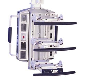
4 MANUAL ORGANIZATION SAFETY 400/600 Series Anesthesia Boom viii TELETOM Pre-Installation Guide
5 e. Test equipment is to be calibrated by an approved testing laboratory in accordance with standard recognized procedures. SINGLE MOUNT EQUIPMENT MANAGEMENT SYSTEMS (TS) CAUTION The owner or the owner s contractor has the final responsibility for the strength and rigidity of the superstructure. BERCHTOLD Corporation does not warrant or certify superstructure designs. An inadequate superstructure will affect the ability of the TELETOM unit to perform in the manner intended. An inadequate superstructure design can also result in damage to the equipment. Equipment warranty service charges related to an inadequate superstructure design or installation are at the customer s expense. Refer to Owner Responsibilities on page 1-3 for a description of the owner s design and construction responsibilities. Identification TELETOM single mount units are identified by a 500-series or 700-series model number and a TS prefix. TELETOM units with integrated light(s) or monitor arms have a TC prefix. The 500 Series units have zero, one, or two fixed arms. The 700 Series models have either one articulating arm or one fixed arm above one articulating arm Superstructure Design Loads Table 2-1 shows the weight and moment for TELETOM single mount Equipment Management Systems. The data shown are for the heaviest unit and the highest rotational moment. Designing for the heaviest model with the highest torque will provide adequate support for the heaviest unit, but will not significantly add to the cost of the installation of the lightest unit. This design margin also increases flexibility for future product upgrades. The installed weights and moments shown in Table 2-1 include both the weight of the TELETOM components and the maximum equipment load. Table 2-1. Single Mount TELETOM Weights and Moments Static Standard Weight Moment Lb (Kg) Ft Lb (N M) 801 (363) 4071 (5520) The superstructure must be strong enough to support the weight and rigid enough to constrain rotation to less than 0.1 at the mounting plate. TELETOM Pre-Installation Guide 2-3
6 Typical Design and Construction for TELETOM Single Mount Superstructure FIGURE 2-1 shows the design and the construction materials recommended for a successful TELETOM Equipment Management System single mount Installation. Other constructions are possible. However, the use of other designs and construction materials should be considered only after consultation with a structural engineer. Structural Concrete Slab Normal Weight ƒ c = 3000PSI (20684 kpa) TELEVAC Smoke Evacuation System (See Section 5) TYP ¼ 6mm See Figure /16 (310mm) 2 (51mm) F See Figure 2-4 TELEVAC Hose to TELETOM Max. Length 10 (3m) TYP ¼ 6mm 5 (127mm) ₁₆ (8mm) ₁₆ (8mm) 16 (406mm) Soffit Envelope (Figure 2-6) ~23.25 Square X ~6 Deep (590mm Square X 150mm Deep) E Finished Ceiling D 45º Min. 60º Max. 60 (1.5mm) Maximum C See Figure 2-5 for Ceiling Opening Clearance for Electrical and Medical Gas Options (8mm) ₁₆ (TYP Top & Bottom) See Figure 2-3 B 5 (127mm) Minimum Edge Distance A 5-½ (140mm) Minimum 2 (51mm) 2 (51mm) 8 (203mm) 2 (51mm) FIGURE 2-1 Recommended TELETOM Single Mount Superstructure Design and Construction Materials 2-4 TELETOM Pre-Installation Guide
7 FIGURE 2-2 shows the design and the construction materials recommended for a successful installation of a TELETOM Equipment Management System with lights and monitor arms installed. Other constructions are possible. However, the use of other designs and construction materials should be considered only after consultation with a structural engineer. 5-½ (140mm) Minimum 60 (1.5mm) Maximum Structural Concrete Slab Normal Weight ƒ c = 3000PSI (20684 kpa) TELEVAC Smoke Evacuation System (See Section 5) TYP ¼ 6mm See Figure /16 (310mm) 2 (51mm) F See Figure 2-4 TELEVAC Hose to TELETOM Max. Length 10 (3m) ¼ 6mm TYP 5 (127mm) ₁₆ (8mm) ₁₆ (8mm) 16 (406mm) 2 (51mm) B 2 (51mm) A 5 (127mm) Minimum Edge Distance ₁₆ (8mm) (TYP Top & Bottom) See Figure 2-3 C See Figure 2-5 for Ceiling Opening Clearance for Electrical and Medical Gas Options D 45º Min. 60º Max. E Soffit Envelope (Figure 2-6) ~23 Square X ~6 Deep (584mm Square X 150mm Deep) Finished Ceiling 2 ½ (64mm) 8 (203mm) 2 (51mm) FIGURE 2-2 Recommended Super Structure Design and Construction Materials for TELETOM Units with Light(s) or Monitor Arm(s) TELETOM Pre-Installation Guide 2-5
8 Mounting Materials and Details The following information describes the materials used and provides important details on installation techniques and processes. See General Notes on Superstructure Design on page 2-2 for materials specifications and testing recommendations. A. L-angle Superstructure Brackets (4 required) 4 x 4 x 3/8 X 12 (102mm x 102mm x 10mm x 305mm) long with two Ø1/2 x 4 (Ø13mm x 102mm) embedded expansion anchors Leave 5 (127mm) from the center of each mounting bolt clear for wrenching. B. Standard pipe Ø6 (Ø152mm) 1. The pipe must be welded to the BERCHTOLD supplied TELETOM mounting plate (C) and to the owner supplied superstructure mounting plate (F). Do not attach supplemental supports to the pipe. The supports will not constrain the rotational forces when attached to the pipe. This could lead to a failure of the Equipment Management System to operate as intended. Drifting of the Equipment Management System could result in injury to personnel. 2. Do not attach any supplemental supports to the pipe. The supports will not constrain the rotational force when attached to the pipe. Refer to FIGURE 2-3 for important details on the support of the TELETOM mounting plate. C. TELETOM Mounting Plate (Supplied by BERCHTOLD, and installed by the owner or the owner s contractor) 1 x 15 x 15 (25mm x 381mm x 381mm) with six Ø7/8 (Ø22mm) threaded rods spaced in a 10 (252mm) bolt circle D. L-angle Support Braces (4 required) 3 x 3 x 1/4 (76mm x 76mm x 6mm) 1. BERCHTOLD recommends that the L-angle support braces be welded to both the superstructure brackets (A-FIGURE 2-1 or FIGURE 2-2) and to the TELETOM mounting plate (C). 2. Support braces (D) must be welded to the TELETOM mounting plate (C). 3. Support braces or kickers must be attached only at the corners, and they must be at 90 angles to one another (see FIGURE 2-3). 2-6 TELETOM Pre-Installation Guide
9 Legend: A= 15 (381mm) B= 12.2 (310mm) C= 8.27 (210mm) D= 1.37 (35mm) E= 3.37 (85.7mm) F= 3.48 (88.5mm) G= 0.75 (19mm) H= 8.58 (218mm) J= 8 (204mm) K= 6.77 Ø (172mm Ø) L= 60 M= 6.5 (165mm) N= 0.5 (12.7mm) P= 10 Ø (252mm Ø) B.C. R=.906 Ø (23mm Ø) S=.875 Ø (22.2mm Ø) Threaded Rod 1/4 (6mm) No No FIGURE 2-3 TELETOM Mounting Plate and Support Attachments 4. The installed TELETOM mounting plate must be level to within /16 (310mm) E. The bottom of the TELETOM mounting plate (C) must be installed as shown in FIGURE 2-1 or FIGURE 2-2 For typical single mount installations as shown in FIGURE 2-1, the bottom of the TELETOM mounting plate must be flush with the bottom of the finished ceiling For single mount installations with light(s) or monitor arms shown in FIGURE 2-2, the bottom of the TELETOM mounting plate must be 2-1/2 (64mm) above the underside of the finished ceiling. TELETOM Pre-Installation Guide 2-7
10 F. Base plate (see FIGURE 2-4) 1/2 x 20 x 20 (13mm x 406mm x 406mm) with four Ø1/2 x 4 (Ø13mm x 102mm) embedded expansion anchors 2 (51mm) 16 (406mm) 2 (51mm) 2 (51mm) Note: Thickess = 1/2 (13mm) 2 (51mm) 16 (406mm) Ø1/2 (13mm) _012a FIGURE 2-4 Typical Superstructure Base Plate Ceiling Opening and Soffit Envelope The TELETOM Equipment Management System owner or the owner s contractor must ensure that the ceiling opening will accommodate the mounting plate and any and all accessories installed on it. FIGURE 2-5 shows the dimensions of various combinations of optional components that might be involved. Consult the customer drawings to determine which accessories will be included with your unit. Customers typically order multiple TELETOM Equipment Management Systems to be installed in different rooms/areas for different purposes. Each of these booms may be equipped differently and, thus, require different numbers and types of optional components. It is important that the mounting requirements for each different installation be evaluated individually. 2-8 TELETOM Pre-Installation Guide
11 NOTE: Screws, bolts, washers, nuts, etc. required to mount BERCHTOLD supplied J- boxes and gas valves are included in preinstallation deliveries 18.7 (475mm) 4.75 (121mm) 1/4 (8mm) 16 (406mm) 17 (432mm) Alternative (or Additional) Mounting Location for Electrical Junction Box 1.4 (40mm) 9.1 (232mm) 1 (25mm) 2.5 (64mm) Finished Ceiling Single Mounts 3 5 (76mm) 127mm) 8 (203mm) Threaded Rod 1 (25mm) 8 (203mm) 5 (127mm) 14 (356mm) Finished Ceiling Single Mounts with Lights or Monitor Arms _1 FIGURE 2-5 TELETOM Equipment Management System Mounting Plate and Accessory Dimensional Information BERCHTOLD provides a soffit cover to provide a finished look at the ceiling above the TELETOM Equipment Management System. The soffit is 23 square and, thus, will cover an envelope approximately 3.5 (90mm) outside of each edge of the mounting plate (FIGURE 2-6). TELETOM Pre-Installation Guide 2-9
12 18 (457mm) 1/4 (8mm) 16 (406mm) 17 (432mm) Additional or Alternative Mounting Location for Electrical Junction Box Soffit Envelope (590mm) Square Finished Ceiling and Soffit Envelope for Single Mounts (Solid Lines) ~6 (~150mm) ~6 (~150mm) _1 5 (128mm) 2.5 (64mm) 2.5 (64mm) Finished Ceiling and Soffit Envelope for Single Mounts with Lights or Monitor Arm (Dotted Lines) FIGURE 2-6 TELETOM Equipment Management System Soffit Envelope The owner or the owner s contractor should take care not to include any non-equipment Management System equipment or systems within the soffit envelope TELETOM Pre-Installation Guide
13 A pre-installation inspection (before the finished ceiling is installed) may help detect interference potentials while they can be most easily resolved. TANDEM MOUNT EQUIPMENT MANAGEMENT SYSTEMS (TT OR TB) CAUTION The owner or the owner s contractor has the final responsibility for the strength and rigidity of the superstructure. BERCHTOLD Corporation does not warrant or certify superstructure designs. An inadequate superstructure will affect the ability of the TELETOM unit to perform in the manner intended. An inadequate superstructure design can also result in damage to the equipment. Equipment warranty service charges related to an inadequate superstructure design or installation are at the customer s expense. Refer to Owner Responsibilities on page 1-3 for a description of the owner s design and construction responsibilities. Identification TELETOM tandem mount units are identified by a 500 or 700 series model number with at TT or TB prefix. Superstructure Design Loads Table 2-2 shows the weight and moment for TELETOM tandem mount Equipment Management Systems. The data shown are for the heaviest unit and the highest rotational moment. Designing for the heaviest model with the highest torque will provide adequate support for the heaviest unit, but will not significantly add to the cost of the installation of the lightest unit. This design margin also increases flexibility for future product upgrades. The installed weights and moments shown in Table 2-2 include the weight of the TELETOM, any CHROMOPHARE or monitor arm components, and the maximum equipment load. Table 2-2. Tandem Mount TELETOM Weights and Moments Standard Weight Moment Lb (Kg) Ft Lb (N M) 1108 (503) 6240 (8460) The superstructure must be strong enough to support the weight and rigid enough to constrain rotation to less than 0.1 at the mounting plate. Typical Tandem Mount Superstructure Design and Construction FIGURE 2-7 shows the design and the construction materials recommended for a successful TELETOM Equipment Management System tandem mount Installation. Other constructions are TELETOM Pre-Installation Guide 2-11
14 possible. However, the use of other designs and construction materials should be considered only after consultation with a structural engineer. Check Customer Drawing for Critical Orientation Information See Figure 2-8 C F See Figure 2-9 Smoke Evacuation System (See Section 5) TELEVAC A F B See Figure 2-9 TELEVAC Hose to TELETOM Max. Length 10 (3m). See Figure 2-10 for Ceiling Opening Clearance for C Electrical and Medical Gas Options D 45 Min. 60 Max. E Finished Ceiling Soffit Envelope (Figure 2-11) ~25.5 Square X ~6 Deep (~650mm Square X ~150mm Deep) FIGURE 2-7 Recommended TELETOM Tandem Mount Superstructure Design and Construction Materials Mounting Materials and Details The following information describes the materials used and provides important details on installation techniques and processes TELETOM Pre-Installation Guide
15 See General Notes on Superstructure Design on page 2-2 for materials specifications and testing recommendations. A. L-angle Superstructure Brackets (4 required) 4 x 4 x 3/8 X 12 (102mm x 102mm x 10mm x 305mm) long with two Ø5/8 x 4 (Ø16mm x 102mm) embedded expansion anchors Leave 5 (127mm) from the center of each mounting bolt clear for wrenching. B. Standard pipe Ø6 (Ø152mm) 1. The pipe must be welded to the BERCHTOLD supplied TELETOM mounting plate (C) and to the owner supplier superstructure top plate (F). Do not attach supplemental supports to the pipe. The supports will not constrain the rotational forces when attached to the pipe. This could lead to a failure of the Equipment Management System to operate as intended. Drifting of the Equipment Management System could result in injury to personnel. 2. Do not attach any supplemental supports to the pipe. The supports will not constrain the rotational force when attached to the pipe. Refer to FIGURE 2-8 for important details on the support of the TELETOM mounting plate. CAUTION Orientation of the TELETOM Tandem Mounting Plate is critical for installation and operation. Refer to your layout drawings for the proper orientation. C. TELETOM Tandem Mounting Plate (Supplied by BERCHTOLD, and installed by the owner or the owner s contractor). 1 x approximately Ø22-7/8 (25mm x approximately Ø580mm) with twelve 7/8 (22mm) threaded rods in two Ø 10 (Ø 252mm) bolt circles (6 rods per circle see FIGURE 2-8). D. L-angle Support Braces (4 required) 4 x 4 x 3/8 (102mm x 102mm x 10mm) 1. BERCHTOLD recommends that the L-angle support braces be welded to both the superstructure brackets (A-FIGURE 2-8) and to the mounting plate (C). 2. Support braces (D) must be welded to the mounting plate (C). 3. Support braces must be attached near the support pipes, and they must be at 30 angles to a centerline drawn through both pipe mount locations on the plate (see FIGURE 2-8). TELETOM Pre-Installation Guide 2-13
16 M L N K A H J B C D G F E Legend: A = 5.6 (142mm) B= 7.67 (195mm) C = 8.58 (218mm) D = Ø 10 (Ø 252mm) B.C E = 6.69 (170mm) F = Ø.75 (Ø 19.4mm) with all thread rods and bolts installed. G = Ø.25 (Ø 6.35mm) H = 3.15 (80.5mm) J = 6.5 (165mm) K = Ø.91 (Ø 23mm) L = Ø 6.77 (Ø 172mm) M = Ø (Ø 580mm) Mounting Plate Envelope N = Ø (Ø 470mm) B.C. No ¼ (6mm) 30 (Typical) Yes No FIGURE 2-8 TELETOM Tandem Mounting Plate and Support Attachments 4. The installed TELETOM mounting plate must be level to within ± 0.1. E. The bottom of the TELETOM mounting plate (C-FIGURE 2-7) must be flush with finished ceiling. F. Superstructure base plate furnished by the owner (see FIGURE 2-9) 1/2 x 20 x 30 (13mm x 508mm x 762mm) with six Ø1/2 x 6 (Ø13mm x 152mm) embedded expansion anchors TELETOM Pre-Installation Guide
17 8 (203mm) 5.59 (142mm) 5.59 (142mm) 8 (203mm) Ø (16mm) 8 204mm 20 (508MM) 8 204mm (284mm) 30 (762mm) FIGURE 2-9 Typical Tandem Superstructure Base Plate _007b Ceiling Opening and Soffit Envelope The TELETOM Equipment Management System owner or the owner s contractor must ensure that the ceiling opening will accommodate the tandem mounting plate and any and all accessories installed on it. FIGURE 2-10 shows the dimensions of various combinations of optional components that might be involved. Consult the customer drawings to determine which accessories will be included with your unit. Customers typically order multiple TELETOM Equipment Management Systems to be installed in different rooms/areas for different purposes. Each of these booms may be equipped differently and, thus, require different numbers and types of optional components. It is important that the mounting requirements for each different installation be evaluated individually. TELETOM Pre-Installation Guide 2-15
18 FIGURE 2-10 TELETOM Tandem Mount Equipment Management System Mounting Plate and Accessory Dimensional Information BERCHTOLD provides a soffit cover to provide a finished look at the ceiling above the TELETOM Equipment Management System. The soffit is 23.5 (600mm) square and, thus, will cover an envelope approximately 0.75 (20mm) outside the perimeter of the mounting plate (FIGURE 2-11) TELETOM Pre-Installation Guide
19 0.7 (18mm) 25.5 (650mm) 22.8 (580mm) Soffit Envelope 3 5 (76mm) (127mm) 8 (203mm) Finished Ceiling Soffit Envelope _1 FIGURE 2-11 TELETOM Tandem Mount Equipment Management System Soffit Envelope The owner or the owner s contractor should take care not to include any non-equipment Management System equipment or systems within the soffit envelope. This includes: Lighting fixtures HVAC delivery weirs Air return grills Sprinkler system heads Speakers Fire/smoke detector sensors A pre-installation inspection (before the finished ceiling is installed) may help detect potential interference while it can be most easily resolved. TELETOM Pre-Installation Guide 2-17
20 SECTION 3 SECTION 3 PRE-INSTALLATION WIRING REQUIREMENTS This section describes the wiring and electrical components used in a standard TELETOM Equipment Management System installation. Optional equipment and accessories have additional electrical capacity and pre-installation requirements. These additional requirements are described under the individual options and accessories in Section 5 of this manual. Refer to the order specifications to determine the TELETOM electrical components and options supplied for your unit(s). BERCHTOLD SUPPLIED ELECTRICAL COMPONENTS (STANDARD) BERCHTOLD supplies an electrical junction box for installation on the TELETOM mounting plate. Each TELETOM Equipment Management System may also include one or more power outlets. Refer to the owner s configuration drawings (provided by BERCHTOLD) for the type and quantity of circuits required. Electrical Junction Box BERCHTOLD supplies the electrical junction box that must be used for the TELETOM installation. The junction box includes field wirable terminal blocks for up to six circuits. It also has a built in grounding stud (FIGURE 3-1). The mounting plate has through holes to accept the junction box mounting screws at the correct position. The junction box will be sent prior to the shipment of the TELETOM unit. The box may arrive with the TELETOM mounting plate or as a separate delivery. TELETOM Pre-Installation Guide 3-1
21 SECTION (19 mm) 4 (102 mm) 8 (203 mm) 1 2 A 1 2 B 1 2 C 1 2 D 1 2 E 1 2 F 8 (203 mm) Installation Bracket Knock Outs Included on All Four Sides 0.25 (6mm) Terminal Blocks Ground Stud 1/4-20 x 1-1/2 Socket Head Mounting Screw 3 (76mm) 3.75 (95mm) 1.25 (32 mm) 2 (51 mm) 6.5 (165 mm) FIGURE 3-1 TELETOM Junction Box _1 Electrical Power Outlets The TELETOM Equipment Management System service column may carry multiple hospital grade receptacles. Standard receptacles are rated at 20 Amps, but other ratings can be supplied if specified. Receptacles are wired together in groups. There are a maximum of 3 receptacles per circuit and a maximum of 6 circuits per Equipment Management System. When the maximum number of circuits is ordered, two junction boxes are required to handle the house-to-boom wiring connections. When a more standard three or four circuits (for up to 12 outlets), only one junction box is required. Power for the receptacles is provided by UL approved 12 AWG, type XHHW, 3-wire cables inside the boom. Each group of three receptacles requires a separate 120 VAC, 50/60 Hz power supply line. 3-2 TELETOM Pre-Installation Guide
22 SECTION 3 Additional Electrical Power Supplies TELETOM Equipment Management System shelves can include two simplex receptacles per shelf. Up to three shelves on a single boom can include outlets (for a total of 6 shelving outlets). All of the shelf outlets are powered from a single 20 Amp, 120VAC, 50/60Hz supply on a single, dedicated circuit. TELETOM model 520 and all 700 series models include an electronic brake and/or an integral motor, which requires a single separate 120 VAC, 50/60 Hz power supply line capable of supplying 8.3 Amps. The TELEVAC Smoke Evacuation System, if ordered, requires a separate 12 Amp, 120 VAC, 50/60Hz power supply. However, this power supply is routed directly to the TELEVAC motor; it does not go through the junction box installed on the TELETOM Equipment Management System mounting plate. Each option or accessory may require a separate power supply line. Refer to the owner s configuration drawings (provided by BERCHTOLD) for the type and quantity of circuits required. OWNER PRE-INSTALLATION WIRING REQUIREMENTS (STANDARD) The owner must supply power to the TELETOM : 1. Power must be 120 VAC 56/60 Hz from a dedicated source. 2. The owner or the owner s contractor must complete all wiring and conduit runs before the TELETOM Equipment Management System can be installed. 3. Power must be able to be turned on at the time the equipment is installed so that electrical systems can be tested. The owner must make the electrical connections from the hospital power supply to the TELETOM Equipment Management System and any optional and accessory equipment. Wiring Runs The owner must run the wiring from the mains supply to the junction box on the TELETOM mounting plate. Wiring runs must comply with local electrical codes. Live electrical circuits can cause injury or death. Lock out and tag out power supplies to prevent work on live electrical circuits. Electrical Junction Box Installation The owner must install the BERCHTOLD supplied junction box on the TELETOM mounting plate. The junction box includes internal terminal blocks for wiring connections and exterior conduit guides on all four sides (FIGURE 3-2). TELETOM Pre-Installation Guide 3-3
23 15 (381mm) 8.27 (210mm) 6.5 (165mm) SECTION 3 15 (381mm) 8.58 (218mm) 8 (204mm) B A C D E F E C E F C FIGURE 3-2 Electrical Junction Box Installation on Single Mounting Plate The single mounting plate is shown, but the principle for installing the junction box on the tandem mounting plate is identical. As with the single mounting plate, the tandem mounting plate provides spaces for the installation of two junction boxes. See FIGURE 2-10 for the junction box mounting locations on the tandem mounting plate. Do this to attach the junction box to the mounting plate: 1. Align the junction box (A) with the opening on the mounting plate (B). Note that the mounting plate indents and mounting holes are sized differently for the electrical junction box and the gas valve bridge. The electrical junction box must be mounted in the area intended in order to insure a secure attachment. 2. Slide the mounting brackets (C) under the mounting plate until the holes in the brackets (D) align with the holes in the plate (E). 3. Insert ¼-20 x 1½ socket head screws (F) into the mounting plate, and tighten securely. 4. If necessary, repeat steps 1 through 3 and install the second electrical junction box on the opposite side of the mounting plate. 3-4 TELETOM Pre-Installation Guide

24 SECTION 3 Wiring Connections Terminal block illustrated below is provided by BERCHTOLD Corporation. Any code compliant connector can be substituted by customer. Grounding Stud FIGURE 3-3 Terminal Block Connectors in Electrical Junction Box High Voltage Conduit The contractor is responsible for running code compliant conduit between the mains supply and the TELETOM Equipment Management System junction box. The sizing and number of conduits is dependant on the number of cables involved. Cable information is included in the customer order file. Refer to local codes for conduit sizing and installation specifications. LOW VOLTAGE ELECTRICAL REQUIREMENTS TELETOM Equipment Management Systems can provide connectivity for low voltage applications such as telephone, data cables, video signals, and other applications. The cabling for the low voltage devices and connections is routed through an electrically isolated compartment in the electrical pod. Depending on the order configuration, some of the low voltage cables may be in place and only need termination at the site. For applications where low voltage cables will be installed in the field, BERCHTOLD will include flexible chase within the TELETOM Equipment Management System if the owner stipulates a requirement in the order documentation. The owner or the owner s contractor or a low voltage component supplier is responsible for terminating all low voltage applications. In addition, the owner or the owner s contractor is responsible for running code compliant conduit between the TELETOM Equipment Management System and the low voltage cable destination. COMBINATION BOOM & LIGHT/FLAT PANEL Please see the Chromophare Pre-Installation Guide. If a light is purchased, and an SK Box is provided. The contractor should route conduit from the mounting plate to the SK Box, to the wall control unit as described in the Chromophare Pre-Installation Guide. TELETOM Pre-Installation Guide 3-5
25 SECTION 3 For a Flat Panel installation, a fused terminal block is provided on the boom mounting plate. Mains power should be routed to the top of the boom using conduit per local code. LV Video cables may have to be routed in conduit, depending on local code application and point of termination. 3-6 TELETOM Pre-Installation Guide
26 SECTION 5 SECTION 4 PRE-INSTALLATION REQUIREMENTS FOR MEDICAL GASES Both single mount and tandem mount TELETOM Equipment Management Systems can supply medical gases through the service column(s). BERCHTOLD SUPPLIED MEDICAL GAS RISER BERCHTOLD supplies a medical gas riser for installation on the TELETOM mounting plate. Each riser is specially fabricated to the owner s medical gas specifications. The riser includes a valve bridge, DISS gas risers with single check valves, and testing caps. A compressed gas riser with an NTP fitting is available for installation on the valve bridge. However, because compressed air is not a medical gas, check local codes and regulation to determine if a compressed air riser can be mounted adjacent to medical gas risers. Medical gas is delivered through the service column via medical grade hoses. These hoses support working pressures of 200 PSI (1379 kpa). Hoses are rated for a maximum continuous operating temperature of 165 F (74 C), and they have a low temperature brittle point of -40 F (-40 C). Medical gas risers comply with NFPA (2002). They are shipped in advance of the TELETOM equipment, and they must be attached to the mounting plate before installation of the equipment can begin. Oxygen outlets are cleaned for oxygen service per G-41 CGA pamphlet. This cleanliness should be maintained through installation. PNEUMATIC BRAKE GAS SPECIFICATIONS The customer must identify the gas to be used to operate the pneumatic braking system if one is included in the TELETOM Equipment Management System specifications. The gas can be N 2 or compressed air. The pneumatic brake system consumes 0.45 ft 3 (0.013 m 3 ) per cycle. When the Equipment Management System includes a pneumatic brake, it is delivered with a regulator installed and factory set for 100 psi (690 kpa) air. Air supplied to the regulator must be between 100 and 300 psi (690 and 2070 kpa). If compressed air is used, the owner or the owner s contractor is responsible for supplying the tubing and fittings to deliver the air from the gas riser to the regulator. N2 operated pneumatic brakes must be piped to high side line pressure. Pneumatic brakes cannot be operated by air supplies routed through a wall regulator. OWNER PRE-INSTALLATION MEDICAL GAS RISER REQUIREMENTS The owner must plumb the medical gases to the TELETOM Equipment Management System location, install the medical gas riser on the TELETOM mounting plate, and make the connections between the medical gas riser and the service column supply lines. Medical Gas Piping The owner must pipe the medical gases from the building supply to the TELETOM Equipment Management System prior to installation of the equipment. TELETOM Pre-Installation Guide 5-1
27 SECTION 5 1. Piping must be completed according to local and national code requirements. 2. An NFPA compliant blow down test must be performed. 3. Piping must be pressurized and leak tested per NFPA 99C (CSA Z305.1) Medical Gas Piping Systems. 4. Test results must be made available to BERCHTOLD installers for comparison testing. Medical Gas Riser Installation The owner must install the medical gas riser on the bottom of the TELETOM mounting plate. FIGURE 4-1 shows the medical gas mounting positions for single mount and tandem mount installations. Where only one valve bridge is needed, it can be mounted in either position. Where two valve bridges are needed, they must be mounted as shown. The gas valve bridge cannot be mounted in the positions reserved for the electrical junction box, even if no junction box is included. BERCHTOLD ships the installation screws, washers, and nuts along with the valve bridge(s). Medical gas risers are 8 high. The risers for vacuum lines are ½ OD. All pressure risers are ⅜ OD. 15 (381mm) 8.58 (218mm) 8 (204mm) 8.58 (218mm) 8 (204mm) 15 (381mm) 8.27 (210mm) 6.5 (165mm) 22.8 (580mm) 23.5 (600mm) _1 6.5 (165mm) FIGURE 4-1. Medical Gas Valve Bridge Mounting Positions 5-2 TELETOM Pre-Installation Guide
28 SECTION 5 Do this to attach the medical gas riser to the mounting plate: The following description uses the single mounting plate for illustration. The parts and procedures are identical for the tandem mounting plate. 1. Place the bridge (A) under the mounting plate (B), and align the holes (FIGURE 4-2) _1 B A C B A FIGURE 4-2. E Installing the Gas Riser on the Mounting Plate Note that the mounting plate indents and mounting holes are sized differently for the electrical junction box and the gas valve bridge. The medical gas valve bridge must be mounted in the area intended in order to insure an accurate fit and secure attachment. 2. Insert a bolt (C) through each mounting hole, and secure it with a washer (D) and nut (E). 3. Connect the appropriate house gas supply to the top of each riser. 4. Purge the gas lines and perform the leak test at least 24 hours prior to the scheduled beginning of the BERCHTOLD installation activities. BERCHTOLD installation personnel will connect the flexible tubing from the TELETOM Equipment Management System to the bottom of each riser. D TELETOM Pre-Installation Guide 5-3
INSTALLATION INSTRUCTIONS
 INSTALLATION INSTRUCTIONS ST19 SERIES SURGICAL LIGHTS REV 6-06 Page 15 EQUIPMENT LABELS AND SPECIFICATIONS ATTENTION, CONSULT MANUAL FOR FURTHER INSTRUCTIONS. INDICATES SPECIAL USER ATTENTION. AC VOLTAGE
ELVORON HOME ELEVATOR
 Creating An Accessible World ELVORON HOME ELEVATOR PLANNING GUIDE www.garaventalift.com Please note: Dimensions provided in this Guide are for REFERENCE ONLY and should not be used for site preparation
SECTION HVAC POWER VENTILATORS
 SECTION 233423 HVAC POWER VENTILATORS 1. PART 1 GENERAL 1.1. RELATED DOCUMENTS A. Drawings and general provisions of the Contract, including General and Supplementary Conditions and Division 01 Specification
RETRACTABLE CEILING COLUMN
 RETRACTABLE CEILING COLUMN Installation Manual RETRACTABLE CEILING COLUMN INTRODUCTION Location, sequence of services and orientation of Surgical Ceiling Columns are specified on the building plans. Be
Home Elevator. Planning Guide
 Home Elevator Planning Guide Please note: Dimensions provided in this Guide are for REFERENCE ONLY and should not be used for site preparation or construction. 2 Table of Contents Elvoron Home Elevator...4
5. Contractor Information 3M Model 2300 Series System Layout Checklist
 5. Contractor Information 3M Model 2300 Series System Layout Checklist This checklist contains the information necessary to provide the environment required to successfully install your new Model 2300
Elvoron Home Elevator
 Creating An Accessible World Elvoron Home Elevator Design And Planning Guide www.garaventalift.com Please note: Dimensions provided in this Guide are for REFERENCE ONLY and should not be used for site
model ps600 Address all communications and shipments to: FEDERAL SIGNAL CORPORATION
 MODEL: PS600 HZ: 60 A model ps600 installation and service manual for federal model ps600 FEDERAL SIGNAL CORPORATION POWER SUPPLY VOLTS: SERIES: 120VAC FEDERAL SIGNAL CORPORATION UNIVERSITY PARK, IL. U.S.A.
A-dec 311 Dental Chair and Related Systems
 Pre-Installation Guide A-dec 311 Dental Chair and Related Systems A-dec 311 Dental Chair with 332 Radius -Style Delivery System and 572 Dental Light This document contains technical specifications for
330mm (13") MAXIMUM WALL THICKNESS IN AREA OF UNIT. 330mm (13") MAXIMUM WALL THICKNESS IN AREA OF UNIT (30 HEIGHT NOTE SEE W ALL OPENING
 MAXIMUM WALL THICKNESS IN AREA OF UNIT. 330mm (13) MAXIMUM WALL THICKNESS IN AREA OF UNIT (30 HEIGHT NOTE SEE W ALL OPENING") L08 CALL -800--600 R DIEBOLD 0 FULL FUNCTION TERMINAL 40mm ( 6") CEN I SAFE - " OR " DISPLAY THROUGH THE WALL 0mm (") SAFE CONSULT WITH DIEBOLD INSTALLATION/SERVICE BRANCH FOR ADDITIONAL DETAILS AND INFORMATION.
L08 CALL -800--600 R DIEBOLD 0 FULL FUNCTION TERMINAL 40mm ( 6") CEN I SAFE - " OR " DISPLAY THROUGH THE WALL 0mm (") SAFE CONSULT WITH DIEBOLD INSTALLATION/SERVICE BRANCH FOR ADDITIONAL DETAILS AND INFORMATION.
PROPER ELECTRICAL CONNECTIONS
 INSTALLATION 230 Volt 13 ampere 50 Hz The SUITMATE Swimsuit Water Extractor has been designed and manufactured with safety as our primary consideration. Therefore, it is important that the unit be installed
203mm (8") MAXIMUM WALL THICKNESS IN AREA OF UNIT. 203mm (8") MAXIMUM WALL THICKNESS IN AREA OF UNIT (30 HEIGHT NOTE SEE W ALL OPENING
 MAXIMUM WALL THICKNESS IN AREA OF UNIT. 203mm (8) MAXIMUM WALL THICKNESS IN AREA OF UNIT (30 HEIGHT NOTE SEE W ALL OPENING") L0 CALL -800--600 R DIEBOLD 0 FULL FUNCTION THROUGH THE WALL 0mm ( VESTIBULE TERMINAL 40mm ( 6") CEN I SAFE - " OR " DISPLAY CONSULT WITH DIEBOLD INSTALLATION/SERVICE BRANCH FOR ADDITIONAL DETAILS AND
L0 CALL -800--600 R DIEBOLD 0 FULL FUNCTION THROUGH THE WALL 0mm ( VESTIBULE TERMINAL 40mm ( 6") CEN I SAFE - " OR " DISPLAY CONSULT WITH DIEBOLD INSTALLATION/SERVICE BRANCH FOR ADDITIONAL DETAILS AND
OPERATING INSTRUCTIONS AND SERVICE MANUAL COUNTDOWN TIMER. MODEL MP-3905 WITH MP-2002 Control
 OPERATING INSTRUCTIONS AND SERVICE MANUAL COUNTDOWN TIMER MODEL MP-3905 WITH MP-2002 Control EFFECTIVE S.N. 17155 May 18, 2001 1. General Information TABLE OF CONTENTS 1.1 Description 1.2 Identification
INSTRUCTIONS 360 Y-DROP
 INSTRUCTIONS 60 Y-DROP 60 Y-DROP REGISTRATION Please visit productregistration.60yieldcenter.com to complete the product registration for your 60 Y-DROP so we can better support our products from day one
Owners Installation, Operation, and Safety Manual
 Owners Installation, Operation, and Safety Manual Remote Dispensing Cabinets Models FR102PH FR302DP FR902DP FR910PM Tuthill Corporation 8825 Aviation Drive Ft. Wayne, IN 46809 (260) 747-7529 www.tuthill.com
Michigan State University Construction Standards SECONDARY UNIT SUBSTATIONS PAGE
 PAGE 261116-1 SECTION 261116 PART 1 - GENERAL 1.1 RELATED DOCUMENTS A. Drawings and general provisions of the Contract, including General and Supplementary Conditions and Division 01 Specification Sections,
Section 02: Pre-Installation Procedures
 Section 02: Pre-Installation Procedures Foundation! WARNING The MUST be placed on a surface that will support the combined weight of the, options, fixtures, and tooling, etc. (refer to the Specifications
INSTALLATION INSTRUCTIONS
 INSTALLATION INSTRUCTIONS AR24 REMOTE CONTROLLED SURGICAL LIGHT TEC-B-0022 REV5 1/14 Page 1 EQUIPMENT LABELS AND SPECIFICATIONS ATTENTION, CONSULT MANUAL FOR FURTHER INSTRUCTIONS. INDICATES SPECIAL USER
OPERATING INSTRUCTIONS AND SERVICE MANUAL BMX DISPLAY. MODEL MP-3913 WITH MP-2002 Control
 OPERATING INSTRUCTIONS AND SERVICE MANUAL BMX DISPLAY MODEL MP-3913 WITH MP-2002 Control EFFECTIVE S.N. 18225 May 6, 2002 1. General Information TABLE OF CONTENTS 1.1 Description 1.2 Identification 1.3
PowerAir Compressor Installation
 PowerAir Compressor Installation Applies to Models: P21-115 Volts P22, P32-230 Volts P52, P72-230 Volts Equipment Alert Compressor system must be installed per local plumbing and electrical codes. Model
Specification Pad-Mounted Capacitor Bank with Dual Fusing Integral Load-Interrupter on Line-Side Fuse Mountings
 Page 1 Specification Pad-Mounted Capacitor Bank with Dual Fusing Integral Load-Interrupter on Line-Side Fuse Mountings I. General This specification covers the design requirements for a pad-mounted capacitor
VACUUM AIR TUBE mm (4.5") DIA. TUBE SYSTEM OPERATOR UNIT (OVERHEAD DELIVERY) 15160, 15161, OR CUSTOMER UNIT (UNDERGROUND)
 DIA. TUBE SYSTEM OPERATOR UNIT (OVERHEAD DELIVERY) 15160, 15161, OR CUSTOMER UNIT (UNDERGROUND)") 6 OPERATOR UNIT (OVERHEAD DELIVERY) 60, 6, OR 62 CUSTOMER UNIT (UNDERGROUND) L4 ( 4 ") 4 ") OPTIONAL UPPER SHROUD COVER AND LOWER TELLER UNIT COVER WHEN REQUIRED TO CONCEAL VAT 42 OPERATOR UNIT. 4mm (4
6 OPERATOR UNIT (OVERHEAD DELIVERY) 60, 6, OR 62 CUSTOMER UNIT (UNDERGROUND) L4 ( 4 ") 4 ") OPTIONAL UPPER SHROUD COVER AND LOWER TELLER UNIT COVER WHEN REQUIRED TO CONCEAL VAT 42 OPERATOR UNIT. 4mm (4
OPERATING INSTRUCTIONS AND SERVICE MANUAL FOOTBALL SCOREBOARD MODEL MP-3455 WITH MP-3000 CONTROL
 OPERATING INSTRUCTIONS AND SERVICE MANUAL FOOTBALL SCOREBOARD MODEL MP-3455 WITH MP-3000 CONTROL EFFECTIVE S.N.XXXX, JAN 1, 1994 TABLE OF CONTENTS 1. General Information 1.1 Description 1.2 Identification
OPERATING INSTRUCTIONS AND SERVICE MANUAL MODEL MP-3903 TIMER
 OPERATING INSTRUCTIONS AND SERVICE MANUAL MODEL MP-3903 TIMER EFFECTIVE S.N. 16,600, FEB. 28, 2001 1. General Information TABLE OF CONTENTS 1.1 Description 1.2 Identification 1.3 Damage 1.4 Damage Claim
Utility Distribution Systems Installation, Operation, and Maintenance Manual
 Utility Distribution Systems Installation, Operation, and Maintenance Manual RECEIVING AND INSPECTION Upon receiving unit, check for any interior and exterior damage, and if found, report it immediately
One Circuit Trac System TRAC SECTION, JOINERS & FEEDS T Series
 Project: Fixture Type: Location: Contact/Phone: PRODUCT DESCRIPTION DIMENSIONS Low-Profile, single-circuit trac sections for surface or pendant mounting. I-beam cross section provides added strength and
Model SMD-302M. Modulating Smoke Damper. Application. Steel Airfoil Blades UL 555S Leakage Class II. Ratings. Size Limitations.
 Model Application The is a leakage rated modulating smoke damper with airfoil blades for operational closure in emergency smoke control situations. This model serves the function of both a control damper
American Safe Room, Inc. Installation and Operation Manual for the ASR-101-BV 7-Bar Double Acting Automatic Blast Valve
 American Safe Room, Inc. Installation and Operation Manual for the ASR-101-BV 7-Bar Double Acting Automatic Blast Valve blast protection for hardened shelters Drawing: ASR-101-BV Revision: F November 17,
7 Single Family Service
 7 Single Family Service 7. General The location of the service entrance on the Customer s premises is an important consideration. For clearance and location information see section 5 (Clearances). Consult
SMD-201M. Application. Modulating Smoke Dampers Steel 3V Blades UL 555S Leakage Class I. Ratings. Operational Rating. Size Limitations.
 Application Model is a leakage rated modulating smoke damper with 3V style blades. The has been qualified to 2,000 fpm (10.2 m/s) and 6 in. wg (1.5 kpa) for operational closure in emergency smoke control
Installation Instructions X-Force UTV Lift (000 Series) Capacity 2,275 lbs (1,035 kg)
 Capacity 2,275 lbs (1,035 kg)") Installation Instructions X-Force UTV Lift (000 Series) Capacity 2,275 lbs (1,035 kg) Read entire manual before assembling, installing, operating, or servicing this equipment. LP20640 IN20793 September
Installation Instructions X-Force UTV Lift (000 Series) Capacity 2,275 lbs (1,035 kg) Read entire manual before assembling, installing, operating, or servicing this equipment. LP20640 IN20793 September
AIM LED LIGHT (wall mount)
") AIM LED LIGHT (wall mount) Installation Manual AIM LED LIGHT (wall mount) INTRODUCTION Lights in the AIM Series are designed to give the professional health care market superior performance, reliability
AIM LED LIGHT (wall mount) Installation Manual AIM LED LIGHT (wall mount) INTRODUCTION Lights in the AIM Series are designed to give the professional health care market superior performance, reliability
Automatic Changeover Medical Manifold Installation, Operation and Maintenance Manual
 Automatic Changeover Medical Manifold Installation, Operation and Maintenance Manual Andersen Medical Gas 12 Place Lafitte Madisonville, LA 70447 http://www.themedicalgas.com 1-866-288-3783 Model Number:
Low Voltage Switchgear Type WL Low Voltage Metal-Enclosed Switchgear
 13 Low Voltage Switchgear Siemens Type WL low voltage metal-enclosed switchgear is designed, constructed and tested to provide superior power distribution, power monitoring and control. At the heart of
One Circuit Trac System TRAC SECTION, JOINERS & FEEDS T Series
 Project: Fixture Type: Location: Contact/Phone: PRODUCT DESCRIPTION DIMENSIONS Low-Profile, single-circuit trac sections for surface or pendant mounting. I-beam cross section provides added strength and
ClassicSeries Compressor Installation
 ClassicSeries Compressor Installation Applies to Models: CL21-115 Volts CL22, CL32, CL52-208- 230 Volts Equipment Alert Compressor system must be installed per local plumbing and electrical codes. Note:
OPERATING INSTRUCTIONS AND SERVICE MANUAL BASEBALL SCOREBOARD MODEL MP-3310 WITH MP-2002 CONTROL
 OPERATING INSTRUCTIONS AND SERVICE MANUAL BASEBALL SCOREBOARD MODEL MP-3310 WITH MP-2002 CONTROL EFFECTIVE S.N.XXXX, APRIL 1, 1996 1. General Information TABLE OF CONTENTS 1.1 Description 1.2 Identification
Installing Power Components
 This chapter provides instructions on how to install and reinstall power components in the Cisco NCS 4016 chassis. It also covers connecting and disconnecting power and powering on the chassis. The Cisco
INSTALLATION INSTRUCTIONS
 INSTALLATION INSTRUCTIONS SKYBOOM ERGON SERIES Includes Lightweight Utility Arm & ERGON II Carriers TEC-H-0013 REV4 5/11 Title TABLE OF CONTENTS Page 1 Page SECTION I...3 Pre-Installation Requirements...3
At Amico Labs we are dedicated to continued growth while producing products of outstanding quality, and providing excellent service.
 1 ABOUT US Amico Corporation is a leading manufacturer of Medical Equipment, selling its products through a global distribution channel from three manufacturing facilities in Canada and the U.S. With a
Generator Fire Safety: Generator assemblies should be located outside the building.
 SECTION 33 70 00 - ELECTRICAL DISTRIBUTION PACKAGED GENERATOR ASSEMBLIES Generator Fire Safety: Generator assemblies should be located outside the building. All fuel piping from the outside of the building
DWYER INSTRUMENTS, INC. Phone: 219/ P.O. BOX 373 MICHIGAN CITY, IN 46361, U.S.A. Fax: 219/
 Series 43000 Capsu-Photohelic Pressure Switch/Gage Specifications - Installation and Operating Instructions Bulletin B-34 Ø4-3/4 [120.65] 3-7/8 SQ [98.43] 3/4 CONDUIT 4-3/8 [111.13] HOUSING REMOVAL 3-1/16
Installation Instructions Electric Heaters 5 20 kw
 Small Packaged Products 2 to 5 Tons Accessory Electric Heaters Cancels: IIK 564A-24-2 IIK 564A-24- -02 Installation Instructions Electric Heaters 5 20 kw NOTE: Read the entire instruction manual before
Installation Instructions
 NOTE: Read the entire instruction manual before starting the installation. This symbol indicates a change since the last issue. SAFETY CONSIDERATIONS Installing and servicing air conditioning equipment
Owner's/Installation Manual
 Owner's/Installation Manual Power Management Module (PMM) and Starter Kit NOTE: The starter kit must be purchased and installed prior to individual PMM usage. Model Numbers: 00686-0 PMM 00699-0 PMM WITH
Installation Instructions Electric Heaters 5 20 kw
 Small Packaged Products to 5 Tons Accessory Electric Heaters Cancels: IIK 564A--1 IIK 564A-- 11-01 Installation Instructions Electric Heaters 5 0 kw NOTE: Read the entire instruction manual before starting
Table of Contents Next FLO-SAFE Manifold System Pre-Installation Kit Matrx Toll-Free: Technical Support: Fax: Rev.
 FLO-SAFE Manifold System Pre-Installation Kit Instruction Manual Matrx 145 Mid County Drive Orchard Park, New York 14127 716-662-6650 Toll-Free: 800-847-1000 Technical Support: 888-279-1260 Fax: 716-662-8440
INSTRUCTIONS 360 Y-DROP
 INSTRUCTIONS 60 Y-DROP INSTRUCTIONS 60 Y-DROP RECOMMENDED TOOLS Ratchet wrench with /" and 9/6" deep well sockets /8" -point socket /" and 9/6" combination wrenches Impact driver # Philips screwdriver
Model ND-2 Specification
 Model ND-2 Specification The model ND-2 is an exhaust only canopy hood rated for all types of cooking equipment. The hood shall have the size, shape and performance specified on drawings. Construction
PEC 827E. 120 VAC AC Distribution Shelf. Critical Power Product Manual
 Critical Power Product Manual PEC 827E 120 VAC AC Distribution Shelf 6180498P (23 For Conduit), 6180529P (23 W/Outlets) 6180542P (19 For Conduit), 6180533P (19 W/Outlets) This document issue 4ge is updated
INSTALLATION AND OPERATING INSTRUCTIONS OF THE INTERNATIONAL ISOBOX SERIES ISOLATION TRANSFORMERS.
 INSTALLATION AND OPERATING INSTRUCTIONS OF THE INTERNATIONAL ISOBOX SERIES ISOLATION TRANSFORMERS. Before installing and/or using this product, please check for any visual damage of the enclosure, power
TO BE USED FOR MAINTENANCE MICHIGAN DEPARTMENT OF TRANSPORTATION. 2 3/16" x 2 3/16" x 10 Ga. 12" 15.5" 1 1/2" x 1 1/2" x 12 Ga.
 2 3/16" x 2 3/16" x 10 Ga. TOP VIEW 18" 1" 7/16" Hole 1 1/2" x 1 1/2" x 12 Ga. two sides only steel tubing 1 1/2" x 1 1/2" x 12 Ga. @ 18" long steel angle 15.5" 12" TRAFFIC 3/8" Hex head grade 5 steel
LLOYD INDUSTRIES INC.
 1-1/2 HOUR FIRE/SMOKE DAMPER FIRE/SMOKE DAMPER VERTICAL OR HORIZONTAL MOUNT 1-1/2HR RATING (Bi-Directional) (For use in 2hour or less rated partitions) Located in pin grooves. Minimum Size Single Section
10 Commercial, Industrial, Agricultural Services
 10 Commercial, Industrial, Agricultural Services This section describes the Power Company requirements for commercial, industrial, and agricultural services. This section covers single phase and three
91 (2311 mm) (1581mm) (1375 mm)
 (1581mm) (1375 mm)") ALVARADO MSTX Maximum Security Turnstile Technical Specifications Dimensions Unit Height: Unit Width: Unit Depth: 91 (2311 mm) 62.25 (1581mm) 54.125 (1375 mm) Materials Yoke: (Curved Section) Yoke Guard
ALVARADO MSTX Maximum Security Turnstile Technical Specifications Dimensions Unit Height: Unit Width: Unit Depth: 91 (2311 mm) 62.25 (1581mm) 54.125 (1375 mm) Materials Yoke: (Curved Section) Yoke Guard
Installation Instructions Capacity 10,000 lbs. (100 Series Lift)
") Installation Instructions Capacity 10,000 lbs. (100 Series Lift) IMPORTANT Reference ANSI/ALI ALIS, Safety Requirements for Installation and Service of Automotive Lifts before installing lift. OPERATING
Installation Instructions Capacity 10,000 lbs. (100 Series Lift) IMPORTANT Reference ANSI/ALI ALIS, Safety Requirements for Installation and Service of Automotive Lifts before installing lift. OPERATING
Vertex Plus, Vertex V60, Solus & Cardio Camera Site Planning Document
 Vertex Plus, Vertex V60, Solus & Cardio Camera Site Planning Document 9347-0101 Rev B Sec 1: Room Requirements...1-1 Sec 2: Room Layouts...2-1 Sec 3: Anchor Details...3-1 Sec 4: Gantry Cables...4-1 Sec
ELVORON HR DESIGN AND PLANNING GUIDE
 ELVORON HR DESIGN AND PLANNING GUIDE Hydraulic Home Elevator Quality Elevators by Garaventa www.garaventaelevator.com Table of Contents Elvoron HR - Hydraulic Residential Elevator... 2 Technical Reference:...
Sentinel Field Satellite Controller
 WARNING HIGH VOLTAGE 115V M AP Sentinel Field Satellite Controller Installation Instructions Important: For your protection and the safety of the product user, please comply with all Caution and Warning
Model SMD-301. Smoke Damper Steel Airfoil Blades UL 555S Leakage Class I. Application. Ratings. Size Limitations. Features
 Model Application The is a leakage rated smoke damper with airfoil blades for operational closure in emergency smoke control situations. This model serves the function of both a control damper and smoke
Pressure Switch SOR. Sifter ready to run: Adequate pressure to switch. Sifter not ready to run: Either loss of air pressure, or open guard.
 Switch SOR SOR (TB) 1 of 1 The wiring for the pressure switch requires some explanation. Great Western sifters use the SOR pressure switch to detect a lack of pressure. Black is normally open, and red
A-dec 200 P RE-INSTALLATION GUIDE
 A-dec 200 P RE-INSTALLATION GUIDE This document contains technical specifications for installing the A-dec 200 equipment line. Contents Structural Requirements...................................................
SECTION VII METERING INSTALLATIONS
 SECTION VII METERING INSTALLATIONS 1. GENERAL Outdoor metering is required for all new service installations to one, two, and three family detached, semi-detached and row houses. 2. COMPANY FURNISHES AND
Installation Instructions Studio Makeup Station
 Installation Instructions Studio Makeup Station 30" and 36" Models 5-light 30" Studio Makeup Station 8-light 30" Studio Makeup Station 6-light 36" Studio Makeup Station 9-light 36" Studio Makeup Station
Accessories Standard Service Fixture Kits
 Standard Service Fixture Kits For mounting on the left or right side of any Protector Premier, XStream, XL, XLE or PVC Hood. Each kit includes one remotely-controlled service fixture with valve and 0.25"
PDI PowerWave 2 Bus System
 1 GENERAL 1.1 Summary This specification covers the electrical characteristics and general requirements for a continuous opening, low voltage, vertical or horizontal power busway distribution system. System
INSTALLATION AND OPERATING INSTRUCTIONS OF THE INTERNATIONAL ISOBOX SERIES ISOLATION TRANSFORMERS.
 INSTALLATION AND OPERATING INSTRUCTIONS OF THE INTERNATIONAL ISOBOX SERIES ISOLATION TRANSFORMERS. Before installing and/or using this product, please check for any visual damage of the enclosure, power
CENTRIFUGAL UPBLAST ROOF EXHAUSTERS Model VRBK
 CENTRIFUGAL UPBLAST ROOF EXHAUSTERS Model VRBK CENTRIFUGAL UPBLAST ROOF EXHAUSTERS COMMERCIAL KITCHEN APPLICATIONS Belt Driven Model VRBK DESIGNED AND ENGINEERED TO MEET INDUSTRY NEEDS The Carnes Company
Preinstallation Worksheet 3M Detection Systems Please complete this form and fax it to 3M at
 Preinstallation Worksheet 3M Detection Systems Please complete this form and fax it to 3M at 1-800-795-9091. Today s date Sales consultant Account name Key contact name Phone No. Installation location
OPERATING INSTRUCTIONS AND SERVICE MANUAL PRODUCTION COUNTER. MODEL MP-3911 WITH MP-2002 Control
 OPERATING INSTRUCTIONS AND SERVICE MANUAL PRODUCTION COUNTER MODEL MP-3911 WITH MP-2002 Control EFFECTIVE S.N. 17255 September 13, 2001 TABLE OF CONTENTS - 1. General Information 1.1 Description 1.2 Identification
SERVICE ATTACHMENT ON A BUILDING WITH BUS DUCT SERVICE ENTRANCE AND INDOOR METERING
 SERVICE ATTACHMENT ON A BUILDING WITH BUS DUCT SERVICE ENTRANCE AND INDOOR METERING Obtain acceptance and specific details from the local Company office. 1. Service entrance duct (see Note 1). Company
AUTO CHARGE D2 MODEL #: AUTOMATIC TRIPLE OUTPUT BATTERY CHARGER INSTRUCTION MANUAL
 INSTRUCTION MANUAL AUTO CHARGE D2 AUTOMATIC TRIPLE OUTPUT BATTERY CHARGER Designed Specifically for Vehicles with DDEC ENGINES MODEL #: 091-74-12 INPUT: 120 Volt, 60 Hz, 8 Amps OUTPUT VEHICLE BATTERY 1
LCD Annunciator Installation Instructions
 4603-9101 LCD Annunciator Installation Instructions Cautions and Warnings DO NOT INSTALL ANY SIMPLEX PRODUCT THAT APPEARS DAMAGED. Upon unpacking your Simplex product, inspect the contents of the carton
Pre-Installation Guide Performer
 Pre-Installation Guide Performer Contents Structural Requirements... 1 Dental Patient Chair Interface Requirement... 1 Utility Requirements... 1 Utility Specifications... 2 Electrical Ratings... 3 Shipping
Propeller Hooded Roof Fans
 Propeller Hooded Roof Fans Series A - Model AE and AS Exhaust and Supply Fans August 8 Model AE and AS Propeller Fans Greenheck s models AE (axial exhaust) and AS (axial supply) spun aluminum direct drive
SPECIAL SPECIFICATION 1788 Surveillance Cabinet
 1993 Specifications CSJ 2266-02-095 SPECIAL SPECIFICATION 1788 Surveillance Cabinet 1. General. This Item shall govern the furnishing and installation of Surveillance Cabinet to include the installation
READ AND SAVE THESE INSTRUCTIONS. Air Boss MP600M Vertical Air Flow Mist Precipitator Industrial Applications. TRION
 READ AND SAVE THESE INSTRUCTIONS Vertical Air Flow Mist Precipitator Industrial Applications TRION Vertical Air Flow Mist Precipitator for Industrial Applications Table of Contents Design...2 Installation...2
B. Fabricate in accordance with ASHRAE handbooks and SMACNA duct manuals. A. Submit in accordance with Division-1 and Section
 SECTION 15910 DUCT ACCESSORIES PART 1 - GENERAL 1.01 RELATED DOCUMENTS A. Drawings and general provisions of Contract including General and Supplementary Conditions, Division-1 Specification Sections,
SMD-201. Application. Smoke Dampers Steel 3V Blades UL 555S Leakage Class I. Ratings. Operational Rating. Size Limitations.
 Application Model is a leakage rated smoke damper with 3V style blades. The has been qualified to 2,000 fpm (10.2 m/s) and 6 in. wg (1.5 kpa) for operational closure in emergency smoke control situations.
INSTRUCTIONS 360 Y-DROP
 INSTRUCTIONS 60 Y-DROP INSTRUCTIONS 60 Y-DROP INTRODUCTION Before beginning, it s important to know where each mounting bracket fits relative to the row spacing involved. The 60 Y-DROP unit should be precisely
Industrial Generator Set Accessories
 Industrial Generator Set Accessories Sound Enclosure and Subbase Fuel Tank Package Applicable to the following models: KD800 - KD2500 (includes KD1250-A) Level 1 Sound Enclosure with Lift Base Sound Level
Section R General Processing Unit Model GPU Operators Manual
 Section R Section Table of Contents R.1 Introduction 2 R.1.a Functional Description 2 R.1.b Model GPU Levels 2 R.2 Operational Considerations 3 R.2.a Temperature Range 3 R.2.b Vibration Considerations
INSTRUCTIONS 360 Y-DROP
 INSTRUCTIONS 60 Y-DROP JOHN DEERE 60 60 Y-DROP REGISTRATION Please visit productregistration.60yieldcenter.com to complete the product registration for your 60 Y-DROP so we can better support our products
INSTRUCTIONS FOR THE RELIANCE Fast/Tran TM ARL0909 & ARL0909R
 INSTRUCTIONS FOR THE RELIANCE Fast/Tran TM ARL0909 & ARL0909R THE RELIANCE Fast/Tran IS NOT FOR "DO-IT-YOURSELF" INSTALLATION. It must be installed by a qualified electrician thoroughly familiar with all
OPTEVA 378 ENHANCED CASH RECYCLER TERMINAL FRONT LOAD LOBBY UNIT PLAN VIEW FRONT VIEW SIDE VIEW
 L00 CALL -800--600 OPTEVA 8 ENHANCED CASH RECYCLER TERMINAL WITH mm ( ") UL SAFE 4 ( 6 ") 4 ( 6 ") CONSULT WITH DIEBOLD INSTALLATION/SERVICE BRANCH FOR ADDITIONAL DETAILS AND INFORMATION. PLEASE SEE PLANNING
Installation manual. Intake system and ventilation. Industrial engines DC09, DC13, DC16 OC16. 01:02 Issue 10 en-gb. Scania CV AB 2018, Sweden
 Installation manual Intake system and ventilation Industrial engines DC09, DC13, DC16 OC16 01:02 Issue 10 en-gb Changes from the previous issue...3 Intake air...4 Intake air taken from outside engine room...
AUTO CHARGE D PUMP PLUS
 INSTRUCTION MANUAL AUTO CHARGE D PUMP PLUS AUTOMATIC DUAL OUTPUT BATTERY CHARGER Designed Specifically for Vehicles with DDEC ENGINES MODEL #: 091-9-DPP INPUT: 120 Volt, 60 Hz, 8 Amps OUTPUT VEHICLE BATTERY:
Model Description Vac. Max rating Pedestal Only: 36 Utility Pedestal W/O Disconnect General Duty Series:
 MAPA Products MPD-XX / Pedestal Disconnect 30, 60, 100 amp February 2014 Pedestal Disconnect Installation Instructions Parts List MAPA Products Fusible Rainproof Pedestal Mounted Safety Switch provides
Industrial Generator Set Accessories
 Industrial Generator Set Accessories Weather/Sound Enclosure and Subbase Fuel Tank Package Applicable to the following: 500REOZVB 550/600REOZV Weather Enclosure Sound Enclosure Weather Enclosure Features
Industrial Generator Set Accessories
 Industrial Generator Set Accessories Aluminum Sound Enclosure and Subbase Fuel Tank Package Applicable to the following models: KD800 - KD2500 Level 1 Sound Enclosure with Lift Base Sound Level 1 Enclosure
SOS SERIES SOS1 SOS2. Spares On Site Battery Cabinet Installation Guide rEV3
 Atlantic Battery Systems 1065 Market Street Paterson, NJ 07513 Phone: (800) 875-0073 Fax: (973) 523-2344 sales@atbatsys.com www.atbatsys.com SOS1 SOS2 SOS SERIES Spares On Site Battery Cabinet Installation
AUTO CHARGE DUAL MODEL #: AUTOMATIC DUAL OUTPUT BATTERY CHARGER INSTRUCTION MANUAL. Ph: Fax:
 INSTRUCTION MANUAL AUTO CHARGE DUAL AUTOMATIC DUAL OUTPUT BATTERY CHARGER MODEL #: 091-145-12 INPUT: 120 Volt, 50/60 Hz, 3.5 Amps OUTPUT BAT 1: 10 Amps OUTPUT BAT 2: 10 Amps File: IM_091-145-12_revb.indd
AUTO CHARGE 4000 MODEL #: LOW PROFILE CHARGER AUTOMATIC DUAL OUTPUT BATTERY CHARGER INSTRUCTION MANUAL
 INSTRUCTION MANUAL AUTO CHARGE 4000 LOW PROFILE CHARGER AUTOMATIC DUAL OUTPUT BATTERY CHARGER Unit supplied with this display MODEL #: 091-89-12 INPUT: 120 Volt, 50/60 Hz, 5 Amps OUTPUT: 45 Amps File:
YOUR FULL LINE SOURCE FOR PVC ELECTRICAL PRODUCT
 CANTEX INC. 301 Commerce Ste 2700 Fort Worth, Texas 76102 817-215-7000 Fax: 817-215-7001 Conduit Fittings & Accessories Directional Drilling Conduit Utility Duct Telephone Duct Residential Boxes YOUR FULL
ALVARADO (1029 mm) 25 (635 mm) 36.5 (927.1 mm)
 25 (635 mm) 36.5 (927.1 mm)") ALVARADO EDCX Bullnose Waist High Turnstile Technical Specifications Dimensions Unit Height: Unit Width: Unit Depth: 40.5 (1029 mm) 25 (635 mm) 36.5 (927.1 mm) Materials Cabinet: Formed and welded 14 gauge
ALVARADO EDCX Bullnose Waist High Turnstile Technical Specifications Dimensions Unit Height: Unit Width: Unit Depth: 40.5 (1029 mm) 25 (635 mm) 36.5 (927.1 mm) Materials Cabinet: Formed and welded 14 gauge
AMENDMENT ELECTRIC SERVICE MANUAL 2014
 AMENDMENT (Pages 20,43,50,72,74,,76,78,83,86,99) ELECTRIC SERVICE MANUAL 2014 Effective April 1, 2015 18-7 6.0 SERVICE AND SERVICE ENTRANCES (General), Continued Conductor Sizing It is recommended that
Automatic Transfer Switch FT-10 Network Control Communications Module (CCM-T) Kit
 Kit") Instruction Sheet 10-2004 Automatic Transfer Switch FT-10 Network Control Communications Module (CCM-T) Kit 541 0811 PURPOSE OF KIT A CCM-T is used to monitor and control an automatic transfer switch.
Instruction Sheet 10-2004 Automatic Transfer Switch FT-10 Network Control Communications Module (CCM-T) Kit 541 0811 PURPOSE OF KIT A CCM-T is used to monitor and control an automatic transfer switch.
INSTRUCTIONS 360 Y-DROP
 INSTRUCTIONS 0 Y-DROP 0 Y-DROP REGISTRATION Please visit productregistration.0yieldcenter.com to complete the product registration for your 0 Y-DROP so we can better support our products from day one and
SPECIAL SPECIFICATION 8676 Solar Panel Power Supply System
 2004 Specifications CSJ 2552-01-033 SPECIAL SPECIFICATION 8676 Solar Panel Power Supply System 1. Description. This work shall consist of furnishing and installing an integrated Solar Panel Power Supply
ARION: 19 EIA-310E Standard Enclosure
 Patents Pending: 1002000994, 1001000784, 1001000785, 1001000786, 1001000787 UL 2416 Approved Part No. TBA Publication Date: March, 2015 User Manual 1 Contents Page Important Safety Information..............................................