22 Series Exit Devices
|
|
|
- Clinton Bell
- 5 years ago
- Views:
Transcription

1 22 Series Exit Devices
2 22 Exit Device Finishes Color US Number BHMA Number Sprayed Aluminum SP Sprayed Dark Bronze SP Ingersoll-Rand Co. May be copied for use with specification submittal.
3 Panic Exit Hardware Fire Exit Hardware Index 22 Exit Device Introduction...1 Rim Devices 22 Rim Device Rim Device Trim...3 Surface Mounted Vertical Rod Devices 2227 Surface Mounted Vertical Rod Device Surface Mounted Vertical Rod Device Trim...7 Fire Exit Rim Devices 22-F Fire Exit Rim Device F Fire Exit Rim Device Trim...5 Fire Exit Surface Mounted Vertical Rod Devices 2227-F Fire Exit Surface Mounted Vertical Rod Device F Fire Exit Surface Mounted Vertical Rod Device Trim...9 Trim Selection Optional Trim...10 Lever Designs...10 Operation Options...10 Strike Selection Strikes...12 Strikes/Stiles...12 Device Electrical ALK Exit Alarm kit...15 LX Latch Bolt Monitoring...16 RX Request to Exit...16 RX2 Double Request to Exit...16 Device Accessories Cover Plate Kit...14 Cylinders...11 EPT Electrical Power Transfer...15 GBK Glass Bead Kit...14 PS9 Alarm Kit Power Supply...15 Rod and Latch Guards...14 Device Options LBR Less Bottom Rod...14 LD Less Dogging...14 PL Pullman Latch...14 Additional Information ANSI Grade, Type & Function...13 Device, Latch and Rod Dimensions...13 UL Fire Labeling and Opening Sizes...13 Finishes...Inside Cover Handing...13 How-to-Order Information...18 Popular Double Door Applications...17 Nomenclature...18 Symbols Introduction Indicates Fire Rated Application Indicates ADA Products Exit devices are a critical part of the Fire and Life Safety egress system and will provide safe and reliable service when properly applied and maintained. Von Duprin designs and manufactures exit devices in accordance to ISO 9001 Quality Management System and meets or exceed accepted U.S. domestic and International standards. All 22 series exit devices are UL listed for Panic Hardware or Fire Hardware, and are certified to ANSI A156.3, 2001, Grade1. Consult your local IR Security & Safety consultant or the Von Duprin factory for current listings. It is intended that the information included in this publication, when properly used, will provide clear and reliable guidelines to the proper general selection and application. However, the scope of the information is necessarily limited. Unusual operating conditions and environments and other external influences can affect the proper application of the products represented. Modifications of these products will also affect UL listings. It is recommended that whenever an unusual application condition exists, or when any modification of a product is considered, that our engineers review the application. Application engineering services are available to help ensure proper selection or to review any areas where users of Von Duprin products may have questions Ingersoll-Rand Co. May be copied for use with specification submittal. 1
4 22 Rim Exit Device 299 Strike 22 rim exit device for all types of single and double doors with mullion, UL listed for Panic Exit Hardware. Devices are ANSI A156.3, 2001, Grade 1. Covers stock hollow metal doors with 161* cutouts. Fits door stiles as narrow as 3 ¹³ ₁₆" (97mm), see page 12. See opposite page for available outside trim and device functions. *Not applicable with all strike and mullion combinations, consult factory. Specifications Device Functions Device Handing Device Lengths Finishes Strikes Dogging Feature Ships ready for all functions; EO, DT, NL, TP, K, L Non-Handed 3 (914mm) see minimum door opening chart at bottom of page 4 (1219mm) see minimum door opening chart at bottom of page SP28, SP Dull Black Optional Strikes see page 12 Hex key dogging standard LD Less Dogging see page 14 Electric Options LX Latchbolt Monitor Switch see page 14 RX Touch Bar Monitor Switch see page 14 RX2 Double Touch Bar Monitor Switch see page 14 ALK Alarm Exit Kit see page 14 Miscellaneous Options GBK Glass Bead Kit see page 15 Fasteners & Includes 1 ³ ₄" (19mm) 2 ¹ ₄" (57mm) Wood & Metal Doors Sex Bolts (SNB) Optional SNB available for device, see next page for quantities Latch Bolt Deadlocking, ³ ₄" (19mm) throw Device Centerline from 39 ¹³ ₁₆" (1011mm) at center of device Finished Floor39 ¹¹ ₁₆" (1008mm) with Mullion Device Dimensions see page 13 See page 16 for How to Order specification Minimum Door Opening Chart Stop Single Double Door Minimum Door Opening Minimum Door Opening Height Strike Door w/mullion for 3 device* w/alk* ¹ ₂ 299 Yes (673mm) (845mm) ¹ ₂ 1439 Yes (652mm) (824mm) ¹ ₂ /4854/ (686mm) (857mm) ¹ ₂ (656mm) (827mm) ¹ ₂ (679mm) (826mm) ¹ ₂ (675mm) (846mm) ⁵ ₈ 299 Yes (679mm) (851mm) ⁵ ₈ 1439 Yes (659mm) (830mm) ⁵ ₈ /4854/ (689mm) (860mm) ⁵ ₈ (678mm) (849mm) ⁵ ₈ (657mm) (829mm) ⁵ ₈ (678mm) (849mm) *For 4 device, add 6 (152mm) Ingersoll-Rand Co. May be copied for use with specification submittal.
5 22 Rim Exit Device Standard Trim Exit only Dummy Trim Night Latch Night Latch Pull when Dogged Key Retracts Latchbolt Key Retracts Latchbolt Optional Pull Required Product Description Trim Description Escutcheon Plate Size Pull Center to Center Projection ANSI Function Cylinder Type Optional Trim (See page 10) 22EO 22DT 22NL 22NL-OP 210DT* 210NL* 110NL-MD* 110NL-WD* 5³ ₈" x 4²⁵ ₃₂" x ³ ₃₂" 5³ ₈" x 4²⁵ ₃₂" x ³ ₃₂" (137x121x2mm) (137x121x2mm) 1³¹ ₃₂" (42mm) 1³¹ ₃₂" (42mm) Rim Rim 230EO 230DT 230NL Optional #425 Sex Bolt Quantity for Device 6 (with no trim) 2 (with EO trim) * ANSI/BHMA A156.3 (2001) Grade 1 Trim Thumbpiece Knob Lever Key Locks & Unlocks Key Locks & Unlocks Key Locks & Unlocks Product Description 22TP 22K 22L Trim Description 230TP* 210K 230L* Escutcheon Plate Size Pull Center to Center Projection ANSI Function Cylinder Type Optional Trim (See page 10) Optional #425 Sex Bolt Quantity for Device 3" x 12¹ ₁₆" x ³ ₃₂" 3" x 4²⁵ ₃₂" x ³ ₃₂" 3" x 6³ ₈" x ¹⁵ ₁₆" (76x306x2mm) (76x121x2mm) (76x162x24mm) 5¹ ₂" (140mm) 2" (51mm) 2¹⁵ ₁₆" (75mm) 2⁵ ₈" (67mm) ¹ ₄" Mortise Furnished 1¹ ₄" Mortise 230TP-BE 210K-BE 230L-BE * ANSI/BHMA A156.3 (2001) Grade 1 Trim

6 22-F Rim Fire Exit Device 22-F rim fire exit device for all types of single doors up to 4 x 8 (1219mm x 3048mm) or 8 x 8 (2438mm x 3048mm) double doors with 9954 or 9854 mullion, UL listed for Fire Exit Hardware. See page 13 for detailed information on UL listed fire exit hardware label and door opening size information. Devices are ANSI A156.3, 2001, Grade 1. Fits door stiles as narrow as 4 ³ ₈" (111mm), see page 12. See opposite page for available outside trim and device functions. 299F Strike 499F Strike With 9854/9954 Mullion Specifications Device Functions Ships ready for all functions; EO, NL, TP, K, L Device Handing Non-Handed Device Lengths 3 (914mm) see minimum door opening chart at bottom of page 4 (1219mm) see minimum door opening chart at bottom of page Finishes SP28, SP313 Strikes 299F Dull Black, single doors 499F Dull Black, double door with 9954 or 9854 mullion Optional Strike see page 12 Dogging Feature No mechanical dogging Electric Options LX Latchbolt Monitor Switch see page 14 RX Touch Bar Monitor Switch see page 14 RX2 Double Touch Bar Monitor Switch see page 14 ALK Alarm Exit Kit see page 14 Miscellaneous Options GBK Glass Bead Kit see page 15 Fasteners & Includes 1 ³ ₄" (19mm) 2 ¹ ₄" (57mm) Wood & Metal Doors Sex Bolts (SNB) Optional SNB available for device, see next page for quantities. Sex bolts are required on wood fire doors. Latch Bolt Deadlocking, ³ ₄" (19mm) throw Device Centerline from 39 ¹³ ₁₆" (1011mm) at center of device Finished Floor39 ¹¹ ₁₆" (1008mm) with Mullion Device Dimensions see page 13 See page 16 for How to Order specification Stop Single Double Door Minimum Door Opening Minimum Door Opening Height Strike Door w/mullion for 3 device* w/alk* ¹ ₂ 299F/499F Yes (673mm) (845mm) ¹ ₂ 299F/499F KR/9854/ (686mm) (857mm) ⁵ ₈ 299F/499F Yes (679mm) (851mm) ⁵ ₈ 299F/499F KR/9854/ (689mm) (860mm) *For 4 device, add 6 (152mm) Minimum Door Opening Chart Ingersoll-Rand Co. May be copied for use with specification submittal.
7 22-F Rim Fire Exit Device Standard Trim Exit only Night Latch Night Latch Key Retracts Latchbolt Key Retracts Latchbolt Optional Pull Required Product Description Trim Description Escutcheon Plate Size Pull Center to Center Projection ANSI Function 22EO-F 22NL-F 22NL-OP-F 210NL** 110NL-MD** 110NL-WD** 5³ ₈" x 4²⁵ ₃₂" x ³ ₃₂" (137x121x2mm) 1³¹ ₃₂" (42mm) Cylinder Type Optional Trim (See page 10) *Optional #425 Sex Bolt Quantity for Device *Additional 425 SNB for 499F strike * Sex Bolts are required for wood fire doors ** ANSI/BHMA A156.3 (2001) Grade 1 Trim Rim Rim 230EO 230NL 6 (with no trim) 2 (with EO trim) Thumbpiece Knob Lever Key Locks & Unlocks Key Locks & Unlocks Key Locks & Unlocks Product Description 22TP-F 22K-F 22L-F Trim Description Escutcheon Plate Size Pull Center to Center Projection ANSI Function Cylinder Type Optional Trim (See page 10) 230TP** 210K 230L** 3" x 12¹ ₁₆" x ³ ₃₂" 3" x 4²⁵ ₃₂" x ³ ₃₂" 3" x 6³ ₈" x ¹⁵ ₁₆" (76x306x2mm) (76x121x2mm) (76x162x24mm) 5¹ ₂" (140mm) 2" (51mm) 2¹⁵ ₁₆" (75mm) 2⁵ ₈" (67mm) ¹ ₄" Mortise Furnished 1¹ ₄" Mortise 230TP-BE 210K-BE 230L-BE *Optional #425 Sex Bolt Quantity for Device *Additional 425 SNB for 499F strike * Sex Bolts are required for wood fire doors ** ANSI/BHMA A156.3 (2001) Grade 1 Trim 5
8 2227 Surface Mounted Vertical Rod Device 299 Top Strike 248L4 Bottom Strike for use with flat threshold 304L Bottom Strike Top Latch Bottom Latch 2227 surface mounted vertical rod exit device for all types of single and double doors, UL listed for Panic Exit Hardware. Devices are ANSI A156.3, 2001, Grade 1. Covers stock hollow metal doors with 86 or 161 cutouts. Fits door stiles as narrow as 3 ⁵ ₈" (92mm), see page 12. See opposite page for available outside trim and device functions. Specifications Device Functions Device Handing Device Lengths Door Height Finishes Strikes Dogging Feature Ships ready for all functions; EO, DT, NL, TP, K, L Non-Handed 3 (914mm) see minimum door opening chart at bottom of page 4 (1219mm) see minimum door opening chart at bottom of page 7 (2134mm) standard door height Extension rods available for door heights up to 10 12" (205mm) 36" (914mm) SP28, SP313 Top 299 Dull Black Bottom 248L-4 and 304L Unfinished Optional Strikes see page 12 Hex key dogging standard LD Less Dogging see page 14 Electric Options LX Latchbolt Monitor Switch see page 14 RX Touch Bar Monitor Switch see page 14 RX2 Double Touch Bar Monitor Switch see page 14 ALK Alarm Exit Kit see page 14 Miscellaneous Options PL Pullman Latch see page 14 GBK Glass Bead Kit see page 15 RG Rod Guards see page 15 LG Latch Guards see page 15 Fasteners & Sex Bolts (SNB) Latch Bolt Device Centerline from Finished Floor Door Undercut Includes 1 ³ ₄" (19mm) 2 ¹ ₄" (57mm) Wood & Metal Doors Optional SNB available for device, see next page for quantities. Sex Bolts are furnished standard for top and bottom latches. Deadlocking Anti-friction Top and Bottom Bolt, ⁵ ₈" (16mm) throw 39 ¹³ ₁₆" (1011mm) ¹ ₄" (7mm) from finished floor recommended, ³ ₄" (19mm) maximum or ¹ ₈" (3mm) from threshold Device Dimensions see page 13 See page 16 for How to Order specification Minimum Door Opening Chart Stop Single Double Door Minimum Door Opening Minimum Door Opening Height Strike Door w/mullion for 3 device* w/alk* ¹ ₂ N/A Yes Vert. x Vert (657mm) (829mm) ⁵ ₈ N/A Yes Vert. x Vert (664mm) (832mm) *For 4 device, add 6 (152mm) Ingersoll-Rand Co. May be copied for use with specification submittal.
9 2227 Surface Mounted Vertical Rod Device Trim Exit only Dummy Trim Night Latch Night Latch Pull when Dogged Key Retracts Latchbolt Key Retracts Latchbolt Optional Pull Required Product Description Trim Description Escutcheon Plate Size Pull Center to Center Projection ANSI Function Cylinder Type Optional Trim (See page 10) 2227EO 2227DT 2227NL 2227NL-OP 210DT* 210NL* 110NL-MD* 110NL-WD* 5³ ₈" x 4²⁵ ₃₂" x ³ ₃₂" 5³ ₈" x 4²⁵ ₃₂" x ³ ₃₂" (137x121x2mm) (137x121x2mm) 1³¹ ₃₂" (42mm) 1³¹ ₃₂" (42mm) Rim Rim 230EO 230DT 230NL Optional #425 Sex Bolt Quantity for Device 6 (with no trim) 2 (with EO trim) * ANSI/BHMA A156.3 (2001) Grade 1 Trim Thumbpiece Knob Lever Key Locks & Unlocks Key Locks & Unlocks Key Locks & Unlocks Product Description 2227TP 2227K 2227L Trim Description Escutcheon Plate Size Pull Center to Center Projection ANSI Function Cylinder Type Optional Trim (See pages 10) Optional #425 Sex Bolt Quantity for Device 230TP* 210K 230L* 3" x 12¹ ₁₆" x ³ ₃₂" 3" x 4²⁵ ₃₂" x ³ ₃₂" 3" x 6³ ₈" x ¹⁵ ₁₆" (76x306x2mm) (76x121x2mm) (76x162x24mm) 5¹ ₂" (140mm) 2" (51mm) 2¹⁵ ₁₆" (75mm) 2⁵ ₈" (67mm) ¹ ₄" Mortise Furnished 1¹ ₄" Mortise 230TP-BE 210K-BE 230L-BE * ANSI/BHMA A156.3 (2001) Grade 1 Trim 7
10 2227-F Surface Mounted Vertical Rod Fire Exit Device 299F Top Strike 304L Bottom Strike Top Latch Bottom Latch 2227-F surface mounted vertical rod fire exit device for pairs of doors up to 8 x 10 (2438mm x 3048mm), UL listed for Fire Exit Hardware. See page 13 for detailed information on UL listed fire exit hardware label and door opening size information. Devices are ANSI A156.3, 2001, Grade 1. Fits door stiles as narrow as 3 ⁵ ₈" (92mm), see page 12. See opposite page for available outside trim and device functions. Specifications Device Functions Device Handing Device Lengths Door Height Finishes Strikes Dogging Feature Ships ready for all functions; EO, NL, TP, K, L Non-Handed 3 (914mm) see minimum door opening chart at bottom of page 4 (1219mm) see minimum door opening chart at bottom of page 7 (2134mm) standard door height Extension rods available for door heights up to 10 12" (205mm) 36" (914mm) SP28, SP313 Top 299F (499F LBR) Dull Black Bottom 304L Unfinished Optional Strikes see page 12 No Mechanical Dogging Electric Options LX Latchbolt Monitor Switch see page 14 RX Touch Bar Monitor Switch see page 14 RX2 Double Touch Bar Monitor Switch see page 14 ALK Alarm Exit Kit see page 14 Miscellaneous Options LBR Less Bottom Rod see page 14 GBK Glass Bead Kit see page 15 RG Rod Guards see page 15 LG Latch Guards see page 15 Fasteners & Sex Bolts (SNB) Latch Bolt Device Centerline from Finished Floor Door Undercut Includes 1 ³ ₄" (19mm) 2 ¹ ₄" (57mm) Wood & Metal Doors Optional SNB available for device, see next page for quantities. Sex Bolts are furnished standard for top and bottom latches. Deadlocking Anti-friction Top and Bottom Bolt, ⁵ ₈" (16mm) throw 39 ¹³ ₁₆" (1011mm) at center of device ¹ ₄" (7mm) from finished floor recommended, ³ ₄" (19mm) ³ ₈" (9mm) maximum Device Dimensions see page 13 See page 16 for How to Order specification Minimum Door Opening Chart Stop Single Double Door Minimum Door Opening Minimum Door Opening Height Strike Door w/mullion for 3 device* w/alk* ¹ ₂ N/A Yes Vert. x Vert (657mm) (829mm) ⁵ ₈ N/A Yes Vert. x Vert (664mm) (832mm) *For 4 device, add 6 (152mm) Ingersoll-Rand Co. May be copied for use with specification submittal.
 1³¹ ₃₂\" (42mm) 01 03 03 Cylinder")

 230TP** 210K 230L** 3\" x 12¹ ₁₆\" x ³ ₃₂\" 3\" x 4²⁵ ₃₂\" x ³ ₃₂\" 3\" x 6³ ₈\" x ¹⁵ ₁₆\" (76x306x2mm)")
11 2227-F Surface Mounted Vertical Rod Fire Exit Device Trim Exit only Night Latch Night Latch Key Retracts Latchbolt Key Retracts Latchbolt Optional Pull Required Product Description Trim Description Escutcheon Plate Size Pull Center to Center Projection ANSI Function 2227EO-F 2227NL-F 2227-OP-F 210NL** 110NL-MD** 110NL-WD** 5³ ₈" x 4²⁵ ₃₂" x ³ ₃₂" (137x121x2mm) 1³¹ ₃₂" (42mm) Cylinder Type Optional Trim (See page 10) *Optional #425 Sex Bolt Quantity for Device *Additional 425 SNB for 499F strike Rim Rim 6 (with no trim) 2 (with EO trim) * Sex Bolts are required for wood fire doors ** ANSI/BHMA A156.3 (2001) Grade 1 Trim 230EO 230NL Thumbpiece Knob Lever Key Locks & Unlocks Key Locks & Unlocks Key Locks & Unlocks Product Description 2227TP-F 2227K-F 22L-F Trim Description Escutcheon Plate Size Pull Center to Center Projection ANSI Function Cylinder Type Optional Trim (See page 10) 230TP** 210K 230L** 3" x 12¹ ₁₆" x ³ ₃₂" 3" x 4²⁵ ₃₂" x ³ ₃₂" 3" x 6³ ₈" x ¹⁵ ₁₆" (76x306x2mm) (76x121x2mm) (76x162x24mm) 5¹ ₂" (140mm) 2" (51mm) 2¹⁵ ₁₆" (75mm) 2⁵ ₈" (67mm) ¹ ₄" Mortise Furnished 1¹ ₄" Mortise 230TP-BE 210K-BE 230L-BE *Optional #425 Sex Bolt Quantity for Device *Additional 425 SNB for 499F strike * Sex Bolts are required for wood fire doors ** ANSI/BHMA A156.3 (2001) Grade 1 Trim 9
12 22 Optional Trim 210 Series Trim The 210DT and 210NL have a heavy 10 gauge (2.4mm) stainless steel escutcheon. Cylinder must be ordered separately for the 210NL trim. The 210K knob trim has a 10 gauge (2.4mm) steel escutcheon and uses the Schlage A orbit knob with six pin C keyway. 230 Series Trim The 230EO, 230DT, 230NL and 230TP have a heavy 10 gauge (2.4mm) steel escutcheon. The 230L has a cast aluminum ³ ₄ (19mm) depth escutcheon. #06 lever style furnished standard, #03 style lever is available. 230L furnished RHR if handing is not specified. Cylinder must be ordered separately for the 230NL, 230TP and 230L trims. 110NL Cylinder Kit Cylinder kit is available MD for metal doors or WD for wood doors. Metal door application supplied standard if door material is not specified. When ordering with device, specify function NL-OP. Cylinder must be ordered separately. Exit Only Dummy Trim Night Latch Thumbpiece Lever Knob Trim Plate Pull When Dogged Key Retracts Latch Bolt Blank Escutcheon Blank Escutcheon Blank Escutcheon Always Operable, Always Operable, Always Operable, no cylinder no cylinder no cylinder Trim Description Escutcheon Plate Size Pull Center to Center Projection ANSI Function Cylinder Type *Optional #425 Sex Bolt Quantity for Device *Additional 425 SNB for 499F strike 230EO 230DT** 230NL** 230TP-BE** 230L-BE** 210K-BE 3" x 12¹ ₁₆" x ³ ₃₂" 3" x 12¹ ₁₆" x ³ ₃₂" 3" x 12¹ ₁₆" x ³ ₃₂" 3" x 12¹ ₁₆" x ³ ₃₂" 3" x 6³ ₈" x ¹⁵ ₁₆" 3" x 4²⁵ ₃₂" x ³ ₃₂" (76x306x2mm) (76x306x2mm) (76x306x2mm) (76x306x2mm) (76x162x24mm) (76x121x2mm) 5¹ ₂" (140mm) 5¹ ₂" (140mm) 5¹ ₂" (140mm) 2" (51mm) 2" (51mm) 2" (51mm) 2⁵ ₈" (67mm) 2¹⁵ ₁₆" (75mm) Rim * Sex Bolts are required for wood fire doors ** ANSI/BHMA A156.3 (2001) Grade 1 Trim Operation Options Lever Designs Standard operation, key locks and unlocks lever or knob. (Classroom) Blank escutcheon, lever or knob always active. (Passage) #03 #06 Standard Ingersoll-Rand Co. May be copied for use with specification submittal.
 and must be specified when ordering. Specify finish when ordering separately.")
 2005 Ingersoll-Rand Co.")
13 22 Cylinder Options Cylinders Cylinders are not furnished with device or trim (unless noted) and must be specified when ordering. Specify finish when ordering separately. Only available with Schlage C Keyway. Custom Keying not available. Rim 3216 Mortise 3215 (Schlage B cam) 2005 Ingersoll-Rand Co. May be copied for use with specification submittal. 11
14 22 Strike/Stile Information Strikes for Rim Devices F 499F 2⁷ ₈" (73mm) 2⁷ ₈" (73mm) 2⁷ ₈" (73mm) 3⁷ ₁₆" (87mm) 1¹ ₄" (32mm) 1¹ ₄" (32mm) Projection 9/16" (14mm) Projection 13/16" (21mm) Projection 13/16" (21mm) Projection 15/16" (23mm) 1¹ ₄" (32mm) 1¹ ₄" (32mm) Integral Stop 1439 Blade Stop*** 1606 or 1¹ ₂" (38mm) 3⁷ ₁₆" (87mm) 3³ ₁₆" (81mm) 1³ ₄" (35mm) 2⁷ ₈" (73mm) One per pair of doors Projection 1/2" (13mm) Projection 1/2" (13mm) Projection 3/8" (10mm) 1609** 1³ ₈" (35mm) 1⁷ ₈" (48mm) 1³ ₈" (35mm) 3¹ ₄" (83mm) 1¹ ₁₆" (27mm) Strikes for Vertical Rod Devices 248L-4 260U Flush Transom Only 304L 385A Available for FEH 1⁷ ₈" 2" 2¹ ₂" 2¹ ₂" 1⁷ ₈" ⁹ ₁₆" 1⁵ ₈" 2¹ ₄" Projection 3/8" (10mm) Projection 3/8" (10mm) Mortise 13/16" (21mm) Mortise 2-1/2" (64mm) Strikes 264, 299, 299F and 499F also available for Vertical Rod Devices DEVICE TYPE STANDARD STANDARD OPTIONAL OPTIONAL SINGLE DOOR DOUBLE DOOR SINGLE DOOR DOUBLE DOOR STRIKE STILE APPLICATION* STILE STRIKE STILE APPLICATION * STILE /16" (97mm) 299 w/ /4" (108mm) /4" (121mm) 299 w/ /4" (121mm) /16" (97mm) 1408 w/ /16" (97mm) /16" (100mm) 1606 w/ /4" (108mm) 1609 w/vertical rod** 4-3/8" (111mm) 22-F 299F 4-3/8" (111mm) 499F w/ /8" (124mm) 299 Top 2227 LATCH RETRACTION 304L Bottom or 3-5/8" (92mm) Two Vertical Rods 3-5/8" (92mm) 3-5/8" (92mm) Two Vertical Rods 3-5/8" (92mm) 248L4 Bottom 260U Top 385A Bottom 299 Top 2227 PULLMAN LATCH 3-5/8" (92mm) Two Vertical Rods 3-5/8" (92mm) 260U Top 3-5/8" (92mm) Two Vertical Rods 3-5/8" (92mm) 248L4 Bottom 299F Top 2227-F 3-5/8" (92mm) Two Vertical Rods 3-5/8" (92mm) 304L Bottom *Mullion information, refer to General and Auxiliary Catalog. **Not for UL Fire Exit Hardware. Must be used with a coordinator. *** Replaces 1409 Strike NOTE: On a Rim/Vertical Rod application for a pair of doors, the 1609 strike extends off the edge of the door into the opening Ingersoll-Rand Co. May be copied for use with specification submittal.
15 UL Listings, Grade, Type, Function Options and Dimensions UL Listed Fire Exit Hardware Label and Opening Size Double Door Exit Device Door Material Single Door With Mullion **Same Direction Double Egress 22-F HM 3 Hour 4 x 8 3 Hour 8 x 8 22-F WD 90 MIN. 4 x 8 90 Min. 8 x F HM 90 Min. 8 x 10 3 Hour 8 x F WD *20 Min. 8 x 10 *90 Min. 8 x F WD *90 Min. 8 x F-LBR HM 90 Min. 8 x 10 3 Hour 8 x F-LBR WD *20 Min. 8 x 10 *90 Min. 8 x F-LBR WD *90 Min. 8 x 9 *UL listing for wood doors may be for a specific door manufacturer. Consult wood door manufacturers for current UL listings **Currently, no door manufacturer offers a listing over 90 minutes with doors swinging same direction. ANSI Grade, Type & Function Function Grade 1, Type 1 Grade 1, Type 2 Door Handing 01 22EO, 22EO-F 2227EO, 2227EO-F 02 22DT 2227DT 03 22NL, 22NL-F 2227NL, 2227NL-F 05 22TP, 22TP-F 2227TP, 2227TP-F 08 22K, 22K-F 2227K, 2227K-F 08 Dimensions 22L, 22L-F 2227L, 2227L-F Vertical Rod Dimensions Vertical rods are ¹ ₂" (13mm) square tubing 4¹ ₂" (114mm) 1¹ ₂" (38mm) 2¹ ₈" (54mm) 37⁷ ₁₆" (951mm) 33⁷ ₁₆" (842mm) 2005 Ingersoll-Rand Co. May be copied for use with specification submittal. 13


16 22 Options & Accessories Less Bottom Rod LBR LBR option for fire exit devices is available using a spring loaded auxiliary latch bolt installed in the lower door edge. When exposed to heat the auxiliary latch bolt releases, keeping the doors in alignment and closed during a fire. See page 13 for detailed information on UL listed fire exit hardware label and door opening size information. LBR devices for fire exit devices ship standard with a 499F top strike and less bottom strike. LBR devices must be ordered in pairs of vertical rod devices, or must be used in conjunction with an approved automatic or constant latching flush bolt. Less Dogging LD Less dogging ia available on all 22 series panic exit devices. To order, use prefix LD. Example LD22EO Pullman Latch PL Pullman latches are always extended and are most commonly used in conjunction with electric strikes and LBR-less bottom rod applications. Not available with fire rated exit devices. Pullman latches do not deadlock and are not recommended for applications where security may be compromised. When the PL is specified the standard latches are replaced with Pullman style latches at an additional charge. See Pricebook for details. Glass Bead Kit GBK Glass Bead kits are used on doors with raised glass beads. Each kit consists of ¹ ₄ (6mm) shim sets. GBK for surface vertical rod devices ship with ¹ ₈ (3mm) shims for rod guides. Shims are not required for Top and Bottom latches Vertical Rod and Latch Guard RG-27 Series RG-27 Vertical Rod and Latch Guards protect the bottom rods of exit devices from the damaging impacts of carts or gurneys passing through doors. If bottom rods become damaged, the exit device will not function as intended and can jeopardize the ability to exit safely during an emergency. 36" (914mm) 10 (254mm) Rod Guard 4 ³ ₈" (111mm) Latch Guard In addition to protecting the vertical rod, the guard provides a smooth, unobstructed surface so the door can be pushed open easiliy with the bumpers of a wheelchair. The standard latch guard features a 45 ramp and continuous ramp on full width or extended latch guard. All stainless steel construction in US32D finish. Latch guards can cover latches as large as 1¹ ₄"W x 10"H x 1⁷ ₈" projection. For use on Hollow Metal Fire-Rated Doors. 33 ¹ ₈" (841mm) 3' (914mm) door 45 ¹ ₈" (1146mm) 4' (1219mm) door 12" (305mm) 2 ¹ ₄" (57mm) Extended Latch Guard To order, specify: 1. With device specify GBK in device description. 2. To order separately, specify model 22GBK-R (rim), 22GBK- 499F (rim), 22GBK-SV (vertical rod) 3. Finish, SP28 or SP313 Cover Plate Kit 229 Kit contains inside and outside plates for hinge stile cutouts, an inside plate for the lock stile, and necessary screws. Plates are designed to cover cutouts required by most existing exit device installations. Models RGO Rod guard only (Projection 1³ ₁₆" (30mm) ). RG-27 Rod and latch guard. RG ' (914mm) Rod Guard and Extended Latch Guard. RG ' (1219mm) Rod Guard and Extended Latch Guard. LGO LGO-3 LGO-4 Latch guard only. 3' (914mm) Extended latch guard only. 4' (1219mm) Extended latch guard only. Note: Not for use on wood fire doors To Order, Specify: 1. Model number. 2. Handing (except on RGO). 3. Door material if other than Hollow Metal. 4. Optional sex bolt mounting available Ingersoll-Rand Co. May be copied for use with specification submittal.

17 22 Electrical Options Alarm Kit ALK Electrical Power Transfer EPT The ALK battery alarm kit is a simple yet effective way to deter unauthorized use of an opening. While the exit device is still a means of egress, the ALK kit contains an internal horn. When the touch bar is depressed, the horn sounds to provide an audible means of signaling that the opening has been violated. The alarm kit can be armed or disarmed by key thus allowing the exit device to be set in an armed or disarmed mode. The horn is rated at 85 decibel. Standard Hex Key dogging not available when using an ALK. The key switch uses a standard 1¹ ₄" (32mm) mortise cylinder with a straight cam (Schlage Cam reference B ). The unit operates on one standard 9-volt alkaline battery. When the battery is weak, the horn will emit an intermittent low battery alert signal. Alarm kits are furnished standard with a RX-request to exit switch. Optional LX-Latch bolt monitoring, or RX2-double request to exit monitor switch are available. LX latch bolt monitoring is recommended for use with surface vertical rod exit devices. The ALK includes EMERGENCY EXIT ONLY, ALARM WILL SOUND decal for application on the door. The ALK is available with two optional circuit boards. External Inhibit (EI) allows for the use of external switch to be used to arm, disarm and reset the alarm. Auto Reset (AR) rearms the alarm after a preset time. Auto Reset is available in three factory set times, 1¹ ₂, 3 or 6 minutes. The ALK can also be hard wired and powered using a PS9 power supply. See PS9 on this page for additional information. To Order, Specify: 1. With device, specify ALK 2. To order separately, specify model 22ALK 3. Specify Options EI or AR, Example: ALK-AR. For AR option specify factory set time (1¹ ₂, 3 or 6 minutes) 4. Door size other than 3 5. Switch if other than RX 6. Finish, SP28 or SP313 Minimum door opening sizes on ALK applications refer to device pages 2, 4, 6 and 8. Power Supply PS9 The PS9 is an AC power supply that provides 9 VDC power to operate the ALK alarm kit. The unit will power one or two alarm kits. Included is a 9-volt sealed battery that provides backup power in case of an AC power failure. UL Listed (GVUX) Miscellaneous Fire Door Accessories Electric Power Transfer provides a means of transferring electrical power from a door frame to the edge of a swinging door. The units are completely concealed when the door is in the closed position, and are ideally suite for installations involving abuse or heavy traffic. Two models are available; EPT-2, two 18 gauge wires and EPT-10, ten 24 gauge wires. Door applications: up to 5" butt hinge 180 swing 5¹ ₂" butt hinge 130 swing 6" butt hinge 110 swing ³ ₄" offset pivot 180 swing Not for use with swing clear hinges or center hung pivots Finishes SP28 (sprayed aluminum) or SP313 (sprayed duranodic). Dimensions Housing EPT-2 EPT-10 To order, specify: 1. EPT-2 or EPT Finish, SP28 or SP313. 9" x 1 ¹ ₄"x 1⁵ ₈" (229mm x 32mm x 38mm) Two 18 gauge wires Up to 2 24 VDC with a 16 amp maximum surge Ten 24 gauge wires, Up to 1 24VDC with a 16 amp maximum surge 2005 Ingersoll-Rand Co. May be copied for use with specification submittal. 15

. The RX switch is available in a low current (LC) switch. Most commonly used in computer operated monitoring systems. To Order, Specify: 1. Standard Use prefix RX, example RX22EO 2.")
18 22 Electrical Options Request to Exit RX The RX (Request to Exit) feature is used to signal the use of an opening. This device is equipped with one internal SPDT switch which monitors the pushpad. The device can be connected to a security console, or may be used as a single door alarm when used with a horn and power supply. A continuous current electric transfer must be used for transferring power from the frame to the door. The RX switch option should not be used to control a load, but as a signaling switch (0.5 amps. resistive maximum). The RX switch is available in a low current (LC) switch. Most commonly used in computer operated monitoring systems. To Order, Specify: 1. Standard Use prefix RX, example RX22EO 2. Low Current Use prefix RX-LC, example RX-LC22EO Double Request to Exit RX2 The RX2 feature uses 2 RX switches. To Order, Specify: 1. Standard Use prefix RX2, example RX22EO Latch Bolt Monitoring LX The LX feature is used to signal the use of an opening. This device is equipped with one internal SPDT switch which monitors the latch bolt. The device can be connected to a security console, or may be used as a single door alarm when used with a horn and power supply. A continuous current electric transfer must be used for transferring power from the frame to the door. The LX switch option should not be used to control a load, but as a signaling switch (0.5 amps. resistive maximum). The LX switch is available in a low current (LC) switch. Most commonly used in computer operated monitoring systems. To Order, Specify: 1. Standard Use prefix LX, example LX22EO 2. Low Current Use prefix LX-LC, example LX-LC22EO Electrical Rating for all Switches: Standard up to VDC Maximum Low Current (LC) - up to.05 24VDC Maximum Note: All Switches can be either factory or field installed Ingersoll-Rand Co. May be copied for use with specification submittal.
19 22 Popular Door Applications Popular Double Door Applications Two rim devices with mullion same direction, panic or fire device Two vertical rods double egress, panic or fire device Two surface mounted vertical rod devices same direction, panic or fire device (do not use with overlapping astragal) Auxiliary Fire Latch Two FEH vertical rods with auxiliary fire latch LBR option 17
20 22 Additional Information Nomenclature How To Order LD LX LXLC RX RXLC RX2 Less Dogging Latch Bolt Monitoring Latch Bolt Monitoring, Low Current Request to Exit Request to Exit, Low Current Double Request to Exit RX L F SP28 RHR 03 ALK SNB WD 22 Series 22 None Rim Device 27 Surface Mounted Vertical Rod Device DT EO K K-BE L L-BE NL NL-OP TP TP-BE None F Finish Handing Dummy Trim Exit Only Knob (Classroom) Knob-Blank Escutcheoon Lever (Classroom) Lever-Blank Escutcheon Night Latch (Key retracts Latchbolt) Night Latch Cylinder Assembly Optional Pull Thumbpiece Thumbpiece-Blank Escutcheon Panic Exit Device Fire Exit Device SP28, SP313 RHR, LHR Lever Style #06 (standard), #03 Option(s) LBR SNB ALK GBK CYL PL SEC Less Bottom Rod Sexbolts Alarm Kit Glass Bead Kit Cylinder Pullman Latch Security Screws Optional Trim Optional Strike Door Specifications: Door Width 3 (Standard), advise if different Door Height Door Thickness 7 (Standard), advise if different 1³ ₄ (Standard), advise if different Door/Frame Material: HM Hollow Metal (standard) WD Wood AL Aluminum Device Ctr. Line See specifications, advise if different than standard Door Application: SGL Single (Standard for Rim) PR Pair (Standard for Surface Vertical) DE Double Egress Door Listings 3 Hour 1¹ ₂ Hour 1 Hour 45 Minute 20 Minute Ingersoll-Rand Co. May be copied for use with specification submittal.
21 22 Series Notes 2005 Ingersoll-Rand Co. May be copied for use with specification submittal. 19
22 22 Series Notes Ingersoll-Rand Co. May be copied for use with specification submittal.
23
 2235-0600 +(852) 2565-1409 FAX South-East Asia / Australia / NZ IR Architectural Hardware Ltd. P.O.")
24 22 Series Exit Devices International Offices Canada / Latin America IR Security & Safety 1076 Lakeshore Road East Mississauga, Ontario, L5E 1E4, Canada (905) (905) FAX (877) North-East Asia IR Security & Safety 23/F, 625 King s Road Northpoint, Hong Kong +(852) (852) FAX South-East Asia / Australia / NZ IR Architectural Hardware Ltd. P.O. Box Rosebank Road, Avondale, Auckland, New Zealand +64 (0) (0) FAX Mexico IR Security & Safety Blvd. Centro Industrial No. 11 Puentas de Vigag, Tlalnepantla Estado de Mexico, Mexico Visit Von Duprin on the web or contact an IR Security & Safety Consultant Europe / Middle-East / Africa IR Security & Safety Ltd. Bescot Crescent Walsall, West Midlands WS1 4DL United Kingdom +44 (0) (0) FAX VON DUPRIN Administrative Offices 2720 Tobey Dr. Indianapolis, IN Fax Customer Service Fax Technical Support Fax 2005 Ingersoll-Rand VD-GN-1002 Rev. 3/05 Printed in USA

25 33A/35A Series Exit Device 3333
26 Finishes Finishes* Color US Number BHMA Number Chromium, Polished US Anodized, Aluminum US Chromium, Dull US26D 626 Brass, Polished US3 605 Brass, Dull US4 606 Bronze, Dull US Anodized Duranodic (Dark Bronze) 313AN 710 Anodized Black 315AN Pushpad Options Knurled Embossed Push, bronze or stainless steel, Braille (Caution-Stairwell), satin stainless steel SS (EMERGENCY EXIT PUSH TO OPEN AND SOUND ALARM) * NOTE: Durable powder coated finishes available at specific special request. PLEASE CONTACT FACTORY.
27 33A/35A Exit Devices Index Introduction Exit Hardware Rim Devices 33A/35A Rim Device A/35A Rim Device Trim Surface Mounted Vertical Rod Devices 3327A/3527A Surface Mounted Vertical Rod Device A/3527A Surface Mounted Vertical Rod Device Trim Concealed Vertical Rod Devices 3347A/3547A Concealed Vertical Rod Device A/3547A Concealed Vertical Rod Device Trim A/3548A Concealed Vertical Rod Device A/3548A Concealed Vertical Rod Device Trim Fire Exit Hardware Fire Exit Surface Mounted Vertical Rod Devices 3327A-F/3527A-F Fire Exit Surface Mounted Vertical Rod Device A-F/3527A-F Fire Exit Surface Mounted Vertical Rod Device Trim Fire Exit Concealed Vertical Rod Devices 3347A-F/3547A-F Fire Exit Concealed Vertical Rod Device A-F/3547A-F Fire Exit Concealed Vertical Rod Device Trim A-F/3548A-F Fire Exit Concealed Vertical Rod Device A-F/3548A-F Fire Exit Concealed Vertical Rod Device Trim Trim Selection Optional Trim Device Options & Accessories ALK Exit Alarm kit RX Request to Exit LX Latch Bolt Monitoring EL Electric Latch Retraction SS Signal Switch PN Pneumatic LBR Less Bottom Rod PL Pullman Latch RG-27 Vertical Rod and Latch Guard Dummy Pushpad CD Cylinder Dogging CDK, HDK Cylinder Dogging and Hex Key Dogging Kits GBK Glass Bead Kit Cylinders EPT Electric Power Transfer Power Supplies PS PS PS Operation Options Optional Levers Optional Strikes Ingersoll-Rand. May be copied for use with specification submittal. 1
28 33A/35A Exit Devices Index, pg. 2 Additional Information ANSI Grade, Type & Function Device Dimensions Finishes inside cover Fire Label Ratings/Applications Handing How-To-Order Information Nomenclature Popular Double Door Applications Minimum Stile Information Trim Changes Ingersoll-Rand. May be copied for use with specification submittal.
29 33A/35A Exit Devices Introduction The proper selection and application of exit hardware, in addition to safety, are major concerns to all responsible manufacturers. Exit devices are a critical part of a door opening or access system and will provide safe and reliable service when properly applied and maintained. It is the policy of Von Duprin to design and manufacture exit devices to a high standard of quality and reliability in accordance with accepted U.S. domestic and international standards. All 33A and 35A series exit devices are UL listed for Panic Exit or Fire Exit Hardware, and are tested in accordance to ANSI A156.3, 1994, Grade I. It is intended that the information included in this publication, when properly used, will provide clear and reliable guidelines to the proper general selection and application. However, the scope of the information is necessarily limited. Unusual operating conditions and environments and other external influences can affect the proper application of the products represented. Modifications of these products will also affect UL listings. It is recommended that whenever an unusual application condition exists, or when any modification of a product is considered, that our engineers review the application. Application engineering services are available to help ensure proper selection or to review any areas where users of Von Duprin products may have questions. 33A Series features grooved mechanism case. 35A Series features smooth mechanism case. Von Duprin pushpad exit devices are available in two external surface styles, designated 33A series and 35A series. The two styles are mechanically and dimensionally identical and provide a wide selection of appearance options. Deadlocking Latchbolt Latch Bolt (35A Rim device shown) New! Deadlocking latchbolt prevents forced latchbolt retraction providing higher security for your openings. The Quiet One A fluid dampener decelerates the pushpad on its return stroke and eliminates most noise associated with exit device operations. Furnished on all 33A/35A series exit devices. 3
30 33A/35A Rim Device 1439 Roller 33A and 35A for all types of single and double doors with mullion, UL listed for Panic Exit Hardware. Devices are ANSI A Grade 1. The 35A has a smooth mechanism case and the 33A has grooved case. The rim device is non-handed except when the SS (Signal Switch) option is used. See opposite page for available outside trim and device functions. 33A/35A fits door stiles as narrow as 1 ³ ₄" (44mm). Newly designed device has a one piece center case cover. The 33A/35A devices are available in the following finishes; US3, US4, US10, US26, US26D, US28, 313AN and 315AN. See inside cover for finish chips. Specifications Device Lengths 3 2 4" to 3 (711mm to 914 mm) Door Size " to 4 (864 mm to 1219 mm) Door Size Strikes 1439 Dull Black Optional Strikes see page 20 Dogging Feature Hex key dogging standard Dogging Options CD Cylinder Dogging, see page 26 LD Less Dogging see page 26 Electric Options LX Latchbolt Monitor Switch see page 22 RX Pushpad Monitor Switch see page 22 RX2 Double Pushpad Monitor Switch see page 22 SS Signal Switch see page 23 EL Electric Latch Retraction see page 23 ALK Alarm Exit Kit see page 22 Miscellaneous Options PN Pneumatic Latch Retraction see page 26 GBK Glass Bead Kit see page 27 Fasteners & Sex Bolts (SNB) Latch Bolt Device Centerline from Finished Floor Center Case Dimensions Mechanism Case Dimensions Projection See page 31 for How to Order specification Includes 1 ³ ₄" (44mm) 2 ¹ ₄" (57mm) Wood & Metal Doors #425 SNB furnished standard for end case #325 SNB furnished standard for EO (exit only device) Deadlocking, ³ ₄" (19mm) throw 39 ¹³ ₁₆" (1011 mm) 39 ¹¹ ₁₆" (1008 mm) with Mullion 8 ³ ₁₆" x 2 ¹³ ₃₂" x 1 ⁹ ₁₆" (208mm x 62mm x 40mm) 2 ¹ ₄" x 2 ¹ ₄" (57mm x 57mm) Pushbar Neutral 3 ¹³ ₁₆" (97 mm) Pushbar Depressed 3 ¹ ₁₆" (78 mm) Ingersoll-Rand. May be copied for use with specification submittal. 4
31 33A/35A Rim Device Trim Exit Only Dummy Trim Night Latch Night Latch Pull when Dogged Key Retracts Key Retracts Latchbolt Latchbolt Optional Pull Required Product Description Trim Description Base Size Grip Size Projection ANSI Function Cylinder Type Optional Trim (See page 19) 33A-EO 33A-DT 33A-NL 33A-NL-OP 35A-EO 35A-DT 35A-NL 35A-NL-OP 386DT 386NL 388 7¹⁵ ₃₂"h x 1⁵ ₈"w 7¹⁵ ₃₂"h x 1⁵ ₈"w 7¹ ₂"h x 1¹¹ ₁₆"w (190x41mm) (190x41mm) (190x43mm) 8¹ ₂"h x 4⁵ ₁₆"w 8¹ ₂" h x 4⁵ ₁₆"w (216x110mm) (216x110mm) 2⁷ ₁₆" 2⁷ ₁₆" 1" (62mm) (62mm) (25mm) Rim Rim x360l-dt X550DT x550dt x IVES x IVES 8190 Lever Lever Blank Escutcheon Thumbturn Thumbturn Key Locks and Unlocks Always Operable Key Locks and Unlocks Always Operable (No Cylinder) (No Cylinder) Product Description Trim Description Base Size Grip Size Projection ANSI Function Cylinder Type Optional Trim (See page 19) 33A-L 33A-L-BE 33A-T 33A-T-BE 35A-L 35A-L-BE 35A-T 35A-T-BE 360L 360L-BE 360T 360T-BE 7¹ ₂"h x 1¹¹ ₁₆"w x ⁷ ₈"d 7¹ ₂"h x 1¹¹ ₁₆"w x ⁷ ₈"d 7¹ ₂"h x 1¹¹ ₁₆"w x ⁷ ₈"d 7¹ ₂"h x 1¹¹ ₁₆"w x ⁷ ₈"d (190x43x22mm) (190x43x22mm) (190x43x22mm) (190x43x22mm) 3 3" 1¹³ ₁₆" 1¹³ ₁₆" (76mm) (76mm) (46mm) (46mm) 08 or 09 Field Selectable 11 or 12 Field Selectable 1¹ ₄" Mortise 1¹ ₄" Mortise E360L-BE E360T-BE See Page 18 See Page 18 Note: 360L & 360T used on Wood Door require the 33A-WDA cover plate For optional trims and functions see page 19 5
32 3327A/3527A Surface Mounted Vertical Rod Device 27 Top Latch 266 Top Strike 27 Bottom Latch 248L-4 Bottom Strike for use with Threshold 3327A and 3527A for all types of single and double doors, UL listed for Panic Exit Hardware. Devices are ANSI A Grade 1. The 3527A has a smooth mechanism case and the 3327A has grooved case. The surface vertical rod device is non-handed except when the SS (Signal Switch) option is used. See opposite page for available outside trim and device functions. 3327A/3527A fits door stiles as narrow as 1 ³ ₄" (44mm). Newly designed device has a one piece center case cover. The 3327A/3527A devices are available in the following finishes; US3, US4, US10, US26, US26D, US28, 313AN and 315AN. See the inside cover for finish chips. Specifications Device Lengths 3 2 4" to 3 (711mm to 914 mm) Door Size " to 4 (864 mm to 1219 mm) Door Size Strikes Top 266 Dull Black, Bottom 248L4 & 304L Unfinished Optional Strikes see page 20 Dogging Feature Hex key dogging standard Dogging Options CD Cylinder Dogging see page 26 LD Less Dogging see page 26 Electric Options LX Latchbolt Monitor Switch see page 22 RX Pushpad Monitor Switch see page 22 RX2 Double Pushpad Monitor Switch see page 22 SS Signal Switch see page 23 EL Electric Latch Retraction see page 23 ALK Alarm Exit Kit see page 22 Miscellaneous Options PN Pneumatic Latch Retraction see page 26 LBR Less Bottom Rod see page 27 GBK Glass Bead Kit see page 27 PL Pullman Latch see page 27 Fasteners & Sex Bolts (SNB) Latch Bolt Device Centerline from Finished Floor Door Undercut Center Case Dimensions Mechanism Case Dimensions Top and Bottom Latch Vertical Rods Includes 1 ³ ₄" (44mm) 2 ¹ ₄" (57mm) Wood & Metal Doors #425 SNB furnished standard for end case #325 SNB furnished standard for EO (exit only device) #325 SNB furnished for top and bottom latches Deadlocking Anti-friction Top & Bottom Bolt ⁵ ₈" (16mm) throw 39 ⁵ ₈" (1006mm) ¹ ₄" (7mm) 8 ³ ₁₆" x 2 ¹³ ₃₂" x 1 ⁹ ₁₆" (208mm x 62mm x 40mm) 2 ¹ ₄" x 2 ¹ ₄" (57mm x 57mm) 4 ¹ ₂" x 2 ¹ ₈" x 1 ¹ ₂" (114mm x 54mm x 38mm) ¹ ₂" square tubing, standard rods accommodate 7 (2134mm) door Top rod length is 34 ¹⁵ ₁₆ (887mm) Bottom rod length is 31 ¹ ₄"(794mm) Extension rods available 1 (205mm) or 3 (914mm) for doors over 7 One piece top rod available for 8 (2438mm)-10 (3048mm) door Projection Pushbar Neutral 3 ¹³ ₁₆" (97 mm) Pushbar Depressed 3 ¹ ₁₆" (78 mm) 304L See page 31 for How to Order specification Bottom Strike Ingersoll-Rand. May be copied for use with specification submittal.
33 3327A/3527A Surface Mounted Vertical Rod Device Trim Exit only Dummy Trim Night Latch Night Latch Thumbturn Pull when dogged Key retracts latchbolt Key retracts latchbolt Key locks & unlocks Optional Pull Required Product Description Trim Description Base Size Grip Size Projection ANSI Function Cylinder Type Optional Trim (See page 19) 3327A-EO 3327A-DT 3327A-NL 3327A-NL-OP 3327A-TL 3527A-EO 3527A-DT 3527A-NL 3527A-NL-OP 3527A-TL 386DT 386NL T x 386 7¹⁵ ₃₂"h x 1⁵ ₈"w 7¹⁵ ₃₂"h x 1⁵ ₈"w 7¹ ₂" h x 1¹¹ ₁₆" w 7¹ ₂" h x 1¹¹ ₁₆" w x ⁷ ₈" d (190x41mm) (190x41mm) (190x43mm) (190x43x22mm) 8¹ ₂" h x 4⁵ ₁₆" w (216x110mm) 8¹ ₂" h x 4⁵ ₁₆" w (216x110mm) 2⁷ ₁₆" 2⁷ ₁₆" 1" 1¹³ ₁₆" (62mm) (62mm) (25mm) (46mm) Field Selectable Rim Rim 1¹ ₄" Mortise x 360L-DT x550 DT x550 DT x IVES x x IVES 8190 Thumbturn-Blank Lever Lever-Blank Escutcheon Thumbturn Thumbturn Escutcheon Key Locks & Unlocks Always Operable Key Locks & Unlocks Always Operable Always Operable (No Cylinder) (No Cylinder) (No Cylinder) Product Description Trim Description Base Size Grip Size Projection ANSI Function Cylinder Type Optional Trim (See page 19) 3327A-TL-BE 3327A-L 3327A-L-BE 3327A-T 3327A-T-BE 3527A-TL-BE 3527A-L 3527A-L-BE 3527A-T 3527A-T-BE 374T-BE x L 360L-BE 360T 360T-BE 7¹ ₂" h x 1¹¹ ₁₆" w x ⁷ ₈" d 7¹ ₂" h x 1¹¹ ₁₆" w x ⁷ ₈" d 7¹ ₂" h x 1¹¹ ₁₆" w x ⁷ ₈" d 7¹ ₂" h x 1¹¹ ₁₆" w x ⁷ ₈" d 7¹ ₂" h x 1¹¹ ₁₆" w x ⁷ ₈" d (190x43x22mm) (190x43x22mm) (190x43x22mm) (190x43x22mm) (190x43x22mm) 8¹ ₂" h x 4⁵ ₁₆" w (216x110mm) 1¹³ ₁₆" 3" 3" 1¹³ ₁₆" 1¹³ ₁₆" (46mm) (76mm) (76mm) (46mm) (46mm) 08 or 09 Field Selectable 11 or 12 Field Selectable 1¹ ₄" Mortise 1¹ ₄" Mortise x E360L-BE E360T-BE See Page 18 See Page 18 Note: 360L & 360T used on Wood Door require the 33A-WDA cover plate 374T used on Wood Door require #10-WDA cover plate. For optional trims and functions see page 19 7
34 3327A-F/3527A-F Fire Exit Surface Mounted Vertical Rod Device 27 Top Latch 27 Bottom Latch 299F Top Strike 499F 304L Bottom Strike for use with Threshold 3327A-F and 3527A-F for all types of double doors up to 8 x 10 (2438mm x 2540mm), UL listed for Fire Exit Hardware. See page 28 for detailed information on UL listed fire exit hardware label and door opening size information. Devices are ANSI A Grade 1. The 3527A-F has a smooth mechanism case and the 3327A-F has grooved case. The surface vertical rod device is non-handed except when the SS (Signal Switch) option is used. See opposite page for available outside trim and device functions. 3327A-F/3527A-F fits door stiles as narrow as 2 ³ ₁₆"(56 mm). Newly designed device has a one piece center case cover. The 3327A-F/3527A-F devices are available in the following finishes; US3, US4, US10, US26, US26D, US28, 313AN and 315AN. See the inside cover for finish chips. Specifications Device Lengths 3 2 4" to 3 (711mm to 914 mm) Door Size " to 4 (864 mm to 1219 mm) Door Size Strikes Top 299F(499F LBR) Dull Black, Bottom 304L Unfinished Optional Strikes see page 20 Dogging Feature No mechanical Dogging, EL option available Electric Options LX Latchbolt Monitor Switch see page 22 RX Pushpad Monitor Switch see page 22 RX2 Double Pushpad Monitor Switch see page 22 SS Signal Switch see page 23 EL Electric Latch Retraction see page 23 ALK Alarm Exit Kit see page 22 Miscellaneous Options PN Pneumatic Latch Retraction see page 26 LBR Less Bottom Rod see page 27 GBK Glass Bead Kit see page 27 Fasteners & Includes 1 ³ ₄" (44mm) 2 ¹ ₄" (57mm) Wood & Metal Doors Sex Bolts (SNB) #425 SNB furnished standard for end case #325 SNB furnished standard for EO (exit only device) #325 SNB furnished for top and bottom latches Latch Bolt Deadlocking Anti-friction Top & Bottom Bolt ⁵ ₈" (16mm) throw Device Centerline from 39 ⁵ ₈" (1006mm) Finished Floor Door Undercut ¹ ₄" (7mm) Center Case Dimensions 8 ³ ₁₆" x 2 ¹³ ₃₂" x 1 ⁹ ₁₆" (208mm x 62mm x 40mm) Mechanism Case Dimensions 2 ¹ ₄" x 2 ¹ ₄" (57mm x 57mm) Top and Bottom Latch 4 ¹ ₂" x 2 ¹ ₈" x 1 ¹ ₂" (114mm x 54mm x 38mm) Vertical Rods ¹ ₂" square tubing, standard rods accommodate 7 (2134mm) door Top rod length is 34 15/16 (887mm) Bottom rod length is 31 ¹ ₄"(794mm) Extension rods available 1 (205mm) or 3 (914mm) for doors over 7 One piece top rod available for 8 (2438mm)-10 (3048mm) door Projection Pushbar Neutral 3 ¹³ ₁₆" (97 mm) Pushbar Depressed 3 ¹ ₁₆" (78 mm) See page 31 for How to Order specification (LBR only) Ingersoll-Rand. May be copied for use with specification submittal.
35 3327A-F/3527A-F Fire Exit Surface Mounted Vertical Rod Device Trim Exit only Dummy Trim Night Latch Night Latch Thumbturn Pull when dogged Key retracts latchbolt Key retracts latchbolt Key locks & unlocks (Not recommended for Fire Device) Optional Pull Required Product Description Trim Description Base Size Grip Size Projection ANSI Function Cylinder Type Optional Trim (See page 19) 3327A-EO-F 3327A-DT-F 3327A-NL-F 3327A-NL-OP-F 3327A-TL-F 3527A-EO-F 3527A-DT-F 3527A-NL-F 3527A-NL-OP-F 3527A-TL-F 386DT 386NL T x 386 7¹⁵ ₃₂"h x 1⁵ ₈"w 7¹⁵ ₃₂"h x 1⁵ ₈"w 7¹ ₂" h x 1¹¹ ₁₆" 7¹ ₂" h x 1¹¹ ₁₆" w x ⁷ ₈" d (190x41mm) (190x41mm) (190x43mm) (190x43x22mm) 8¹ ₂" h x 4⁵ ₁₆" w 8¹ ₂" h x 4⁵ ₁₆" w 8¹ ₂" h x 4⁵ ₁₆" w (216x110mm) (216x110mm) (216x110mm) 2⁷ ₁₆" 2⁷ ₁₆" 1" 1¹³ ₁₆" (62mm) (62mm) (25mm) (46mm) Field Selectable Rim Rim 1¹ ₄" Mortise x 360L-DT x550 DT x550 DT x IVES x x IVES 8190 Thumbturn-Blank Lever Lever-Blank Escutcheon Thumbturn Thumbturn-Blank Escutcheon Escutcheon Key Locks & Unlocks Always Operable Key Locks & Unlocks Always Operable Always Operable (No Cylinder) (No Cylinder) (No Cylinder) Product Description Trim Description 3327A-TL-BE-F 3327A-L-F 3327A-L-BE-F 3327A-T-F 3327A-T-BE-F 3527A-TL-BE-F 3527A-L-F 3527A-L-BE-F 3527A-T-F 3527A-T-BE-F 374T-BE x L 360L-BE 360T 360T-BE Base Size Grip Size Projection ANSI Function Cylinder Type Optional Trim (See page 19) 7¹ ₂" h x 1¹¹ ₁₆" w x ⁷ ₈" d 7¹ ₂" h x 1¹¹ ₁₆" w x ⁷ ₈" d 7¹ ₂" h x 1¹¹ ₁₆" w x ⁷ ₈" d 7¹ ₂" h x 1¹¹ ₁₆" w x ⁷ ₈" d 7¹ ₂" h x 1¹¹ ₁₆" w x ⁷ ₈" d (190x43x22mm) (190x43x22mm) (190x43x22mm) (190x43x22mm) (190x43x22mm) 8¹ ₂" h x 4⁵ ₁₆" w (216x110mm) 2 ⁷ ₁₆" 3" 3" 1¹³ ₁₆" 1¹³ ₁₆" (62mm) (76mm) (76mm) (46mm) (46mm) 08 or 09 Field Selectable 11 or 12 Field Selectable 1¹ ₄" Mortise 1¹ ₄" Mortise x Note: 360L & 360T used on Wood Door require the 33A-WDA cover plate 374T used on Wood Door require #10-WDA cover plate. E360L-BE E360T-BE See Page 18 See Page 18 For optional trims and functions see page 19 9
36 3347A/3547A Concealed Vertical Rod Device 47 Top Latch 3347A and 3547A for all types of single and double doors, UL listed for Panic Exit Hardware. Devices are ANSI A Grade 1. The 3547A has a smooth mechanism case and the 3347A has grooved case. The concealed vertical rod device is non-handed except when the SS (Signal Switch) option is used. See opposite page for available outside trim and device functions. 3347A/3547A fits door stiles as narrow as 1 ³ ₄ (44 mm), wood door stiles as narrow as 4 (102mm). Newly designed device has a one piece center case cover. The 3347A/3547A devices are available in the following finishes; US3, US4, US10, US26, US26D, US28, 313AN and 315AN. See the inside cover for finish chips. 47 Bottom Latch A Top Strike 283 For use with wood frame Bottom Strike Specifications Device Lengths 3 2 4" to 3 (711mm to 914 mm) Door Size " to 4 (864 mm to 1219 mm) Door Size Strikes Top 338 Unfinished, Bottom 385A Unfinished Optional Strikes see page 20 Dogging Feature Hex key dogging standard Dogging Options CD Cylinder Dogging see page 26 LD Less Dogging see page 26 Electric Options LX Latchbolt Monitor Switch see page 22 RX Pushpad Monitor Switch see page 22 RX2 Double Pushpad Monitor Switch see page 22 SS Signal Switch see page 23 EL Electric Latch Retraction see page 23 ALK Alarm Exit Kit see page 22 Miscellaneous Options PN Pneumatic Latch Retraction see page 26 LBR Less Bottom Rod see page 27 GBK Glass Bead Kit see page 27 PL Pullman Latch see page 27 Fasteners & Includes 1 ³ ₄" (44mm) 2 ¹ ₄" (57mm) Wood & Metal Doors Sex Bolts (SNB) #425 SNB furnished standard for end case #325 SNB furnished standard for EO (exit only device) Latch Bolt Deadlocking Anti-friction Top & Bottom Bolt ⁵ ₈" (16mm) throw Device Centerline from 39 ⁵ ₈" (1006mm) Standard, Adjustable from 35 5/8 (905mm) Finished Floor to 49 5/8 (1260mm) Door Undercut ¹ ₄" (7mm) Center Case Dimensions 8 ³ ₁₆" x 2 ¹³ ₃₂" x 1 ⁹ ₁₆" (208mm x 62mm x 40mm) Mechanism Case Dimensions 2 ¹ ₄" x 2 ¹ ₄" (57mm x 57mm) Vertical Rods Round 2 piece adjustable rods Top rod adjustable from 6 8 (2027mm) to 8 4 (2533mm) Bottom rod adjustable from 35 ⁵ ₈ (905mm) to 49 ⁵ ₈ (1260mm) Extension rod kits available for doors over 8 4 (2533mm) Projection Pushbar Neutral 3 ¹³ ₁₆" (97 mm) Pushbar Depressed 3 ¹ ₁₆" (78 mm) See page 31 for How to Order specification Ingersoll-Rand. May be copied for use with specification submittal.
37 3347A/3547A Concealed Vertical Rod Device Trim Exit only Dummy Trim Night Latch Night Latch Thumbturn Pull when dogged Key retracts latchbolt Key retracts latchbolt Key locks & unlocks Optional Pull Required Product Description Trim Description Base Size Grip Size Projection ANSI Function Cylinder Type Optional Trim (See page 19) 3347A-EO 3347A-DT 3347A-NL 3347A-NL-OP 3347A-TL 3547A-EO 3547A-DT 3547A-NL 3547A-NL-OP 3547A-TL 386DT 386NL T x 386 7¹⁵ ₃₂"h x 1⁵ ₈"w 7¹⁵ ₃₂"h x 1⁵ ₈"w 7¹ ₂" h x 1¹¹ ₁₆" w 7¹ ₂" h x 1¹¹ ₁₆" w x ⁷ ₈" d (190x41mm) (190x41mm) (190x43mm) (190x43x22mm) 8¹ ₂" h x 4⁵ ₁₆" w 8¹ ₂" h x 4⁵ ₁₆" w 8¹ ₂" h x 4⁵ ₁₆" w (216x110mm) (216x110mm) (216x110mm) 2⁷ ₁₆" 2⁷ ₁₆" 1" 1¹³ ₁₆" (62mm) (62mm) (25mm) (46mm) Field Selectable Rim Rim 1¹ ₄" Mortise x 360L-DT x550 DT x550 DT x IVES x x IVES 8190 Thumbturn-Blank Lever Lever-Blank Escutcheon Thumbturn Thumbturn-Blank Escutcheon Escutcheon Key Locks & Unlocks Always Operable Key Locks & Unlocks Always Operable Always Operable (No Cylinder) (No Cylinder) (No Cylinder) Product Description Trim Description Base Size Grip Size Projection ANSI Function Cylinder Type Optional Trim (See page 19) 3347A-TL-BE 3347A-L 3347A-L-BE 3347A-T 3347A-T-BE 3547A-TL-BE 3547A-L 3547A-L-BE 3547A-T 3547A-T-BE 376T-BE x L 360L-BE 360T 360T-BE 7¹ ₂" h x 1¹¹ ₁₆" w x ⁷ ₈" d 7¹ ₂" h x 1¹¹ ₁₆" w x ⁷ ₈" d 7¹ ₂" h x 1¹¹ ₁₆" w x ⁷ ₈" d 7¹ ₂" h x 1¹¹ ₁₆" w x ⁷ ₈" d 7¹ ₂" h x 1¹¹ ₁₆" w x ⁷ ₈" d (190x43x22mm) (190x43x22mm) (190x43x22mm) (190x43x22mm) (190x43x22mm) 8¹ ₂" h x 4⁵ ₁₆" w (216x110mm) 2 ⁷ ₁₆" 3" 3" 1¹³ ₁₆" 1¹³ ₁₆" (62mm) (76mm) (76mm) (46mm) (46mm) 08 or 09 Field Selectable 11 or 12 Field Selectable 1¹ ₄" Mortise 1¹ ₄" Mortise x E360L-BE E360T-BE See Page 18 See Page 18 Note: 360L & 360T used on Wood Door require the 33A-WDA cover plate 376T used on Wood Door require #10-WDA cover plate. For optional trims and functions see page 19 11

38 3347A-F/3547A-F Fire Exit Concealed Vertical Rod Device 47 Top Latch 3347A-F and 3547A-F for all types of double doors up to 8 x 10 (2438mm x 2540mm), UL listed for Fire Exit Hardware. See page 28 for detailed information on UL listed fire exit hardware label and door opening size information. Devices are ANSI A Grade 1. The 3547A-F has a smooth mechanism case and the 3347A-F has grooved case. The concealed vertical rod device is non-handed except when the SS (Signal Switch) option is used. See opposite page for available outside trim and device functions. 3347A-F/3527A-F fits door stiles as narrow as 3 ¹ ₂ (90mm). Newly designed device has a one piece center case cover. The 3347A-F/3547A-F devices are available in the following finishes; US3, US4, US10, US26, US26D, US28, 313AN and 315AN. See the inside cover for finish chips. 47 Bottom Latch A Top Strike Bottom Strike Specifications Device Lengths 3 2 4" to 3 (711mm to 914 mm) Door Size " to 4 (864 mm to 1219 mm) Door Size Strikes Top 338 Unfinished, Bottom 385A Unfinished Optional Strikes see page 20 Dogging Feature No mechanical Dogging, EL option available Electric Options LX Latchbolt Monitor Switch see page 22 RX Pushpad Monitor Switch see page 22 RX2 Double Pushpad Monitor Switch see page 22 SS Signal Switch see page 23 EL Electric Latch Retraction see page 23 ALK Alarm Exit Kit see page 22 Miscellaneous Options PN Pneumatic Latch Retraction see page 26 LBR Less Bottom Rod see page 27 GBK Glass Bead Kit see page 27 Fasteners & Includes 1 ³ ₄" (44mm) 2 ¹ ₄" (57mm) Wood & Metal Doors Sex Bolts (SNB) #425 SNB furnished standard for end case #325 SNB furnished standard for EO (exit only device) Latch Bolt Deadlocking Anti-friction Top & Bottom Bolt ⁵ ₈" (16mm) throw Device Centerline from 39 ⁵ ₈" (1006mm) Standard, Adjustable from 35 ⁵ ₈" (905mm) Finished Floor to 49 ⁵ ₈" (1260mm) Door Undercut ¹ ₄" (7mm) Center Case Dimensions 8 ³ ₁₆" x 2 ¹³ ₃₂" x 1 ⁹ ₁₆" (208mm x 62mm x 40mm) Mechanism Case Dimensions 2 ¹ ₄" x 2 ¹ ₄" (57mm x 57mm) Vertical Rods Round 2 piece adjustable rods Top rod adjustable from 6 8 (2027mm) to 8 4 (2533mm) Bottom rod adjustable from 35 ⁵ ₈ (905mm) to 49 ⁵ ₈ (1260mm) Extension rod kits available for doors over 8 4 (2533mm) Projection Pushbar Neutral 3 ¹³ ₁₆" (97 mm) Pushbar Depressed 3 ¹ ₁₆" (78 mm) See page 31 for How to Order specification Ingersoll-Rand. May be copied for use with specification submittal.
39 3347A-F/3547A-F Fire Exit Concealed Vertical Rod Device Trim Exit only Dummy Trim Night Latch Night Latch Thumbturn Pull when dogged Key retracts latchbolt Key retracts latchbolt Key locks & unlocks (Not recommended for Fire Device) Optional Pull Required Optional Trim (See page XX) Product Description Trim Description Base Size Grip Size Projection ANSI Function Cylinder Type Optional Trim (See page 19) 3347A-EO-F 3347A-DT-F 3347A-NL-F 3347A-NL-OP-F 3347A-TL-F 3547A-EO-F 3547A-DT-F 3547A-NL-F 3547A-NL-OP-F 3547A-TL-F 386DT 386NL T x 386DT 7¹⁵ ₃₂"h x 1⁵ ₈"w 7¹⁵ ₃₂"h x 1⁵ ₈"w 7¹ ₂" h x 1¹¹ ₁₆" w 7¹ ₂" h x 1¹¹ ₁₆" w x ⁷ ₈" d (190x41mm) (190x41mm) (190x43mm) (190x43x22mm) 8¹ ₂" h x 4⁵ ₁₆" w 8¹ ₂" h x 4⁵ ₁₆" w 8¹ ₂" h x 4⁵ ₁₆" w (216x110mm) (216x110mm) (216x110mm) 2⁷ ₁₆" 2⁷ ₁₆" 1" 1¹³ ₁₆" (62mm) (62mm) (25mm) (46mm) Field Selectable Rim Rim 1¹ ₄" Mortise x 360L-DT x550 DT x550 DT x IVES x x IVES 8190 Thumbturn-Blank Lever Lever-Blank Escutcheon Thumbturn Thumbturn-Blank Escutcheon Escutcheon Key Locks & Unlocks Always Operable Key Locks & Unlocks Always Operable Always Operable (No Cylinder) (No Cylinder) (No Cylinder) Product Description Trim Description 3347A-TL-BE-F 3347A-L-F 3347A-L-BE-F 3347A-T-F 3347A-T-BE-F 3547A-TL-BE-F 3547A-L-F 3547A-L-BE-F 3547A-T-F 3547A-T-BE-F 376T-BE x L 360L-BE 360T 360T-BE Base Size Grip Size Projection ANSI Function Cylinder Type Optional Trim (See page 19) 7¹ ₂" h x 1¹¹ ₁₆" w x ⁷ ₈" d 7¹ ₂" h x 1¹¹ ₁₆" w x ⁷ ₈" d 7¹ ₂" h x 1¹¹ ₁₆" w x ⁷ ₈" d 7¹ ₂" h x 1¹¹ ₁₆" w x ⁷ ₈" d 7¹ ₂" h x 1¹¹ ₁₆" w x ⁷ ₈" d (190x43x22mm) (190x43x22mm) (190x43x22mm) (190x43x22mm) (190x43x22mm) 8¹ ₂" h x 4⁵ ₁₆" w (216x110mm) 2⁷ ₁₆" 3" 3" 1¹³ ₁₆" 1¹³ ₁₆" (62mm) (76mm) (76mm) (46mm) (46mm) 08 or 09 Field Selectable 11 or 12 Field Selectable 1¹ ₄" Mortise 1¹ ₄" Mortise x Note: 360L & 360T used on Wood Door require the 33A-WDA cover plate 376T used on Wood Door require #10-WDA cover plate. E360L-BE E360T-BE See Page 18 See Page 18 For optional trims and functions see page 19 13
 option is used.")
40 3348A/3548A Concealed Vertical Rod Device 48 Top Latch 3348A and 3548A for all types of single and double doors, UL listed for Panic Exit Hardware. Devices are ANSI A Grade 1. The 3548A has a smooth mechanism case and the 3348A has grooved case. The concealed vertical rod device is non-handed except when the SS (Signal Switch) option is used. See opposite page for available outside trim and device functions. 3348A/3548A fits door stiles as narrow as 1 ³ ₄ (44 mm). Newly designed device has a one piece center case cover. The 3348A/3548A devices are available in the following finishes; US3, US4, US10, US26, US26D, US28, 313AN and 315AN. See the inside cover for finish chips. 48 Bottom Latch A Top Strike Bottom Strike Specifications Device Lengths 3 2 4" to 3 (711mm to 914 mm) Door Size " to 4 (864 mm to 1219 mm) Door Size Strikes Top 338 Unfinished, Bottom 385A Unfinished Optional Strikes see page 20 Dogging Feature Hex key dogging standard Dogging Options CD Cylinder Dogging see page 26 LD Less Dogging see page 26 Electric Options LX Latchbolt Monitor Switch see page 22 RX Pushpad Monitor Switch see page 22 RX2 Double Pushpad Monitor Switch see page 22 SS Signal Switch see page 23 EL Electric Latch Retraction see page 23 ALK Alarm Exit Kit see page 22 Miscellaneous Options PN Pneumatic Latch Retraction see page 26 GBK Glass Bead Kit see page 27 Fasteners & Sex Bolts (SNB) Latch Bolt Device Centerline from Finished Floor Door Undercut Center Case Dimensions Mechanism Case Dimensions Vertical Rods Projection Includes 1 ³ ₄" (44mm) 2 ¹ ₄" (57mm) Wood & Metal Doors #425 SNB furnished standard for end case #325 SNB furnished standard for EO (exit only device) Deadlocking Anti-friction Top & Bottom Bolt ³ ₄" (19mm) throw Deadlocking Anti-friction Top & Bottom Bolt 1¹ ₂" (38mm) throw 39 ⁵ ₈" (1006mm) Standard, Adjustable from 35 5/8 (905mm) to 49 5/8 (1260mm) ³ ₄" (19mm) 8 ³ ₁₆" x 2 ¹³ ₃₂" x 1 ⁹ ₁₆" (208mm x 62mm x 40mm) 2 ¹ ₄" x 2 ¹ ₄" (57mm x 57mm) Round 2 piece adjustable rods Top rod adjustable from 6 8 (2027mm) to 8 4 (2533mm) Bottom rod adjustable from 35 ⁵ ₈ (905mm) to 49 ⁵ ₈ (1260mm) Extension rod kits available for doors over 8 4 (2533mm) Pushbar Neutral 3 ¹³ ₁₆" (97 mm) Pushbar Depressed 3 ¹ ₁₆" (78 mm) See page 31 for How to Order specification Ingersoll-Rand. May be copied for use with specification submittal.
41 3348A/3548A Concealed Vertical Rod Device Trim Exit Only Dummy Trim Night Latch Night Latch Thumbturn Pull when dogged Key retracts latchbolt Key retracts latchbolt Key locks & Unlocks Optional Pull Required Product Description Trim Description Base Size Grip Size Projection ANSI Function Cylinder Type Optional Trim (See page 19) 3348A-EO 3348A-DT 3348A-NL 3348A-NL-OP 3348A-TL 3548A-EO 3548A-DT 3548A-NL 3548A-NL-OP 3548A-TL 386DT 386NL T x 386 7¹⁵ ₃₂"h x 1⁵ ₈"w 7¹⁵ ₃₂"h x 1⁵ ₈"w 7¹ ₂" h x 1¹¹ ₁₆" w 7¹ ₂" h x 1¹¹ ₁₆" w x ⁷ ₈" d (190x41mm) (190x41mm) (190x43mm) (190x43x22mm) 8¹ ₂" h x 4⁵ ₁₆" w 8¹ ₂" h x 4⁵ ₁₆" w 8¹ ₂" h x 4⁵ ₁₆" w (216x110mm) (216x110mm) (216x110mm) 2⁷ ₁₆" 2⁷ ₁₆" 1" 1¹³ ₁₆" (62mm) (62mm) (25mm) (46mm) Field Selectable Rim Rim 1¹ ₄" Mortise x 360L-DT x550 DT x550 DT x IVES x x IVES 8190 Thumbturn-Blank Lever Lever-Blank Escutcheon Thumbturn Thumbturn-Blank Escutcheon Escutcheon Key Locks & Unlocks Always Operable Key Locks & Unlocks Always Operable Always Operable (No Cylinder) (No Cylinder) (No Cylinder) Product Description Trim Description Base Size Grip Size Projection ANSI Function Cylinder Type Optional Trim (See page 19) 3348A-TL-BE 3348A-L 3348A-L-BE 3348A-T 3348A-T-BE 3548A-TL-BE 3548A-L 3548A-L-BE 3548A-T 3548A-T-BE 376T-BE x L 360L-BE 360T 360T-BE 7¹ ₂" h x 1¹¹ ₁₆" w x ⁷ ₈" d 7¹ ₂" h x 1¹¹ ₁₆" w x ⁷ ₈" d 7¹ ₂" h x 1¹¹ ₁₆" w x ⁷ ₈" d 7¹ ₂" h x 1¹¹ ₁₆" w x ⁷ ₈" d 7¹ ₂" h x 1¹¹ ₁₆" w x ⁷ ₈" d (190x43x22mm) (190x43x22mm) (190x43x22mm) (190x43x22mm) (190x43x22mm) 8¹ ₂" h x 4⁵ ₁₆" w (216x110mm) 2⁷ ₁₆" 3" 3" 1¹³ ₁₆" 1¹³ ₁₆" (62mm) (76mm) (76mm) (46mm) (46mm) 08 or 09 Field Selectable 11 or 12 Field Selectable 1¹ ₄" Mortise 1¹ ₄" Mortise x E360L-BE E360T-BE See Page 18 See Page 18 Note: 360L & 360T used on Wood Door require the 33A-WDA cover plate 376T used on Wood Door require #10-WDA cover plate. For optional trims and functions see page 19 15
42 3348A-F/3548A-F Fire Exit Concealed Vertical Rod Device 48F Top Latch 3348A-F and 3548A-F for all types of double doors up to 8 x 10 (2438mm x 2540mm), UL listed for Fire Exit Hardware. See page 28 for detailed information on UL listed fire exit hardware label and door opening size information. Devices are ANSI A Grade 1. The 3548A-F has a smooth mechanism case and the 3348A-F has grooved case. The concealed vertical rod device is non-handed except when the SS (Signal Switch) option is used. See opposite page for available outside trim and device functions. 3348A-F/3548A-F fits door stiles as narrow as 3 ¹ ₂ (90mm). Newly designed device has a one piece center case cover. The 3348A-F/3548A-F devices are available in the following finishes; US3, US4, US10, US26, US26D, US28, 313AN and 315AN. See the inside cover for finish chips. 48F Bottom Latch A Top Strike Bottom Strike Specifications Device Lengths 3 2 4" to 3 (711mm to 914 mm) Door Size " to 4 (864 mm to 1219 mm) Door Size Strikes Top 338 Unfinished, Bottom 385A Unfinished Optional Strikes see page 20 Dogging Feature No mechanical Dogging, EL option available Electric Options LX Latchbolt Monitor Switch see page 22 RX Pushpad Monitor Switch see page 22 RX2 Double Pushpad Monitor Switch see page 22 SS Signal Switch see page 23 EL Electric Latch Retraction see page 23 ALK Alarm Exit Kit see page 22 Miscellaneous Options PN Pneumatic Latch Retraction see page 26 GBK Glass Bead Kit see page 27 Fasteners & Includes 1 ³ ₄" (44mm) 2 ¹ ₄" (57mm) Wood & Metal Doors Sex Bolts (SNB) #425 SNB furnished standard for end case #325 SNB furnished standard for EO (exit only device) Latch Bolt Deadlocking Anti-friction Top & Bottom Bolt ³ ₄" (19mm) throw Deadlocking Anti-friction Top & Bottom Bolt 1¹ ₂" (38mm) throw Device Centerline from 39 ⁵ ₈" (1006mm) Standard, Adjustable from 35 ⁵ ₈" (905mm) Finished Floor to 49 ⁵ ₈" (1260mm) Door Undercut ³ ₄" (7mm) Center Case Dimensions 8 ³ ₁₆" x 2 ¹³ ₃₂" x 1 ⁹ ₁₆" (208mm x 62mm x 40mm) Mechanism Case Dimensions 2 ¹ ₄" x 2 ¹ ₄" (57mm x 57mm) Vertical Rods Round 2 piece adjustable rods Top rod adjustable from 6 8 (2027mm) to 8 4 (2533mm) Bottom rod adjustable from 35 ⁵ ₈ (905mm) to 49 ⁵ ₈ (1260mm) Extension rod kits available for doors over 8 4 (2533mm) Projection Pushbar Neutral 3 ¹³ ₁₆" (97 mm) Pushbar Depressed 3 ¹ ₁₆" (78 mm) See page 31 for How to Order specification Ingersoll-Rand. May be copied for use with specification submittal.
43 3348A-F/3548A-F Fire Exit Concealed Vertical Rod Device Trim Exit only Dummy Trim Night Latch Night Latch Thumbturn Pull when dogged Key retracts latchbolt Key retracts latchbolt Key locks & Unlocks (Not recommended for Fire Device) Optional Pull Required Product Description Trim Description Base Size Grip Size Projection ANSI Function Cylinder Type Optional Trim (See page 19) 3348A-EO-F 3348A-DT-F 3348A-NL-F 3348A-NL-OP-F 3348A-TL-F 3548A-EO-F 3548A-DT-F 3548A-NL-F 3548A-NL-OP-F 3548A-TL-F 386DT 386NL T x 386 7¹⁵ ₃₂"h x 1⁵ ₈"w 7¹⁵ ₃₂"h x 1⁵ ₈"w 7¹ ₂" h x 1¹¹ ₁₆" w 7¹ ₂" h x 1¹¹ ₁₆" w x ⁷ ₈" d (190x41mm) (190x41mm) (190x43mm) (190x43x22mm) 8¹ ₂" h x 4⁵ ₁₆" w 8¹ ₂" h x 4⁵ ₁₆" w 8¹ ₂" h x 4⁵ ₁₆" w (216x110mm) (216x110mm) (216x110mm) 2⁷ ₁₆" 2⁷ ₁₆" 1" 1¹³ ₁₆" (62mm) (62mm) (25mm) (46mm) Field Selectable Rim Rim 1¹ ₄" Mortise x 360L-DT x550 DT x550 DT x IVES x x IVES 8190 Thumbturn-Blank Lever Lever-Blank Escutcheon Thumbturn Thumbturn-Blank Escutcheon Escutcheon Key Locks & Unlocks Always Operable Key Locks & Unlocks Always Operable Always Operable (No Cylinder) (No Cylinder) (No Cylinder) Product Description Trim Description 3348A-TL-BE-F 3348A-L-F 3348A-L-BE-F 3348A-T-F 3348A-T-BE-F 3548A-TL-BE-F 3548A-L-F 3548A-L-BE-F 3548A-T-F 3548A-T-BE-F 376T-BE x L 360L-BE 360T 360T-BE Base Size Grip Size Projection ANSI Function Cylinder Type Optional Trim (See page 19) 7¹ ₂" h x 1¹¹ ₁₆" w x ⁷ ₈" d 7¹ ₂" h x 1¹¹ ₁₆" w x ⁷ ₈" d 7¹ ₂" h x 1¹¹ ₁₆" w x ⁷ ₈" d 7¹ ₂" h x 1¹¹ ₁₆" w x ⁷ ₈" d 7¹ ₂" h x 1¹¹ ₁₆" w x ⁷ ₈" d (190x43x22mm) (190x43x22mm) (190x43x22mm) (190x43x22mm) (190x43x22mm) 8¹ ₂" h x 4⁵ ₁₆" w (216x110mm) 2 ⁷ ₁₆" 3" 3" 1¹³ ₁₆" 1¹³ ₁₆" (62mm) (76mm) (76mm) (46mm) (46mm) 08 or 09 Field Selectable 11 or 12 Field Selectable 1¹ ₄" Mortise 1¹ ₄" Mortise x Note: 360L & 360T used on Wood Door require the 33A-WDA cover plate 376T used on Wood Door require #10-WDA cover plate. E360L-BE E360T-BE See Page 18 See Page 18 For optional trims and functions see page 19 17
44 33A/35A Trim Selection Lever Design Options #01 #02 #03 #05 #06 Standard #07 #12 #16 #17 #18 Handed To order, specify: 1. Use suffix lever number, example 3327A-L x 03. Operation Options 360 Series Lever and Thumbturn Standard operation, key locks and unlocks lever or thumbturn. Use dogged* mortise cylinder straight cam. (Classroom) Night latch operation, lever or thumbturn retracts latch for NL function. Use undogged* mortise cylinder straight cam. (Storeroom) Blank escutcheon, lever or thumbturn always active. Use BE suffix, i.e., 360L-BE. (Passage) Blank Escutcheon, rigid lever. Use DT suffix, i.e., 360L-DT. Operation Options 374T/376T Series Thumbturn Control E360 Series Controls Options: Available in all device finishes 24VDC Solenoid (.5 amp draw) Fail Safe (FS) or Fail Secure (FSE) Blank Escutcheon (BE) only 18 Standard operation, key locks and unlocks thumbturn. Optional operation, key unlocks thumbturn, re-locks when key is removed. This operation is created by changing the cylinder plate included with control. Use 1¹ ₄" mortise cylinder with a straight cam. Schlage cam reference B * See page 28 for mortise cylinder information. The E360 series controls provide the same choice of lever or thumbturn control of the 33A/35A series exit device series. Additionally, these trims have the advantage of being electrically controllable by a remote switching device, an access control system or automatic fire alarm system. The trim operates with a rotary solenoid that controls the locking cam the same way the standard cylinder works. These trims are available as BE (Blank Escutcheon) function only. These trims are designed for use with the rim, surface vertical and concealed vertical 33A/35A device series. To order, specify: 1. FSE or FS 2. Handing (Lever control) 3. EPT-2 Power Transfer or Electric Hinge will be used 2005 Ingersoll-Rand. May be copied for use with specification submittal.
45 33A/35A Optional Trim Lever Night Latch Night Latch Thumbturn Thumbturn Key Locks & Unlocks Key Retracts Latchbolt Key Retracts Latchbolt Key Locks & Unlocks Key Locks & Unlocks Trim Description Base Size Grip Size Projection ANSI Function Cylinder Type 360L-DT 388 x 550DT 388 x IVES T x 550DT 360T x IVES ¹ ₂" h x 1¹¹ ₁₆" w x ⁷ ₈" d 7¹ ₂"h x 1¹¹ ₁₆"w 7¹ ₂"h x 1¹¹ ₁₆"w 7¹ ₂" h x 1¹¹ ₁₆" w x ⁷ ₈" d 7¹ ₂" h x 1¹¹ ₁₆" w x ⁷ ₈" d (190x43x22mm) (190x43mm) (190x43mm) (190x43x22mm) (190x43x22mm) 3" 1" 1" 1¹³ ₁₆" 1¹³ ₁₆" (76mm) (25mm) (25mm) (46mm) (46mm) or 12 Field Selectable 11 or 12 Field Selectable Rim Rim 1¹ ₄" Mortise 1¹ ₄" Mortise Thumbturn-Blank Thumbturn-Blank Thumbturn Thumbturn-Blank Escutcheon Escutcheon Key Locks & Unlocks Escutcheon Always Operable Always Operable Always Operable (No Cylinder) (No Cylinder) (No Cylinder) Trim Description Base Size Grip Size Projection ANSI Function Cylinder Type 360T-BE x 550DT 360T-BE x IVES T or 376T x T-BE or 376T-BE x ¹ ₂" h x 1¹¹ ₁₆" w x ⁷ ₈" d 7¹ ₂" h x 1¹¹ ₁₆" w x ⁷ ₈" d 7¹ ₂" h x 1¹¹ ₁₆" w x ⁷ ₈" d 7¹ ₂" h x 1¹¹ ₁₆" w x ⁷ ₈" d (190x43x22mm) (190x43x22mm) (190x43x22mm) (190x43x22mm) 8¹ ₂" h x 4⁵ ₁₆" w (216x110mm) 8¹ ₂" h x 4⁵ ₁₆" w (216x110mm) 1¹³ ₁₆" 1¹³ ₁₆" 1¹³ ₁₆" 1¹³ ₁₆" (46mm) (46mm) (46mm) (46mm) 11 or 12 Field Selectable 1¹ ₄" Mortise Note: 360L & 360T used on Wood Door require the 33A-WDA cover plate 374T or 376T used on Wood Door require #10-WDA cover plate. 19
46 33A/35A Strike/Stile Information Strike Application/Minimum Stile Device Type 33A 35A 3327A 3527A 3327A-F 3527A-F Standard Optional Single door Double door Single door Double door Strike Stile Strike w/mullion* Stile Strike Stile Strike w/mullion* Stile ³ ₄" (70mm) 299 x ⁵ ₈" (67mm) ³ ₄" (44mm) 1408 x ³ ₄" (44mm) ³ ₄" (44mm) 299 x ⁵ ₁₆" (84mm) ¹ ₂" (64mm) 1606 x ³ ₄" (70mm) 299 (Top) 299 (Top) 266 (Top) 266 (Top) 385A (Bottom) 3 ¹ ₈" (79mm) 385A (Bottom) 3 ¹ ₈" (79mm) 304L (Bottom) 1³ ₄" (44mm) 304L (Bottom) 1³ ₄" (44mm) 260U (Top) 260U (Top) 248L-4 (Bottom) 248L-4 (Bottom) 385A (Bottom) 2 ¹ ₈" (54mm) 385A (Bottom) 2 ¹ ₈" (54mm) 299F (Top) 304L (Bottom) 2 ³ ₁₆" (56mm) 499F (Top) 3 ⁵ ₈" (92mm) (Req. Auxiliary Fire Latch) 3327A-LBR-F 3347A 3547A 338 (Top) 2 ¹ ₂" (64mm) 338 (Top) 3348A 385A (Bottom) 385A (Bottom) 1 ³ ₄" (44mm) 304L (Bottom) 2 ¹ ₂" (64mm) 304L (Bottom) 2 ¹ ₂" (64mm) 3548A 3347A-F 3547A-F 338 (Top) 3348A-F 385A (Bottom) 3 ¹ ₂" (89mm) 304L (Bottom) 3 ¹ ₂" (89mm) 3548A-F 3347A-LBR 3547A-LBR 3348A-LBR 338 (Top) 2 ¹ ₂" (64mm) 338 (Top) 2 ¹ ₂" (64mm) 3548A-LBR 3347A-LBR-F 3547A-LBR-F 338 (Top) 3 ⁵ ₈" (92mm) *Mullion information Refer to the General and Auxiliary Catalog. Strikes for Rim Devices Integral Stop Projection ¹³ ₁₆" (21mm) One per pair of doors Projection ¹ ₂" (13mm) Projection ¹ ₂" (13mm) Projection ³ ₈" (10mm) For rim/vertical rod combination consult factory Strikes for Vertical Rod Devices 260U Flush Transom Only F Projection ³ ₈" (10mm) Projection 1¹ ₄" (32mm) Projection ¹³ ₁₆" (21mm) Projection ¹³ ₁₆" (21mm) 304L A 499F Mortise ¹³ ₁₆" (21mm) Mortise ⁵ ₈" (16mm) Mortise 2 ¹ ₂" (64mm) Projection ¹⁵ ₁₆" (21mm) Ingersoll-Rand. May be copied for use with specification submittal.
47 Grade, Type and Function Options ANSI Grade, Type & Function Function Grade 1, Type 4 Grade 1, Type 5 Grade 1 Type 6, 7 & A-EO 3347A-EO 3547A-EO 33A-EO 3327A-EO-F 3347A-EO-F 3547A-EO-F 35A-EO 3527A-EO 3348A-EO 3548A-EO 3527A-EO-F 3348A-EO-F 3548A-EO-F 02 33A-DT 3327A-DT 3347A-DT 3547A-DT 35A-DT 3527A-DT 3348A-DT 3548A-DT 03 33A-NL 3327A-NL-OP 3347A-NL-OP 3547A-NL-OP 33A-NL-OP 3527A-NL-OP 3347A-NL-OP-F 3347A-NL-OP-F 35A-NL 3327A-NL-OP-F 3348A-NL-OP 3548A-NL-OP 35A-NL-OP 3527A-NL-OP-F 3348A-NL-OP-F 3548A-NL-OP-F 3527A-NL 3347A-NL 3547A-NL 3327A-NL-F 3347A-NL-F 3547A-NL-F 3527A-NL 3348A-NL 3548A-NL 3527A-NL-F 3348A-NL-F 3548A-NL-F A-L 3347A-L 3547A-L 33A-L 3327A-L-F 3347A-L-F 3547A-L-F 35A-L 3527A-L 3348A-L 3548A-L 3527A-L-F 3348A-L-F 3548A-L-F 33A-TL 3327A-TL 3347A-TL 3547A-TL 35A-TL 3327A-TL-F 3347A-TL-F 3547A-TL-F 3527A-TL 3348A-TL 3548A-TL 3527A-TL-F 3348A-TL-F 3548A-TL-F Dimensions 1 ⁹ ₁₆" (40mm) 8 ³ ₁₆" (208mm) 35 ³ ₈" (838mm) 47 ³ ₈" (1118mm) 18" (457mm) 24" (610mm) 2 ¹³ ₃₂" (62mm) 2 ³ ₁₆" (56mm) 2 ¹ ₄" (57mm) Neutral: 3 ¹³ ₁₆" (97mm) Depressed: 3 ¹ ₁₆" (78mm) 21
48 33A/35A Options Electrical Options Alarm Kit ALK Request to Exit RX The ALK battery alarm kit is a simple yet effective way to deter unauthorized use of an opening. While the exit device is still a means of egress, the ALK kit contains an internal horn. When the touch bar is depressed, the horn sounds to provide an audible means of signaling that the opening has been violated. The alarm kit can be armed or disarmed by key. Thus allowing the exit device to be set in an armed or disarmed mode. The horn is rated at 85 decibel. The key switch uses a standard 1¹ ₄" (32mm) mortise cylinder with a straight cam (Schlage Cam reference B ). The unit operates on one standard 9-volt alkaline battery. When the battery is weak, the horn will emit an intermittent low battery alert signal. Also can be powered using the PS9 Power Supply. See PS9 for additional information. Alarm kits are available with a choice of two switch kits, RX or LX. RX monitors the touchpad and is furnished standard. LX optional latch bolt monitoring is recommended for use with surface vertical rod exit devices. Specify ALK-LX. The ALK is available in two styles, 33A/99ALK, grooved cover and 35A/98ALK, smooth cover. The ALK includes EMERGENCY EXIT ONLY. ALARM WILL SOUND decal for application on door, or the SS push bar trim can be used instead of the door decal,specify SS push bar trim. The ALK is available with 2 optional circuit boards. External Inhibit (EI) allows for the use of external switch to be used to arm, disarm and reset the alarm. Auto Reset (AR) rearms the alarm after a preset time. AR is available in three factory set times 1¹ ₂, 3 or 6 minutes. To Order, Specify: 1. External Inhibit ALK-EI 2. Auto Reset ALK-AR3 When the ALK is used, standard dogging is removed. If cylinder dogging is required there are two choices. Special center case dogging is available or for 3 or 4 doors the ALK can be moved to the hinge side of the device and standard cylinder dogging can be added. To Order, Specify: 1. Standard, 33ANL ALK 2. Cylinder Dogging, CD33ANL ALK Minimum Door Sizes Device 3' (914mm) Length 4' (1219mm) Length 33A/35A 2'9" (838mm) 3'3" (991mm) 3327A/3527A 2'8" (813mm) 3'2" (966mm) 3347A/3347A-F 3547A/3547A-F 2'8" (813mm) 3'2" (966mm) 3348A/3348A-F 3547A/3547A-F 2'8" (813mm) 3'2" (966mm) The RX (Request to Exit) feature is used to signal the use of an opening. This device is equipped with one internal SPDT switch which monitors the pushpad. The device can be connected to a security console, or may be used as a single door alarm when used with a horn and power supply. A continuous current electric transfer must be used for transferring power from the frame to the door. The RX switch option should not be used to control a load, but as a signalling switch (0.5 amps. resistive maximum). The RX switch is available in a low current (LC) switch. Most commonly used in computer operated monitoring systems. To Order, Specify: Standard Use prefix RX, example RX33AEO Low Current Use prefix RX-LC, example RX-LC35AEO Double Request to Exit RX2 The RX2 feature uses 2 RX switches. Also available with the Low Current (LC) switch. To Order, Specify: Standard Use prefix RX2, example RX233AEO Low Current Use prefix RX2-LC, example RX2-LC35AEO Latch Bolt Monitoring LX The LX feature is used to signal the use of an opening. This device is equipped with one internal SPDT switch which monitors the latch bolt. The device can be connected to a security console, or may be used as a single door alarm when used with a horn and power supply. A continuous current electric transfer must be used for transferring power from the frame to the door. The LX switch option should not be used to control a load, but as a signalling switch (0.5 amps. resistive maximum). The LX switch is available in a low current (LC) switch. Most commonly used in computer operated monitoring systems. To Order, Specify: Standard Use prefix LX, example LX33AEO Low Current Use prefix LX-LC, example LX-LC35AEO Electrical Rating for all Switches: Standard up to VDC Maximum Low Current (LC) - up to.05 24VDC Maximum Note: All Switches can be either factory or field installed Ingersoll-Rand. May be copied for use with specification submittal.
49 33A/35A Options Electrical Options Electric Latch Retraction EL Signal Switch SS The EL feature allows for the remote unlatching of exit devices. A control station operator can flip a switch to retract the latch bolt and immediately change an exit door to push-pull operation. A powerful, continuous duty solenoid retracts the latch bolt, either for momentary unlatching, or for extended periods of time. The EL feature is an alternative to manual dogging. If manual hex-key dogging is required, specify HD-EL. EL devices are also useful with automatic door operators, and may be applied to fire-rated applications when under the control of an automatic fire alarm system. UL approved for Class II circuit applications. The EL option does not include the power transfer from door to frame, the power supply, or the control operator. Refer to EPT-2 power transfer and the PS873 power supply. The PS873 with the option card is minimum option card required. Other option cards available for other functions, see PS873 power supply for additional information. Solenoid Specifications: Continuous Duty 24 VDC Current Inrush 16 Amps Current Holding 0.3 Amps To order, specify: Standard Use prefix EL, example EL33AL. Hex Key dogging Use prefix HD-EL, example HD-EL33AL Popular EL Application Monitors pushpad and latch bolt The SS feature is used to signal the unauthorized use of an opening. This device is equipped with two internal SPDT switches. One switch monitors both the pushpad and the latch bolt assembly, making the latch bolt tamper resistant, for positive security. An additional SPDT switch is connected to the 1 ¹ ₄" (32mm) mortise with straight cam for alarm bypass. (Schlage cam reference B ). The device can be connected to a security console, or may be used as a single door alarm when used with a horn and power supply. A continuous current electric transfer must be used for transferring power from the frame to the door. Pushpad reads: EMERGENCY EXIT ONLY PUSH TO OPEN AND SOUND ALARM. Pushpad is only available in US32D finish with red silkscreened lettering. To Order, Specify: 1. Prefix SS, example SS33AL. 2. Handing Required, LHR or RHR. Electrical Ratings: Up to VDC Popular SS Application Unauthorized use of this opening will activate the local horn. The key switch permits inhibiting this system for authorized entry. Power Supply PS873-2 Electric Power Transfer EPT-2 or EPT VAC SC I1 O1 I2 O2 GND option Card EPT-2 EPT-2 or EPT-10 EL #2 A* B* EPT-2 Input #2#2 (Required for independent operation only). A* EL Device Wire Selection Size Run Length EL Device w/ept or Door Loop ft. 14 gauge ft. 12 gauge 23 A* B* EL #1 Input #1 A* B* Run Length EL Device w/electric Hinge/Pivot 0-75 ft. 14 gauge ft. 12 gauge Wire Selection Switch Wire Size 1200 ft. Max. 18 gauge 23

50 33A/35A Options Electrical Accessories Power Supplies SERIES PS873 The series PS873 power supply is designed to operate a wide variety of electrical products. EL panics require PCB minimum. The regulated output power is field selectable for either 2 ampere or 4 ampere. Standard input 1.0 ampere or 0.5 ampere available. Enclosure is 10" high x " wide x 5" deep (254mm x 323mm x 127mm), gray with a hinged cover and constructed of heavy 19 gauge steel. Five 1 2" x 3 4" (13mm x 19mm) knockout holes are provided for conduit connection. Terminal block will accept up to 12 gauge wire. The PS873 can be ordered with three standard options: Key lock secures the cover to eliminate tampering and provides safety; Battery backup provides two hours backup power at full load during a A.C. power failure. Batteries will automatically recharge when failed power is restored. Fire Alarm provides input for a normally closed fire alarm contact. When the fire alarm contact is open, power to locks or other component is removed. Restoring power is field selectable for automatic or manual. Eight standard configurations: PS873 Standard PS873K With keylock PS873B With battery PS873BK With battery and keylock PS873FA With fire alarm PS873K-FA With keylock and fire alarm PS873B-FA With battery and fire alarm PS873BK-FA With battery, keylock and fire alarm The series PS873 is available with several optional circuit cards to provide system flexibility. The power supply will accept one or a combination of any two cards. Factory or Field Installed Circuit Cards: 871-2, Two Zone controller provides two inputs and two outputs. Will operate one or two EL exit devices. Use suffix -2 for factory installed, example PS AL, Alarm function monitors 1 or 2 zones and provides alarm output, upon detecting a door in the open position. Delayed alarming is selectable from 5 to 75 seconds. Use suffix -AL for factory installed, example PS873-AL 873-AO, Auto Operator function coordinates the release of one or two locks and signals an auto-operator to open a door. Signaling the auto operator can be performed in two methods; by receiving a signal from a monitoring switch that the lock is unlatched, or upon expiration of a time delay triggered by a RX type input switch. Use suffix -AO for factory installed, example PS873-AO 873-SI, Security/Safety Interlock provide interlock function for two zones. When combined with a second 873-SI card, the inter-locking of groups are available in two, three or four zones. Safety interlock is available, consult factory for additional information. Use suffix -SI for factory installed, example PS873-SI 873-4TD, Four Zone controller with Time Delay provides four inputs and four outputs with time delay. Time delay is field selectable from 0 to 75 seconds, in intervals of 5 seconds. Will operate up to 4 EL devices. Use suffix -4TD for factory installed, example PS873-4TD 873-AC, Access Control provides supervision of one zone using an electromagnetic lock. Input signals required are: access control contact, motion detector contact, and motion detector override contact. FA, Fire Alarm option is required. Use suffix -AC for factory installed, example PS873-AC Factory Installed Only Circuit Card 873-DE, Delayed Egress provides 15 second delay release from pushbar activation to electro-magnetic lock release. Ideal function for use with Locknetics electromagnetic locks, will operate two zones simultaneously. To operate two separate zones, a second 873-DE card is required. UL listed component, when used as part of a Von Duprin delayed egress system. Use suffix - DE, example, PS873-DE. Note: DE cards CANNOT be combined with any other optional cards Ingersoll-Rand. May be copied for use with specification submittal.
51 33A/35A Options Electrical Accessories Power Supplies PS861 Power Supply Electrical Power Transfer EPT Pneumatic Transfer PNT Standard UL Listed Class 2, Power Supply UL1012 UL1310 The series PS861 power supply is designed for electric locking or monitoring on single or double door applications. The output power is field selectable for either 24 1 ampere or 12 2 ampere. Standard input ampere and ampere available. The terminal block will accept up to 14 gauge stranded wire. The gray enclosure is 10" x 10" x 4" (254mm x 254mm x 102mm), has a hinged cover, and is constructed of heavy 19 gauge steel. Six ¹ ₂" (13mm) knockout holes are provided for conduit connection. Options include keylock cover or Battery Backup. The pair of batteries, which are sealed lead acid battery packs, will provide back-up power for three hours at full load or seven hours at half load. Batteries will automatically recharge when failed power is restored. Four Models: PS861 Standard supply PS861K PS861B PS861FA PS861BK PS861BKFA Standard supply with keylock cover Battery backup Fire Alarm Battery backup and keylock cover Battery backup and keylock cover with FA board (24VDC only) PS9 Power Supply The PS9 is an AC power supply that provides 9 VDC power to operate the ALK alarm kit. The unit will power one or two alarm kits. Included is a 9-volt sealed battery that provides backup power in case of an AC power failure. Electric Power Transfer provides a means of transferring electrical power from a door frame to the edge of a swinging door. The units are completely concealed when the door is in the closed position, and are ideally suite for installations involving abuse or heavy traffic. Two models are available; EPT-2, two 18 gauge wires and EPT-10, ten 24 gauge wires. The EPT-2 and EPT-10 are U/L listed as miscellaneous door accessory. Pneumatic Controls PNT-1 is available for pneumatic latch retraction exit devices. Appearance and dimensions are identical to EPT models. UL Listed for use on firedoors Door applications: up to 5" butt hinges 180 swing, 5¹ ₂" butt hinges 130 swing, 6" butt hinges 110 swing, ³ ₄" butt offset pivots 180 swing. Not for use with swing clear hinges or center-hung pivots. Finishes SP28 (sprayed aluminum) SP313 (sprayed duranodic). Dimensions Housing EPT-2 EPT-10 PNT-1 9" x 1 ¹ ₄"x 1⁵ ₈" (229mm x 32mm x 38mm) Two 18 gauge wires, Up to 2 24VDC, with a 16 AMPS Maximum Surge Ten 24 gauge wires, Up to 1 24VDC, with a 16 AMPS Maximum Surge ⁵ ₃₂" Tubing To order, specify: 1. EPT-2,EPT-10 or PNT Finish, SP28 or SP
52 33A/35A Options Pneumatic Controlled Exit Devices PN Less Dogging LD Less Dogging is available in all 33A/35A Panic Exit devices to remove the dogging option. To Order, Specify: Use prefix LD, example LD33AL The PN feature provides remote latch bolt retraction in hazardous areas where electrically operated devices would not be permitted. The pneumatic solenoid will retract the latch bolt for momentary or prolonged periods. PN exit devices are particularly suited for use with automatic door operators. The PN feature is available on both Panic and Fire Exit Hardware devices. The PN feature includes a special actuating linkage that gives building owners the option of mechanically or pneumatically dogging the exit device. If manual hex-key dogging is required, specify HD-PN (Dogging the device, whether mechanically or pneumatically, makes the device function as a push/pull unit and reduces the wear on its moving parts.) When activated pneumatically, the latch bolt(s) of the exit device retract in ¹ ₂ to 1 ¹ ₂ seconds. This pneumatic operation uses air pressure ranging from 50 to 100 pounds per square inch. This product will function only when it is part of a pneumatic system (air compressor, air lines, pneumatic system, etc.). Contact LCN for correct control boxes To Order, Specify: Standard Use prefix PN, example PN33ANL Hex Key Dogging Use prefix HD-PN, example HD-PN33ANL Cylinder Dogging CD Cylinder dogging is available on all 33A/35A Panic Exit devices to replace the standard hex key dogging. Unit requires a standard 1¹ ₄" (32mm) mortise cylinder with a straight cam (Schlage Cam B reference). To Order, Specify: Use prefix, CD, example CD33AL Cylinder Dogging Kit CDK For field conversion, a cylinder dogging conversion kit is available. Cannot be added to fire exit hardware. Order: 33A/99CDK or 35A/98CDK, specify finish. Hex Key Dogging Kit HDK For field conversion, a hex key dogging conversion kit is available. Cannot be added to fire exit hardware. Order: 33A/99HDK or 35A/98HDK, specify finish. Dummy Pushpad The 330 dummy pushpad is designed as a companion unit for all 33A devices. The 350 dummy pushpad is a companion unit for all 35A devices. The pushpad is rigid or nonfunctioning. A push/pull operation can be accomplished by using 386DT, 360L-DT, 550DT, trim or any Ives Pull. The 330/350 can be equipped with a functional pushpad and will accommodate an RX switch. Specify RX-330. May also be equipped with the RX2, double RX switch. Specify RX2-330 To order, specify: or Size 3' or 4' (914mm or 1219mm) 3. Finish, US3, US4, US10, US26, US26D, US28, 313AN, 315AN, 350 Only US32D Ingersoll-Rand. May be copied for use with specification submittal.
53 33A/35A Options Vertical Rod and Latch Guard RG-27 Series RG-27 Vertical Rod and Latch Guards protect the bottom rods of exit devices from the damaging impacts of carts or gurneys passing through doors. (If bottom rods become damaged, the exit device will not function as intended and can jeopardize the ability to exit safely during an emergency.) 36" 10 Rod Guard 4 ³ ₈" Latch Guard In addition to protecting the vertical rod, the guard provides a smooth, unobstructed surface so the door can be pushed open easily with the bumpers of a wheelchair. The latch guard portion is 10" high. The standard latch guard features a 45 ramp. The extended latch guard offers a continuous ramp in 3' or 4' widths. All stainless steel construction in US32D finish. Latch guards can cover latches as large as 1¹ ₄"W x 10"H x 1⁷ ₈" projection. Models RGO Rod guard only (Projection 1 ³ ₁₆"). RG-27 Rod and latch guard. RG ' (914mm) Rod Guard and Extended Latch Guard. RG ' (1219mm) Rod Guard and Extended Latch Guard. 33 ¹ ₈" 3' door 45 ¹ ₈" 4' door Less Bottom Rod LBR LBR option is available, using a spring loaded auxiliary latch bolt installed in the lower door edge. When exposed to heat the auxiliary latch bolt releases, keeping the doors in alignment and closed during a fire. UL listed 3 hours on hollow metal doors double egress, 90 minute swinging same direction, and 20 minutes wood doors (consult wood door manufacturer). Fits door stiles as narrow as 3⁵ ₈". LBR devices must be ordered in pairs or must be used in conjunction with an approved automatic or constant latching flush bolt. LBR used on non-fire rated devices, the spring loaded auxiliary latch bolt is not required. Device is supplied less bottom rod, latch and strike. Pullman Latch PL When PL is specified the standard latches are replaced with pullman style latches. Pullman latches are always extended and are most commonly used in conjunction with electric strikes and LBR-less bottom rod application. Not available with Fire rated devices. Not recommended where security is of the utmost since latches do not deadlock. Glass Bead Kit GBK Glass bead conversion kits are available for all 33A/35A Series devices for use on doors with raised glass beads. Each kit consists of ¹ ₄" (6mm) shim sets. GBK for Surface Vertical Rod ships with ¹ ₈" shims for rod guides. To order, specify: 1. 33AGBK 2. Device type (Rim, Mortise, Surface Vertical Rod, Concealed Vertical Rod) 3. Wood Door, when used with Concealed Vertical Rod 12" 2 ¹ ₄" Extended Latch Guard LGO Latch guard only. LGO-3 3' (914mm) Extended latch guard only. LGO-4 4' (1219mm) Extended latch guard only. Note: Not for use on wood fire doors To Order, Specify: 1. Model number. 2. Handing (except on RGO). 3. Door material if other than Hollow Metal. 4. Optional sex bolt mounting available. 27
54 Additional Information UL Listed Fire Exit Hardware Label/ Opening Size Double Door Exit Device Same Direction Double Egress 3327A-F 90 Min. 8' x 10' 3 Hour 8' x 10' 3527A-F 90 Min. 8' x 10' 3 Hour 8' x 10' 3347A-F 90 Min. 8' x 10' 3 Hour 8' x 10' 3547A-F 90 Min. 8' x 10' 3 Hour 8' x 10' 3347A-F-WDC 90 Min. 8' x 9'3" 90 Min. 8' x 9'3" 3547A-F-WDC 90 Min. 8' x 9'3" 90 Min. 8' x 9'3" 3348A-F 90 Min. 8' x 10' 3 Hour 8' x 10' 3548A-F 90 Min. 8' x 10' 3 Hour 8' x 10' Handing of Doors Cylinders Cylinders are not furnished with device or trim and must be specified when ordering. Rim, surface vertical rod, and concealed vertical rod exit devices use rim type cylinders. EXCEPTION: Devices using 360 and 370 controls use 1 ¹ ₄" mortise cylinders. Mortise 3215 (Schlage B cam) Rim 3216 Dogged Cam (Inverted) Undogged Cam (Standard Option) For standard locking trim on 360 controls and for Cylinder Dogging. For NL function on 360 controls Ingersoll-Rand. May be copied for use with specification submittal.
55 Popular Double Door Applications 33A/35A Popular Double Door Applications Two rim devices with mullion same direction Two vertical rods double egress Two vertical rod devices same direction (do not use with overlapping astragal) Auxiliary Fire Latch Two FEH vertical rods with auxiliary fire latch LBR option 29
56 How-To-Order Information Rim devices, specify: 1. Exit device model number with trim selection. Examples: 33A-EO (exit only with no outside trim). 33A-NL (includes 386NL trim). 33A-NL-OP (includes the 388 trim less pull). 2. Size 4' (1219mm) for door sizes 3'1" (940mm) to 4' (1219mm). Size 3' (914mm) for door sizes 2'6" (792mm) to 3' (914mm) is shipped standard. 3. Door thickness if other than 1 ³ ₄" (44mm). 4. Door and frame material if other than hollow metal. 5. Finish, see inside front cover. 6. Handing required on L, SS, or 386NL. Specify LHR or RHR. See page 28. Vertical rod devices, specify: 1. Exit device model number with trim selection. Examples: 3327A-EO (exit only with no outside trim.) 3327A-TL-OP (includes 360T Control) 3327A-TL (includes 374T and 386DT). 2. Size 4' (1219mm) for door sizes 3'1" (940mm) to 4' (1219mm). Size 3' (914mm) for door sizes 2'6" (792mm) to 3' (914mm) is shipped standard. 3. Door thickness if other than 1 ³ ₄" (44mm). 4. Door height if greater than 7' (2134mm) surface vertical rod device (8' 4" for concealed devices), extension rods must be ordered. 5. Door and frame material if other than hollow metal. 6. Finish, see inside front cover. 7. Handing required on L, SS, or 386NL. Specify LHR or RHR. See page 26. Pullman latches are optional for 3327A/3527A devices. Latchbolts remain extended at all times. Specify Pullman Latch when required. Device trim, Cross-reference: 33/35 Devices Status 33A/35A Devices 333NL-TP Replaced 386NL 333DT Replaced 386DT 337NL-TP Replaced 386NL 337DT Replaced 386DT 334 Replaced x 550 Replaced 388 x L Replaced 360L 370T Replaced 360T 372L Replaced 360L 374T x 333DT Replaced 374T x 386DT New 374T x T x 337DT Replaced 376T x 386DT New 376T x NL Obsolete DT Obsolete New 388 x Ives 8190 Series Pull New 360T x Ives 8190 Series Pull Ingersoll-Rand. May be copied for use with specification submittal.
57 33A/35A Additional Information Nomenclature How To Order CD EL LX PL PN RX RX2 SS Cylinder Dogging - Panic Only Electric Latch Retraction Latch Bolt Monitoring Pullman Latch Pneumatic Latch Retraction Request to Exit Double Request to Exit Signal Switch EL L -16 -F LBR 3 US3 RHR 35A 33A Series 35A-smooth Series 33A-grooved A* Rim Device 27A Surface Mounted Vertical Rod Device 47A Concealed Vertical Rod Device 48A Concealed Vertical Rod Device DT EO L L-BE L-DT L-NL NL NL-OP TL TL-BE Dummy Trim Exit Only Lever (Classroom) Lever-Blank Escutcheon (Passage) Lever-Dummy Trim Rigid Lever - Night Latch (Key retracts Latchbolt) Night Latch (Key retracts Latchbolt) Night Latch Cylinder Assembly Optional Pull Turn Lever Turn Lever-Blank Escutcheon (Passage) XX F LBR ALK ALK-EI ALK-AR1 ALK-AR3 ALK-AR6 Lever Style 06 standard optional 01, 02, 03, 05, 07, 12, 16, 17, 18 Fire Exit Device Less Bottom Rod Standard Alarm Kit External Inhibit Alarm Kit Auto-Reset 1¹ ₂ minute Alarm Kit Auto-Reset 3 minute Alarm kit Auto-Reset 6 minute Alarm Kit 3 3 Device (2 4 3 Door Size) 4 4 Device ( Door Size) US3, US4, US10, US26, US26D, 313AN, 315AN HR Handing RHR or LHR * A Suffix indicates new generation design of 33/35 exit devices 31
58 Notes Ingersoll-Rand. May be copied for use with specification submittal.
59 33A/35A Series Exit Devices Visit Von Duprin on the web VON DUPRIN 2720 Tobey Drive, Indianapolis, IN phone fax Ingersoll-Rand Form VD-GN-3025 Rev. 3/05 Printed in USA

60 55 Series Exit Device
61 55 Exit Devices Index Introduction Exit Hardware Rim device Mortise lock device Concealed vertical rod device Wood door concealed vertical rod device Fire Exit Hardware Mortise lock device Concealed vertical rod device Wood door concealed vertical rod device Trim Selection Options and Conversion kit Accessories Cylinders Optional levers Additional Information ANSI grade, type & function Device dimensions Double door applications Finishes Fire label ratings/applications Handing How-To-Order Information Nomenclature Strike application/minimum stile Strike information Ingersoll-Rand. May be copied for use with specification submittal.
62 55 Exit Devices Introduction The proper selection and application of exit hardware, in addition to safety, are major concerns to all responsible manufacturers. Exit devices are a critical part of a door opening or access system and will provide safe and reliable service when properly applied and maintained. It is the policy of Von Duprin Division, Ingersoll-Rand Company, to design and manufacture exit devices to a high standard of quality and reliability in accordance with accepted U.S. domestic and international standards. All 55 series exit devices are UL listed for Accident Hazard or Fire Exit Hardware, and are tested in accordance to ANSI A156.3, 1994, Grade I. It is intended that the information included in this publication, when properly used, will provide clear and reliable guidelines to the proper general selection and application. However, the scope of the information is necessarily limited. Unusual operating conditions and environments, and other external influences can affect the proper application of the products represented. Modifications of these products will also affect UL listings. It is recommended whenever an unusual application condition exists, or when any modification of a product is considered, our engineers review the application. Application engineering services are available to help ensure proper selection or to review any areas where users of Von Duprin products may have questions. 3
63 55 Rim Device rim devices for all types of single and double doors with mullion, UL listed for accident hazard installations. Fits doors stiles as narrow as 1-3/4" (44mm). Specify if 2-1/4 " door. Features Field sizeable 3/4" (19mm) throw latch bolt Five popular finishes Hex key dogging Dimensions Crossbar height to finished floor Crossbar projection neutral depressed Crossbar length Lock stile case Hinge stile case Crossbar tubing 36-13/16" (1011mm) at center 3-3/4" (95mm) 2-3/8" (60mm) 42" (1067mm) 7-1/4" x 1-3/16" x 2-1/4" (184mm x 30mm x 57mm) 7-1/4" x 1-3/16" x 2-1/4" (184mm x 30mm x 57mm) 1" (25mm) Strikes and Fasteners Device is furnished with standard 1409 strike in dull black finish. Sex nuts and bolts for mounting are included for 1-3/4" (44mm) and 2-1/4" (57mm) thick doors. For strike dimensions and optional strike information, refer to pages Outside Trim Standard 550DT x 110NL-MD 550DT x 110NL-WD 550DT For complete outside trim information, see pages For How-To-Order Information on all devices, see page Ingersoll-Rand. May be copied for use with specification submittal.
64 55 Mortise Lock Device 5575 mortise lock devices for all types of single and double doors. UL listed for accident hazard installations. 575 The 7500 mortise lock is equipped with a 3/4" (19mm) anti-friction latch bolt which is field reversible without removing the lock from the door. It has a non-handed auxiliary bolt for deadlocking and a faceplate with an adjustable bevel. Wood doors required 589 cover plate. Features Field sizeable 3/4" (19mm) throw latch bolt Latch bolt deadlocking Five popular finishes Dimensions Crossbar height to finished floor Latch bolt height to finished floor Crossbar projection neutral depressed Crossbar length Lock stile case Hinge stile case Lock case Faceplate Cylinder backset Crossbar tubing 36-13/16" (935mm) at center 40-3/32" (1018mm) at center 3-3/4" (95mm) 2-3/8" (60mm) 42" (1067mm) 7-1/4" x 1-3/16" x 2-1/4" (184mm x 30mm x 57mm) 7-1/4" x 1-3/16" x 2-1/4" (184mm x 30mm x 57mm) 4-5/8" x 5-3/4" x 1-1/16" (117mm x 146mm x 27mm) 1-1/4" x 8" x 7/32" (32mm x 203mm x 6mm) 2-3/4" (70mm) 1" (25mm) Strikes and Fasteners Device is furnished with standard 575 strike in dull black finish. Sex nuts and bolts for mounting are included for 1-3/4" (44mm) and 2-1/4" (57mm) thick doors. Optional strikes and finishes are available. For strike applications, dimensions, and minimum door stile information, refer to pages Outside Trim Standard 375L 550DT For complete outside trim information, see pages For How-To-Order Information on all devices, see page 17. 5
65 55 Concealed Vertical Rod Device 5547 concealed vertical rod devices for use on single or double metal doors. UL listed for accident hazard installations and fits door stiles as narrow as 1-3/4" (44mm). Specify if 2-1/4 " door. 5547WDC concealed vertical rod devices for use on single or double wood doors. Fits door stiles as narrow as 4" (102mm). Features Field sizeable 1/2" (13mm) (MD) or 5/8" (16mm) WD throw latch bolt Five popular finishes Hex key dogging Outside Trim Standard 555NL 550DT 376T x 550DT Optional Wood Door 556NL 550DT 376T (WDC) x 550DT For complete outside trim information, see pages U 304L 338 Dimensions Crossbar height to finished floor Crossbar projection neutral depressed Crossbar length Lock stile case Hinge stile case Vertical rods-hexagon Crossbar tubing Note: Maximum door undercut, 1/4" (6mm). Strikes and Fasteners 5547 is furnished standard with 471U and 304L /16" (935mm) at center 3-3/4" (95mm) 2-3/8" (60mm) 42" (1067mm) 7-1/4" x 1-3/16" x 2-1/4" (184mm x 30mm x 57mm) 7-1/4" x 1-3/16" x 2-1/4" (184mm x 30mm x 57mm) 3/8" (10mm) adjustable top rod 1" (25mm) 5547WDC is furnished standard with 338 and 304L. Sex nuts and bolts for mounting are included for 1-3/4" (44mm) and 2-1/4" (57mm) thick doors. For strike dimensions and optional strike information, refer to pages For How-To-Order Information on all devices, see page Ingersoll-Rand. May be copied for use with specification submittal.
66 55 Fire Exit Mortise Lock Device 5575-F fire exit mortise lock devices for 4' x 10' (1219mm x 3048mm) single or 8' x 8' (2438mm x 2438mm) double metal doors, UL listed for up to 3 hour labeled installations. Fits door stiles as narrow as 4-3/4" (121mm ). 575 The 7500 mortise lock is equipped with a 3/4" (19mm) anti-friction latch bolt which is field reversible without removing the lock from the door. It has a non-handed auxiliary bolt for deadlocking and a faceplate with an adjustable bevel. Wood door required 589 cover plate. Features Field sizeable 3/4" (19mm) throw latch bolt Latch bolt deadlocking Five popular finishes Dimensions Crossbar height to finished floor Latch bolt height to finished floor Crossbar projection neutral depressed Crossbar length Lock stile case Hinge stile case Lock case Faceplate Cylinder backset Crossbar tubing 36-13/16" (935mm) at center 40-3/32" (1018mm) at center 3-3/4" (95mm) 2-3/8" (60mm) 42" (1067mm) 7-1/4" x 1-3/16" x 2-1/4" (184mm x 30mm x 57mm) 7-1/4" x 1-3/16" x 2-1/4" (184mm x 30mm x 57mm) 4-5/8" x 5-3/4" x 1-1/16" (117mm x 146mm x 27mm) 1-1/4" x 8" x 7/32" (32mm x 203mm x 6mm) 2-3/4" (70mm) 1" (25mm) Strikes and Fasteners Device is furnished with standard 575 strike in dull black finish. Sex nuts and bolts for mounting are included for 1-3/4" (44mm) and 2-1/4" (57mm) thick doors. Optional strike and finishes are available. For strike applications, dimensions, and minimum door stile information, refer to pages Outside Trim Standard 550DT 375L For complete outside trim information, see pages For How-To-Order Information on all devices, see page 17. 7
67 55 Fire Concealed Vertical Rod Device 5547-F fire exit concealed vertical rod devices for use on 8' x 8' (2438mm x 2438mm) double metal doors swinging same direction or double egress. UL listed for up to 3 hour labeled installations and fits door stiles as narrow as 4-3/4" (121mm). Double doors swinging same direction using a pair of 5547-F devices must not have an overlapping astragal. Features Field sizeable 5/8" (13mm) throw latch bolt Five popular finishes 301L Dimensions Crossbar height to finished floor Crossbar projection neutral depressed Crossbar length Lock stile case Hinge stile case Vertical rods Crossbar tubing Note: Maximum door undercut, 1/4" (6mm) /16" (935mm) at center 3-3/4" (95mm) 2-3/8" (60mm) 42" (1067mm) 7-1/4" x 1-3/16" x 2-1/4" (184mm x 30mm x 57mm) 7-1/4" x 1-3/16" x 2-1/4" (184mm x 30mm x 57mm) 3/8" (10mm) hexagon 1" (25mm) Strikes and Fasteners Device is furnished with standard 301L strike. Sex nuts and bolts for mounting are included for 1-3/4" (44mm) and 2-1/4" (57mm) thick doors. For strike dimensions and optional strike information, refer to pages Outside Trim Standard 371L 376T x 609DT For complete outside trim information, see pages For How-To-Order Information on all devices, see page Ingersoll-Rand. May be copied for use with specification submittal.
68 55 Fire Exit WDC Concealed Vertical Rod Device 5547WDC-F fire exit concealed vertical rod devices for use on 8' x 9'3" (2438mm x 2819mm) double wood doors swinging same direction or double egress. UL listed for up to 90 minute doors and fits stiles as narrow as 4-3/4" (121mm). Double doors swinging same direction using a pair of 5547WDC-F devices must not have an overlapping astragal. Features Field sizeable 5/8" (13mm) throw latch bolt Five popular finishes 304L 338 Dimensions Crossbar height to finished floor Crossbar projection neutral depressed Crossbar length Lock stile case Hinge stile case Vertical rods Crossbar tubing Note: Maximum door undercut, 1/4" (6mm) /16" (935mm) at center 3-3/4" (95mm) 2-3/8" (60mm) 42" (1067mm) 7-1/4" x 1-3/16" x 2-1/4" (184mm x 30mm x 57mm) 7-1/4" x 1-3/16" x 2-1/4" (184mm x 30mm x 57mm) 3/8" (10mm) hexagon 1" (25mm) Strikes and Fasteners Device is furnished with standard 338 and 304L strikes. Sex nuts and bolts for mounting are included for 1-3/4" (44mm) and 2-1/4" (57mm) thick doors. For strike dimensions and optional strike information, refer to pages Outside Trim Standard 376T x 550DT For complete outside trim information, see pages For How-To-Order Information on all devices, see page 17. 9
69 55 Trim Selection Function Pull When Key Retracts Key Locks Key Locks Key Locks Thumbturn Exit Only Dogged Latch Bolt Lever Lever (Pull Required) 55EO 55DT 55NL 371-L 375-L 376DT x 609DT Trim Number and Dimensions Device/Trim Center Line To Finished Floor 2-5/8" (67mm) 2-5/8" (67mm) Projection 1-7/8" (48mm) 1-7/8" (48mm) 2-5/8" (67mm) 1-13/16" (46mm) Rim Mortise Lock Concealed Vertical Rod Lock Additional SNB requirements Cylinder Type Required Panic 55EO 55DT 55NL A 39-13/16" A 39-13/16" (1011mm) A 39-13/16" (1011mm) Ctr. Line (1011mm) B 39-13/16" (1011mm) B 39-13/16" (1011mm) A10 Panic A 5575EO A 5575DT A 5575NL A 5575L Fire A 5575EO-F A A 5575NL-F A A 5575L-F A 39-13/16" (1011mm) Ctr. Line A A B 38-1/2" (978mm) Panic A 5547EO A 5547DT A 5547NL A A A A 5547TL Fire A 5547EO-F A A A 5547L-F A A 5547TL-F A 39-13/16" (1011mm) A A 39-13/16" (1011mm) Ctr. Line A A B 40-7/16" (1027mm) B 53-1/2" (1359mm) A A 2 A 2 A A 2 A 2 A A 2 A 2 Rim A A Rim A A A Mortise A A Mortise A A A C.V.R. A A Rim A Mortise A Mortise A Mortise Ingersoll-Rand. May be copied for use with specification submittal.
70 55 Trim Selection Rim 550DT 555NL 556NL 376T 371L Concealed Vertical Rod Standard Trim Series 550 Heavy aluminum bracket with 10" (25mm) stainless steel or brass pull bar. 550DT with NL function is furnished with 110MD or WD. On 555NL (Metal) and 556NL (Wood), the cylinder locates in pull return. Cylinder must be ordered separately. Series 550 Heavy aluminum brackets with 10" (25mm) stainless steel or brass pull bar. DT function only. Series 376T Thumbturn control has a forged brass 7/8" (25mm) thick escutcheon. Often used with DT trim or pull. An NL cylinder plate is included for thumbturn operation only when key is used for vertical rod or mortise device. BE blank escutcheon is available, specify 376T-BE. Series 370L Lever control has a forged brass 7/8" (25mm) thick escutcheon. Optional lever designs are available. An NL cylinder plate is included for lever operation only when key is used for vertical rod or mortise device. BE Blank escutcheon is available, specify 371L-BE. Lever Design Options #01 #02 #03 #06 Standard #07 #12 #17 Operation Options Standard Operation Key locks and unlocks lever. NL Function Lever is locked when key is removed. Blank Escutcheon Lever always active. BE suffix, e.g., 371L-BE. 11
71 55 Strike/Stile Information Strike Application/Minimum Stile Device Type Standard Optional Single door Double door Single door Double door Strike Stile Strike w/mullion Stile Strike Stile Strike w/mullion*** Stile /16" (71mm) 299 x /4" (70mm) 55 Rim /4" (44mm) 1408 x /4" (44mm) /4" (44mm) 264 x /2" (64mm) /8" (60mm) 1606 x /4" (70mm) 299 x /16" (81mm) /16" (65mm) 264 x /16" (75mm) /4" (121mm) 576A-576B 4-3/4" (121mm) F /4" (121mm) 576A-576B 4-3/4" (121mm) Strike Stile Strike Stile Single door 1-7/8" (48mm) Single door 1-7/8" (48mm) U (Top) Two vertical 472U/473U (Top) Two vertical 301L (Bottom) rod devices 1-3/4" (44mm) For Wood Frames rod devices 1-3/4" (44mm) Vertical rod Vertical rod w/mortise w/mortise lock device 4-3/4" (121mm) lock device 4-3/4" (121mm) 5547WDC 338 (Top) Single door 4" (127mm) 472U/473U (Top) Single door 4" (127mm) 301L (Bottom) Two vertical For Wood Frames Two vertical rod devices 4" (127mm) rod devices 4" (127mm) Two vertical Vertical rod 5547-F Soffit Latch (Top) rod devices 4-3/4" (121mm) 385A (Bottom) w/mortise lock 301L (Bottom) Vertical rod device 4-3/4" (121mm) w/mortise device 4-3/4" (121mm) 5547WDC-F 338 (Top) Two vertical 472U/473U (Top) Two vertical 301L (Bottom) rod devices 4" (127mm) For Wood Frames rod devices 4" (127mm) Ingersoll-Rand. May be copied for use with specification submittal.
72 3 1/4" 55 Additional Information Strikes for Rim Devices Blade Stop 1 7 /8" (48mm) 1 3 /4" (44mm) 1 7 /8 (48mm) 1 /2 (13mm) 3 /16" (5mm) Projection 13/16" (21mm) Projection 13/16" (21mm) Projection 13/16" (21mm) One per pair of doors 1410 Integral Stop Projection 1/2" (13mm) Projection 3/8" (10mm) Strikes for Vertical Rod Devices 301L 304L A (83mm) 1 1/4" (32mm) Mortise 3/4" (19mm) Mortise 13/16" (21mm) Projection 5/8" (16mm) Mortise 2-1/2" (64mm) 471U 472U 473U Hollow metal frame Wood frame 1-3/4" (44mm) thick doors Wood frame 2-1/4" (57mm) thick doors Strikes for Mortise Lock Devices A 576B For use on 1-3/4" (44mm) or 2-1/4" (57mm) Single door and 2-1/4" (57mm) double door with coordinator. For use on 1-3/4" (44mm) thick double door with coordinator. Open back strike for 1-3/4" (44mm) thick double doors without coordinator. Open back strike for 2-1/4" (57mm) thick double doors without coordinator. 13
73 55 Accessories Cylinders Cylinders are not furnished with device or trim and must be specified when ordering. Rim and concealed vertical rod exit devices use rim type cylinders. Mortise lock exit devices and series 370 controls use mortise type cylinders. Conversion Kit NL For converting 55DT or 55EO to 55NL for night latch function. The kit includes 110NL cylinder assembly and cam. The 550DT trim and 3216 rim cylinder are not included. Order 55CK-NL, specify finish. Mortise 3215 (Schlage D cam) Rim Ingersoll-Rand. May be copied for use with specification submittal.
74 55 Additional Information Popular Double Door Applications Mortise lock and vertical rod device combination same direction Two rim devices with mullion same direction Two vertical rods double egress Two vertical rod devices same direction (do not use with overlapping astragal) 15
75 55 Additional Information UL Listed Fire Exit Hardware Label/Opening Size Double Door Exit Device Single Door Same Direction Same Direction Double Egress Vert./Vert. Vert./Mortise 5575-F 3 Hour 3 Hour 4' x 10' 8' x 8' 5547-F 90 Min. 3 Hour 3 Hour 8' x 8' 8' x 8' 8' x 8' 5547-F-WDC 90 Min. 8' x 9'3" ANSI Grade, Type & Function Grade 1 Grade 1 Grade 1 Function Type 1 & 4 Type 3 & 10 Type 6 & EO 5575EO, 5575EO-F 5547EO, 5547EO-F 02 55DT 5575DT 5547DT 03 55NL 5575NL, 5575NL-F 5547NL L-F TL, 5547TL-F TL-WDC, 5547TL-WDC-F Finishes Color US Number BHMA Number Brass, Polished US3 BHMA605 Brass, Dull US4 BHMA606 Brass, Dull-oxidized US10B BHMA613 Bronze, Dull US10 BHMA612 Chrome, Polished US26 BHMA625 Chrome, Dull US26D BHMA Ingersoll-Rand. May be copied for use with specification submittal.
76 55 Additional Information How-To-Order Information Rim and mortise lock devices, specify: 1. Exit device model number and trim selection. Examples: 55EO (exit only and no outside trim). 55DT (includes standard 555 DT trim). 2. Door width if greater than 4' (1219mm). 3. Door thickness if other than 1-3/4" (44mm). 4. Door and frame material if other than hollow metal. 5. Finish, see page Handing, LHR or RHR. See below. Vertical rod devices, specify: 1. Exit device model number and trim selection. Examples: 5547EO (exit only and no outside trim). 5547NL (includes standard 555 NL trim). 2. Door width if greater than 4' (1219mm). 3. Door thickness if other than 1-3/4" (44mm). 4. Door height if other than 8' (2438mm), extension rods must be ordered. 5. Door and frame material if other than hollow metal. 6. Finish, see page Handing, LHR or RHR. See below. Dimensions Standard 3-3/4" (96mm) Depressed 2-1/4" (57mm) Handing of Doors Left Hand Orientation Right Hand Orientation LHR (Left hand reverse) RHR (Right hand reverse) Outside 17
77 55 Additional Information Nomenclature 55 Series 55 } None Rim Device 17 Use 27-F 27 Surface Mounted Vertical Rod Device 47 Concealed Vertical Rod Device L F -BE WDC Wood Door Concealed DT EO K L NL TP F BE Dummy Trim Exit Only Knob Lever Night Latch Thumbpiece Fire Exit Device Blank Escutcheon } Ingersoll-Rand. May be copied for use with specification submittal.
78 55 Additional Information 19
79 55 Series Exit Devices Visit Von Duprin on the web VON DUPRIN 2720 Tobey Drive, Indianapolis, IN phone fax IR Canada and Latin America Ingersoll-Rand Architectural Hardware 1076 Lakeshore Road East Mississauga, Ontario, L5E 1E4, Canada (905) FAX (905) IR North-East Asia 23/F, 625 Kings Road Northpoint Hong Kong (852) FAX (852) Ingersoll-Rand Form VD-GN-1003 Rev. 8/03 Printed in USA

80 88 Series Exit Device
81 88 Exit Device Ingersoll-Rand Co. May be copied for use with specification submittal.
82 88 Exit Device 3
83 4 88 Rim Device
84 88 Mortise Lock Device 5
85 6 88 Surface Mounted Vertical Rod Device
86 88 Fire Exit Rim Mortise 7
87 8 88 Fire Exit Mortise Lock Device
88 88 Fire Exit Surface Mounted Vertical Rod Device 9
89 10 88 Fire Exit Concealed Vertical Rod Device
90 88 Trim Selection 11
91 12 88 Trim Selection
92 88 Trim Selection 13
93 14 88 Strike/Stile Information
94 88 Strike Information 15
95 16 88 Options
96 88 Options 17
97 18 88 Accessories
98 88 Accessories 19
99 20 88 Additional Information
100 88 Additional Information 21
101 22 88 Additional Information
102 88 Additional Information 23
103 Von Duprin Division Ingersoll-Rand Company 2720 Tobey Drive P.O. Box 6023 Indianapolis, IN (317) /569/20 Printed in USA

104 98/99 Series Exit Devices
105 98/99 Finishes Finishes* Color US Number BHMA Number Chromium, Polished US Anodized, Aluminum US Chromium, Dull US26D 626 Brass, Polished US3 605 Brass, Dull US4 606 Bronze, Dull US Anodized Duranodic (Dark Bronze) 313AN 710 Anodized Black 315AN Pushpad Options Knurled Embossed Push Braille (Caution-Stairwell), satin stainless steel only SS (EMERGENCY EXIT PUSH TO OPEN AND SOUND ALARM) Red Silkscreen lettering on US32D * NOTE: Durable powder coated finishes available at specific special request. PLEASE CONTACT FACTORY Ingersoll-Rand. May be copied for use with specification submittal.
106 98/99 Exit Devices Index Introduction Exit Hardware Rim Devices 98/99 Rim Exit Device /99 Rim Exit Device Trim Mortise Lock Device 9875/9975 Mortise Lock Device /9975 Mortise Lock Device Trim Surface Mounted Vertical Rod Devices 9827/9927 Surface Mounted Vertical Rod Device /9927 Surface Mounted Vertical Rod Device Trim Three-Point Latching Device 9857/9957 Three-Point Latching Device /9957 Three-Point Latching Device Trim Concealed Vertical Rod Device 9847/9947 Concealed Vertical Rod Device /9947 Concealed Vertical Rod Device Trim /9948 Concealed Vertical Rod Device /9948 Concealed Vertical Rod Device Trim Wood Door Concealed Vertical Rod Device 9847/9947 Wood Door Concealed Vertical Rod Device /9947 Wood Door Concealed Vertical Rod Device Trim Fire Exit Hardware Fire Exit Rim Devices 98-F/99-F Rim Exit Device F/99-F Rim Exit Device Trim Fire Exit Mortise Lock Device 9875-F/9975-F Fire Exit Mortise Lock Device F/9975-F Fire Exit Mortise Lock Device Trim Fire Exit Surface Mounted Vertical Rod Devices 9827-F/9927-F Surface Mounted Vertical Rod Device F/9927-F Surface Mounted Vertical Rod Device Trim Fire Exit Three-Point Latching Device 9857-F/9957-F Three-Point Latching Device F/9957-F Three-Point Latching Device Trim Fire Exit Concealed Vertical Rod Devices 9847-F/9947-F Concealed Vertical Rod Device F/9947-F Concealed Vertical Rod Device Trim F/9948-F Concealed Vertical Rod Device F/9948-F Concealed Vertical Rod Device Trim Fire Exit Wood Door Concealed Vertical Rod Device 9847-F/9947-F Wood Door Concealed Vertical Rod Device F/9947-F Wood Door Concealed Vertical Rod Device Trim Trim Selection Optional Trim Lever Designs Operation Options HL Trim Vandal Resistant Trim CM993 and PRO993 Exit Trim How To Order CM993 and PRO993 Exit Trim Strike Selection Strikes Strike/Stile
107 98/99 Exit Devices Index, pg. 2 Device Electrical Options EL Electric Latch Retraction E - Electric Rim Device E7500 Mortise Lock Chexit ALK Exit Alarm Kit SS Signal Switch LX Latch Bolt Monitoring RX - Request to Exit RX2 - Double Request to Exit Device Accessories Glass Bead Kit Dummy Push Pad Cylinders Cover Plate Kit RG-27 Vertical Rod and Latch Guard Device Options Braille, Embossed and Knurled Touchpads Cylinder Dogging CDK, HDK Cylinder Dogging and Hex Key Dogging Kits Pnuematic Controlled Exit Device Double Cylinder Exit Device LBR, Less Bottom Rod PL, Pullman Latch Device Electrical Accessories Power Supplies PS PS PS EPT Electric Power Transfer Additional Information ANSI Grade, Type & Function Device Dimensions UL Fire Labeling and Opening Size Finishes Handing How-To-Order Information Nomenclature Popular Double Door Applications Ingersoll-Rand. May be copied for use with specification submittal.


108 Introduction 98/99 Exit Devices Exit devices are a critical part of the Fire and Life Safety egress system and will provide safe and reliable service when properly applied and maintained. Von Duprin designs and manufactures exit devices in accordance to ISO 9001 Quality Management System and meets or exceeds accepted U.S. domestic and International standards. All 98 and 99 series exit devices are UL listed for Panic Hardware or Fire Hardware, and are certified to ANSI A156.3, 2001, Grade 1. Many models are also certified for Hurricane Resistant Applications. Consult your local IR Security & Safety consultant or the Von Duprin factory for current listings. It is intended that the information included in this publication, when properly used, will provide clear and reliable guidelines to the proper general selection and application. However, the scope of the information is necessarily limited. Unusual operating conditions and environments and other external influences can affect the proper application of the products represented. Modifications of these products will also affect UL listings. It is recommended that whenever an unusual application condition exists, or when any modification of a product is considered, that our engineers review the application. Application engineering services are available to help ensure proper selection or to review any areas where users of Von Duprin products may have questions. 99 Series features grooved mechanism case. 98 Series features smooth mechanism case. Von Duprin push pad exit devices are available in two external surface styles, designated 98 Series and 99 Series. The two styles are mechanically and dimensionally identical and provide a wide selection of appearance options. Latch Bolt (98 Rim device shown) Latch Bolt Deadlocking latchbolt provides security and improved performance at standard device cost. The Quiet One A fluid dampener decelerates the pushpad on its return stroke and eliminates most noise associated with exit device operations. Furnished on all 98/99 series exit devices. 3
109 98/99 Rim Exit Device 299 Strike 98 and 99 rim exit devices for all types of single and double doors with mullion, UL listed for Panic Exit Hardware. Devices are ANSI A Grade 1. The 98 device has a smooth mechanism case and the 99 device has a grooved case. The rim device is non-handed except when the following device options are used: SD (Special Dogging), -2 (Double Cylinder) or SS (Signal Switch). See Opposite page for available outside trim and device functions. Covers stock hollow metal doors with 86 or 161 cutouts on single doors (may cover cutouts on pairs consult template). The 98/99 devices are available in the following finishes: US3, US4, US10, US26, US26D, US28, 313AN, 315AN and US32D for the 98 device only. See page 52 for component finishes and the inside cover for finish chips. Specifications Device Functions Device ships EO/DT/NL. Field selectable. For TP,K,or L remove NL drive screw from device Device Lengths 3 2 4" to 3 (711mm to 914 mm) Door Size " to 4 (864 mm to 1219 mm) Door Size Strikes 299 Dull Black Optional Strikes see page 39 Dogging Feature Hex key dogging standard Dogging Options CD Cylinder Dogging see page 48 SD Special Center Case Dogging see page 48 LD Less Dogging see page 48 Electric Options LX Latchbolt Monitor Switch see page 42 RX Pushpad Monitor Switch see page 42 RX2 Double Pushpad Monitor Switch see page 42 E Electric Locking & Unlocking see page 44 EL Electric Latch Retraction see page 43 SS Signal Switch see page 43 CX Chexit Delayed Exit see page 45 ALK Alarm Exit Kit see page 42 Miscellaneous Options PN Pneumatic Latch Retraction see page 48-2 Double Cylinder see page 48 GBK Glass Bead Kit see page 49 Fasteners & Includes 1 ³ ₄" (19mm) 2 ¹ ₄" (57mm) Wood & Metal Doors Sex Bolts (SNB) Optional SNB available for device, see next page for quantities Latch Bolt Device Centerline from Finished Floor Center Case Dimensions Mechanism Case Dimensions Projection Deadlocking, ³ ₄" (19mm) throw 39 ¹³ ₁₆" (1011 mm) 39 ¹¹ ₁₆" (1008 mm) with Mullion 8" x 2 ³ ₄" x 2 ³ ₈" (203mm x 70mm x 60mm) 2 ¹ ₄" x 2 ¹ ₄" (57mm x 57mm) Pushbar Neutral 3 ¹³ ₁₆" (97 mm) Pushbar Depressed 3 ¹ ₁₆" (78 mm) See page 53 for How to Order specification Ingersoll-Rand. May be copied for use with specification submittal.
110 98/99 Rim Exit Device Standard Trim Exit only Dummy Trim Night Latch Night Latch Pull when Dogged Key Retracts Latchbolt Key Retracts Latchbolt Optional Pull Required Product Description Trim Description Escutcheon Plate Size Pull Center to Center Projection ANSI Function Cylinder Type Optional Trim (See pages 32 34) Optional #425 Sex Bolt Quantity for Device 98EO 98DT 98NL 98NL-OP 99EO 99DT 99NL 99NL-OP 990DT 990NL-R/V 110NL-MD 110NL-WD 3" x 14³ ₁₆" x ³ ₃₂" 3" x 14³ ₁₆" x ³ ₃₂" (76x360x2mm) (76x360x2mm) 5¹ ₂" (140mm) 5¹ ₂" (140mm) 2" (51mm) 2" (51mm) Rim Rim x990eo x991k-dt x991k-nl x992eo x992l-dt x992l-nl x994eo x994l-dt x994l-nl x996eo x996l-dt x996l-nl x696dt x696nl x697dt x697nl Lever Lever Night Latch Lever Blank Escutcheon Lever Dummy Trim Key Locks & Unlocks Key Retracts Latchbolt Always operable Pull when Dogged (No Cylinder) Product Description Trim Description Escutcheon Plate Size Pull Center to Center Projection ANSI Function Cylinder Type Optional Trim (See pages 32 34) 98L 98L-NL 98L-BE 98L-DT 99L 99L-NL 99L-BE 99L-DT 996L-R/V 996L-NL-R/V 996L-BE-R/V 996L-DT-R/V 2³ ₄" x 10³ ₄" x ²⁷ ₃₂" 2³ ₄" x 10³ ₄" x ²⁷ ₃₂" 2³ ₄" x 10³ ₄" x ²⁷ ₃₂" 2³ ₄" x 10³ ₄" x ²⁷ ₃₂" (70x273x21mm) (70x273x21mm) (70x273x21mm) (70x273x21mm) 2⁷ ₈" (73mm) 2⁷ ₈" (73mm) 2⁷ ₈" (73mm) 2⁷ ₈" (73mm) Rim Rim x992l x992l-nl x992l-be x992l-dt x994l x994l-nl x994l-be x994l-dt Optional #425 Sex Bolt Quantity for Device For optional trims and functions see pages
111 98-F/99-F Rim Fire Exit Device 299F Strike 98-F and 99-F rim fire exit devices for all types of single doors up to 4 x 10 (1219mm x 3048mm) or 8 x 10 (2438mm x 3048mm) double doors with 9954 or 9854 mullion, UL listed for Fire Exit Hardware. See page 41 for detailed information on UL listed fire exit hardware label and door opening size information. Devices are ANSI A Grade 1. The 98-F device has a smooth mechanism case and the 99-F device has a grooved case. The rim device is non-handed except when the following device options are used: -2 (Double Cylinder) or SS (Signal Switch). See Opposite page for available outside trim and device functions. The 98-F/99-F devices are available in the following finishes: US3, US4, US10, US26, US26D, US28, 313AN, 315AN and US32D for the 98-F device only. See page 52 for component finishes and the inside cover for finish chips. 499F Strike With 9854/9954 Mullion Specifications Device Functions Device ships EO/DT/NL. Field selectable. For TP,K,or L remove NL drive screw from device Device Lengths 3 2 4" to 3 (711mm to 914 mm) Door Size " to 4 (864 mm to 1219 mm) Door Size Strikes 299F Dull Black, 499F with Mullions Optional Strikes see page 39 Dogging Feature No Mechanical Dogging, EL option available Electric Options LX Latchbolt Monitor Switch see page 42 RX Pushpad Monitor Switch see page 42 RX2 Double Pushpad Monitor Switch see page 42 E Electric Locking & Unlocking see page 44 EL Electric Latch Retraction see page 43 SS Signal Switch see page 43 CX Chexit Delayed Exit see page 45 ALK Alarm Exit Kit see page 42 Miscellaneous Options PN Pneumatic Latch Retraction see page 48-2 Double Cylinder see page 48 GBK Glass Bead Kit see page 49 Fasteners & Includes 1 ³ ₄" (19mm) 2 ¹ ₄" (57mm) Wood & Metal Doors Sex Bolts (SNB) Optional SNB available for device, see next page for quantities Optional SLM Blocking Pkg for wood doors with SLM blocking SNB required for wood doors, unless SLM Blocking Pkg specified Latch Bolt Deadlocking, ³ ₄" (19mm) throw Device Centerline from 39 ¹³ ₁₆" (1011 mm) Finished Floor 39 ¹¹ ₁₆" (1008 mm) with Mullion Center Case Dimensions Mechanism Case Dimensions Projection 8" x 2 ³ ₄" x 2 ³ ₈" (203mm x 70mm x 60mm) 2 ¹ ₄" x 2 ¹ ₄" (57mm x 57mm) Pushbar Neutral 3 ¹³ ₁₆" (97 mm) Pushbar Depressed 3 ¹ ₁₆" (78 mm) See page 53 for How to Order specification Ingersoll-Rand. May be copied for use with specification submittal.
112 98-F/99-F Fire Exit Rim Device Standard Trim Exit only Dummy Trim Night Latch Night Latch Pull when Dogged Key Retracts Latchbolt Key Retracts Latchbolt (Not recommened for Fire Device) Optional Pull Required Product Description Trim Description Escutcheon Plate Size Pull Center to Center Projection ANSI Function Cylinder Type Optional Trim (See pages 32 34) #425 SNB optional-hmd Req. WD w/o SLM Pkg. #825 SNB Req. WD w/o SLM Pkg. #425 SNB Req. w/ 499F 98EO-F 98NL-F 98NL-OP-F 99EO-F 990DT 99NL-F 990NL-R/V 99NL-OP-F 110NL-MD 110NL-WD 3" x 14³ ₁₆" x ³ ₃₂" 3" x 14³ ₁₆" x ³ ₃₂" (76x360x2mm) (76x360x2mm) 5¹ ₂" (140mm) 5¹ ₂" (140mm) 2" (51mm) 2" (51mm) Rim Rim x990eo x991k-dt x991k-nl x992eo x992l-dt x992l-nl x994eo x994l-dt x994l-nl x996eo x996l-dt x996l-nl x696dt x696nl x697dt x697nl Lever Lever Night Latch Lever Blank Escutcheon Lever Dummy Trim Key Locks & Unlocks Key Retracts Latchbolt Always operable Pull when Dogged (No Cylinder) (Not recommened for Fire Device) Product Description Trim Description Escutcheon Plate Size Pull Center to Center Projection 98L-F 98L-NL-F 98L-BE-F 99L-F 99L-NL-F 99L-BE-F 996L-R/V 996L-NL-R/V 996L-BE-R/V 996L-DT-R/V 2³ ₄" x 10³ ₄" x ²⁷ ₃₂" 2³ ₄" x 10³ ₄" x ²⁷ ₃₂" 2³ ₄" x 10³ ₄" x ²⁷ ₃₂" 2³ ₄" x 10³ ₄" x ²⁷ ₃₂" (70x273x21mm) (70x273x21mm) (70x273x21mm) (70x273x21mm) 2⁷ ₈" (73mm) 2⁷ ₈" (73mm) 2⁷ ₈" (73mm) 2⁷ ₈" (73mm) ANSI Function Cylinder Type Optional Trim (See pages 32 34) #425 SNB optional-hmd Req. WD w/o SLM Pkg. #825 SNB Req. WD w/o SLM Pkg. #425 SNB Req. w/ 499F Rim Rim x992l x992l-nl x992l-be x992l-dt x994l x994l-nl x994l-be x994l-dt For optional trims and functions see pages
113 9875/9975 Mortise Lock Device 9875/9975 mortise lock device for all types of single or double doors, UL listed for Panic Exit Hardware. Devices are ANSI A Grade 1. Fits stock hollow metal doors with 86 cutout and door stiles as narrow as 4 ³ ₄" (121mm). The 9875 device has a smooth mechanism case and the 9975 device has a grooved case. The mortise lock device is non-handed except when the following device options are used: -2 (Double Cylinder) or SS (Signal Switch). See Opposite page for available outside trim and device functions. 575 Strike The 9875/9975 devices are available in the following finishes: US3, US4, US10, US26, US26D, US28, 313AN, 315AN and US32D for the 9875 device only. See page 52 for component finishes and the inside cover for finish chips. The 7500 Mortise lock is equipped with a ³ ₄" (19mm) anti-friction latch bolt which is field reversible without removing the lock from the door. It has a non-handed auxiliary bolt for deadlocking and a faceplate with an adjustable bevel. Specifications Device Functions Device ships EO/DT/NL. Field selectable. For TP,K,or L adjust NL drive screw in mortise lock Device Lengths 3 2 4" to 3 (711mm to 914 mm) Door Size " to 4 (864 mm to 1219 mm) Door Size Strikes 575 Dull Black Optional Strikes see page 39 Dogging Feature Hex key dogging standard Dogging Options CD Cylinder Dogging see page 48 LD Less Dogging see page 48 Electric Option RX Pushpad Monitor Switch see page 42 RX2 Double Pushpad Monitor Switch see page 42 E Electric Locking & Unlocking see page 44 EL Electric Latch Retraction see page 43 SS Signal Switch see page 43 CX Chexit Delayed Exit see page 45 ALK Alarm Exit Kit see page 42 Miscellaneous Options PN Pneumatic Latch Retraction see page 48-2 Double Cylinder see page 48 GBK Glass Bead Kit see page 49 Fasteners & Includes 1 ³ ₄" (19mm) 2 ¹ ₄" (57mm) Wood & Metal Doors Sex Bolts (SNB) Optional SNB available for device, see next page for quantities Device Centerline from 39 ⁵ ₈" (1006 mm) Finished Floor Center Case Dimensions Mechanism Case Dimensions Projection 8" x 2 ³ ₄" x 2 ³ ₈" (203mm x 70mm x 60mm) 2 ¹ ₄" x 2 ¹ ₄" (57mm x 57mm) See page 53 for How to Order specification Pushbar Neutral 3 ¹³ ₁₆" (97 mm) Pushbar Depressed 3 ¹ ₁₆" (78 mm) Ingersoll-Rand. May be copied for use with specification submittal.
114 9875/9975 Mortise Lock Device Standard Trim Exit only Dummy Trim Night Latch Hospital Latch Pull when Dogged Key Retracts Latchbolt Key Locks & Unlocks Product Description Trim Description 9875EO 9875DT 9875NL 9875HL 9975EO 9975DT 9975NL 9975HL 990DT 990NL-M HL6M Escutcheon Plate Size 3" x 14³ ₁₆" x ³ ₃₂" 3" x 14³ ₁₆" x ³ ₃₂" 2⁹ ₁₆" x 5¹ ₂" x 2⁵ ₈" (76x360x2mm) (76x360x2mm) (65x140x67mm) Pull Center to Center Projection ANSI Function Cylinder Type Optional Trim (See pages 32 34) Optional #425 Sex Bolt Quantity for Device 5¹ ₂" (140mm) 5¹ ₂" (140mm) 2" (51mm) 2" (51mm) 2⁵ ₈" (67mm) ¹ ₄" Mortise 1¹ ₄" Mortise x990eo x991k-dt x991k-nl x992eo x992l-dt x992l-nl x994eo x994l-dt x994l-nl x996eo x996l-dt x996l-nl x696dt x696nl x697dt x697nl Lever Lever Night Latch Lever Blank Escutceon Lever Dummy Trim Key Locks & Unlocks Key Retracts Latchbolt Always operable Pull when Dogged (No Cylinder) Product Description Trim Description Escutcheon Plate Size Pull Center to Center Projection ANSI Function Cylinder Type Optional Trim (See pages 32 34) 9875L 9875L-NL 9875L-BE 9875L-DT 9975L 9975L-NL 9975L-BE 9975L-DT 996L-M 996L-NL-M 996L-BE-M 996L-DT-M 2³ ₄" x 10³ ₄" x ²⁷ ₃₂" 2³ ₄" x 10³ ₄" x ²⁷ ₃₂" 2³ ₄" x 10³ ₄" x ²⁷ ₃₂" 2³ ₄" x 10³ ₄" x ²⁷ ₃₂" (70x273x21mm) (70x273x21mm) (70x273x21mm) (70x273x21mm) 2⁷ ₈" (73mm) 2⁷ ₈" (73mm) 2⁷ ₈" (73mm) 2⁷ ₈" (73mm) ¹ ₄" Mortise 1¹ ₄" Mortise x992l x992l-nl x992l-be x992l-dt x994l x994l-nl x994l-be x994l-dt Optional #425 Sex Bolt Quantity for Device For optional trims and functions see pages
115 9875-F/9975-F Mortise Lock Fire Exit Device 575 Strike 9875-F/9975-F fire exit mortise lock devices for all types of single doors up to 4 x 10 (1219mm x 3048mm) or 8 x 10 (2438mm x 3048mm) double doors installations, UL listed for Fire Exit Hardware; See page 41 for detailed information on UL listed fire exit hardware label and door opening size information. Devices are ANSI A Grade 1. Fits door stiles as narrow as 4 ³ ₄" (121mm). The 9875-F device has a smooth mechanism case and the 9975-F device has a grooved case. The mortise lock device is non-handed except when the following device options are used: -2 (Double Cylinder) or SS (Signal Switch) devices. See Opposite page for available outside trim and functions. The 9875-F/9975-F devices are available in the following finishes: US3, US4, US10, US26, US26D, US28, 313AN, 315AN and US32D for the 9875-F device only. See page 52 for component finishes and the inside cover for finish chips. The 7500 Mortise lock is equipped with a ³ ₄" (19mm) anti-friction latch bolt which is field reversible without removing the lock from the door. It has a non-handed auxiliary bolt for deadlocking and a faceplate with an adjustable bevel. Specifications Device Functions Device ships EO/DT/NL. Field selectable. For TP,K,or L remove NL drive screw from device Device Lengths 3 2 4" to 3 (711mm to 914 mm) Door Size " to 4 (864 mm to 1219 mm) Door Size Strikes 575 Dull Black Optional Strikes see page 39 Dogging Feature No Mechanical Dogging, EL option available Electric Options RX Pushpad Monitor Switch see page 42 RX2 Double Pushpad Monitor Switch see page 42 E Electric Locking & Unlocking see page 44 EL Electric Latch Retraction see page 43 SS Signal Switch see page 43 CX Chexit Delayed Exit see page 45 ALK Alarm Exit Kit see page 42 Miscellaneous Options PN Pneumatic Latch Retraction see page 48-2 Double Cylinder see page 48 GBK Glass Bead Kit see page 49 Fasteners & Includes 1 ³ ₄" (19mm) 2 ¹ ₄" (57mm) Wood & Metal Doors Sex Bolts (SNB) Optional SNB available for device, see next page for quantities Optional SLM Blocking Pkg for wood doors with SLM blocking SNB required for wood doors, unless SLM Blocking Pkg. specified Device Centerline from 39 ⁵ ₈" (1006 mm) Finished Floor Center Case Dimensions Mechanism Case Dimensions Projection 8" x 2 ³ ₄" x 2 ³ ₈" (203mm x 70mm x 60mm) 2 ¹ ₄" x 2 ¹ ₄" (57mm x 57mm) Pushbar Neutral 3 ¹³ ₁₆" (97 mm) Pushbar Depressed 3 ¹ ₁₆" (78 mm) See page 53 for How to Order specification Ingersoll-Rand. May be copied for use with specification submittal.
116 9875-F/9975-F Mortise Lock Fire Exit Device Standard Trim Exit only Dummy Trim Night Latch Hospital Latch Pull when Dogged Key Retracts Latchbolt Key Locks & Unlocks (Not recommened for Fire Device) Product Description Trim Description Escutcheon Plate Size Pull Center to Center Projection ANSI Function Cylinder Type Optional Trim (See pages 32 34) #425 SNB optional-hmd Req. WD w/o SLM Pkg. 9875EO-F 9875NL-F 9875HL-F 9975EO-F 9975NL-F 9975HL-F 990DT 990NL-R/V HL6M 3" x 14³ ₁₆" x ³ ₃₂" 3" x 14³ ₁₆" x ³ ₃₂" 2⁹ ₁₆" x 5¹ ₂" x 2⁵ ₈" (76x360x2mm) (76x360x2mm) (65x140x67mm) 5¹ ₂" (140mm) 5¹ ₂" (140mm) 2" (51mm) 2" (51mm) 2⁵ ₈" (67mm) ¹ ₄" Mortise 1¹ ₄" Mortise x990eo x991k-dt x991k-nl x992eo x992l-dt x992l-nl x994eo x994l-dt x994l-nl x996eo x996l-dt x996l-nl x696dt x696nl x697dt x697nl Lever Lever Night Latch Lever Blank Escutcheon Lever Dummy Trim Key Locks & Unlocks Key Retracts Latchbolt Always operable Pull when Dogged (No Cylinder) (Not recommended for Fire Device) Product Description Trim Description Escutcheon Plate Size Pull Center to Center Projection ANSI Function Cylinder Type Optional Trim (See pages 32 34) #425 SNB optional-hmd Req. WD w/o SLM Pkg. 9875L-F 9875L-NL-F 9875L-BE-F 9975L-F 9975L-NL-F 9975L-BE-F 996L-M 996L-NL-M 996L-BE-M 996L-DT-M 2³ ₄" x 10³ ₄" x ²⁷ ₃₂" 2³ ₄" x 10³ ₄" x ²⁷ ₃₂" 2³ ₄" x 10³ ₄" x ²⁷ ₃₂" 2³ ₄" x 10³ ₄" x ²⁷ ₃₂" (70x273x21mm) (70x273x21mm) (70x273x21mm) (70x273x21mm) 2⁷ ₈" (73mm) 2⁷ ₈" (73mm) 2⁷ ₈" (73mm) 2⁷ ₈" (73mm) ¹ ₄" Mortise 1¹ ₄" Mortise x992l x992l-nl x992l-be x992l-dt x994l x994l-nl x994l-be x994l-dt For optional trims and functions see pages

117 9827/9927 Surface Mounted Vertical Rod Device Top Latch 299 Top Strike 248L4 Bottom Strike for use with flat threshold 9827/9927 surface mounted vertical rod device for all types of single or double doors, UL listed for Panic Exit Hardware. Devices are ANSI A Grade 1. Covers stock hollow metal doors with 86 or 161 cutouts. The 9827 device has a smooth mechanism case and the 9927 device has a grooved case. The surface vertical rod device is non-handed except when the following device options are used: SD (Special Dogging), or SS (Signal Switch). See Opposite page for available outside trim and functions. The 9827/9927 devices are available in the following finishes: US3, US4, US10, US26, US26D, US28, 313AN, 315AN and US32D for the 9827 device only. See page 52 for component finishes and the inside cover for finish chips. Vertical rod and latch guards are available to protect the bottom rod of the exit device from damage by impacts of carts or gurneys passing through doors. Refer to page L Bottom Strike Bottom Latch Specifications Device Functions Device ships EO/DT/NL. Field selectable. For TP,K,or L remove NL drive screw from device Device Lengths 3 2 4" to 3 (711mm to 914 mm) Door Size " to 4 (864 mm to 1219 mm) Door Size Strikes Top Dull Black, Bottom 248L4 & 304L - Unfinished Optional Strikes see page 39 Dogging Feature Hex key dogging standard Dogging Options CD Cylinder Dogging see page 48 SD Special Center Case Dogging see page 48 LD Less Dogging see page 48 Electric Options LX Latchbolt Monitor Switch see page 42 RX Pushpad Monitor Switch see page 42 RX2 Double Pushpad Monitor Switch see page 42 EL Electric Latch Retraction see page 43 SS Signal Switch see page 43 CX Chexit Delayed Exit see page 45 ALK Alarm Exit Kit see page 42 Miscellaneous Options PN Pneumatic Latch Retraction see page 48 LBR Less Bottom Rod see page 49 GBK Glass Bead Kit see page 49 PL Pullman Latch see page 49 Fasteners & Includes 1 ³ ₄" (19mm) 2 ¹ ₄" (57mm) Wood & Metal Doors Sex Bolts (SNB) SNB furnished for top & bottom latches Optional SNB available for device, see next page for quantities Latch Bolt Deadlocking Anti-friction Top & Bottom Bolt, ⁵ ₈ " (16mm) throw Device Centerline from 39 ⁵ ₈" (1006 mm) Finished Floor Door Undercut ¹ ₄" (7mm) Center Case Dimensions 8" x 2 ³ ₄" x 2 ³ ₈" (203mm x 70mm x 60mm) Mechanism Case Dimensions 2 ¹ ₄" x 2 ¹ ₄" (57mm x 57mm) Top & Bottom Latch Case 4 ¹ ₂" x 2 ¹ ₈" x 1 ¹ ₂" (114mm x 54mm x 38mm) Vertical Rods ¹ ₂" square tubing, standard rods accommodate 7 (2134mm) door Top rod length is 34 ¹⁵ ₁₆" (887mm) Bottom rod length is 31 ¹ ₄" (794mm) Extension rods available, 1 (205mm) or 3 (914mm) for doors over 7 One piece top rod available for 8 (2438mm) 10 (3048mm) door Projection Pushbar Neutral 3 ¹³ ₁₆" (97 mm) Pushbar Depressed 3 ¹ ₁₆" (78 mm) See page 53 for How to Order specification Ingersoll-Rand. May be copied for use with specification submittal.
118 9827/9927 Surface Mounted Vertical Rod Device Standard Trim Exit only Dummy Trim Night Latch Night Latch Thumbturn Thumbturn Pull when Dogged Key Retracts Latchbolt Key Retracts Latchbolt Key Locks & Unlocks Blank Escutcheon Optional Pull Required (Use with DT Trim) Always Operable (No Cylinder) (Use with DT Trim) Product Description Trim Description Escutcheon Plate Size Pull Center to Center Projection ANSI Function Cylinder Type Optional Trim (See pages 32 34) Optional #425 Sex Bolt Quantity for Device 9827EO 9827DT 9827NL 9827NL-OP 9827TL 9827TL-BE 9927EO 9927DT 9927NL 9927NL-OP 9927TL 9927TL-BE 990DT 990NL-R/V 110NL-MD 374T x 990DT 374T-BE x 990DT 110NL-WD 3" x 14³ ₁₆" x ³ ₃₂" 3" x 14³ ₁₆" x ³ ₃₂" 2⁹ ₁₆" x 5¹ ₂" x 2⁵ ₈" 2³ ₄" x 10³ ₄" x ²⁷ ₃₂" (76x360x2mm) (76x360x2mm) (65x140x67mm) (70x273x21mm) 5¹ ₂" (140mm) 5¹ ₂" (140mm) 2" (51mm) 2" (51mm) 3¹ ₄" (83mm) 3¹ ₄" (83mm) Rim Rim 1¹ ₄" Mortise x990eo x991k-dt x991k-nl x992eo x992l-dt x992l-nl x994eo x994l-dt x994l-nl x996eo x996l-dt x996l-nl x696dt x696nl x697dt x697nl Lever Lever Night Latch Lever Blank Escutcheon Lever Dummy Trim Key Locks & Unlocks Key Retracts Latchbolt Always operable Pull when Dogged (No Cylinder) Product Description Trim Description Escutcheon Plate Size Pull Center to Center Projection ANSI Function Cylinder Type Optional Trim (See pages 32 34) 9827L 9827L-NL 9827L-BE 9827L-DT 9927L 9927L-NL 9927L-BE 9927L-DT 996L-R/V 996L-NL-R/V 996L-BE-R/V 996L-DT-RV 2³ ₄" x 10³ ₄" x ²⁷ ₃₂" 2³ ₄" x 10³ ₄" x ²⁷ ₃₂" 2³ ₄" x 10³ ₄" x ²⁷ ₃₂" 2³ ₄" x 10³ ₄" x ²⁷ ₃₂" (70x273x21mm) (70x273x21mm) (70x273x21mm) (70x273x21mm) 2⁷ ₈" (73mm) 2⁷ ₈" (73mm) 2⁷ ₈" (73mm) 2⁷ ₈" (73mm) Rim Rim x992l x992l-nl x992l-be x992l-dt x994l x994l-nl x994l-be x994l-dt Optional #425 Sex Bolt Quantity for Device For optional trims and functions see pages
119 9827-F/9927-F Surface Mounted Vertical Rod Fire Device Top Latch 299F Top Strike 304L Bottom Strike 499F Top Strike - LBR Bottom Latch 9827-F/9927-F fire exit surface mounted vertical rod device pairs of doors up to 8 x 10 (2438mm x 3048mm), UL listed for Fire Exit Hardware.See page 41 for detailed information on UL listed fire exit hardware label and door opening size information. Devices are ANSI A Grade 1. The 9827-F device has a smooth mechanism case and the 9927-F device has a grooved case. The surface vertical rod device is non-handed except when the following device options are used: SS (Signal Switch). See Opposite page for available outside trim and device functions. The 9827-F/9927-F devices are available in the following finishes: US3, US4, US10, US26, US26D, US28, 313AN, 315AN and US32D for the 9827-F device only. See page 52 for component finishes and the inside cover for finish chips. Vertical rod and latch guards are available to protect the bottom rod of the exit device from damage by impacts of carts or gurneys passing through doors. Rod and latch guards can be used on hollow metal or tin clad composite fire doors. Refer to page 49 Specifications Device Functions Device ships EO/DT/NL. Field selectable. For TP,K,or L remove NL drive screw from device Device Lengths 3 2 4" to 3 (711mm to 914 mm) Door Size " to 4 (864 mm to 1219 mm) Door Size Strikes Top 299F (499F LBR) Dull Black, Bottom 304L - Unfinished Optional Strikes see page 39 Dogging Feature No Mechanical Dogging, EL option available Electric Options LX Latchbolt Monitor Switch see page 42 RX Pushpad Monitor Switch see page 42 RX2 Double Pushpad Monitor Switch see page 42 EL Electric Latch Retraction see page 43 SS Signal Switch see page 43 CX Chexit Delayed Exit see page 45 ALK Alarm Exit Kit see page 42 Miscellaneous Options PN Pneumatic Latch Retraction see page 48 LBR Less Bottom Rod see page 49 GBK Glass Bead Kit see page 49 Fasteners & Includes 1 ³ ₄" (19mm) 2 ¹ ₄" (57mm) Wood & Metal Doors Sex Bolts (SNB) SNB furnished for top & bottom latches Optional SNB available for device, see next page for quantities Optional SLM Blocking Pkg for wood doors with SLM blocking SNB required for wood doors, unless SLM Blocking Pkg specified Latch Bolt Deadlocking Anti-friction Top & Bottom Bolt, ⁵ ₈ " (16mm) throw Device Centerline from 39 ⁵ ₈" (1006 mm) Finished Floor Door Undercut ¹ ₄" (7mm) Center Case Dimensions 8" x 2 ³ ₄" x 2 ³ ₈" (203mm x 70mm x 60mm) Mechanism Case Dimensions 2 ¹ ₄" x 2 ¹ ₄" (57mm x 57mm) Top & Bottom Latch Case 4 ¹ ₂" x 2 ¹ ₈" x 1 ¹ ₂" (114mm x 54mm x 38mm) Vertical Rods ¹ ₂" square tubing, standard rods accommodate 7 (2134mm) door Top rod length is 34 ¹⁵ ₁₆" (887mm) Bottom rod length is 31 ¹ ₄" (794mm) Extension rods available, 1 (205mm) or 3 (914mm) for doors over 7 One piece top rod available for 8 (2438mm) 10 (3048mm) door Projection Pushbar Neutral 3 ¹³ ₁₆" (97 mm) Pushbar Depressed 3 ¹ ₁₆" (78 mm) See page 53 for How to Order specification Ingersoll-Rand. May be copied for use with specification submittal.
120 9827-F/9927-F Surface Mounted Vertical Rod Fire Device Standard Trim Exit only Dummy Trim Night Latch Night Latch Thumbturn Thumbturn Pull when Dogged Key Retracts Latchbolt Key Retracts Latchbolt Key Locks & Unlocks Blank Escutcheon (Not recommended for Optional Pull Required (Use with DT Trim) Always Operable Fire Device) (No Cylinder) (Use with DT Trim) Product Description Trim Description Escutcheon Plate Size Pull Center to Center Projection ANSI Function Cylinder Type Optional Trim (See pages 32 34) #425 SNB optional-hmd Req. WD w/o SLM Pkg. 9827EO-F 9827NL-F 9827NL-OP-F 9827TL-F 9827TL-BE-F 9927EO-F 9927NL-F 9927NL-OP-F 9927TL-F 9927TL-BE-F 990DT 990NL-R/V 110NL-MD 110NL-WD 374T x 990DT 374T-BE x 990DT 3" x 14³ ₁₆" x ³ ₃₂" 3" x 14³ ₁₆" x ³ ₃₂" 2³ ₄" x 10³ ₄" x ²⁷ ₃₂" 2³ ₄" x 10³ ₄" x ²⁷ ₃₂" (76x360x2mm) (76x360x2mm) (70x273x21mm) (70x273x21mm) 5¹ ₂" (140mm) 5¹ ₂" (140mm) 2" (51mm) 2" (51mm) 3¹ ₄" (83mm) 3¹ ₄" (83mm) Rim Rim 1¹ ₄" Mortise x990eo x991k-dt x991k-nl x992eo x992l-dt x992l-nl x994eo x994l-dt x994l-nl x996eo x996l-dt x996l-nl x696dt x696nl x697dt x697nl Lever Lever Night Latch Lever Blank Escutcheon Lever Dummy Trim Key Locks & Unlocks Key Retracts Latchbolt Always operable Pull when Dogged (No Cylinder) (Not recommended for Fire Device) Product Description Trim Description Escutcheon Plate Size Pull Center to Center Projection ANSI Function Cylinder Type Optional Trim (See pages 32 34) #425 SNB optional-hmd Req. WD w/o SLM Pkg. 9827L-F 9827L-NL-F 9827L-BE-F 9927L-F 9927L-NL-F 9927L-BE-F 996L-R/V 996L-NL-R/V 996L-BE-R/V 996L-DT-RV 2³ ₄" x 10³ ₄" x ²⁷ ₃₂" 2³ ₄" x 10³ ₄" x ²⁷ ₃₂" 2³ ₄" x 10³ ₄" x ²⁷ ₃₂" 2³ ₄" x 10³ ₄" x ²⁷ ₃₂" (70x273x21mm) (70x273x21mm) (70x273x21mm) (70x273x21mm) 2⁷ ₈" (73mm) 2⁷ ₈" (73mm) 2⁷ ₈" (73mm) 2⁷ ₈" (73mm) Rim Rim x992l x992l-nl x992l-be x992l-dt x994l x994l-nl x994l-be x994l-dt For optional trims and functions see pages
121 9857/9957 Three-Point Latching Device Top Latch 299 Top & Middle Strike 248L4 Bottom Strike for use with threshold 304L Bottom Strike Bottom Latch 9857/9957 three-point latching device for all types of single or double doors, UL listed for Panic Exit Hardware. Devices are ANSI A Grade 1. Covers stock hollow metal doors with 86 or 161 cutouts. The 9857 device has a smooth mechanism case and the 9957 device has a grooved case. The three-point latching device is non-handed except when the following device options are used: SD (Special Dogging), or SS (Signal Switch). See Opposite page for available outside trim and functions. The 9857/9957 devices are available in the following finishes: US3, US4, US10, US26, US26D, US28, 313AN, 315AN and US32D for the 9857 device only. See page 52 for component finishes and the inside cover for finish chips. Vertical rod and latch guards are available to protect the bottom rod of the exit device from damage by impacts of carts or gurneys passing through doors. Refer to Page 49. Specifications Device Functions Device ships EO/DT/NL. Field selectable. For TP,K,or L remove NL drive screw from device Device Lengths 3 2 4" to 3 (711mm to 914 mm) Door Size " to 4 (864 mm to 1219 mm) Door Size Strikes Top & Middle-299 Dull Black, Bottom 248L4 & 304L-Unfinished Optional Strikes see page 39 Dogging Feature Hex key dogging standard Dogging Options CD Cylinder Dogging see page 48 SD Special Center Case Dogging see page 48 LD Less Dogging see page 48 Electric Options LX Latchbolt Monitor Switch see page 42 RX Pushpad Monitor Switch see page 42 RX2 Double Pushpad Monitor Switch see page 42 EL Electric Latch Retraction see page 43 SS Signal Switch see page 43 CX Chexit Delayed Exit see page 45 ALK Alarm Exit Kit see page 42 Miscellaneous Options PN Pneumatic Latch Retraction see page 48 LBR Less Bottom Rod see page 49 GBK Glass Bead Kit see page 49 Fasteners & Includes 1 ³ ₄" (19mm) 2 ¹ ₄" (57mm) Wood & Metal Doors Sex Bolts (SNB) SNB furnished for top & bottom latches Optional SNB available for device, see next page for quantities Latch Bolt Deadlocking Anti-friction Top & Bottom Bolt, ⁵ ₈" (16mm) throw Deadlocking Rim Bolt, ³ ₄" (19mm) throw Device Centerline from 39 ¹³ ₁₆" (1011 mm) Finished Floor Door Undercut Center Case Dimensions Mechanism Case Dimensions Top & Bottom Latch Case Vertical Rods Projection ¹ ₄" (7mm) 8" x 2 ³ ₄" x 2 ³ ₈" (203mm x 70mm x 60mm) 2 ¹ ₄" x 2 ¹ ₄" (57mm x 57mm) See page 53 for How to Order specification 4 ¹ ₂" x 2 ¹ ₈" x 1 ¹ ₂" (114mm x 54mm x 38mm) ¹ ₂" square tubing, standard rods accommodate 7 (2134mm) door Top rod length is 34 ¹⁵ ₁₆" (887mm) Bottom rod length is 31 ¹ ₄" (794mm) Extension rods available, 1 (205mm) or 3 (914mm) for doors over 7 One piece top rod available for 8 (2438mm) 10 (3048mm) door Pushbar Neutral 3 ¹³ ₁₆" (97 mm) Pushbar Depressed 3 ¹ ₁₆" (78 mm) Ingersoll-Rand. May be copied for use with specification submittal.
122 9857/9957 Three-Point Latching Device Standard Trim Exit only Dummy Trim Night Latch Night Lacth Thumbturn Thumbturn Pull when Dogged Key Retracts Latchbolt Key Retracts Latchbolt Key Locks & Unlocks Blank Escutcheon Optional Pull Required (Use with DT Trim) Always Operable (No Cylinder) (Use with DT Trim) Product Description Trim Description Escutcheon Plate Size Pull Center to Center Projection ANSI Function Cylinder Type Optional Trim (See pages 32 34) Optional #425 Sex Bolt Quantity for Device 9857EO 9857DT 9857NL 9857NL-OP 9857TL 9857TL-BE 9957EO 9957DT 9957NL 9957NL-OP 9957TL 9957TL-BE 110NL-MD 990DT 990NL-R/V 374T x 990DT 374T-BE x 990DT 110NL-WD 3" x 14³ ₁₆" x ³ ₃₂" 3" x 14³ ₁₆" x ³ ₃₂" 2³ ₄" x 10³ ₄" x ²⁷ ₃₂" 2³ ₄" x 10³ ₄" x ²⁷ ₃₂" (76x360x2mm) (76x360x2mm) (70x273x21mm) (70x273x21mm) 5¹ ₂" (140mm) 5¹ ₂" (140mm) 2" (51mm) 2" (51mm) 3¹ ₄" (83mm) 3¹ ₄" (83mm) Rim Rim 1¹ ₄" Mortise x990eo x991k-dt x991k-nl x992eo x992l-dt x992l-nl x994eo x994l-dt x994l-nl x996eo x996l-dt x996l-nl x696dt x696nl x697dt x697nl Lever Lever Night Latch Lever Blank Escutcheon Lever Dummy Trim Key Locks & Unlocks Key Retracts Latchbolt Always operable Pull when Dogged (No Cylinder) Product Description Trim Description Escutcheon Plate Size Pull Center to Center Projection ANSI Function Cylinder Type Optional Trim (See pages 32 34) 9857L 9857L-NL 9857L-BE 9857L-DT 9957L 9957L-NL 9957L-BE 9957L-DT 996L-R/V 996L-NL-R/V 996L-BE-R/V 996L-DT-RV 2³ ₄" x 10³ ₄" x ²⁷ ₃₂" 2³ ₄" x 10³ ₄" x ²⁷ ₃₂" 2³ ₄" x 10³ ₄" x ²⁷ ₃₂" 2³ ₄" x 10³ ₄" x ²⁷ ₃₂" (70x273x21mm) (70x273x21mm) (70x273x21mm) (70x273x21mm) 2⁷ ₈" (73mm) 2⁷ ₈" (73mm) 2⁷ ₈" (73mm) 2⁷ ₈" (73mm) Rim Rim x992l x992l-nl x992l-be x992l-dt x994l x994l-nl x994l-be x994l-dt Optional #425 Sex Bolt Quantity for Device For optional trims and functions see pages
123 9857-F/9957-F Three-Point Latching Fire Device Top Latch 299F Top & Middle Strike 304L Bottom Strike 499F Rim Strike For Mullion Applications Bottom Latch 9857-F/9957-F fire exit three-point latching device for all types of single doors up to 4 x 8 (1219mm x 2438mm) or up to 8 x 8 (2438mm x 2438mm) double doors with 9954 or 9854 mullion, UL listed for Fire Exit Hardware. See page 41 for detailed information on UL listed fire exit hardware label and door opening size information. Devices are ANSI A Grade 1. The 9857-F device has a smooth mechanism case and the 9957-F device has a grooved case. The three-point latch device is non-handed except when the following device option is used: SS (Signal Switch). See Opposite page for available outside trim and device functions. The 9857-F/9957-F devices are available in the following finishes: US3, US4, US10, US26, US26D, US28, 313AN, 315AN and US32D for the 9827-F device only. See page 52 for component finishes and the inside cover for finish chips. Vertical rod and latch guards are available to protect the bottom rod of the exit device from damage by impacts of carts or gurneys passing through doors. Refer to Page 49. Specifications Device Functions Device ships EO/DT/NL. Field selectable. For TP,K,or L remove NL drive screw from device Device Lengths 3 2 4" to 3 (711mm to 914 mm) Door Size " to 4 (864 mm to 1219 mm) Door Size Strikes Top & Middle-299F Dull Black, Bottom 304L-Unfinished Optional Strikes see page 39 Dogging Feature No Mechanical Dogging, EL option available Electric Options LX Latchbolt Monitor Switch see page 42 RX Pushpad Monitor Switch see page 42 RX2 Double Pushpad Monitor Switch see page 42 EL Electric Latch Retraction see page 43 SS Signal Switch see page 43 CX Chexit Delayed Exit see page 45 ALK Alarm Exit Kit see page 42 Miscellaneous Options PN Pneumatic Latch Retraction see page 48 GBK Glass Bead Kit see page 49 Fasteners & Includes 1 ³ ₄" (19mm) 2 ¹ ₄" (57mm) Wood & Metal Doors Sex Bolts (SNB) SNB furnished for top & bottom latches Optional SNB available for device, see next page for quantities Optional SLM Blocking Pkg for wood doors with SLM blocking SNB required for wood doors, unless SLM Blocking Pkg specified Latch Bolt Deadlocking Anti-friction Top & Bottom Bolt, ⁵ ₈" (16mm) throw Deadlocking Rim Bolt, ³ ₄" (19mm) throw Device Centerline from 39 ¹³ ₁₆" (1011 mm) Finished Floor Door Undercut ¹ ₄" (7mm) Center Case Dimensions 8" x 2 ³ ₄" x 2 ³ ₈" (203mm x 70mm x 60mm) Mechanism Case Dimensions 2 ¹ ₄" x 2 ¹ ₄" (57mm x 57mm) Top & Bottom Latch Case 4 ¹ ₂" x 2 ¹ ₈" x 1 ¹ ₂" (114mm x 54mm x 38mm) Vertical Rods ¹ ₂" square tubing, standard rods accommodate 7 (2134mm) door Top rod length is 34 ¹⁵ ₁₆" (887mm) Bottom rod length is 31 ¹ ₄" (794mm) Extension rods available, 1 (205mm) or 3 (914mm) for doors over 7 One piece top rod available for 8 (2438mm) 10 (3048mm) door Projection Pushbar Neutral 3 ¹³ ₁₆" (97 mm) Pushbar Depressed 3 ¹ ₁₆" (78 mm) See page 53 for How to Order specification Ingersoll-Rand. May be copied for use with specification submittal.
124 9857-F/9957-F Three-Point Latching Fire Device Standard Trim Exit only Dummy Trim Night Latch Night Latch Thumbturn Thumbturn Pull when Dogged Key Retracts Latchbolt Key Retracts Latchbolt Key Locks & Unlocks Blank Escutcheon (Not recommended for Optional Pull Required (Use with DT Trim) Always Operable Fire Device) (No Cylinder) (Use with DT Trim) Product Description Trim Description Escutcheon Plate Size Pull Center to Center Projection ANSI Function Cylinder Type Optional Trim (See pages 32 34) #425 SNB optional-hmd Req. WD w/o SLM Pkg. #425 SNB Req. w/ 499F 9857EO-F 9857NL-F 9857NL-OP-F 9857TL-F 9857TL-BE-F 9957EO-F 9957NL-F 9957NL-OP-F 9957TL-F 9957TL-BE-F 990DT 990NL-R/V 110NL-MD 110NL-WD 374T x 990DT 374T-BE x 990DT 3" x 14³ ₁₆" x ³ ₃₂" 3" x 14³ ₁₆" x ³ ₃₂" 2³ ₄" x 10³ ₄" x ²⁷ ₃₂" 2³ ₄" x 10³ ₄" x ²⁷ ₃₂" (76x360x2mm) (76x360x2mm) (70x273x21mm) (70x273x21mm) 5¹ ₂" (140mm) 5¹ ₂" (140mm) 2" (51mm) 2" (51mm) 3¹ ₄" (83mm) 3¹ ₄" (83mm) Rim Rim 1¹ ₄" Mortise x990eo x991k-dt x991k-nl x992eo x992l-dt x992l-nl x994eo x994l-dt x994l-nl x996eo x996l-dt x996l-nl x696dt x696nl x697dt x697nl Lever Lever Night Latch Lever Blank Escutcheon Lever Dummy Trim Key Locks & Unlocks Key Retracts Latchbolt Always operable Pull when Dogged (No Cylinder) (Not recommended for Fire Device) Product Description Trim Description Escutcheon Plate Size Pull Center to Center Projection ANSI Function Cylinder Type Optional Trim (See pages 32 34) #425 SNB optional-hmd Req. WD w/o SLM Pkg. #425 SNB Req. w/ 499F 9857L-F 9857L-NL-F 9857L-BE-F 9957L-F 9957L-NL-F 9957L-BE-F 996L-R/V 996L-NL-R/V 996L-BE-R/V 996L-DT-RV 2³ ₄" x 10³ ₄" x ²⁷ ₃₂" 2³ ₄" x 10³ ₄" x ²⁷ ₃₂" 2³ ₄" x 10³ ₄" x ²⁷ ₃₂" 2³ ₄" x 10³ ₄" x ²⁷ ₃₂" (70x273x21mm) (70x273x21mm) (70x273x21mm) (70x273x21mm) 2⁷ ₈" (73mm) 2⁷ ₈" (73mm) 2⁷ ₈" (73mm) 2⁷ ₈" (73mm) Rim Rim x992l x992l-nl x992l-be x992l-dt x994l x994l-nl x994l-be x994l-dt For optional trims and functions see pages
125 9847/9947 Concealed Vertical Rod Device Top Latch 338 Top Strike 385A Bottom Strike Bottom Latch 9847/9947 concealed vertical rod device for use on single or double metal doors, UL listed for Panic Exit Hardware. Devices are ANSI A Grade 1. The 9847 device has a smooth mechanism case and the 9947 device has a grooved case. The concealed vertical rod device is non-handed except when the following device options are used: SD (Special Dogging), or SS (Signal Switch). See Opposite page for available outside trim and device functions. The 9847/9947 devices are available in the following finishes: US3, US4, US10, US26, US26D, US28, 313AN, 315AN and US32D for the 9847 device only. See page 52 for component finishes and the inside cover for finish chips. Specifications Device Functions Device ships EO/DT/NL. Field selectable. For TP,K,or L remove NL drive screw from device Device Lengths 3 2 4" to 3 (711mm to 914 mm) Door Size " to 4 (864 mm to 1219 mm) Door Size Strikes See page 53 for How to Order specification Top Unfinished, Bottom 385A - Unfinished Optional Strikes see page 39 Dogging Feature Hex key dogging standard Dogging Options CD Cylinder Dogging see page 48 SD Special Center Case Dogging see page 48 LD Less Dogging see page 48 Electric Options LX Latchbolt Monitor Switch see page 42 RX Pushpad Monitor Switch see page 42 RX2 Double Pushpad Monitor Switch see page 42 EL Electric Latch Retraction see page 43 SS Signal Switch see page 43 CX Chexit Delayed Exit see page 45 ALK Alarm Exit Kit see page 42 Miscellaneous Options PN Pneumatic Latch Retraction see page 48 LBR Less Bottom Rod see page 49 GBK Glass Bead Kit see page 49 PL Pullman Latch see page 49 Fasteners & Includes 1 ³ ₄" (19mm) 2 ¹ ₄" (57mm) Wood & Metal Doors Sex Bolts (SNB) Optional SNB available for device, see next page for quantities Latch Bolt Device Centerline from Finished Floor Door Undercut Center Case Dimensions Mechanism Case Dimensions Top & Bottom Latch Case Vertical Rods Projection Deadlocking Top & Bottom Bolt, ⁵ ₈" (16mm) throw 39 ⁵ ₈" (1006 mm) Standard, Adjustable from 35 ⁵ ₈" (905mm) to 49 ⁵ ₈" (1260mm) ¹ ₄" (7mm) maximum 8" x 2 ³ ₄" x 2 ³ ₈" (203mm x 70mm x 60mm) 2 ¹ ₄" x 2 ¹ ₄" (57mm x 57mm) 4 ¹ ₂" x 2 ¹ ₈" x 1 ¹ ₂" (114mm x 54mm x 38mm) Round 2 piece adjustable rods Top rod adjustable from 6 8" (2027mm) to 8 4"(2533mm) Bottom rod adjustable 35 ⁵ ₈" (905 mm) to 49 ⁵ ₈" (1260 mm) Extension rod kits available for doors over 8 4" (2533mm) Pushbar Neutral 3 ¹³ ₁₆" (97 mm) Pushbar Depressed 3 ¹ ₁₆" (78 mm) Ingersoll-Rand. May be copied for use with specification submittal.
126 9847/9947 Concealed Vertical Rod Device Standard Trim Exit only Dummy Trim Night Latch Night Latch Thumbturn Thumbturn Pull when Dogged Key Retracts Latchbolt Key Retracts Latchbolt Key Locks & Unlocks Blank Escutcheon Optional Pull Required (Use with DT Trim) Always Operable (No Cylinder) (Use with DT Trim) Product Description Trim Description Escutcheon Plate Size Pull Center to Center Projection ANSI Function Cylinder Type Optional Trim (See pages 32 34) Optional #425 Sex Bolt Quantity for Device 9847EO 9847DT 9847NL 9847NL-OP 9847TL 9847TL-BE 9947EO 9947DT 9947NL 9947NL-OP 9947TL 9947TL-BE 990DT 990NL-R/V 110NL-MD 374T x 990DT 374T-BE x 990DT 3" x 14³ ₁₆" x ³ ₃₂" 3" x 14³ ₁₆" x ³ ₃₂" 2³ ₄" x 10³ ₄" x ²⁷ ₃₂" 2³ ₄" x 10³ ₄" x ²⁷ ₃₂" (76x360x2mm) (76x360x2mm) (70x273x21mm) (70x273x21mm) 5¹ ₂" (140mm) 5¹ ₂" (140mm) 2" (51mm) 2" (51mm) 3¹ ₄" (83mm) 3¹ ₄" (83mm) Rim Rim 1¹ ₄" Mortise x990eo x991k-dt x991k-nl x992eo x992l-dt x992l-nl x994eo x994l-dt x994l-nl x996eo x996l-dt x996l-nl x696dt x696nl x697dt x697nl Lever Lever Night Latch Lever Blank Escutcheon Lever Dummy Trim Key Locks & Unlocks Key Retracts Latchbolt Always operable Pull when Dogged (No Cylinder) Product Description Trim Description Escutcheon Plate Size Pull Center to Center Projection ANSI Function Cylinder Type Optional Trim (See pages 32 34) 9847L 9847L-NL 9847L-BE 9847L-DT 9947L 9947L-NL 9947L-BE 9947L-DT 996L-CV 996L-NL-CV 996L-BE-CV 996L-DT-CV 2³ ₄" x 10³ ₄" x ²⁷ ₃₂" 2³ ₄" x 10³ ₄" x ²⁷ ₃₂" 2³ ₄" x 10³ ₄" x ²⁷ ₃₂" 2³ ₄" x 10³ ₄" x ²⁷ ₃₂" (70x273x21mm) (70x273x21mm) (70x273x21mm) (70x273x21mm) 2⁷ ₈" (73mm) 2⁷ ₈" (73mm) 2⁷ ₈" (73mm) 2⁷ ₈" (73mm) Rim Rim x992l x992l-nl x992l-be x992l-dt x994l x994l-nl x994l-be x994l-dt Optional #425 Sex Bolt Quantity for Device For optional trims and functions see pages
127 9847-F/9947-F Concealed Vertical Rod Fire Device Top Latch 338 Top Strike 385A Bottom Strike Bottom Latch 9847-F/9947-F fire exit concealed vertical rod device for use on pairs of doors up to 8 x 10 (2438mm x 3048mm), UL listed for Fire Exit Hardware. See page 41 for detailed information on UL listed fire exit hardware label and door opening size information. Devices are ANSI A Grade 1. The 9847-F device has a smooth mechanism case and the 9947-F device has a grooved case. The concealed vertical rod device is non-handed except when the following device option is used: SS (Signal Switch) devices. See Opposite page for available outside trim and functions. The 9847-F/9947-F devices are available in the following finishes: US3, US4, US10, US26, US26D, US28, 313AN, 315AN and US32D for the 9847-F device only. See page 52 for component finishes and the inside cover for finish chips. Specifications Device Functions Device ships EO/DT/NL. Field selectable. For TP,K,or L remove NL drive screw from device Device Lengths 3 2 4" to 3 (711mm to 914 mm) Door Size " to 4 (864 mm to 1219 mm) Door Size Strikes Top Unfinished, Bottom 385A - Unfinished Optional Strikes see page 39 Dogging Feature No Mechanical Dogging, EL option available Electric Options LX Latchbolt Monitor Switch see page 42 RX Pushpad Monitor Switch see page 42 RX2 Double Pushpad Monitor Switch see page 42 EL Electric Latch Retraction see page 43 SS Signal Switch see page 43 CX Chexit Delayed Exit see page 45 ALK Alarm Exit Kit see page 42 Miscellaneous Options PN Pneumatic Latch Retraction see page 48 LBR Less Bottom Rod see page 49 GBK Glass Bead Kit see page 49 Fasteners & Includes 1 ³ ₄" (19mm) 2 ¹ ₄" (57mm) Wood & Metal Doors Sex Bolts (SNB) Optional SNB available for device, see next page for quantities Optional SLM Blocking Pkg for wood doors with SLM blocking SNB required for wood doors, unless SLM Blocking Pkg specified Latch Bolt Deadlocking Anti-friction Top & Bottom Bolt, ⁵ ₈" (16mm) throw Device Centerline from 39 ⁵ ₈" (1006 mm) Standard, Adjustable from 35 ⁵ ₈" (905mm) to Finished Floor 49 ⁵ ₈" (1260mm) Door Undercut Center Case Dimensions Mechanism Case Dimensions Top & Bottom Latch Case Vertical Rods Projection ¹ ₄" (7mm) maximum 8" x 2 ³ ₄" x 2 ³ ₈" (203mm x 70mm x 60mm) 2 ¹ ₄" x 2 ¹ ₄" (57mm x 57mm) See page 53 for How to Order specification 4 ¹ ₂" x 2 ¹ ₈" x 1 ¹ ₂" (114mm x 54mm x 38mm) Round 2 piece adjustable rods Top rod adjustable from 6 8" (2027mm) to 8 4"(2533mm) Bottom rod adjustable 35 ⁵ ₈" (905 mm) to 49 ⁵ ₈" (1260 mm) Extension rod kits available for doors over 8 4" (2533mm) Pushbar Neutral 3 ¹³ ₁₆" (97 mm) Pushbar Depressed 3 ¹ ₁₆" (78 mm) Ingersoll-Rand. May be copied for use with specification submittal.
128 9847-F/9947-F Concealed Vertical Rod Fire Device Standard Trim Exit only Dummy Trim Night Latch Night Latch Thumbturn Thumbturn Pull when Dogged Key Retracts Latchbolt Key Retracts Latchbolt Key Locks & Unlocks Blank Escutcheon (Not recommended for Optional Pull Required (Use with DT Trim) Always Operable Fire Device) (No Cylinder) (Use with DT Trim) Product Description Trim Description Escutcheon Plate Size Pull Center to Center Projection ANSI Function Cylinder Type Optional Trim (See pages 32 34) #425 SNB optional-hmd Req. WD w/o SLM Pkg. 9847EO-F 9847NL-F 9847NL-OP-F 9847TL-F 9847TL-BE-F 9947EO-F 9947NL-F 9947NL-OP-F 9947TL-F 9947TL-BE-F 990DT 990NL-R/V 110NL-MD 374T x 990DT 374T-BE x 990DT 3" x 14³ ₁₆" x ³ ₃₂" 3" x 14³ ₁₆" x ³ ₃₂" 2³ ₄" x 10³ ₄" x ²⁷ ₃₂" 2³ ₄" x 10³ ₄" x ²⁷ ₃₂" (76x360x2mm) (76x360x2mm) (70x273x21mm) (70x273x21mm) 5¹ ₂" (140mm) 5¹ ₂" (140mm) 2" (51mm) 2" (51mm) 3¹ ₄" (83mm) 3¹ ₄" (83mm) Rim Rim 1¹ ₄" Mortise x990eo x991k-dt x991k-nl x992eo x992l-dt x992l-nl x994eo x994l-dt x994l-nl x996eo x996l-dt x996l-nl x696dt x696nl x697dt x697nl Lever Lever Night Latch Lever Blank Escutcheon Lever Dummy Trim Key Locks & Unlocks Key Retracts Latchbolt Always operable Pull when Dogged (No Cylinder) (Not recommended for Fire Device) Product Description Trim Description Escutcheon Plate Size Pull Center to Center Projection ANSI Function Cylinder Type Optional Trim (See pages 32 34) #425 SNB optional-hmd Req. WD w/o SLM Pkg. 9847L-F 9847L-NL-F 9847L-BE-F 9947L-F 9947L-NL-F 9947L-BE-F 996L-CV 996L-NL-CV 996L-BE-CV 996L-DT-CV 2³ ₄" x 10³ ₄" x ²⁷ ₃₂" 2³ ₄" x 10³ ₄" x ²⁷ ₃₂" 2³ ₄" x 10³ ₄" x ²⁷ ₃₂" 2³ ₄" x 10³ ₄" x ²⁷ ₃₂" (70x273x21mm) (70x273x21mm) (70x273x21mm) (70x273x21mm) 2⁷ ₈" (73mm) 2⁷ ₈" (73mm) 2⁷ ₈" (73mm) 2⁷ ₈" (73mm) Rim Rim x992l x992l-nl x992l-be x992l-dt x994l x994l-nl x994l-be x994l-dt For optional trims and functions see pages
129 9848/9948 Concealed Vertical Rod Device Top Latch 338 Top Strike 385A Bottom Strike 9848/9948 Concealed vertical rod device for use on single or double metal doors, UL listed for Panic Exit Hardware. Covers stock hollow metal doors with 86 or 161 cutouts. Devices are ANSI A Grade 1. The 9848 device has a smooth mechanism case and the 9948 device has a grooved case. The concealed vertical rod device is non-handed except when the following device options are used: SD (Special Dogging), or SS (Signal Switch). See Opposite page for available outside trim and functions. The 9848/9948 devices are available in the following finishes: US3, US4, US10, US26, US26D, US28, 313AN, 315AN and US32D for the 9848 device only. See page 52 for component finishes and the inside cover for finish chips. Bottom Latch Specifications Device Functions Device ships EO/DT/NL. Field selectable. For TP,K,or L remove NL drive screw from device Device Lengths 3 2 4" to 3 (711mm to 914 mm) Door Size " to 4 (864 mm to 1219 mm) Door Size Strikes See page 53 for How to Order specification Top Unfinished, Bottom 385A - Unfinished Optional Strikes see page 39 Dogging Feature Hex key dogging standard Dogging Options CD Cylinder Dogging see page 48 SD Special Center Case Dogging see page 48 LD Less Dogging see page 48 Electric Options LX Latchbolt Monitor Switch see page 42 RX Pushpad Monitor Switch see page 42 RX2 Double Pushpad Monitor Switch see page 42 EL Electric Latch Retraction see page 43 SS Signal Switch see page 43 CX Chexit Delayed Exit see page 45 ALK Alarm Exit Kit see page 42 Miscellaneous Options PN Pneumatic Latch Retraction see page 48 GBK Glass Bead Kit see page 49 Fasteners & Includes 1 ³ ₄" (19mm) 2 ¹ ₄" (57mm) Wood & Metal Doors Sex Bolts (SNB) Optional SNB available for device, see next page for quantities Latch Bolt Deadlocking Top Bolt, ³ ₄" (19mm) throw Deadlocking Bottom Bolt, 1 ¹ ₂" (38mm) throw Device Centerline from 39 5/8" (1006 mm) Standard, Adjustable from 35 ⁵ ₈" (905mm) to Finished Floor 49 5/8" (1260mm) Door Undercut Center Case Dimensions Mechanism Case Dimensions Top & Bottom Latch Case Vertical Rods Projection ¹ ₄" (7mm) maximum 8" x 2 ³ ₄" x 2 ³ ₈" (203mm x 70mm x 60mm) 2 ¹ ₄" x 2 ¹ ₄" (57mm x 57mm) 4 ¹ ₂" x 2 1/8" x 1 ¹ ₂" (114mm x 54mm x 38mm) Round 2 piece adjustable rods Top rod adjustable from 6 8" (2027mm) to 8 4"(2533mm) Bottom rod adjustable 35 ⁵ ₈" (905 mm) to 49 ⁵ ₈" (1260 mm) Extension rod kits available for doors over 8 4" (2533mm) Pushbar Neutral 3 ¹³ ₁₆" (97 mm) Pushbar Depressed 3 ¹ ₁₆" (78 mm) Ingersoll-Rand. May be copied for use with specification submittal.
130 9848/9948 Concealed Vertical Rod Device Standard Trim Exit only Dummy Trim Night Latch Night Latch Thumbturn Thumbturn Pull when Dogged Key Retracts Latchbolt Key Retracts Latchbolt Key Locks & Unlocks Blank Escutcheon Optional Pull Required (Use with DT Trim) Always Operable (No Cylinder) (Use with DT Trim) Product Description Trim Description Escutcheon Plate Size Pull Center to Center Projection ANSI Function Cylinder Type Optional Trim (See pages 32 34) Optional #425 Sex Bolt Quantity for Device 9848EO 9848DT 9848NL 9848NL-OP 9848TL 9848TL-BE 9948EO 9948DT 9948NL 9948NL-OP 9948TL 9948TL-BE 990DT 990NL-R/V 110NL-MD 374T x 990DT 374T-BE x 990DT 3" x 14³ ₁₆" x ³ ₃₂" 3" x 14³ ₁₆" x ³ ₃₂" 2³ ₄" x 10³ ₄" x ²⁷ ₃₂" 2³ ₄" x 10³ ₄" x ²⁷ ₃₂" (76x360x2mm) (76x360x2mm) (70x273x21mm) (70x273x21mm) 5¹ ₂" (140mm) 5¹ ₂" (140mm) 2" (51mm) 2" (51mm) 3¹ ₄" (83mm) 3¹ ₄" (83mm) Rim Rim 1¹ ₄" Mortise x990eo x991k-dt x991k-nl x992eo x992l-dt x992l-nl x994eo x994l-dt x994l-nl x996eo x996l-dt x996l-nl x696dt x696nl x697dt x697nl Lever Lever Night Latch Lever Blank Escutcheon Lever Dummy Trim Key Locks & Unlocks Key Retracts Latchbolt Always operable Pull when Dogged (No Cylinder) Product Description Trim Description Escutcheon Plate Size Pull Center to Center Projection ANSI Function Cylinder Type Optional Trim (See pages 32 34) 9848L 9848L-NL 9848L-BE 9848L-DT 9948L 9948L-NL 9948L-BE 9948L-DT 996L-CV 996L-NL-CV 996L-BE-CV 996L-DT-CV 2³ ₄" x 10³ ₄" x ²⁷ ₃₂" 2³ ₄" x 10³ ₄" x ²⁷ ₃₂" 2³ ₄" x 10³ ₄" x ²⁷ ₃₂" 2³ ₄" x 10³ ₄" x ²⁷ ₃₂" (70x273x21mm) (70x273x21mm) (70x273x21mm) (70x273x21mm) 2⁷ ₈" (73mm) 2⁷ ₈" (73mm) 2⁷ ₈" (73mm) 2⁷ ₈" (73mm) Rim Rim x992l x992l-nl x992l-be x992l-dt x994l x994l-nl x994l-be x994l-dt Optional #425 Sex Bolt Quantity for Device For optional trims and functions see pages
131 9848-F/9948-F Concealed Vertical Rod Fire Device Top Latch 338 Top Strike 385A Bottom Strike Bottom Latch 9848-F/9948-F concealed vertical rod device for use on pairs of doors up to 8 x 10 (2438mm x 3048mm), UL listed for Fire Exit Hardware. See page 41 for detailed information on UL listed fire exit hardware label and door opening size information. Devices are ANSI A Grade 1. The 9848-F device has a smooth mechanism case and the 9948-F device has a grooved case. The concealed vertical rod device is non-handed except when the following device option is used: SS (Signal Switch). See Opposite page for available outside trim and functions. The 9848-F/9948-F devices are available in the following finishes: US3, US4, US10, US26, US26D, US28, 313AN, 315AN and US32D for the 9848-F device only. See page 52 for component finishes and the inside cover for finish chips. Specifications Device Functions Device ships EO/DT/NL. Field selectable. For TP,K,or L remove NL drive screw from device Device Lengths 3 2 4" to 3 (711mm to 914 mm) Door Size " to 4 (864 mm to 1219 mm) Door Size Strikes Top Unfinished, Bottom 385A - Unfinished Optional Strikes see page 39 Dogging Feature No Mechanical Dogging, EL option available Electric Options LX Latchbolt Monitor Switch see page 42 RX Pushpad Monitor Switch see page 42 RX2 Double Pushpad Monitor Switch see page 42 EL Electric Latch Retraction see page 43 SS Signal Switch see page 43 CX Chexit Delayed Exit see page 45 ALK Alarm Exit Kit see page 42 Miscellaneous Options PN Pneumatic Latch Retraction see page 48 GBK Glass Bead Kit see page 49 Fasteners & Includes 1 ³ ₄" (19mm) 2 ¹ ₄" (57mm) Wood & Metal Doors Sex Bolts (SNB) Optional SNB available for device, see next page for quantities Optional SLM Blocking Pkg for wood doors with SLM blocking SNB required for wood doors, unless SLM Blocking Pkg specified Latch Bolt Deadlocking Top Bolt, ³ ₄" (19mm) throw Deadlocking Bottom Bolt, 1 ¹ ₂" (38mm) throw Device Centerline from 39 5/8" (1006 mm) Standard, Adjustable from 35 ⁵ ₈" (905mm) to Finished Floor 49 5/8" (1260mm) Door Undercut Center Case Dimensions Mechanism Case Dimensions Top & Bottom Latch Case Vertical Rods Projection ¹ ₄" (7mm) maximum 8" x 2 ³ ₄" x 2 ³ ₈" (203mm x 70mm x 60mm) 2 ¹ ₄" x 2 ¹ ₄" (57mm x 57mm) See page 53 for How to Order specification 4 ¹ ₂" x 2 1/8" x 1 ¹ ₂" (114mm x 54mm x 38mm) Round 2 piece adjustable rods Top rod adjustable from 6 8" (2027mm) to 8 4"(2533mm) Bottom rod adjustable 35 ⁵ ₈" (905 mm) to 49 ⁵ ₈" (1260 mm) Extension rod kits available for doors over 8 4" (2533mm) Pushbar Neutral 3 ¹³ ₁₆" (97 mm) Pushbar Depressed 3 ¹ ₁₆" (78 mm) Ingersoll-Rand. May be copied for use with specification submittal.
132 9848-F/9948-F Concealed Vertical Rod Fire Device Standard Trim Exit only Dummy Trim Night Latch Night Latch Thumbturn Thumbturn Pull when Dogged Key Retracts Latchbolt Key Retracts Latchbolt Key Locks & Unlocks Blank Escutcheon (Not recommended for Optional Pull Required (Use with DT Trim) Always Operable Fire Device) (No Cylinder) (Use with DT Trim) Product Description Trim Description Escutcheon Plate Size Pull Center to Center Projection ANSI Function Cylinder Type Optional Trim (See pages 32 34) #425 SNB optional-hmd Req. WD w/o SLM Pkg. 9848EO-F 9848NL-F 9848NL-OP-F 9848TL-F 9848TL-BE-F 9948EO-F 9948NL-F 9948NL-OP-F 9948TL-F 9948TL-BE-F 990DT 990NL-R/V 110NL-MD 374T x 990DT 374T-BE x 990DT 3" x 14³ ₁₆" x ³ ₃₂" 3" x 14³ ₁₆" x ³ ₃₂" 2³ ₄" x 10³ ₄" x ²⁷ ₃₂" 2³ ₄" x 10³ ₄" x ²⁷ ₃₂" (76x360x2mm) (76x360x2mm) (70x273x21mm) (70x273x21mm) 5¹ ₂" (140mm) 5¹ ₂" (140mm) 2" (51mm) 2" (51mm) 3¹ ₄" (83mm) 3¹ ₄" (83mm) Rim Rim 1¹ ₄" Mortise x990eo x991k-dt x991k-nl x992eo x992l-dt x992l-nl x994eo x994l-dt x994l-nl x996eo x996l-dt x996l-nl x696dt x696nl x697dt x697nl Lever Lever Night Latch Lever Blank Escutcheon Lever Dummy Trim Key Locks & Unlocks Key Retracts Latchbolt Always operable Pull when Dogged (No Cylinder) (Not recommended for Fire Device) Product Description Trim Description Escutcheon Plate Size Pull Center to Center Projection ANSI Function Cylinder Type Optional Trim (See pages 32 34) #425 SNB optional-hmd Req. WD w/o SLM Pkg. 9848L-F 9848L-NL-F 9848L-BE-F 9948L-F 9948L-NL-F 9948L-BE-F 996L-CV 996L-NL-CV 996L-BE-CV 996L-DT-CV 2³ ₄" x 10³ ₄" x ²⁷ ₃₂" 2³ ₄" x 10³ ₄" x ²⁷ ₃₂" 2³ ₄" x 10³ ₄" x ²⁷ ₃₂" 2³ ₄" x 10³ ₄" x ²⁷ ₃₂" (70x273x21mm) (70x273x21mm) (70x273x21mm) (70x273x21mm) 2⁷ ₈" (73mm) 2⁷ ₈" (73mm) 2⁷ ₈" (73mm) 2⁷ ₈" (73mm) Rim Rim x992l x992l-nl x992l-be x992l-dt x994l x994l-nl x994l-be x994l-dt For optional trims and functions see pages

133 9847/9947 Wood Door Concealed Vertical Rod Device Top Latch 338 Top Strike 385A Bottom Strike 283 Top Strike For use with Wood Frames Bottom Latch 9847WDC/9947WDC concealed vertical rod device for use on single or double wood doors, UL listed for Panic Exit Hardware. Devices are ANSI A Grade 1. The 9847WDC device has a smooth mechanism case and the 9947WDC device has a grooved case. The concealed vertical rod device is non-handed except when the following device options are used: SD (Special Dogging), or SS (Signal Switch). See Opposite page for available outside trim and functions. The 9847WDC/9947WDC devices are available in the following finishes: US3, US4, US10, US26, US26D, US28, 313AN, 315AN and US32D for the 9847WDC device only. See page 52 for component finishes and the inside cover for finish chips. Scalp Plate Device is furnished standard with an 8" (203mm) long scalp plate for easy access to rods. Note: Do not use on pair of doors with Specifications Device Functions Device ships EO/DT/NL. Field selectable. For TP,K,or L remove NL drive screw from device Device Lengths 3 2 4" to 3 (711mm to 914 mm) Door Size " to 4 (864 mm to 1219 mm) Door Size Strikes Top Unfinished, Bottom 385A - Unfinished Optional Strikes see page 39 Dogging Feature Hex key dogging standard Dogging Options CD Cylinder Dogging see page 48 SD Special Center Case Dogging see page 48 LD Less Dogging see page 48 Electric Options LX Latchbolt Monitor Switch see page 42 RX Pushpad Monitor Switch see page 42 RX2 Double Pushpad Monitor Switch see page 42 EL Electric Latch Retraction see page 43 SS Signal Switch see page 43 CX Chexit Delayed Exit see page 45 ALK Alarm Exit Kit see page 42 Miscellaneous Options PN Pneumatic Latch Retraction see page 48 GBK Glass Bead Kit see Page 49 PL Pullman Latch see page 49 Fasteners & Includes 1 ³ ₄" (19mm) 2 ¹ ₄" (57mm) Wood & Metal Doors Sex Bolts (SNB) Optional SNB available for device, see next page for quantities Latch Bolt Device Centerline from Finished Floor Door Undercut Center Case Dimensions Mechanism Case Dimensions Top & Bottom Latch Case Vertical Rods Projection Deadlocking Top & Bottom Bolt, ⁵ ₈" (16mm) throw 39 ⁵ ₈" (1006 mm) Standard, Adjustable from 35 ⁵ ₈" (905mm) to 49 ⁵ ₈" (1260mm) ¹ ₄" (7mm) maximum 8" x 2 ³ ₄" x 2 ³ ₈" (203mm x 70mm x 60mm) 2 ¹ ₄" x 2 ¹ ₄" (57mm x 57mm) See page 53 for How to Order specification 4 ¹ ₂" x 2 1/8" x 1 ¹ ₂" (114mm x 54mm x 38mm) Round 2 piece adjustable rods Top rod adjustable from 6 8" (2027mm) to 8 4"(2533mm) Bottom rod adjustable 35 ⁵ ₈" (905 mm) to 49 ⁵ ₈" (1260 mm) Extension rod kits available for doors over 8 4" (2533mm) Pushbar Neutral 3 ¹³ ₁₆" (97 mm) Pushbar Depressed 3 ¹ ₁₆" (78 mm) Ingersoll-Rand. May be copied for use with specification submittal.
134 9847/9947 Wood Door Concealed Vertical Rod Device Standard Trim Exit only Dummy Trim Night Latch Night Latch Thumbturn Thumbturn Pull when Dogged Key Retracts Latchbolt Key Retracts Latchbolt Key Locks & Unlocks Blank Escutcheon Optional Pull Required (Use with DT Trim) Always Operable (No Cylinder) (Use with DT Trim) Product Description Trim Description Escutcheon Plate Size Pull Center to Center Projection ANSI Function Cylinder Type Optional Trim (See pages 32 34) Optional #425 Sex Bolt Quantity for Device 9847WDC-EO 9847WDC-DT 9847WDC-NL 9847WDC-NL-OP 9847WDC-TL 9847WDC-TL-BE 9947WDC-EO 9947WDC-DT 9947WDC-NL 9947WDC-NL-OP 9947WDC-TL 9947WDC-TL-BE 990DT 990NL-R/V 110NL-WD 374T x 990DT 374T-BE x 990DT 3" x 14³ ₁₆" x ³ ₃₂" 3" x 14³ ₁₆" x ³ ₃₂" 2³ ₄" x 10³ ₄" x ²⁷ ₃₂" 2³ ₄" x 10³ ₄" x ²⁷ ₃₂" (76x360x2mm) (76x360x2mm) (70x273x21mm) (70x273x21mm) 5¹ ₂" (140mm) 5¹ ₂" (140mm) 2" (51mm) 2" (51mm) 3¹ ₄" (83mm) 3¹ ₄" (83mm) Rim Rim 1¹ ₄" Mortise x990eo x991k-dt x991k-nl x992eo x992l-dt x992l-nl x994eo x994l-dt x994l-nl x996eo x996l-dt x996l-nl x696dt x696nl x697dt x697nl Lever Lever Night Latch Lever Blank Escutcheon Lever Dummy Trim Key Locks & Unlocks Key Retracts Latchbolt Always operable Pull when Dogged (No Cylinder) Product Description Trim Description Escutcheon Plate Size Pull Center to Center Projection ANSI Function Cylinder Type Optional Trim (See pages 32 34) 9847WDC-L 9847WDC-L-NL 9847WDC-L-BE 9847WDC-L-DT 9947WDC-L 9947WDC-L-NL 9947WDC-L-BE 9947WDC-L-DT 996L-CV 996L-NL-CV 996L-BE-CV 996L-DT-CV 2³ ₄" x 10³ ₄" x ²⁷ ₃₂" 2³ ₄" x 10³ ₄" x ²⁷ ₃₂" 2³ ₄" x 10³ ₄" x ²⁷ ₃₂" 2³ ₄" x 10³ ₄" x ²⁷ ₃₂" (70x273x21mm) (70x273x21mm) (70x273x21mm) (70x273x21mm) 2⁷ ₈" (73mm) 2⁷ ₈" (73mm) 2⁷ ₈" (73mm) 2⁷ ₈" (73mm) Rim Rim x992l x992l-nl x992l-be x992l-dt x994l x994l-nl x994l-be x994l-dt Optional #425 Sex Bolt Quantity for Device For optional trims and functions see pages
135 9847WDC-F/9947WDC-F Wood Door Concealed Vertical Rod Fire Device Top Latch 338 Top Strike 385A Bottom Strike 283 Top Strike For use with Wood Frames Bottom Latch 9847WDC-F/9947WDC-F fire exit concealed vertical rod device for use on pairs of doors up to 8 x 9 3 (2438mm x 2819mm) double wood doors, UL listed for Fire Exit Hardware. See page 41 for detailed information on UL listed fire exit hardware label and door opening size information. Devices are ANSI A Grade 1. The 9847WDC-F device has a smooth mechanism case and the 9947WDC-F device has a grooved case. The concealed vertical rod device is non-handed except when the following device options are used: SS (Signal Switch). See Opposite page for available outside trim and functions. The 9847WDC-F/9947WDC-F devices are available in the following finishes: US3, US4, US10, US26, US26D, US28, 313AN, 315AN and US32D for the 9847WDC-F device only. See page 52 for component finishes and the inside cover for finish chips. Scalp Plate Device is furnished standard with an 8" (203mm) long scalp plate for easy access to rods. Note: Do not use on pair of doors with Specifications Device Functions Device ships EO/DT/NL. Field selectable. For TP,K,or L remove NL drive screw from device Device Lengths 3 2 4" to 3 (711mm to 914 mm) Door Size " to 4 (864 mm to 1219 mm) Door Size Strikes Top Unfinished, Bottom 385A - Unfinished Optional Strikes see page 39 Dogging Feature No Mechanical Dogging, EL option available Electric Options LX Latchbolt Monitor Switch see page 42 RX Pushpad Monitor Switch see page 42 RX2 Double Pushpad Monitor Switch see page 42 EL Electric Latch Retraction see page 43 SS Signal Switch see page 43 CX Chexit Delayed Exit see page 45 ALK Alarm Exit Kit see page 42 Miscellaneous Options PN Pneumatic Latch Retraction see page 48 LBR Less Bottom Rod see page 49 GBK Glass Bead Kit see page 49 Fasteners & Includes 1 ³ ₄" (19mm) 2 ¹ ₄" (57mm) Wood & Metal Doors Sex Bolts (SNB) Optional SNB available for device, see next page for quantities Optional SLM Blocking Pkg for wood doors with SLM blocking SNB required for wood doors, unless SLM Blocking Pkg specified Latch Bolt Deadlocking Anti-friction Top & Bottom Bolt, ⁵ ₈" (16mm) throw Device Centerline from 39 ⁵ ₈" (1006 mm) Standard, Adjustable from 35 ⁵ ₈" (905mm) to Finished Floor 49 ⁵ ₈" (1260mm) Door Undercut Center Case Dimensions Mechanism Case Dimensions Top & Bottom Latch Case Vertical Rods Projection ¹ ₄" (7mm) maximum 8" x 2 ³ ₄" x 2 ³ ₈" (203mm x 70mm x 60mm) 2 ¹ ₄" x 2 ¹ ₄" (57mm x 57mm) See page 53 for How to Order specification 4 ¹ ₂" x 2 1/8" x 1 ¹ ₂" (114mm x 54mm x 38mm) Round 2 piece adjustable rods Top rod adjustable from 6 8" (2027mm) to 8 4"(2533mm) Bottom rod adjustable 35 ⁵ ₈" (905 mm) to 49 ⁵ ₈" (1260 mm) Extension rod kits available for doors over 8 4" (2533mm) Pushbar Neutral 3 ¹³ ₁₆" (97 mm) Pushbar Depressed 3 ¹ ₁₆" (78 mm) Ingersoll-Rand. May be copied for use with specification submittal.
136 9847WDC-F/9947WDC-F Wood Door Concealed Vertical Rod Fire Device Standard Trim Exit only Dummy Trim Night Latch Night Latch Thumbturn Thumbturn Pull when Dogged Key Retracts Latchbolt Key Retracts Latchbolt Key Locks & Unlocks Blank Escutcheon (Not recommended for Optional Pull Required (Use with DT Trim) Always Operable Fire Device) (No Cylinder) (Use with DT Trim) Product Description Trim Description Escutcheon Plate Size Pull Center to Center Projection ANSI Function Cylinder Type Optional Trim (See pages 32 34) #425 SNB optional-hmd Req. WD w/o SLM Pkg. 9847WDC-EO-F 9847WDC-NL-F 9847WDC-NL-OP-F 9847WDC-TL-F 9847WDC-TL-BE-F 9947WDC-EO-F 9947WDC-NL-F 9947WDC-NL-OP-F 9947WDC-TL-F 9947WDC-TL-BE-F 990DT 990NL-R/V 110NL-WD 374T x 990DT 374T-BE x 990DT 3" x 14³ ₁₆" x ³ ₃₂" 3" x 14³ ₁₆" x ³ ₃₂" 2³ ₄" x 10³ ₄" x ²⁷ ₃₂" 2³ ₄" x 10³ ₄" x ²⁷ ₃₂" (76x360x2mm) (76x360x2mm) (70x273x21mm) (70x273x21mm) 5¹ ₂" (140mm) 5¹ ₂" (140mm) 2" (51mm) 2" (51mm) 3¹ ₄" (83mm) 3¹ ₄" (83mm) Rim Rim 1¹ ₄" Mortise x990eo x991k-dt x991k-nl x992eo x992l-dt x992l-nl x994eo x994l-dt x994l-nl x996eo x996l-dt x996l-nl x696dt x696nl x697dt x697nl Lever Lever Night Latch Lever Blank Escutcheon Lever Dummy Trim Key Locks & Unlocks Key Retracts Latchbolt Always operable Pull when Dogged (No Cylinder) (Not recommended for Fire Device) Product Description Trim Description Escutcheon Plate Size Pull Center to Center Projection ANSI Function Cylinder Type Optional Trim (See pages 32 34) #425 SNB optional-hmd Req. WD w/o SLM Pkg. 9847WDC-L-F 9847WDC-L-NL-F 9847WDC-L-BE-F 9947WDC-L-F 9947WDC-L-NL-F 9947WDC-L-BE-F 996L-CV 996L-NL-CV 996L-BE-CV 996L-DT-CV 2³ ₄" x 10³ ₄" x ²⁷ ₃₂" 2³ ₄" x 10³ ₄" x ²⁷ ₃₂" 2³ ₄" x 10³ ₄" x ²⁷ ₃₂" 2³ ₄" x 10³ ₄" x ²⁷ ₃₂" (70x273x21mm) (70x273x21mm) (70x273x21mm) (70x273x21mm) 2⁷ ₈" (73mm) 2⁷ ₈" (73mm) 2⁷ ₈" (73mm) 2⁷ ₈" (73mm) Rim Rim x992l x992l-nl x992l-be x992l-dt x994l x994l-nl x994l-be x994l-dt For optional trims and functions see pages
137 98/99 Optional Trim Knob and Thumbpiece Trim Knob Knob Night Latch Knob Blank Knob Dummy Trim Thumbpiece Thumbpiece Key Locks Key Retracts Latchbolt Escutcheon Pull when Dogged Key Locks Blank Escutcheon & Unlocks Alwaya Operable & Unlocks Always Operable (No Cylinder) (No Cylinder) Trim Description 991K 991K-NL 991K-BE 991K-DT 990TP 990TP-BE Escutcheon Plate Size 2³ ₄" x 10³ ₄" x ²⁷ ₃₂" 2³ ₄" x 10³ ₄" x ²⁷ ₃₂" 2³ ₄" x 10³ ₄" x ²⁷ ₃₂" 2³ ₄" x 10³ ₄" x ²⁷ ₃₂" 2³ ₄" x 10³ ₄" x ²⁷ ₃₂" 2³ ₄" x 10³ ₄" x ²⁷ ₃₂" (70x273x21mm) (70x273x21mm) (70x273x21mm) (70x273x21mm) (70x273x21mm) (70x273x21mm) Pull Center to Center Projection ANSI Function Cylinder Type Rim or Vertical Rod Device Mortise Lock Device #425 SNB optional-hmd Req. WD w/o SLM Pkg. #825 SNB Req. WD w/o SLM Pkg. F Rim device ONLY #425 SNB Req. w/ 499F 5¹ ₂" (140mm) 5¹ ₂" (140mm) 3¹ ₄" (83mm) 3¹ ₄" (83mm) 3¹ ₄" (83mm) 3¹ ₄" (83mm) 2" (51mm) 2" (51mm) Rim Rim Rim 1¹ ₄" Mortise 1¹ ₄" Mortise 1¹ ₄" Mortise Lever Design Options #01 #02 #03 #05 #06 Standard #07 #12 #16 #17 #18 Handed Ingersoll-Rand. May be copied for use with specification submittal.
138 98/99 Optional Lever Trim 996L Trim The new 996L Breakaway trim has become the standard lever trim offering on the 98L/99L series devices. The 996L trim blends two successful Von Duprin designs; the look of the traditional 992L lever trim and the security and durability of the Von Duprin Breakaway design. The Breakaway design is especially effective in areas where vandalism to door hardware is a problem. The design intent is to discourage costly repairs from becoming necessary. The Breakaway feature is not available on the NL (night-latch) or DT (dummy trim) versions. Optional Lever Trims 992 Lever Lever Night Latch Lever Blank Escutcheon Lever Dummy Trim Key Locks and Unlocks Key Retracts Latchbolt Always Operable Pull when Dogged (No Cylinder) (Not recommended for Fire Device) Trim Description Escutcheon Plate Size Pull Center to Center Projection ANSI Function Cylinder Type Rim or Vertical Rod Device Mortise Lock Device 992L 992L-NL 992L-BE 992L-DT 2³ ₄" x 10³ ₄" x ²⁷ ₃₂" 2³ ₄" x 10³ ₄" x ²⁷ ₃₂" 2³ ₄" x 10³ ₄" x ²⁷ ₃₂" 2³ ₄" x 10³ ₄" x ²⁷ ₃₂" (70x273x21mm) (70x273x21mm) (70x273x21mm) (70x273x21mm) 2⁷ ₈" (73mm) 2⁷ ₈" (73mm) 2⁷ ₈" (73mm) 2⁷ ₈" (73mm) Rim Rim 1¹ ₄" Mortise 1¹ ₄" Mortise The 992L trim series provides the traditional Von Duprin escutcheon design. Special versions available for doors of over 2 ¹ ₄" (57mm) thicknesses. Additionally available in an RX and E-locking/unlocking version. Optional Lever Trims 994 Lever Lever Night Latch Lever Blank Escutcheon Lever Dummy Trim Key Locks and Unlocks Key Retracts Latchbolt Always Operable Pull when Dogged (No Cylinder) (Not recommended for Fire Device) Trim Description Escutcheon Plate Size Pull Center to Center Projection ANSI Function Cylinder Type Rim or Vertical Rod Device Mortise Lock Device 994L 994L-NL 994L-BE 994L-DT 2³ ₄" x 9¹ ₄" x ²⁷ ₃₂" 2³ ₄" x 9¹ ₄" x ²⁷ ₃₂" 2³ ₄" x 9¹ ₄" x ²⁷ ₃₂" 2³ ₄" x 9¹ ₄" x ²⁷ ₃₂" (70x235x21mm) (70x235x21mm) (70x235x21mm) (70x235x21mm) 2⁷ ₈" (73mm) 2⁷ ₈" (73mm) 2⁷ ₈" (73mm) 2⁷ ₈" (73mm) Rim Rim 1¹ ₄" Mortise 1¹ ₄" Mortise 33
139 98/99 Exit Rim Device Optional Lever Trims 696/697 Dummy Trim Dummy Trim Night Latch Night Latch Pull when Dogged Pull when Dogged Key Retracts Latchbolt Key Retracts Latchbolt (Not recommended for (Not recommended for Fire Device) Fire Device) Trim Description Escutcheon Plate Size Pull Center to Center Projection ANSI Function Cylinder Type Rim or Vertical Rod Device Mortise Lock Device #425 SNB optional-hmd Req. WD w/o SLM Pkg. #825 SNB Req. WD w/o SLM Pkg. 696DT 697DT 696NL 697NL 1⁵ ₈" x 13¹ ₂" x ³ ₁₆" 1⁵ ₈" x 13¹ ₂" x ³ ₁₆" 1⁵ ₈" x 13¹ ₂" x ³ ₁₆" 1⁵ ₈" x 13¹ ₂" x ³ ₁₆" (41x343x5mm) (41x343x5mm) (41x343x5mm) (41x343x5mm) 5¹ ₂" (140mm) 5¹ ₂" (140mm) 5¹ ₂" (140mm) 5¹ ₂" (140mm) 2¹ ₆" (52mm) 3" (76mm) 2¹ ₆" (52mm) 3" (76mm) Rim Rim 1¹ ₄" Mortise 1¹ ₄" Mortise #425 SNB Req. w/ 499F Optional Lever Trims 696/697 Fire Device) Thumbpiece Thumbpiece Thumbpiece - Blank Escutcheon Thumbpiece - Blank Escutcheon Key Locks & Unlocks Key Locks & Unlocks Always Operable Always Operable (No Cylinder) (No Cylinder) Trim Description Escutcheon Plate Size Pull Center to Center Projection ANSI Function Cylinder Type Rim or Vertical Rod Device Mortise Lock Device #425 SNB optional-hmd Req. WD w/o SLM Pkg. #825 SNB Req. WD w/o SLM Pkg. 696TP 697TP 696TP-BE 697TP-BE 1⁵ ₈" x 13¹ ₂" x ³ ₁₆" 1⁵ ₈" x 13¹ ₂" x ³ ₁₆" 1⁵ ₈" x 13¹ ₂" x ³ ₁₆" 1⁵ ₈" x 13¹ ₂" x ³ ₁₆" (41x343x5mm) (41x343x5mm) (41x343x5mm) (41x343x5mm) 5¹ ₂" (140mm) 5¹ ₂" (140mm) 5¹ ₂" (140mm) 5¹ ₂" (140mm) 2¹ ₆" (52mm) 3" (76mm) 2¹ ₆" (52mm) 3" (76mm) Rim Rim 1¹ ₄" Mortise 1¹ ₄" Mortise #425 SNB Req. w/ 499F Ingersoll-Rand. May be copied for use with specification submittal.
 Blank escutcheon, lever or knob always active. Use BE suffix, e.g., 996L-BE. (Passage) Night latch, key retracts latch bolt. Lever or knob is rigid. Use NL suffix, e.g. 996LNL.")


 Thru-bolts and rugged mounting screws for maximum fastening strength.")

140 98/99 Trim Operation Selection Operation Options Lever and Knob Operations 374T/376T Series Thumbturn Control (Shown with 990DT Trim) Standard operation, key locks and unlocks lever or knob. e.g., 996L (Classroom) Blank escutcheon, lever or knob always active. Use BE suffix, e.g., 996L-BE. (Passage) Night latch, key retracts latch bolt. Lever or knob is rigid. Use NL suffix, e.g. 996LNL. (Storeroom) Dummy trim, lever or knob rigid for pull operation. Use DT suffix, e.g., 996L-DT. Standard operation, key locks and unlocks thumbturn. Optional operation, key unlocks thumbturn, re-locks when key is removed. This operation is created by changing the cylinder plate included with control. Use 1¹ ₄" mortise cylinder with a straight cam. Schlage cam reference B HL6 Exit Device Trim Option Von Duprin and Glynn-Johnson have collaborated on an exit device trim that answers the problem of accessibility and performance.using the Von Duprin 98/9975 mortise lock exit device along with the Glynn-Johnson HL6 Push/Pull latch, Ingersoll-Rand has created an exit device with mortise lock durability that utilizes a fully ADA compliant Pull paddle trim. The 98/9975HL device is available in all standard architectural finished and can be found in the Von Duprin device price list for easy ordering. Vandal Resistant Trim VR910 & VR914 Series Features: Stainless Steel construction, 11 gage (0.120" thick) Thru-bolts and rugged mounting screws for maximum fastening strength screws supplied with VR910 & VR914 models. Built-in lock protector prevents vandalism to mortise latchbolt (available on certain models). Extra-tough stainless steel cylinder collar prevents pipe wrench or similar tool from damaging cylinder. Tapered design prevents side impacts from transferring directly to cylinder. Collar spins freely. Furnished with mounting screws for door thicknesses of 1³ ₄" to 2¹ ₄" Model For Use With Size Finish: US32D VR910 grip coated in black plastisol for softer touch and resilience to temperature extremes. Grip designed for comfortable operation. VR914 grip in all stainless steel. Meets ANSI/BHMA , Trim Security Test and California State Accessibility Standards Title 24. 1¹ ₂" (38mm) clearence from grip to door 1⁷ ₈" (48mm) total projection from door Consult IVES catalog for specification/ordering information. VR910DT & VR914DT 98/99 Rim or Vert. Rod Device VR910NL & VR914NL 98/99 Rim or Vert. Rod Device 5¹ ₄" (133mm) w x 11" (279mm) h 5¹ ₄" (133mm) w x 11" (279mm) h VR910M-DT & 9875/9975 Mortise Device 7¹ ₄" (184mm) w x 11" (279mm) h VR914M-DT VR910M-NL & 9875/9975 Mortise Device 7¹ ₄" (184mm) w x 11" (279mm) h VR914M-NL 35

141 98/99 CM993 and PRO993 Exit Trim The Von Duprin Computer Managed CM993 Exit Trim is a stand-alone, battery-powered exit trim for use on doors where an exit device is required for egress. The CM993 is designed to be used with Von Duprin 98/99 Rim and Vertical Rod exit devices for unmatched access control and ease of use. It can be programmed with LockLink or LockLink Express access control management software. The same software can also manage the Schlage CM Locks and the Locknetics Universal Controllers, which provide intelligent access control for electrified or battery-powered products such as magnets, strikes and cabinet locks. Multiple users, Multiple access points. Multiple credential. One way to manage them. Provides Unmatched Access Control Manages up to 1,000 users and provides audit trail for last 1,000 events SmarTime feature allows for time functionality: 16 time zones 16 time schedules 32 holidays first person in time expiration time activation Full-swipe mag stripe card reader for maximum readability and reliability Optional audit trail of mechanical key override Optional auto card updating feature disables a lost or stolen card when the reissued card is presented at the lock LED status indicators Easy To Retrofit...Easy To Operate And Architecturally Designed For New Construction Conversion to New Card System Not Necessary Our exit device trims most likely work with your existing mag card and HID prox cards Von Duprin Programmable PRO993 Exit Trim For Manual Programming Manually program up to 120 keycodes right at the trim Similar mechanical features as CM993 Complements Schlage PRO and Locknetics PRO series products Directly retrofits existing trim Fits doors from 1³ ₈" to 2¹ ₄" thick Comes with Schlage Everest 1¹ ₄" cylinder, but can adapt to other existing key systems LockLink software that programs the locks is Windows -based and menu-driven. It can be operated with minimal training. For use with Von Duprin 98/99 Series Exit Devices including Rim, Surface Vertical, Concealed Vertical and Three-Point latching models. (Not for use with mortise devices). NOT FOR USE WITH CHEXIT DEVICES Ingersoll-Rand. May be copied for use with specification submittal.
142 How To Order CM993 and PRO993 Exit Trim CM993 MGK 06 LH KD 695 EXT Select Model Select Access Credential Option Select Lever Select Handing Select Key Cylinder Option Select Finish Select Trim Options 1. Select Model CM993 Computer managed exit trim PRO993 Manually programmed exit trim 4. Select Handing RH Right Hand LH Left Hand Note: Handing is field-reversible 5. Select Key Cylinder Option KD Schlage Everest Cylinder LC Less Cylinder Note: Master keyed cylinders order separately 6. Select Finish: 2. Select Access Credential Option (CMs only) 605 Bright Brass 625 Bright Chrome 612 Satin Bronze 626 Satin Chrome (Standard) 613 Oil-Rubbed Bronze 695 Duranodic Dark Bronze 7. Select Trim Options ATK Audit trail of mechanical key override, includes ATR (Requires computer programming). KPI Keypad ibutton Reader IBO ibutton Reader MGK Mag Card Reader Keypad ibutton Reader T3 ABA Track 3 Mag Card Reader (ABA Track 2 is standard for MGI and MGK Series only). EXT is now standard. Specify if for interior use. Mag Card Reader for exterior use (for MGI and MGK Series only). MGI Mag Card Reader ibutton Reader 3. Select Lever PXK HID prox Reader Keypad ibutton Reader #03 #06 Standard PXI HID prox Reader ibutton Reader #17 Select Credentials IBA ibutton (adhesive backed) IBF ibutton on Fob MAG1 Magnetic Stripe Card Blank MAG2 Magnetic Stripe Card Pre-encoded PRX1 Prox Card Standard.070" thick PRX2 Prox Card Adhesive backed for photo application,.070" thick PRX3 Prox Card ISO credit card size and thickness,.031" thick PRX4 Prox Card Dual Technologies, magnetic stripe and Prox,.031" thick PF1 Prox Fob Door Thickness State door thickness. Available from 1³ ₈" to 2³ ₄" in ¹ ₈" increments 37
143 98/99 Strike/Stile Information DEVICE TYPE 98/99 98-F/99-F F 9975-F F 9957-F LATCH RETRACTION PL9827/PL9927 PULLMAN LATCH 9827-F 9927-F F 9947-F 9848-F 9948-F 9847WDC 9947WDC 9847WDC-F 9947WDC-F STANDARD STANDARD OPTIONAL OPTIONAL SINGLE DOOR DOUBLE DOOR SINGLE DOOR DOUBLE DOOR STRIKE TRIM/STILE STRIKE W/MULLION* TRIM/STILE STRIKE TRIM/STILE STRIKE W/MULLION* TRIM/STILE 990/ / / / / / / / / / / / x /16" 4-1/4" /16" 3-13/16" (113mm) (108mm) or /2" 4-3/8" 299 x /8" 4-3/4" 1410 (97mm) (97mm) 1408 x /16" 3-13/16" (114mm) (111mm) (124mm) (121mm) (97mm) (97mm) /16" 3-15/16" 1606 x /16" 4-1/4" (103mm) (100mm) (113mm) (108mm) 4-1/2" 4-3/8" 4-7/8" 4-3/4" 499F x F 499F x 9954 (114mm) (111mm) (124mm) (121mm) KR /4" 4-3/4" 4-3/4" 4-3/4" A-576B (121mm) (121mm) (121mm) (121mm) 4-3/4" 4-3/4" 4-3/4" 4-3/4" A-576B (121mm) (121mm) (121mm) (121mm) 299 x /16" 4-1/4" 299 (Top) 1439 or 3-13/16" 3-13/16" (113mm) (108mm) 299 (Middle) 4-1/2" 4-3/8" 299 x /8" 4-3/4" 1410 (97mm) (97mm) 1408 x /16" 3-13/16" (114mm) (111mm) (124mm) (121mm) (97mm) (97mm) 304L/284-L (Bottom) /16" 3-15/16" 1606 x /16" 4-1/4" (103mm) (100mm) (113mm) (108mm) 299F (Top) 299F 4-1/2" 4-3/8" 499F x /8" 4-3/4" 299F (Middle) (114mm) (111mm) (124mm) (121mm) 304L (Bottom) 304L STRIKE APPLICATION TRIM/STILE OPTIONAL STRIKE APPLICATION TRIM/STILE 299 (Top) 304L/248L-4 (Bottom) 299 (Top) 304L/248L-4 (Bottom) (94mm) (92mm) 299 (Top) 260U (Stainless) 304L (Bottom) 385A (Bottom) 338 (Top) 385A (Bottom) 338 (Top) 385A (Bottom) 338 (Top) 385A (Bottom) 338 (Top) 385A (Bottom) Single Door Two Vertical Rod Devices Vertical Rod with Mortise Lock Device Two Vertical Rods Vertical Rod with Mortise Lock Device Single Door Two Vertical Rod Devices Vertical Rod with Mortise Lock Device Two Vertical Rod Devices 990/ / / /16" 3-5/8" (94mm) (92mm) 3-11/16" 3-5/8" 4-3/4" 4-3/4" (121mm) (121mm) 4-1/4" 4-1/8" (108mm) (105mm) 4-3/4" 4-3/4" (121mm) (121mm) 4-1/4" 4-1/4" (108mm) (108mm) 4-1/4" 4-1/4" (108mm) (108mm) 4-3/4" 4-3/4" (121mm) (121mm) 4-1/4" 4-1/4" (108mm) (108mm) 260U (Top) 385A (Bottom) 304L (Bottom) 304L (Bottom) 304L 304L Single Door Two Vertical Rod Devices Vertical Rod with Mortise Lock Device Two Vertical Rods Vertical Rod with Mortise Lock Device Single Door Two Vertical Rod Devices 990/ / / /16" 3-5/8" (94mm) (92mm) 3-11/16" 3-5/8" (94mm) (92mm) 4-3/4" 4-3/4" (121mm) (121mm) 4-1/4" 4-1/8" (108mm) (105mm) 4-3/4" 4-3/4" (121mm) (121mm) 4-1/4" 4-1/4" (108mm) (108mm) Two Vertical Rod Devices Vertical Rod with Mortise Lock Device 4-1/4" (108mm) 4-3/4" (121mm) 4-1/4" (108mm) 4-3/4" (121mm) 4-1/4" 4-1/4" (108mm) (108mm) *Mullion information refer to the General and Auxiliary catalog Ingersoll-Rand. May be copied for use with specification submittal.
144 98/99 Strike Information Strikes for rim devices F 499F Projection 9/16" (14mm) Projection 13/16" (21mm) Projection 13/16" (21mm) Projection 15/16" (24mm) Blade Stop 1410 Integral Stop One per pair of doors Projection 1/2" (13mm) Projection 1/2" (13mm) Projection 3/8" (10mm) Requires Coordinator Panic Devices Only For Fire Rated Application, consult factory Strikes for vertical rod devices 248L-4 260U Flush Transom Only F Projection 3/8" (10mm) Projection 3/8" (10mm) Projection 13/16" (21mm) Projection 13/16" (21mm) For Fire Rated Application, consult factory 304L A 283 Mortise 13/16" (21mm) Mortise 5/8" (16mm) Mortise 2-1/2" (64mm) For use with WDC devices when used with wood frames Strikes for mortise lock devices A 576B Not for use with astragals Not for use on wood doors Acceptable for 90 minute pair of hollow metal doors 39
145 Grade, Type, Function Options and Dimensions ANSI Grade, Type & Function Function Grade 1, Type 1 Grade 1, Type 2 Grade 1, Type 3 Grade 1, Type 7 Grade 1, Type 8 Grade 1, Type * 08 09* 09 10* EO, 98EO-F 9827EO, 9827EO-F 9875EO, 9875EO-F 9847WDC-EO & EO-F 9847EO, 9848EO-F 9857EO, 9857EO-F 99EO, 99EO-F 9927EO, 9927EO-F 9975EO, 9975EO-F 9947WDC-EO & EO-F 9947EO, 9947EO-F 9957EO, 9957EO-F 98DT 9827DT 9875DT 9847WDC-DT* 9848DT 9857DT 99DT 9927DT 9975DT 9947WDC-DT 9948DT 9957DT 98NL, 98NL-F 9827NL, 9827NL-F 9875NL, 9875NL-F 9847WDC-NL & NL-F 9847NL, 9847NL-F 9857NL, 9857NL-F 99NL,99NL-F 9927NL, 9927NL-F 9975NL, 9975NL-F 9947WDC-NL & NL-F 9947NL, 9947NL-F 9957NL, 9957NL-F 98TP, 98TP-F 9827TP, 9827TP-F 9875TP, 9875TP-F 9847WDC-TP & TP-F 9847TP, 9847TP-F 9857TP, 9857TP-F 99TP, 99TP-F 9927TP, 9927TP-F 9975TP, 9975TP-F 9947WDC-TP & TP-F 9947TP, 9947TP-F 9957TP, 9957TP-F 98TP-2, 98TP-F-2 99TP-2, 99TP-F-2 98K, 98K-F 9827K, 9827K-F 9875K, 9875K-F 9847WDC-K & WDC-K-F 9847K, 9847K-F 9857K, 9857K-F 99K, 99K-F 9927K, 9927K-F 9975K, 9975K-F 9947WDC-K & WDC-K-F 9947K, 9947K-F 9957K, 9957K-F 98L, 98L-F 9827L, 9827L-F 9875L, 9875L-F 9847WDC-L & WDC-L-F 9847L, 9847L-F 9857L, 9857L-F 99L, 99L-F 9927L, 9927L-F 9975L, 9975L-F 9947WDC-L & WDC-L-F 9947L, 9947L-F 9957L, 9957L-F 98K-NL, 98K-NL-F 9827K-NL, 9827K-NL-F 9875K-NL, 9875K-NL-F 9847WDC-K-NL & WDC-K-NL-F 9847K-NL, 9847K-NL-F 9857K-NL, 9857K-NL-F 99K-NL, 99K-NL-F 9927K-NL, 9927K-NL-F 9975K-NL, 9975K-NL-F 9947WDC-K-NL & WDC-K-NL-F 9947K-NL, 9947K-NL-F 9957K-NL, 9957K-NL-F 98L-NL, 98L-NL-F 9827L-NL, 9827L-NL-F 9875L-NL, 9875L-NL-F 9847WDC-L-NL & WDC-L-NL-F 9847L-NL, 9847L-NL-F 9857L-NL, 9857L-NL-F 99L-NL, 99L-NL-F 9927L-NL, 9927L-NL-F 9975L-NL, 9975L-NL-F 9947WDC-L-NL & WDC-L-NL-F 9927L-NL, 9947L-NL-F 9957L-NL, 9957L-NL-F 98K-2, 98K-F-2 99K-2, 99K-F-2 98K-2, 98K-F-2 99K-2, 99K-F TL, 9827TL-F 9847WDC-TL & TL-F 9847TL, 9847TL-F 9927TL, 9927TL-F 9947WDC-TL & TL-F 9947TL, 9947TL-F *Device is Grade 1, 991K trim is Grade 2. Dimensions Ingersoll-Rand. May be copied for use with specification submittal.
146 UL Listing for Fire Exit Hardware UL Listed Fire Exit Hardware Label and Opening Size Double Door With 9954 With 9854 With KR9954 With KR9854 VR/VR VR/Mortise VR/VR Exit Device Door Material Single Door Mullion Mullion Mullion Mullion Same Direction Same Direction Double Egress 98-F 3 Hour 3 Hour 3 Hour 3 Hour 3 Hour Metal 99-F 4 x 10 8 x 10 8 x 10 8 x 8 8 x F 3 Hour 3 Hour Metal 9975-F 4 x 10 8 x F 90 Minute* 3 Hour 3 Hour Metal 9927-F 8 x 10 8 x 10 8 x LBR-F 90 Minute* 3 Hour Metal 9927LBR-F 8 x 10 8 x F 3 Hour 3 Hour 3 Hour 3 Hour 3 Hour Metal 9957-F 4 x 8 8 x 8 8 x 8 8 x 8 8 x F 90 Minute* 3 Hour 3 Hour Metal 9947-F 8 x 10 8 x 10 8 x LBR-F 90 Minute* 3 Hour Metal 9947LBR-F 8 x 10 8 x F 90 Minute* 3 Hour 3 Hour Metal 9948-F 8 x 10 8 x 10 8 x 10 * Currently, no door manufacturers offer a listing over 90 minutes with doors swinging same direction. Consult wood door manufacturers for current UL listings. 41
147 98/99 Electrical Options Alarm Kit ALK Request to Exit RX The ALK battery alarm kit is a simple yet effective way to deter unauthorized use of an opening. While the exit device is still a means of egress, the ALK kit contains an internal horn. When the touch bar is depressed, the horn sounds to provide an audible means of signaling that the opening has been violated. The alarm kit can be armed or disarmed by key. Thus allowing the exit device to be set in an armed or disarmed mode. The horn is rated at 85 decibel. The key switch uses a standard 1¹ ₄" (32mm) mortise cylinder with a straight cam (Schlage Cam reference B ). The unit operates on one standard 9-volt alkaline battery. When the battery is weak, the horn will emit an intermittent low battery alert signal. Also can be powered using the PS9 Power Supply. See PS9 for additional information. Alarm kits are available with a choice of two switch kits, RX or LX. RX monitors the touchpad and is furnished standard. LX optional latch bolt monitoring is recommended for use with surface vertical rod exit devices. Specify ALK-LX. Note: For latch bolt monitoring on a 98/9975 with ALK, specify a SS7500 lock. LX switch not available for 98/9975 devices. The ALK is available in two styles, 33A/99ALK, grooved cover and 35A/98ALK, smooth cover. The ALK includes EMERGENCY EXIT ONLY. ALARM WILL SOUND decal for application on door, or the SS push bar trim can be used instead of the door decal,specify SS push bar trim. The ALK is available with 2 optional circuit boards. External Inhibit (EI) allows for the use of external switch to be used to arm, disarm and reset the alarm. Auto Reset (AR) rearms the alarm after a preset time. AR is available in three factory set times 1¹ ₂, 3 or 6 minutes. To Order, Specify: 1. External Inhibit ALK-EI 2. Auto Reset ALK-AR3 When the ALK is used, standard dogging is removed. If cylinder dogging is required there are two choices. Special center case dogging is available or for 3 or 4 doors the ALK can be moved to the hinge side of the device and standard cylinder dogging can be added. To Order, Specify: 1. Standard, 98NL ALK 2. Cylinder Dogging, CD98NL ALK 3. Special Center Case Dogging, SD98NL ALK Minimum Door Opening Sizes on ALK Applications Device 3' (914mm) 4' (1219mm) Length Length 98/98-F/99/99-F 2'9" (838mm) 3'3" (991mm) 9875/9875-F/9975/9975-F 2'9" (838mm) 3'3" (991mm) 9827/9827-F/9927/9927-F 2'8" (813mm) 3'2" (966mm) 9857/9857-F/9957/9957-F 2'8" (813mm) 3'2" (966mm) 9847/9847-F/9947/9947-F 2'8" (813mm) 3'2" (966mm) 9848/9848-F/9948/9948-F 2'8" (813mm) 3'2" (966mm) The RX (Request to Exit) feature is used to signal the use of an opening. This device is equipped with one internal SPDT switch which monitors the pushpad. The device can be connected to a security console, or may be used as a single door alarm when used with a horn and power supply. A continuous current electric transfer must be used for transferring power from the frame to the door. The RX switch option should not be used to control a load, but as a signalling switch (0.5 amps. resisitive maximum). The RX switch is available in a low current (LC) switch. Most commonly used in computer operated monitoring systems. To Order, Specify: Standard Use prefix RX, example RX99EO Low Current Use prefix RX-LC, example RX-LC98EO Double Request to Exit RX2 The RX2 feature uses 2 RX switches. Also available with the Low Current (LC) switch. To Order, Specify: Standard Use prefix RX2, example RX299EO Low Current Use prefix RX2-LC, example RX2-LC98EO Latch Bolt Monitoring LX The LX feature is used to signal the use of an opening. This device is equipped with one internal SPDT switch which monitors the latch bolt. The device can be connected to a security console, or may be used as a single door alarm when used with a horn and power supply. A continuous current electric transfer must be used for transferring power from the frame to the door. The LX switch option should not be used to control a load, but as a signalling switch (0.5 amps. resistive maximum). The LX switch is available in a low current (LC) switch. Most commonly used in computer operated monitoring systems. To Order, Specify: Standard Use prefix LX, example LX99EO Low Current Use prefix LX-LC, example LX-LC98EO Electrical Rating for all Switches: Standard up to VDC Maximum Low Current (LC) - up to.05 24VDC Maximum Note: All Switches can be either factory or field installed Ingersoll-Rand. May be copied for use with specification submittal.
148 98/99 ELectrical Options Electric Latch Retraction EL Signal Switch SS The EL feature allows for the remote unlatching of exit devices. A control station operator can flip a switch to retract the latch bolt and immediately change an exit door to push-pull operation. A powerful, continuous duty solenoid retracts the latch bolt, either for momentary unlatching, or for extended periods of time. The EL feature is an alternative to manual dogging. If manual hex-key dogging is required, specify HD-EL. If cylinder dogging is required, the standard cylinder dogging is not available, but special center case dogging is available, specify SD-EL. SD-EL is not available on the 9875 or 9975 devices. EL devices are also useful with automatic door operators, and may be applied to fire-rated applications when under the control of an automatic fire alarm system. UL approved for Class II circuit applications. The EL option does not include the power transfer from door to frame, the power supply, or the control operator. Refer to EPT-2 power transfer and the PS873 power supply. The PS873 with the option card is minimum option card required. Other option cards available for other functions, see PS873 power supply for additional information. Solenoid Specifications: Continuous Duty 24 VDC Current Inrush 16 Amps Current Holding 0.3 Amps To order, specify: Standard Use prefix EL, example EL99L. Hex Key dogging Use prefix HD-EL, example HD-EL99L Special Center Case Dogging Use prefix SD-EL, example SD-EL99L Popular EL Application Power Supply PS873-2 Electric Power Transfer EPT-2 or EPT-10 Monitors pushpad and latch bolt The SS feature is used to signal the unauthorized use of an opening. This device is equipped with two internal SPDT switches. One switch monitors both the pushpad and the latch bolt assembly, making the latch bolt tamper resistant, for positive security. An additional SPDT switch is connected to the 1 ¹ ₄" (32mm) mortise with straight cam for alarm bypass. (Schlage cam reference B ). The device can be connected to a security console, or may be used as a single door alarm when used with a horn and power supply. A continuous current electric transfer must be used for transferring power from the frame to the door. Pushpad reads: EMERGENCY EXIT ONLY PUSH TO OPEN AND SOUND ALARM. Pushpad is only available in US32D finish with red silk-screened lettering. The SS mortise lock device is furnished with both the signal switch device and the SS7500 mortise lock. The SS7500 mortise lock has the versatility and advantages of the 7500 lock with the addition of signalling functions to monitor latch bolt operation and the trim locking function. The SS7500 mortise lock is supplied standard with the SS mortise lock device. To Order, Specify: 1. Prefix SS, example SS99L. 2. Handing Required, LHR or RHR. Electrical Ratings: Up to VDC Popular SS Application Unauthorized use of this opening will activate the local horn. The key switch permits inhibiting this system for authorized entry. 120 VAC SC I1 O1 I2 O2 GND option Card EPT-2 EPT-2 or EPT-10 A* B* EL #2 Input #2 #2 (Required for independent operation only). A* EL Device Wire Selection Size Run Length ft. 14 gauge ft. 12 gauge EL Device w/ept or Door Loop A* B* EPT-2 EL #1 Input #1 A* B* Run Length EL Device w/electric Hinge/Pivot 0-75 ft. 14 gauge ft. 12 gauge Wire Selection Switch Wire Size 1200 ft. Max. 18 gauge 43
149 98/99 Electrical Options Electric Mortise Lock Device E Electric Rim Device E The electric rim device provides remote locking and unlocking capabilities. A control station operator can flip a switch to lock or unlock the outside trim condition. The 24 VDC solenoid assembly contains a SPDT signal switch to monitor the outside trim condition (locked or unlocked), and a second SPDT signal switch to monitor the latch bolt. The electric mortise lock device has all the versatility and advantages of the standard mortise lock device, plus the advantage of being electrically controlled by a remote switching device, an access control system or an automatic fire alarm system. The device features the E7500 mortise lock. The E7500 controls the locking of the outside trim. When unlocked, the door remains latched, preserving the fire rating of the door and making it particularly useful where codes permit locking but require unlocking during a fire emergency. The outside trim cylinder retracts the latch bolt for mechanical override, night latch function. Only available with TP, K or L functions. The E7500 lock contains a SPDT signal to monitor the outside trim condition (locked or unlocked) and a second SPDT signal switch to monitor the latch bolt. Standard Features: Field reversible handing 24 VDC continuous duty solenoid Optional Features: Fail safe (locked when energized, unlocked when de-energized or during power failure). Specify with suffix FS. Fail secure (unlocked when energized, locked when de-energized or during power failure). Specify with suffix FSE 24 VAC (with SO option) 12 VDC 12 VAC (with SO option) The device is standard as fail safe (FS). When power is off, the trim is unlocked. The trim may then be relocked electrically by applying power. The device is field convertible for fail secure (FSE) applications. The outside trim cylinder retracts the latch bolt for mechanical override, night latch function. Only available in TP, K or L function. This feature does not include the power transfer from doors to frame, the power supply or control operator. Refer to the EPT-10 and PS861 or PS873 power supply. NOTE: LX switch not required for E99 rim device when latch bolt monitoring is required. E99 Rim has standard latch bolt monitoring feature. Specifications: Solenoid VDC Each switch Up to VDC Maximum UL listed FVSR SA163 panic hardware And GXHX R4504(N) fire exit hardware To Order, Specify: 1. Use prefix E, example E99TP. 2. Handing Required, LHR or RHR. Note: Some Fire codes will require Fail Safe (FS) operation for stairwell doors. Be sure to specify the correct operation for your application. Electrical Specifications: Solenoid.60 12VDC.30 24VDC Each switch Up to VDC Maximum The E option does not include the power transfer from door to frame, the power supply or the control operator. (Refer to EPT-10 and PS861 or PS873 power supply) To Order, Specify: 1. Use prefix E, example E FS or FSE 3. Voltage and current. Electric Mortise Lock Device or Electric Rim Device Adaptable for openings where continuous latching is required while the trim may be electrically locked or unlocked from a remote location stairwells, exterior doors, etc. Minimum System Requirements: PS861 EPT Ingersoll-Rand. May be copied for use with specification submittal.
150 98/99 Electrical Options The Chexit Designed for use on delayed exit applications, the Chexit system is ideal for controlled areas. All controls, auxiliary locking, local alarm, and remote signalling are self-contained in the Chexit, providing safe, secure, easy to install and simple to operate door control and exit hardware. Chexit controlled exit device for use on Panic or Fire Exit hardware applications. This concept in delayed exit systems combines life safety with the needs of security and meets all requirements of NFPA 101 for Special Locking Arrangement. The Chexit device includes decal for application on door. PUSH UNTIL ALARM SOUNDS. DOOR CAN BE OPENED IN 15 SECONDS Solenoid Specifications: Continuous Duty 24VDC Current Inrush 16 amperes Current Holding.3 amperes Requires PS873 Power Supply Request to Exit Switch: Built into the device to detect when someone attempts to exit. Pushing the push pad when the device is armed will cause this switch to start an irreversible alarm cycle. Nuisance Alarm: When a Chexit is located in a public area, it can be desireable to limit false alarms. If the Nuisance Delay options are set to off, the device will go into alarm as soon as the push pad is touched (when armed). Turning the Nuisance Delay on will require the push pad to be pressed for 2 seconds before the Chexit goes into alarm. If the Nuisance Audible and Nuisance Delay are both on, the alarm will sound as soon as the push pad is pressed, but the alarm sequence will stop unless the push pad is held for 2 seconds or more. Remote Alarm: A set of relay contact are provided to give external alarm indication. These contact close when the device is in an irreversible alarm condition. These contact can be used to drive a horn, lamp, or other indicative device. Key Switch: The Key Switch provides the means to arm, disarm or reset the Chexit. The key can be removed in either the Arm or Disarm position. Indicator Lamp: The status of the Chexit can be determined by the indicator lamp. When the lamp is off, this indicates the device is disarmed and is functioning as a normal exit device (no delay). A continuously on lamp indicates the device has just been armed and as soon as the selectable rearm timer expires, the device will arm. A slow flashing lamp indicates the device is armed. A fast flashing indicator lamp indicates the device is in alarm. Internal Horn: Whenever the device is in alarm or the push pad is pressed the internal horn will sound. The volume level of this horn exceeds 85 db at 6 feet. Door Position Input: An external door position switch can be connected to the Chexit. External Inhibit Input: This optional input is provided to allow remote override of the Chexit in the armed condition. It also allows remoe reset of the Chexit in an alarmed condition. Fire Alarm Input: This input disables the Chexit immediately upon a fire alarm. Internal Auxiliary Lock: The Auxiliary Lock is engaged when the Chexit is armed. The locking mechanism is specifically designed to hold securely even when the exit device is struck with forceful blows. User Defineable Rearm Time: The Rearm time is the amount of time after the device is activated before it arms. It is designed to give someone time to pass through the door before rearming oocurs. Timing can be changed by the user for any time between 2 and 28 seconds in two second increments. There is also an infinite rearm setting that requires the use of an external door position switch. In this setting the door remains in the rearm mode until the door is closed. This can be useful on jet way doors in an airport. Factory Defineable Delay Time: Most jurisdictions allow 15 seconds of delay before allowing egress. In those cases where 15 seconds is not appropriate, Von Duprin can set the Chexit for any delay time between 0 and 60 seconds on 2 second increments. For delays greater than 15 seconds a letter from the local authority is required. 45
151 98/99 Electrical Accessories Electrical Accessories Power Supplies SERIES PS873 The series PS873 power supply is designed to operate a wide variety of electrical products. EL panics require PCB minimum. The regulated output power is field selectable for either 2 ampere or 4 ampere. Standard input 1.0 ampere or 0.5 ampere available. Enclosure is 10" high x " wide x 5" deep (254mm x 323mm x 127mm), gray with a hinged cover and constructed of heavy 19 gauge steel. Five 1 2" x 3 4" (13mm x 19mm) knockout holes are provided for conduit connection. Terminal block will accept up to 12 gauge wire. The PS873 can be ordered with three standard options: Key lock secures the cover to eliminate tampering and provides safety; Battery backup provides two hours backup power at full load during a A.C. power failure. Batteries will automatically recharge when failed power is restored. Fire Alarm provides input for a normally closed fire alarm contact. When the fire alarm contact is open, power to locks or other component is removed. Restoring power is field selectable for automatic or manual. Eight standard configurations: PS873 Standard PS873K With keylock PS873B With battery PS873BK With battery and keylock PS873FA With fire alarm PS873K-FA With keylock and fire alarm PS873B-FA With battery and fire alarm PS873BK-FA With battery, keylock and fire alarm The series PS873 is available with several optional circuit cards to provide system flexibility. The power supply will accept one or a combination of any two cards. Factory or Field Installed Circuit Cards: 871-2, Two Zone controller provides two inputs and two outputs. Will operate one or two EL exit devices. Use suffix -2 for factory installed, example PS AL, Alarm function monitors 1 or 2 zones and provides alarm output, upon detecting a door in the open position. Delayed alarming is selectable from 5 to 75 seconds. Use suffix -AL for factory installed, example PS873-AL 873-AO, Auto Operator function coordinates the release of one or two locks and signals an auto-operator to open a door. Signaling the auto operator can be performed in two methods; by receiving a signal from a monitoring switch that the lock is unlatched, or upon expiration of a time delay triggered by a RX type input switch. Use suffix -AO for factory installed, example PS873-AO 873-SI, Security/Safety Interlock provide interlock function for two zones. When combined with a second 873-SI card, the inter-locking of groups are available in two, three or four zones. Safety interlock is available, consult factory for additional information. Use suffix -SI for factory installed, example PS873-SI 873-4TD, Four Zone controller with Time Delay provides four inputs and four outputs with time delay. Time delay is field selectable from 0 to 75 seconds, in intervals of 5 seconds. Will operate up to 4 EL devices. Use suffix -4TD for factory installed, example PS873-4TD 873-AC, Access Control provides supervision of one zone using an electromagnetic lock. Input signals required are: access control contact, motion detector contact, and motion detector override contact. FA, Fire Alarm option is required. Use suffix -AC for factory installed, example PS873-AC Factory Installed Only Circuit Card 873-DE, Delayed Egress provides 15 second delay release from pushbar activation to electro-magnetic lock release. Ideal function for use with Locknetics electromagnetic locks, will operate two zones simultaneously. To operate two separate zones, a second 873-DE card is required. UL listed component, when used as part of a Von Duprin delayed egress system. Use suffix - DE, example, PS873-DE. Note: DE cards CANNOT be combined with any other optional cards Ingersoll-Rand. May be copied for use with specification submittal.

152 98/99 Electrical Accessories Electrical Accessories Power Supplies PS861 Power Supply Electrical Power Transfer EPT Pneumatic Transfer PNT Standard UL Listed Class 2, Power Supply UL1012 UL1310 The series PS861 power supply is designed for electric locking or monitoring on single or double door applications. The output power is field selectable for either 24 1 ampere or 12 2 ampere. Standard input ampere and ampere available. The terminal block will accept up to 14 gauge stranded wire. The gray enclosure is 10" x 10" x 4" (254mm x 254mm x 102mm), has a hinged cover, and is constructed of heavy 19 gauge steel. Six ¹ ₂" (13mm) knockout holes are provided for conduit connection. Options include keylock cover or Battery Backup. The pair of batteries, which are sealed lead acid battery packs, will provide back-up power for three hours at full load or seven hours at half load. Batteries will automatically recharge when failed power is restored. Four Models: PS861 Standard supply PS861K PS861B PS861FA PS861BK PS861BKFA Standard supply with keylock cover Battery backup Fire Alarm Battery backup and keylock cover Battery backup and keylock cover with FA board (24VDC only) PS9 Power Supply The PS9 is an AC power supply that provides 9 VDC power to operate the ALK alarm kit. The unit will power one or two alarm kits. Included is a 9-volt sealed battery that provides backup power in case of an AC power failure. Electric Power Transfer provides a means of transferring electrical power from a door frame to the edge of a swinging door. The units are completely concealed when the door is in the closed position, and are ideally suite for installations involving abuse or heavy traffic. Two models are available; EPT-2, two 18 gauge wires and EPT-10, ten 24 gauge wires. The EPT-2 and EPT-10 are U/L listed as miscellaneous door accessory. Pneumatic Controls PNT-1 is available for pneumatic latch retraction exit devices. Appearance and dimensions are identical to EPT models. UL Listed for use on firedoors Door applications: up to 5" butt hinges 180 swing, 5¹ ₂" butt hinges 130 swing, 6" butt hinges 110 swing, ³ ₄" butt offset pivots 180 swing. Not for use with swing clear hinges or center-hung pivots. Finishes SP28 (sprayed aluminum) SP313 (sprayed duranodic). Dimensions Housing EPT-2 EPT-10 PNT-1 9" x 1 ¹ ₄"x 1⁵ ₈" (229mm x 32mm x 38mm) Two 18 gauge wires, Up to 2 24VDC, with a 16 AMPS Maximum Surge Ten 24 gauge wires, Up to 1 24VDC, with a 16 AMPS Maximum Surge ⁵ ₃₂" Tubing To order, specify: 1. EPT-2,EPT-10 or PNT Finish, SP28 or SP
153 98/99 Options Pneumatic Controlled Exit Devices PN Less Dogging LD Less Dogging is available in all 98/99 Panic Exit devices to remove the dogging option. To Order, Specify: Use prefix LD, example LD99L The PN feature provides remote latch bolt retraction in hazardous areas where electrically operated devices would not be permitted. The pneumatic solenoid will retract the latch bolt for momentary or prolonged periods. PN exit devices are particularly suited for use with automatic door operators. The PN feature is available on both Panic and Fire Exit Hardware devices. The PN feature includes a special actuating linkage that gives building owners the option of mechanically or pneumatically dogging the exit device. If manual hex-key dogging is required, specify HD-PN (Dogging the device, whether mechanically or pneumatically, makes the device function as a push/pull unit and reduces the wear on its moving parts.) If cylinder dogging is required, the standard cylinder dogging is not available, but special center case dogging is available, specify SD-PN. SD-PN is not available on the 9875 or 9975 devices. When activated pneumatically, the latch bolt(s) of the exit device retract in ¹ ₂ to 1 ¹ ₂ seconds. This pneumatic operation uses air pressure ranging from 50 to 100 pounds per square inch. This product will function only when it is part of a pneumatic system (air compressor, air lines, pneumatic system, etc.). Contact LCN for correct control boxes To Order, Specify: Standard Use prefix PN, example PN99NL Hex Key Dogging Use prefix HD-PN, example HD-PN99NL Special Center Case Dogging Use prefix SD-PN, example SD-PN99NL Double Cylinder 2 Special Center Case Dogging SD Special cylinder dogging in the center case is available for Chexit, EL, ALK panic devices to allow for mechanical push/pull operation. With this option, the latchbolt is held retracted and pushbar is still operable. Specify handing RHR or LHR. SD requires 1 ¹ ₄" (32mm) mortise cylinder with a straight cam. (Schlage cam reference B ) Note: Available on Rim and Vertical Rod Panic Exit Devices only. To Order, Specify: Use prefix SD, example SD99L Cylinder Dogging CD Cylinder dogging is available on all 98/99 Panic Exit devices to replace the standard hex key dogging. Unit requires a standard 1¹ ₄" (32mm) mortise cylinder with a straight cam (Schlage Cam B reference). To Order, Specify: Use prefix, CD, example CD99L Cylinder Dogging Kit CDK For field conversion, a cylinder dogging conversion kit is available. Cannot be added to fire exit hardware. Order: 33A/99CDK or 35A/98CDK, specify finish. Hex Key Dogging Kit HDK For field conversion, a hex key dogging conversion kit is available. Cannot be added to fire exit hardware. Order: 33A/99HDK or 35A/98HDK, specify finish. Double cylinder features an inside key cylinder which locks or unlocks the outside trim and an outside key cylinder which retracts the latch bolt only(night Latch Function). Available on rim or mortise lock device. Rim requires two rim type cylinders. Mortise device requires 1 rim cylinder and 1 mortise cylinder 1¹ ₄" with a straight cam. (Schlage cam reference B ) Available functions are thumbpiece, knob or lever. To Order, Specify: 1. Suffix-2 with device/trim number, example 99TP Handing required, LHR or RHR. Braille, Embossed and Knurled Touchpads Braille touchpad is embossed with the message CAUTION STAIRWELL in braille and raised letters provides assistance to person with impaired vision. Letters are ¹ ₂" (13mm) high and braille is #2, raised height is ³ ₃₂" (2mm). Other messages are available on special order, limited to 20 characters per line. Embossed touchpad is embossed with the word PUSH Knurled touchpad is to provide warning to person with impaired vision Ingersoll-Rand. May be copied for use with specification submittal.

154 98/99 Options & Accessories Vertical Rod and Latch Guard RG-27 Series RG-27 Vertical Rod and Latch Guards protect the bottom rods of exit devices from the damaging impacts of carts or gurneys passing through doors. (If bottom rods become damaged, the exit device will not function as intended and can jeopardize the ability to exit safely during an emergency.) 36" 10 Rod Guard 4 ³ ₈" Latch Guard 12" 2 ¹ ₄" In addition to protecting the vertical rod, the guard provides a smooth, unobstructed surface so the door can be pushed open easily with the bumpers of a wheelchair. The latch guard portion is 10" high. The standard latch guard features a 45 ramp. The extended latch guard offers a continuous ramp in 3' or 4' widths. All stainless steel construction in US32D finish. Latch guards can cover latches as large as 1¹ ₄"W x 10"H x 1⁷ ₈" projection. Models RGO Rod guard only (Projection 1 ³ ₁₆"). RG-27 Rod and latch guard. RG ' (914mm) Rod Guard and Extended Latch Guard. RG ' (1219mm) Rod Guard and Extended Latch Guard. 33 ¹ ₈" 3' door 45 ¹ ₈" 4' door Extended Latch Guard LGO Latch guard only. LGO-3 3' (914mm) Extended latch guard only. LGO-4 4' (1219mm) Extended latch guard only. Less Bottom Rod LBR LBR option is available, using a spring loaded auxiliary latch bolt installed in the lower door edge. When exposed to heat the auxiliary latch bolt releases, keeping the doors in alignment and closed during a fire. UL listed 3 hours on hollow metal doors double egress, 90 minute swinging same direction, and 20 minutes wood doors (consult wood door manufacturer). Fits door stiles as narrow as 3⁵ ₈". LBR devices must be ordered in pairs or must be used in conjunction with an approved automatic or constant latching flush bolt. Pullman Latch PL When PL is specified the standard latches are replaced with pullman style latches. Pullman latches are always extended and are most commonly used in conjunction with electric strikes and LBR-less bottom rod application. Not available with Fire rated devices. Not recommended where security is of the utmost since latches do not deadlock. Glass Bead Kit GBK Glass bead conversion kits are available for all 98/99 Series devices for use on doors with raised glass beads. Each kit consists of ¹ ₄" (6mm) shim sets. GBK for Surface Vertical Rod ships with ¹ ₈" shims for rod guides. To order, specify: 1. 99GBK 2. Device type (Rim, Mortise, Surface Vertical Rod, Concealed Vertical Rod) 3. Wood Door, when used with Concealed Vertical Rod 997 Cover Plate Kit For 99 rim device, kit contains inside and outside plates for hinge stile cutouts, an inside plate for the lock stile, and necessary screws. Plates are designed to cover cutouts required by most existing exit device installations. Specify finish. Note: Not for use on wood fire doors To Order, Specify: 1. Model number. 2. Handing (except on RGO). 3. Door material if other than Hollow Metal. 4. Optional sex bolt mounting available. 49
155 98/99 Accessories and Door Handing Dummy Pushpad The 330 dummy pushpad is designed as a companion unit for all 99 devices. The 350 dummy pushpad is a companion unit for all 98 devices. The pushpad is rigid or nonfunctioning. A push/pull operation can be accomplished by using 990DT, 996DT trim or any Ives Pull. The 330/350 can be equipped with a functional pushpad and will accommodate an RX switch. Specify RX-330. May also be equipped with the RX2, double RX switch. Specify RX2-330 To order, specify: or Size 3' or 4' (914mm or 1219mm) 3. Finish, US3, US4, US10, US26, US26D, US28, 313AN, 315AN, 350 Only US32D. Cylinders Cylinders are not furnished with device or trim and must be specified when ordering. Refer to trim pages for cylinder type. Mortise 3215 (Schlage B cam) Rim 3216 Dogged (Inverted) Cam Undogged Cam (Standard Operations) For Cylinder Dogging For Standard Trim Functions Door Handing Ingersoll-Rand. May be copied for use with specification submittal.
156 Popular Double Door Applications 98/99 Popular Double Door Applications Mortise lock and surface mounted or Concealed Vertical rod device combination same direction Two rim devices with mullion same direction Two vertical rods double egress Two surface mounted vertical rod devices same direction (do not use with overlapping astragal) Auxiliary Fire Latch Two FEH vertical rods with auxiliary fire latch LBR option 51
157 98/99 Finishes A. Center Case Cover B. Touch Bar End Cap C. Touch Bar Trim D. Cover Plate F. Mechanism Case E. Mechanism End Cap Finishes Color US Number BHMA Number A, B, E C D & F Brass, Polished US3 605 Plated Brass, Polished US3, 605 Buffed Anodized Brass, Satin US4 606 Plated Brass, Dull US4, 606 Anodized Bronze, Satin US Plated/Anodized Bronze, Dull US10, 612 Anodized Chrome, Polished US Plated Stainless Steel, Polished US32, 629 Buffed Anodized Chrome, Satin US26D 626 Plated Stainless Steel, Satin US32D, 630 Anodized Stainless Steel, Satin* US32D 630 Stainless Steel Stainless Steel, Satin US32D, 630 Anodized Aluminum, Anodized US Powder Coat Stainless Steel, Satin US32D, 630 Anodized Duranodic Dark Bronze 313AN 710 Powder Coat Brown Wrinkle Powder Coat Anodized Black Anodized 315AN Powder Coat Black Wrinkle Powder Coat Anodized Special Finishes Color US Number BHMA Number A, B, E C D & F Bronze, Oil-Rubbed Satin US10B 613 Plated Bronze, US10B, 613 Anodized Powder Coat RAL # Powder Coat Stainless Steel, Satin US32D, 630 Powder Coat Bronze, Polished US9 611 Plated Bronze, Polished US9, 611 Buffed Anodized Nickel, Satin US Plated Stainless Steel, Satin US32D Anodized Touch Bar Trim Options: Knurled Embossed Push Braille, US32D Only, Embossed Caution Stairwell SS, US32D Only, Red silk screen lettered EMERGENCY EXIT ONLY PUSH TO OPEN AND SOUND ALARM. *US32D Finish available on Series 98 only Ingersoll-Rand. May be copied for use with specification submittal.
158 Nomenclature How To Order 98/99 Additional Information SD CD CX E EL LX PL PN RX RX2 SS Special Dogging - Panic Only Cylinder Dogging - Panic Only Chexit Electric Locking (Rim or Mortise) Electric Latch Retraction Latch Bolt Monitoring Pullman Latch Pneumatic Latch Retraction Request to Exit Double Request to Exit Signal Switch EL L -16 -F LBR 3 US3 RHR 98 Series 98-smooth 99 Series 99-grooved None Rim Device 27 Surface Mounted Vertical Rod Device 47 Concealed Vertical Rod Device 47WDC Concealed Vertical Rod Wood Door Device 48 Concealed Vertical Rod Device 57 Three Point Latch Device 75 Mortise Lock Device DT EO K K-BE K-DT K-NL L L-BE L-DT L-NL NL NL-OP TL TL-BE TP TP-BE XX F Dummy Trim Exit Only Knob (Classroom) Knob-Blank Escutcheoon Knob-Dummy Trim Rigid Knob - NightLatch (Key retracts Latchbolt) Lever (Classroom) Lever-Blank Escutcheon Lever-Dummy Trim Rigid Lever - Night Latch (Key retracts Latchbolt) Night Latch (Key retracts Latchbolt) Night Latch Cylinder Assembly Optional Pull Turn Lever Turn Lever-Blank Escutcheon Thumbpiece Thumbpiece-Blank Escutcheon Lever Style 06 standard optional 01, 02, 03, 05, 07, 12, 16, 17, 18 Fire Exit Device LBR Less Bottom Rod 2 Double Cylinder (Rim & Mortise Only) ALK Standard Alarm Kit ALK-EI External Inhibit Alarm Kit ALK-AR1 Auto-Reset 1¹ ₂ minute Alarm Kit ALK-AR3 Auto-Reset 3 minute Alarm kit ALK-AR6 Auto-Reset 6 minute Alarm Kit 3 3 Device (2 4 3 Door Size) 4 4 Device ( Door Size) US3, US4, US10, US26, US26D, 313AN, 315AN US32D 98 ONLY HR Handing RHR or LHR 53
159 98/99 Notes Ingersoll-Rand. May be copied for use with specification submittal.
160
161 98/99 Series Exit Devices International Offices Canada / Latin America IR Security & Safety 1076 Lakeshore Road East Mississauga, Ontario, L5E 1E4, Canada (905) (905) FAX (877) North-East Asia IR Security & Safety 23/F, 625 King s Road Northpoint, Hong Kong +(852) (852) FAX South-East Asia / Australia / NZ IR Architectural Hardware Ltd. P.O. Box Rosebank Road, Avondale, Auckland, New Zealand +64 (0) (0) FAX Mexico IR Security & Safety Blvd. Centro Industrial No. 11 Puentas de Vigag, Tlalnepantla Estado de Mexico, Mexico Visit Von Duprin on the web or contact an IR Security & Safety Consultant Europe / Middle-East / Africa IR Security & Safety Ltd. Bescot Crescent Walsall, West Midlands WS1 4DL United Kingdom +44 (0) (0) FAX VON DUPRIN Administrative Offices 2720 Tobey Dr. Indianapolis, IN Fax Customer Service Fax Technical Support Fax 2004 Ingersoll-Rand Form VD-GN-1005 Rev. 2/04 Printed in USA

162 Antimicrobial coatings for exit hardware. Hospitals, schools and food service facilities experience high traffic every day, even in areas that aren t open to the public. Von Duprin can help you combat bacteria on panic and exit hardware with an antimicrobial coating that provides lasting protection.


, a single atom that is missing one orbital electron that interacts")

 or")


163 Combat bacteria with Von Duprin exit devices protected by antimicrobial coating. Series 33a/35a The vast majority of bacteria are rendered harmless by the human immune system, but a few are responsible for infectious disease. The antimicrobial coating on Von Duprin exit devices works to protect the hardware s surface by inhibiting the growth of bacteria, mold and mildew. The coating is made using ionic silver (AG+), a single atom that is missing one orbital electron that interacts with the bonding sites on the microbe surface. The result is that silver ions surround bacterial cells blockading food and respiration supplies, hindering the bacteria from reproducing. 996 Series trim Series 94/95 INPACT Series 98/99 Available finishes vary by product: Satin Chrome (626/US26D) or Satin Stainless Steel (630/US32D) We have the right solution for every application. Healthcare hospitals, clinics, skilled nursing facilities in areas ranging from public lobbies to patient and procedural rooms Education K-12 buildings in areas ranging from classroom doors to gymnasium, office and maintenance area doors Food Service office buildings, healthcare and education facilities with public entrances, private office and storage area doors Choose from a variety of functions, styles and two finishes with our antimicrobial coating Look for this symbol in our product catalogs. It means you are getting the benefits of antimicrobial coating on Ingersoll Rand products. Contact your local Safety and Security Consultant for more information or visit Antimicrobial coatings are not a substitute for good hygiene and regular cleaning of the products. Ingersoll Rand makes no representations or guarantees, express or implied, as to the efficacy of the antimicrobial coating Ingersoll-Rand Company IR-5322

164 AUXILIARY HARDWARE & GENERAL INFORMATION
165 Auxiliary Hardware and General information Finishes* Color US Number BHMA Number Chromium, Polished US Anodized, Aluminum US Chromium, Dull US26D 626 Brass, Polished US3 605 Brass, Dull US4 606 Bronze, Dull US Anodized Duranodic (Dark Bronze) 313AN 710 Anodized Black 315AN * NOTE: Durable powder coated finishes available at specific special request. PLEASE CONTACT FACTORY Ingersoll-Rand. May be copied for use with specification submittal.
166 Auxiliary Hardware and General Information Index Introduction and UL Listings ANSI Functions for Exit Hardware Abbreviations Cover Plates Cylinders Finishes Inside Cover Glass Bead Kits Handing Chart Keys Mullions Nomenclature Sex Bolt Two Point Latch Vertical Rod/Latch Guard Symbols Indicates Fire Rated Application 1
167 Auxiliary Hardware and General Information About Von Duprin The disastrous Iroquois Theater fire in Chicago happened in Carl Prinzler, Manager of the Vonnegut Hardware Company Builders Hardware Department, was scheduled to be at the matinee, featuring Eddie Foy, but other matters prevailed and he was spared. Five hundred ninety people died, mainly because the theater doors opened inward. Prinzler spent the next five years working with Henry Dupont, an architectural engineer, developing hardware to preclude a similar horror. Together they fashioned a lever that kept doors locked on the outside, yet unlocked from the inside. The pivotal element was the crossbar which opened the door outward once any part of the body touched it. That was And the initial products were rather crude and ugly. Since that time, Von Duprin has been instrumental in transforming fire and panic exit hardware into sleek, attractive products available in a wide range of styles, functions and finishes. Thorough and continuous research by Von Duprin has resulted in a parade of improvements and enhancements that has earned it the reputation of being the R & D Department for the entire industry. Von Duprin was first to use drop forgings. Von Duprin was first with a special threshold, the Latch-Track. Von Duprin developed the first reversible exit device, the 88 rim type device. Von Duprin introduced the first extruded aluminum mullion. Von Duprin was first to market a concealed vertical rod device for metal doors. Von Duprin was first to market a concealed vertical rod device for wood doors. Von Duprin was the first to have a line of narrow stile devices, the type NC. Von Duprin produced the first stainless steel line of devices, the type 66 series. Von Duprin was the first with a line of pushpad devices, the type 33 series. Von Duprin was the first with electric locking and unlocking, the type E device. Von Duprin was the first with self contained delayed exit, CHEXIT In addition, during the 1920 s Von Duprin developed the type Q device, which was approved by Underwriter s Laboratories, Inc., for three hour fire rated doors. Subsequently, Von Duprin has successfully tested the industry s most complete line of Fire Exit Hardware. Along with these impressive developments, we are proud of our record of manufacturing quality products that give years and years of solid dependable service with minimum maintenance. While it is satisfying to reflect on these accomplishments, it is even more significant that Von Duprin has the purpose and the spirit to continue to lead an important industry in providing THE SAFE WAY OUT! How the name VON DUPRIN originated: VON (Vonnegut Hardware Company), DU (DuPont), the architectural engineer, who helped PRIN (Prinzler) develop the first Von Duprin exit device. UL Listings Most Von Duprin exit devices are UL Listed for Panic Hardware or Fire Exit Hardware, and are tested in accordance to ANSI A156.3, 1994, Grade 1. UL Listed Panic Hardware To be UL listed a device must pass rigorous tests to prove it is mechanically sound and reliable. One test puts the device through 100,000 controlled open and close cycles. In another, the activating mechanism is required to operate with 50 pounds of pressure or less when 250 pounds of pressure is applied to the door in the direction of the swing. Fire Exit Hardware To carry the UL Label for Fire Exit Hardware, a device first must meet the Accident Hazard requirements. Secondly, the device must pass the burn test to prove that it can hold fire doors closed for up to a three hour period in temperatures over 1900 F. Immediately after burning, a fire hose with approximately 45 lbs. PSI pressure at the nozzle puts stress on the opening as a final test of the hardware s ability to hold the doors closed Ingersoll-Rand. May be copied for use with specification submittal.
168 Auxiliary Hardware and General Information ANSI Functions for Exit Hardware A variety of ANSI functions are offered with each series. Each device section of the catalog contains a chart showing the ANSI types and functions available in the series. 01 Exit Only, no trim 02 Entrance by trim when actuating bar is locked down. 03 Entrance by trim when latch bolt is retracted by key. Key removable only when locked. 04 Entrance by trim when latch bolt is retracted by key or set in a retracted position by key. 05 Entrance by thumbpiece. Key locks or unlocks thumbpiece. 06 Entrance by thumbpiece only when released by key. Key removable only when locked. 07 Entrance by thumbpiece. Inside key locks or unlocks thumbpiece. Outside key retracts latch. 08 Entrance by knob or lever. Key locks or unlocks knob. 09 Entrance by knob or lever only when released by key. Key removable only when locked. 10 Entrance by knob or lever. Inside key locks or unlocks knob. Outside key retracts latch. 11 Entrance by control turn piece. Key locks or unlocks control. 12 Entrance by control turn piece only released by turning key. Key removable only when locked. Door Handing 3
169 Auxiliary Hardware and General Information Abbreviations -2 Double Cylinder -2 Two Zone Controller AC Access Control Function AFL Auxiliary Fire Latch AL Alarm Function AL Aluminum ALK Alarm kit AN Anodized AO Auto Operator Function ATMS All template machine screws BB Battery Back-up BE Blank Escutcheon BRS Brass BRZ Bronze CBMS Crossbar Monitor Switch CD Cylinder Dog CK Conversion Kit CV Concealed Vertical Rod CX Chexit CYL Cylinder DE Delayed Egress DR Door DS Dual Signal Switch DT Dummy Trim E Electric Locking/Unlocking EB Entry Buzzer EL Electric Latch Retraction EO Exit Only EPT Electric Power Transfer ES Electric Strike F Fire Exit Hardware FA Fire Alarm FEH Fire Exit Hardware FPH Flat Phillips Head FR Frame FS Fail Safe FSE Fail Secure GBK Glass Bead Kit HD Hex Dogging HH Hurricane HM Hollow Metal HS High Security INS K KAL KN KR L LBR LC LD LG LHR LR LX M MS NL NL-OP OPH PL PN R RCM RG RHR RX RX-2 SD SEC SHM SI SNB SS SS SSKD STMS SV TD TL TP WD WDC WS Insulclad Knob Kalamein Knurled Keyed Removable Lever Less Bottom Rod Low Current Less Dogging Latch Guard Left Hand Reverse Bevel Latch Retractor Latchbolt Monitor Switch Mortise Machine Screws Night Latch Night Latch (Optional Pull) Oval Phillips Head Pullman Latch Pneumatic Latch Retraction Rim Remote Chexit Module Rod Guard Right Hand Reverse Bevel Request to Exit Switch Request to Exit - Double Switch Special Center Case Dogging Security Screws Stock Hollow Metal Security/Safety Interlock Function Sex Nuts and Bolts Stainless Steel Signal Switch Stock Size, Knocked Down Strike Template Machine Screws Surface Vertical Rod Time Delay Turn Lever Control Thumbpiece Action Wood Wood Door Concealed Wood Screws Ingersoll-Rand. May be copied for use with specification submittal.
170 Nomenclature How To Order Auxiliary Hardware and General Information CBMS CD CX CXR E EL ES HD-EL HS HH LD LX PL PN RX RX2 SD SS Crossbar Monitor Switch Cylinder Dogging - Panic Only Chexit Chexit Remote Chexit Module Electric Locking (Rim or Mortise) Electric Latch Retraction Electric Strike Hex Dogging/Electric Latch Retraction High Security Hurricane Less Dogging Latch Bolt Monitoring Pullman Latch Pneumatic Latch Retraction Request to Exit Request to Exit Double Switch Special Center Case Dogging Signal Switch EL WDC TP -F RHR CYL 22 Series 22 33A Series 33A 35A Series 35A 55 Series Series Series Series Series Series 99 None Rim Device 27 Surface Mounted Vertical Rod Device 47 Concealed Vertical Rod Device 48 Concealed Vertical Rod Device 57 Three Point Latch Device 75 Mortise Lock Device WDC DT EO K L NL NL-OP TL TP BE F RHR LHR Wood Concealed Door Dummy Trim Exit Only Knob (Classroom) Lever (Classroom) Night Latch (Key retracts Latchbolt) Night Latch Cylinder Assembly Optional Pull Turn Lever Thumbpiece Blank Escutcheon Fire Exit Device Right Hand Reverse Bevel Left Hand Reverse Bevel 2 Double Cylinder (Rim & Mortise Only) ALK Alarm Kit AFL Auxiliary Fire Latch CYL Cylinder LBR Less Bottom Rod FS Fail Safe FSE Fail Secure GBK Glass Bead Kit INS Insulclad RG Rod Guard SNB Sex Bolts SEC Security Screws SLM Special Manufacturer for high density blocking 5 Consult individual device catalogs for option and accessory compatibility.

171 Auxiliary Hardware and General Information Sex Bolts Sex Bolts when ordered with devices may be furnished with screw lengths different than shown in Column B. On page 7, Column B indicates popular sizes. Sex Bolts ordered separately are not furnished with screws. If screws are required refer to chart on page 7 and order screws by description as a separate item. Other screw lengths may be used based on minimum and maximum allowable thread engagement, shown in column C. Quantity required refer to device section, quantities differ depending on outside trim. 425 sex bolts are required for 22/88/98/99 series fire rated devices when used on wood door applications. When wood doors are specified for these devices, sex bolts will be added to the device application unless SLM blocking package is specified. 825 sex bolts are required with 98-F/99-F rim devices on wood door applications using EO, NL, TP, K and L outside trims. Two 825 sex bolts will be added to the device application unless SLM blocking package is specified. To Order, Specify: 1. Model number 2. Quantity (2 per package) 3. Finish 4. Door thickness other than 1³ ₄ (44mm). A C B A C B 325,425,625A & 625B A B 825 Refer to page 7 for A, B and C lengths Ingersoll-Rand. May be copied for use with specification submittal.
172 Auxiliary Hardware and General Information Rim, Mortise and Concealed Vertical Rod Center Case Hinge Case C Device Door Sex Bolt Sex Bolt Thread Type Thickness B B Screw Engagement Screw No. A Min. Max. No. A C Thread Engagement Min. Max (44mm) x 1 PPHMS x PPHMS 2 (57mm) x 1 PPHMS x 1 PPHMS 33A, 3347A, 3347A-F 1 (44mm) x 1 FPHMS x PPHMS 35A, 3547A, 3547A-F 2 (57mm) x 1 FPHMS x 1 PPHMS 1 (44mm) 625A x OPHMS 625A x OPHMS 55 2 (57mm) 625B x OPHMS 1 625B x 1 OPHMS , 5575-F 1 (44mm) 625A x OPHMS 5547, 5547-F 2 (57mm) 625B x 1 OPHMS 1 88, 88-F, 8875, 8875-F 8847-F Surface Vertical Rod 1 (44mm) x 1 OPHMS x 1 OPHMS 2 (57mm) x 2 OPHMS x 2 OPHMS 1 (44mm) x 1 OPHMS 2 (57mm) x 2 OPHMS 98, 9875, 9875-F, 1 (44mm) x 1 PPHMS x 1 PPHMS 9847, 9847-F, 99, 9975, 9975-F, 2 (57mm) x 1 PPHMS x 1 PPHMS 9947, 9947-F x 1 PPHMS 1 (44mm) x PPHMS 825A* x PPHMS 98-F, 99-F* x 1 PPHMS 2 (57mm) x 1 PPHMS 825B* x PPHMS * For use with outside trims, see page 6 for details Center Case Hinge Case Top & Bottom Latch Case C C C Device Door Sex Bolt Sex Bolt Sex Bolt Thread Thread Thread Type Thickness B B B Screw Engagement Screw Engagement Screw Engagement No. A Min. Max. No. A Min. Max. No. A Min. Max. 2227, 2227-F 3327A 3527A 8827, 8827-F 9827, 9827-F F 9927, 9927-F F 1 (44mm) x 1 PPHMS x PPHMS (57mm) x 1 PPHMS x 1 PPHMS ₄ -20 x 1 UFPHMS 1 (44mm) x 1 FPHMS x PPHMS ₄ -20 x UFPHMS 2 (57mm) x 1 FPHMS x 1 PPHMS ₄ -20 x 1 UFPHMS (44mm) x 1 OPHMS x 1 OPHMS x PPHMS 2 (57mm) x 2 OPHMS x 2 OPHMS x 1 PPHMS 1 (44mm) x 1 PPHMS x PPHMS ₄ -20 x UFPHMS 2 (57mm) x 1 PPHMS x 1 PPHMS ₄ -20 x 1 UFPHMS 1 ₄ -20 x UFPHMS (FPHMS Flat Phillips Head Machine Screw; OPHMS Oval Phillips Head Machine Screw; PPHMS Pan Phillips Head Machine Screw UFPHMS Undercut Flat Phillips Head Machine Screw) 7


 9 (229mm) 9 (229mm) 10 (254mm) 882 Kit (For 88 Rim Device) For use to cover mortise lock or discontinued device cut-outs. Specify finish.")

173 Auxiliary Hardware and General Information Cover Plates 229 Kit (For 22 Rim Device) Kit contains inside and outside plates for hinge stile cutouts, an inside plate for the the lock stile, and necessary screws. Plates are designed to cover cutouts required by most existing exit device installations. Specify finish. 1³ ₄ (44mm) 997 Kit (For 98/99 Rim Device) Kit contains inside and outside plates for hinge stile cutouts, an inside plate for lock stile, and necessary screws. Plates are designed to cover cutouts required by most existing exit device installations. Specify finish. 1³ ₄ (44mm) 589 Kit (For 5575 Device) Kit contains plates for the lock stile and hinge side of the device, and necessary screws. Plates are designed to mount to device on wood door applications. The mortise lock cut-out interferes with device mounting. Specify finish and door width other than 1³ ₄ (44mm). 1⁵ ₈ (41mm) 9 (229mm) 9 (229mm) 10 (254mm) 882 Kit (For 88 Rim Device) For use to cover mortise lock or discontinued device cut-outs. Specify finish. 4 (102mm) 2¹ ₂ (64mm) 887 Kit (For 88 Rim/8827 Devices) For use with rim/vertical device combinations on pairs of doors with ANSI cut-out. The 88 rim device backset is increased and exposes the 161 cutout when used with an Specify finish 3¹ ₄ (83mm) 2¹ ₂ (64mm) 888 Kit (For 8875 or 8827 Devices) For use on doors with ANSI 161 cutouts. Device center case will not cover stock cutout. Specify finish. 2³ ₄ (70mm) 2¹ ₂ (64mm) 12 (305mm) 9 (229mm) 9 (229mm) 9 (229mm) Ingersoll-Rand. May be copied for use with specification submittal.
174 Auxiliary Hardware and General Information Cover Plates 889 Kit (For 373L Control) Required when 373L controls are used with sex bolts. Four studs on cover plate allow through bolting to the device center case. Note: Sex bolts must be used on wood or composite fire doors. Specify device type R, M, or V and finish. 3 (77mm) #10 WDA Kit (For 370 Series Controls) For wood door applications, used to cover up door preparations for control, also prevents the control from boring into the wood door. Finished to match control. 2¹ ₈ (29mm) 33A WDA Kit (For 360 Series Controls) For wood door applications to cover up door preparations for control, also prevents the control from boring into the wood door. Finished to match control. 2¹ ₈ (29mm) 11 (267mm) 8 (204mm) 8 (204mm) 998 Kit (For 994L Trim) For use with 994 lever trim to cover existing 992 lever trim cut-out. Specify finish Dog Keys 2³ ₁₆ (56mm) 2³ ₄ (70mm) 222 Dog Key (old style) ⁷ ₃₂ (6mm) hex 227 Dog Key (standard) ⁵ ₃₂ (4mm) hex 9

175 Auxiliary Hardware and General Information Cylinders Cylinders are not furnished with device or trim (unless noted) and must be specified when ordering. Only available with Schlage C Keyway. Specify finish when ordering separately. Custom keying is not available Rim 36" (914mm) Vertical Rod and Latch Guard RG-27 Series RG-27 Vertical Rod and Latch Guards protect the bottom rods of exit devices from the damaging impacts of carts or gurneys passing through doors. If bottom rods become damaged, the exit device will not function as intended and can jeopardize the ability to exit safely during an emergency. In addition to protecting the vertical rod, the guard provides a smooth, unobstructed surface so the door can be pushed open easily with the bumpers of a wheelchair. The standard latch guard features a 45 ramp and a continuous ramp on full width or extended latch guard. All stainless steel construction in US32D finish. Latch guards can cover latches as large as 1¹ ₄"W x 10"H x 1⁷ ₈" (32mm x 254mm x 48mm) projection. For use on Hollow Metal Fire-Rated Doors Mortise (Schlage B cam) Rod Guard 33 ¹ ₈" (841mm) 3' (914mm) door 45 ¹ ₈" (1146mm) 4' (1219mm) door 12" (305mm) 10 (254mm) 2 ¹ ₄" (57mm) Extended Latch Guard 3218 Dummy 4 ³ ₈" (111mm) Latch Guard Models RGO Rod guard only (Projection 1³ ₁₆" (30mm) ). RG-27 Rod and latch guard. RG ' (914mm) Rod Guard and Extended Latch Guard. RG ' (1219mm) Rod Guard and Extended Latch Guard. LGO LGO-3 LGO-4 Latch guard only. 3' (914mm) Extended latch guard only. 4' (1219mm) Extended latch guard only. Glass Bead Kit GBK Glass bead conversion kits are used on doors with glass beads. Each kit consists of ¹ ₄" (6mm) shim sets. GBK for Surface Vertical Rod ships with ¹ ₈" (3mm) shims for rod guides. Shims are not required for top and bottom latches To Order, Specify: 1. Device Model. Example: 99GBK 2. Device type (Rim, Mortise, Surface Vertical Rod, Concealed Vertical Rod) 3. Wood Door, when used with Concealed Vertical Rod 4. Specify if using with 499F Strike 5. Finish Note: Not for use on wood fire doors To Order, Specify: 1. Model number. 2. Handing (except on RGO). 3. Door material if other than Hollow Metal. 4. Optional sex bolt mounting available Ingersoll-Rand. May be copied for use with specification submittal.

176 Auxiliary Hardware and General Information Series 237L Two Point Latch Series 237L Two Point Latch Assembly is ideal for use on standard hollow metal or fire doors, up to 4 0 x 8 0 (1219mm x 2438mm). UL listed for three hour A label applications. This product can not be used on doors requiring panic or fire exit hardware. It can be used on the inactive leaf of a pair with a lockset or both leaves of a pair. The series 237 features a top soffit latch and ratchet release for long service life and dependability. Furnished standard with one lever control assembly with mounting plate for the push side. This lever operation is always unlocked (L-BE). A second control lever can be ordered separately for the pull side, either model 378L-BE (always unlocked) or model 378L (with cylinder locking). Cylinders not included. Lever operation meets all ADA requirements. To Order, Specify: 1. Model number 237L-BE. 2. Optional second control, 378L or 378L-BE. 3. Handing (see charts below). 4. Finish. Optional lever styles are available. #03 #06 (standard) #17 HANDING How To Order Outswing Door Application Push Side 237L-BE RHR 237L-BE LHR NOTE: For Inswing Door Applications that require locking on the Push Side, consult factory. Outswing door will be assumed if not specified. 11
177 Auxiliary Hardware and General Information Mullions Removable Mullions Removable Steel Mullions Mullions provide single door performance in double door openings with rim devices. Mullions are easily removed by loosening bottom set screw and removing top fitting cover. The top mullion fitting is attached to the frame and is concealed by the fitting cover. Steel mullions are 2 (51mm) wide and 3 (76mm) deep, with a wall thickness of ¹ ₈ (3mm). Mullions are shipped with mounting screws and prepared for strikes. Strikes are not included except where indicated. Steel mullions are available in SP28 and SP313 finishes. Consult factory for other powder coat finish options. KR Keyed Removable Steel Mullions makes removal faster and easier by a single operation of the mortise cylinder. Once mullion is removed, large equipment or furniture can freely pass through the opening. The unit will self lock when re-installed, without use of the cylinder key. Uses a 1¹ ₄ mortise cylinder with a straight cam (Schlage cam reference B ). Cylinders are sold separately. Prefix mullion model with KR. Removeable Aluminum Mullions are 1¹ ₁₆ (27mm) wide on face closest to the door and 2³ ₈ (60mm) at the widest point. The depth is 3¹ ₈ (79mm) with a wall thickness of ¹ ₈ (3mm). Keyed Removable Steel Mullions Aluminum mullions are available in US4, US10, US28, 313AN and 315AN finishes. Consult factory for other powder coat finish options. Stock Hollow Metal Applications for devices mounted to cover ANSI 161 cutouts are higher than the standard mullion strike location. Consult the factory for special strike preparation or order a blank mullion. See below. Blank Mullions are furnished without strike preparation. They are used to mount devices at a strike height different from the standard mullion preparation. To Order, specify 1. For keyed Removable option on steel mullions, prefix model number with KR 2. Model number. 3. Height of opening 4. Finish 5. Handing if required. 6. Centerline deviation (refer to device template for standard centerline). 7. Strikes, when required, should be ordered with device. 8. For keyed Removable option on steel mullions, prefix model number with KR Ingersoll-Rand. May be copied for use with specification submittal.

, or two 499F (22-F, 98-F, 99F devices).")
. 98-F and 99-F devices are rated up to 10 0 (3048mm).")
178 Auxiliary Hardware and General Information Steel Mullions 1654 Prepared for two 1606 strikes. If 1606 strikes are not specified on the order, two per mullion will be added. Additional charges apply Prepared for 264 or 299 strikes. For use with all Von Duprin Panic rim devices. Note: specify strike choice with device. Aluminum Mullions 5654 Prepared for two 264 or 299 strikes with weatherstripping. Includes one set of 154 stabilizers Prepared and furnished with one 1408 double door strike. Includes one 154 stabilizer set. Note: specify device less strike Prepared for and must be used with two 268 strikes (88-F device), or two 499F (22-F, 98-F, 99F devices). UL fire labeled mullion for up to 3 hour opening using Von Duprin fire exit rim devices. This mullion is not easily removed due to special fittings. 22-F and 88-F devices are rated up to 8 x 8 (2438mm x 2438mm). 98-F and 99-F devices are rated up to 10 0 (3048mm). Note: If 268 or 499F strikes are not specified on the order, two per mullion will be added. Additional charges apply. Sizes for Mullions 1654, 4954, 4754, 4854, 5654, (2184mm) *8 2 (2489mm) *10 2 (3099mm) 9854, (2210mm) 8 3 (2475mm) 10 3 (3124mm) 4754 Prepared for two 4263 monitor strikes. KR1654, KR4954, KR4754, KR4854 KR9854**, KR9954*** 4854 Prepared for one 299 and one 6111 electric strike. Indicate handing for electric strike Prepared for one 268 or 499F strike and one 6111 electric strike. Indicate handing for electric strike. UL fire labelled mullion for up to 3 hour openings up to 8 x 8 (2438mm x 2438mm) using Von Duprin Fire Exit Rim Devices 7 6 (2286mm) 7 5 (2261mm) 8 6 (2591mm) *8 5 (2565mm) 10 6 (3200mm) *10 5 (3175mm) * Only qualifying applications will be provided with UL Label. ** Fire rated same as 9854 *** Fire rated same as F

 below the centerline of the strike; the other piece mounts on the door.")

179 Auxiliary Hardware and General Information Weatherstripping Weatherstripping retards cold air from blowing between doors and mullion. It also serves as a silencer when the door is closed against the mullion. The silicone treated weatherstrip pile is bonded to a polypropylene backing. A slide-in molding houses the weatherstripping, covers mounting screws of the strike and extends to both the top and bottom of the mullion. Available on Aluminum Mullions only. 154 Stabilizer is a two-piece interlocking set. One piece mounts on the mullion with the top mounting hole 5³ ₁₆ (148mm) below the centerline of the strike; the other piece mounts on the door. Shims are provided to adjust for misalignment between the door and mullion. The set maintains integrity between the door and mullion to prevent vandalism and to ensure contact between the device and strike as the doors expand and contract with temperature changes. Furnished standard on aluminum mullions; optional for steel and all blank steel mullions. Angle Plate is used with narrow transom frames. The plate attaches to the transom extending the surface area needed to mount the mullion. Must be ordered separately. Specify finish. MT54 Storage Kit is a set of floor and wall brackets that provide convenient storage of the keyed removable mullion when removed from the opening. To Order, specify 1. Model MT Finish SP28, SP313, or SPBLK Ingersoll-Rand. May be copied for use with specification submittal.
180 Auxiliary Hardware and General Information Notes 15
181 Auxiliary Hardware and General Information Notes Ingersoll-Rand. May be copied for use with specification submittal.
182
183 AUXILIARY HARDWARE & GENERAL INFORMATION International Offices Canada / Latin America IR Security & Safety 1076 Lakeshore Road East Mississauga, Ontario, L5E 1E4, Canada (905) (905) FAX (877) North-East Asia IR Security & Safety 23/F, 625 King s Road Northpoint, Hong Kong +(852) (852) FAX South-East Asia / Australia / NZ IR Architectural Hardware Ltd. P.O. Box Rosebank Road, Avondale, Auckland, New Zealand +64 (0) (0) FAX Mexico IR Security & Safety Blvd. Centro Industrial No. 11 Puentas de Vigag, Tlalnepantla Estado de Mexico, Mexico Visit Von Duprin on the web or contact an IR Security & Safety Consultant Europe / Middle-East / Africa IR Security & Safety Ltd. Bescot Crescent Walsall, West Midlands WS1 4DL United Kingdom +44 (0) (0) FAX VON DUPRIN Administrative Offices 2720 Tobey Dr. Indianapolis, IN Fax Customer Service Fax Technical Support Fax 2005 Ingersoll-Rand Form VD-GN-1000 Rev. 3/05 Printed in USA

184 INPACT 94 AND 95 Series Exit Device

185 America s most preferred exit devices. Von Duprin exit devices are famous for their innovative design and meticulous engineering. There s simply no substitution. That s why Von Duprin can be found at Caesar s Palace in Las Vegas, and is the preferred choice for many other businesses and public institutions throughout North America. 2


186 COOPERS ELEMENTARY SCHOOL, ELM CITY, NC THE UNQUESTIONED LEADER IN INNOVATION, DESIGN AND DURABILITY. Von Duprin invented the exit device in Since that time, there have been many imitators, but no other true innovator. The unique, streamlined Von Duprin INPACT recessed exit device is a perfect example of how creative thinking and great engineering can turn a safety necessity into a stylishly understated fixture. INPACT is fully integrated within a door and combines a clean, tasteful appearance with Von Duprin s unrivaled standards of durability and performance. The design is compatible with hollow metal doors, including doors manufactured by Steelcraft, part of the IR Security & Safety product line. GRACE UNDER PRESSURE. Available in a variety of finishes, INPACT is UL approved to meet the strictest building codes. The fact is, UL testing sets an important standard for the industry. But at Von Duprin, our testing goes well beyond industry standards to make absolutely sure our exit devices will survive in the real world. For this reason, INPACT will withstand repeated abuse and continue to perform, even in the most demanding environments. You can be totally confident that every Von Duprin product you specify or install will exceed your expectations for reliable operation and long-lasting durability. NASH HEALTH CARE SYSTEMS, NASH GENERAL HOSPITAL, ROCKY MOUNT, NC Nash General Hospital is among a small percentage of hospitals nationally to receive the honor of Accreditation with Distinction. 3
187 4

188 THE FULL LINE OF INPACT RECESSED EXIT DEVICES FOR SINGLE AND DOUBLE DOOR APPLICATIONS. INPACT s low profile design makes it the perfect application for healthcare facilities, schools, corporate campuses, theaters, hotels, stadiums and art museums. The clean, versatile design blends with an infinite variety of decors. With its wide pushpad, operation is easy for everyone, including people with disabilities. Recessed in the door, INPACT maintains a low-profile which makes it ideal for corridor doors. Minimal projection provides more room for people and equipment to pass. And, when an object such as a cart or dolly collides with the device, the sloped endcaps deflect the object away from the door, protecting the device and the door. 5

189 6 Photograph of INPACT devices on Steelcraft Graintech steel doors.


190 Features All INPACT exit devices are as durable as they are beautiful. The heavy-duty construction, simple mechanical design and Von Duprin s legendary commitment to quality combine to ensure a long, trouble-free service life. DESIGN The streamlined, extruded aluminum pushpad is uniquely designed to exhibit grace under pressure. Built to absorb shock, it takes the wear and tear of even the most demanding high-traffic areas. The sloped, die-cast metal endcaps provide added support, protecting the device and the door against the heaviest impact. The nonhanded configuration simplifies installation and gives superior flexibility in the field. CONSTRUCTION Beneath the beautiful architectural design includes a number of durable mechanical components and characteristics. Compression springs are used throughout, and all internal components are coated with zinc dichromate to prevent corrosion. Latchbolts have a self-lubricating coating to reduce friction and wear. Concealed studs and through-bolts, from the inside, fasten the heavy-duty outside trim. Factory steel door prep makes installation simple and fast. Not available on wood doors. DURABILITY & RELIABLE OPERATION Devices are tested in accordance to ANSI/BHMA A156.3 Grade 1 by a BHMA certified testing laboratory. INPACT has exceeded one million cycles. Factory steel door preparation makes installation simple and fast. Photograph of Graintech steel door by Steelcraft. 7

191 Appearance and Trim Options PUSHPAD DESIGN OPTIONS 94 Series - Smooth Pushpad 95 Series - Grooved Pushpad US3 Brass, Polished US26 Chrome, Polished US28 Aluminum, Anodized US4 Brass, Satin US26D Chrome, Satin 313 Duranodic Dark Bronze US10 Bronze, Satin Von Duprin INPACT devices are available in seven attractive finishes to complement any job, as well as the option of a sleek, smooth pushpad and a unique, grooved pushpad. The durable die-cast aluminum endcaps are available in standard black and matching or contrasting powder coated finishes. 8
 escutcheon. It is often used with a 550DT pull trim. Lever LP373L* Forged brass 1-3/8\" (35mm) depth escutcheon. #06 lever is standard.")
192 Appearance and Trim Options STANDARD TRIM L OPTIONAL TRIMS DT Dummy Pull 550DT Heavy aluminum forged brackets with 10" (254mm) stainless steel pullbar. TL Thumbturn 376T Forged brass 7/8" (22mm) escutcheon. It is often used with a 550DT pull trim. Lever LP373L* Forged brass 1-3/8" (35mm) depth escutcheon. #06 lever is standard. Optional lever designs are available. * Blank escutcheon BE available. Example: LP373L-BE. L x LP230L Only available with concealed rod devices. Lever LP230L Cast aluminum 3/4" (19mm) depth escutcheon. #06 lever is standard. #03 lever is optional. STANDARD LEVER #06 (Standard) OPTIONAL LEVERS #03 #07 #12 #17 Handed Lever See dimensions page 12. 9
 face frame and 1-11/16\" (43mm) swing clear hinges.")
193 94/95 Concealed Vertical Rod Devices Top Latch 338 Bottom Latch 385A DIMENSIONS: Clear Width - meets 44" clear width requirements on corridor doors serving areas occupied or used by bed patients. Application uses a 2" (51mm) face frame and 1-11/16" (43mm) swing clear hinges. STANDARD TRIM Lever OPTIONAL TRIMS Dummy Pull Thumbturn Lever STANDARD LEVER OPTIONAL LEVERS NUMBER LP373L* 550DT 376T LP230L 06 03, 07, 12, 17 *Blank Escutcheon BE available. Example: LP373L-BE DEVICE OPTIONS Electric latch retraction pg. 13 Latchbolt monitoring pg. 13 Less bottom rod pg. 13 FIRE-RATED AND PANIC CONCEALED VERTICAL ROD DEVICES Models 9447 and 9547 Fire-Rated Models 9447-F and 9547-F Device Handing Non-handed Functions See Trim Selection Chart on page 12 Finishes See Finishes Chart on page 14 Styles Pushpad Endcaps Strikes Latchbolt Deadlocking Latchbolt Dogging Feature Door Sizes Device Height Device Length Device Center Line to Finished Floor Projection Fasteners Smooth 94 Series and Grooved 95 Series Extruded anodized aluminum Die-cast aluminum, sloped design Standard 338 and 385A provided. 5/8" (16mm) throw. Top and bottom latching are standard. (Optional LBR is available, with no need for floor strike.) Standard Hex key dogging 2'10" (864mm) to 4'0" (1219mm) width 10'0" (3048mm) maximum height 1-3/4" (44mm) thickness 4-1/2" (114mm) 30" (762mm) 39-5/8" (1006mm) 1-5/8" (41mm) neutral 1-1/4" (32mm) depressed Included for surface mounting to recessed door prep and through bolting to trim. ANSI Grade Certified to ANSI/BHMA A156.3 Grade 1. Tested at one million cycles. Concealed Vertical Rods Optional Extension Rod Two-piece adjustable rods, door 6'8" (2032mm) to 8'4" (2540mm). Can be adjusted by removing the latchside endcap. Adjustable for doors 8'4" (2540mm) to 10'0" (3048mm). 10

194 94/95 Mortise Lock Devices 575 FIRE-RATED AND PANIC MORTISE LOCK DEVICES DIMENSIONS: Models 9475 and 9575 Fire-Rated Models 9475-F and 9575-F Device Handing Non-handed Functions See Trim Selection Chart on page 12 Finishes See Finishes Chart on page 14 Styles Pushpad Endcaps Smooth 94 Series and Grooved 95 Series Extruded anodized aluminum Die-cast aluminum, sloped design Strike Standard 575 STANDARD TRIM NUMBER Latchbolt 3/4" anti-friction, field reversible Lever OPTIONAL TRIMS Dummy Pull Lever STANDARD LEVER LP373L* 550DT LP230L Deadlocking Latchbolt Mortise Lock Center Line to Finished Floor Dogging Feature Standard 48-1/8" (1222mm) Hex key dogging OPTIONAL LEVERS 06 03, 07, 12, 17 Door Sizes 2'10" (864mm) to 4'0" (1219mm) width 10'0" (3048mm) maximum height 1-3/4" (44mm) thickness *Blank Escutcheon BE available. Example: LP373L-BE DEVICE OPTIONS Electric latch retraction pg. 13 Request to exit pg. 13 Latchbolt monitoring pg. 13 Device Height Device Length Device Center Line to Finished Floor Projection Fasteners ANSI Grade 4-1/2" (114mm) 30" (762mm) 39-5/8" (1006mm) 1-5/8" (41mm) neutral 1-1/4" (32mm) depressed Included for surface mounting to recessed door prep and through bolting to trim. Certified to ANSI/BHMA A156.3 Grade 1. Tested at one million cycles. 11
195 Trim Selection 94/95 TRIM SELECTION Exit Only Pull When Key Retracts Key Locks Key Locks Key Locks Function Dogged Latchbolt Lever Lever Thumbturn Trim Number 550DT 550DT x Cylinder LP373L LP230L 550DTx376T and Dimensions 1 15/16" (50mm) 11 1/2" (292mm) 11 1/2" (292mm) 11 1/2" (292mm) 8" (203mm) 6 3/8" (162mm) 3" (76mm) 3 1/2" (89mm) 3 1/2" (89mm) 3 1/2" (89mm) 1 11/16" (43mm) 7 1/2"" (191mm) 1 11/16" (43mm) Device/Trim Center Line To Finished Floor C L C L C L C L C L C L C L C L C L C L C L B A A B A B A B A B A Projection 2-5/8" 2-5/8" 3-1/8" 2-5/8" 1-13/16" / 2-5/8" Concealed Panic 9447EO 9447DT 9447L 9447L 9447TL Vertical Rod 9547EO 9547DT 9547L 9547L 9547TL Fire 9447EO-F 9447L-F 9447L-F 9447TL-F 9547EO-F 9547L-F 9547L-F 9547TL-F Ctr. Line 39-5/8" A 39-5/8" A 39-5/8" A 39-5/8" A 39-5/8" B 39-5/8" B 39-5/8" B 38-5/8" B 53-1/2" Mortise Panic 9475EO 9475DT 9475NL 9475L 9475L Lock 9575EO 9575DT 9575NL 9575L 9575L Fire 9475EO-F 9475NL-F 9475L-F 9475L-F 9575EO-F 9575NL-F 9575L-F 9575L-F Ctr. Line 39-5/8" A 39-5/8" A 39-5/8" A 39-5/8" A 39-5/8" B 39-5/8" B 39-5/8" B 39-5/8" B 38-5/8" Cylinder Type Vert. Rod Dev. Mortise* Mortise* Mortise* Required Mortise Dev. Mortise* Mortise* Mortise* *See page 13 for cylinder information. 12
196 Trim Options Electric Latch Retraction The EL feature allows for the remote latch retraction of exit devices. A control station operator can flip a switch to retract the latchbolt and immediately change an exit door to push/pull operation. A powerful, continuous-duty solenoid retracts the latchbolt either for momentary unlocking or for extended periods of time. The EL feature is an alternative to manual dogging. EL devices are also useful with automatic door operators, and may be applied to fire-rated devices when under the control of an automatic fire alarm system. UL approved for Class II circuit applications. This feature does not include the power transfer from door to frame, nor the power supply or control operator. Solenoid Specifications: Continuous-Duty 24 VDC. Current Inrush 16 Amps. Current Holding (450 milliamps) 0.5 Amps. To Order: Specify prefix EL. Latchbolt Monitoring The latchbolt monitor or (LX) feature gives an electronic signal when someone enters an opening from the trim side of the door. The device can then be connected to a security console or may be used as a single door alarm when used with a horn and power supply. The (LX) switch is located inside the device s pushpad on a concealed vertical rod device. For a mortise device, the switch is located inside the mortise lock. Electrical Ratings: 0.5 Amp., 24 VDC. To Order: Specify prefix LX. Less Bottom Rod The Less Bottom Rod (LBR) option is available for concealed vertical rod devices. In lieu of a bottom rod and latch, a springloaded auxiliary bolt is installed in the lower door edge. When exposed to heat, during a fire, the auxiliary latch releases, keeping the doors in alignment and closed. UL listed for 3 hours on double egress doors and for 90 minutes on doors swinging in the same direction. The LBR option is not recommended for exterior door openings or where security is critical. Request to Exit The pushpad monitor or (RX) feature gives an electronic signal when someone exits an opening from the device side of the door. The device can then be connected to a security console or may be used as a single door alarm when used with a horn and power supply. The (RX) feature is available only on mortise devices using the (NL) function. The (RX) switch is located inside the mortise device s pushpad. Electrical Ratings: 0.5 Amp., 24 VDC. To Order: Specify prefix RX. INPACT Accessories Cylinders are not furnished with device or trim and must be specified when ordering. Mortise lock exit devices and the LP373L, 376T and LP230L use mortise-type cylinders. Mortise (Schlage B cam) 13

197 Specifications UL LISTED FIRE EXIT HARDWARE LABEL/OPENING SIZE Double Doors Exit Device Single Door Same Direction Double Egress 9475-F 3 Hour 9575-F 4' x 10' 9447-F 90 Minute 3 Hour 9547-F 8' x 10' 8' x 10' 9447LBR-F 90 Minute 3 Hour 9547LBR-F 8' x 10' 8' x 10' Consult your door manufacturer for maximum listed door height. US BHMA FINISHES NUMBER NUMBER Brass, Polished US3 605 Brass, Satin US4 606 Bronze, Satin US Chrome, Polished US Chrome, Satin US26D 626 Aluminum, Anodized US Duranodic Dark Bronze
 75 Mortise Lock Device DT EO L TL BE None F None LBR Finish Lever Handing Dummy Trim Exit Only Lever Trim Thumbturn Blank Escutcheon Panic Exit Hardware Fire Exit Hardware Top and Bottom")
198 Additional Information NOMENCLATURE EL L BE F LBR US3 RHR EL LX RX Electric Latch Retraction Latchbolt Monitoring Request to Exit Switch 94 Series Series Concealed Vertical Rod (up to 10'0") 75 Mortise Lock Device DT EO L TL BE None F None LBR Finish Lever Handing Dummy Trim Exit Only Lever Trim Thumbturn Blank Escutcheon Panic Exit Hardware Fire Exit Hardware Top and Bottom Rod Less Bottom Rod See Finish Chart Specify Right-Hand RHR or Left-Hand LHR How-To-Order Information SINGLE DOOR: 9475 AND Specify model and trim selection. Examples: 9475L-F (Fire exit device, mortise lock, smooth pushpad, lever trim) 9575DT (Panic device, mortise lock, grooved pushpad, dummy trim) 2. Specify finish (see Finishes Chart). 3. Handing required on lever trims. Specify RHR or LHR. 4. Options as desired. Example: EL prefix (Electric Latch Retraction) EL9475L-F x US26D x RHR DOUBLE DOOR: 9447 AND Specify model and trim selection. Examples: 9447L-F (Fire exit device, concealed rod, smooth pushpad, lever trim) 9547DT (Panic device, concealed rod, grooved pushpad, dummy trim) 2. Specify finish (see Finishes Chart). 3. Handing required on lever trims. Specify RHR or LHR. 4. Options as desired. Examples: LBR suffix (Less Bottom Rod) 9447-F-LBR x US3 x RHR EL prefix (Electric Latch Retraction) EL9547L-F x US26D x RHR 15
199 94 AND 95 Series Exit Devices Visit Von Duprin on the web Ingersoll-Rand Form VD-GN-1144 Rev. 9/05 Printed in USA VON DUPRIN 2720 Tobey Drive, Indianapolis, IN phone fax

200 Introducing a quieter way to make an entrance. The QEL exit device from Von Duprin. In theaters and libraries, museums, offices, and hospitals, electrified exit hardware provides reliable access control. But some environments require both access control and extreme quiet. The Von Duprin Quiet Electrified Latch (QEL) exit device is a sleek, reliable device that reduces operational noise down to a whisper. Designed with advanced sensing electronics, the QEL is the next generation of quiet, dependable latch retraction from Von Duprin.


201 Designed for easier, quieter performance. The quietest operation both mechanically and electrically Hospital nurseries and patient rooms, libraries, museums and theaters require electrified hardware that operates at whisper-quiet levels. The new Von Duprin QEL couples the reliability and high performance Von Duprin is known for, with quieter operation that won t disrupt meetings, performances or study. In fact, compared to the competition, Von Duprin offers the quietest overall operation when operated mechanically and electrically. On-board installation and troubleshooting diagnostics built into power supply and device Automatic calibration adjusts automatically to installation variations Pushbar is pulled in electronically to give true electrical dogging functionality Retry mode if device does not pull on the first try Vandal resistant detects and responds to vandals Built-in time delay A choice of finishes and trim. With a wide range of trim options and finishes, the QEL will fit easily into your building s style and design. 605 Bright Brass 606 Satin Brass 612 Satin Bronze 625 Bright Chrome 626 Satin Chrome 628 Anodized Aluminum 710 Anodized Duranodic (Dark Bronze) To find out more about the QEL contact your local Ingersoll Rand Security and Safety Consultant or visit Ingersoll-Rand Company VD /08

202 DOOR CONTROL AND SECURITY HARDWARE
203 2
204 Table of Contents Electric Strikes Series 6000 Electric Strikes Strikes for Rim Exit Devices Strikes for Mortise and Cylindrical Locks Electric Strike Compatibility Charts Additional Information Electrical Accessories DE Electric Mortise Lock Electric Trim Electric Mullions Electrical Power Transfers Exit Trim - Computer Managed Junction Box Monitor Strikes Power Supplies Pushpad Exit Devices Alarmed Exit Devices ALK Exit Alarm Kit Chexit Delayed Exit Guard-X Exit Devices (Electric Latch Retracting) Exit Devices Monitoring Additional Information Handing of Doors Wire Size Selection
. When the door closes the beveled latchbolt rides over the lip and falls into the electric strike pocket.")
205 Series 6000 Electric Strikes Electric Strikes provide remote release of a locked door. They allow the door to be opened without retracting the latchbolt. This occurs by the releasing of the electric strike lip (sometimes called keeper or gate). When the door closes the beveled latchbolt rides over the lip and falls into the electric strike pocket. VON DUPRIN SERIES 6000 ELECTRIC STRIKES Von Duprin is the leading manufacturer of premium, heavy-duty electric strikes known for their reliability, durability and security. Versatility Non-handed Furnished 24VDC standard with 12VDC and AC operation optional. 16V solenoids available. Furnished fail secure (FSE) standard, with fail safe (FS) optional. Strike box is adjustable to compensate for any misalignment of the door or frame. Two piece plug connectors are furnished for ease of installation and for removal during strike servicing. Durability Developed with Von Duprin s high standards and engineering expertise. Heavy-duty stainless steel construction. Tested to over 250,000 cycles lbs. holding strength. 70 lbs. impact strength. To assure the proper selection of an electric strike on new applications, lockset compatibility charts are shown on page 13. When using a lockset not listed or when retrofitting a strike to an existing application, consult Von Duprin for application assistance. OPTIONS AC Operation SO12 and SO24 are rectifier kits to convert AC voltage to operate the DC solenoids. These kits are field installable and plug in-line to solenoid. DS and DS-LC Dual Switch Monitoring (Factory Installed Only) Dual switch monitoring option has two SPDT contacts, one switch monitors the tripper which is depressed when the latchbolt is inserted into the strike pocket. The second switch monitors the condition of the strike lip, open or closed and locked. DS is standard, rated 24V, operating range from 2 ampere to 50 milliampere. DS-LC low volt gold contact switches for use on applications associated with computer control and monitoring, rated 24V, operating range 50 milliampere or below. Fail Secure FSE FSE FAIL-SECURE electric strikes require power to be applied to unlock the strike lip. On loss of power, the strike is locked. Field convertible with parts. Fail Safe FS FS FAIL-SAFE electric strikes require power to be applied to lock the strike lip. On loss of power, the strike is unlocked. Building codes prohibit the use of fail-safe strikes on labeled openings. Field convertible with parts. Entry Buzzer EB EB Entry buzzer is available for use with fail-secure strikes. Installed in the frame and in parallel with the circuit, the buzzer will sound when the strike is unlocked. Optional Latchbolt Position Tripper Wire Connector Faceplate Back Box Solenoid UL LISTED UL Listed Burglary-Resistant and Electric Strike for fire doors and frames. A label for single doors and B label for double doors. Strikes meet the requirements of ANSI 156.5, Grade 1, TO ORDER, SPECIFY 1. Model number. 2. FS (fail safe, when required). 3. DS or DS-LC (dual switch, when required). 4. Voltage 12VDC or 24VDC For 16V Solenoids order separately. 5. SO12 or SO24 (required when using AC) 6. Finish: US3, US4, US10, US10B, US32, US32D. 7. EB (Entry buzzer), FSE only (when required). Note: Information listed is for use on new applications. On retrofit applications, modification of the frame preparation may be required, consult factory. Lip (keeper) 4
206 6111, 6112, 6113 Electric Strikes 6111 Electric strike for use with rim exit devices on single doors or double doors with mullion applications (hollow metal, aluminum or wood). Designed to replace Von Duprin Specify if using with 55 rim devices Electric strike for use with rim exit devices on single door applications (hollow metal, aluminum or wood). Designed to replace Folger Adam 310-4, minor frame prep modification required Electric strike for use with rim exit devices on single door applications (hollow metal, aluminum or wood), 1 2 (13mm) stop or greater. Designed to replace Von Duprin 3011 and Specify if using with 55 rim devices. FEATURES Stainless Steel Construction Accepts 3 4 (19mm) Throw Latchbolt Six Finishes Non-handed Fail Secure Horizontally Adjustable Plug Connectors OPTIONS FS (Fail Safe) DS or DS-LC (Dual Monitor Switches) EB (Entry Buzzer) 6111/6113 ELECTRIC STRIKE BLADE STOP SHIM XX Use on cased opening or blade stop frame. 1 2" (13mm) aluminum, not for fire door application SPECIFICATIONS 12V 24V Resistance in 70 F F F F.6.33 UL listed Burglary Resistant CVXY and Electric Strike for fire doors or frames GXAY (fail secure only). ANSI E59311 Listing applies to Von Duprin rim devices. DIMENSIONS AND CONFIGURATIONS /8" (41mm) 1 /2" (13mm) 1 5 /8" (41mm) 1 5 /8" (41mm) 3 /4" (19mm) 1 5 /8" (41mm) 9 /16" (14mm) 7 /8" (22mm) 1 15 /16" (49mm) 6" (152mm) 7 /8" (22mm) 2 3 /16" (56mm) 1 3 /8" (35mm) 13 /16" (21mm) 4 1 /2" (114mm) Minimum Clearance 9" (229mm) 7 /8" (22mm) 2 9 /16" (65mm) 1 5 /8" (41mm) 9 /16" (14mm) 4 1 /2" (114mm) Minimum Clearance 6" (152mm) 7 /8" (22mm) 2 1 /4" (57mm) 1 3 /8" (35mm) 4 1 /2" (114mm) Minimum Clearance 5
207 6114, 6121 Electric Strikes 6114 Electric strike for use with rim night latches having up to 3 4 (19mm) bolt throw. Replace Folger Adam Electric strike for use with rim exit devices on double door applications, without mullion (hollow metal, aluminum or wood). Strike mounts on inactive leaf. Replace Folger Adam FEATURES Stainless Steel Construction Accepts 3 4 (19mm) Throw Latchbolt Six Finishes Non-handed Fail Secure Horizontally Adjustable Plug Connectors OPTIONS FS (Fail Safe) DS or DS-LC (Dual Monitor Switches) EB (Entry Buzzer) SPECIFICATIONS 12V 24V Resistance in 70 F F F F DIMENSIONS AND CONFIGURATIONS UL listed Burglary Resistant CVXY. ANSI E /2" (64mm) 1 7 /16" (37mm) 3 3 /32" (79mm) 7 1 /2" (191mm) 1 5 /8" (41mm) 1 /8" (22mm) 1 5 /8" (41mm) 9 1 /8" (232mm) 6
208 6210, 6211, 6211AL, 6211WF Electric Strikes 6210 Electric strike for use with mortise locks without deadbolt on single door, hollow metal frame applications and using ANSI prep at standard height. Strike pocket inserts are provided to accommodate different manufacturers deadlocking trigger locations Electric strike for use on new installations with mortise locks without deadbolt or cylindrical locks on single door, hollow metal frame applications. Designed to replace Von Duprin 3140 or Folger Adam AL Electric strike for use on new installations with mortise locks without deadbolt or cylindrical locks on single door, aluminum frame applications. Designed to replace Folger Adam WF Electric strike for use on new installations with mortise locks without deadbolt or cylindrical locks on single door, wood frame applications. Designed to replace Folger Adam 732. FEATURES Stainless Steel Construction Accepts 3 4" (19mm) Throw Latchbolt Six Finishes Non-handed Fail Secure Horizontally Adjustable Plug Connectors OPTIONS FS (Fail Safe) DS or DS-LC (Dual Monitor Switches) EB (Entry Buzzer) SPECIFICATIONS 12V 24V Resistance in 70 F F F F AL UL listed Burglary Resistant CVXY and Electric Strike for fire doors or frames GXAY (fail secure only). ANSI E WF DIMENSIONS AND CONFIGURATIONS AL 6211WF 1 1 /4" (32mm) 1 3 /4" (44mm) 19 /16" (38mm) 1 1 /4" (32mm) 1 11 /16" (43mm) 1 15 /32" (49mm) 1 1 /4" (32mm) 4 7 /8" (124mm) 1 3 /8" (35mm) 1 /2" (13mm) 7 /8" (22mm) 3 3 /8" (86mm) 3 1 /4" (83mm) 1 /8" (3mm) 12" (305mm) 4 7 /8" (124mm) 7 /8" 1 1 (22mm) /4" (32mm) 1 /2" (13mm) 3 3 /8" (86mm) 2 1 /16" (52mm) 1 /8" (3mm) 12" (305mm) Minimum Clearance 4 7 /8" (124mm) 7 /8" (22mm) 1 1 /4" (32mm) 1 /2" (13mm) 1 11 /16" (43mm) 1 15 /32" (49mm) 1 1 /4" (32mm) 1 15 /32" (49mm) 4 1 /2" (114mm) 3 3 /8" (86mm) 2 1 /6" (52mm) 12" 4 7 /8" (305mm) (124mm) Minimum Clearance 3 3 /8" (86mm) 2 1 /6" (52mm) 3 9 /16" (90mm) 1 /8" (3mm) 7 /8" (22mm) 1 /8" (3mm) Minimum Clearance 7
209 6212, 6212WF Electric Strikes 6212 Electric strike for use with mortise locks without deadbolt or cylindrical locks on single door, hollow metal or aluminum frame applications. Fits modified ANSI cutout. Designed to replace Von Duprin WF Electric strike for use with mortise locks without deadbolt or cylindrical locks on single door, wood frame applications. Note: Strike pocket insert is furnished for use with Von Duprin 7500 mortise lock. FEATURES Stainless Steel Construction Accepts 3 4 (19mm) Throw Latchbolt Six Finishes Non-handed Fail Secure Horizontally Adjustable Plug Connectors OPTIONS FS (Fail Safe) DS or DS-LC (Dual Monitor Switches) EB (Entry Buzzer) Strike mounting tabs are furnished for use with modified ANSI cutout. Tab can be machine screw mounted or welded in place WF SPECIFICATIONS 12V 24V Resistance in 70 F F F F.6.33 UL listed Burglary Resistant CVXY and Electric Strike for fire doors or frames GXAY (fail secure only). ANSI E59321 DIMENSIONS AND CONFIGURATIONS WF 1 1 /4" (32mm) 1 15 /32" (49mm) 1 11 /16" (43mm) 1 1 /4" (32mm) 1 15 /32" (49mm) 4 1 /2" (114mm) 6 3 /8" (162mm) 7 /8" (22mm) 1 /2" (13mm) 1 /2" (13mm) 3 3 /8" (86mm) 2 1 /16" (52mm) 1 /8" (3mm) 12" (305mm) Minimum Clearance 6 3 /8" (162mm) 7 /8" (22mm) 1 /2" (13mm) 2 1 /16" (52mm) 3 3 /8" (86mm) 1 /8" (3mm) Minimum Clearance 3 9 /16" (90mm) 8
210 6213 Electric strike for use with mortise locks without deadbolt or cylindrical locks on single door, hollow metal or aluminum frame applications (includes wood frame on retrofit application). Designed to replace Von Duprin 3041, 3042, 3061 and Electric strike for use with mortise locks without deadbolt or cylindrical locks on single door, hollow metal or aluminum frame applications. Designed to replace Folger Adam Electric strike for use with mortise locks without deadbolt or cylindrical locks on single door, hollow metal or aluminum frame applications. Designed to replace Folger Adam SPECIFICATIONS 12V 24V Resistance in 70 F F F F , 6214, 6215, 6216 Electric Strikes 6216 Electric strike for use with mortise locks with deadbolt, 1 (25mm) throw, on single door, hollow metal, aluminum or wood frame applications. Deadbolt must be manually operated. Designed to replace Folger Adam FEATURES Stainless Steel Construction Accepts 3 4 (19mm) Throw Latchbolt Six Finishes Non-handed Fail Secure Horizontally Adjustable Plug Connectors OPTIONS FS (Fail Safe) DS or DS-LC (Dual Monitor Switches) EB (Entry Buzzer) UL listed Burglary Resistant CVXY and 6215 Electric Strike for fire doors or frames GXAY 6216 (fail secure only). ANSI E59321 DIMENSIONS AND CONFIGURATIONS /16" (56mm) 1 1 /4" (32mm) 21 /29" (64mm) 1 3 /8" (35mm) 2" (51mm) 1 5 /8" (41mm) 6" (152mm) 1 " (25mm) 1 1 /4" (32mm) 9" (229mm) 1" (25mm) 1 3 /8" (35mm) 1 1 /16" (17mm) 1 5 /8" (41mm) 1 3 /8" (35mm) 3 7 /8" (98mm) 1 /4" (6mm) 1 1 /2" (38mm) 1 5 /8" (41mm) 3 3 /4" (95mm) 5 /32" (4mm) 4 1 /2" (114mm) Minimum Clearance 12 " (305mm) Minimum Clearance 9" (229mm) 9" (229mm) 1" (25mm) 1 1 /16" (17mm) 1 3 /8" (35mm) 1" (25mm) 3 /4" (19mm) 5 3 /8" (137mm) 1 5 /8" (41mm) 3 3 /4" (95mm) 5 /32" (4mm) 35 /32" (80mm) 2 7 /8" (73mm) 3 3 /4" (95mm) 1 5 /8" (41mm) 5 /32" (4mm) 6 1 /8" (156mm) 1 5 Minimum /8" Clearance (41mm) 12"(305mm) Minimum Clearance 9
211 6221, 6222, 6225 Electric Strikes 6221 Open back electric strike for use with mortise locks without deadbolt or cylindrical locks on (44mm) thick double door (hollow metal, aluminum or wood) applications (120mm) minimum stile required. For a concealed vertical rod and mortise device combination, specify A backbox. Designed to replace Von Duprin 3071 and Open back electric strike for use with mortise locks without deadbolt or cylindrical locks on (44mm) thick double door (hollow metal or aluminum) applications. Designed to replace Folger Adam /4 OB. FEATURES Stainless Steel Construction Accepts 3 4 (19mm) Throw Latchbolt Six Finishes Non-handed Fail Secure Plug Connectors OPTIONS FS (Fail Safe) EB (Entry Buzzer) Dual Monitor Switches (DS or DS-LC) are not available on open back strikes Open back electric strike for use with mortise locks without deadbolt or cylindrical locks on (44mm) thick double door (hollow metal or aluminum) applications. Designed to replace Folger Adam OB. SPECIFICATIONS 12V 24V Resistance in 70 F F F F.6.33 UL listed Burglary Resistant CVXY and Electric Strike for fire doors or frames GXAY (fail secure only). ANSI E DIMENSIONS AND CONFIGURATIONS " (152mm) 3 7 /8" (98mm) 1 7 /16" (37mm) 1 1 /4" (32mm) 4 1 /2" (114mm) 3 7 /8" (98mm) Minimum Clearance 9" (229mm) 2 1 /16"(41mm) 2"(51mm) 1 5 /8" (41mm) 1 5 /8" (41mm) 3 3 /4" (95mm) 12"(305mm) Minimum Clearance 9" (229mm) 2 1 /16"(22mm) 1 5 /8" (41mm) 1 5 /8" (41mm) 1 1 /2"(38mm) 3 3 /4" (95mm) 12"(305mm) Minimum Clearance 1 1 /4" (32mm) 1 3 /4" (44mm) 1 3 /8" (35mm) 1 3 /8" (35mm) 5 /32"(4mm) 10
212 6223, 6224, 6224AL, 6226 Electrical Strikes 6223 Closed back electric strike for use with mortise locks without deadbolt or cylindrical locks on (44mm) thick double door (hollow metal, aluminum or wood) applications (120mm) minimum stile required. For a concealed vertical rod and mortise device combination, specify A backbox. Designed to replace Von Duprin 3091 and Closed back electric strike for use with mortise locks without deadbolt or cylindrical locks on (44mm) or (57mm) thick double door (hollow metal or aluminum) applications. Designed to replace Folger Adam Not for wood applications. 6224AL Closed back electric strike for use with mortise locks without deadbolt or cylindrical locks on (44mm) or (57mm) thick aluminum double door applications. Designed to replace Folger Adam 310-2RF. SPECIFICATIONS 12V 24V Resistance in 70 F F F F Closed back electric strike for use with mortise locks without deadbolt or cylindrical locks on (44mm) or (57mm) thick double door (hollow metal or aluminum) applications. Designed to replace Folger Adam Not for wood applications. FEATURES Stainless Steel Construction Accepts 3 4 (19mm) Throw Latchbolt Six Finishes Non-handed Fail Secure Plug Connectors OPTIONS FS (Fail Safe) DS or DS-LC (Dual Monitor Switches) EB (Entry Buzzer) UL listed Burglary Resistant CVXY and Electric Strike for fire doors or frames GXAY (fail secure only). ANSI E AL AL " (152mm) 1" (25mm) 1 3 /4" (44mm) 3 7 /8" (98mm) 1 3 /8" (35mm) 1 1 /4" (32mm) 4 1 /2" (114mm) 1 /4" (6mm) 3 7 /8"(98mm) Minimum Clearance 9" (229mm) 1 3 /8" (35mm) 1" (25mm) 1 5 /8" (41mm) 11 /16" (17mm) 2" (51mm) 1 5 /8" (41mm) 3 3 /4" (95mm) 5 /32" (4mm) 12"(305mm) Minimum Clearance 1 3 /8" (35mm) 1 1 /2" (38mm) 1 5 /8" (41mm) 1 3 /8" (35mm) 1 1 /2" (38mm) 1 5 /8" (41mm) 9" (229mm) 1" (25mm) /4" /8" (95mm) (41mm) 1 5 /8" (41mm) 12"(305mm) Minimum Clearance 9" (229mm) 1" (25mm) 1 5 /8" 3 3 /4" (41mm) (95mm) 12"(305mm) Minimum Clearance 11 /16" (17mm) 5 /32" (4mm) 11 /16" (17mm) 5 /32" (4mm) 11

213 5100 Electric Strike 5100 The Von Duprin 5100 Electric Strike has been designed and manufactured to meet the needs of locksmiths and security professionals. This easy-to-install electric strike was created for medium duty applications, specifically to control traffic flow through interior and exterior openings in retail and commercial environments. And because it s the Von Duprin brand, you know that you can depend on the product quality and performance. VERSATILITY Fewer products to inventory and more value for your money. Three faceplates included for hollow metal, wood or aluminum frames. Internal 12/24 dual-voltage solenoid. Adjustable keeper. Fail-safe/fail-secure selectability. CONVENIENCE The right parts in the box means getting the job done right the first time, every time. Reduce labor expense. Fewer return trips to the job site. DURABILITY Developed with Von Duprin s high standards and engineering expertise. Heavy-duty construction. Tamper resistant design. Tested to over one million cycles lbs. holding strength. 70 lbs. impact strength. FEATURES Three faceplates standard in every box 12/24 dual-voltage Fail-safe/fail-secure Adjustable keeper Internal solenoid Non-handed Backbox depth of " Keeper depth of 1 2" Mounting tabs Retrofit kit Illustrated installation instructions Tamper resistant 1 year electrical product warranty Continuous duty operation Heavy duty construction APPLICATIONS Cylindrical locks Aluminum dead latch SPECIFICATIONS 12V 24V Resistance in 70 F Power (watts) Current (amps) All specs ± 77 F/25 C ANSI/BHMA Grade 1 (1992) UL 1034 Burglary Listing 5/32" radius on 4 corners 3-31/32" 3-23/32" 5/32" radius on 4 corners (Aluminum frame) 1-1/16" 1-1/2" 1" 7-7/16" 2-7/16" 2-1/16" 1-11/16" 1-11/16" 7-15/16" 4-7/8" 4-1/8" C strike L 3-3/8" 31/32" 3/32" 5/8" 1-7/16" 31/32" 23/32" 1-1/4" C Lock and strike L C Lock and strike L 12
214 Electric Strike/Lock Compatibility Information Chart 1 RIM EXIT DEVICE COMPATIBILITY 6111, 6112, 6113 & 6121 Strikes Manufacturer Device (panic/fire) Von Duprin 22, 33A, 35A, *55, 88, 98, 99 Magnokrom Rim Monarch** 11-R, XX-R, 18-R, 19-R Precision 810, 1100*** Sargent 2800, 6500, 6800, 8500, 8800, 9500, 9800***, 9898 Yale 1500, 7000, 7200 * Strike must be modified, specify when using with a 55 rim device. ** Deadlocking feature will not properly function, consult factory. ***Panic only. Chart 2 MORTISE LOCK COMPATIBILITY 6211, 6211AL, 6211WF, 6212, 6213, 6214, 6215, 6221, 6222, 6223, 6224, 6224AL, 6225 & 6226 Strikes Manufacturer Mortise # Von Duprin 7500 Adams Rite 4510, 4710 Baldwin 6000 Best 24H, 30H Corbin 9000 Falcon M2300, M2500, M2600 M3300, M3500, M3600 Precision Mortise Russwin Mortise Sargent 7700, 8100, 9000 Schlage L9000, K30, K40, K50, K60 Yale 7030, 7130, 8600, 8700 Note: Von Duprin cannot guarantee compatibility as other manufacturer s designs may change without notice. 24 V 12 V AC Supply J1 Wht Wht AC + Red 24 V Yel 12 V Blk 24 V Yel 12 V P1A J1A P1 Solenoid Chart 3 CYLINDRICAL LOCK COMPATIBILITY 6211, 6211AL, 6211WF, 6212, 6213, 6214, 6215, 6221, 6222, 6223, 6224, 6224AL, 6225 & 6226 Strikes Manufacturer Cylindrical Baldwin (13mm 19mm) Best (10mm 19mm) Corbin (13mm 19mm) Falcon (13mm 19mm) Russwin (13mm 19mm) Sargent (13mm 19mm) Schlage (10mm 19mm) Yale (13mm 19mm) Note: Signalling may not function when using 3 8" (10mm) throw bolt. Deadlocking cannot be guaranteed with all locks. Chart 4 MORTISE LOCK AND 6210 COMPATIBILITY Von Duprin 7500 Best 30H Corbin/Russwin ML2200, 5000, 9000 Falcon M100, M200, M300, M400, M500, M600 Sargent 7700, 8100 (Not 7800/8200) Schlage L9000 Yale 8700 DC Supply 24 V 12 V DC Supply 24 V 12 V J1 J1 DC DC with Buzzer P1 P1 Blk 24 V Yel 12 V Solenoid Blk 24 V Yel 12 V Buzzer Solenoid 24 V 12 V AC Supply J1 So Kit AC with Buzzer Red 24 V + Wht Yel 12 V Wht P1A J1A P1 Blk 24 V Yel 12 V Buzzer Solenoid S1 S2 Optional DS (FSE Shown) Wiring shown with strike locked and monitor tripper depressed Red Blue Yellow White Gray Violet Red Blue Yellow White Gray Violet So Kit Different wiring configurations are used depending on Backbox type and FS or FSE. P2 J2 13
215 Additional Information CROSS REFERENCE Frame Material Drop In Drop In Name Strike/Lock Mounting # Doors (SGL Dr) Faceplate Replaces Replaces Door Material Length Von Duprin: Folger Adam: (DBL Dr) 6111 Rim Device Single 1 All Rim Device Single All Rim Device Single All , Rim Nightlatch Single All Rim Device Double-Closed Back All Mortise Single HM/Alu Mortise or Cylindrical Single HM/Alu AL Mortise or Cylindrical Single Aluminum WF Mortise or Cylindrical Single Wood Mortise or Cylindrical Single HM/Alu WF Mortise or Cylindrical Single Wood Mortise or Cylindrical Single All , 42, 61, Mortise or Cylindrical Single All / Mortise or Cylindrical Single All Mortise and Deadbolt Single HM/Alu Mortise or Cylindrical Double-Open Back All , Mortise or Cylindrical Double-Open Back HM/Alu /4 OB 6223 Mortise or Cylindrical Double-Closed Back All , Mortise or Cylindrical Double-Closed Back HM/Alu /4 6224AL Mortise or Cylindrical Double-Closed Back Aluminum RF 6225 Mortise or Cylindrical Double-Open Back HM/Alu OB 6226 Mortise or Cylindrical Double-Closed Back HM/Alu Includes double door with mullion. 2 Recommended on wood frames only if drop in replacement is needed for 3041, 42, 61, 62 on wood frames. Otherwise use 6211WF. 3 Recommended on wood frames only if drop in replacement is needed for /4, on wood frames. Otherwise use 6211WF. 4 Strike lip area cutout is slightly larger than Folger Adam. 5 Surface applied strike. Mounting hole locations different from Folger Adam. 6 Wood frame horizontal solenoid location differs from Folger Adam. May require frame prep modification when retrofitting. FINISHES US BHMA Description Von Duprin Number Number Number US3 Plated Polished Brass 85 on Stainless Steel US4 Plated Dull Brass on 84 Stainless Steel US Plated Dull Bronze on 06 Stainless Steel US10B 640 Plated Dark Bronze on 86 Stainless Steel US Stainless Steel, Polished 31 US32D 630 Stainless Steel, Satin 32 WIRE SIZE SELECTION Current requirement at 24VDC Length of wire run (in feet) Amp Amp Amp Amp NR NR NR NR NR NR Not recommended 14
216 E996L Electrified Breakaway TM Lever Trim E996L electrified Breakaway lever trim provides remote locking and unlocking capabilities while incorporating the patented Breakaway trim design. The 24VDC solenoid can be energized from a distant controller, thus allowing access control of the opening. The control of stairwells in high-rise buildings is a common application for this trim. When electrically unlocked the unit operates as a normal lever trim. When electrically locked, the lever feels locked, but when more than 35 pounds of torque pressure is applied, the Breakaway lever feature engages. The E996L is provided standard in a fail safe (FS) condition, but can be field converted to a fail secure (FSE) where allowed. The trim can be ordered with a device, added to an existing 98/99 series device application, or a conversion kit can be added to an existing 996L Breakaway lever trim. On new construction applications, the E996L trim will require less door prep. The E996L is available with a blank escutcheon (BE) function, or with a cylinder for night latch function. The E996L electrified trim replaces the current E electric feature on 98/99 series rim devices. Consult factory for requirements. To Order, Specify: 1. Use E prefix, example E996L. When ordering with device specify trim series with E prefix, example 9927L-BE 3 US26D E Device type, R/V (rim/surface or concealed vertical rod) or M (mortise). 3. RHR is furnished standard if not specified. Field reversible. 4. Lever style (06 lever is furnished standard). 5. Finish: US3, US4, US10, US10B, SP313, US26, US26D, SPBLK, US15 LEVER DESIGN OPTIONS SPECIFICATIONS Solenoid Continuous Duty 24VDC Solenoid Draw 0.22 amp E996L ELECTRICAL WIRING - Power input for E996L is 24VDC - Two wires on trim are non-polarized (18 AWG minimum) Power Wire Runs Through Exit Device Body E996L Trim Power Transfer (EPT2 shown) Power Supply PS873 or PS VDC output Control Switch (normally closed) #01 #02 #03 #05 #06 Standard #07 #12 #16 #17 #18 Handed 15
217 Electric Latch Retraction EL EL feature provides remote latch retraction ability to exit devices. The feature is available with 33A, 35A, 94, 95, 98 and 99 series rim, mortise and vertical rod devices. A control station operator can flip a switch to retract the latch bolt and immediately change an exit only or latched door to push-pull operation. A powerful, continuous duty solenoid retracts the latch bolt for momentary unlocking, or for extended periods of time, in lieu of manual dogging. There are three dogging options available with the EL feature. EL - electric latch retraction with no manual dogging. HD-EL electric latch retraction with manual hex key dogging. SD-EL electric latch retraction with special center case cylinder dogging (not available on the 33A/35A series or 98/9975 devices). EL devices are also useful with automatic door operators, and may be applied to fire-rated devices when under the control of an automatic fire alarm system. UL approved for Class II circuit applications. The PS873 with the is the minimum option card required. Other option cards are available for other functions, see PS873 power supply on page 28 for additional information. The EL feature does not include the power transfer from door to frame or the power supply or control operator. Refer to page 29 for the EPT-2 electric power transfer, and to page 28 for the PS-873 power supply. See page 34 for wire size selection. Retro-fit kits available to add the EL feature to non-el devices. To Order, Specify: Prefix EL standard HD-EL hex key dogging SD-EL special center case dogging Rim device shown Refer to 33A/35A, 98/99 or 94/95 series catalog for complete product information, mounting styles, outside trim, finishes, etc. Minimum Door Width: 3 (914mm) device 2 6 (762mm) 4 (1219mm) device 3 0 (914mm) Actual device length will vary depending on device type, strike, stop height, single or double door, etc. Supplied with 3 (914mm) Cable at the hinge side of door. Popular EL Application Power Supply PS873-2 Electric Power Transfer EPT-2 or EPT-10 EL33A/EL35A EL98/EL99 UL listed FVSR SA163 Panic Hardware and/or GXHX R4504(N) Fire Exit Hardware. Consult device catalog for fire rated models. EL94/EL95 SPECIFICATIONS Solenoid Continuous Duty 24VDC Current Inrush (300 milliseconds) 16 amperes Current Holding (33A/35A + 98/99) 0.3 ampere Current Holding (Inpact) 0.5 ampere Example HD-EL99L Solenoid Resistance - New Style 1987 and after GRN-YEL OHMS GRN-ORN OHMS GRN-ORN OHMS (Inpact 94/95 only) Solenoid Logic module To Power Supply 16
218 Signal Switch RX and LX RX (request to exit) signal switch feature is used to signal the use of an opening from the push side. When the push pad is depressed, the switch is activated. These devices are equipped with an internal SPDT (single pole double throw) switch that monitors the touch bar. See Low Current option for computer operated system applications. RX2 (double request to exit) features 2 RX switches. LX (latchbolt monitoring) signal switch monitors both egress and access of an opening. When the latchbolt is retracted, the switch is activated. These devices are equipped with an internal SPDT (single pole double throw) switch that monitors the latchbolt position. See Low Current option for computer operated system applications. LC (low current) option is available for RX and LX switches. (Most commonly used in computer operated monitoring systems.) The RX2 is not available in low current. Signal Switches are available on 22, 33A, 35A, 55, 88, 98, 99 series devices. The low current version is not available with the 55 and 88 series devices. The INPACT 94/95 series devices are only available with the LX switch option. The device can be connected to a security console, or may be used as a single door alarm, when used with a horn and power supply. A continuous current electric transfer must be used for transferring the signal from the frame to the door. Signal Switches can be used in combination with other electrical functions (EL, E). RX or RX2 may be combined with the E (electric unlocking) mortise lock device. For latchbolt monitoring on a mortise lock device, specify a SS7500 lock. LX and RX switches can be combined. Example: LX-RX99L. LX, RX or RX2 switches can be used in combination with EL (electric latch retraction) option. RX, RX2 and LX switches are available for factory or field installation. RX and LX switches should not be used to control a load, but as a signaling switch. Rim device shown Refer to 33A/35A or 98/99 series catalog for complete product information, mounting styles, outside trim, finishes, etc. To Order, Specify: For Factory Installed: Prefix: RX Request to Exit RX2 Double Request to Exit LX Latchbolt Monitoring LXRX Latchbolt Monitoring/Request to Exit Combination RXLC LXLC LXRXLC Example: RX99L SPECIFICATIONS RX or LX: Switch rated VAC/DC resistive Low Current RX or LX Switch rated VAC/DC resistive LX33A/LX35A RX33A/RX35A Low Current Request to Exit Low Current Latchbolt Monitoring Low Current Latchbolt Monitoring/Request to Exit Combination For Field Installed: 1. Specify switch option (RX, LX, RX-LC, LX-LC). 2. Specify field. 3. For LX, specify device size 3 or For LX, specify if used with EL (electric latch retraction) option. 5. To convert an existing RX option to RX2, specify RX-AUX. Example: LX 3 Field RX Wiring RX-LC Wiring LX98/LX99 RX98/RX99 UL listed FVSR SA163 panic hardware and/or GXHX R4504(N) fire exit hardware consult device catalog for complete device listing information. LX Wiring LX-LC Wiring 17
219 Signal Switch SS SS signal switch feature is used to signal the unauthorized use of an opening. Available on the 33A/35A and 98/99 series devices, these devices are equipped with two internal SPDT (single pole double throw) switches. One switch monitors both the touch bar and the latch bolt assembly, making the latch bolt tamper resistant, for positive security. An additional SPDT switch is connected to the (32mm) mortise cylinder (cylinder not furnished) for alarm bypass (momentary switch not time delay). The device can be connected to a security console, or may be used as a single door alarm, when used with a horn and power supply. A continuous current electric transfer must be used for transferring power from the frame to the door. Push pad reads: EMERGENCY EXIT ONLY - PUSH TO OPEN AND SOUND ALARM. Push pad is only available in US32D finish with red-silk screened lettering. SS Mortise Lock devices are furnished with signal switches in the device and the SS7500 Mortise Lock, totaling four switches. The SS7500 mortise lock has the versatility and advantages of the 7500 lock with the addition of signaling functions to monitor latch bolt operation and trim locking function. See page 34 for wire size selection. To Order, Specify: 1. Prefix SS (signal switch) 2. Specify handing RHR or LHR Example SS99L RHR Rim device shown Refer to 33A/35A or 98/99 series catalog for complete product information, mounting styles, outside trim, finishes, etc. UL listed FVSR SA163 panic hardware and/or GXHX R4504(N) fire exit hardware consult device catalog for complete device listing information. Minimum Door Width: 3 (914mm) device 2 6 (762mm) 4 (1219mm) device 3 0 (914mm) Actual device length will vary depending on device type, strike, stop height, single or double door, etc. SS33A/SS35A SPECIFICATIONS Each switch rated 0.5 ampere 24VDC Restrictive SS98/SS99 Popular SS Application Unauthorized use of this opening will activate the local horn. The key switch permits inhibiting this system for authorized entry. Supplied with 3 (914mm) Cable at the hinge side of door. Blue Red SS Device Gray Blue Red Yellow Green SS 7500 Mortise Lock S1 AUX. BOLT MONITOR S2 TRIM MONITOR MO MO MC MC RED YEL BLU WHT VIO GRA Note: Wiring shown with aux. bolt depressed (door closed) & trim locked RED YEL BLU WHT VIO GRA 18 Yellow Latch Bolt Switch White Violet Key Cylinder Switch White Black 3 (914mm) Cord
220 RX330 and RX350 Pushpad RX330 and RX350 bar features an active push pad with monitoring switch or request to exit switch, used to inhibit alarms for authorized exiting. The 330 grooved outer case and the 350 smooth outer case are designed as companion units for series 33A, 35A, 98 and 99 exit devices. The RX switch option is also available on 55DU and 88DU crossbars, and are designed as companion units for series 55 and 88 exit devices. The internal SPDT switch should not be used to control a load, but as a signaling switch. Minimum Door Openings: 3 (914mm) 2 6 (762mm) to 3 (914mm) 4 (1219mm) 3 1 (940mm) to 4 (1219mm) SPECIFICATIONS SPDT VDC Solenoid Draw amp RX330 Yellow Red Blue To Order, Specify: 1. Prefix series 330 or 350 with RX. Example, RX Size 3 or 4 (3 supplied standard if size not specified) 3. Finish: US3, US4, US10, US28, US26, US26D, 313AN, 315AN Supplied with 3 (914mm) cable at the hinge side of door. 19
221 Alarmed Exit Devices Chexit Controlled Exit Device CX33A/CX35A CX98/CX99 Rim device shown Refer to Chexit Catalog for complete selection information. CX Chexit is designed for use on delayed exit applications. The Chexit system is ideal for controlled areas. This concept in delayed exit systems combines life safety with the needs of security and meets all requirements of NFPA 101 for Special Locking Arrangement. The Chexit system will keep an exit door secured for a 15 second period, yet tied into the fire alarm system will release immediately when an alarm condition exists. All controls, auxiliary locking, local alarm, and remote signaling output are self-contained in the Chexit assembly, providing safe, secure and easy to install door control hardware. The Chexit system is ideal for highly controlled areas such as airports, hospitals, government facilities and development labs, retail stores, libraries and security facilities. CX98 and CX99 are available for rim, mortise lock and surface and concealed vertical rod mounting styles. CX33A and CX35A are available on rim mounting style only. For CX98/9927 and CX98/9957 Panic and Fire Devices, two Rod Guards (RGO) are required. For door heights over 7 additional Rod Guards (RGO) will be added as needed to protect the rods. UL listed for use on panic or fire exit doors 3 or 4 wide. The Chexit device includes decal for application on door, PUSH UNTIL ALARM SOUNDS. DOOR CAN BE OPENED IN 15 SECONDS. A complete Chexit system requires a PS873 power supply and a power transfer. See pages 28 and 29. FEATURES Non handed Field sizable 3 4 (19mm) throw, latch bolt Deadlocking 20 Request to Exit Switch is built in to detect when someone attempts to exit. Applying less than 15 pounds to the push pad will cause this switch to start an irreversible alarm cycle. Nuisance Alarm When the Nuisance Audible and Nuisance Delay options are set to off the device will go into alarm as soon as the push pad is touched. Turning the Nuisance Delay on will require the push pad to be pressed for 2 seconds before the Chexit goes into alarm, which is ideal in public areas. If the Nuisance Audible and Nuisance Delay are both on, the alarm will sound as soon as the push pad is pressed, but the alarm sequence will stop unless held for 2 seconds or more. Remote Alarm A set of relay contacts (rated 1 ampere, 24VDC) are provided to give external alarm indication. These contacts close when the device is in an irreversible alarm condition. These contacts can be used to drive a horn, lamp, or other signaling devices. Key Switch The Key Switch provides the means to arm, disarm, or reset the Chexit. The key can be removed in either the Arm or Disarm position. Indicator Lamp The Indicator Lamp determines the status of the Chexit. When the lamp is off, it indicates disarmed and is functioning as a normal exit device. A slow flashing lamp indicates armed. A fast flashing indicator lamp indicates the device is in alarm. Internal Horn Whenever the device is in alarm or the push pad is pressed the Internal Horn will sound. The volume level of this horn exceeds 85 db at 6 feet. Door Position Input An external door position switch can be connected to the Chexit. The door position switch will cause the alarm to sound if the door is not closed when the device is armed. External Inhibit Input This optional input is provided to allow remote override of the Chexit in the armed condition. It also allows remote reset of the Chexit in an alarmed condition. Fire Alarm Input This input disables the Chexit immediately upon a fire alarm. Internal Auxiliary Lock The Auxiliary Lock is engaged when the Chexit is armed. The locking mechanism is specifically designed to hold securely even when the exit device is struck with forceful blows. User Definable Rearm Time The Rearm Time is the amount of time after the device is activated (via key switch or external inhibit) before it arms. It is designed to give someone time to pass through the door before rearming occurs. The user can change timing for any time between 2 and 28 seconds in two-second intervals. There is also an infinite rearm setting that requires the use of an external door position switch. In this setting the door remains in the rearm mode until the door is closed. This can be useful on jet way doors in an airport. Factory Definable Delay Most jurisdictions allow 15 seconds of delay before allowing egress. In those cases when 15 seconds is not appropriate, Von Duprin can set the Chexit for any delay time between 0 and 60 seconds in two-second increments. For delays greater than 15 seconds a letter from the local authority must be provided with the order.
222 Alarmed Exit Devices (cont.) To Order, Specify: 1. Prefix product description number CX. Example: CX99L 2. Door size other than 3 (914mm). 3. Door thickness other than 1 3/4 (45mm). 4. Finish. 5. Handing, LHR or RHR. Required with CD option. Cylinders Cylinders are not furnished with the Chexit device and must be specified when ordering. Uses a standard (32mm) mortise cylinder for the device and the CD cylinder dogging option. OPTIONS (See Chexit catalog for all options and accessories) RCM Remote Chexit Module is designed to provide the concept of the Chexit delayed exit system for door sizes smaller than the standard Chexit device can accommodate. The Chexit module is installed in a control box and mounted in a remote location. Features and functions of the standard Chexit exit device are available on the Remote Chexit Module. SPECIFICATIONS Continuous Duty 24VDC Current In-rush 16 amperes Current Holding.3 amperes External Alarm Contact 1 24VDC Fire Alarm Input, External Inhibit Input, Door Position Input set-up for normally closed dry contacts. RCM Module RCM Control Box, Lens, Cover Basic Chexit single door application configuration consists of the Chexit device, power transfer and PS873 power supply. Using this setup, the Chexit will delay egress when armed and act as a normal exit device when turned off. Minimum Door Opening for CX and CX-R (RCM) 3 (914mm) 4 (1219mm) Device Length Length CX33A/35A RIM 2 10 (864mm) 3 4 (1016mm) CX 98/99 RIM 2 10 (864mm) 3 4 (1016mm) CX 98/ (838mm) 3 3 (1041mm) CX 98/ (838mm) 3 3 (1041mm) CX 98/9947-F 2 10 (864mm) 3 4 (1016mm) CX 98/ (864mm) 3 4 (1016mm) CX-R 33A/35A RIM 2 5 (864mm) 2 11 (1016mm) CX-R 98/99 RIM 2 5 (864mm) 2 11 (1016mm) CX-R 98/ (838mm) 2 10 (1041mm) CX-R 98/ (838mm) 2 10 (1041mm) CX-R 98/9947-F 2 5 (864mm) 2 11 (1016mm) CX-R 98/9947WDC 2 5 (864mm) 2 11 (1016mm) CX-R 98/ (864mm) 2 11 (1016mm) To Fire Alarm 2 x 18 ga. 2 x 12 ga. 2 x 18 ga. 120 VAC 3 x 14 ga. Junction Box EPT-10 Cable 2 x 12 ga. PS873 Power Supply Cylinder Dogging Special Center Case Cylinder dogging option is available to allow push/pull operation of the Chexit, when disarmed and used in a heavy traffic area. Prefix device with CD and specify handing. Gnd +24 PS873 Power Supply Fire Alarm +24 Red Gnd Black SC White FA Yellow DPS Orange EI Green CM+ Grey CM- Violet NO Blue C Brown Chexit Cable 21

223 Alarmed Exit Devices (cont.) The DE5101, like the Chexit system, is used on delayed exit application and is ideal for controlled areas. This concept in delayed exit systems combines life safety with the needs of security and meets all requirements of NFPA 101 for Special Locking Arrangement. The DE5101 is commonly used on narrow stile doors where a standard or narrow stile Chexit is not practical. DE5101 Delayed Exit System uses a Chexit logic board and a Von Duprin RX (request to exit) panic device to control a Locknetics Direct Hold Magnetic Lock. The Chexit module for the DE5101 is installed in a control box and mounted in the wall adjacent to the door. Features and functions of the standard Chexit exit device are available on the DE5101 (see page 22). The DE5101 includes decal for application on door. PUSH UNTIL ALARM SOUNDS. DOOR CAN BE OPENED IN 15 SECONDS. This is a code based requirement. Cylinders Cylinders are not furnished with the DE5101 system and must be specified when ordering. Uses a standard (32mm) mortise cylinder for the control. (Schlage cam - B ) To Order, Specify: 1. DE Locknetics 320, 350, or 390 Magnetic Lock (order direct from Locknetics). 3. RX22/33A/35A/98/99 device. 4. PS EPT-2 JUNCTION BOX SPECIFICATIONS Continuous Duty 24VDC Current Holding DE5101 without Magnetic Locks 300 ma External Alarm Contact 1 24VDC Fire Alarm Input, External Inhibit Input, Door Position Input set-up for normally closed dry contacts. DSM NO C NC 320, 350, OR 390 MAGNETIC LOCK GRN ORG YEL RED WHT GRN DE5101 YEL ORG BLU BRN GRY VIO BLK ORG ORG NC EPT-2 FIRE ALARM CONTACT RX DEVICE YEL RED BLU TO FIRE ALARM PANEL DE5101 2X18 2X18 10X18 JUNCT. BOX 2X18 4X X14 MAGNETIC LOCK: USE LOCKNETICS 320, 350 OR VAC 1 AMP 120 VAC 1 AMP GND NEU HOT PS873 GND +24 EPT-2 OR UL APPROVED ELECTRIC HINGE RX 22
224 Alarmed Exit Devices ALK Battery Alarm Kit ALK Alarm Kit is a simple yet effective way to deter unauthorized use of an opening. While the exit device is still a means of egress, the ALK kit contains an internal horn. When the touch bar is depressed, the horn sounds to provide an audible means of signaling that the opening has been violated. The alarm kit can be armed or disarmed by key thus allowing the exit device to be set in an armed or disarmed mode. The horn is rated at 85 decibels. The key switch uses a standard 1 1 4" (32mm) mortise cylinder with a straight cam (Schlage cam reference B ). The unit operates on one standard 9-volt alkaline battery. When the battery is weak, the horn will emit an intermittent low battery alert signal. The ALK can also be hard wired and powered using a PS9 power supply. Alarm kits are furnished standard with a RX-request to exit switch that monitors the touchpad. Optional LX-latch bolt monitoring, or RX2-double request to exit monitor switches are available. LX-latch bolt monitoring is recommended for use with surface vertical rod exit devices. Note: For latch bolt monitoring on a 98/9975 mortise device with ALK, specify SS7500 lock. LX switch is not available for 98/9975 devices. The ALK includes a standard decal reading EMERGENCY EXIT ONLY. ALARM WILL SOUND for application on the door, or optional SS-signal switch push bar trim is available. See page 18 for details. The standard decal is white with red lettering. The ALK is available with two optional circuit boards. External inhibit (EI) allows for the use of external switch to be used to arm, disarm and reset the alarm. Auto Reset (AR) rearms the alarm after a preset time. Auto Reset is available in three factory set times, 1 1/2, 3 or 6 minutes. To Order, Specify: 1. With device, specify ALK. 2. To order separately specify model, example 22ALK. 3. Specify options EI or AR. For AR option specify factory set time (1 1 / 2, 3 or 6 minutes). Example 98ALK-AR 3 min. 4. Door size other than Switch if other than RX. 6. Optional pushbar, specify SS pushbar trim. 7. Finish: 22ALK: SP28, SP313 33A/99ALK: US3, US4, US10, US28, US26, 313AN, 315AN 35A-ALK: US3, US4, US10, US15, US28, US26, 313AN, 315AN 98ALK: US3, US4, US10, US15, US28, US26, US32D, 313AN, 315AN Minimum Door Opening Sizes on ALK Applications 3 (914mm) 4 (1219mm) Device Length Length 22/22F 2 3 (673mm) 2 9 (838mm) 2227/2227-F 2 2 (657mm) 2 8 (838mm) 33A/35A 2 9 (838mm) 3 3 (991mm) 3327A/3527A 2 8 (813mm) 3 2 (966mm) 3347A/3347A-F 3547A/3547A-F 2 8 (813mm) 3 2 (966mm) 3348A/3348A-F/ 3548A/3548A-F 2 8 (813mm) 3 2 (966mm) 98/98-F/99/99-F 2 9 (838mm) 3 3 (991mm) 9875/9875-F/9975/9975-F 2 9 (838mm) 3 3 (991mm) 9827/9827-F/9927/9927-F 2 8 (813mm) 3 2 (966mm) 9857/9857-F/9957/9957-F 2 8 (813mm) 3 2 (966mm) 9847/9847-F/9947/9947-F 2 8 (813mm) 3 2 (966mm) 9848/9848-F/9948/9948-F 2 8 (813mm) 3 2 (966mm) PS9 POWER SUPPLY PS9 power supply provides 9VDC to power ALK alarm kits. The unit will power one or two alarm kits. Included is a 9 volt sealed battery for power backup in case of AC power failure. PS9 must be ordered separate. 23
225 GUARD-X Exit Device 2670 GUARD-X provides secure, alarmed code-compliant protection for secondary emergency exits. The GUARD-X exit alarm lock readily identifies the door on which it is mounted as an emergency exit and secures the opening against unauthorized use. It is ideal for deterring theft in restaurants and retail establishments such as: discount stores, grocery stores, drug stores, clothing stores and sporting goods stores. The GUARD-X lock provides secure protection through a large stainless steel deadbolt, which is 2 x 1 2 (51mm x 13mm) and has over 3 4 (19mm) throw. The engagement area into the strike is over (32mm) square inches. The cast aluminum latch case protects the internal mechanism and resists tampering or vandalism from inside the door. This unit has been tested to withstand up to 1600 pounds of static load force against the door. GUARD-X does not allow re-latching or resetting the alarm after an unauthorized exit, other than by an authorized person with a key. A 100-decibel alarm provides clear, attention getting warning for an unauthorized exit or attempted exit. The armed indicator light informs the owner that the alarm is armed, and an audible low-battery alert signals the owner to replace the battery when necessary. A standard 9-volt battery powers the alarm. An exterior 9-volt power supply is available, Model PT-790, a 120VAC plug-in. When using the external power supply, the 9-volt battery functions as a battery backup during a power failure. GUARD-X is armed and disarmed by key using a standard rim cylinder. It can be operated from the building exterior by a standard rim cylinder, so an authorized user can easily arm and disarm it to enter or exit the building when required. When using exterior operation a pull trim is recommended, use 210DT or 230DT. Rim cylinders are not furnished and must be ordered separately. The 267 strike is furnished standard for single door applications. The optional 2609 strike is available for double door applications. The GUARD-X non-handed design means the installer can mount it for either hand by just removing and reversing the EMERGENCY EXIT ALARM WILL SOUND sign built into the device. The standard warning sign is in English with Braille; French and Spanish are available. GUARD-X is UL/cUL listed for Panic Exit Hardware, complies with NFPA 101 Life Safety Code, meets UL305 requirements and is tested in accordance to ANSI A156.3 Grade 1 Panic Hardware. It is compliant with NFPA 101 Life Safety Code by providing a push pad that extends at least one-half the width of any door up to 48 wide. The impact-resistant end caps meet UL305 requirements by providing a design that will not catch on clothing during egress. To Order, Specify: 1. Model Finish: US28, 313AN, 315AN. 3. Strike if other than standard Language if other than English. 5. Specify Rim Cylinder or Sex Bolts if required. 6. Outside trim if needed. 24
226 Electric Mortise Lock E7500 E7500 electric mortise lock has all the versatility and advantages of the standard mortise lock device, plus the advantage of being electrically controlled by a remote switching device, an access control system or an automatic fire alarm system. Available for use with the 98/99 series devices. The E7500 controls the locking of the outside trim. When unlocked, the door remains latched, preserving the fire rating of the door and making it particularly useful where codes permit locking, but require unlocking during a fire emergency. The E7500 locks and unlocks electrically and cannot be locked or unlocked mechanically. The outside trim cylinder retracts the latch bolt for mechanical override, night latch function. Available only with TP, K or L functions (32mm) mortise cylinder with straight cam (not furnished.) (Schlage B ) The E7500 lock contains a SPDT signal to monitor the outside trim condition (locked or unlocked) and a second SPDT signal switch to monitor the latch bolt. The E option does not include the power transfer from door to frame, the power supply or the control operator. Refer to EPT-10 on page 29 and PS861 or PS873 power supply on page 28. FEATURES Field reversible handing 24VDC continuous duty solenoid Tamper resistant Corrosion resistant Internal solenoid OPTIONS Fail safe - locked when energized, unlocked when de-energized or during power failure specify with suffix FS. Fail secure - unlocked when energized, specify with suffix FSE. Outside trim automatically relocks, unless held unlocked electrically. 24VAC (includes SO option). 12VDC 12VAC (includes SO option). Note: Some fire codes will require Fail Safe (FS) operation for stairwell doors. Be sure to specify the correct operation for your application. Wiring at latch side of door. UL listed FVSR SA163 panic hardware and/or GXHX R4504(N) fire exit hardware consult device catalog for complete device listing information. SPECIFICATIONS Solenoid 24VDC,.3 ampere, Continuous Duty Solenoid 12VDC,.6 ampere, Continuous Duty To Order, Specify: 1. Model E Voltage 12V or 24V (24V furnished standard if not specified). 3. Current DC or AC (DC current furnished standard if not specified). 4. FS (Fail Safe) or FSE (Fail Secure). 5. Finish: US3, US4, US10, US10B, US32, US32D, US When ordering with device, refer to device catalog section for complete product information (type, function, finish, etc.) Switches shown with trim locked and latch bolt deadlocked. J2 P2 ET500 shown. SS7500 includes only J2/P2 connectors and wiring 7 1 /4 (184mm) Wiring 1 1 /4 (32mm) J1 Black 24V Yellow 12V Blue Red Yellow Gray White Violet P1A SO* White J1A 4 1 /2 (114mm) 2 3 /4 (70mm) P1 Solenoid Latch Bolt Black 24V Yellow 12V *Optional Required when operated on AC. Available in 12 and 24 volt versions. (Must be specified when ordering) 8 (203mm) (122mm) clearance required for wiring. 25

227 CM993 and PRO993 Exit Trim The Von Duprin Computer Managed CM993 exit trim is a stand-alone, battery-powered exit trim for use on doors where an exit device is required for egress. The CM993 is designed to be used with Von Duprin 98/99 exit devices for unmatched access control and ease of use. It can be programmed with LockLink or LockLink Express access control management software. The same software can also manage the Schlage CM Locks and the Locknetics Universal Controllers, which provide intelligent access control for electrified or battery-powered products such as magnets, strikes and cabinet locks. Multiple users, Multiple access points. Multiple credentials. One way to manage them. Easy to Retrofit... Easy to Operate and Architecturally Designed for New Construction Directly retrofits existing trim Fits doors from to thick Comes with Schlage Everest cylinder, but can adapt to other existing key systems LockLink software that programs the locks is Windows -based and menu-driven. It can be operated with minimal training CM993 Exit Trim Provides Unmatched Access Control Manages up to 1,000 users and provides audit trail for last 1,000 events SmartTime feature allows for time functionality: time zones time schedules holiday override periods first person in credential activation and expiration Full-swipe mag stripe card reader for maximum readability and reliability Optional audit trail of mechanical key override Auto card updating feature which disables a lost or stolen mag stripe card when the reissued card is presented at the lock LED status indicators For use with VonDuprin 98/99 Series Exit Devices including Rim, Surface Vertical, Concealed Vertical and Three-Point latching models. (Not for use with mortise devices.) Conversion to New Card System Not Necessary Our exit device trims most likely work with your existing mag card and HID prox cards Programmable PRO993 Exit Trim for Manual Programming Manually program up to 120 keycodes right at the trim Similar mechanical features as CM993 Complements Schlage PRO and Locknetics PRO Series products 26
228 How To Order Exit Trim CM993 MGK 06 LH KD 695 EXT Select Model Select Access Credential Option Select Lever Select Handing Select Key Cylinder Option Select Finish Select Trim Options 1. Select Model CM993 Computer managed exit trim PRO993 Manually programmed exit trim 993-DT Dummy trim for inactive leaf 993-BE Blank escutcheon 5. Select Key Cylinder Option (1 1/4 Mortise) KD Schlage Everest Cylinder LC Less Cylinder 6. Select Finish Note: Master keyed cylinders order separately 2. Select Access Credential Option (CMs only) 605 Bright Brass 612 Satin Bronze 613 Oil Rubbed Bronze 625 Bright Chrome 626 Satin Chrome (Standard) 695 Duranodic Dark Bronze KPI Keypad ibutton Reader MGI Mag Card Reader ibutton Reader 3. Select Lever 06 (Standard) Select Handing RH Right Hand LH Left Hand Note: Handing is field-reversible IBO ibutton Reader PXK HID prox Reader Keypad ibutton Reader MGK Mag Card Reader Keypad ibutton Reader PXI HID prox Reader ibutton Reader 7. Select Trim Options ATK Audit trail of mechanical key override, includes ATR (Requires computer programming) T3 ABA Track 3 Mag Card Reader (ABA Track 2 is standard for MGI and MGK Series only) EXT Mag Card Reader for exterior use (for MGI and MGK Series only) Door Thickness State door thickness. Available from to in 1 8 increments EG Exterior Gasket for PRO993 only Select Credentials IBA IBF MAG1 MAG2 PRX1 PRX2 PRX3 PRX4 PF1 ibutton (adhesive backed) ibutton on Fob Magnetic Stripe Card Blank Magnetic Stripe Card Pre-encoded Prox Card Standard.070 thick Prox Card Adhesive backed for photo application,.070 thick Prox Card ISO credit card size and thickness,.031 thick Prox Card Dual Technologies, magnetic stripe and Prox,.031 thick Prox Fob 27

229 Power Supplies SERIES PS861 The series PS861 power supply is designed for electromagnetic locks and electric strikes on single door applications. The output power is field selectable for either 1 ampere or 2 ampere. Standard input 0.6 ampere and 0.3 ampere available. Terminal block will accept up to 14 gauge stranded wire. Enclosure is 10 high x wide x 5 deep* (254mm x 323mm x 127mm), gray with 1 hinged cover and constructed of heavy 19 gauge steel. Six 1 2 (13mm) knockout holes are provided for conduit connection. Options include keylock cover and sealed lead acid battery pack. The pair of batteries will provide back-up power for three hours at full load or seven hours at half load. Batteries will automatically recharge when failed power is restored. Not appropriate for CX or EL devices. FOUR CONFIGURATIONS PS861 Standard supply PS861K Standard supply with keylock cover PS861B Battery backup PS861BK Battery backup and keylock cover SERIES PS873 The series PS873 power supply is designed to operate a wide variety of electrical products. EL panics require PCB minimum. The regulated output power is field selectable for either 2 ampere or 4 ampere. Standard input 1.0 ampere or 0.5 ampere available. Enclosure is 10 high x wide x 5 deep (254mm x 323mm x 127mm), gray with a hinged cover and constructed of heavy 19 gauge steel. Five 1 2 x 3 4 (13mm x 19mm) knockout holes are provided for conduit connection. Terminal block will accept up to 12 gauge wire. 28 The PS873 can be ordered with three standard options: Key lock secures the cover to eliminate tampering and provides safety; Battery backup provides two hours backup power at full load during a A.C. power failure; Fire Alarm provides input for a normally closed fire alarm contact. When the fire alarm contact is open, power to locks or other component is removed. Restoring power is field selectable for automatic or manual. Eight standard configurations: PS873 Standard PS873K With keylock PS873B With battery PS873BK With battery and keylock PS873FA With fire alarm PS873K-FA With keylock and fire alarm PS873B-FA With battery and fire alarm PS873BK-FA With battery, keylock and fire alarm The series PS873 is available with several optional circuit cards to provide system flexibility. The power supply will accept one or a combination of any two cards. Factory or Field Installed Circuit Cards: 871-2, Two Zone controller provides two inputs and two outputs. Will operate one or two EL exit devices. Use suffix -2 for factory installed, example PS AL, Alarm function monitors 1 or 2 zones and provides alarm output, upon detecting a door in the open position. Delayed alarming is selectable from 5 to 75 seconds. Use suffix -AL for factory installed, example PS873-AL. 873-AO, Auto Operator function coordinates the electric latch retraction of one or two locks or devices and signals an auto-operator to open a door. Signaling the auto operator can be performed in two methods; by receiving a signal from a monitoring switch that the lock is unlatched, or upon expiration of a time delay triggered by a RX type input switch. Use suffix -AO for factory installed, example PS873-AO. 873-SI, Security/Safety Interlock provide interlock function for two zones. When combined with a second 873-SI card, the inter-locking of groups are available in two, three or four zones. Safety interlock is available, consult factory for additional information. Use suffix -SI for factory installed, example PS873-SI TD, Four Zone controller with Time Delay provides four inputs and four outputs with time delay. Time delay is field selectable from 0 to 75 seconds, in intervals of 5 seconds. Use suffix -4TD for factory installed, example PS873-4TD. 873-AC, Access Control provides supervision of one zone using an electromagnetic lock. Input signals required are: access control contact, motion detector contact, and motion detector override contact. FA, Fire Alarm option is required. Use suffix -AC. For factory installed, example PS873-AC. Factory Installed Only Circuit Cards: 873-DE, Delayed Egress function ideal for use with electromagnetic locks, will operate two zones simultaneously. To operate two separate zones, a second 873-DE card is required. UL listed component, when used as part of a Von Duprin delayed egress system. Use suffix -DE, example PS873-DE. Note: DE cards cannot be combined with any other optional cards. PS9 Power Supply PS9 Power Supply provides 9VDC to power ALK alarm kits. The unit will power one or two alarm kits. Included is a 9 volt seated battery for power backup in case of AC power failure. PS9 must be ordered separate.


230 Accessories Electrical Power Transfer Electric Power Transfer provides a means of transferring electrical power from a door frame to the edge of a swinging door. The units are completely concealed when the door is in the closed position, and are ideally suited for installations involving abuse or heavy traffic. Two models are available; EPT-2, two 18 gauge wires and EPT-10, ten 24 gauge wires. The EPT-2 and EPT-10 are UL listed as miscellaneous door accessory. Pneumatic Controls PNT-1 is available for pneumatic latch retraction exit devices. Appearance and dimensions are identical to EPT models. UL listed for use on fire doors. Door Applications Up to 5 butt hinges Swing 5 1/2 butt hinges Swing 6 butt hinges Swing 3/4 butt offset pivots Swing Not for use with swing clear hinges or center-hung pivots. SPECIFICATIONS Housing 9 x x (229mm x 32mm x 38mm) EPT-2 Two 18 gauge wires Up to 2 24VDC, with a 16 amps maximum surge EPT-10 Ten 24 gauge wires, up to 1 24VDC, with a 16 amps maximum surge PNT Tubing TO ORDER, SPECIFY: 1. EPT-2, EPT-10 or PNT-1 2. Finish, SP28 or SP313 UL Listed as Miscellaneous Fire Door Accessory GVUX Junction Box High quality NEMA 1, junction boxes provide convenient installation, available in three models. These surface mounted units are 10 (254mm) high, 10" (254mm) wide and 6 (152mm) deep and includes hinged door with twist turn lock. 24 position terminal strip will accept from 24 to 12 gauge wire. Five models: JB7 Junction box only. JB7-R1 Junction box with SPDT Relay. JB7-R2 Junction box with DPDT Relay. JB7-R3 Junction box with DPDT Relay on Make Relay. JB7-R4 Junction box with DPDT Relay on Brake Relay. 29
231 Monitor Strikes Monitor Strikes are designed to offer remote door monitoring through the use of a signal switch mounted in the strike to monitor the latch bolt. This series of monitor strikes is designed for use with Von Duprin and most other manufacturers rim, mortise, surface and concealed vertical rod exit devices and cylindrical, mortise, and unit type locks. The Monitor strike replaces the standard door strike. The tripper in the monitor strike is depressed when the latch bolt is fully inserted in the strike the stainless steel tripper activates an electric switch. TO ORDER, SPECIFY: 1. Model 2. Tripper T1, T2, or T3. 3. Handing required on model Specify LHR or RHR. 4. Finish: US3, US4, US10, US10B, US26, US26D. T1 T2 T3 BASIC MONITOR STRIKE CIRCUIT Signal Switch Housing Tripper Faceplate Blue Red Yellow Indicating Lights Unsecure Secure Blue Grn Tripper selection is based on the throw and shape of the latch bolt. SPECIFICATIONS SPDT Switch (single pole double throw): Rated 2 amperes (resistive) Monitor Strike Power supply same voltage as lamps with sufficient current capabilities Blue Red Yellow 120 VAC Supply Single Switch shown in secure position Blue Red Yellow Blue Red Yellow Double Switches shown in secure position 30
232 Series 4263, 4268T1, Monitor strike for use with rim or surface vertical rod exit devices. The 4263 is non-handed and features horizontal adjustment to compensate for misalignment of door and frame. The faceplate is drop forged brass. The tripper selection (-T1 or -T3) is based upon the lock to be used with. See Chart below. Two 4263 strikes may be used on 4754 mullion. COMPATIBILITY CHART Von Duprin 22 T T1 33A/35A T1 3327A/3527A T3 44 T1 55 T1 88 T T1 98/99 T3 9827/9927 T1 Monarch Rim (3/49 (19mm) throw) T3 Yale 1500 (5/89 (16mm) throw) T /4" (6mm) 2 7/8" (73mm) 1" (25mm) 1 5/8" (41mm) 1 5/16" (33mm) /8" (29mm) 13/16" (21mm) UL listed (GXHX R4504) fire exit hardware T1 Single Doors Only - (Not for Mullions) Monitor strike especially for rim fire devices. The 4268 features horizontal adjustment to compensate for misalignment of door and frame. The faceplate is brass or cast stainless steel. The SPDT signal switch is rated at 2 amps (resistive) and is actuated by a stainless steel tripper. COMPATIBILITY CHART 22/22-F 33/35 88/88-F 98/99/98-F/99-F 4268-T1 6" (152mm) 4268T " (25mm) 1 5/16" (33mm) 13/16" 1 5/8"(21mm) (41mm) 1 1/8" (29mm) 4582 Monitor strike for use with mortise or cylindrical locks on single or pairs of doors with ANSI A115.3 frame cutout (frame modification required). The one piece faceplate and body is constructed of drop forged brass. The tripper selection (-T1 or -T2) is based upon the lock to be used. See Chart below. Note: When used with Von Duprin 7500 mortise lock, strike handing is opposite device handing. COMPATIBILITY CHART Von Duprin 7500 ML T1 Arrow 5 8 (16mm) ML (LR) T2 Corbin 5 8 (16mm) ML (LR) T2 Falcon 5 8 (16mm) ML (LR) T2 Russwin 5 8 (16mm) ML (LR) T ML (LR) T2 Schlage 3 4 (19mm) Cyl. T2 L90 T2 Yale 5 8 (16mm) ML (LR) T /8" (124mm) 1/4" (6mm) Caution: proper selection of handing required. LHR strike for LHR door. Auxiliary bolt above latch bolt Top 1 1/16" (27mm) RHR strike for RHR door. 1 5/16" (33mm) 3/32" (2mm) RHR strike for LHR door. Auxiliary bolt below latch bolt LHR strike for RHR door. 1 25/32" (45mm) 31
233 4570-T1, 4670-T T1 For use on single or double door applications with ANSI A115.2 frame cutout (frame modification required). See Chart below T1 For use on single or double door applications with ANSI A115.3 frame cutout (frame modification required). See Chart below. COMPATIBILITY CHART Adams-Rite 4510 T T1 Arrow 1/29 (13mm) Cyl. T1 Best 9/169 (14mm) Cyl. T1 Corbin 5/89 (16mm) Cyl. T1 Dexter 7/169 (11mm) Cyl. T1 Falcon 1/29 (13mm) Cyl. T1 9/169 (14mm) Cyl. T1 Kwikset 1/29 (13mm) Cyl. T1 Lockwood 1/29 (13mm) Cyl. T1 Precision 1040 Auto. Flush Bolt T1 Russwin 5/89 (16mm) Cyl. T1 Sargent 1/29 (13mm) Cyl. T1 Schlage 1/29 (13mm) Cyl. T1 5/89 (14mm) Cyl. T1 Yale 1/29 (13mm) Cyl. T1 Special template required T1 Top 4570-T T1 UL listed (GXHX R4504) fire exit hardware, (4268T1 and 4582 only) T2 Use on wide stile double door applications T2 Use on narrow stile double door applications. (Contains two SPDT switches, one for each latchbolt). COMPATIBILITY CHART Von Duprin 3347A-F T2 3347A 3347A T T2 9947F T T2 3 1/4" (83mm) 1/4" (6mm) 1 1/4" (32mm) Top 1" (25mm) 1 5/16" (33mm) 3/32" (2mm) T2 1 25/32" (45mm) 4 7/8" (124mm) 7/64" (3mm) 13/16" (21mm) 1 1/4" (32mm) 1 1/8" (29mm) 7/64" (3mm) 1 17/32" (39mm) /4" (70mm) 11/64" (4mm) 1 1/8" (29mm) Top 13/16" (21mm) 1 1/8" (29mm) 7/64" (3mm) 1 17/32" (39mm) 1 5/16" (33mm) 1 5/16" (33mm) T2 3 1/4" (83mm) Top 1" (25mm) 2 7/16" (62mm) 1/4" (6mm) 1 1/4" (32mm) 3/32" (2mm) 1 25/32" (45mm) 32

 openings using Von Duprin fire exit rim devices.")
 * Only qualifying applications will be provided with UL Label. ** Fire rated same as 9854 KR - Keyed Removable option available on electrified removable mullion.")
234 Mullions Electrified Removable Mullions are used with pairs of doors equipped with rim mounted exit devices. Each includes an electric cable with five conductors wired to a twist-apart plug. The soffit fitting is supplied with a pre-wired mating socket Prepared for two 4263 monitor strikes. Use with all Von Duprin rim panic devices. STEEL MULLION DIMENSIONS 2" 4854 Prepared for one 6111 electric strike and one 299 strike. Indicate handing for electric strike Prepared for one 6111 electric strike and one 268 or 499F strike. Indicate handing for electric strike. UL Fire labeled for up to 3 hours on up to 8' x 8' (2438mm x 2438mm) openings using Von Duprin fire exit rim devices. Sizes for Mullions 4754, 4854, (2184mm) *8 2 (2489mm) *10 2 (3099mm) 3" Wall Thickness 1/8 (3mm) KR4754, KR4854 KR9854** 7 6 (2286mm) 7 5 (2261mm) 8 6 (2591mm) *8 5 (2565mm) 10 6 (3200mm) *10 5 (3175mm) * Only qualifying applications will be provided with UL Label. ** Fire rated same as 9854 KR - Keyed Removable option available on electrified removable mullion. Makes removal faster and easier by a single operation of the mortise cylinder. Once mullion is removed, large equipment or furniture can freely pass through the opening. The unit will self lock when re-installed, without use of the cylinder key. Uses 1 1/4 mortise cylinder with a straight cam (Schlage cam reference B ). Cylinders are sold separately. Prefix mullion model with KR. SOFFIT DETAILS To Order, specify 1. Model number. 2. Height of opening 3. Finish: SP28, SP313, SPBLK. 4. Handing if required. 5. Centerline deviation (refer to device template for standard centerline). 6. Strikes, when required, should be ordered with device. 7. For keyed removable option prefix model number with KR, example KR " (25mm) Diameter Clearance Reinforcement QUICK DISCONNECT Filler block is to be supplied by the frame mgf. for conditions similar to this. Red Yellow Blue Black Black Reinforcement 33
235 Additional Information WIRE SIZE SELECTION Current requirement at 24 VDC 0.5 Amp.5 1 Amp 1 2 Amp 2 3 Amp (0-30) (30-61) (61-91) (91-137) ( ) NR ( ) NR NR ( ) NR NR 120 VAC SC I1 O1 I2 O2 GND EPT-2 A B Input #2 (Required for independent operation only). EPT-2 A WIRE SIZE SELECTION A B Input #1 Using EL Device w/ept or Door Loop ft 14 gauge ft 12 gauge Using EL Device w/electric Hinge/Pivot (not shown) ft 12 gauge 0-75 ft 14 gauge B WIRE SIZE SELECTION Using EL Device w/ept or Door Loop 1200 ft (366 meters) Maximum B-18 gauge HANDING OF DOORS Left Hand Orientation Right Hand Orientation 34 LHR (Left hand reverse) Outside RHR (Right hand reverse)
236 Notes 35
 21 5452-9898 +(86) 21 5410-1110 FAX www.irco.com.")
237 International Offices Canada / Latin America Caribbean / Mexico IR Security & Safety 1076 Lakeshore Road East Mississauga, Ontario L5E 1E4, Canada (905) (905) FAX (877) China IR Security & Safety 7F, Xuhuiyuan Building, 1089 Zhong Shan Nan 2 Road Shanghai , P.R.China +(86) (86) FAX North-East Asia IR Security & Safety 23/F, 625 King s Road Northpoint, Hong Kong +(852) (852) FAX Visit Von Duprin on the web South Asia Ingersoll-Rand South East Asia (Pte) Ltd. 42 Benoi Road Singapore FAX Australia / NZ IR Architectural Hardware Ltd. P.O. Box Rosebank Road, Avondale, Auckland, New Zealand +64 (0) (0) FAX Europe / Middle-East / Africa IR Security & Safety Ltd. Bescot Crescent Walsall, West Midlands WS1 4DL United Kingdom +44 (0) (0) FAX VON DUPRIN 2720 Tobey Drive, Indianapolis, IN phone fax Ingersoll-Rand Form VD-GN-1009 Rev. 07/05 Printed in USA


238 Ingersoll Rand delivers on code compliance. When it s your job to specify code-compliant door hardware, Ingersoll Rand can make selecting the right product easy. From our Von Duprin WS exit device to Steelcraft tornado- and hurricane-rated doors, Ingersoll Rand has the products you need to help protect life safety and property security. Published in 2008, ICC 500 provides minimum design and construction requirements for storm shelters that provide a safe refuge from storms that produce high winds, hurricanes and tornados. When you specify the WS exit device for a building that may be used as a storm shelter you can be sure you are selecting a product certified and tested to perform in the most severe wind conditions. WS9827/9927 Exit Device Hardware built for extreme weather. Ingersoll Rand s Security Technologies Sector is a leading global provider of products and services that make environments safe, secure and productive. The sector s market-leading products include electronic and biometric access-control systems; timeand-attendance and personnel scheduling systems; mechanical locks; portable security; door closers, exit devices, architectural hardware, and steel doors and frames; and other technologies and services for global security markets To find out more visit us online at Ingersoll Rand Company Limited VD-5126


239 Von Duprin keeps people safe and secure even in severe weather. Von Duprin, the leading manufacturer of fire and life safety products, announces the release of the WS9827/9927 surface vertical rod exit device. Von Duprin s new exit device has been designed and tested to provide the highest level of performance. WS9827/9927 is certified to comply with ICC 500 Standard for the Design and Construction of Storm Shelters, and the Federal Emergency Management Agency s publication FEMA 361 Design and Construction Guidance for Community Safe Rooms. Specialized life safety in every zone. Many areas of the United States are subject to the extreme wind-load and debris impact conditions resulting from tornados and hurricanes. The past decade has brought record-breaking numbers of deadly storms across the central and southern regions of the country; every state has experienced at least one tornado. It is important to ensure life safety during these severe wind storm events. The 2009 International Building Code has developed new standards that specifically address the design and construction for structures that have been designated as either hurricane or tornado shelters, ICC 500 Standard for the Design and Construction of Storm Shelters. Standard Trim Product Description Exit Only WS9827EO WS9927EO Thumbturn Key Locks and Unlocks (Use with OT Trim) WS9827TL WS9927TL Thumbturn Blank Escutcheon Always Operable (No Cylinder. Use with OT Trim) WS9827TL-BE WS9927TL-BE Trim Description - 377T x 990DT 377T x 990DT Escutcheon Plate Size /16 x 5 1 /2 x 2 5 /8 (65mm x 140mm x 67mm) 2 3 /4 x 10 3 /4 x 27 /32 (70mm x 273mm x 21mm) Pull Center to Center Projection /4 (83mm) 3 1 /4 (83mm) ANSI Function Cylinder Type /4 (32mm) Mortise - Optional Trim Required #425 Sex Bolt Quantity for Device x990eo x992eo x994eo x996eo WIND ZONES IN THE UNITED STATES WS9827/9927 Surface Mounted Vertical Rod Device Vertical rod and latch guards are available to protect the bottom rod of the exit device from damage by impacts of carts and gurneys passing through doors. Specifications Device Functions Device Lengths Strikes Dogging Feature Dogging Options Electrical Options Fasteners & Sex Bolts (SNB) Device Centerline from Finished Floor Standard Trim Product Description Lever Key Locks and Unlocks WS9827L WS9927L Lever - Blank Escutcheon Always Operable (No Cylinder) WS9827L-BE WS9927L-BE Trim Description 996L-R/V 996L-BE-R/V Escutcheon Plate Size 2 3 /4 x 10 3 /4 x 27 /32 (70mm x 273mm x 21mm) 2 3 /4 x 10 3 /4 x 27 /32 (70mm x 273mm x 21mm) Pull Center to Center - - Projection 2 7 /8 (73mm) 2 7 /8 (73mm) ANSI Function 08 - Cylinder Type Rim - Optional Trim Required #425 Sex Bolt Quantity for Device Device ships EO. For TP, K, or L remove NL drive screw from device to 3 (71mm to 914mm) Door size to 4 (864mm to 1219mm) Door size Bottom 304L Unfinished Hex key dogging standard (Panic) CD Cylinder Dogging LD Less Dogging LX Latchbolt monitor switch RX Pushpad monitor switch RX-2 Double pushpad monitor switch ALK Alarm exit kit SS Signal switch Includes 1 3 /4 (44mm) Metal Doors SNB furnished for top & bottom latches and device (required) 39 1 /2 (1003mm) x992l x994l x992l-be x994l-be 2 2 Door Undercut 1/4 (7mm) Center Case Dimensions Mechanism Case Dimensions Top & Bottom Latch Case Vertical Rods Projection Finishes 8 x 2 3 /4 x 2 3 /8 (203mm x 70mm x 60mm) 2 1 /4 x 2 1 /4 (57mm x 57mm) 4 1 /2 x 2 1 /2 x 1 7 /8 (114mm x 64mm x 48mm) 1/2 (13mm) round tubing, standard rods accommodate 7 (2134mm) door Top rod length is 36 1 /4 (921mm) Bottom rod length is 31 3 /4 (806mm) Extension rods available, 1 (305mm) or 3 (914mm) for doors over 7 (2134mm) Pushbar Neutral 3 13 /16 (97mm) Pushbar Depressed 3 1 /16 (78mm) US3, US4, US10, US26, US26D, US28, 313AN, 315AN and US32D for the 9827 device only Specifications Compliance UL Listed Panic hardware UL 305; Fire exit hardware UL 10 C; rating 3-hour pair of doors (double egress), 90 minute pairs (swinging same direction); door size is 8 0 x 8 0 (2438mm x 2438mm) hollow metal BHMA Grade 1 ANSI A g1 Windstorm ratings: A. Door applications 8 0 x 8 0 (2438mm x 2438mm) pairs (swinging same direction); 4 0 x 8 0 (1219mm x 2438mm) single (non-fire-rated only) flush hollow metal. B. Miami-Dade County/FBC compliance to TAS 201, TAS 202, TAS203 (NOA pending); design load rating +150/-150 PSF (245 MPH wind zone); Enhanced Hurricane Protection (EHPA) ASTM E1996; ANSI/ICC 500 (245 MPH wind zone) C. UL-FEMA 361 certified 8 0 x 8 0 (2438mm x 2438mm) pairs (swinging same direction) and 4 0 x 8 0 (1219mm x 2438mm) single (non-fire-rated only) flush hollow metal. D. UL-ANSI/ICC 500 certified for F5 tornado applications. These devices are listed with Steelcraft Paladin doors for tornado listings and Steelcraft H Series doors for hurricane listings. Visit for more information. How to order. Specify prefix WS. Available on the following 98/99 Series devices: WS98/9927 WS98/9927-F
240 XP98/99 Rim Exit Device Strike Application Information STRIKE APPLICATION/MINIMUM STILE USING STANDARD TRIM Device Type Standard Single Door Double Door Strike Stile Strike w/mullion* Stile XP98/ /2 (114mm) /4 (120mm) XP98/99-F /2 (114mm) /8 (124mm) * Mullion information refer to General and Auxiliary information. New Patented Design Delivers Superior Security and Safety Performance. EXIT PROTECTOR UNIQUE CENTER CASE DESIGN TWO PIECE LATCHBOLT
241 Administration Offices 2720 Tobey Dr. Indianapolis, IN Fax Customer Service Fax Canada / Latin America Ingersoll Rand Security Technologies 1076 Lakeshore Road East Mississauga, Ontario, L5E 1E4, Canada (905) (905) FAX (877) North-East Asia Ingersoll Rand Security Technologies 23/F, 625 King s Road Northpoint, Hong Kong +(852) (852) FAX South-East Asia / Australia / NZ Ingersoll Rand Architectural Hardware Ltd. P.O. Box Rosebank Road, Avondale, Auckland, New Zealand +64 (0) (0) FAX Mexico Ingersoll Rand Security Technologies Blvd. Centro Industrial No. 11 Puentas de Vigag, Tlalnepantla Estado de Mexico, Mexico FAX Europe / Middle-East / Africa Ingersoll Rand Security Technologies Ltd. Bescot Crescent Walsall, West Midlands WS1 4DL United Kingdom +44 (0) (0) FAX Ingersoll Rand s Security Technologies Sector is a leading global provider of products and services that make environments safe, secure and productive. The sector s market-leading products include electronic and biometric access-control systems; time-and-attendance and personnel scheduling systems; mechanical locks; portable security; door closers, exit devices, architectural hardware, and steel doors and frames; and other technologies and services for global security markets Ingersoll Rand Company Limited Form VD-XXXX 2006 Ingersoll Rand Company Limited
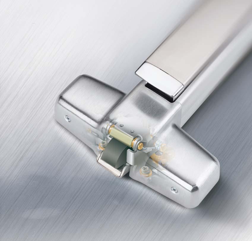
242

243 Introduction XP98/99 Rim Exit Device Balancing security and safety has always been a challenge with any panic exit device design. With the new XP98/99 Rim exit device, Von Duprin has engineered a device that reaches a new standard for security while enhancing the safety performance features. The new patented center case design takes the proven reliability of the 98/99 series and adds a new latch bolt concept that delivers the industry s highest lever of latching security. Additionally, upgrading for current 98/99 owners will be made easy and affordable. The new device will match the existing 98/99 device footprint, eliminating costly door prep changes. A new retrofit kit will allow conversion of existing 99 devices into the new XP99 function, making higher security an affordable function. For over 100 years Von Duprin has set the standard for innovation and quality in the world of exit devices. The XP98/99 Rim device is another page in this long honored story of excellence. XP99 Series features grooved mechanism case. XP98 Series features smooth mechanism case. Von Duprin push pad exit devices are available in two external surface styles, designated XP98 Series and XP99 Series. The two styles are mechanically and dimensionally identical and provide a wide selection of appearance options. Latch Bolt New latchbolt design provides the industry s most secure device. Retro-fit kits available for 98/99 device conversions. The Quiet One A fluid dampener decelerates the pushpad on its return stroke and eliminates most noise associated with exit device operations. Furnished on all XP98/99 series exit devices.
244 XP98/99 Rim Exit Device XP98 and XP99 rim exit devices for all types of single and double doors with mullion, UL listed for accident hazard installations. Covers stock hollow metal doors with 86 or 161 cutouts. XP98-F and XP99-F fire exit rim devices for all types of 4 x 10 (1219mm x 2438mm) single doors or 8 x 10 (2438mm x 2438mm) double doors with 9954 mullion, UL listed A, B, C, D, or E fire labeled installations. 909 Strike Specifications 954 Strike With 9854/9954 Mullion Device Functions Device ships EO/DT/NL. Field selectable. For TP,K,or L remove NL drive screw from device Device Lengths to 3 (711mm to 914 mm) Door Size to 4 (864 mm to 1219 mm) Door Size Strikes 909 Panic and Fire Single Door 954 Mullion Fire Dogging Feature Hex key dogging standard Dogging Options CD Cylinder Dogging SD Special Center Case Dogging LD Less Dogging Electric Options RX Pushpad Monitor Switch* (Consult factory) RX2 Double Pushpad Monitor Switch* E Electric Locking & Unlocking ALK Alarm Exit Kit* Miscellaneous Options -2 Double Cylinder* GBK Glass Bead Kit Fasteners & Includes 1 ³ ₄ (19mm) 2 ¹ ₄ (57mm) Wood & Metal Doors Sex Bolts (SNB) Optional SNB available for device, see next page for quantities Latch Bolt Device Centerline from Finished Floor Center Case Dimensions Mechanism Case Dimensions Projection Deadlocking, ³ ₄ (19mm) throw 39 ¹³ ₁₆ (1011 mm) 39 ¹¹ ₁₆ (1008 mm) with Mullion 8 x 2³ ₄ x 2³ ₈ (203mm x 70mm x 60mm) 2¹ ₄ x 2¹ ₄ (57mm x 57mm) Pushbar Neutral 3 ¹³ ₁₆ (97 mm) Pushbar Depressed 3 ¹ ₁₆ (78 mm) See full-line product catalog for How to Order specification. * Available Q3, Ingersoll Rand. May be copied for use with specification submittal.
245 XP98/99 Rim Exit Device Standard Trim Exit only Dummy Trim Night Latch Night Latch Pull when Dogged Key Retracts Latchbolt Key Retracts Latchbolt Optional Pull Required Product Description Trim Description Escutcheon Plate Size Pull Center to Center Projection ANSI Function Cylinder Type Optional Trim (See pages 32 34) Optional #425 Sex Bolt Quantity for Device XP98EO XP98DT XP98NL XP98NL-OP XP99EO XP99DT XP99NL XP99NL-OP 990DT 990NL-R/V 110NL-MD 110NL-WD 3" x 14³ ₁₆" x ³ ₃₂" 3" x 14³ ₁₆" x ³ ₃₂" (76x360x2mm) (76x360x2mm) 5¹ ₂" (140mm) 5¹ ₂" (140mm) 2" (51mm) 2" (51mm) Rim Rim x990eo x991k-dt x991k-nl x992eo x992l-dt x992l-nl x994eo x994l-dt x994l-nl x996eo x996l-dt x996l-nl x696dt x696nl x697dt x697nl Lever Lever Night Latch Lever Blank Escutcheon Lever Dummy Trim Key Locks & Unlocks Key Retracts Latchbolt Always operable Pull when Dogged (No Cylinder) Product Description Trim Description Escutcheon Plate Size Pull Center to Center Projection ANSI Function Cylinder Type Optional Trim (See pages 32 34) Optional #425 Sex Bolt Quantity for Device XP98L XP98L-NL XP98L-BE XP98L-DT XP99L XP99L-NL XP99L-BE XP99L-DT 996L-R/V 996L-NL-R/V 996L-BE-R/V 996L-DT-R/V 2³ ₄" x 10³ ₄" x ²⁷ ₃₂" 2³ ₄" x 10³ ₄" x ²⁷ ₃₂" 2³ ₄" x 10³ ₄" x ²⁷ ₃₂" 2³ ₄" x 10³ ₄" x ²⁷ ₃₂" (70x273x21mm) (70x273x21mm) (70x273x21mm) (70x273x21mm) 2⁷ ₈" (73mm) 2⁷ ₈" (73mm) 2⁷ ₈" (73mm) 2⁷ ₈" (73mm) Rim Rim x992l x992l-nl x992l-be x992l-dt x994l x994l-nl x994l-be x994l-dt
246


247 Exit Alarm Kit With added features and reengineered design, the new Von Duprin Alarm Kit provides versatility for new or existing applications in any environment. The upgraded Alarm Kit features increased efficiency and provide the performance you have come to expect from Von Duprin while adding improved user interface to allow fast and accurate onsite monitoring and diagnostics. Whatever the environment, the Von Duprin Alarm Kit provides peace of mind in any setting.

248 Features that make the difference ALK Alarm Kit is a simple and effective way to deter unauthorized use of an emergency exit door. Ideal for use on perimeter doors in restaurants, libraries, retail stores and many other commercial business applications. Kits are available for 98, 99, 33, 35 and 22 series exit devices and for all mounting types; rim, mortise and vertical rod. The kit is self-contained and replaces an existing dogging cover. Install is simple; remove the end cap and bracket, slide the dogging cover out and insert the ALK kit. Re-install the end cap and bracket, and the installation is complete. New ALK Battery Operated Alarm Kit offers enhanced features: LED to signal when armed/disarmed. Low battery notification. Tested for extreme temperature environments from -35 to 153 degrees. Improved battery life and efficiency. 24V DC input or 9V battery External Inhibit input Arming and disarming operation is by use of a standard 1-1/4 mortise cylinder. Hardwire Installation: The new ALK assembly includes both a 24VDC input and External Inhibit feature. For continuous operation, the ALK is compatible using the popular PS-861 or other 24VDC power supplies. The External Inhibit provides remote arming and dis-arming. Improved Interface LED display notifies when armed Retrofittable Retrofits Von Duprin ALK in current or older 98/99 models External Inhibit Now comes as a standard feature Optional Battery Can be used to power unit or act as back up 24V DC Input Powered by PS861 or other 24V sources Low Battery Notification Unit will alert user when battery life is low To find out more about the ALK contact your local Ingersoll Rand Security and Safety Consultant or visit Ingersoll Rand Company VD-5794 Rev.12/09


249 Surface Mount Electric Strike 6300 Series Overview The 6300 Series Surface Mount Electric Strike is ideal for aftermarket versatility and migrating existing openings to electronic access control. Its single piece housing and smooth design will reduce interference with traffic while providing durability to external damage. Easy to install without modifying or altering the door frame, this strike can be mounted on any hollow metal, aluminum or wood frame. The 6300 Series Strike was specifically designed for use with the Von Duprin 98/99, however it can be used with most rim exit devices. Features Non-Handed Requires no alteration or cutting to existing frame Field selectable voltage 12-24VDC UL10C Fire Listed up to 3 hours UL1034 Burglary Resistant Stainless steel finish
 3/4\" (19.0mm) HORIZONTAL ADJUSTMENT MOUNTING HOLES 9\" (228.6mm) 8-1/4\" (209.6mm) 5-1/2\" (139.7mm) 1-5/8\" (42.0mm) LOCK DOWN HOLES 877-671-7011 vonduprin.")
250 6300 Surface Mount Specifications Model Voltage Current Duty Amps Ohms V DC Continuous V DC Continuous DC = Direct Current Continuous Duty = Energized 1 min. or more 1-3/4" (44.5mm) 3/4" (19.0mm) HORIZONTAL ADJUSTMENT MOUNTING HOLES 9" (228.6mm) 8-1/4" (209.6mm) 5-1/2" (139.7mm) 1-5/8" (42.0mm) LOCK DOWN HOLES vonduprin.com 2010 Ingersoll Rand ES /10

251 5100 Electric Strike The industry s most versatile electric strike
252 The leader in versatility, convenience and durability Each electric strike kit comes standard with three faceplates, a 12/24 dual-voltage solenoid, fail safe/fail secure selectability and an adjustable keeper. The Von Duprin 5100 Electric Strike has been designed and manufactured to meet the needs of locksmiths and security professionals. This easy-to-install electric strike was created for medium duty applications, specifically to control traffic flow through interior and exterior openings in retail and commercial environments. And because it s the Von Duprin brand, you know that you can depend on the product quality and performance. JOB SITE VERSATILITY. The Von Duprin 5100 Electric Strike can meet the application needs of six or more competitive models for standard installation, which saves time, money, and labor. 1. The solenoid has four wires, allowing you to configure the strike at the job site so you can use it in either 12 or 24 volt DC applications. 2. The 5100 Electric Strike is easily changeable between fail-safe and fail-secure in the field without the need for additional parts. VERSATILITY: Fewer products to inventory and more value for your money. Three faceplates included for hollow metal, wood or aluminum frames. Internal 12/24 dual-voltage solenoid. Adjustable keeper. Fail-safe/fail-secure selectability. CONVENIENCE: The right parts in the box means getting the job done right the first time, every time. Reduce labor expense. Fewer return trips to the job site. Reduces SKU s. DURABILITY: Developed with Von Duprin s high standards and engineering expertise. Heavy-duty construction. Tamper resistant design. Tested to over one million cycles lbs. holding strength. 3. The 5100 Electric Strike has a 1/8" horizontally adjustable keeper. This mechanism, which is designated by the dark gray region of the diagram, allows the installer to adjust the strike where a door and frame are not properly aligned or where weather stripping is causing too much pressure on the strike. 1/8" adjustable 2
253 Standard Features Three faceplates standard in every box Benefits No matter the frame type -- wood, aluminum or hollow metal -- the installer has what s needed in every box to finish the job right the first time. 12/24 dual-voltage Easily answers the question of 12 or 24 volts DC. Fail-safe/fail-secure Adjustable keeper Internal solenoid Non-handed Backbox depth of " Keeper depth of 1 2" Mounting tabs Retrofit kit Illustrated installation instructions Tamper resistant design Warranty Continuous duty operation Heavy duty construction Easily changed in the field in less than thirty seconds. No additional parts are required. Provides a snug fit and reduces pressure from the door on the strike. Increases the ease of installation where the frame is filled with grout or concrete and must be hollowed-out. Can be used for doors opening in either direction. Reduces the need for additional cutting of the frame and other prep work. Sufficient to accommodate all cylindrical locks up to 5 /8" throw and most aluminum narrow stile deadlatches. For applications where mounting brackets are not provided on the frame. Neoprene filler provides a clean finish. Increases ease of use and installation. Minimizes unauthorized access. Standard Von Duprin 1 year electrical product warranty. Solenoid can be continuously powered. Die cast aluminum backbox offers strong, corrosion resistant design. Internal steel components are corrosion resistant. High density steel keeper can withstand over 1300 lb. of force. Stamped steel faceplates are stronger than aluminum 5/32" radius on 4 corners 3-31/32" 3-23/32" 5/32" radius on 4 corners (Aluminum frame) 1-1/16" 1-1/2" 1" 7-7/16" 2-7/16" 2-1/16" 1-11/16" 1-11/16" 7-15/16" 4-7/8" 4-1/8" C strike L 3-3/8" 31/32" 3/32" 1-7/16" 31/32" 23/32" 1-1/4" 5/8" C Lock and strike L C Lock and strike L 3
254 5100 Electric Strike The industry s most versatile electric strike. POWER OPTIONS: DC: Regulated Power Supplies (Recommended) Von Duprin PS 861 Von Duprin PS 873 Locknetics 505 Locknetics 510 Locknetics 515 DC: 24V Unregulated Power Supplies (Acceptable) Locknetics 593 PI-24DC (Plug-In) Locknetics RC (Hard-Wired) AC/DC Conversion: Von Duprin SO-24 Kit SPECIFICATIONS: ANSI/BHMA Grade 1 UL 1034 Burglary Listing 12VDC 24VDC Resistance (Ohms) Power (watts) Current (amps) All specs ± 77 F/25 C DIMENSIONS: Backbox: 3 3 8" x 1" x " Overall Strike Depth: " Faceplates: 4 7 8" round corner ANSI A115.2 standard frame prep 4 7 8" square corner ANSI A115.2 standard frame prep " long, round corner wood frame prep Keeper pocket: "L x 1 2"D x 11 16" "W (adjustable) Lip Attachment cut-out depth: " HOW TO ORDER: (Aluminum) (Black) (Dark Brown) STANDARD CONFIGURATION: 24 volts DC Fail-secure Ingersoll-Rand Form VD-GN-1147 Rev. 8/03 Printed in USA VON DUPRIN 2720 Tobey Drive, Indianapolis, IN phone fax

255 GUARD-X Exit Alarm Lock

256 Exit Alarm Lock Large, Stainless Steel Deadbolt 100-Decibel Horn Optional Outside Operation Signage Includes Braille Impact Resistant Endcap Deadlocking Standard 9-Volt Battery Nonhanded Alarmed Indicator Light Low-Battery Alert Cast Aluminum Latch Cover Patent Pending GUARD-X provides secure, alarmed code-compliant protection for secondary exits. GUARD-X exit alarm lock readily identifies the door on which it is mounted as an emergency exit and secures the opening against unauthorized use. It is ideal for deterring theft in restaurants and retail establishments such as: discount stores, grocery stores, drug stores, clothing stores and sporting goods stores. Heavy-Duty Design The new Series 2670 Exist Alarm Lock provides secure protection through a large stainless steel deadbolt, which is 2" x 1/2" (51mm x 13mm) and has over a 3/4" (19mm) throw. The engagement area into the strike is over 1-1/4 (32mm) square inches. The cast aluminum latch case protects the internal mechanism and resists tampering or vandalism from inside the door. This unit has been tested to withstand up to 1600 pounds of static load force against the door. Security GUARD-X does not allow relatching or resetting the alarm after an unauthorized exit, other than by an authorized person with a key. A 100-decibel alarm provides a clear, attention-getting warning for an unauthorized exit or attempted exit. The armed indicator light informs the owner that the alarm is armed, and an audible low-battery alert signals the owner to replace the battery when necessary. Compliance GUARD-X complies with the NFPA 101 Life Safety Code the actuating portion of which extends across at least one half of the door leaf. It is UL listed for Panic Exit Hardware (UL305) including the ends of the crossbar or push pad shall curve, guard, or are otherwise designed to prevent catching on the clothing of persons during exit for use on Emergency Exit applications, and tested in accordance to ANSI A156.3 Grade 1 Panic Hardware (250,000 cycles). Installation takes just a few minutes with an easy-to-use adhesive back template. The product s nonhanded design means the installer can mount it for either hand by just removing and reversing the Emergency Exit Alarm Will Sound sign built into the device. The standard warning sign is in English with Braille; French and Spanish are available. Operation and Outside Trim GUARD-X is armed and disarmed by key, using a standard rim cylinder. For owner convenience, it can be operated from the building exterior by a standard rim cylinder, so an authorized user can easily arm and disarm it to enter or exit the building when required. When using exterior operation, a pull trim is recommended, use 210DT or 230DT. Rim cylinders are not furnished and must be ordered separately. A standard 9-volt battery powers the alarm. An exterior 9-volt power supply is available, Model PT-790, a 120VAC plug-in. When using the external power supply, the 9-volt battery functions as a battery backup during a power failure Ingersoll-Rand. May be copied for use with specification submittal.
, anodized duranodic dark bronze (313AN/710) and anodized black (315AN).")
 3 (76mm) 12-1/16 (306mm) 4-1/8 (105mm) 4-25-32 (171mm) Outside Trim 210DT 1-31/32 (50mm) Projection 230DT 2 (51mm) Projection Touchbar height to finished floor Door width range Touchbar")
, 313AN (Duranodic Brown), 315AN (Black) How-To Order 1. Model number 2670 (includes strike, screw pack and battery) 2. Finish US28, 313AN or 315AN 3.")
257 Secure and Code Compliant Large 2 x 1/2 stainless steel deadbolt provides maximum security. A Standard rim cylinder is used to arm or disarm lock. Heavy-duty construction provides long service life. Three finishes available, including aluminum (US28), anodized duranodic dark bronze (313AN/710) and anodized black (315AN). Dimensions Exist Alarm Lock 2-3/4 (70mm) 4-7/8 (124mm) 1-1/4 (32mm) 267* Roller Strike 2609 Double Door Strike 3/4 (19mm) 7 (179mm) 4-1/16 (109mm) EMERGENCY EXIT ONLY ALARM WILL SOUND 32-1/2 (826mm) 5-3/4 (146mm) 3 (76mm) 12-1/16 (306mm) 4-1/8 (105mm) (171mm) Outside Trim 210DT 1-31/32 (50mm) Projection 230DT 2 (51mm) Projection Touchbar height to finished floor Door width range Touchbar projection neutral depressed Latch case housing Device length 40 (1016mm) at center 36 (914mm) to 48 (1219mm) 4-1/8 (103mm) 2-3/4 (70mm) 7 (179mm) x 4-1/16 (103mm) x 4-1/8 (105mm) 32-1/2 (826mm) Finishes US28 (Aluminum), 313AN (Duranodic Brown), 315AN (Black) How-To Order 1. Model number 2670 (includes strike, screw pack and battery) 2. Finish US28, 313AN or 315AN 3. French or Spanish sign, when required. English with Braille is standard. Accessories 4. Sex nuts and bolts (6 #325) when required 5. PT790 9-volt External Power Supply when required DT x or 230DT x when required Rim Cylinder, when required *2609 double door strike available.
22 Series Exit Devices
 22 Series Exit Devices 22 Exit Device Finishes Color US Number BHMA Number Sprayed Aluminum SP28 689 Sprayed Dark Bronze SP313 695 2005 Ingersoll-Rand Co. May be copied for use with specification submittal.
22 Series. Exit device
 22 Series Exit device Introduction Exit devices are a critical part of the Fire and Life Safety egress system and will provide safe and reliable service when properly applied and maintained. Von Duprin
22 Series. Exit device
 22 Series Exit device Introduction Exit devices are a critical part of the Fire and Life Safety egress system and will provide safe and reliable service when properly applied and maintained. Von Duprin
22 Series. Exit device
 22 Series Exit device Introduction Built to protect Von Duprin products symbolize a commitment to safety and security. It s evident in the meticulous engineering behind every exit device. After all, keeping
98/99 Series Exit Devices
 98/99 Series Exit Devices 98/99 Finishes Finishes* Color US Number BHMA Number Chromium, Polished US26 625 Anodized, Aluminum US28 628 Chromium, Dull US26D 626 Brass, Polished US3 605 Brass, Dull US4 606
22 Series. Exit device
 22 Series Exit device Introduction Exit devices are a critical part of the Fire and Life Safety egress system and will provide safe and reliable service when properly applied and maintained. Von Duprin
Precision List Prices
 Precision List Prices Item Number Description[1] List Price 2260589 1200 SERIES PULLMAN TOP LATCH 250.00 01053-53 18 CENTER CAM ASSY RETAINER 8.60 2101 612 48 2100 APEX RIM EXIT DEVICE 1156.00 2101 630
33A/35A Series Exit Devices
 33A/35A Series Exit Devices Introduction The proper selection and application of exit hardware, in addition to safety, are major concerns to all responsible manufacturers. Exit devices are a critical part
33A/35A Series. Exit devices
 33A/35A Series Exit devices Introduction The proper selection and application of exit hardware, in addition to safety, are major concerns to all responsible manufacturers. Exit devices are a critical part
33A/35ATM. Series. Exit Devices
 33A/35ATM Series Exit Devices Introduction The proper selection and application of exit hardware, in addition to safety, are major concerns to all responsible manufacturers. Exit devices are a critical
33A/35A Series. Exit devices
 33A/35A Series Exit devices Introduction The proper selection and application of exit hardware, in addition to safety, are major concerns to all responsible manufacturers. Exit devices are a critical part
33A/35A Series. Exit devices
 33A/35A Series Exit devices Introduction Invest in longevity Von Duprin devices are engineered to add value over time. The robust materials and unique engineering add to the longevity, while the flexible
98/99 Series. Exit devices
 98/99 Series Exit devices Introduction Exit devices are a critical part of the fire and life safety egress system and will provide safe and reliable service when properly applied and maintained. Von Duprin
98/99 Series. Exit devices
 98/99 Series Exit devices Introduction Exit devices are a critical part of the fire and life safety egress system and will provide safe and reliable service when properly applied and maintained. Von Duprin
9827/9927 Surface mounted vertical rod device. 9827/9927 Surface mounted vertical rod device. Specifications Device functions
 Top latch 299 Top strike for all types of single or double doors, UL listed for panic exit hardware. Devices are ANSI A56.3 200 Grade. Covers stock hollow metal doors with 86 or 6 cutouts. The 9827 device
98/99TM. Series. Exit Devices
 98/99TM Series Exit Devices Introduction Exit devices are a critical part of the Fire and Life Safety egress system and will provide safe and reliable service when properly applied and maintained. Von
98/99 Series. Exit devices
 98/99 Series Exit devices Introduction Exit devices are a critical part of the fire and life safety egress system and will provide safe and reliable service when properly applied and maintained. Von Duprin
98/99 Dogging options
 98/99 Dogging options CDSI/HDSI dogging indicators Indicator provides an at-a-glance verification of the status of the door from inside of the room. Visible LOCKED and UNLOCKED indicators show whether
98/99 Series. Exit device
 98/99 Series Exit device Introduction Engineered for value Von Duprin devices are designed with our customers in mind. The robust materials and unique engineering add to the longevity of our products,
9849/9949 Concealed Vertical Cable Device
 9849/9949 Concealed Vertical Cable Device Top Latch 9849/9949 Concealed Vertical Cable Device 32 Hex key comes standard on 9849/9949 Concealed Vertical Cable Devices 9849/9949 concealed vertical cable
Adams rite. Exit Devices & parts exit devices series exit device parts
 Adams rite Exit Devices & parts exit devices 8099 8211 8099 Active Dummy Bar with Switch Can be wired normally open or normally closed to operate maglock, alarm, etc No latching mechanism 8211 Surface
ABS-AMERICAN BUILDING SUPPLY, INC. Von Duprin
 22 - Rim Device 22 rim device for all types of single and double doors with mullion, UL listed for accident hazard installations. Covers stock hollow metal doors with 161 cutouts. Fits door stiles as narrow
ADDITIONAL INFORMATION
 ADDITIONAL INFORMATION How to Order Sequence Example Prefixes CD AE DM KOR LK LM ED Rating F Blank Cylinder Dogging Touchbar Request to Exit Latchbolt and Device Monitor Switch Key Bypass Switch Locking
ADDITIONAL INFORMATION
 ADDITIONAL INFORMATION How to Order Sequence Example Prefixes CD AE DM KOR LK LM ED Rating F Blank Cylinder Dogging Touchbar Request to Exit Latchbolt and Device Monitor Switch Key Bypass Switch Locking
9827-F/9927-F Surface Mounted Vertical Rod Fire Device
 9827-F/9927-F Surface Mounted Vertical Rod Fire Top Latch 299F Top Strike 304L Bottom Strike 499F Top Strike - LBR Bottom Latch 9827-F/9927-F fire exit surface mounted vertical rod device pairs of doors
Olympian 100, 200, 300 Series
 OLYMPIAN 100, 200, 300 SERIES : EXIT DEVICES Olympian 100, 200, 300 Series Exit Devices Strength by design. Simply PRECISION TABLE OF CONTENTS Exit Devices & Trims Rim Devices...4, 5 Surface Vertical Rod
RELIANT 5000 SERIES: EXIT DEVICES. Reliant 5000 Series. Exit Devices. Strength by design. Simply PRECISION
 RELIANT 5000 SERIES: EXIT DEVICES Reliant 5000 Series Exit Devices Strength by design. Simply PRECISION TABLE OF CONTENTS Exit Devices & Trims Rim Devices...4, 5 Surface Vertical Rod Devices...6, 7 Mullions
PUSH BAR EXIT DEVICES CROSS BAR EXIT DEVICES NARROW STILE EXIT DEVICES FEATURING LCWD STRIKES... 20
 Exit Devices Section TABLE OF CONTENTS EXIT DEVICES PUSH BAR EXIT DEVICES N1500 Heavy Duty Rim Exit Device N1550 Rim Exit Device... 6 N1650 Fire Rated Heavy Duty Exit Device N1700(F) Vertical Rod Heavy
Dor-O-Matic Exit Devices
 Dor-O-Matic Exit Devices T H E F A L C O N D I F F E R E N C E S A F E T Y, S E C U R I T Y A N D U N C O M P R O M I S I N G V A L U E At Falcon, we know that every product you sell not only has to meet
PARTS MANUAL 3327A/3527A SERIES EXIT DEVICES JUNE A SHOWN. PM3327A3527A_b VD Copyright 2005 Ingersoll-Rand. All rights reserved.
 PARTS MANUAL JUNE 005 A/5A SERIES EXIT DEVICES 5A SHOWN PMA5A_b VD-4050 Copyright 005 Ingersoll-Rand. All rights reserved. INDEX A/5A Fire and Panic Devices Basic Device... 4-5 Vertical Rods and Latches...
99 Series Exit devices
 99 Series Exit devices Fire Rated: Tested on fire door assemblies in accordance with Australian Standards, refer fire door manufacturer for specific approval details The Von Duprin 99 Series is a contemporary
VON DUPRIN 2720 TOBEY DRIVE INDIANAPOLIS, IN CERTIFIED EXIT DEVICES
 VON DUPRIN 2720 TOBEY DRIVE INDIANAPOLIS, IN 46219 877-671-7011 CERTIFIED EXIT DEVICES Models listed in the UL Online Certification Directory as conforming to the American National Standard for Exit Devices
ARCHITECTURAL DOOR HARDWARE EXIT DEVICE CATALOG
 ARCHITECTURAL DOOR HARDWARE EXIT DEVICE CATALOG January 1, 2017 v3 West Coast Office (800) 544-4422 East Coast Office (800) 225-6737 intldoorclosers.com Index EXIT DEVICES 5000 Series (Grade 2)...1-10
Auxiliary hardware & general information. Exit devices
 Auxiliary hardware & general information Exit devices Introduction Since pioneering the first exit device in 1908, Von Duprin life safety products have provided unparalleled quality, performance and flexibility
PARTS MANUAL 98/99 SERIES RIM EXIT DEVICES. May RIM 98 RIM PM9899_G VD-GN Copyright 2013 Ingersoll Rand
 PARTS MANUAL May 0 9/99 SERIES RIM EXIT DEVICES 99 RIM 9 RIM PM999_G VD-GN-09 Copyright 0 Ingersoll Rand INDEX 9/99 Rim Devices Basic Panic Device... Basic Fire Device... Baseplate Assemblies... Center
CAL-ROYAL & F2200 Rim Type Panic And Fire Exit Devices 2260 & F2260 Vertical Rod Panic And Fire Exit Devices ANSI A156.
 CAL-ROYAL P R O D U C T S, I N C. 3 HOUR FIRE RATED 2200 & F2200 Rim Type Panic And Fire Exit Devices 2260 & F2260 Vertical Rod Panic And Fire Exit Devices ANSI A156.3, Grade 1 Lifetime Warranty BHMA CERTIFIED
EXIT DEVICES Reliant 5000 Series
 PRECISION HARDWARE EXIT DEVICES Reliant 5000 Series GENERAL INFORMATION TABLE OF CONTENTS EXIT DEVICES & TRIMS Page Rim Devices...4, 5 Surface Vertical Rod Devices...6, 7 MULLIONS Fire Labeled Removable
PARTS MANUAL 3327A/3527A SERIES EXIT DEVICES FEBRUARY A SHOWN. PM3327A3527A_d VD Copyright 2013 Ingersoll Rand
 PARTS MANUAL FEBRUARY 0 A/5A SERIES EIT DEVICES 5A SHOWN PMA5A_d VD-050 Copyright 0 Ingersoll Rand INDE A/5A Fire and Panic Devices Basic Device... Vertical Rods and Latches... LBR Fire Latch Kit... Baseplate
PARTS MANUAL 98/9927 SERIES EXIT DEVICES MAY 2013 PM989927_G VD-GN Copyright 2013 Ingersoll Rand
 PARTS MANUAL MAY 0 9/99 SERIES EIT DEVICES VD-GN- Copyright 0 Ingersoll Rand INDE 9/99 Devices Basic Panic Device... Basic Fire Device... Vertical Rods and Latches... Baseplate Assemblies... Center Case
Recessed. Touch bar exit devices
 Recessed Touch bar exit devices Table of contents 3 2390 Concealed vertical rod device 4 Accessories 5 Power supply 6 Door application 7 How to order The Falcon difference Safety, security and uncompromising
The following changes were made to the Von Duprin Price Book 3 Rev 10/15:
 Brand/Product Von Duprin Date April 4, 2016 Subject 2016 Q2 Von Duprin Price Book Changes The following changes were made to the Von Duprin Rev 10/15: Page 56, 58 Remove US15 pricing from 98/9975HL Page
OLYMPIAN 100, 200, 300 SERIES PRECISION HARDWARE
 OLYMPIAN 100, 200, 300 SERIES PRECISION HARDWARE GENERAL INFORMATION TABLE OF CONTENTS EXIT DEVICES & TRIMS Page Rim Devices...4, 5 Surface Vertical Rod Devices...6, 7 Mortise Devices...8, 9 MULLIONS Fire
Recessed. Exit Device Series
 Recessed Exit Device - 2390 Series Table of Contents 2390 Concealed Vertical Rod Device 3 Accessories 4 Power Supply 5 Door Application 6 How To Order 7 F A L C O N E X I T D E V I C E S Architectural
ADAMS RITE. ADAMS RITE MANUFACTURING COMPANY Sliding Hardware/Exit Devices Series Turns
 Sliding Hardware/ 1000 Series Turns Series 1000 turns are designed to operate Adams Rite MS 1847 deadlocks and latches. 1000-11 and 1000-21 have a rectangular escutcheon for mounting directly on the door.
DOOR HARDWARE SPECIFICATION GUIDELINE SECTION
 CHABOT-LAS POSITAS COMMUNITY COLLEGE DISTRICT 5020 FRANKLIN DRIVE, PLEASANTON, CA 94588 925-485-5215 DOOR HARDWARE SPECIFICATION GUIDELINE SECTION 087100 April 2008 CHABOT-LAS POSITAS COMMUNITY COLLEGE
APEX 2000 SERIES: TOUCHBAR EXIT DEVICES. Apex 2000 Series. Touchbar Exit Devices. Strength by design. Simply PRECISION
 APEX 2000 SERIES: TOUCHBAR EXIT DEVICES Apex 2000 Series Touchbar Exit Devices Strength by design. Simply PRECISION TABLE OF CONTENTS Wide Stile Exit Devices & Trims Rim Devices...4, 5 Surface Vertical
2227 Series Vertical Rod Exit Device. Service manual
 7 Series Vertical Rod Exit Device Service manual INDEX 7 Vertical Rod Devices Basic Panic Device... 4-5 Basic Fire Device... 6-7 Vertical Rods and Latch Cases... 8-9 Baseplate Assemblies... 0 Center Case
Door control and security hardware
 Door control and security hardware Introduction Since pioneering the first exit device in 908, Von Duprin life safety products have provided unparalleled quality, performance and flexibility for schools,
22 Series Rim Exit Device. Service manual
 Series Rim Exit Device Service manual INDEX Rim Devices Basic Panic Device... 4-5 Basic Fire Device... 6-7 Baseplate Assemblies... 8 Center Case Assembly... 9 Variations of the Basic Device RX (Request
98/99 Series Rim Exit Devices
 98/99 Series Rim Exit Devices Service manual 99 RIM 98 RIM INDEX 98/99 Rim Devices Basic Panic Device... Basic Fire Device... Baseplate Assemblies... Center Case Assembly... Variations of the Basic Device
PARTS MANUAL 33A/35A SERIES RIM EXIT DEVICES JUNE A RIM 35A RIM. PM33A35A_Rim_B VD Copyright 2005 Ingersoll-Rand. All rights reserved.
 PARTS MANUAL JUNE 005 A/5A SERIES RIM EXIT DEVICES A RIM 5A RIM PMA5A_Rim_B VD-4049 Copyright 005 Ingersoll-Rand. All rights reserved. INDEX A/5A Rim Panic Devices Basic Device... 4-5 Baseplate Assembly...
3327A/3527A Series Exit Device
 A/5A Series Exit Device Service manual 5A SHOWN INDE A/5A Fire and Panic Devices Basic Device... Vertical Rods and Latches... LBR Fire Latch Kit... Baseplate Assembly... 4-5 - 9 Variations of the Basic
ED5470 Panic-Listed Surface Vertical Rod Exit Device ED5470B 1-1/2 Hour Fire-Listed Surface Vertical Rod Exit Device
 Surface Vertical Rod Features ED5470 Panic-Listed Surface Vertical Rod Exit Device ED5470B 1-1/2 Hour Fire-Listed Surface Vertical Rod Exit Device Features Handing Device is handed but easily field reversible.
20 Series. Exit Device
 20 Series Exit Device Copyright 2003, 2007, 2009, Sargent Manufacturing Company, an ASSA ABLOY Group company. All rights reserved. Table of Contents Table Of Contents Page Features, Applications and UL
Table Of Contents. 30 Series Exit Device. On The Cover
 30 Series Exit Device Copyright 1999, 2001, 2004, 2008, 2009, Sargent Manufacturing Company, an ASSA ABLOY Group company. All rights reserved. Table Of Contents Page Features, Applications and UL Fire
EXIT DEVICES Apex 2000 Series
 PRECISION HARDWARE EXIT DEVICES Apex 2000 Series GENERAL INFORMATION TABLE OF CONTENTS WIDE STILE EXIT DEVICES & TRIMS Page Rim Devices...4, 5 Surface Vertical Rod Devices...6, 7 Mortise Devices...8, 9
PARTS MANUAL 98/9947 & 98/9949 SERIES EXIT DEVICES OCTOBER / /9949 VD-GN Ingersoll Rand Rev.
 PARTS MANUAL OCTOBER 0 9/99 & 9/999 SERIES EIT DEVICES 9/99 9/999 VD-GN-0 0 Ingersoll Rand ---0 99 Rev. 0/_f INDE 9/99 & 9/999 Devices Basic Device... - Panic and Fire Metal Door Concealed Vertical Rods
PARTS MANUAL 33/3547A & 33/3549A SERIES EXIT DEVICES OCTOBER /3547A 33/3549A VD Ingersoll Rand Rev.
 PARTS MANUAL OCTOBER 0 /5A & /59A SERIES EIT DEVICES /5A /59A VD-05 0 Ingersoll Rand -8--0 90 Rev. 0/_e INDE /5A & /59A Devices Basic Device... -5 Panic Concealed Vertical Rods and Latches... - Fire Concealed
5000 & F5000 Rim Type Panic And Fire Exit Devices 5000V & F5000V Vertical Rod Panic And Fire Exit Devices ANSI A156.3, Grade 2
 5000 & F5000 Rim Type Panic And Fire Exit Devices 5000V & F5000V Vertical Rod Panic And Fire Exit Devices ANSI A156.3, Grade 2 Features & Construction ANSI A156.3, Grade 2 heavy duty exit device in surface
8500 Narrow Design Rim Exit Device 80 Series
 8500 Narrow Design Rim Exit Device 8500 Series Narrow Design Rim Exit Device Specifications for 8500 Series Exit Door Types Rail sizes as determined by door width Strike Dogging Feature Electric Mounting
EXIT DEVICES. philihardware.com
 EXIT DEVICES philihardware.com UL Introduction GENEAL INFOMATION ADVANTAGE exit devices are designed and manufactured in accordance to ISO9001 QMS and certified by BHMA. All ADVANTAGE exit devices are
8800 Rim Exit Device 80 Series
 8800 Rim Exit Device 8800 Series Rim Exit Device 8800 Features Designed for standard width stile applications on wood and metal doors Also available as an HC8800 or WS8800 for hurricane-resistant applications,
8888/8810 Multi-Function Rim Exit Device & Trim 80 Series
 8888/8810 Multi- Rim Exit Device & Trim The 8888/8810 Rim Exit Device Devices are A156.3 UL Fire and Panic listed Device is non-handed /BHMA architectural finishes Four standard sizes available To Order:
Concealed Vertical Rod Features
 Concealed Vertical Rod Features ED5800 Panic-Listed Concealed Vertical Rod Exit Device ED5800A 3-Hour Fire-Listed Concealed Vertical Rod Exit Device FOR USE WiTH METAL DOORS OnLy Features Handing Device
Table of Contents 20 Series Exit Device
 20 Series Exit Device Copyright 2003, 2007, 2009-2012, Sargent Manufacturing Company, an ASSA ABLOY Group company. All rights reserved. Table of Contents Features, Applications and UL Fire Door Ratings...
Spectra Class. N6000 Series Exit Devices SECURITY DOOR CONTROLS. N6100 Rim Mount Exit Device. N6200 Surface Vertical Rod Exit Device.
 N6000 Series Exit Devices Spectra Class Rim Mount Surface Vertical Rod N6100 Rim Mount Exit Device For use on single doors or pair of doors with mullion 1-3/4"(44 mm) door thickness standard. Specify thickness
98/9947, 98/9949, & 98/9950 Series Exit Devices
 98/99 98/99, 98/999, & 98/990 Series Exit Devices 98/999 Service manual 98/990 INDE 98/99, 98/999, & 98/990WDC Devices Basic Device... - Panic and Fire Metal Door Concealed Vertical Rods and Latches...
33A/35A Series Rim Exit Device
 A/5A Series Rim Exit Device Service manual A RIM 5A RIM INDEX A/5A Rim Panic Devices Basic Device... -5 Baseplate Assembly... Variations of the Basic Device CD (Cylinder Dogging)... HD-EL (Hex Dogging/Electric
Spectra Class - Specification Grade Exit Devices for superior Architectural Style & Performance
 S6000 & N6000 Spectra Exit Devices Spectra Class - Specification Grade Exit Devices for superior Architectural Style & Performance The new mechanical SDC S6000 & N6000 Spectra series panic and fire rated
Catalog Cuts. for DENTON ISD. Prepared By DENTON ISD DENTON, TEXAS. NoPrjNum. PDF created by Specworks. created 11/01/ :29:06 AM
 Catalog Cuts for DENTON ISD Prepared By DENTON ISD DENTON, TEXAS NoPrjNum created 11/01/2006 10:29:06 AM 7800/8200 MORTISE LOCKS 7800/8200 Mortise Locks Features 1-800-727-5477 www.sargentlock.com SARGENT
Entry. Entry. Entry. Entry
 Functions x 9800/9M800 AC2 Exit Device Outside Inside Series/Function Type Function Description ED5200(A) & ED5200S(A) *9833 Without Cylinder Outside lever locked (freewheeling) except when in passage
An ASSA ABLOY Group brand Series. Flatbar Exit Devices
 An ASSA ABLOY Group brand 1800 Series Flatbar Exit Devices introduction Yale 1800 series exit devices are the ideal choice for economy commercial applications where consistent quality, ease of use and
8800 Rim Exit Device 80 Series
 8800 Rim Exit Device 8800 Series Rim Exit Device 8800 Features Designed for standard width stile applications on wood and metal doors Also available as an HC8800 or WS8800 for hurricane-resistant applications,
8800 Rim Exit Device 80 Series
 8800 Rim Exit Device 8800 Series Rim Exit Device 8800 Features Designed for standard width stile applications on wood and metal doors Also available as an HC8800 or WS8800 for hurricane-resistant applications,
Exit Devices Rainer Security Products Ltd
 Exit Devices Rainer Security Products Ltd Unit B6, Rudford Industrial Estate, Ford, Arundel, West Sussex BN18 0BF +44 (0) 190 72211 rainersecurity.co.uk sales@rainersecurity.co.uk 2 S1150 & S1250 Series
ED8000 Series. Pushpad Exit Devices
 Series Pushpad Exit Devices Introduction Table of Contents Introduction...2 Applications and Listings... 3 Rim Exit Features...4 Surface Vertical Rod Exit Features...6 Rim/Vertical Rod Trims and Functions...8
55 Series Exit devices
 55 Series Exit devices The Von Duprin 55 Series is a range of push bar exit devices designed to suit single and double door applications with narrow stiles. The 55 Series can be used on aluminium hollow
Exit Devices TABLE OF CONTENTS. Top or Bottom Rod Replacement Kit Trim Handing Pin... 43
 Exit Devices TABLE OF CONTENTS A Accessories, 4500 Series Grade 1 Alarm Kit... 25 Alarm Kit Latchbolt Monitor Switch... 28 Alarm Kit Tamper Switch... 29 Concealed Vertical Rod Bottom Latch Assembly...29
MA Series. Mortise Lockset Functions. MA101 FO1 Passage Latchset Latchbolt by knobs/levers at all times.
 MA Series Mortise Lockset Functions ANSI MA101 FO1 Passage Latchset Latchbolt by knobs/levers at all times. MA301 F02 Privacy Lock Latchbolt by knobs/levers, deadbolt by turn inside or emergency key outside.
ED7000 Series. Narrow Stile Crossbar Exit Devices
 Narrow Stile Crossbar Exit Devices Applications Narrow Stile Crossbar Exit Devices Table of Contents Applications... 2 Applications and Listings... 3 Features, Trims and Functions Rim Exit... 4 Mullions...
ED5000 Series. Pushpad Exit Devices
 Pushpad Exit Devices Overview Table of Contents Overview... 2 Product Series Features... 3 Applications and Listings... 4 SecureBolt Features... 6 Rim Features... 8 Surface Vertical Rod Features... 10
Table of Contents 30 Series Exit Device
 30 Series Exit Device Table of Contents Features, Applications and UL Fire Door Ratings... 1 3727/ NB3727 Vertical Rod Type Exit Device... 2 3828 Rim Type Exit Device...3 30 Series Trims....4 Alternate
19 Series Touch Bar Exit Device
 9 Series Touch Bar Exit Device Monarch Hardware offers handcrafted quality exit door hardware at an affordable price. As part of IR Security & Safety, Monarch Hardware has the resources to meet the quality
Overhead Door Holders/Stops
 Overhead Door Holders/Stops 08 71 00/ING BuyLine 7155 STEELCRAFT SINGLE ACTING DOORS, INTERIOR/EXTERIOR APPLICATIONS, REVERSIBLE, NON-HANDED 450 Series Surface-mounted holders and stops offer the widest
4000 Series Exit Devices Premier Product
 4 4000 Series Exit Devices Premier Product Certification & Compliance: u ANSI/BHMA A56., Grade ANSI A7. Accessibility Code Underwriters Laboratories (UL and CUL) listed for accident hazard (panic) standard.
08710/ING BuyLine 7155
 08710/ING BuyLine 7155 LOCKNETICS ON BOARD LOCKNETICS RECOGNITION SYSTEMS VON DUPRIN GLYNN-JOHNSON IVES LCN SCHLAGE DOR-O-MATIC STEELCRAFT 80 USA 1.877.613.8766 Canada 1.905.278.6128 www.glynn-johnson.com
ED3000 Series. Crossbar Exit Devices
 Crossbar Exit Devices Introduction Table of Contents Applications and Listings... 3 Functions... 4 Rim Exit Features... 5 Surface Vertical Rod Exit Features... 7 Mortise Exit Features... 9 Trims and Functions...
DOUBLE LEVER ARM DOUBLE LEVER ARM SINGLE LEVER ARM 5010 SINGLE LEVER ARM
 SERIES PRODUCT SELECTION GUIDE The concealed LCN closers feature a modern design for concealment in either the head frame or top rail of the door. This guide is based on the desired mounting of the closer.
MA Series. Mortise Lockset Functions. MA101 FO1 Passage Latchset Latchbolt by knobs/levers at all times.
 MA Series Mortise Lockset Functions ANSI MA101 FO1 Passage Latchset Latchbolt by knobs/levers at all times. MA301 F02 Privacy Lock Latchbolt by knobs/levers, deadbolt by turn inside or emergency key outside.
CONCEALED CLOSER SERIES
 CLOSER SERIES PRODUCT SELECTION GUIDE The concealed LCN closers feature a modern design for concealment in either the head frame or top rail of the door. This guide is based on the desired mounting of
55 Series Exit Devices. Service manual
 55 Series Exit Devices Service manual INDEX General Information Introduction... How to Order... Part Number Changes... 55 Series Finishes... 3 Outside Trim Functions... 3 Strikes... 55 Series Device Parts
Standard Lever Designs
 Standard Lever Designs 3-7/8" 96mm 4-3/4" 121 mm 01 64mm 02 2-15/16" 75 mm 1/2" 13mm 4-5/8" 117mm 4-5/8" 117mm 06 2-3/4" 73mm 07 3-5/8" 92mm 4-7/8" 124 mm 4-7/8" 124 mm 18 2-5/8" 67 mm Accent (ACC) Material:
5/8" Radius Corner Hinges
 5/8" Radius Corner Hinges FULL MORTISE 5 Knuckles Removable Pin Steel with Steel Pin Non-Template Pack with Phillips flat-head screws (machine and wood) H44-50R SPRING HINGE UL Listed Steel with Steel
8000 Series. Grade 1 exit device. Equia nestotatus enis 2015
 8000 Series Grade 1 exit device Equia nestotatus enis 2015 Lecest Suntur Orem fuga Equia nestotatus Disciisi nisquissus Nequisi Voloreptatae Consecumque soloribus Iminveria volorum dormakaba 8000 Grade
TABLE OF CONTENTS StrikeForce Electric Strikes MAX HOLD Electromagnetic Locks Electrical Accessories Additional Information
 TABLE OF CONTENTS StrikeForce Electric Strikes............................ 4-3 Series 6000 Electric Strikes........................... 4-3 Strikes for Rim Exit Devices.......................... 5-6 Strikes
2100 Series. Flatbar Exit Devices. An ASSA ABLOY Group brand
 2100 Series Flatbar Exit Devices An ASSA ABLOY Group brand rugged reliability Yale 2100 introduction It s no secret that the 2100 series flatbar exit device has a reputation as the right choice for meeting
Electrical Options Booklet. Table of Contents
 *24228413* 24228413 Electrical Options Booklet Table of Contents EL Wiring... EL Troubleshooting... SD/EL 98/99 Cylinder Dogging... SS Wiring... 330, 350, RX-330 and RX-350 Push Bar Trim Mechanical Installation...
SERIES 700 TECHNICAL DETAILS MONDAY, JANUARY 21, 2008
 SERIES 700 TECHNICAL DETAILS 1. Table of Contents 2. Overall Specifications 3. Overall Preassembled Door Dimensions 4. Door Leaf Dimensions 5. Door Leaf Construction 6. Cylindrical Lock Preparation 7.
Headline. Overhead Door Holders/Stops
 Headline Overhead Door Holders/Stops Quality hardware for superior door control 2 Glynn-Johnson has been providing the highest quality door control hardware for 75 years. Known in the industry as the overhead
6000ED Series Commercial Exit Devices. An ASSA ABLOY Group brand
 6000ED Series Commercial Exit Devices An ASSA ABLOY Group brand Table of Contents Introduction...3-4 Benefits and Features...5 Finishes...6 How To Order...7 6100ED(F) Rim...8 6150ED(F) SquareBolt...9 6170ED(F)