Néee. Nov. 1, E. O. KEATOR 2,135,307 ASN 92 N 2 SSSRSS. Filed Jan. 2, Sheets-Sheet 2 YS Y NSS NSN NZSS N WEHICLE WHEEL N NN SSSSSSS
|
|
|
- Elwin Flynn
- 5 years ago
- Views:
Transcription
1
2 Nov. 1, E. O. KEATOR 2,13,7 WEHICLE WHEEL Filed Jan. 2, Sheets-Sheet 2 N 2 NZSS N 12 6S / 32 e SN ASN 92 t O E3 N NN ea S. S& Néee YS Y NSS NSN SSSSSSS SSSRSS
3 Nov. 1, E. O. KEATOR WEHICLE WHEEL Filed Jan. 2, ,7 4. Sheets-Sheet 3
4 E. O. KEAOR 2,13,7 WEHICLE WHEEL Filed Jan. 2, Sheets-Sheet 4 BY AV AEMTOAR 2. 2 /2a-ó-- 224, at - 77OARAVA. '
 This invention relates to motor vehicles and the like.")
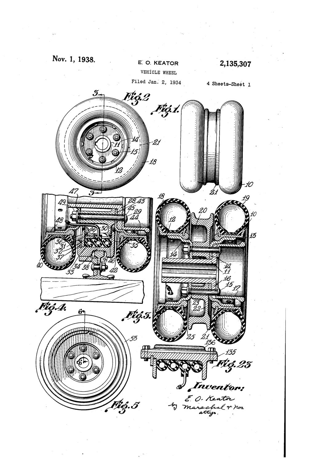
5 Patented Nov. 1, ,13,7 O U UNITED STATES PATENT OFFICE 2,13,7 VEHICLE WHEEL Edward O. Keator, Dayton, Ohio Application January 2, 1934, Serial No Claims. (C ) This invention relates to motor vehicles and the like. One object of the invention is the provision of a motor vehicle having wheels which are adapted for operation on rails and also adapted for oper ation on a pavement or road. Another object of the invention is the provision of a motor vehicle wheel having a common hub supporting an inflatable rubber surfaced tire adapted for operation on a pavement and also a metal tire or tractive member adapted for oper ation on a rail or on the ground. Another object of the invention is the provision of a motor vehicle wheel of the character men tioned, in which resilient means is provided be tween a wheel felly and the metal tire for cush ioning the shocks encountered in operation on rails or on the ground. - Another object of the invention is the provision of a truck or the like having dual rubber tired wheels, a flanged metal tire adapted for operation on a rail being provided between the rubber tires and serving to prevent stones from jamming be tween the rubber tires while the truck is in oper ation on a rough road. - Another object of the invention is the provision of a truck having wheels adapted to be steered which can be locked against steering movement, the wheels being equipped with tires adapted for operation on a pavement or road and also having metal tires adapted for operation on rails. Another object is the provision of a truck hav ing differentially driven rear wheels which are adapted for operation on rails, the wheels being adapted for positive driving engagement with the rails by means of gear means engaging racks pro vided Other on objects the rails. and advantages will be apparent from the following description, the appended claims and the accompanying drawings, in which-. Fig. 1 is a front elevation of a wheel embodying the present invention; Fig. 2 is a side view of the wheel; Fig. 3 is a vertical central section on the line 3-3 of Fig. 2; Fig. 4 is a sectional view showing form of construction; Fig. is a side view of the front wheel; Fig. 6 is a section on the line 6-6 of Fig. ; a modified Fig. 7 is a sectional view on the line 7-7 of Fig. 6; Fig. 8 is a vertical sectional view taken vertical ly through the steel tire of a wheel of a modified form of construction; Fig. 9 shows a further modification of the in vention; Fig. 10 shows one form of resilient means for the steel tire; Fig. 11 is section on the line ill-ff of Fig. 10; Fig. 12 is a side elevation of a truck embodying the invention and showing the manner of its application; Fig. 13 is a front elevation of the front of the truck in operation on the rails; wheels Fig. 14 is a rear elevation of the rear wheels of the truck; Fig. 1 is a detailed top plan view of the steering lock-out; Fig. 16 is a sectional view on the line 6-6 of Fig. 1;. Fig. 17 is a fragmentary side elevation show ing a wheel construction embodying gear teeth. adapted for engagement with a rack attached to the track; Fig. 18 is a fragmentary sectional view of sam on line 8, -8; - Fig. 19 is a fragmentary elevation of another modification of the invention in which a metal tire extension is adapted as an earth roller or tamper; -. Fig. is a fragmentary sectional view on line -; Fig. 21 is a side elevation of the magnetic brake attached to the vehicle in Fig. 12; - Fig. 22 is a sectional view of the magnetic brake; and. Fig. 23 is a fragmentary section of a metal tire with cleats on the circumference for use on soft ground. In accordance with the present invention trucks or motor vehicles are so constructed as to operate on a pavement or highway, Or on rails such as the standard railway tracks or the like, using either the highway or the rails either constantly or intermittently. For this purpose the wheels of the vehicle are provided with pneumatic tires adapted for operation on a pavement and are also provided with steel tires shaped and spaced to fit the rails of railroad tracks or the like and to operate thereon. As the essential parts of the wheels of the vehicle are detachably mounted on an axle part, the wheels may be easily and readily adapted for other purposes such as tamping, roll ing, etc. Each of the wheels of the vehicle, in accordance with the present invention, may have a single pneumatic tire or dual pneumatic tires. How ever, it is preferred that the front wheels should each have a single pneumatic tire While the rear 3 4 0

6 O 7 2 wheels are of the dual type. The two rear wheels 0, as shown in Figs. 1, 2 and 3, are each similar in construction, having a hub suitably keyed Or splined for attachment to the driving axle of any ordinary motor truck or vehicle construction. On the hub i? are detachably supported the two tire rims 2 and 3, each of which has an exten sion plate f4 through which the attaching bolts extend. The attaching bolts also pass. through holes provided in the plate portion 6 of the hub and through a suitable brake drum section f7. The usual retaining nut, not shown, is provided on the end of the axle to hold the wheel hub in position. The holding nuts of the bolts f are readily removable so that either one or both of the pneumatic tires can be removed and replaced on the wheel hub. ) Each of the rims 2 and 3 is provided with a pneumatic or inflatable tire, the two tires 8 and f each having a rubber tread adapted for operation on a road or pavement. Between the tires 8 and 9 is a metal rail engaging tire, having a flange 2 for cooperation with the side of the rail. As shown in Figs. 1 and 3 a flagge 2 is provided adjacent each end of the steel tire 2). The tire is supported by a plate member 22 on which are bosses 23 having holes through which the attachment bolts extend. The bosses 23 space the rim extension plates 4 apart a suitable distance so that there is some : clearance space as indicated at 2 between the ends of the steel-tire and the sides of the inflata ble tires in order that stones or rocks will not pass between the steel tire and the inflatable tires. The space 2, however, permits the lateral expansion of the pneumatic tires when the load of the truck is assumed, without destructive rub bing against the sides of the steel tire. As shown in Fig. 4, the steel rail engaging tire of a rear wheel may be yieldingly connected to the hub so that the usual shocks encountered by a vehicle operating on tracks are effectively absorbed. In this form of construction the hub 2 is securely attached to the inner portions 29 of the rail engaging member, preferably in a readily detachable manner, as shown. The pe ripheral portions of the member 29 provide a wheel felly 3D having an outer surface 3 f which is conically tapered. Fitting on the conical sur face f is the inner conical surface of an annular wedge ring 32 which is split at one portion so that it can expand and contract. Surrounding the wedge 32 is an inflatable tire or yielding rubber cushion 88, the cushion 33 substantially filling the space between the outer cylindrical wall of the wedge and the inner wall of the rail engaging tire 4, one side of which extends inwardly as shown at 3 alongside the side portion of the inner wheel portion 29. The other side of the rail engaging tire is formed of the removable end plate which is retained by a split holding ring 7 seating in an annular notch in an end portion of the steel tire. As shown in this construction, the two pneu matic tire rims are provided at some distance from the ends of the steel tire so that there is a Comparatively wide spacing between the two pneumatic tires and 4, leaving a suitable space. 42 between each pneumatic tire and the rail engaging tire to prevent destructive rubbing of the pneumatic tires on the steel tire. The spacing provided between the pneumatic tires, and the substantial closure for this spacing which is afforded by the steel tire prevents rocks 2,18,807 A. or the like from wedging between the pneumatic tires and thus injuring their casings. The various parts of the wheel shown in Fig. 4 may be assembled by first applying the plate extension 43 of the rim 44 together with the brake drum section to the fastening bolts 4 after which the felly of the tire engaging wheel is assembled. The steel tire 34 is placed so that its end 3 is adjacent the side of the wheel felly, suitable packing material 46 being employed in an annular slot or notch in the side portion 29. The cushion 33, which is preferably a single long tube closed at both ends, is then laid in the steel tire in several coils or turns, with the stem or valve portion applied to a small slot extend ing radially in the wheel felly. The annular Wedge or expansion ring 32, which is also slotted to re-receive the valve stem, is then moved in axially thus compressing the cushion 33 out Wardly and reducing the radial distance occupied by the cushion between the wheel felly and the inside diameter of the tire 34. The retaining plate 36 is then moved in place, with packing 46 3pplied between it and the outer side of the wheel felly, and the expansible split holding ring 37 is then expanded into the notch in the steel tire. The plate or disk 47 of the pneumatic tire rim 48 is then moved into position and the nuts 49 then tightened. The various parts may be read ily disassembled by carrying out the above pro cedure but in a reverse order. In the form of construction which has been de Scribed it will be apparent that a considerable amount of yielding movement is permitted be tween the steel tire and the hub, thus cushioning 3 the shocks encountered while the vehicle is op erating on tracks, but the various parts are so arranged that axial or endwise movement of one part of the wheel with respect to another is pre vented. The use of long pneumatic or solid rub ber cushion wound in several turns within the steel tire permits the effective utilization of the comparatively long but shallow space afforded in a tire of comparatively small diameter. The front wheels of the truck as well as the 4 rear wheels may be so constructed that the steel rail engaging tire is supported yieldingly on the hub. As shown in Figs. and 6 in which a front wheel of the truck is illustrated, each comprises a hub to which is firmly connected in a de tachable manner a rim 2 for the pneumatic tire 3. At one side of the pneumatic tire is the rail engaging metal tire 4 having a suitable out wardly extending flange for cooperation with the side of the rail. The tire 4 is supported yield ingly on its hub portion 6 by means of a pneu matic or solid rubber cushion 7 which may be laid in turns against the inner surface if the tire 4. An annular split spacing or shim ring 8 is preferably applied to the inside portions of the cushion 7, and a tapered split wedge 9, having a conical surface engaging a correspnndingly conical surface on the outside of the supporting felly 60 is forced axially in a right-hand direc tion to expand the Spacing ring 8. The spacing ion as the wedge is applied. The wedge and spac ing ring as well as he cushion are retained by the end disk or plate 6?, which is held in place by the expansible retaining ring 62. The inside surfaces of the steel tirs, 34 and 4, as shown in Fig. 7, are not smooth cylinders but on the contrary are somewhat corrugated or roughened as indicated at 64, and the split ring - ring prevents the Wedge from injuring the cush or sleeve 8 is also similarly formed with axially

7 O 2 2,13,807 extending corrugations so as to prevent any Sub stantial relative turning movement of the Wheel felly with respect to the steel tire and serve a de quately to transmit the driving force from the wheel hub to the steel tire. Cooperating projec tions and depressions 66 are also provided be tween the wedge ring 9 and the spacing ring and wheel felly to prevent relative turning movements of these parts during operation. Fig. 8 shows a modified form of wheel con struction in which the steel rail engaging tire 6 which is provided along side the pneumatic tire 66 is yieldingly supported by a Solid rubber cush ion designated generally 67. In this form of construction there is a toothed Or Corrugated annular rubber cushion member 68 cemented or vulcanized to an outer steel ring 69, both of these parts being split at one point to provide for con traction and expansion in order to facilitate as sembly within the rail engaging tire 6. Pref crably the steel surface portion 69 extends bc yond the end rubber teeth 69' as shown at 2 for cooperation with an extension lug. 3 pro vided on the inside surface of the steel tire for effectively transmitting the drive from the cush ion to the tire. Fitting in the depressions pro vided by the various teeth of the cushion mem ber 68 are the toothed projections of a second or inner rubber cushion member 74 which is se cured to an inner steel ring 7, these parts be ing also split at one end. The two rubber cushion members can be compressed by drawing their - Split ends together and can then be applied With in the tire 6. A tapered split wedge 76 having a notch 77 cooperating with a lug on the steel surface 7 and having a projection 8 cooperat ing with a notch on the wheel felly 79, is then forced in axially to expand the cushion inel bers firmly against the inside cylindrical Sur face of the tire, compressing the rubber teeth So that these teeth will not move apart at the upper portion of the wheel when a load is applied to the wheel. It will be understood that the various parts will be held in their assembled relationship in the same manner as in the forms of construction already described. The use of the rubber teeth permits relative cushioning movement in a radial direction without produc ing rubbing or wear on the cushion, the teeth affording substantial vertical movement of the Wheel hub with respect to the tire 6 at the Sides of the wheel as Well as at the top and bottom. Figs., 10 and 11 show another modification of the invention utilizing a solid rubber cushion between the wheel felly and the steel rail engag ing tire, the rubber cushion 80 having an outer metal surface 8 adapted to fit in the steel tire and having an inner metal surface 82, preferably all assembled together as a unit, for cooperation with the split wedge. In the wheel construction shown in Fig. 9 the metal rail engaging tire 8 is supported yielding ly on the wheel felly 86 by means of corrugated metal springs 87 and 88. The inner points of contact of the Spring 8 bear against a split wedge 89, spring 87 having a projection 90 which cooperates with a retaining slot or notch in the wheel felly. The outer Spring 88 has a projection 9 fitting in a notch provided in the rim 8. Thus there is an effective driving connection be tween the felly 86 and the steel tire through the Spring, the Spring affording resilient or yielding mounting of the tire so as to smooth out the shocks that would otherwise be produced described on an automobile or motor driven truck permits the vehicle to operate on the rails 92 of a railway track or the like, see Figs. 13, 14. and 1, while permitting Operation of the vehicle along a pavement or rough roadway. The rail en gaging tires of the truck may be so spaced apart as to Cooperate With existing, railways or with Special rails installed for grading operations or, the like. The figures of the drawing just re ferred to Show how the invention may be uti lized for grading purposes. The truck 94 may be driven by an internal combustion engine pro vided within the hood, 9, the power being. Sup- 3 plied through the usual differential drive, to the two rear wheels. These wheels may be run along the tracks 92 in transporting the load from one point to a disposal point. Fig. 12 shows, how the truck load may be dumped at a disposal point, the rear wheels of the truck being backed entirely off the track end and running on their pneumatic cushions beyond the ends of the track So that the load can be disposed at a desired point beyond the tracks. After disposing of the truck load, the truck may be mounted again on the tracks and then driven on the tracks in rough country until a pavement or roadway is reached. If the tracks are continued at the side of the road the truck may remain on the tracks, or if desired the truck may be driven off of the tracks and continue on the roadway as Occasion may require. To facilitate the operation of mounting the truck on tracks, and driving off of the tracks, at certain intervals the Space between the rails and Some little distance outside the rails may be filled in with soil or rock to a suitable height so that the pneumatic tires can assume the load of the truck and raise the rail engaging tires from the rails so that the truck can be readily driven Onto or off of the rails, or if desired suitable frogs and switches can be used at desired points to provide a means of readily getting to and from the track, and from one track to another. When the vehicle is operated on tracks it is desired that the front steerable wheels of the truck should be locked for straight ahead move ment. To accomplish this ears 96 may be pro vided on One of the front wheels, these ears hav ing holes aligned veltically with a hole passing through the front axle 97. A padlocked pin 98 extends through the holes in the ears and in the axle while the truck is operating on the rails, this pin being readily removable to release the Wheels so that the vehicle can be steered on the highway. Inasmuch as both wheels are tied to gether by the steering crossbar 99 the pin 98 serves to lock both front wheels against steering movement that could otherwise be imparted to the steering yoke 00. Figs. 13, 1 and 16 show a locking means that can be used in conjunction with or in place of the removable pin 98. The front axle 97 is pro vided with plates ff0 and in which is a slid ably mounted locking bolt 2. The locking bolt passes through a slot 3 in the cross bar 99 and projects into a notch 4 in the front axle. The locking bolt may be withdrawn by a rod op erated from the driver's position in the truck to release this bolt from the notch in the front axle and from the slot in the crossbar 99 thus afford ing endwise movement of the bar 99 which is controlled from the driver's seat by the usual steering wheel. However, when the bolt 2 is in the position shown in Figs. 1 and 16 all end The use of a wheel of the character herein wise movement of the steering tie bar 99 is pre- 7 O

8 O vented and the wheels are held in straight ahead position. It will be apparent that the rail engaging tires of the Wheels, which are made of Smaller diam eter than the tread diameter of the pneumatic tires, are effective in case of a puncture of a pneumatic tire in preventing serious injury or damage to the pneumatic tire, or upsetting, as the load is assumed temporarily in such a con tingency by the rail engaging tire. The rail engaging tire is also effective in preventing rocks or other damaging pieces from wedging between the two casings of a dual tire wheel, and is also effective in assuming and distributing the load when the vehicle is operating on extremely soft ground into which the pneumatic casing may be forced to an unusual distance. In Carrying out grading operations it is fre quently desirable to run a track at a compara tively steep grade, and to give an adequate trac tive drive, when the truck is running on rails up or down such an incline, a construction such as is shown in Figs. 17 and 18 and also in Fig. 12 may be employed. Referring more particularly to Figs. 17 and 18, the wheel hub 2.0 may be provided with the brake drum 2 and the flanged member 22. An angle member 23 is riveted to the flanged member 22, and serves as a support for the pneumatic tire rim 124, which is riveted in place thereon, and also as a Support for the detachably connected steel wheel 2. A pneumatic tire 26 is provided on rim 24. In this construction the members 2, 22, 23 and f24 are rolled steel parts which are cheaply and readily made and assembled together. The steel wheel or tire 2 is provided with a gear 27 which engages a rack f28 firmly secured at one side of the supporting rail 29, such gear and rack being duplicated at each side of the track. The pitch circle of the gear is preferably made to correspond in size to the diameter of the rail engaging surface of the steel wheel 2. Inas much as the two rear wheels are driven by the engine through the usual kind of a differential driving connection it will be apparent that with the two rear Wheels in positive driving engage ment with the tracks, a steep grade can readily be maneuvered, and the tracks may be curved, if desired, without detracting from the positive drive engagement of the wheels. This however WOuld not be the case if the two rear wheels are both geared to the track and mounted on a common driving wheel in accordance With the usual construction of rail vehicles. The metal tire 2 may be readily disconnected from the angle member 23, and may be replaced Or augmented by a second pneumatic tire and tire rim, if desired, or it may be replaced by another form of ground engaging member such as the "sheep's foot' tamper shown in Figs. 19 and. This tamper is provided with a number of tamping feet 3 mounted on a common cylindri cal ground engaging surface 32 which may be constructed as an extended tire member suitably fastened to the disk portion 33 by means of which it is readily. bolted to the wheel member or 23. Such a wheel or other earth rolling or trac tive wheel equipment may be readily applied to the truck to equip it for tamping, rolling or grad ing purposes, or for increased tractive effect over Soft Or. Slippery ground. A farmer can therefore readily adapt his truck to travel on rails, or to: travel on pavement, and when it becomes neces sary for him to use his truck as a tractor, for example, or as a tamper for earth rolling appa 2,13,807 ratus, he can remove the pneumatic tires and equip his truck with a cylindrical ground engaging tiremember or with a sheep's foot tamper or other desired form of wheel. Fig. 23 shows one form of wheel member which a farmer may use for giv ing increased tractive effect. In this case, the rail. engaging metal tire f3 corresponds in construc tion to the tire 4 of Fig. 6, except that there is no flange. This cylindrical tire member 3 may be used for rolling purposes, or if the truck is to be used as a tractor or for pulling effect, the detachably mounted cleats 36 may be bolted on the rim of the tire, the cleats being added in any desired number and spacing arrangement around the periphery. Figs. 21 and 22 show the magnetic pneumatic brake which is designated generally by the refer ence numeral in Fig. 12. Such a brake is provided on each side of the vehicle chassis and provides a braking effect very greatly exceeding that which is obtainable by braking the wheels of a metal rail engaging tire. Compressed air is sup plied when desired through a conduit 4 to a movable cylinder 42. The upper end of the cyl inder is closed by a fixed disk 43 while the lower end of the cylinder is secured to a magnet 44. When air is supplied to the cylinder the magnet is forced down into engagement with the rail 92, and as the magnet is moved down current is sup plied to the magnet winding through wires 4 causing the magnet to exert a high braking effect as the magnet drags along the rails. Such an arrangement is particularly desirable where the truck is being maneuvered up and down steep grades, since the coefficient of friction of a steel wheel and a steel rail is quite small and only comparatively Small braking effect is obtainable, in the usual arrangement. While the forms of apparatus herein described Constitute preferred embodiments of the inven tion, it is to be understood that the invention is not limited to these precise forms of apparatus, and that changes may be made therein without departing from the scope of the invention which is defined in the appended claims. 'What is claimed is: 1. A vehicle wheel comprising a hub, a wheel felly supported on said hub, a flanged metal tire adapted for operation on a rail and supported by Said felly for radial movement thereon, a double ended inflatable tube in helical form between said felly and said metal tire for yieldingly restrain ing relative radial movement of the tire and felly, and a tapering split wedge having a frusto-coni cal surface and provided between said tube and Said wheel felly and movable axially to compress Said tube against said tire. 2. A vehicle wheel comprising a hub, a wheel felly supported on said hub, a metal tire support ed by said felly for radial movement thereon, resilient means between said felly and metal tire, means for retaining said metal tire against axial movement on said felly, a separate expansible metal ring shim in engagement at one side there of With Said resilient means and disposed radially of Said resilient means, and an annular wedge provided within Said metal tire and engaging the other side of said ring shim and movable axially thereof to compress said resilient means. 3. A vehicle wheel comprising a hub, a wheel felly Supported on said hub, a metal tire support ed by Said felly for radial movement thereon, resilient means between said felly and metal tire, means for retaining said metal tire against axial movement on Said felly, a separate expansible r O
9 0. metal ring shim in engagement at One side there of with said resilient means and disposed radially of said resilient means, and an annular Wedge provided within said metal tire and engaging the other side of said ring shim and movable axially there f to compress said resilient means, Said metal tire having an irregular internal Surface adapted for gripping effect on said resilient eas. 4. A vehicle wheel comprising a hub, a wheel felly supported on said hub, a metal tire sup ported by said felly for radial movement thereon, resilient means between said felly and metal tire 2,13,807 comprising a double ended inflatable tube in heli cal form on said felly for yieldingly restraining, relative radial movement of the tire and felly, means for retaining said metal tire against axial movement on said felly, an expansible metal ring shim in engagement at one side thereof with said resilient means and disposed radially thereof, and an annuiar wedge provided within said metal tire and engaging the other side of said ring shim and movable axially thereof to compress said resilient 10 63S EDWARD O. KEATOR.
?zzzzzzzzzzzzzzzzzzzzzzzzzzzzzzzzzzzzzzz -! zzzzzzzzz,zzzzzzzzz. sssss?sssssss,! PATENTED JULY 21, PNEU MATIC SUSPENSION MEANS, J. H.
 J. H. CLARK, PNEU MATIC SUSPENSION MEANS, APPLICATION FILED JUNE 24 1907. PATENTED JULY 21, 1908. sssss?sssssss,! S?zzzzzzzzzzzzzZZZZZZZZZZZZZZZZZZZZZZZZZZ -! SN 22 222 zzzzzzzzz,zzzzzzzzz INVENTOR ZVetezrzes...
/6/6 64. Oct. 14, , Vi: 2,613,753. Wa?ter C. Stueóira
 Oct. 14, 1952 W. C. STUEBING, JR MOTORIZED DRIVE WHEEL ASSEMBLY FOR LIFT TKUCKS. OR THE LIKE Filed Sept. 26, 1946 3. Sheets-Sheet 1 NVENTOR Wa?ter C. Stueóira BY 64. /6/6 NE, Vi: Oct. 14, 1952 W. C. STUEBING,
United States Patent (19)
") United States Patent (19) Hodgetts (54) (75) 73 (1) ) (51) (5) (58) (56) NTERNALLY MUNTED DRIVE MECHANISM FR A BELT-WINDING DRUM Inventor: Assignee: Appl. No.: Filed: Graham L. Hodgetts, Mars, Pa. Rolflor
United States Patent (19) Hodgetts (54) (75) 73 (1) ) (51) (5) (58) (56) NTERNALLY MUNTED DRIVE MECHANISM FR A BELT-WINDING DRUM Inventor: Assignee: Appl. No.: Filed: Graham L. Hodgetts, Mars, Pa. Rolflor
Feb. 14, 1967 R. B. WENGER 3,304,094 CLIMBING WHEEL CHAIR A/C. Z. 5 is INVENTOR. a/caezo as a 7/gate, 57 d. 2. XO aoz. 1277aatavays.
 Feb. 14, 1967 R. B. WENGER CLIMBING WHEEL CHAIR Filed Dec. 22, 1964 3. Sheets-Sheet A/C. Z. is INVENTOR. a/caezo as a 7/gate, BY 7 d. 2. XO-4-2. 32427 aoz 1277aatavays. Feb. 14, 1967 R. B. WENGER CLIMBING
2,407,010 ADAPTER HEAD FOR WELLS. Filed Aug. 8, Sheets-Sheet. Lester C. Hudson
 Sept. 3, 1946. L. C. HUDSON 2,407,010 ADAPTER HEAD FOR WELLS Filed Aug. 8, 1945 2 Sheets-Sheet Lester C. Hudson Sept. 3, 1946. 2 407,010 L. C. HUDSON ADAPTER HEAD FOR WELLS Filled Aug. 8, 1945 2. Sheets-Sheet
- F WEN N 42. Czz724,2 Zz-ssa 7ce. E. BY. Oct. 21, 1958 C. F. DASSANCE 2,856,797 3A 42. Filed June 1, 1953 INVENTOR.
 Oct. 21, 1958 C. F. DASSANCE WARIABLE SPEED GEAREO PULEY 2 Sheets-Sheet Filed June 1, 1953 2. WEN N 42 3A 42 INVENTOR. Czz724,2 Zz-ssa 7ce. E. BY - F - 4.2.2 Oct. 21, 1958 C. F. DASSANCE WARIABLE SPEED
(12) Patent Application Publication (10) Pub. No.: US 2004/ A1
 Patent Application Publication (10) Pub. No.: US 2004/ A1") US 2004.00431 O2A1 (19) United States (12) Patent Application Publication (10) Pub. No.: US 2004/0043102 A1 H0 et al. (43) Pub. Date: Mar. 4, 2004 (54) ALIGNMENT COLLAR FOR A NOZZLE (52) U.S. Cl.... 425/567
US 2004.00431 O2A1 (19) United States (12) Patent Application Publication (10) Pub. No.: US 2004/0043102 A1 H0 et al. (43) Pub. Date: Mar. 4, 2004 (54) ALIGNMENT COLLAR FOR A NOZZLE (52) U.S. Cl.... 425/567
F, L, BARBER & C. S. WAT 0 N, CAR TRUCK, APPLICATION FILED APR. 28, 9. Patented June 12, , SHEETS-SHEET 2. ssna
 1229,398. F, L, BARBER & C. S. WAT 0 N, CAR TRUCK, APPLICATION FILED APR. 28, 9. Patented June 12, 1917. 2. SHEETS-SHEET 2. ssna it worris FEFFRS (c. soro ir G. vwasi trw«. * OM. 2 C I.5 35 UNITED STATES
UNITED STATES PATENT OFFICE
 UNITED STATES PATENT OFFICE FRANKLIN A. ERRINGTON, OF NEW YORK, N. Y. PRO PE ER REVERS E G EAR IO 3O 35 40 45 SPECIFICATION forming part of Letters Patent No. 644,508, dated February 27, 1900. Application
United States Patent (19) Koitabashi
 Koitabashi") United States Patent (19) Koitabashi 54 75 (73) 1 (51) (5) (58 56) ELECTROMAGNETIC CLUTCH WITH AN IMPROVED MAGNETC ROTATABLE MEMBER Inventor: Takatoshi Koitabashi, Annaka, Japan Assignee: Sanden Corporation,
United States Patent (19) Koitabashi 54 75 (73) 1 (51) (5) (58 56) ELECTROMAGNETIC CLUTCH WITH AN IMPROVED MAGNETC ROTATABLE MEMBER Inventor: Takatoshi Koitabashi, Annaka, Japan Assignee: Sanden Corporation,
Dec. 3, G. H. LELAND 1,737,595 ELECTRIC MOTOR W/a Av/2Ap. 2-2, 3 3 6AOAGAA. l. E/A/VD. 4772A/VAy
 Dec. 3, 1929. G. H. LELAND 1,737,595 ELECTRIC MOTOR. Filed Sept. 20, 1926 2 Sheets-Sheet - - - - - - 9. -- W/a Av/2Ap. 3 3 6AOAGAA. l. E/A/VD. 2-2, 4772A/VAy Dec. 3, 1929. G. H. LELAND 1,737,595 ELECTRIC
United States Patent 19 Nitschke
 United States Patent 19 Nitschke (54) SPRING END CAP FOR CONVEYORROLLS 76 Inventor: Norman C. Nitschke, 9102 Buck Rd., Perrysburg, Ohio 43551 21 Appl. No.: 803,491 22 Filed: Jun. 6, 1977 5ll Int. Cl...
& 9. Š. Aerary 4. Morazzzzzok. May 19, : 1,538,208. INVENTORS INTERNAL COMBUSTION MOTOR. atz Aazzzz c1. A1arclaezzf H. A. NORDWICK E. A.
 May 19, 1925. :. H. A. NORDWICK E. A. INTERNAL COMBUSTION MOTOR Filed Oct, l9, 1923 2. Sheets-Sheet. & 9. Š W S A. SSS S S R Sr. SS SS INVENTORS Aerary 4. Morazzzzzok atz Aazzzz c1. A1arclaezzf. ar a ATTORNEY
Feb. 25, 1958 B. CAMETTI ET AL 2,824,983 ELECTRIC MOTOR COOLING
 Feb. 25, 1958 B. CAMETTI ET AL 2,824,983 ELECTRIC MOTOR COOLING Filed Nov. 2, 1954 2 Sheets-Sheet l Fig. 3. NVENTOR Benjamin Cametti 8 William M. Wepfer. -1,3-al ATTORNEY Feb. 25, 1958 B. CAMETTI ETAL
April 5, G, E, SWANSON 2,113,007 CYLINDER LOCK. NS: S.S.S.S.S Né EEE SS W. a. <SNSSSSSSSS/fde. is E( 4 NN. p7 NSN NNNN N&zo 76 v7 /6 2/23 / NS
 April, 1938. G, E, SWANSON CYLINDER LOCK Filed May 17, 1937 2. Sheets-Sheet 1 SNNNN ÉSEŠEŠ V 443 SY NS: S.S.S.S.S Né EEE SS W. a.
HHRH. United States Patent (19) Lissaman et al. (11) Patent Number: 5,082,079 (45) Date of Patent: Jan. 21, 1992 (51) (54) (75) (73)
 Lissaman et al. (11) Patent Number: 5,082,079 (45) Date of Patent: Jan. 21, 1992 (51) (54) (75) (73)") United States Patent (19) Lissaman et al. HHRH US00082079A (11) Patent Number:,082,079 (4) Date of Patent: Jan. 21, 1992 (4) (7) (73) 21) 22 (1) (2) (8) PASSIVELY STABLE HOVERNG SYSTEM Inventors: Assignee:
United States Patent (19) Lissaman et al. HHRH US00082079A (11) Patent Number:,082,079 (4) Date of Patent: Jan. 21, 1992 (4) (7) (73) 21) 22 (1) (2) (8) PASSIVELY STABLE HOVERNG SYSTEM Inventors: Assignee:
United States Patent (19) 11 Patent Number: 4,465,446. Nemit, Jr. et al. (45) Date of Patent: Aug. 14, 1984
 11 Patent Number: 4,465,446. Nemit, Jr. et al. (45) Date of Patent: Aug. 14, 1984") United States Patent (19) 11 Patent Number: 4,4,446 Nemit, Jr. et al. () Date of Patent: Aug. 14, 1984 (54) RADIAL AND THRUST BEARING 3,4,313 7/1969 Lohneis a on - a a a a 8/236 MOUNTINGS PROVIDING INDEPENDENT
United States Patent (19) 11 Patent Number: 4,4,446 Nemit, Jr. et al. () Date of Patent: Aug. 14, 1984 (54) RADIAL AND THRUST BEARING 3,4,313 7/1969 Lohneis a on - a a a a 8/236 MOUNTINGS PROVIDING INDEPENDENT
April 24, 1951 LE ROY S. schell, JR 2,550,500
 April 24, 1951 LE ROY S. schell, JR LOW YOKE TRANSFORMER CORE Filed Sept. 24, l943 3. Sheets-Sheet Inventor: LeRouy S. Schell, v Jr., bu-all s 73Mass 29 His Attorneu. April 24, 1951 Filed Sept. 24, 1948
(12) Patent Application Publication (10) Pub. No.: US 2008/ A1
 Patent Application Publication (10) Pub. No.: US 2008/ A1") (19) United States US 20080000052A1 (12) Patent Application Publication (10) Pub. No.: US 2008/0000052 A1 Hong et al. (43) Pub. Date: Jan. 3, 2008 (54) REFRIGERATOR (75) Inventors: Dae Jin Hong, Jangseong-gun
(19) United States US 20080000052A1 (12) Patent Application Publication (10) Pub. No.: US 2008/0000052 A1 Hong et al. (43) Pub. Date: Jan. 3, 2008 (54) REFRIGERATOR (75) Inventors: Dae Jin Hong, Jangseong-gun
issue? - $4.4% Vils/lor (Zigsten July 9, 1957 Nils-Olof OLESTEN 2,798,743 FLEXIBLE COUPLING DEVICE FOR CONNECTING JET-ENGINE-POWERED
 July 9, 1957 Nils-Olof OLESTEN FLEXIBLE COUPLING DEVICE FOR CONNECTING JET-ENGINE-POWERED AIRCRAFT TO GROUND MOUNTED SILENCERS Filed March 23, 1955 3 Sheets-Sheet l $4.4% Vils/lor (Zigsten issue? - : July
Jan. 14, ,421,236. Filed June 22, E, U, MOYER ATTORNEYS LINKAGE FOR AN EJECTOR TYPE BUCKET, LOADER
 Jan. 14, 1969 Filed June 22, E, U, MOYER LINKAGE FOR AN EJECTOR TYPE BUCKET, LOADER ATTORNEYS Jan. 14, 1969 E. U. MOYER LINKAGE FOR AN EJECTOR TYPE BUCKET, LOADER Filed June 22, 1967 Sheet a of 2. INVENTOR
April 2, 1968 A. L. NASVYTIs 3,375,739 CONICAL, PLANETARY FRICTION GEAR DRIVE Filed Feb. 17, Sheets-Sheet l N. N S
 April 2, 1968 A. L. NASVYTIs CONICAL, PLANETARY FRICTION GEAR DRIVE Filed Feb. 17, 1966 3 Sheets-Sheet l st SS N. N S A. N S INVENTOR. 167/raas Z. Maszy/7s -3% 1%-1. 72e-este, "4e 71-16tz,ORNEYS April
EWSAN. United States Patent (19) 4,696,524. Cloyd. Sep. 29, ROBOT ARM COUPLING APPARATUS Inventor: Assignees:
 4,696,524. Cloyd. Sep. 29, ROBOT ARM COUPLING APPARATUS Inventor: Assignees:") United States Patent (19) Cloyd (54) (75) (73) 21) 22 51) (52) (58) (56) ROBOT ARM COUPLING APPARATUS Inventor: Assignees: William C. Cloyd, Lexington, Ky. Custom Tool & Mfg. Co.; Automation Development
United States Patent (19) Cloyd (54) (75) (73) 21) 22 51) (52) (58) (56) ROBOT ARM COUPLING APPARATUS Inventor: Assignees: William C. Cloyd, Lexington, Ky. Custom Tool & Mfg. Co.; Automation Development
uranayasa NNN (226er? Z /zcz-az77a 7-z Dec. 1, 1959 A. F., HICKMAN 2,915,306 RUBBER TORSION SPRING ZZZZZZZZA SSXSSSSSSSSSSS 50 \... "...
 Dec. 1, 1959 A. F., HICKMAN 2,915,306 RUBBER TORSION SPRING Filed June 24, 1955 2 Sheets-Sheet l NYaNNNNNNNaa %2 uranayasa NNN IX ZZZZZZZZA \........ "......: S SSXSSSSSSSSSSS 50 12 42 INVENTOR. (226er?
APPLICATION FLED JAN, 27, 1917, 1253,982, Patented Jan, 15, 1918,
 H, V, KRBY, FUSHNG MECHANISM, APPLICATION FLED JAN, 27, 1917, 1253,982, Patented Jan, 15, 1918, 2. SHEES-SHEET, H, V, KRBY, FUSHING MECHANISM, APPLICATION FLED JAN, 27, 1917, 253,982, Patented Jan. 15,
(12) Patent Application Publication (10) Pub. No.: US 2014/ A1
 Patent Application Publication (10) Pub. No.: US 2014/ A1") (19) United States US 20140299792A1 (12) Patent Application Publication (10) Pub. No.: US 2014/0299792 A1 Yee et al. (43) Pub. Date: Oct. 9, 2014 (54) SEALING ABOUT A QUARTZ TUBE (52) U.S. Cl. CPC... F2IV31/005
(19) United States US 20140299792A1 (12) Patent Application Publication (10) Pub. No.: US 2014/0299792 A1 Yee et al. (43) Pub. Date: Oct. 9, 2014 (54) SEALING ABOUT A QUARTZ TUBE (52) U.S. Cl. CPC... F2IV31/005
(12) Patent Application Publication (10) Pub. No.: US 2015/ A1
 Patent Application Publication (10) Pub. No.: US 2015/ A1") (19) United States US 2015 0084494A1 (12) Patent Application Publication (10) Pub. No.: US 2015/0084494 A1 Tonthat et al. (43) Pub. Date: Mar. 26, 2015 (54) SLIDING RACK-MOUNTABLE RAILS FOR H05K 5/02 (2006.01)
(19) United States US 2015 0084494A1 (12) Patent Application Publication (10) Pub. No.: US 2015/0084494 A1 Tonthat et al. (43) Pub. Date: Mar. 26, 2015 (54) SLIDING RACK-MOUNTABLE RAILS FOR H05K 5/02 (2006.01)
2,835,125 LATCHING MECHANISM. 3. Sheets-Sheet 2 NII N bel2. gy:jip 72UL. ali?i. 2%. s: 2. t. NU 2z, Z z? Azózzee/
 May, 1958 H. F. GEORGE LATCHING MECHANISM 3. Sheets-Sheet 2 2 NII-376 2N bel2 (3 Sl Ig gy:jip 72UL 2 707 ali?i 2 2%. s: 2. t NU 2z, Z.427 272 z? Azózzee/ May, 1958 H. F. GEORGE LATCHING MECHANISM Filed
(12) Patent Application Publication (10) Pub. No.: US 2003/ A1
 Patent Application Publication (10) Pub. No.: US 2003/ A1") US 2003O190837A1 (19) United States (12) Patent Application Publication (10) Pub. No.: US 2003/0190837 A1 W (43) Pub. Date: Oct. 9, 2003 (54) BATTERY HOLDER HAVING MEANS FOR (52) U.S. Cl.... 439/500 SECURELY
US 2003O190837A1 (19) United States (12) Patent Application Publication (10) Pub. No.: US 2003/0190837 A1 W (43) Pub. Date: Oct. 9, 2003 (54) BATTERY HOLDER HAVING MEANS FOR (52) U.S. Cl.... 439/500 SECURELY
June 6, ,987,128 W. KREG SOIL, DAMMING IMPLEMENT. Filed June ll, Sheets-Sheet. Werner Arieg INVENTOR. &&. ~~~~
 June 6, 1961 Filed June ll, 197 W. KREG SOIL, DAMMING IMPLEMENT 2 Sheets-Sheet ~~~~ Werner Arieg INVENTOR. &&. June 6, 1961 Filed June ill, 197 W. KREG SOIL, DAMMING IMPLEMENT 2 Sheets-Sheet 2 Werner Arieg
Aug. 10, ,595,232 W. S. HARLEY ELECTRIC SWITCH. HParié a. % - se. Zezezza77. Za2z/2a22 J/622ce/ 72/ ( clo-c-3 v (J.,
 Aug. 10, 1926. 1,595,232 W. S. HARLEY ELECTRIC SWITCH Filed April 13, 1922 2. Sheets-Sheet f t Fre ls HParié a % - se Sh Zezezza77 Za2z/2a22 J/622ce/ 72/ ( clo-c-3 v (J., Aug. 10, 1926. 1,595,232 W. S.
*2.4 crewat (totif. I realizo. all estalla-ze. June 2, M. J. POSTER 1,807,752 AUTOMOBILE TIRE INDICATOR OR GAUGE Filed April 8, 1930.
 June 2, 1931. M. J. PSTER 1,7,72 AUTMBILE TIRE INDICATR R GAUGE Filed April 8, 19 2 Sheets-Sheet 1 14 2SSSSSSSSs a2%%n 2 3. seases Élisé 2. 3 S 3 263 E 3aw 3 ES 3 e I realizo 2 all estalla-ze a slue Ig
No.sse,*****<<<<<<<<<<<<
 June 3, 1936. F. J. WOLFF MIXING WALWE Filed Dec. 9, N SY 1933,04,308. Sheets-Sheet l No.sse,*****
(12) Patent Application Publication (10) Pub. No.: US 2002/ A1
 Patent Application Publication (10) Pub. No.: US 2002/ A1") (19) United States US 2002O00861 OA1 (12) Patent Application Publication (10) Pub. No.: US 2002/0008610 A1 PetersOn (43) Pub. Date: Jan. 24, 2002 (54) KEY FOB WITH SLIDABLE COVER (75) Inventor: John Peterson,
(19) United States US 2002O00861 OA1 (12) Patent Application Publication (10) Pub. No.: US 2002/0008610 A1 PetersOn (43) Pub. Date: Jan. 24, 2002 (54) KEY FOB WITH SLIDABLE COVER (75) Inventor: John Peterson,
"(2.4% May 4, 1954 C. A. GUSTAFSON 2,677,202. Filed April 3, l95l AND EJECTOR OF EARTH-MOWING SCRAPERS 3. Sheets-Sheet CAR. A.
 May 4, 1954 C. A. GUSTAFSON 2,677,202 HYDRAULIC ACTUATOR FOR OPERATING THE APRON Filed April 3, l95l AND EJECTOR OF EARTH-MOWING SCRAPERS 3. Sheets-Sheet INVENTOR, CAR. A. G2/S7AASOM/ "(2.4%. 2.-- ATTORME,
March 17, 1964 N. E. MERRELL 3,125,164 RELEASABLE COUPLING DEVICE
 March 17, 1964 N. E. MERRELL 3,12,164 Filed Dec. 4, 1962 RELEASABLE COUPLING DEVICE 3. Sheets-Sheet l NORMAN E. INVENTOR. MERRELL e.s.a. N. (A ATTORNEY March 17, 1964 N. E., MERRELL 3,12,164 RELEASABLE
2,042,301. VALVE SEAT FOR AIR BLAST WALVES Filled May 3, Sheets-Sheet. By??????r /7
 May 26, 1936. G. FOX VALVE SEAT FOR AIR BLAST WALVES Filled May 3, 1934 2 Sheets-Sheet 11 -W + By??????r /7 May 26, 1936. G. FOX WALWE SEAT FOR AIR BLAST WALWES Filed May 3, 1934 %22&zzzzzzzzº2zzzzzzzzzzzzzzzzzzzzzzzzzzzzzzzzzzzzzzzzzzzzzzzzzzzzzzzzz
2,376,968. May 29, F. M. JONES TWO-CYCLE GAS ENGINE. 2 Sheets-Sheet li. Filed Dec. 26, 1942 FIG, vucinto FREDERICK M. JONES.
 May 29, 1945. F. M. JONES Filed Dec. 26, 1942 2 Sheets-Sheet li 7. FIG, 8??? ///?/ ( vucinto FREDERICK M. JONES ( Cltt May 29, 1945. F. M. JONES Filed Dec. 26, 1942 2. Sheets-Sheet 2 48 aa FG. 2 35 21
Aug. 18, H. C. H. WASH ET AL 2,051,116 POWER PRESS DRIVING MECHANISM. Zezezézy. 6.2%zz & WZ
 Aug. 18, 1936. H. C. H. WASH ET AL 2,051,116 Filed Jan. 22, 1934 2. Sheets-Sheet l Zezezézy. % 6.2%zz & WZ Aug. 18, 1936. H. C. H. WALSH ET AL Filed Jan. 22, 1934 2,051,116 2 Sheets-Sheet 2 62/64% WZ 64%,
Six R. Seizi. United States Patent 19 ZKK, 2.S. NSS NEG. Sayo et al. 11 4,150, Apr. 24, ELECTROMAGNETIC CLUTCH NS3NS
 United States Patent 19 Sayo et al. 54 ELECTROMAGNETIC CLUTCH 75 Inventors: Kosaku Sayo, Katsuta; Seijiro Tani, Naka; Atsushi Sugirauma, Hitachi, all of Japan 73) Assignee: Hitachi, Ltd., Japan 21 Appl.
(12) United States Patent
 United States Patent") USOO7534048B2 (12) United States Patent Holman (54) CENTER BEARING ASSEMBLY FOR ROTATABLY SUPPORTING ASHAFTAT VARYING ANGLES RELATIVE TO A SUPPORT SURFACE (75) Inventor: James L. Holman, Wauseon, OH (US)
USOO7534048B2 (12) United States Patent Holman (54) CENTER BEARING ASSEMBLY FOR ROTATABLY SUPPORTING ASHAFTAT VARYING ANGLES RELATIVE TO A SUPPORT SURFACE (75) Inventor: James L. Holman, Wauseon, OH (US)
(12) Patent Application Publication (10) Pub. No.: US 2005/ A1
 Patent Application Publication (10) Pub. No.: US 2005/ A1") (19) United States US 2005011 5350A1 (12) Patent Application Publication (10) Pub. No.: US 2005/0115350 A1 Ohashi et al. (43) Pub. Date: Jun. 2, 2005 (54) MOTOR WITH REDUCTION MECHANISM Sep. 2, 2004 (JP)...
(19) United States US 2005011 5350A1 (12) Patent Application Publication (10) Pub. No.: US 2005/0115350 A1 Ohashi et al. (43) Pub. Date: Jun. 2, 2005 (54) MOTOR WITH REDUCTION MECHANISM Sep. 2, 2004 (JP)...
Az Z 1.357,665. Azzee/2Z27. Patented Nov. 2, y 24-cee?, A-6. vy
 1.7,665. P. H. WATKNS, (UM SHEETING AND SCORING MACHINE, APPLICATION FILED MAY 28, 1920. Patented Nov. 2, 1920. 2 SHEETS-SHEET 1. Az Z B Azzee/2Z27 A 27/62//l/2éAz72s. y 24-cee?, A-6. vy-4----. P, H, WAT
(12) Patent Application Publication (10) Pub. No.: US 2007/ A1
 Patent Application Publication (10) Pub. No.: US 2007/ A1") US 20070257638A1 (19) United States (12) Patent Application Publication (10) Pub. No.: US 2007/0257638A1 Amend et al. (43) Pub. Date: Nov. 8, 2007 (54) TWIST LOCK BATTERY INTERFACE FOR (52) U.S. Cl....
US 20070257638A1 (19) United States (12) Patent Application Publication (10) Pub. No.: US 2007/0257638A1 Amend et al. (43) Pub. Date: Nov. 8, 2007 (54) TWIST LOCK BATTERY INTERFACE FOR (52) U.S. Cl....
(12) Patent Application Publication (10) Pub. No.: US 2014/ A1
 Patent Application Publication (10) Pub. No.: US 2014/ A1") (19) United States US 2014O124322A1 (12) Patent Application Publication (10) Pub. No.: US 2014/0124322 A1 Cimatti (43) Pub. Date: May 8, 2014 (54) NORMALLY CLOSED AUTOMOTIVE (52) U.S. Cl. CLUTCH WITH HYDRAULC
(19) United States US 2014O124322A1 (12) Patent Application Publication (10) Pub. No.: US 2014/0124322 A1 Cimatti (43) Pub. Date: May 8, 2014 (54) NORMALLY CLOSED AUTOMOTIVE (52) U.S. Cl. CLUTCH WITH HYDRAULC
United States Patent (19)
") United States Patent (19) Ryder 54 RUN FLAT DEVICE FOR TRES 75 Inventor: John Charles Ryder, Doylestown, Ohio 73 Assignee: The Firestone Tire & Rubber Company, Akron, Ohio 22 Filed: Apr. 3, 1970 (21) Appl.
United States Patent (19) Ryder 54 RUN FLAT DEVICE FOR TRES 75 Inventor: John Charles Ryder, Doylestown, Ohio 73 Assignee: The Firestone Tire & Rubber Company, Akron, Ohio 22 Filed: Apr. 3, 1970 (21) Appl.
Continuously Variable Transmission
 Continuously Variable Transmission TECHNICAL FIELD The present invention relates to a transmission, and more particularly, a continuously variable transmission capable of a continuous and constant variation
May 19, 1964 AT TORNEY 3,133,451. R. J. THOMAs MULTIPLE REDUCTION GEAR UNIT. Filed Dec. 28, 196l. 3. Sheets-Sheet 1 R CHARD J.
 May 19, 1964 Filed Dec. 28, 196l. R. J. THOMAs MULTIPLE REDUCTION GEAR UNIT 3. Sheets-Sheet 1 NVENTOR R CHARD J. TOMAS AT TORNEY May 19, 1964 Filed Dec. 28, 196 R. J. THOMAS MULTIPLE REDUCTION GEAR UNIT
(12) Patent Application Publication (10) Pub. No.: US 2007/ A1
 Patent Application Publication (10) Pub. No.: US 2007/ A1") (19) United States US 2007026 1863A1 (12) Patent Application Publication (10) Pub. No.: US 2007/0261863 A1 MACLEOD et al. (43) Pub. Date: Nov. 15, 2007 (54) SEALING SYSTEM (52) U.S. Cl.... 166/387: 166/202
(19) United States US 2007026 1863A1 (12) Patent Application Publication (10) Pub. No.: US 2007/0261863 A1 MACLEOD et al. (43) Pub. Date: Nov. 15, 2007 (54) SEALING SYSTEM (52) U.S. Cl.... 166/387: 166/202
W. Hope. 15 Claims, 5 Drawing Figs. (52) U.S. Cl , 5ll int. Cl... F16k 43100, F16k 5/14
 U.S. Cl , 5ll int. Cl... F16k 43100, F16k 5/14") United States Patent (72 inventor Clyde H. Chronister 4 Kings Row, Rte. 14, Houston, Tex. 77040 (2) Appl. No. 823,103 (22 Filed May 8, 1969 45 Patented Jan. 26, 197i. 54) GATE WALVE 15 Claims, 5 Drawing
United States Patent (72 inventor Clyde H. Chronister 4 Kings Row, Rte. 14, Houston, Tex. 77040 (2) Appl. No. 823,103 (22 Filed May 8, 1969 45 Patented Jan. 26, 197i. 54) GATE WALVE 15 Claims, 5 Drawing
United States Patent (19) Cronk et al.
 Cronk et al.") United States Patent (19) Cronk et al. (S4) LANDING GEAR FOR ULTRALIGHT AIRCRAFT 76) Inventors: David Cronk, 1069 Eucalyptus Ave., Vista, Calif. 92025; Lyle M. Byrum, 1471 Calle Redonda, Escondido, Calif.
United States Patent (19) Cronk et al. (S4) LANDING GEAR FOR ULTRALIGHT AIRCRAFT 76) Inventors: David Cronk, 1069 Eucalyptus Ave., Vista, Calif. 92025; Lyle M. Byrum, 1471 Calle Redonda, Escondido, Calif.
(12) Patent Application Publication (10) Pub. No.: US 2007/ A1
 Patent Application Publication (10) Pub. No.: US 2007/ A1") (19) United States (12) Patent Application Publication (10) Pub. No.: US 2007/0266837 A1 Nickels et al. US 20070266837A1 (43) Pub. Date: Nov. 22, 2007 (54) CLAMPASSEMBLY (76) Inventors: Richard C. Nickels,
(19) United States (12) Patent Application Publication (10) Pub. No.: US 2007/0266837 A1 Nickels et al. US 20070266837A1 (43) Pub. Date: Nov. 22, 2007 (54) CLAMPASSEMBLY (76) Inventors: Richard C. Nickels,
-10 III. United States Patent to. 39a. 39b. 21 Claims, 3 Drawing Sheets. Appl. No.: 643,492 Fied: May 6, 1996 Int. Cla.m.
 United States Patent to Lutzker III US005683166A 11 Patent Number: 5,683,166 45 Date of Patent: Nov. 4, 1997 54 (76 21 22) 51 52 (58) ELECTROLUMNESCENT WALLPLATE Inventor: Robert S. Lutzker, Woodstone
United States Patent (19) Muranishi
 Muranishi") United States Patent (19) Muranishi (54) DEVICE OF PREVENTING REVERSE TRANSMISSION OF MOTION IN A GEAR TRAIN 75) Inventor: Kenichi Muranishi, Ena, Japan 73) Assignee: Ricoh Watch Co., Ltd., Nagoya, Japan
United States Patent (19) Muranishi (54) DEVICE OF PREVENTING REVERSE TRANSMISSION OF MOTION IN A GEAR TRAIN 75) Inventor: Kenichi Muranishi, Ena, Japan 73) Assignee: Ricoh Watch Co., Ltd., Nagoya, Japan
United States Patent (19) Preusker
 Preusker") United States Patent (19) Preusker 11 Patent Number: (45) Date of Patent: 4,576,214 Mar. 18, 1986 (54) NON-SKID DEVICE, PARTICULARLY FOR PNEUMATICALLY THREED VEHICLE WHEELS USED ON CE AND SNOW 75) Inventor:
United States Patent (19) Preusker 11 Patent Number: (45) Date of Patent: 4,576,214 Mar. 18, 1986 (54) NON-SKID DEVICE, PARTICULARLY FOR PNEUMATICALLY THREED VEHICLE WHEELS USED ON CE AND SNOW 75) Inventor:
(12) Patent Application Publication (10) Pub. No.: US 2010/ A1. (51) Int. Cl. of the spool. 20e /2-20s Z2 2 X XX 7
 Patent Application Publication (10) Pub. No.: US 2010/ A1. (51) Int. Cl. of the spool. 20e /2-20s Z2 2 X XX 7") (19) United States (12) Patent Application Publication (10) Pub. No.: US 2010/0314564 A1 Hoeptner, III US 20100314564A1 (43) Pub. Date: Dec. 16, 2010 (54) APPARATUS WITH MOVABLE TIMING SLEEVE CONTROL OF
(19) United States (12) Patent Application Publication (10) Pub. No.: US 2010/0314564 A1 Hoeptner, III US 20100314564A1 (43) Pub. Date: Dec. 16, 2010 (54) APPARATUS WITH MOVABLE TIMING SLEEVE CONTROL OF
United States Patent (19) Miller, Sr.
 Miller, Sr.") United States Patent (19) Miller, Sr. 11 Patent Number: 5,056,448 (45) Date of Patent: Oct. 15, 1991 (54) (76. (21) (22) 51 (52) (58) PVC BOAT Inventor: Terry L. Miller, Sr., P.O. Box 162, Afton, Okla.
United States Patent (19) Miller, Sr. 11 Patent Number: 5,056,448 (45) Date of Patent: Oct. 15, 1991 (54) (76. (21) (22) 51 (52) (58) PVC BOAT Inventor: Terry L. Miller, Sr., P.O. Box 162, Afton, Okla.
United States Patent Isbell. (45) Sept. 19, i ,691,921
 Sept. 19, i ,691,921") United States Patent Isbell (54) MICROFILM MAGAZINE (72) Inventor: Willard D. Isbell, San Diego, Calif. 73) Assignee: Cubic Corporation, Calif. San Diego, 22 Filed: June 11, 1970 (21) Appl. No.: 45,304
United States Patent Isbell (54) MICROFILM MAGAZINE (72) Inventor: Willard D. Isbell, San Diego, Calif. 73) Assignee: Cubic Corporation, Calif. San Diego, 22 Filed: June 11, 1970 (21) Appl. No.: 45,304
Nov. 19, 1963 W. J. LEE 3,111,246 SHIRT FOLDING MACHINE Filed May ll, Sheets-Sheet 1 INVENTOR. by A-4,5- anzawy &Arafat
 Nov. 19, 1963 W. J. LEE SHIRT FOLDING MACHINE Filed May ll, 1960 4 Sheets-Sheet 1 Wing A. Lee INVENTOR. by A-4,5- anzawy &Arafat Nov. 19, 1963 W. J. EE SHIRT FOLDING MACHINE Filed May 11, 1960 4. Sheets-Sheet
United States Patent ASN 11 3,872,907. (52) U.S. Cl. 152/158. Curtiss, Jr. et al. (45) Mar. 25, Primary Examiner-Drayton E.
 U.S. Cl. 152/158. Curtiss, Jr. et al. (45) Mar. 25, Primary Examiner-Drayton E.") United States Patent Curtiss, Jr. et al. 54 SAFETY SUPPORT DEVICE FOR PNEU MATIC TRES (75 Inventors: Walter W. Curtiss, Jr., Brimfield; Joseph M. Forney, Akron; William J. Hampshire, Peninsula, all of
United States Patent Curtiss, Jr. et al. 54 SAFETY SUPPORT DEVICE FOR PNEU MATIC TRES (75 Inventors: Walter W. Curtiss, Jr., Brimfield; Joseph M. Forney, Akron; William J. Hampshire, Peninsula, all of
(12) Patent Application Publication (10) Pub. No.: US 2006/ A1
 Patent Application Publication (10) Pub. No.: US 2006/ A1") US 20060066075A1 (19) United States (12) Patent Application Publication (10) Pub. No.: US 2006/0066075A1 Zlotkowski (43) Pub. Date: Mar. 30, 2006 (54) TOWING TRAILER FOR TWO OR THREE Publication Classification
US 20060066075A1 (19) United States (12) Patent Application Publication (10) Pub. No.: US 2006/0066075A1 Zlotkowski (43) Pub. Date: Mar. 30, 2006 (54) TOWING TRAILER FOR TWO OR THREE Publication Classification
(12) United States Patent (10) Patent No.: US 6,358,076 B1
 United States Patent (10) Patent No.: US 6,358,076 B1") USOO68076B1 (12) United States Patent (10) Patent No.: US 6,8,076 B1 Haag (45) Date of Patent: *Mar. 19, 2002 (54) TWIST-LOCK CONNECTOR FOR 5,240,426. A 8/1993 Barla... 439/136 ELECTRICAL PLUG AND WALL
USOO68076B1 (12) United States Patent (10) Patent No.: US 6,8,076 B1 Haag (45) Date of Patent: *Mar. 19, 2002 (54) TWIST-LOCK CONNECTOR FOR 5,240,426. A 8/1993 Barla... 439/136 ELECTRICAL PLUG AND WALL
A 4-42 ZZ. it. Sissleese \ SE Rule - United States Patent (19) Winn et al. 4ZZZ7. 11) Patent Number: 5,328,275 45) Date of Patent: Jul.
 Winn et al. 4ZZZ7. 11) Patent Number: 5,328,275 45) Date of Patent: Jul.") United States Patent (19) Winn et al. (54) (75) 73 (21) 22) (51) 52) (58) 56) UNITIZED WHEEL HUB AND BEARING ASSEMBLY Inventors: Laurence B. Winn, Longview; Mark N. Gold, Hallsville, both of Tex. Assignee:
United States Patent (19) Winn et al. (54) (75) 73 (21) 22) (51) 52) (58) 56) UNITIZED WHEEL HUB AND BEARING ASSEMBLY Inventors: Laurence B. Winn, Longview; Mark N. Gold, Hallsville, both of Tex. Assignee:
Šá4% & -S. (12) Patent Application Publication (10) Pub. No.: US 2007/ A1. (19) United States SSS. Ryu et al. (43) Pub. Date: Dec.
 Patent Application Publication (10) Pub. No.: US 2007/ A1. (19) United States SSS. Ryu et al. (43) Pub. Date: Dec.") (19) United States US 200702949.15A1 (12) Patent Application Publication (10) Pub. No.: US 2007/0294.915 A1 Ryu et al. (43) Pub. Date: Dec. 27, 2007 (54) SHOE SOLE (76) Inventors: Jeung hyun Ryu, Busan
(19) United States US 200702949.15A1 (12) Patent Application Publication (10) Pub. No.: US 2007/0294.915 A1 Ryu et al. (43) Pub. Date: Dec. 27, 2007 (54) SHOE SOLE (76) Inventors: Jeung hyun Ryu, Busan
(12) United States Patent (10) Patent No.: US 6,603,232 B2. Van Dine et al. (45) Date of Patent: Aug. 5, 2003
 United States Patent (10) Patent No.: US 6,603,232 B2. Van Dine et al. (45) Date of Patent: Aug. 5, 2003") USOO6603232B2 (12) United States Patent (10) Patent No.: Van Dine et al. (45) Date of Patent: Aug. 5, 2003 (54) PERMANENT MAGNET RETAINING 4,745,319 A * 5/1988 Tomite et al.... 310/154.26 ARRANGEMENT FOR
USOO6603232B2 (12) United States Patent (10) Patent No.: Van Dine et al. (45) Date of Patent: Aug. 5, 2003 (54) PERMANENT MAGNET RETAINING 4,745,319 A * 5/1988 Tomite et al.... 310/154.26 ARRANGEMENT FOR
BY 424. / Nov. 4, 1969 D. M. WILLYoung 3,476,966 RETAINING RING LOCKING STRUCTURE 2 (PRIOR ART) FIG.2 FIG. Z3 E (PRIOR ART)
 FIG.2 FIG. Z3 E (PRIOR ART)") Nov. 4, 1969 D. M. WILLYoung RETAINING RING LOCKING STRUCTURE Filed Nov. 14, 1967 FIG. 2 (PRIOR ART) 3. Sheets-Sheet FIG.2 (PRIOR ART) al S2 Z3 E Z21 2 2 NVENTOR: DAVID M. WILLYOUNG, BY 424. / 421-0 HIS
Nov. 4, 1969 D. M. WILLYoung RETAINING RING LOCKING STRUCTURE Filed Nov. 14, 1967 FIG. 2 (PRIOR ART) 3. Sheets-Sheet FIG.2 (PRIOR ART) al S2 Z3 E Z21 2 2 NVENTOR: DAVID M. WILLYOUNG, BY 424. / 421-0 HIS
(12) Patent Application Publication (10) Pub. No.: US 2012/ A1
 Patent Application Publication (10) Pub. No.: US 2012/ A1") (19) United States US 201201.07098A1 (12) Patent Application Publication (10) Pub. No.: US 2012/0107098 A1 Tirone, III et al. (43) Pub. Date: May 3, 2012 (54) GASTURBINE ENGINE ROTOR TIE SHAFT (52) U.S.
(19) United States US 201201.07098A1 (12) Patent Application Publication (10) Pub. No.: US 2012/0107098 A1 Tirone, III et al. (43) Pub. Date: May 3, 2012 (54) GASTURBINE ENGINE ROTOR TIE SHAFT (52) U.S.
United States Patent (19) Yamane et al.
 Yamane et al.") United States Patent (19) Yamane et al. (54) DIAPHRAGM ACTUATOR 76 Inventors: Ken Yamane, Yokohama, Japan; Nissan Motor Co., Ltd., 03, Yokohama, Japan (21) Appl. No.: 192,164 (22 Filed: Sep. 30, 1980 30
United States Patent (19) Yamane et al. (54) DIAPHRAGM ACTUATOR 76 Inventors: Ken Yamane, Yokohama, Japan; Nissan Motor Co., Ltd., 03, Yokohama, Japan (21) Appl. No.: 192,164 (22 Filed: Sep. 30, 1980 30
Oct. 4, ,954,830. Filed May 27, 1954 H. A. GEHRES PROPELLER PITCH CONTROL MECHANISM. 9 Sheets-Sheet, I INVENTOR.
 Oct. 4, 1960 Filed May 27, 1954 H. A. GEHRES PROPELLER PITCH CONTROL MECHANISM 9 Sheets-Sheet, I? Ø???????? INVENTOR. Oct. 4, 1960 Filed May 27, 1954 H. A. GEHRES PROPELLER PITCH CONTROL MECHANISM 9 Sheets-Sheet.
hime Colley March 10, 1970 A. E. FITZGERALD ET All- 3,499,501 INVENTORS ARTHUR A. FITZGERALD ARTHUR E. FITZGERALD STAIR CLIMBING APPARATUS
 March 10, 1970 A. E. FITZGERALD ET All- STAIR CLIMBING APPARATUS Filed May 22, 1967 3. Sheets-Sheet i INVENTORS ARTHUR E. FITZGERALD ARTHUR A. FITZGERALD 4. MCHAEL J. BAUER 5 AWRENCE A. GEC BY hime Colley
5:52, yz/ 2S o. (12) Patent Application Publication (10) Pub. No.: US 2004/ A1. (19) United States
 Patent Application Publication (10) Pub. No.: US 2004/ A1. (19) United States") (19) United States US 20040204282A1 (12) Patent Application Publication (10) Pub. No.: US 2004/0204282 A1 Green et al. (43) Pub. Date: Oct. 14, 2004 (54) INTER-AXLE DIFFERENTIAL LOCK SHIFT MECHANISM (76)
(19) United States US 20040204282A1 (12) Patent Application Publication (10) Pub. No.: US 2004/0204282 A1 Green et al. (43) Pub. Date: Oct. 14, 2004 (54) INTER-AXLE DIFFERENTIAL LOCK SHIFT MECHANISM (76)
(12) United States Patent (10) Patent No.: US 6,220,819 B1
 United States Patent (10) Patent No.: US 6,220,819 B1") USOO6220819B1 (12) United States Patent (10) Patent No.: US 6,220,819 B1 Chien et al. (45) Date of Patent: Apr. 24, 2001 (54) CENTRIFUGAL PUMP IMPELLER 3.368,744 2/1968 Jenn... 416/237 4,236,871 12/1980
USOO6220819B1 (12) United States Patent (10) Patent No.: US 6,220,819 B1 Chien et al. (45) Date of Patent: Apr. 24, 2001 (54) CENTRIFUGAL PUMP IMPELLER 3.368,744 2/1968 Jenn... 416/237 4,236,871 12/1980
United States Patent (19) Smith
 Smith") United States Patent (19) Smith 11 Patent Number: 45) Date of Patent: 4,546,754 Oct. 15, 1985 (54) YOKE ANCHOR FOR COMPOUND BOWS (75) Inventor: Max D. Smith, Evansville, Ind. 73 Assignee: Indian Industries,
United States Patent (19) Smith 11 Patent Number: 45) Date of Patent: 4,546,754 Oct. 15, 1985 (54) YOKE ANCHOR FOR COMPOUND BOWS (75) Inventor: Max D. Smith, Evansville, Ind. 73 Assignee: Indian Industries,
Feb. 1, 1955 L BENNETT EA 2,701,005 CURB CLIMBING WHEEL CHAIR () INVENTORS. Sssa ()n& Nanx * manaya w N w ww.u. S.S.S.
 INVENTORS. Sssa ()n& Nanx * manaya w N w ww.u. S.S.S.") Feb. 1, 19 L BENNETT EA 2,701,00 CURB CLIMBING WHEEL CHAIR Filed June 23, 194 3. Sheets-Sheet ey & () INVENTORS Sssa ()n& Nanx * manaya w N w ww.u. S.S.S. A77aarawieys Feb. 1, 19 L, BENNETT E. A. 2,701,00
Feb. 1, 19 L BENNETT EA 2,701,00 CURB CLIMBING WHEEL CHAIR Filed June 23, 194 3. Sheets-Sheet ey & () INVENTORS Sssa ()n& Nanx * manaya w N w ww.u. S.S.S. A77aarawieys Feb. 1, 19 L, BENNETT E. A. 2,701,00
(12) United States Patent (10) Patent No.: US 8,156,856 B2. Abe (45) Date of Patent: Apr. 17, 2012
 United States Patent (10) Patent No.: US 8,156,856 B2. Abe (45) Date of Patent: Apr. 17, 2012") USOO8156856B2 (12) United States Patent (10) Patent No.: Abe (45) Date of Patent: Apr. 17, 2012 (54) HYDRAULIC CYLINDER FOREIGN PATENT DOCUMENTS JP 9-411 7/1997 (75) Inventor: Yoshiyuki Abe, Nihonmatsu
USOO8156856B2 (12) United States Patent (10) Patent No.: Abe (45) Date of Patent: Apr. 17, 2012 (54) HYDRAULIC CYLINDER FOREIGN PATENT DOCUMENTS JP 9-411 7/1997 (75) Inventor: Yoshiyuki Abe, Nihonmatsu
75) Inventors W s R lin, Attorney, Agent, or Firm-Michael J. Striker. Germany 22 Filed: Feb. 27, ABSTRACT
 Inventors W s R lin, Attorney, Agent, or Firm-Michael J. Striker. Germany 22 Filed: Feb. 27, ABSTRACT") United States Patent (19) Bonk et al. 11, () May 18, 1976 4 ROTARY-PSTON MEASURING DEVICE Primary Examiner-Donald O. Woodiel tors: Willi B Hamburg: Hein 7) Inventors W s R lin, Attorney, Agent, or Firm-Michael
United States Patent (19) Bonk et al. 11, () May 18, 1976 4 ROTARY-PSTON MEASURING DEVICE Primary Examiner-Donald O. Woodiel tors: Willi B Hamburg: Hein 7) Inventors W s R lin, Attorney, Agent, or Firm-Michael
III If 2-1. Feb. 3, 1959 % ,871, as 55 E. 2. Filed Jan. 28, 1957 JOHN E HEWS0N J. E. HEWSON INVENTOR, ATTORNEY WALWE MANIFOLD
 Feb. 3, 199 Filed Jan. 8, 197 J. E. HEWSON WALWE MANIFOLD,871,881 Sheets-Sheet l E=== D E. FEF, III If -1. FE %3- - as N & INVENTOR, JOHN E HEWS0N ATTORNEY Feb. 3, 199 J. E. HEWSON,871,881 go 4 3 a is
% Y 2. (12) Patent Application Publication (10) Pub. No.: US 2012/ A1. (19) United States. (43) Pub. Date: Aug. 30, Tanaka et al.
 Patent Application Publication (10) Pub. No.: US 2012/ A1. (19) United States. (43) Pub. Date: Aug. 30, Tanaka et al.") (19) United States (12) Patent Application Publication (10) Pub. No.: US 2012/0216645 A1 Tanaka et al. US 20120216645A1 (43) Pub. Date: Aug. 30, 2012 (54) WORM WHEEL (75) Inventors: Yosuke Tanaka, Saitama
(19) United States (12) Patent Application Publication (10) Pub. No.: US 2012/0216645 A1 Tanaka et al. US 20120216645A1 (43) Pub. Date: Aug. 30, 2012 (54) WORM WHEEL (75) Inventors: Yosuke Tanaka, Saitama
(12) Patent Application Publication (10) Pub. No.: US 2011/ A1
 Patent Application Publication (10) Pub. No.: US 2011/ A1") (19) United States US 2011 0121100A1 (12) Patent Application Publication (10) Pub. No.: US 2011/0121100 A1 Feenstra (43) Pub. Date: May 26, 2011 (54) COVER FOR PROTECTINGA FUSIBLE Publication Classification
(19) United States US 2011 0121100A1 (12) Patent Application Publication (10) Pub. No.: US 2011/0121100 A1 Feenstra (43) Pub. Date: May 26, 2011 (54) COVER FOR PROTECTINGA FUSIBLE Publication Classification
(12) Patent Application Publication (10) Pub. No.: US 2017/ A1
 Patent Application Publication (10) Pub. No.: US 2017/ A1") (19) United States (12) Patent Application Publication (10) Pub. No.: US 2017/0119137 A1 Cirincione, II et al. US 201701 19137A1 (43) Pub. Date: May 4, 2017 (54) (71) (72) (21) (22) (60) IMPACT ABSORBNG
(19) United States (12) Patent Application Publication (10) Pub. No.: US 2017/0119137 A1 Cirincione, II et al. US 201701 19137A1 (43) Pub. Date: May 4, 2017 (54) (71) (72) (21) (22) (60) IMPACT ABSORBNG
No. 737,796. PATENTED SEPT. 1, 1903, J. A. WOGEL. FLUSHING APPARATUS FOR WATER CLOSETS. APPLICATION FILED SEPT. 17, MODE 2 SEETS-SEET 1.
 No. 737,796. PATENTED SEPT. 1, 1903, J. A. WOGEL. FLUSHING APPARATUS FOR WATER CLOSETS. APPLICATION FILED SEPT. 17, 190. 0 MODE SEETS-SEET 1. t ; 3 - - { 6-? A, z aa - 31 vov tot l/5% -7. Zaeed.s \J 53
(12) United States Patent (10) Patent No.: US B1
 United States Patent (10) Patent No.: US B1") USOO7628442B1 (12) United States Patent (10) Patent No.: Spencer et al. (45) Date of Patent: Dec. 8, 2009 (54) QUICK RELEASE CLAMP FOR TONNEAU (58) Field of Classification Search... 296/100.04, COVER 296/100.07,
USOO7628442B1 (12) United States Patent (10) Patent No.: Spencer et al. (45) Date of Patent: Dec. 8, 2009 (54) QUICK RELEASE CLAMP FOR TONNEAU (58) Field of Classification Search... 296/100.04, COVER 296/100.07,
(12) Patent Application Publication (10) Pub. No.: US 2012/ A1
 Patent Application Publication (10) Pub. No.: US 2012/ A1") (19) United States (12) Patent Application Publication (10) Pub. No.: US 2012/0109141 A1 Fritzinger US 2012O109141A1 (43) Pub. Date: May 3, 2012 (54) (75) (73) (21) (22) (63) ONE-WAY BEARING CABLE TENSIONING
(19) United States (12) Patent Application Publication (10) Pub. No.: US 2012/0109141 A1 Fritzinger US 2012O109141A1 (43) Pub. Date: May 3, 2012 (54) (75) (73) (21) (22) (63) ONE-WAY BEARING CABLE TENSIONING
(12) Patent Application Publication (10) Pub. No.: US 2012/ A1
 Patent Application Publication (10) Pub. No.: US 2012/ A1") (19) United States US 2012O181130A1 (12) Patent Application Publication (10) Pub. No.: US 2012/0181130 A1 Fukunaga (43) Pub. Date: Jul.19, 2012 (54) TORQUE CONVERTER Publication Classification 51) Int.
(19) United States US 2012O181130A1 (12) Patent Application Publication (10) Pub. No.: US 2012/0181130 A1 Fukunaga (43) Pub. Date: Jul.19, 2012 (54) TORQUE CONVERTER Publication Classification 51) Int.
USOOS239155A. United States Patent (19) 11 Patent Number: 5,239,155 Olsson (45) Date of Patent: Aug. 24, 1993
 11 Patent Number: 5,239,155 Olsson (45) Date of Patent: Aug. 24, 1993") O USOOS2391A United States Patent (19) 11 Patent Number: 5,239,1 Olsson (45) Date of Patent: Aug. 24, 1993 (54) MULTIPURPOSE SPOTWELDING GUN replaceable electrode holders with different configura WITH
O USOOS2391A United States Patent (19) 11 Patent Number: 5,239,1 Olsson (45) Date of Patent: Aug. 24, 1993 (54) MULTIPURPOSE SPOTWELDING GUN replaceable electrode holders with different configura WITH
United States Patent (19) Dasa
 Dasa") United States Patent (19) Dasa 54 MULTIPLE CONFIGURATION MODEL AIRCRAFT 76) Inventor: Madhava Dasa, P.O. Box 461, Kula, Hi. 96790-0461 (21) Appl. No.: 103,954 22 Filed: Oct. 2, 1987 51) Int. Cl.... A63H
United States Patent (19) Dasa 54 MULTIPLE CONFIGURATION MODEL AIRCRAFT 76) Inventor: Madhava Dasa, P.O. Box 461, Kula, Hi. 96790-0461 (21) Appl. No.: 103,954 22 Filed: Oct. 2, 1987 51) Int. Cl.... A63H
United States Patent (19) Maloof
 Maloof") United States Patent (19) Maloof 11 Patent Number: 45) Date of Patent: Jul. 17, 1984 54 CART WITH SEAT AND STORAGE COMPARTMENT 76 Inventor: John J. Maloof, 20 Greenwood St., East Hartford, Conn. 06118
United States Patent (19) Maloof 11 Patent Number: 45) Date of Patent: Jul. 17, 1984 54 CART WITH SEAT AND STORAGE COMPARTMENT 76 Inventor: John J. Maloof, 20 Greenwood St., East Hartford, Conn. 06118
(12) Patent Application Publication (10) Pub. No.: US 2014/ A1
 Patent Application Publication (10) Pub. No.: US 2014/ A1") (19) United States (12) Patent Application Publication (10) Pub. No.: US 2014/0018203A1 HUANG et al. US 20140018203A1 (43) Pub. Date: Jan. 16, 2014 (54) (71) (72) (73) (21) (22) (30) TWO-STAGE DIFFERENTIAL
(19) United States (12) Patent Application Publication (10) Pub. No.: US 2014/0018203A1 HUANG et al. US 20140018203A1 (43) Pub. Date: Jan. 16, 2014 (54) (71) (72) (73) (21) (22) (30) TWO-STAGE DIFFERENTIAL
USOO A United States Patent (19) 11 Patent Number: 5,580,324 Landry 45) Date of Patent: Dec. 3, 1996
 11 Patent Number: 5,580,324 Landry 45) Date of Patent: Dec. 3, 1996") IIII USOO80324A United States Patent (19) 11 Patent Number: Landry ) Date of Patent: Dec. 3, 1996 54 DRIVEN PULLEY WITH ACLUTCH FOREIGN PATENT DOCUMENTS 75 Inventor: Jean-Bernard Landry, 0222929 5/1987
IIII USOO80324A United States Patent (19) 11 Patent Number: Landry ) Date of Patent: Dec. 3, 1996 54 DRIVEN PULLEY WITH ACLUTCH FOREIGN PATENT DOCUMENTS 75 Inventor: Jean-Bernard Landry, 0222929 5/1987
809,643. June 9, le A. E. SMALL RAILWAY CAR DROP DOOR
 June 9, 1931. A. E. SMALL RAILWAY CAR DROP DOOR 809,643 Filed April 25, 1929 3 Sheets-Sheet 1 /1 le------------ e. w June 9, 1931. A. E. SMALL Railway, CAR DROP DOOR Filed April 25, 1929 3 Sheets-Sheet
April 3, 1956 J. MONTANA 2,740,484 MOTOR DRIVEN STAIR CLIMBING HAND TRUCK
 April 3, 1956 J. MONTANA 2,740,484 MOTOR DRIVEN STAIR CLIMBING HAND TRUCK Filed Aug. 26, 1950 3. Sheets-Sheet l //WVEW7OA JAMES MOW/AWA April 3, 1956 J. MONTANA 2,740,484 MOTOR DRIVEN STAIR CLIMBING HAND
72.2 AAA 4-c. 9% apa/yay
 March 24, 1936. M. P. HEINZE 2,034,902 MECHANICAL, MIXER Filed Dec. 3l, l934 3 Sheets-Sheet l Max at A/v2A Ma MY72A 72.2 AAA 4-c. 9%4. 477 apa/yay March 24, 1936. M. P. HENZE 2,034,902 MECHANICAL MIXER
(12) United States Patent (10) Patent No.: US 6,429,647 B1
 United States Patent (10) Patent No.: US 6,429,647 B1") USOO6429647B1 (12) United States Patent (10) Patent No.: US 6,429,647 B1 Nicholson (45) Date of Patent: Aug. 6, 2002 (54) ANGULAR POSITION SENSOR AND 5,444,369 A 8/1995 Luetzow... 324/207.2 METHOD OF MAKING
USOO6429647B1 (12) United States Patent (10) Patent No.: US 6,429,647 B1 Nicholson (45) Date of Patent: Aug. 6, 2002 (54) ANGULAR POSITION SENSOR AND 5,444,369 A 8/1995 Luetzow... 324/207.2 METHOD OF MAKING
(12) Patent Application Publication (10) Pub. No.: US 2007/ A1
 Patent Application Publication (10) Pub. No.: US 2007/ A1") (19) United States US 20070011840A1 (12) Patent Application Publication (10) Pub. No.: US 2007/0011840 A1 Gilli (43) Pub. Date: Jan. 18, 2007 (54) WINDSCREEN WIPER ARM (75) Inventor: Marco Gilli, Chieri
(19) United States US 20070011840A1 (12) Patent Application Publication (10) Pub. No.: US 2007/0011840 A1 Gilli (43) Pub. Date: Jan. 18, 2007 (54) WINDSCREEN WIPER ARM (75) Inventor: Marco Gilli, Chieri
N2NS SNSZ. Szizzavi. Se: United States Patent (19) Riemscheid et al. (11) Patent Number: 5,055, Date of Patent: Oct. 8, 1991
 Riemscheid et al. (11) Patent Number: 5,055, Date of Patent: Oct. 8, 1991") t United States Patent (19) Riemscheid et al. 54 DIFFERENTIAL GEARING 75 Inventors: Helmut Rienscheid; Herbert Frielingsdorf, both of Lohmer; Klaus Greulich, Swistal-Heinerzheim; Peter Amborn, Neunkirchen-Seelscheid,
t United States Patent (19) Riemscheid et al. 54 DIFFERENTIAL GEARING 75 Inventors: Helmut Rienscheid; Herbert Frielingsdorf, both of Lohmer; Klaus Greulich, Swistal-Heinerzheim; Peter Amborn, Neunkirchen-Seelscheid,
(12) United States Patent (10) Patent No.: US 7,592,736 B2
 United States Patent (10) Patent No.: US 7,592,736 B2") US007592736 B2 (12) United States Patent (10) Patent No.: US 7,592,736 B2 Scott et al. (45) Date of Patent: Sep. 22, 2009 (54) PERMANENT MAGNET ELECTRIC (56) References Cited GENERATOR WITH ROTOR CIRCUMIFERENTIALLY
US007592736 B2 (12) United States Patent (10) Patent No.: US 7,592,736 B2 Scott et al. (45) Date of Patent: Sep. 22, 2009 (54) PERMANENT MAGNET ELECTRIC (56) References Cited GENERATOR WITH ROTOR CIRCUMIFERENTIALLY
?9? DDLITETTIIN PATENTED JAN. 19, WITNESSES: No. 749,739, 2 SEEETS-SHEET 1. S. LOUNT, TURBINE ENGINE. APPLICATION FILE.D.Nov. 14, 1902.
 No. 749,739, 0 0DE, S. LOUNT, TURBINE ENGINE. APPLICATION FILE.D.Nov. 14, 1902. PATENTED JAN. 19, 1904. 2 SEEETS-SHEET 1. DDLITETTIIN I-III-I-T-T-T-No.v-In-LI, I,II,II,III-I-T-N?9? WITNESSES: ATTORNEY
(12) Patent Application Publication (10) Pub. No.: US 2009/ A1
 Patent Application Publication (10) Pub. No.: US 2009/ A1") (19) United States US 20090045655A1 (12) Patent Application Publication (10) Pub. No.: US 2009/0045655A1 Willard et al. (43) Pub. Date: Feb. 19, 2009 (54) MULTI-PANEL PANORAMIC ROOF MODULE (75) Inventors:
(19) United States US 20090045655A1 (12) Patent Application Publication (10) Pub. No.: US 2009/0045655A1 Willard et al. (43) Pub. Date: Feb. 19, 2009 (54) MULTI-PANEL PANORAMIC ROOF MODULE (75) Inventors:
(2& 22 azimizzeta (S. Nov. 23, ,607, %, a222' 34uc to: /2a2u M/6a72/7. h/eletovics,
 Nov. 23, 1926. 1,607,756 - H. NGRAM?tral JAR AND LIKE RECEPTACE Filed June 22, 1923 2 Sheets-Shee l -727.4 ^4 727.2 22' 2. 1%, a222' 251. 2 (S. eše - 22 azimizzeta. 34uc to: /2a2u M/6a72/7. h/eletovics,
22-y 2 24, 7. -l- az. Z é - Jan. 26, 1971 D. F. webster 3,557,549 TURBOCHARGER SYSTEM FOR INTERNAL COMBUSTION ENGINE. is is a ST.
 Jan. 26, 1971 D. F. webster 3,557,549 23 9 -a- 3. Sheets-Sheet El -l- Area Arena S is is a ST BY DONALD F. WEBSTER Y az. Z 224 724.0 2é - 22-y 2 24, 7 Jan. 26, 1971 D. F. WEBSTER 3,557,549 3 Sheets-Sheet