1.0 Installation Wiring
|
|
|
- Norman Robbins
- 5 years ago
- Views:
Transcription

1
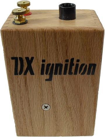
2 1.0 Installation Wiring DX Firebox is designed to be an electronic replacement for Pontiac & Ford buzz coils when operated on DC. Installation may be positive or negative ground. Simply observe the RED and BLACK terminals with respect to battery polarity. Installation Wiring DX Ignition Page 2
3 When wiring the input connections use at least 16ga stranded wire, 10 amp fuse, and ignition switch. Grounding is very important; make sure the engine and battery have good chassis connections. It is recommended to test and inspect timer points for proper electrical ground connection to engine. The timer condenser is not required for the operation of DX ignition and it may be removed. If the condenser is good, you may choose to leave it connected allowing an easy switch between DX ignition and original buzz coil. For the best performance clean and gap timer points. Follow the procedure defined by Fairmont to adjust the timer points interval to 1/12 of an engine revolution which is the equivalent of 30. The timer interval determines the number of crankshaft rotation degrees the buzz coil will fire. Significantly less than 30 may cause high RPM stalling, spark plug fouling and slow timer lever response. Greater than 30 effectively advances the ignition timing with relationship to timer lever position. You may remove the 4 brass screws and lid to observe the red LED on the electronic buzz coil. The LED illuminates when the points are closed. The spark plug wire must be resistive or suppression wire. Due to the DX ignition high output copper or steel core plug wire should not be used because it may act as an antenna causing RFI and unwanted noise. The recommended spark plug gap is Resistor or non-resistor spark plugs may be used; however non resistor plugs may contribute noise to other electronic devices. DX Ignition Page 3
4 Ignition Timing Degrees 2.0 Specifications Operating Temperature Input Voltage On Current Output Voltage Oscillator frequency Dwell Spark Duration 0 F-120 F typical (all components exceed 220 F) v Positive Ground <1.5amp average/5.2amp peak >30kv peak 260Hz 3 milliseconds 1.6 millisecond 15 Ignition Timing vs RPM 3.0ms dwell Engine RPM The above chart shows the relationship between ignition timing and RPM with the timer lever in the center or vertical position. At 100 RPM the timing is 13.2 advanced and at 2000 RPM the timing is retarded 21. This is why the timer lever needs to be pulled back when starting the engine and pushed forward when running at higher RPM. DX Ignition Page 4
5 DX Firebox Schematic DX Ignition Page 5
6 3.0 Glossary of Terms High Tension High Voltage, voltage is electric tension measured between two points. Low Tension Low Voltage, voltage is electric tension measured between two points. Dwell Time Dwell refers to the time the ignition coil is charging. Negative Ground A negative ground system has the negative terminal of the battery connected to a common point such as a vehicle chassis to provide the same potential throughout the vehicle. Positive Ground A positive ground system has the positive terminal of the battery connected to a common point such as a vehicle chassis to provide the same potential throughout the vehicle. Positive ground potential promotes galvanic corrosion on vehicle body parts and frames and is not commonly used today. The electrical wiring itself is sacrificed however better insulation offers protection and reduces deterioration. Spark Plug Heat Range The heat range of a spark plug determines the temperature of the tip of the spark plug while the engine is running. The correct temperature maintains efficiency and keeps the plug clean. The temperature range does not significantly affect electrical characteristics of the plug. Timer The timer is a cam actuated mechanical device that provides a signal to a buzz coil. Points Points are a cam actuated mechanical switch that provides a signal to an ignition coil. Condenser The condenser is a capacitor that connects to ignition points. The function of the condenser is to provide a path for the collapsing magnetic field of the primary side of an ignition coil when the points open. Average Current Current measured with respect to time. Peak Current Current measured at its maximum value. Ignition Coil A device with a pulsing low voltage DC input and a high voltage output. Ignition Module The primary function of an automotive ignition module is to interpret incoming cam or crank shaft signals and deliver a pulsed regulated current flow to an ignition coil corresponding to engine position. DX Ignition Page 6
7 Coil Primary Inductance Inductance measured on the primary or low voltage input side of an ignition coil. Inductance unit of measure is henrys. Typical ignition coil primary inductance ranges between 1-10mh (millihenry). Primary Resistance Resistance measured on the primary or low voltage input side of an ignition coil. Resistance is measured in ohms. Typical coil primary resistance ranges between ohms. Secondary Resistance Resistance measured on the secondary or high voltage output side of an ignition coil. Typical coil secondary resistance ranges between 5K-10K ohms. Coil Turns Ratio Coil turns ratio refers to the number of winding on an ignition coil primary and secondary. Typical coil ratio is 1:100. RFI Radio Frequency Interference or Electromagnetic Interference Resistor or Suppression Wires Suppression spark plug wires have internal resistance that reduces the emission of RFI. Resistor Spark Plug A spark plug with internal resistance reduces the emission of RFI. Ignition Timing Ignition timing on an internal combustion engine determines when an ignition spark is initiated based on the position of mechanical components of the engine. Ignition Coil Polarity A typical ignition coil generally can operate polarity in either direction. When the polarity of the primary side of an ignition coil is reversed the output reverses respectively. Spark Polarity The polarity on the secondary side of an ignition coil determines the direction of high voltage electron flow. The ideal direction for a spark plug is for the spark to jump from the center electrode to the ground electrode. On a single coil two cylinder ignition system one spark plug always fires in reverse polarity. Polarity In a Direct Current circuit electrons flow in one direction from the negative pole to the positive pole. Identifying the poles identifies the polarity. When the poles are reversed the polarity is reversed. Inductance The current flowing through a conductor induces a magnetic field around the conductor. The voltage across an inductor is equal to the product of its inductance and the time rate of change of the current through it. Inductance is measured in henry. DX Ignition Page 7


8 Contact Information Brett Scott 204 S. 5 th street Ethan, SD (605) bscott@santel.net 4.0 Operation & Precautions Warning High Voltage! When installing, operating, or servicing the electronic buzz coil use extreme care and recognize the high voltage potential. Important! Do not operate the electronic buzz coil without a defined high voltage path! Interrupting the high voltage path poses a health risk and also possible damage to the buzz coil. The High voltage path must be a complete circuit from the coil tower to ground. A failed or disconnected plug wire can cause the spark to arc internal to the coil causing failure. One year warranty from purchase date. Purchase Date Rev. 9/6/2017 DX Ignition Page 8
Contents. DX Ignition Page 2
 Contents 1.0 Intent 2.0 Specifications 3.0 Installation 4.0 Operation Precautions 5.0 Repair 6.0 Parts List 7.0 Glossary of Terms 8.0 Contact Information DX Ignition Page 2 1.0 Intent The purpose of this
Ignition Coil Current Waveforms 2007 Honda Accord SE 4CYL
 P a g e 1 Ignition Coil Current Waveforms 2007 Honda Accord SE 4CYL With a current clamp and a cheap scope, it is easy to monitor the ignition coil currents and quickly diagnose a bad ignition coil. The
CHAPTER 6 IGNITION SYSTEM
 CHAPTER 6 CHAPTER 6 IGNITION SYSTEM CONTENTS PAGE Faraday s Law 02 The magneto System 04 Dynamo/Alternator System 06 Distributor 08 Electronic System 10 Spark Plugs 12 IGNITION SYSTEM Faraday s Law The
AUTOMOTIVE ENGINEERING SECTION
 PURPOSE OF IGNITION SYSTEM The ignition system supplies high-voltage surges as high as 47,000 volts (in some electronic systems) to the spark plugs in the engine cylinders. These surges produce electric
2014 Hyundai Veloster ENGINE Ignition System - Veloster Turbo. Ignition System - Veloster Turbo
 DESCRIPTION AND OPERATION DESCRIPTION 2013-14 ENGINE Ignition System - Veloster Turbo Ignition timing is controlled by the electronic control ignition timing system. The standard reference ignition timing
Battery powered ignition
 Battery powered ignition A typical battery powered ignition uses a transformer, a several switching devices, and a power source. The power source is the battery. Battery powered ignition The first switch
ATASA 5 th. ATASA 5 TH Study Guide Chapter 27 Pages Ignition Systems 68 Points. Please Read the Summary
 ATASA 5 TH Study Guide Chapter 27 Pages 810 835 68 Points Please Read the Summary Before We Begin Keeping in mind the Career Cluster of Transportation, Distribution & Logistics Ask yourself: What careers
WEAPONX CIRCUIT COMPRESSION
 WeaponX Ignition Coil Technology WeaponX designs and employs the greatest performance proven technologies available. The creation of a high quality ignition system has been a challenging process for OEMS
THE FOURTH STATE. Gaining a universal insight into the diagnosis of automotive ignition systems. By: Bernie Thompson
 THE FOURTH STATE Gaining a universal insight into the diagnosis of automotive ignition systems By: Bernie Thompson Did you know that the forth state of matter powers the spark ignition internal combustion
Sensors & Controls. Everything you wanted to know about gas engine ignition technology but were too afraid to ask.
 Everything you wanted to know about gas engine ignition technology but were too afraid to ask. Contents 1. Introducing Electronic Ignition 2. Inductive Ignition 3. Capacitor Discharge Ignition 4. CDI vs
DTC P0351, P0352, P0353, P0354, P0355, P0356, P0357, or P0358
 DTC Descriptor DTC P0351 Ignition coil 1 control circuit DTC P0352 Ignition coil 2 control circuit DTC P0353 Ignition coil 3 control circuit DTC P0354 Ignition coil 4 control circuit DTC P0355 Ignition
The Physics of the Automotive Ignition System
 I. Introduction This laboratory exercise explores the physics of automotive ignition systems used on vehicles for about half a century until the 1980 s, and introduces more modern transistorized systems.
UNIT 4 IGNITION SYSTEMS
 UNIT 4 IGNITION SYSTEMS Ignition Systems Structure 4.1 Introduction Objectives 4.2 Ignition System Types 4.3 Comparison between Battery and Magneto Ignition System 4.4 Drawbacks (Disadvantages) of Conventional
IGNITION/HEADLAMP SWITCH
 IGNITION/HEADLAMP SWITCH DO NOT modify the ignition/headlamp switch wiring to circumvent the automatic-on headlamp feature. Visibility is a major concern for motorcyclists. Failure to have proper headlamp
Chapter 4 Ignition & Electrical Systems
 Chapter 4 Ignition & Electrical Systems Chapter 4 Section A Study Aid Questions Fill in the Blanks 1. Ignition systems can be divided into two classifications: systems or systems for reciprocating engines.
Ignition System Fundamentals
 Ignition System Fundamentals Chapter 37 Objectives Describe the functions of ignition system parts Explain the operation of points, electronic, and computer ignition systems Give an overview of the different
The galvanic separation of the primary or actuating circuit and the load circuits
 RELAY BASICS Relays are electro magnetically operated switches. An actuating current on a coil operates one or more galvanically separated contacts or load circuits. The electro mechanical relay is a remote
CPi. CoiL PACK IGNiTioN FOR AViATiON. For 4,6 and 8 cylinder 4 stroke applications. Please read the entire manual before beginning installation.
 1 CPi CoiL PACK IGNiTioN FOR AViATiON Coil pack (4 cylinder) Coil pack (6 cylinder) For 4,6 and 8 cylinder 4 stroke applications. Please read the entire manual before beginning installation. Software version
Points Conversion. Optical Trigger Conversion. Specifications. Applications. Optical Trigger - Installation Kits CRANECAMS.
 Points Conversion Optical Trigger Conversion Easy to install in less than 1 hour! Converts points-type distributor to precision optically triggered system! No maintenance! Drives HI-6, HI-6S and most aftermarket
The Electrical System. by Kate Elfers and Mun Yong Jang
 The Electrical System by Kate Elfers and Mun Yong Jang Important links: Video overview of system: https://www.youtube.com/watch? v=w94iksaqwuo Understanding AC vs DC animation: https://www.youtube.com/watch?
Ladies and Gentlemen... We Have Ignition!
 FEATURE Ladies and Gentlemen... We Have Ignition! The coordination of ignition, fuel delivery and basic engine function is required before internal combustion can take place. Here, we'll look at the ignition
Wiring Diagram 7 Amp 2 Step (7642MC) Ignition Box - No Booster ENGINE BLOCK LOWER LIMIT ARMING WIRE ORANGE GREEN BLACK DISTRIBUTOR LOOM (PRE-MADE)
 Ignition Box - No Booster ENGINE BLOCK LOWER LIMIT ARMING WIRE ORANGE GREEN BLACK DISTRIBUTOR LOOM (PRE-MADE)") Wiring Diagram 7 Amp 2 Step (7642MC) Ignition Box - No Booster IGNITION SWITCH 7 AMP 2 STEP TO TACH 7642MC LOWER LIMIT ARMING WIRE WHITE ENGINE BLOCK DISTRIBUTOR LOOM (PRE-MADE) DISTRIBUTOR COIL BATTERY
Wiring Diagram 7 Amp 2 Step (7642MC) Ignition Box - No Booster IGNITION SWITCH 7 AMP 2 STEP TO TACH 7642MC LOWER LIMIT ARMING WIRE WHITE ENGINE BLOCK DISTRIBUTOR LOOM (PRE-MADE) DISTRIBUTOR COIL BATTERY
INSTALLATION INSTRUCTIONS
 INSTALLATION INSTRUCTIONS WARNING: WARNING: www.altronicinc.com DEVIATION DEVIATION FROM THESE FROM INSTRUCTIONS THESE INSTRUCTIONS MAY LEAD MAY TO LEAD IMPROPER TO IMPROPER OP- ERATION OF ENGINE THE MACHINE
AUTOMOTIVE IGNITION SYSTEMS
 AUTOMOTIVE IGNITION SYSTEMS ABSTRACT This report describes the differences and similarities between a 1964 Mustang traditional ignition system and that of my 2014 Jeep. To help you understand the process
Understanding The HA2500's Horiz Driver Test
 Understanding The HA2500's Horiz Driver Test Horizontal output stage symptoms and component failures are often caused by problems in the horizontal driver stage. The horizontal driver stage is seldom suspected,
Unit AE01K Knowledge of Locating and Correcting Simple Electrical Faults in the Automotive Workplace
 Assessment Requirements Unit AE01K Knowledge of Locating and Correcting Simple Electrical Faults in the Automotive Workplace Content: Basic electrical principles a. Explain the direction of current flow
ECCT. Electrically Cranked Coil Tester Instruction Manual
 TM ECCT Electrically Cranked Coil Tester Instruction Manual Mictel LLC 244N. 17 th Street Kenilworth, NJ 07033 web: www.modeltetimer.com ECCT Contents The ECCT contains the following items: Quantity Description
Before performing spark test, ensure ignitor is properly grounded.
 Page 1 of 10 IGNITION CHECKS SPARK TEST NOTE: Before performing spark test, ensure ignitor is properly grounded. 1. Disconnect high tension coil wire from distributor. Hold coil wire approximately 1/2"
Handout Activity: HA773
 Charging system HA773-2 Handout Activity: HA773 Charging system The charging system allows for a means to recharge the battery and allow for electrical usage of components in the vehicle. The charging
MSD Stacker-4 (4-Channel), PN 7010 Stacker-8 (8-Channel), PN 7020
, PN 7010 Stacker-8 (8-Channel), PN 7020") INSTALLATION INSTRUCTIONS 1 MSD Stacker-4 (4-Channel), PN 7010 Stacker-8 (8-Channel), PN 7020 Important: Read these instructions before attempting this installation! Parts Included: 1 - MSD Stacker Ignition
INSTALLATION INSTRUCTIONS 1 MSD Stacker-4 (4-Channel), PN 7010 Stacker-8 (8-Channel), PN 7020 Important: Read these instructions before attempting this installation! Parts Included: 1 - MSD Stacker Ignition
Electromagnetic Induction, Faraday s Experiment
 Electromagnetic Induction, Faraday s Experiment A current can be produced by a changing magnetic field. First shown in an experiment by Michael Faraday A primary coil is connected to a battery. A secondary
16.01 Theory Module INPUTS
 16.01 Theory Module INPUTS Crankshaft position sensor Camshaft position sensor Knock sensor (some engine types) Barometric pressure sensor Intake air temperature sensor Engine coolant temperature sensor
IGNITION SYSTEMS DESCRIPTION EARLY INDUCTION TYPE
 IGNITION SYSTEMS Turbine engine ignition systems fall into two general classifications. The induction type produces high-tension sparks by conventional induction coils. The capacitor type causes ignition
Study of cooling, lubrication and ignition system in diesel and petrol engines.
 Study of cooling, lubrication and ignition system in diesel and petrol engines. Aim: - To study the conventional battery ignition system Construction: The function of battery ignition system is to produce
CSDA Best Practice. Hi-Cycle Concrete Cutting Equipment. Effective Date: Oct 1, 2010 Revised Date:
 CSDA Best Practice Title: Hi-Cycle Concrete Cutting Equipment Issue No: CSDA-BP-010 : Oct 1, 2010 Revised : Introduction Hi-cycle/high frequency concrete cutting equipment has become more prevalent in
PowerCORE 8.8mm Hybrid Super Conducting Wire CORETECH OVERVIEW
 PowerCORE 8.8mm Hybrid Super Conducting Wire CORETECH OVERVIEW The ideal ignition system comprises of various components to improve power output but hidden among the power output various other important
ELECTRICITY: INDUCTORS QUESTIONS
 ELECTRICITY: INDUCTORS QUESTIONS No Brain Too Small PHYSICS QUESTION TWO (2017;2) In a car engine, an induction coil is used to produce a very high voltage spark. An induction coil acts in a similar way
Asynchronous Restriking CDI 2 channel
 Asynchronous Restriking CDI 2 channel Parts List ARC-2 module Decals Power Cable Fuse Specifications Operating Voltage: 8-20V Operating Current: Max Operating RPM: Ambient Temp range: Ignition inputs:
IGNITION SYSTEM COMPONENTS AND OPERATION
 69 IGNITION SYSTEM COMPONENTS AND OPERATION Figure 69-1 A point-type distributor from a hot rod being tested on a distributor machine. WARNING: The spark from an ignition coil is strong enough to cause
1984 Jeep CJ7. IGNITION SYSTEM - SOLID STATE' 'Distributors & Ignition Systems MOTORCRAFT SOLID STATE IGNITION (SSI)
") TESTING SECONDARY CIRCUIT CHECK CAUTION: When checking secondary voltage, do not remove spark plug wires from spark plugs No. 3 on 4-cylinder, No. 1 or 5 on 6-cylinder and No. 3 or 4 on V8 Engines. 1.
TESTING SECONDARY CIRCUIT CHECK CAUTION: When checking secondary voltage, do not remove spark plug wires from spark plugs No. 3 on 4-cylinder, No. 1 or 5 on 6-cylinder and No. 3 or 4 on V8 Engines. 1.
 APGENCO/APTRANSCO Assistant Engineer Electrical Previous Question Papers Q.1 The two windings of a transformer is conductively linked. inductively linked. not linked at all. electrically linked. Q.2 A
Shock Tube Saver System Installation and Operation Manual Duke Part No Rev. B
 Shock Tube Saver System Installation and Operation Manual Duke Part No. 515800 Rev. B INTRODUCTION The Duke Pro Shock Tube Saver System (STSS) shock tube initiator is designed to provide a substitute for
MSD Pro Mag Information
 MSD 44 Amp Pro Mag Generator Clockwise Rotation - PN 8130, PN 81303, PN 81305, PN 81307 Counterclockwise Rotation PN 8140, PN 81403, PN 81405, PN 81407 Parts Included In This Kit: 1 44 Amp Pro Mag Generator
2014 ELECTRICAL TECHNOLOGY
 SET - 1 II B. Tech I Semester Regular Examinations, March 2014 ELECTRICAL TECHNOLOGY (Com. to ECE, EIE, BME) Time: 3 hours Max. Marks: 75 Answer any FIVE Questions All Questions carry Equal Marks ~~~~~~~~~~~~~~~~~~~~~~~~~~
Electricity. Chapter 20
 Electricity Chapter 20 Types of electric charge Protons + charge Electrons - charge SI unit of electric charge is the coulomb (C) Interactions between charges Like charges repel Opposite charges attract
ABB ! CAUTION. Type KRV Directional Overcurrent Relay E 1.0 APPLICATION 2.0 CONSTRUCTION AND OPERATION. Instruction Leaflet
 ABB Instruction Leaflet 41-137.2E Effective: February 1994 Supersedes I.L. 41-137.2D, Dated February 1973 ( )Denotes Change Since Previous Issue. Type KRV Directional Before putting relays into service,
Update. This week A. B. Kaye, Ph.D. Associate Professor of Physics. Michael Faraday
 10/26/17 Update Last week Completed Sources of Magnetic Fields (Chapter 30) This week A. B. Kaye, Ph.D. Associate Professor of Physics (Chapter 31) Next week 30 October 3 November 2017 Chapter 32 Induction
Electrical Systems. Introduction
 Electrical Systems Figure 1. Major Components of the Car s Electrical System Introduction Electricity is used in nearly all systems of the automobile (Figure 1). It is much easier to understand what electricity
04. Ignition and Exhaust system
 New Polytechnic Kolhapur Page 1 of 10 04. Ignition and Exhaust system 4.1 Introduction to Ignition System 4 Marks Requirements of ignition system. Magneto and Battery Ignition systems (Working only). Firing
UNIT 3: GENErAL ELECTriCAL SySTEM DiAGNOSiS
 Electrical/Electronic Systems UNIT 3: GENErAL ELECTriCAL SySTEM DiAGNOSiS LESSON 3: TEST electrical circuits I. Types of electrical circuit tests and electrical faults A. Different types of electrical
Chapter 22. Electromagnetic Induction
 Chapter 22 Electromagnetic Induction 22.1 Induced Emf and Induced Current There are a number of ways a magnetic field can be used to generate an electric current. It is the changing field that produces
SECTION M. ELECTRICAL. Section Description Page No.
 SECTION M. ELECTRICAL. Section Description Page No. M.1 General Page 2 M.2 Alternator Page 2 M.3 Battery Page 7 M.4 Hazard Warning System Page 7 M.5 Brake Fail Warning System Page 8 M.6 Seat Belt Warning
Pretest Module 21 Units 1-4 AC Generators & Three-Phase Motors
 Pretest Module 21 Units 1-4 AC Generators & Three-Phase Motors 1. What are the two main parts of a three-phase motor? Stator and Rotor 2. Which part of a three-phase squirrel-cage induction motor is a
Welcome to PTI--Photon Technology International--Optical Building Blocks!
 Search: GO Power Supplies Model LPS-220 Lamp Power Supply OPERATION MANUAL CONTENTS 1. DESCRIPTION Introduction Specifications 2. INSTALLATION Arc Lamps Tungsten-Halogen Lamps 3. OPERATION Arc Lamps Tungsten-Halogen
Unit 32 Three-Phase Alternators
 Unit 32 Three-Phase Alternators Objectives: Discuss the operation of a three-phase alternator. Explain the effect of rotation speed on frequency. Explain the effect of field excitation on output voltage.
Installation Instructions for Lingenfelter Shift Light Controller with green LED
 Installation Instructions for Lingenfelter Shift Light Controller with green LED PN: L460080000 1557 Winchester Road Decatur, Indiana 46733 260 724 2552 phone 260 724 8761 fax www.lingenfelter.com Parts
MD10. Engine Controller. Installation and User Manual for the MD10 Engine Controller. Full Version
 MD10 Engine Controller Installation and User Manual for the MD10 Engine Controller. Full Version File: MartinMD10rev1.4.doc May 16, 2002 2 READ MANUAL BEFORE INSTALLING UNIT Receipt of shipment and warranty
Ledex Drive Electronics and Coil Suppressors
 Ledex and Coil Suppressors Ledex Coil Suppressors A voltage is generated by a changing magnetic field in proximity to a currentcarrying member. The equation E = N dø /dt, describes this by saying that
Motional EMF. F = qvb
 Motional EMF When a conducting rod moves through a constant magnetic field, a voltage is induced in the rod. This special case of electromagnetic induction arises as a result of the magnetic force that
MAGNETO REPLACEMENT. Pre-Unit Twin Cylinder Motorcycles. ELECTRONIC IGNITION SYSTEM For 4 Stroke. With 12 VOLT Electrics, POS/ NEG Ground
 Sure ー Fire MAGNETO REPLACEMENT ELECTRONIC IGNITION SYSTEM For 4 Stroke Pre-Unit Twin Cylinder Motorcycles With 12 VOLT Electrics, POS/ NEG Ground SYSTEM TYPE: PAMT1 2 Sure-Fire System Contents: MAGNETO
Chapter 31. Faraday s Law
 Chapter 31 Faraday s Law Michael Faraday 1791 1867 British physicist and chemist Great experimental scientist Contributions to early electricity include: Invention of motor, generator, and transformer
Ch 4 Motor Control Devices
 Ch 4 Motor Control Devices Part 1 Manually Operated Switches 1. List three examples of primary motor control devices. (P 66) Answer: Motor contactor, starter, and controller or anything that control the
DC CIRCUITS ELECTROMAGNETISM
 DC CIRCUITS 1. State and Explain Ohm s Law. Write in brief about the limitations of Ohm s Law. 2. State and explain Kirchhoff s laws. 3. Write in brief about disadvantages of series circuit and advantages
MGL Avionics AvioGuard. Fault protected, wide input range, isolated, DC to DC converter for avionics applications
 MGL Avionics AvioGuard Fault protected, wide input range, isolated, DC to DC converter for avionics applications General The MGL Avionics AvioGuard is a fault protected DC to DC converter. It is able to
AUTOMOTIVE TECHNOLOGY Electricity and Electronics
 AUTOMOTIVE TECHNOLOGY Electricity and Electronics Al Santini Retired, College of DuPage Glen Ellyn, Illinois Jack Erjavec, Series Editor Professor Emeritus, Columbus State Community College Columbus, Ohio
ELECTRICITY KIT - for DC and AC
 ELECTRICITY KIT - for DC and AC Cat: EM1763-001 KIT LAYOUT 1 GENERAL DESCRIPTION: This kit is designed to perform important basic experiments with electricity. To study electric circuits, switches, lamps,
Almost 200 years ago, Faraday looked for evidence that a magnetic field would induce an electric current with this apparatus:
 Chapter 21 Electromagnetic Induction and Faraday s Law Chapter 21 Induced EMF Faraday s Law of Induction; Lenz s Law EMF Induced in a Moving Conductor Changing Magnetic Flux Produces an E Field Inductance
Tempest Tech-Tip 0813
 August 2013 Tempest Tech-Tip 0813 Light My Fire Background Without a good spark, spark plugs can t get the job done well. How do you keep good sparks coming, so your spark plugs can light your fire with
Today s lecture: Generators Eddy Currents Self Inductance Energy Stored in a Magnetic Field
 PHYSICS 1B Today s lecture: Generators Eddy Currents Self Inductance Energy Stored in a Magnetic Field PHYSICS 1B Lenz's Law Generators Electric generators take in energy by work and transfer it out by
Electronic Dynamo Regulator INSTRUCTION MANUAL. COPYRIGHT 2014 CLOVER SYSTEMS All Rights Reserved
 DRM TM DRM-HP TM Electronic Dynamo Regulator INSTRUCTION MANUAL COPYRIGHT 2014 CLOVER SYSTEMS All Rights Reserved INTRODUCTION The Clover Systems DRM is a state-of-the art all-electronic voltage and current
A - Add New Information C - Change Existing Information D - Delete Information. Page 7. Delete the fourth paragraph beginning CAUTION
 ABB Effective: November 1990 This Addendum Supersedes all Previous Addenda Addendum to Instruction Leaflet 41-137.3H Type KRD-4 Directional Overcurrent Ground Relay A - Add New Information C - Change Existing
Chrysler Electronic Ignition System
 1 of 11 1/6/2010 11:02 PM Chrysler Electronic Ignition System Classic Winnebago's Post by: DaveVA78Chieftain on August 13, 2009, 10:15 PM Components The Chrysler Electronic Ignition System consists of
IGNITION SYSTEM 8D - 1 IGNITION SYSTEM TABLE OF CONTENTS
 LH IGNITION SYSTEM 8D - 1 IGNITION SYSTEM TABLE OF CONTENTS page AND IGNITION SYSTEM...1 SPARK PLUGS-PLATINUM....1 COIL ON PLUG...1 CRANKSHAFT POSITION SENSOR....2 CAMSHAFT POSITION SENSOR....3 KNOCK SENSOR....5
TECHNICAL GUIDE FOR PROXIMITY SENSORS DEFINITIONS YAMATAKE PROXIMITY SENSOR CATEGORIES
 TECHNICAL GUIDE FOR PROXIMITY SENSORS DEFINITIONS "" includes all sensors that detect the presence of a metallic object approaching the sensing face or near the sensing face without mechanical contact.
IAX/LUX/LEX Series Low-Depth, Hydraulic-Magnetic Circuit Breakers. Introduction Configurations Delay Curves Operating Characteristics Decision Tables
 IAX/LUX/LEX Series Low-Depth, Hydraulic-Magnetic Circuit Breakers Introduction Configurations Delay Curves Operating Characteristics Decision Tables 23 24 27 28 29 IAX/LUX/LEX Series Low-Depth, Hydraulic-Magnetic
Air Cooled Engine Technology. Roth 9 th Ch 14 Elect. System Service Pages
 Roth 9 th Ch 14 Elect. System Service Pages 245 276 1. is the term used to describe periodic, preventative maintenance done to the ignition system of any engine. It may often times also include fuel system,
Transmission & Distribution Glossary of Electrical Terms
 Transmission & Distribution Glossary of Electrical s Breaker Panel Bushing Circuit Circuit Breaker Conductor Conduit Consumption Current Distribution Electricity (Static vs. Current) Electron Feeder The
AUTOMOTIVE MAINTENANCE TECHNOLOGY SUBJECT : AUTOTRONIC 2 TITLE: TRANSISTORISED IGNITION WITH HALL GENERATOR TI-H
 Transistorized ignition with Hall generator TI-H In addition to the breaker-triggered transistorized ignition system (TI-B), there are two other versions of transistorized ignition with Hall triggering
Marine and Outdoor Power Equipment Technician Level 2
 Level 2 Unit: B2 Trade Mathematics II Level: Two Duration: 16 hours Theory: Practical: 16 hours 0 hours Overview: This unit is designed to provide the apprentice with the knowledge and ability to apply
ELECTRICAL / GENERAL INFORMATION
 ELECTRICAL / GENERAL INFORMATION General Information Reading Electrical Schematics The schematic is made up of individual circuits laid out in a sequence of related functions. It is formatted with all
#T84-92: ERRATIC LIGHTS/DIGITAL DISPLAY ELEC. SYSTEM DISTURBANCES - (Aug 2, 1984)
") #T84-92: ERRATIC LIGHTS/DIGITAL DISPLAY ELEC. SYSTEM DISTURBANCES - (Aug 2, 1984) MODELS AFFECTED: 1980-1985 CADILLACS EQUIPPED WITH DEFI, DFI, CCC OR CIMARRON EFI A number of engine performance conditions,
#T84-92: ERRATIC LIGHTS/DIGITAL DISPLAY ELEC. SYSTEM DISTURBANCES - (Aug 2, 1984) MODELS AFFECTED: 1980-1985 CADILLACS EQUIPPED WITH DEFI, DFI, CCC OR CIMARRON EFI A number of engine performance conditions,
Wired Real Time GPS Installation Instructions
 Wired Real Time GPS Installation Instructions This page intentionally left blank. TABLE OF CONTENTS 1. Introduction 2 2. Selecting the Mounting Location for the Device. 3 3. Mounting the Device 5 4. Optional
Electronic Dynamo Regulator INSTRUCTION MANUAL. COPYRIGHT 2014 CLOVER SYSTEMS All Rights Reserved
 DRM TM DRM-HP TM Electronic Dynamo Regulator INSTRUCTION MANUAL COPYRIGHT 2014 CLOVER SYSTEMS All Rights Reserved INTRODUCTION The Clover Systems DRM is a state-of-the art all-electronic voltage and current
Module 22 Ignition Systems - Outputs
 Module 22 Ignition Systems - Outputs Author: Grant Swaim E-mail: sureseal@nr.infi.net URL: www.tech2tech.net Phone: (336) 632-9882 Fax: (336) 632-9688 Postal Address: Tech-2-Tech Website PO Box 18443 Greensboro,
TWIN CYLINDER MOTORCYCLES WITH POINTS IN THE SIDE CASING
 Sure ー Fire ELECTRONIC FOR UNIT CONSTRUCTION TWIN CYLINDER MOTORCYCLES WITH POINTS IN THE SIDE CASING & 12 VOLT ELECTRICS POSITIVE OR NEGATIVE GROUND SYSTEM TYPE: PA2 2 Sure-Fire System Contents: MODULE
Contacts The moveable contact, which is the one affected by the armature is sometimes referred to as the hinge contact.
 Relays & Wiring 101 Basically, a relay is an electrically operated, remotely controlled switch. A simple electromagnetic relay is an adaptation of an electromagnet. It consists of a coil of wire surrounding
DC motor theory. Resources and methods for learning about these subjects (list a few here, in preparation for your research):
:") DC motor theory This worksheet and all related files are licensed under the Creative Commons Attribution License, version 1.0. To view a copy of this license, visit http://creativecommons.org/licenses/by/1.0/,
DC motor theory This worksheet and all related files are licensed under the Creative Commons Attribution License, version 1.0. To view a copy of this license, visit http://creativecommons.org/licenses/by/1.0/,
SVE135 Sealed High-Voltage Contactor Having High Overcurrent Withstand Capability
 VE135 ealed High-Voltage Contactor Having High Over Withstand Capability AKA, Yasuhiro * HIBA, Yuji * AKURAI, Yuya * A B T R A C T The spread of environmentally friendly vehicles mounted with large-capacity
Tri-Spark Ignition System Installation Triple Cylinder TRI-0001
 Tri-Spark Ignition System Installation Triple Cylinder TRI-0001 There are potentially lethal high voltages produced at the ignition coils and spark plugs, therefore every precaution must be taken to prevent
SALDET SALES & SERVICE, INC. CLINTON TOWNSHIP, MICHIGAN
 Form 1254 BRAKETRON Electronic Motor Brake Instructions SALDET SALES & SERVICE, INC. CLINTON TOWNSHIP, MICHIGAN TABLE OF CONTENTS SECTION TITLE PAGE I. Introduction 1 II. Specifications 1 III. Principles
Manual Installation & Operation
 Manual Installation & Operation Model: NCxxLxx 12A or 30A Solid State Solar Charging Regulator and 12A Load Controller. 231 Patent #: 5,642,030 Applies Page 1 Warnings When Installing, connect grounds,
ELECTRICAL TABLE OF CONTENTS
 ELECTRICAL TABLE OF CONTENTS Electrical Table of Contents General Information...205 Reading Electrical Schematics...205 Theory Of Operation Information...206 Diagnostic Information...206 Wire Color Abbreviation
OTHER ELECTRICAL MEASURING DEVICES
 Other measuring devices are used to aid operators in determining the electric plant conditions at a facility, such as the ampere-hour meter, power factor meter, ground detector, and synchroscope. EO 1.2
SL Series Application Notes. SL Series - Application Notes. General Application Notes. Wire Gage & Distance to Load
 Transportation Products SL Series - Application Notes General Application Notes vin 2 ft. 14 AWG The SL family of power converters, designed as military grade standalone power converters, can also be used
Electricity MR. BANKS 8 TH GRADE SCIENCE
 Electricity MR. BANKS 8 TH GRADE SCIENCE Electric charges Atoms and molecules can have electrical charges. These are caused by electrons and protons. Electrons are negatively charged. Protons are positively
12-Volt Negative Ground Installation Instructions
 12-Volt Negative Ground Installation Instructions For Part Number: 1183 CAUTION!!! Before installing, please read the following important information... 1. The Ignitor is designed for 12-Volt negative
Time scale: from 0.05s to 100h Multi-function Plug-in for use with 90.02, 90.03, and sockets
 86 Series - Timer modules Features 86.00 86.30 Timer modules for use in conjunction with relay & socket. 86.00 - Multi-function & multi-voltage timer module 86.30 - Bi-function & multi-voltage timer module
INSTALLATION MANUAL. Model: PLUS For Technical Assistance, please call (800) , or visit
 , or visit") R Vehicle Security INSTALLATION MANUAL Model: PLUS-4700 This device complies with part 15 of the FCC rules. Operation is subject to the following two conditions: (1) This device may not cause harmful interference;
R Vehicle Security INSTALLATION MANUAL Model: PLUS-4700 This device complies with part 15 of the FCC rules. Operation is subject to the following two conditions: (1) This device may not cause harmful interference;
Timing is everything with internal combustion engines By: Bernie Thompson
 Timing is everything with internal combustion engines By: Bernie Thompson As one goes through life, it is said that timing is everything. In the case of the internal combustion engine, this could not be
Diesel Technology: Electrical and Electronic Systems
 Diesel Technology: Electrical and Electronic Systems Instructional/Task Analysis 2. Composition of atoms Unit 1: Introduction to Diesel Electrical and Electronic Systems 3. Electrical charges in atoms