INSTALLATION AND CUSTOMER CARE INFORMATION 80 SERIES & 90 SERIES TREATMENT STATIONS
|
|
|
- Oswald Alfred Thompson
- 5 years ago
- Views:
Transcription

 Phone: 800-257-7407 or 270-651-7407 Fax:")
1 INSTALLATION AND CUSTOMER CARE INFORMATION 80 SERIES & 90 SERIES TREATMENT STATIONS Customer Service and Technical Support: 8:00 AM to 5:00 PM central (M-Th) 8:00 AM to 4:30 PM central (Fri) Phone: or Fax:
2 INDEX PAGE 3 PARTS LIST PAGE 4 INSTALLING THE BASE MODULE (Step 1) PAGE 5 INSTALLING PIVOTING WORK SURFACE TOP (Step 2) PAGE 5 INSTALLING OPTIONAL INSTRUMENTATION (Step 3) PAGE 6 INSTALLING PRO CENTER (Step 4) PAGE 7 INSTALLING UPPER MODULE & TASK LIGHT (Step 5) PAGE 8 ELECTRICAL INFORMATION AND CIRCUIT DIAGRAMS PAGE 9 LOCATING WIRED CIRCUITS PAGE CIRCUIT DIAGRAMS #1 & 2 PAGE AIRGLIDE SIDE KICK OPENER SCHEMATIC DIAGRAM PAGE 14 SETTING AND USING THE TIMER CLOCK PAGE 15 SOLID SURFACE CARE AND MAINTENANCE PAGE 16 DRAWER AND HINGE ADJUSTMENTS GENERAL DESCRIPTION OF CABINET SECTIONS UPPER MODULE 21 TASK LIGHT 1:00 MID SECTION 3" EQUIPMENT DRAWER 5" BASE MODULE page 2


3 8-1/4" Flat Washer SKU# S19160 page 3

4 TREATMENT STATION INSTALLATION - Step #1 Installing Base Module 1. Set the lower module over plumbing by tilting the cabinet upward on doctor s side and angling cabinet down over pipes. Note - If you must lift the cabinet over plumbing, first remove excess weight by removing drawers, doors, roll-out tubs etc. A B 2. Adjust legs to uneven floor by inserting a flat blade screwdriver through top of floor panels an turning clockwise (A) or by inserting screwdriver into side of leg from underneath bottom panel (B). Note - Attaching cabinet to the floor with fasteners is at the customers discretion. The weight of the unit is generally sufficient to prevent movement after installation is complete. page 4
.")
. 3.")

5 TREATMENT STATION INSTALLATION - Step #2 Installing Pivoting Work Surface Top 1. Attach the assistants work surface to the arm mounting plate using four 1 x 1/4 x #20 machine screws (A). Level the work surface using the adjustment screws (B). 2. Attach the optional Doctor s/assistant s package with 4-3/4" x 1/4" #20 hex bolts with flat washers (C). 3. Attach the manifold for the Doctor s/assistant s package with 2-1 1/4" x #8 course thread screws (D). Under Side Of Assistant s Work Surface Under side of work surface D C B A - Step #3 Installing Optional Instrumentation Forest Control Systems include a city water / bottle water routing switch. This The clean water system includes on/off switch is typically located in the middle switch and volume control adjustments. lower compartment. page 5

 raise and roll cabinet right side up over steel support columns.")
. 4.")
6 TREATMENT STATION INSTALLATION - Step #4 Installing Upper Module & Task Light 1. With upper upside down on floor, remove fold-down service panel by turning the thumb screws and sliding panel outward. Temporarily set the panel aside. Note - Upper doors should be taped closed to prevent accidental opening while mounting. 2. Using two people (one on each end) raise and roll cabinet right side up over steel support columns. Gently lower cabinet onto columns and move forward until upper accent is flush against midsection back on both sides (A). 3. Install the hex 1/2 x 1/4 x #20 bolts and flat washers through column support securing upper to columns (red circle). 4. Remove light diffuser cover and bulb from light fixture and attach fixture to light support bracket on underside of upper with 2 sheet metal screws provided. A Column 6. Reinstall the service panel and secure with thumb screws. page 7

7 Circuit Diagrams PREFABRICATED DENTAL ASSEMBLY FILE #E Hospital Grade / Redundant Ground page 8
8 TREATMENT STATION INSTALLATION - Locating Wired Circuits - BACK VIEW 21 TASK LIGHT W/ LAMP mounted under upper cabinet STANDARD RECEPTACLE / SWITCH DECORATOR HOSPITAL GRADE RECEPTACLE AND SWITCH mounted into support column STANDARD RECEPTACLE HOSPITAL GRADE RECEPTACLE mounted behind two-way slide-out shelf STANDARD RECEPTACLE DUPLEX RECEPTACLE DEDICATED COMPUTER OPTIONAL RECEPTACLE HOSPITAL GRADE RECEPTACLE mounted in nitrous/cpu base (for cpu fan) STANDARD page 9
9 80 SERIES & 90 SERIES TREATMENT STATIONS WIRING DIAGRAM CIRCUIT #1 (STANDARD) page 10
10 80 SERIES & 90 SERIES TREATMENT STATION WIRING DIAGRAM CIRCUIT #2 - DEDICATED COMPUTER (OPTIONAL) GREEN INSULATED GROUNDING WIRE MOUNTED INSIDE NITROUS/CPU COMPARTMENT HOSPITAL GRADE DUPLEX RECEPTACLE LABEL DEDICATED COMPUTER 120VOLT, 20 AMP 12-2 WIRE ROUGH-IN BOX RATED 20 AMP CIRCUIT page 11
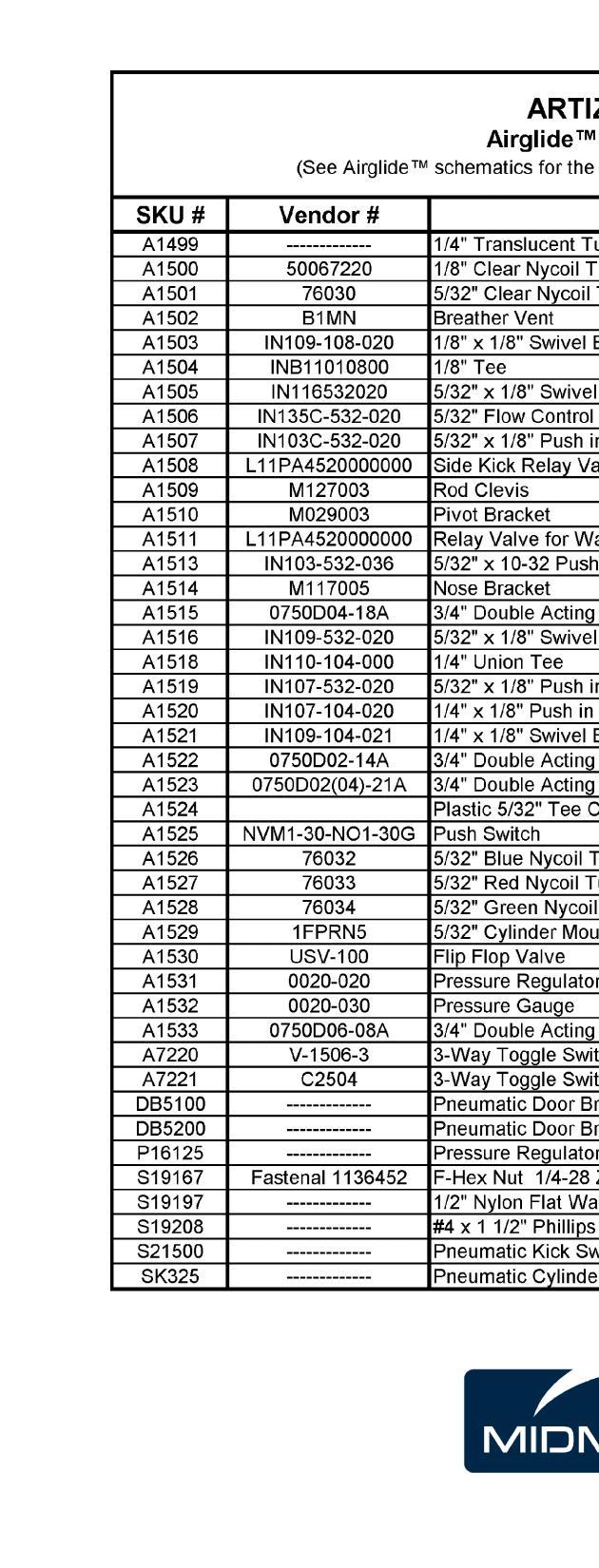
11 ARTIZAN
12
13 SETTING & USING THE TIMER CLOCK A B C BACK SIDE OF CLOCK TIMER 1 TIMER 2 CLOCK T1 T2 12:38 56 O N D E F H M S L START MEMORY CLEAR STOP BATTERY COVER G H I J M A. Timer 1 channel button B. Timer 2 channel button C. Clock button D. T1, T2 indicator for timer channel E. LCD display (hours, minutes, sec.) F. PM indicator for clock G. Hour time set button H. Minute time set button I. Second time set button J. Clear button K. Start/Memory/Stop button L. Magnet M. Battery cover N. Clip O. Hanging hole K Installing Clock / Timer A. Remove clock / timer from box located in cabinet and push clock / timer into opening. Installation of Power Supply for Clock / Timer (if required) B. Plug power supply to electrical outlet. C. Install grommet into upper cabinet. D. Route power supply wire through cabinet. E. If necessary, install grommet into task light cover. F. Plug power supply cord into the back of the clock / timer. page 14

14 Solid Surface Care & Maintenance CARE AND MAINTENANCE Caring for your Wilsonart Gibraltar Solid Surface countertop or surface is as simple as wiping the surface with a damp cloth. If a stain develops, wipe it away with soap and water. Or if you prefer wipe it clean with Windex. If a stain doesn t respond to soap and water, for a matte finish, apply an abrasive cleanser and buff with a Scotch-Brite pad using a circular motion. The same technique can be used for cigarette burns. If you have a gloss finish, please contact your dealer or fabricator before attempting repairs. For minor cuts and scratches, simply sand lightly with a medium (220 grit) sandpaper, then follow with a fine (320 grit) sandpaper. Finally, touch up the finish by buffing with a Scotch-Brite pad. PRECAUTIONS Do not expose the surface to harsh chemicals, such as paint remover, turpentine, nail polish remover or stove and drain cleaners. If these chemicals come in contact with the surface, immediately wash them off with water, using appropriate safety measures to avoid injury. Always use a cutting board instead of cutting directly on the surface. While minor cuts and scratches can be repaired, care should be taken to prevent them in order to keep the surface looking as good as new. page 15
 Pull out on the drawer slightly. D) Lower the drawer back down while pulling out on the drawer. Drawer Installation A) Fully extend drawer glides from the cabinet.")
 Extend the glide to its outermost position. Push the release levers in and remove the drawer member of the sides.")
 Remove the cover caps on the drawer side by hand. 2) Height Adjustment: Rotate in either direction to adjust the drawer front vertically.")
 4) Side Adjustment: Adjusts the drawer front horizontally. Turn in either direction.")
15 D 3 GA1106 GA1105 Drawer Removal, Installation and Adjustment Drawer Removal A) Open drawer completely. B) Lift up on the drawer front until the front of the box releases from the glide. C) Pull out on the drawer slightly. D) Lower the drawer back down while pulling out on the drawer. Drawer Installation A) Fully extend drawer glides from the cabinet. (Optional) B) Place the drawer on the glides. C) Push the drawer in completely. D) Cycle drawer a couple times to ensure that the drawer is securely attached to the glides. A B C Full Extension Glide Removal & Installation... 2 Removal A) Extend the glide to its outermost position. Push the release levers in and remove the drawer member of the sides. 4 5 Drawer Member PULL PUSH Cabinet Member Installation A) Line up the drawer member to the cabinet member and push the drawer into its compartment. GA1107 Drawer Front Adjustment and Removal 1) Remove the cover caps on the drawer side by hand. 2) Height Adjustment: Rotate in either direction to adjust the drawer front vertically. 3) Tilt Adjustment: Adjust after the drawer front is installed to ensure the drawer sides meet square with the drawer front. (Only available on large drawer boxes.) 4) Side Adjustment: Adjusts the drawer front horizontally. Turn in either direction. 5) Tension/Removal: For large drawers, turn the screw toward the front of the drawer until the front detaches from the box. Repeat this procedure on both sides of the drawer. For small and medium drawer boxes, turn the screw toward the back of the drawer to remove the front.


 Screw C adjusts the door in the C direction. Make adjustments to top and bottom hinge as necessary.")


16 D Door Removal, Installation, and Adjustment Hinge 1 & 2 Adjustments Use a phillips head screw driver for the following steps... A) Screw A adjusts the door in direction A seen in the Adjustment Direction Guide B) Screw B adjusts the door in direction B. Equal adjustment must be made to all hinges on the door for it to move the desired distance. C) Screw C adjusts the door in the C direction. Make adjustments to top and bottom hinge as necessary. Note: Use a level to ensure the door is level and plumb. Preferred gaps are approximately 1/8 between doors and 1/16 between accents and doors. Hinge 1, 2, & 3 Installation F) Hook the hinge to the mounting block at point F G) Latch at point G by pressing the hinge against the hinge block. 180 Hinge Adjustments D) Loosen screw D and adjust door gap and angle using a level. Tighten screw D when positioned correctly, 180 Hinge Hinge 1 & 2 Removal E) Press button at point E at the back of the hinge and pull away from cabinet. G F B Hinge 1 Hinge 1 & 2 Adjustment Direction Guide E A C A E Hinge 2 C B A C Hinge 3 C A B GA1044 E B Soft Close Switch Door Removal
 Fully extend the arm from the cabinet.")
 Open door completely.")
 Tilt the top of the door away from the cabinet and lift up to free the door from the arms.")
 Slide the stabilizer rod cover caps onto the rod.")
17 GA1110 Important For correct operation of the lifting mechanism, the stabilizer rod must be installed. GA1108 Aventos HL Door Installation A) Fully extend the arm from the cabinet. B) Hook the bottom of the mounting block located on the door to the bottom of the arm and then tip the top of the door towards the cabinet to latch the door to the arms. Aventos HL Door Removal A) Open door completely. B) Support the door with one hand and push down on the door front release tab at the end of the arm assemblies. Do this for both arms. C) Tilt the top of the door away from the cabinet and lift up to free the door from the arms. Aventos HL Door Installation, Adjustment, and Removal Important Refer to the provided image for neutral tension adjustment. Aventos HL Stabilizer Rod Installation and Removal A) Slide the stabilizer rod cover caps onto the rod. B) Insert the stabilizer rod adapters being careful to line up the tabs. C) Attach the rod assembly to each arm assembly and tighten the locking screw. D) Slide the stabilizer rod cover caps over the locking screws. Note: To remove the stabilizer rod undo these steps in reverse order. GA1109 GA1109
 Remove servo if applicable.")
 To adjust the lift mechanisms tension use a #2 phillips head driver.")
 Re-install the cover caps.")
18 GA1113 GA1120 Aventos HL Door Installation, Adjustment, and Removal Aventos HL Tension Adjustment 1) Remove the cover caps by pulling out on them. 2) Remove servo if applicable. See Servo Drive Installation and Removal in this manual. 3) To adjust the lift mechanisms tension use a #2 phillips head driver. Close the door halfway as shown below and adjust until the door balances in that position. 4) Re-install the cover caps. WARNING Risk of injury from spring loaded arm Do not push the arm assembly down or leave in the down position without the door attached. GA1111 GA1112 Aventos HL Front Adjustment
 Hook the bottom of the mounting block located on the door to the bottom of the arm and then tip the top of the door towards the cabinet to latch the door to the arms.")
 Support the door with one hand and push down on the tab with a flat blade screw driver to release the clip mechanism on the arm assemblies. Do this for both arms.")

 Slide the stabilizer rod cover caps onto the rod. B) Insert the stabilizer rod adapters being careful to line up the tabs.")
19 GA1115 GA1119 GA1121 Aventos HS Door Installation A) Fully extend the arm from the cabinet. B) Hook the bottom of the mounting block located on the door to the bottom of the arm and then tip the top of the door towards the cabinet to latch the door to the arms. Aventos HS Door Removal A) Open door completely. B) Support the door with one hand and push down on the tab with a flat blade screw driver to release the clip mechanism on the arm assemblies. Do this for both arms. C) Tilt the top of the door away from the cabinet and lift up to free the door from the arms. Aventos HS Door Installation, Adjustment, and Removal Important Refer to the provided image for neutral tension adjustment. The amount of tension can be seen on the scale below the adjustment screw. The tension should be the same in both left and right lifting mechanisms. GA1114 Aventos HS Stabilizer Rod Installation and Removal A) Slide the stabilizer rod cover caps onto the rod. B) Insert the stabilizer rod adapters being careful to line up the tabs. C) Attach the rod assembly to each arm assembly and tighten the locking screw. D) Slide the stabilizer rod cover caps over the locking screws. GA1114 Note: To remove the stabilizer rod undo these steps in reverse order. WARNING Risk of injury from spring loaded arm Do not push the arm assembly down or leave in the down position without the door attached. Important For correct operation of the lifting mechanism, the stabilizer rod must be installed.
 Remove the cover caps by pulling out on")


20 1 1 GA1118 GA1122 Aventos HS Door Installation, Adjustment, and Removal Aventos HS Tension Adjustment 1) Remove the cover caps by pulling out on them. 2) Remove servo if applicable. See Servo Drive Installation and Removal In this manual. 2) To adjust the lift mechanisms tension use a #2 phillips head driver. Close the door halfway as shown below and adjust until the door balances in that position. 3) Re-install the cover caps. GA GA1117
 Set the drive unit to HL or HS depending on the unit purchased.")
 Insert the drive unit into the back of the lift mechanism and slide it forward.")

 Slide the latch on the servo back to the locked position. An audible click can be heard.")
 Pull the servo away from the lifting mechanism D and slide back to release the servo drive C.")
21 Servo Drive Installation A) Be sure the lift mechanism tension adjustments have been made and the door is properly balanced. B) Set the drive unit to HL or HS depending on the unit purchased. Making this selection will line up the servo actuator with the lift mechanism. C) Insert the drive unit into the back of the lift mechanism and slide it forward. D) Press the servo against the Lifting mechanism. Indicator pin from the servo should slide into the lifting mechanism and the orange slide will no longer be visible through the viewing window. E) Slide the latch on the servo back to the locked position. An audible click can be heard. Servo Drive Removal 1) Unlatch E by pressing down and sliding down. 2) Pull the servo away from the lifting mechanism D and slide back to release the servo drive C. C GA1126 GA1123 Servo Drive Installation and Removal B D GA1124 C GA1128 Important Servo must be installed when the door is in the fully open position E D GA1127
 Use the clamp connector to attach the cable to the power supply.")
 Tighten the screw to make the electrical connection between servo and power supply. Use a #2 phillips head screw driver.")
 Lift orange cable lock lever.")
22 C GA1125 Servo Drive Power Supply Installation 1) Route the power cable from the upper, down through the column and into the lower center module C. 2) Use the clamp connector to attach the cable to the power supply. Be sure that all barbs are straight before tightening the connecting block. 3) Tighten the screw to make the electrical connection between servo and power supply. Use a #2 phillips head screw driver. 4) Put on cover caps to insulate any exposed ends. GA1130 Servo Drive Electrical Installation Servo Drive Power Cable Installation A) Lift orange cable lock lever. B) Insert cable so that the shape of the cable matches the cable receiver. C) Once cable is inserted press down on the cable lock lever. A B GA1131 GA1132
 Start reference run Deactivation 5) Reset motion 6) Reset")

23 -Deactivation confirmation -Deactivation confirmation Servo Drive Activation and Setup 1) Activating the Servo Drive switch Motion LED Signals Optional features 3) Activating synchronization 4) Activating collision avoidance Flashes orange -Reference run is required Lights orange constantly -Power available -Operating mode display 2) Start reference run Deactivation 5) Reset motion 6) Reset wireless Function Buttons Layout A) Drive unit B) <Reset Motion> button C) Motion LED D) <SWITCH> button E) <SYNC> button F) <COLL> button G) <Reset Wireless> button H) Wireless LED K) Servo Drive switch GA1141 Flashes orange quickly Wireless LED Signals -Reference run successfully completed -Reset Motion Confirmation B C Flashes green -Activation mode D E F Lights up green continuously -Activation confirmation A G H Flashes green quickly K Lights up red continuously GA1134 GA1133 GA1141
 Press and hold the Servo Drive switch until the LED Lights up continuously.")
 Press and hold the <Reset Wireless> button using a pen for at least 3 seconds until the LED flashes quickly.")
 Reference run is required. The orange light should be flashing.")

24 Flashes quickly GA1139 GA1140 GA1142 Servo Drive Activation and Setup Activating the Servo Drive switch A) Press and hold the <SWITCH> button until the LED flashes. B) Press and hold the Servo Drive switch until the LED Lights up continuously. C) Repeat steps A and B for additional Servo Drive switches in the cabinet. Reset Wireless A) Press and hold the <Reset Wireless> button using a pen for at least 3 seconds until the LED flashes quickly. Operation Lights up continuously Flashes Important Resetting wireless will deactivate all functions previously programmed into the Servo Drive units. Flashes quickly GA1135 Start a Reference Run A) Reference run is required. The orange light should be flashing. B) Close the door front manually C) Press on the front to activate the servo switch. The reference run will begin and the door will open and close twice automatically. Reset Motion A) Press and hold the <Reset Motion> button using a pen for at least 3 seconds until the LED flashes quickly. WARNING Interrupting the reference run will cause damage to the unit. Under no circumstances should the user try to manually interrupt or stop this process. A B GA1136 C
25
 651-7407 (800) 257-7407 Fax (270)651-1732 www.")
26 Midmark Corporation Glasgow Office 115 G.L. Comer Rd. Glasgow, KY (270) (800) Fax (270) REVISED
INSTALLATION AND CUSTOMER CARE INFORMATION 60 SERIES & 70 SERIES TREATMENT STATIONS
 INSTLLTION ND CUSTOMER CRE INFORMTION 60 SERIES & 70 SERIES TRETMENT STTIONS Customer Service and Technical Support: 8:00 M to 5:00 PM central (M-Th) 8:00 M to 4:30 PM central (Fri) Phone: 800-257-7407
C15C C15C. Page 1 of 20
 2 x Lid Front Hinge 1135 8 x M8 Bolt 8 x M8 Washer (3mm Thick) 4 x M6 Large washers 4 x M6 Spring washers 4 x M6 x 40mm Bolts 6 x M6 20mm Bolts 6 x M6 Washers 20 x Screws 2 x Lid mount gas strut bracket
TONNEAU COVER INSTALLATION INSTRUCTION. Toyota Hilux 407L
 TONNEAU COVER INSTALLATION INSTRUCTION Toyota Hilux 407L Piece Tonneau Cover Place these instructions in vehicle s glove box after installation is complete Care Instructions: Clean Tonneau Cover with a
One- Touch Installation Instructions
 One- Touch Installation Instructions 1 1 Height Adjustable Pivot w/ screws 9 Upper Work Surface 2 Rail Mount Knobs 10 Back Cover 3 Transformer 11 Center Pivot w/ screws 4 Support Legs 12 Left Monitor Arm
READ AND FOLLOW ALL SAFETY INSTRUCTIONS SAVE THESE INSTRUCTIONS
 5 Swift Lock Ready Shape Tree (Patent Pending) Instructions IMPORTANT SAFETY INSTRUCTIONS When using electrical products, basic precautions should always be followed including the following: READ AND FOLLOW
D40C HINGE # x Support Plate x M8 Bolt 8 x M8 Washer 6 x M6 20mm Bolts 6 x M6 Washers 19 x Screws
 HINGE # 1017 2 x Support Plate 1018 8 x M8 Bolt 8 x M8 Washer 6 x M6 20mm Bolts 6 x M6 Washers 19 x Screws 2 x Lid mount gas strut bracket 1041 2 x Self tap strut mount 1040 1 x Central Lock bracket 1510
READ AND FOLLOW ALL SAFETY INSTRUCTIONS SAVE THESE INSTRUCTIONS
 7.5 Swift Lock Ready Shape Tree (Patent Pending) Instructions IMPORTANT SAFETY INSTRUCTIONS When using electrical products, basic precautions should always be followed including the following: READ AND
3PC TONNEAU COVER INSTALLATION INSTRUCTIONS. Ford Ranger/Mazda BT-50 (without bedliner)
") 3PC TONNEAU COVER INSTALLATION INSTRUCTIONS Ford Ranger/Mazda BT-50 (without bedliner) Care Instructions: Clean Tonneau Cover with a mild detergent and water solution. Do not use abrasive cleaners or solvents.
3PC TONNEAU COVER INSTALLATION INSTRUCTIONS Ford Ranger/Mazda BT-50 (without bedliner) Care Instructions: Clean Tonneau Cover with a mild detergent and water solution. Do not use abrasive cleaners or solvents.
Installation Instructions
 Installation Instructions SELECTRONIC PROXIMITY TOILET CONCEALED FLUSH VALVE. &. GPF Certified to comply with ASME A..M 00 AS America, Inc. Concealed Flushometer for -/" Top or Back Spud Bowls MODEL NUMBERS
INSTALLATION & OWNER S MANUAL
 Page 1 of 16 INSTALLATION & OWNER S MANUAL YAMAHA VIKING CAB KIT WITH HARD DOORS p/n: 1YAMVK fits model years 2014- (fits Yanmar Bull model years 2017-) NOTE: By design, the doors are made to not be removable!
Q15P. Mitsubishi MQ Triton Dual Cab
 Mitsubishi MQ Triton Dual Cab Page 1 of 12 Fitting Instructions Part Number Mitsubishi MQ Triton Dual Cab 2015+ To suit Sports Bars Check contents of kit before commencing fitment and report any discrepancies
Proper installation of this product requires the installer to have a good understanding of automotive electronics, systems and procedures.
 ENGINEERING COMPANY INC. 51 Winthrop Road Chester, Connecticut 06412-0684 Phone: (860) 526-9504 Fax: (860) 526-4078 Internet: www.whelen.com Sales e-mail: autosale@whelen.com Canadian Sales e-mail: autocan@whelen.com
DUETTE POWERRISE SHADES
 DUETTE POWERRISE SHADES A B OPEN CLOSE INSTALLATION OPERATION CARE PRODUCT VIEW Spacer Blocks Installation Brackets End Cap Sensor Eye and Manual Button Fabric-Covered Valance PowerRise with Platinum Technology
(W) INSTALLATION INSTRUCTIONS GRILLE GUARD TOYOTA TUNDRA / SEQUOIA PART # &
 INSTALLATION INSTRUCTIONS GRILLE GUARD TOYOTA TUNDRA / SEQUOIA PART # &") (W) INSTALLATION INSTRUCTIONS PART # 501894 & 501895 PARTS LIST: 1 Grille Guard 4 3/8" Flat Washers 1 Driver/Left Frame 2 3/8" Nylon Lock Nuts 1 Passenger/Right Frame 4 12mm Plastic Washers 1 Driver/Left
(W) INSTALLATION INSTRUCTIONS PART # 501894 & 501895 PARTS LIST: 1 Grille Guard 4 3/8" Flat Washers 1 Driver/Left Frame 2 3/8" Nylon Lock Nuts 1 Passenger/Right Frame 4 12mm Plastic Washers 1 Driver/Left
Installation Instructions
 COLONY/COLONY SOFT Bidet Faucet and Transfer Valve with Speed Connect Drain Congratulations on purchasing your American Standard faucet with the Speed Connect drain, a feature found only on American Standard
A-dec 371L or 571L Dental Light on an A-dec 361, 362, or 363 Support Center INSTALLATION GUIDE
 A-dec 37L or 57L Dental Light on an A-dec 36, 36, or 363 Support Center INSTALLATION GUIDE 37L 57L Before You Begin WARNING Failure to turn off or disconnect the power before you begin this procedure can
Auto-Lift Operating System
 Installation Instructions Parasol Cellular Shades Auto-Lift Operating System CONTENTS Getting Started: Product View... 1 Tools and Fasteners Needed... 2 Installation: Installation Overview... 3 STEP 1
TABLE OF CONTENTS. Ram Assembly
 TABLE OF CONTENTS DUC Cover------------------------------------------------------------------------------------ 00 Table of Contents----------------------------------------------------------------------------
SAM Series 2-Wire and 3-Wire Clock
 Installation Manual V9.0 SAM Series -Wire and 3-Wire Clock Current as of November 06 The Sapling Company, Inc. SAM Series -Wire and 3-Wire Clocks Table of Contents Table of Contents Important Safety Instructions
LARGE CAPACITY INCUBATOR Installation, Operation and Maintenance Instructions
 LARGE CAPACITY INCUBATOR Installation, Operation and Maintenance Instructions GENERAL 2 Inspection 2 Location 2 INSTALLATION 2 Door Alignment 2 Shelf Installation 2 Remote Contacts 2 2-10 Volt DC Output
FlexJet Carriage Circuit Board (PCB) Replacement
 Replacement") P/N: 111484 R0 14140 NE 200th St. Woodinville, WA. 98072 PH: (425) 398-8282 FX: (425) 398-8383 ioline.com FlexJet Carriage Circuit Board (PCB) Replacement Notices: Warning! Ensure that all AC power cables
P/N: 111484 R0 14140 NE 200th St. Woodinville, WA. 98072 PH: (425) 398-8282 FX: (425) 398-8383 ioline.com FlexJet Carriage Circuit Board (PCB) Replacement Notices: Warning! Ensure that all AC power cables
INSTALLATION MANUAL SPECTRUM BRAKE CONTROL
 INSTALLATION MANUAL 51170 SPECTRUM BRAKE CONTROL TABLE OF CONTENTS Controls & Components Tools List Before You Begin Wiring Wiring Diagram Mounting the LED Display Rotary Knob Wiring the Plug Connector
EZ LITE CRUISER. Service & Maintenance Manual
 EZ LITE CRUISER Service & Maintenance Manual Table Of Contents Introduction to the EZ Lite Cruiser 3 Identification of Components 4 Controller System Component Diagram 6 Controller System I/O Ports Detail
INSTALLATION INSTRUCTIONS
 INSTALLATION INSTRUCTIONS Accessory Application Publications No. S P/N 08V31-S0X-100 1999-2001 ODYSSEY AII 20677 Issue Date AUG 1999 PARTS LIST 2 Fog lights Switch Fuse label Right bracket Relay B, 4-pin
ATS-9600/9700 TABBER/LABELER
 ATS-9600/9700 TABBER/LABELER INSTALLATION AND OPERATING INSTRUCTIONS SAFETY PRECAUTIONS THIS EQUIPMENT PRESENTS NO PROBLEM WHEN USED PROPERLY. HOWEVER, CERTAIN SAFETY RULES SHOULD BE OBSERVED WHEN OPERATING
INSTALLATION INSTRUCTIONS
 INSTALLATION INSTRUCTIONS [1] Description: Tow Hitch Wire Harness Kit [2] Application: Nissan Rogue Note: Tow Harness application is limited to specific vehicle option packages that include tow harness
Installation Instructions
 86-95 Suzuki Samurai Hood Latch & Release Cable (SKU# SEB- HLCK) Installation Instructions Note: S u z u k i h a s upgraded both of these parts and they will not work with the hood latches and release
Depress each tab as you pull the bezel off. The bezels are tight. L.H. shown.
 2013-2014 Ford Mustang V6 & Boss 302 Lower Valance Fog Light Kit Parts List: Quantity: Tool List: Fog light & bulb with bracket 2 Flat head & Phillips screwdriver Black bezels 2 Ratchet & Socket set OR
Loose Components. VetPro 5000 Wall / Cabinet Mount Installation. Applies to Models:
 VetPro 5000 Wall / Cabinet Mount Installation warning Equipment not suitable for use in the presence of a flammable anesthetic mixture. Applies to Models: 8001-001 8001-002 8001-005 8001-006 Loose Components
TOYOTA TUNDRA TVIP V4 REMOTE ENGINE STARTER (RES)
") Preparation Part Number: 08586-OC910 Conflicts Do not install into vehicles without RKE systems. Recommended Sequence of Application Item # Accessory 1 TVIP/RES Any TVIP or RES system 2 XM Radio NOTE:
Preparation Part Number: 08586-OC910 Conflicts Do not install into vehicles without RKE systems. Recommended Sequence of Application Item # Accessory 1 TVIP/RES Any TVIP or RES system 2 XM Radio NOTE:
TOYOTA COROLLA ILLUMINATED DOOR SILLS Preparation
 Preparation Part Number: PT942-02140 Kit Contents Item # Quantity Reqd. Description 1 1 Illuminated Scuff plate, Front Right Hand 2 1 Illuminated Scuff plate, Front Left Hand 3 1 Door Scuff plate, Rear
Service Manual. Model Number: DF2426GB DF2426SS DF2550 DF2562. UL Part Number to 500
 Service Manual Model Number: DF2426GB DF2426SS DF2550 DF2562 UL Part Number 6905050100 to 500 IMPORTANT SAFETY INFORMATION: Always read this manual first before attempting to service this fireplace. For
INSTALLATION INSTRUCTIONS GRILLE GUARD TOYOTA TUNDRA TOYOTA SEQUOIA PART # P2067
 INSTALLATION INSTRUCTIONS GRILLE GUARD 07-14 TOYOTA TUNDRA 08-14 TOYOTA SEQUOIA PART # P2067 PARTS LIST: GRILLE GUARD 1 Grille Guard 2 10mm Cam Lever Quick Release Bolts with Special Pivot Washer 1 Driver/left
MAZDA BT-50 (October 2011 Production Onwards) 1 & 3 PIECE HARD TONNEAU REMOTE LOCKING KIT INSTALLATION INSTRUCTIONS
 1 & 3 PIECE HARD TONNEAU REMOTE LOCKING KIT INSTALLATION INSTRUCTIONS") MAZDA BT-50 (October 0 Production Onwards) & 3 PIECE HARD TONNEAU REMOTE LOCKING KIT INSTALLATION INSTRUCTIONS Installation Time: Approx. 0 Minutes Care Instructions: Clean Tonneau Cover with a mild detergent
MAZDA BT-50 (October 0 Production Onwards) & 3 PIECE HARD TONNEAU REMOTE LOCKING KIT INSTALLATION INSTRUCTIONS Installation Time: Approx. 0 Minutes Care Instructions: Clean Tonneau Cover with a mild detergent
PRODUCT MANUAL Gecko Wireless One Zone LED Dimmer and Receiver
 Product Description The Gecko Wireless One Zone Wall LED Dimmer has been designed to bring light control easily. No wires or switch box locations are needed, just stick or mount the Gecko to any flat location
H15P. Toyota Hilux A-DECK Dual Cab
 Toyota Hilux A-DECK Dual Cab Page 1 of 14 Fitting Instructions Part Number H15 Toyota Hilux A-DECK Dual Cab 2015+ To suit Sports Bars Check contents of kit before commencing fitment and report any discrepancies
Installation and Operation
 HQ Installation and Operation Copyright 2013 Handi Quilter, Inc. All rights reserved. Printed in the U.S.A. 08/2013 Table of Contents Contents of the HQ HighRise kit 3 Installation 6 Operation of the HQ
TOYOTA COROLLA ILLUMINATED DOOR SILLS Preparation
 Preparation Part Number: PT942-02140 Kit Contents Item # Quantity Reqd. Description 1 1 Illuminated Scuff plate, Front Right Hand 2 1 Illuminated Scuff plate, Front Left Hand 3 1 Door Scuff plate, Rear
Tru-Billet Climate Control Knob Installation Instructions
 P/N S197-525-07 2007-08 Tru-Billet Climate Control Knob Installation Instructions Thank you for your purchase of SilverHorse Racing products. Please read all directions before beginning the installation.
3PC TONNEAU COVER WITH SPORTS BAR INSTALLATION INSTRUCTIONS
 3PC TONNEAU COVER WITH SPORTS BAR INSTALLATION INSTRUCTIONS TC00d / Vehicle Description: NISSAN NAVARA D0 DUAL CAB 3-PIECE TONNEAU COVER PARTS LIST NO. PART NAME QTY. NO. PART NAME QTY. NO. PART NAME QTY.
Service Manual Air Plus Second Stage
 Service Manual Air Plus Second Stage Includes XS Series Second Stage Copyright 2002, Cressi-sub Revised 3/2002 2 Air Plus Second Stage Service Manual Contents BEFORE STARTING... 3 DISASSEMBLY... 3 PARTS
INSTALLATION GUIDES OUTDOOR LIVING
 S OUTDOOR LIVING TABLE OF CONTENTS 12 Volt 12 Watt DC Transformer Page 2 12 Volt 50 Watt DC Smart Transformer Page 3 12 Volt 50 Watt Smart Transformer Control Page 4-5 Waterproof Dimmer For 12W Transformer
2005 and 09 Mustang install instructions Sequential / Chase Unit Partial Plug-N-Play Kit Meter4it Eng. Updated: 3/28/09
 Updated: 3/28/09 Verify content of kit: 1- Unit with wiring harness 1- Red power wire with 15 amp fuse 1- Color instruction 2- Velcro for mounting 1-Driver taillight harness 1- Passenger taillight harness
INSTALLATION INSTRUCTIONS FORD F-150 2WD & 4WD RETAINS FACTORY TOW HOOKS PART #P3063
 INSTALLATION INSTRUCTIONS FORD F-150 2WD & 4WD RETAINS FACTORY TOW HOOKS PART #P3063 PARTS LIST: 1 Grille Guard 2 10-1.5mm Nylon Lock Nuts 1 Driver/Left Frame Mounting Bracket 4 12mm Plastic Washers 1
PRELIMINARY INSTALLATION INSTRUCTIONS PARTS LIST. Combination light switch Right fog light. 4 Self-tapping washer-screws.
 INSTALLATION INSTRUCTIONS Accessory S P/N 08V31-SCV-100D Application 2009 ELEMENT (SC) Publications No. AII 40515 Issue Date OCT 2008 PARTS LIST Combination light switch Right fog light Left fog light
INSTALLATION INSTRUCTIONS
 INSTALLATION INSTRUCTIONS WARNING: NEVER EXCEED YOUR VEHICLE MANUFACTURER'S RECOMMENDED TOWING CAPACITY Q24 5TH WHEEL HITCH TABLE OF CONTENTS Page# Description 1 Warnings & Precautions 2 Assembly & Installation
TOYOTA TUNDRA COLD AIR INTAKE Preparation SEQUOIA
 Preparation SEQUOIA 2008 - Part Number: PTR03-34070 (5.7L) PTR03-34072 (4.7L) Kit Contents: 5.7L Item # Quantity Reqd. Description 1 1 Lid: Air Filter 2 1 Inlet Pipe: 5.7L 3 1 Air Filter: TRD Conical 4
ATS-9600/9700 TABBER/LABELER
 ATS-9600/9700 TABBER/LABELER OPERATOR'S MANUAL SAFETY PRECAUTIONS THIS EQUIPMENT PRESENTS NO PROBLEM WHEN USED PROPERLY. OBSERVE SAFETY RULES WHEN OPERATING THE TABBER/LABELER. READ THIS MANUAL CAREFULLY
Auto Sentry-eXP Maintenance. Revised 12/21/07
 Auto Sentry-eXP Maintenance Revised 12/21/07 Maintenance Procedures for Auto Sentry exp Bill Dispenser Credit Card Reader Bill Acceptor Bill Dispenser Maintenance Bill Dispenser Problem / Cause Bill Dispenser
INSTALLATION INSTRUCTIONS GRILLE GUARD TOYOTA TUNDRA TOYOTA SEQUOIA PART # 2067/2067-2
 INSTALLATION INSTRUCTIONS 07-15 TOYOTA TUNDRA 08-15 TOYOTA SEQUOIA PART # 2067/2067-2 PARTS LIST: 1 Grille Guard 2 10mm Cam Lever Quick Release Bolts with Special Pivot Washer 1 Driver/left Frame Mounting
Large Case Storage - Replacing Case Lock System
 Large Case Storage - Replacing Case Lock System 1 Table of Contents If you have a problem, question, or request, call your local dealer, or Steelcase Line 1 at 888.STEELCASE (888.783.3522) for immediate
GENUINE FOG LIGHT INSTALLATION AND USER S INSTRUCTIONS
 GENUINE FOG LIGHT INSTALLATION AND USER S INSTRUCTIONS Thank you for purchasing a genuine Mazda accessory. Before removal and installation, be sure to thoroughly read these instructions. Please read the
INSTALLATION & OWNER S MANUAL
 INDUSTRIES, LLC. INSTALLATION & OWNER S MANUAL CAB INSTALLATION INSTRUCTIONS KUBOTA GRAND L 40 SERIES HARD SIDED CAB ENCLOSURE (p/n 1KGL4AS) This Curtis Cab is designed and manufactured for use only as
1PC TONNEAU COVER INSTALLATION INSTRUCTIONS. Ford Ranger (with bedliner)
") PC TONNEAU COVER INSTALLATION INSTRUCTIONS Ford Ranger (with bedliner) Care Instructions: Clean Tonneau Cover with a mild detergent and water solution. Do not use abrasive cleaners or solvents. Place these
PC TONNEAU COVER INSTALLATION INSTRUCTIONS Ford Ranger (with bedliner) Care Instructions: Clean Tonneau Cover with a mild detergent and water solution. Do not use abrasive cleaners or solvents. Place these
with Touch & Go Feature
 Cellular Shades Veronica Valencia Blackout Cellular Shades POWER TOUCHTM RECHARGEABLE with Touch & Go Feature Installation & Care Instructions 152730 4/19/2017 GETTING STARTED A few simple tools are required:
* APPLICATION MODELS VARY. WE RECOMMEND TO VERIFY FITMENT BEFORE BEGINNING INSTALLATION PROCESS.
 Parts included (1) Main Grille Polished - Part #6214760 OR Black - Part #6214761 Hardware included (8) - #8 x 3/4 Black Screws (8) - #8 Flat Nuts (3) Push Nut Retainer Clips START HERE PLEASE READ AND
ft. ft Signature Balsam Fir Tree ITEM Item 68607
 7.5 7.5 ft. ft Signature Balsam Fir Tree ITEM Item 68607 PARTS LIST A. BOTTOM B. MIDDLE C. TOP D. TREE STAND NUMBER OF PERSONS RECOMMENDED FOR ASSEMBLY: 2 SKU 68607 7.5 Signature Balsam Fir 2114 TIPS STANDARD
TOYOTA TUNDRA TVIP V4 Preparation
 Preparation Part Number: PT398-00100 PT398-00100-AA Conflicts Do not install into vehicles without RKE system. Recommended Sequence of Application Item # Accessory 1 TVIP/RES Any TVIP or RES system 2 XM
Service Manual Air Tech Second Stage
 Service Manual Air Tech Second Stage Copyright 2002, Cressi-sub Revised 3/2002 2 Air Tech Second Stage Service Manual Contents BEFORE STARTING... 3 DISASSEMBLY... 3 PARTS CLEANING AND LUBRICATION... 9
INSTALLATION INSTRUCTIONS FORD F-150 2WD & 4WD RETAINS FACTORY TOW HOOKS PART #P3063
 INSTALLATION INSTRUCTIONS FORD F-150 2WD & 4WD RETAINS FACTORY TOW HOOKS PART #P3063 PARTS LIST: 1 Grille Guard 2 10-1.5mm Nylon Lock Nuts 1 Driver/Left Frame Mounting Bracket 4 12mm Plastic Washers 1
NOTE: DISCONNECT MAIN POWER LOCK OUT AND TAG BEFORE PERFORMING ANY PROCEDURES IN THIS SECTION.
 M E C H A N I C A L S E T U P & A D J U S T M E N T S NOTE: DISCONNECT MAIN POWER LOCK OUT AND TAG BEFORE PERFORMING ANY PROCEDURES IN THIS SECTION. NOTE: All adjustments should be made with the sealer
INSTALLATION INSTRUCTIONS FOR DSP9600/9100 WHEEL BALANCER
 Form 5063T, 06-05 Supersedes Form 5063T, 02-04 INSTALLATION INSTRUCTIONS FOR DSP9600/9100 WHEEL BALANCER This document provides the information needed to install the DSP9600/9100 Wheel Balancer. NOTE:
Installation Instructions
 Installation Instructions SELECTRONIC PROXIMITY DUAL FLUSH TOILET FLUSH VALVE. /. GPF,.8/. GPF Certified to comply with ASME A.9.M 00 AS America, Inc. M90 REV.. Exposed Flushometer for -/" Top Spud Bowls
16" STAND FAN WITH REMOTE
 OWNER S MANUAL 16" STAND FAN WITH REMOTE MODEL:FS40-8JR READ AND SAVE THESE INSTRUCTIONS Attention: Pictures in the IM are for reference only. CAUTION Read rules for safe operation and instrucions carefully.
GENUINE PARTS INSTALLATION INSTRUCTIONS
 GENUINE PARTS INSTALLATION INSTRUCTIONS 1. 2. 3. 4. DESCRIPTION: APPLICATION: PART NUMBER: KIT CONTENTS: Accent light Kit Versa Note 999F3 4Z000 - Accent Lighting Kit. 999Q9 AY000 - Accessory Service Connector
9-I DUETTE SHADES POWERVIEW MOTORISATION
 SECTION: 9-I DUETTE SHADES POWERVIEW MOTORISATION 9-I DUETTE SHADES POWERVIEW MOTORISATION Product View Installation Brackets End Cap Manual Control Button Fabric-Covered Headrail Bottom Rail Battery Wand
Maintenance Adjustments
 4 Maintenance and Adjustments Chapter Contents Cleaning the Printer and Paper Handling Accessories..... 158 Cleaning the HP Digital Copier....................... 161 Cleaning ADF and Glass............................
ATTACH YOUR RECEIPT HERE ITEM # FT. PRE-LIT DOUGLAS FIR TREE. MODEL #DF-75C85 Español p. 8
 ITEM #0776 7. FT. PRE-LIT DOUGLAS FIR TREE MODEL #DF-7C8 Español p. 8 ATTACH YOUR RECEIPT HERE Serial Number Purchase Date Questions, problems, missing parts? Before returning to your retailer, call our
In area - A -, a proper seal must be made against the top of the window glass.
 Door window, adjusting Page 1 of 3 Audi > B3 > 1994-1998 Body Exterior, Interior 61 - Convertible top, checking and adjusting Door window, adjusting Sections C-C and D-D. Adjust door window so that window
VHM-P (Non-Locking) and VHM-PL (Locking) Variable Height Arm with Slide-In Mounting Plate
 and VHM-PL (Locking) Variable Height Arm with Slide-In Mounting Plate") 3875 Cypress Drive Petaluma, CA 94954 800.228.2555 +1.707.773.1100 Fax 707.773.1180 www.gcx.com VHM-P (Non-Locking) and VHM-PL (Locking) Variable Height Arm with Slide-In Mounting Plate (Refer to qualified
3875 Cypress Drive Petaluma, CA 94954 800.228.2555 +1.707.773.1100 Fax 707.773.1180 www.gcx.com VHM-P (Non-Locking) and VHM-PL (Locking) Variable Height Arm with Slide-In Mounting Plate (Refer to qualified
INSTALLATION & OWNER S MANUAL
 p. 1 of 15 INSTALLATION & OWNER S MANUAL Polaris Ranger 500-800 PathPro SS Cab (fits 2010 - current) (p/n: 1POLRFS1) The contents of this envelope are the property of the owner. Be sure to leave with the
Installation Instructions Pro Stick Shifter
 Installation Instructions Pro Stick Shifter Part Number 80701, 80702 & 80706 2012, 2010, 2008, 2001, 1998 by B&M Racing and Performance Products The B&M Pro Stick shifter #80701 and #80706 comes equipped
Installation Instructions
 Installation Instructions SELECTRONIC DC POWERED PROXIMITY EXPOSED URINAL FLUSH VALVE 0., 0., 0. &.0 GPF Certified to comply with ASME A.9. 0 AS America, Inc. Exposed Flushometer for /" Top Spud Urinals
Validator and Control Board Update Instructions for BC1
 Validator and Control Board Update Instructions for BC1 Installation Overview The update kit for the Rowe BC1 enables the changer to interface with a Mars AE/VN 120-volt validator. The validator determines
Model 2300JL Installation Guide
 Model 2300JL Installation Guide POWER ACCESS CORPORATION 4 HERSHEY DRIVE, DOCK 4 ANSONIA, CT 06401 800-344-0088 WEBSITE: www.power-access.com EMAIL: salesinfo@power-access.com 1 STANDARD PARTS MODEL 2300JL
M GT 2005 up Mustang ENGINE START Push-Button INSTRUCTION SHEET
 Please contact the Ford Racing Techline for the most current instruction information @ (800) FORD-788!!! PLEASE READ THE FOLLOWING INSTRUCTIONS CAREFULLY PRIOR TO INSTALLATION!!! OVERVIEW: The following
Model 2300DL Installation Guide
 Model 2300DL Installation Guide POWER ACCESS CORPORATION 4 HERSHEY DRIVE, DOCK 4 ANSONIA, CT 06401 800-344-0088 WEBSITE: www.power-access.com EMAIL: salesinfo@power-access.com 1 STANDARD PARTS MODEL 2300DL
VHM-P (Non-Locking) Variable Height Arm with VESA Mounting Plate for 75 x 75mm or 100 x 100mm applications
 Variable Height Arm with VESA Mounting Plate for 75 x 75mm or 100 x 100mm applications") 3875 Cypress Drive Petaluma, CA 94954 800.228.2555 +1.707.773.1100 Fax 707.773.1180 www.gcx.com VHM-P (Non-Locking) Variable Height Arm with VESA Mounting Plate for 75 x 75mm or 100 x 100mm applications
3875 Cypress Drive Petaluma, CA 94954 800.228.2555 +1.707.773.1100 Fax 707.773.1180 www.gcx.com VHM-P (Non-Locking) Variable Height Arm with VESA Mounting Plate for 75 x 75mm or 100 x 100mm applications
3875 Cypress Drive Petaluma, CA Fax
 3875 Cypress Drive Petaluma, CA 94954 800.228.2555 +1.707.773.1100 Fax 707.773.1180 www.gcx.com VHM-P (Non-Locking) Variable Height Arm with Fixed Angle Front End for Flat Panel / Keyboard Bracket (L Brackets
INSTALLATION INSTRUCTIONS
 INSTALLATION INSTRUCTIONS MODEL: GRAFTON RH-510 1 REV.A Restoration Hardware Balance Pressure Tub /Shower Set Specification Diagram Ensure that the stop ring () is correctly installed, prior to finished
INSTALLATION INSTRUCTIONS TRAILER HITCH MAIN HARNESS KIT
 PART NUMBER: 0000-89-N30 GENUINE ACCESSORIES INSTALLATION INSTRUCTIONS TRAILER HITCH MAIN HARNESS KIT APPLICABLE MODELS: 2016 > CX-9 PACKAGE CONTENTS: INSTALLATION INSTRUCTIONS QTY 1 CABLE TIE MOUNT QTY
INSTALLATION & OWNER S MANUAL
 Rev. C, p. 1 of 18 INSTALLATION & OWNER S MANUAL KUBOTA RTV 400 CAB (Not for use on RTV 500) These instructions are for installation of the complete cab as well as the modular components. DESCRIPTION:
INSTALLATION & OWNER S MANUAL
 INSTALLATION & OWNER S MANUAL CAB INSTALLATION INSTRUCTIONS JOHN DEERE 3000 SERIES (4200/4300/4400) (4210/4310/4410) & (3120/3320/3520/3720) HARD SIDED CAB ENCLOSURE (p/n 1JD3520AS) SOFT SIDED CAB ENCLOSURE
LOOKOUT LED LIGHT BAR INSTALLATION MANUAL 7900 SERIES
 LOOKOUT LED LIGHT BAR INSTALLATION MANUAL 7900 SERIES Your purchase of a Wolo warning light is the perfect choice to compliment your vehicle. Wolo s warning lights are manufactured with the finest materials.
Battery Powered Sensor Operated Lavatory Faucets. Plug-in Transformer Powered Sensor Operated Lavatory Faucets PARTS LIST
 1A 1B 8 EAF-100/150 I.I. Rev. 0a (11/02) Code No. 0816542 INSTALLATION INSTRUCTIONS ELECTRONIC, SENSOR OPERATED LAVATORY FAUCETS EAF-150 Series Battery Powered Sensor Operated Lavatory Faucets 2 3 7 10
DMR 3005 WM ONE ZONE WIRELESS DIMMER RECEIVER
 E363518 DMR 3005 WM ONE ZONE WIRELESS DIMMER RECEIVER 20725 NE. 16 AVE. #A-33 MIAMI, FLORIDA 33179 Tel: (305) 652-2599 Fax: (305) 650-8812 www.lumiron.com Email: sales@lumiron.com 1 Benefits and Features
Washroom Dispenser Service and Parts Manual Tork Elevation M2 Pro Centerfeed Towel Dispenser A; A Revision Date:
 Dispenser Parts Tork Centerfeed Pro Hand Towel Dispenser: M2 Pro Centerfeed System: 559020A White; 559028A Black Dispenser Dimensions HxWxD Inches (cm): 14.4 x 9.4 x 9.0 (36.6 x 22.9 x 22.7 cm) Centerfeed
TV Lift System Model L-75i Installation Instructions
 TV Lift System Model L-75i Installation Instructions Below is a parts list describing all of the items included with the Model L-75i Lift System. Contact: Support@Nexus21.com Toll Free: (866) 500-5438
Installation Instructions
 Installation Instructions SELECTRONIC EXPOSED TOILET FLUSH VALVE AC POWERED PROXIMITY.,.8,.6,.6/. &.8/. GPF Certified to comply with ASME A.9. 08 AS America, Inc. MODEL NUMBERS 606B. 606B. 606B.6 606B.7
INSTALLATION INSTRUCTIONS BULL BAR DODGE RAM 1500 PART # B-D1091;B-D2091
 INSTALLATION INSTRUCTIONS PART # B-D1091;B-D2091 PARTS LIST: Qty Description Qty Description 1 Bull Bar 10 12mm Lock Washers 2 Upper Frame Brackets (for trucks without tow hooks only) 8 12-1.75mm Hex Nuts
TOYOTA COROLLA 2010 TVIP V4 PREPARATION
 PREPARATION Part #: PT398-02080 or PT398-02100 NOTE: Part number of this accessory may not be the same as the part number shown. Conflicts: Do not install into Manual Transmission Vehicles or Vehicles
Installation Instructions
 Installation Instructions SELECTRONIC EXPOSED TOILET FLUSH VALVE AC POWERED PROXIMITY.,.8,.6,.6/. &.8/. GPF Certified to comply with ASME A.9. 0 AS America, Inc. MODEL NUMBERS 6067. 6067. 6067.6 6067.7
FOR SIT-STAND WORKSTATION
 INSTALLATION MANUAL FOR SIT-STAND WORKSTATION Weight Capacity: 6.5-24.5 lbs. 6017180 Rev. B Contents Tools Required / Supplied Part Kits / Warnings/Disclaimers...2 Base Installation Clamp Mount Base Location...3
Installation Guide. Philips MP20/30/40/50 IntelliVue VHM Wall Mount Kit
 Installation Guide Philips MP20/30/40/50 IntelliVue VHM Wall Mount Kit The purpose of this guide is to: 1. Describe attachment of Table Top Mount to Mounting Adapter. 2. Describe attachment of Mounting
VOLKSWAGEN AMAROK MY17> 1 & 3 PIECE HARD TONNEAU REMOTE LOCKING KIT INSTALLATION INSTRUCTIONS
 VOLKSWAGEN AMAROK MY7> & PIECE HARD TONNEAU REMOTE LOCKING KIT INSTALLATION INSTRUCTIONS Care Instructions: Clean Tonneau Cover with a mild detergent and water solution. Do not use abrasive cleaners or
Table of Contents. Timer Identification Timer ID BLU-U Features: 1K 6K BLU-U Features 1K 6K
 DUSA Pharmaceuticals, Inc. Table of Contents Go to Chart # Timer Identification Timer ID BLU-U Features: 1K 6K BLU-U Features 1K 6K BLU-U Features: 10K BLU-U Features 10K BLU-U Symptom Fans Running, Timer
SCION xb HEADREST DVD RSE Section I Installation Preparation. Part Number: PT
 Section I Installation Preparation Part Number: PT900-52080 Kit Contents Item # Quantity Reqd. Description 1 2 DVD Headrest Unit 2 2 Headrest Extension Cables 3 1 Audio Interface Module 4 1 Audio Interface
Installation Instructions Pro Bandit Shifter Fits: GM Powerglide Automatic Transmissions
 Installation Instructions Pro Bandit Shifter Fits: 1962-1973 GM Powerglide Automatic Transmissions Part # 80793 WORK SAFELY! For maximum safety, perform this installation on a clean, level surface and
INFINITY-3 STROBE LED BAR INSTALLATION MANUAL 7700 SERIES
 INFINITY-3 STROBE LED BAR INSTALLATION MANUAL 7700 SERIES Your purchase of a Wolo warning light is the perfect choice to compliment your vehicle. Wolo s warning lights are manufactured with the finest
INFINITY-1 HALOGEN LIGHT BAR INSTALLATION MANUAL 7000 SERIES
 INFINITY-1 HALOGEN LIGHT BAR INSTALLATION MANUAL 7000 SERIES Your purchase of a Wolo warning light is the perfect choice to compliment your vehicle. Wolo s warning lights are manufactured with the finest